#archived-shaders
1 messages · Page 30 of 1
Thanks a lot! I will try it. Would you recommend any way to compare and benchmark the performance of both?
oh god benchmarking shaders 😅 i don't really know how to do it tbh
Use the frame debugger in Unity?
Yeah, I can try to do it with 1000 samples and compare than 🙂
anyone able to help?
I upgraded a nonURP project to URP and now all my default materials are pink.
I know this is a common problem but the common sollution isn't fixing it.
I already did Edit > Render Pipeline > URP > upgrade all, and this did not fix the pink
How do I fix the default material to not be pink?

Is there an easy way to prevent moiré patterns from appearing in procedural textures?
Real textures use mip maps and antialiasing but neither of those can be done to procedural
hard nasty lines

as a result of this

The DDXY Node is your friend in this scenario. It's the same function shaders use to calculate which mip level should be used. Without going into the math behind it (because I don't understand it) you give it some value that differs between pixels, like UV, and it will return a value that becomes larger when there's a bigger difference between neighboring pixels.
You can then use this value to blend in something that will minimize the aliasing, like to lerp to a solid color.
https://forum.unity.com/threads/low-resolution-or-bad-anti-aliasing-on-normal-from-height.1051733/
I have found this person's sollution explaining DDXY whenver I google this problem but I've never been able to successfully impliment it

Unity Forum
I was playing around with blending two textures together to creating some tiles with "grout" or something between them. I figured I could make a tile...
Im attempting to create a simple billboard shader, on a regular plane mesh. For some reason no matter what shadergraph I attempt, the planes wont look towards the camera

I found a shader on unity forums that does that but its written cg HLSL and not a shadergraph. Do you want me to try to re-find it?
https://forum.unity.com/threads/problem-solving-2d-billboard-sprites-clipping-into-3d-environment.680374/ it is in here somewhere
Unity Forum
Hey guys, I've been experimenting with building a tactics engine using 3D geometry but 2D character sprites, similar to the Final Fantasy Tactics and...
Ive attempted to use this shader before and ran into some issues, but let me re attempt it and see what problems I ran into, as this is what i need 🙂
Worked out for me, thank you!

if I set the type to normal map, what will Unity do?
does it change encoding? the pixel data ?
I use texture.GetRawTextureData(), can get different result
It will import the texture with sRGB disabled, and store it in a dedicated normal map format, that is usually a two channels (R&G or G & A) texture.
how can I get the non-dedicated normal map format,
I want to get the value as the default texture
but without change it to the normal type
you need to bake/convert the texture into normal map outside of unity, then import it as default texture.
I want to sample the unity-normal map in shader, then readback out to a defaut texture
how to do it ?
Keep the import settings to default texture type, but still uncheck sRGB.
You might also want to increase the compression quality to avoid artifacts.
I want the scene material keep it's normal map
keep the normal map type, but get the default value...
I honestly don't understand what you are trying to do.
What do you mean by "default value" ?
default texture type
the rgb value
I'm trying to do something like compress the texture
I need to know the default value
because unity compress the normal map, and I don't know how they compress it
You'll need to either decode the sampled default normal map into normal value inside your shader, or decode the normal normal map into default value inside your code
@keen patio
You just have to sample the texture then, and you'll get the RGB value.
Unity doesn't do anything particular to the data, it just uses a dedicated format for normal map.
Like I said, normal map texture formats store the normal data in RG or GA channels.
It is then "unpacked" to convert to a vector3.
The unpack operation is relatively simple
normal.xy = sample.rg;
normal.x *= sample.a; // multiply r & a to accomodate to the different formats
normal.xy = normal.xy * 2.0 - 1.0; //remap from [0;1] to [-1;1]
normal.z = sqrt( 1.0 - dot(normal.xy, normal.xy)); // calculate the z value from xy, knowing that the normal vector length is 1

// you can now de-unpack if you want the texture original rgb color value :
color.rgb = normal.xyz * 0.5 + 0.5;

why, if I set it to default texture, then unchek sRGB, it get the same SAMPLE result?
how it recognizes it is or not a normal map?
In shader code, there is no way to recognize if it is a normal map or not.
but if I use default texture + non-sRGB, it still uses unpack normal
why they get the same result?
Because the shader does an unpack operation on this texture sample.
It is just doing it for this texture property, regardless of what texture is plugged.
Look at the "normal mapping" example here : https://docs.unity3d.com/Manual/SL-SurfaceShaderExamples.html
o.Normal = UnpackNormal (tex2D (_BumpMap, IN.uv_BumpMap));
Regardless of the format of the texture assigned to _BumpMap, it will be sampled and unpacked.
UnityWebRequestTexture.GetTexture how to load linear texture?
A bit out of topic for this channel. I suspect that it would only load sRGB textures

Hi! In un unlit shader, how can I save the effects of a fragment shader so that at the start of the next fragment shader it doesn't get reset? Let's say that in the first fragment I color a pixel green, in the second fragment I would like to see the same pixel colored green.
Thank you
This doesn't really make sense as fragment shaders run in parallel
No, I explained myself badly. I would like to change the color of the material where I click the mouse. But If I click more than once, I would like the previous points not to be canceled by the new colored point.
Is this in 2D? Or 3D, mesh or quad? What render pipeline?
Is a material of a 3d mesh gameObject. But I can use also a render texture if needed. Pipeline URP
Then you probably want to look into
first part of https://www.youtube.com/watch?v=c7HBxBfCsas (Bleeding-Edge Effects)
or https://www.youtube.com/watch?v=YUWfHX_ZNCw (Splatoon - Painting Effect)
Both of those involve additively rendering the mesh in uv space to a render texture
Thank you I'll give a look
Why does it takes 4-5 times longer to read from a large rendertexture than it does to read from a large texture2d of the same size and file size and format in a compute shader?
Hi, I'm getting some weird artifacts when using power on a gradient noise, even with low values like 2 any idea?

The gradient noise node occasionally returns negative values which the power node doesn't support. You can use a Saturate node in-between to make sure values stay between 0 and 1.
Ho these are negative values 🤦♂️ that makes so much sense now, thanks for the tip
I am trying to achieve a sorta strata-fied look for a shader. Similar to 3D printed objects, or Topographical maps.
My question is - I want to keep the "edges" to be the same size no matter where they appear on the mesh, but I am not sure how to prevent the texture from stretching wildly across the gentle slope 🤔


Im currently using world position as UV coordinates similar to tri-planar shader, but I am not sure how to fix the problem of the texture stretching on gentle slopes
you need to use the surface normal to determine which world coordinates to use for the UVs
on a surface that is flat like the top there you should be using x and z as the uv coords for example
which is kinda where the "triplanar" in triplanar comes from, if I'm not mistaken
Right sorry I misesxplained what I meant.
I am not looking to stretch a texture over it's top surface, I am looking to draw lines based on its Y height in the scene
There is no texture I can project onto it's top that will represent this data that im aware to make
I will try to find a better visual example where words fail
better example - the way there are clear steps formed from the gentle slope, but without stretching a texture

I am trying to achieve a similar appearance - clearly separated steps of height on a slope, but without the line of each clear step stretching down the length of the slope the way it is in my above 3d render shader example
even better example

so if there was a tall shear cliff you'd expect it to be perfectly flat?
I am not sure what you mean by this. A tall sheer cliff would look like this

That is easy to achieve though
the problem is not tall sheer cliffs, but wide gentle slopes

here is a good example that maybe is clearer
no matter what angle the slope is, the line delineating the edge of that height does not stretch
uniform line width
I am sorry if I am not clearly explaining what I mean

I want these two widths to not be different
Does any of this make sense?
Googling a contour map is maybe what I am trying to get? But examples I am seeing are not able to solve the same problem im having: stretched contour lines

aaaaa the net says screenspace partial derivatives will solve this but that sounds like something infinitely beyond anything I can do
I believe so yeah - exactly, a contour line
It seems... difficult to do without a geometry shader though
Yeah I might be just SOL here and will have to explore other options
i will keep trying for now
searching contour is showing people doing it
so it can be done
I just need someone to tell me how they did it in stupid english for my dumb ape brain
I feel like there should be an answer somewhere in the world position and the normal of the surface
where somehow it's angle where like, flat is 1, and vertical is 0, gets added to the line to make it thinner
that sounds easy but how do I do it
I want... the object's... surface normal... but only from top down??
what projection is that?
ill take a break for now and try more later
normal vector in world space Dot (0, 1, 0) gives 1 straight up and 0 perpendicular, it sorta works


I think the only problem right now is finding the right value that makes it look the most consistent
What I have in mind is using a modulus of worldPos.y to make height based gradient, then using an edge detection which detect if the gradient changed direction, maybe using post process if a consistent line width is required
btw, you can also just use worldNormal.y instead
yup looks like that works to get the same result

I was hoping to avoid post process with this if possible because it was going to be used a lot and many lines.
Yeah, using post process could add another complication in the future I guess...
I was using sine instead of mod because mod was giving me super weird results I didnt know how to use

another problem with mine is that at distances, it looks pretty awful

lots of moiré
Articles on computer graphics, math and art
this stuff seems to have answers on how to fix it but im not alegebra enough to figure out how to use it

this might have the sollution for the anti aliasing
How would I draw mesh instances in the scene editor?
Can you pass a struct with a Vector3 var1; to an HLSL struct with a float3 var1; ??
or do I have to do float x, float y, float z on both sides
I just assume vector3 to float3 doesn't work in a compute shader
because Vector3 is a Unity type
Vector3 will translate correctly, because it's blittable and it's in the same order as float3, xyz.
I'm assuming you're talking about in a ComputeBuffer, because you can't set struct properties directly.
hello i am making a simple shader that takes a texture with two colors (R & G), split them up and then replaces them with other colors and then combines them with each other. the thing is i can't figure out a way to allow for the replaced color to have a alpha. is that possible in some way?

After getting the replaced color out of the Replace Color node, use the Combine node to combine it with the original alpha.
i meant that each color that i choose to replace with can have their own alpha
i found the color mask node just now trying to figure something out whith that
That's how I understood you and my answer reflects that.
When I say "the original alpha", I mean the alpha of ColorR/ColorG.
The alpha of those colors are ignored now because the Replace Color node only reads the RGB channels and returns RGB.
when i do that the whole texture gets the alpha of the multiple of both colors, instead of being separated by color.

i figured out a way around this by using color mask

Hey all, possibly an odd question, but here goes.. I have a render texture that is applied to the default "Unlit" shader material. Is there a simple way to modify that texture/shader/material combo so that the texture is mirrored vertically?
Why is Unity so stupid that it doesn't generate all the boilerplates shaders for URP?
But you have to add all the damn boilerplate manually.
I don't want to use Shader Graph 💢 😠
(╯°□°)╯︵ ┻━┻
It is in the works : https://forum.unity.com/threads/block-shaders-surface-shaders-for-srps-and-more-public-demo-now-available.1350497/
Unity Forum
Greetings from the Shader team!
We heard your feedback regarding the need for SRP compatible surface shaders, as well as a better way to integrate...
Did you try using the texture tiling offset values ?
Setting tiling.y to -1 should be enough to mirror it vertically.
Maybe need to also play with the Y offset if the texture isn't set to repeat
From the look of it, it seems to be an over engineered way to do a lerp of two colors based on the green channel of the texture.
what could be the cause of these 1 px lines all over my mesh?


I've tried adjusting all the values but I cant seem to eliminate the pixel noise
it onyl shows up if the texture is not one complete solid color

so I assume the problem is related to the texture itself in some way
it shows up even if I set compression off
It's called by jumps in the UV + how mipmaps are sampled. See https://www.cyanilux.com/faq/#sg-pixellated-seams
Ah that worked like a charm after setting the wrap mode to mirror. Thanks, that was simple!
Ahh I see 🤔 I will read this,
XY problem ultimately, im really trying to wrap a texture around a contour
A better way to fix this is by using a Custom Function node with Out = SAMPLE_TEXTURE2D_GRAD(Texture, Texture.samplerstate, frac(UV), ddx(UV), ddy(UV)) with inputs “Texture” (Texture2D), “UV” (Vector2) and outputs “Out” (Vector4). No need to use the Fraction node here as it is handled in the code - but only on the coordinates used for sampling and not on the derivates!
``` Trying your solution now 👍Why don't you directly use the texture built-in tiling ?
(in your case, directly connect the output of the multiply node to the uv of the sample)
I don't know what you mean by that
The texture import setting "repeat"
It is set to repeat
Then, try what I said 🙂
Then it should already repeat without needing the Fraction nodes

The fraction node would be more useful if you needed to say, repeat a section of a larger atlas. Then you'd want to use the SAMPLE_TEXTURE2D_GRAD.
I think the reason why I was using fraction is because I need to make specific adjustments to it in the 0 to 1 range that I don't know if I can make as easily in the 0 to infinity range
But I dont know for certain if that will actually be a problem until I get to that step, which I am going to start on next
@regal stag "only on the coordinates used for sampling and not on the derivates!" In the fix for the fraction version, what does this mean?

if I end up needing it want to know what that means
Then you can either go for the custom node route and use fraction for the UV, or you can use the infinite range UVs, compute the adjustements in the 0to1 range, and "inject" them back in the uvs
It's just saying the Fraction node is moved into the code, but only on the parameter used for sampling, not ddx/ddy ones (frac(UV), ddx(UV), ddy(UV))
(I know I'm not clear in text, not easy to explain without showing in a graph)
Im getting purple checkerbox, I think I messed up the formatting somehow

syntax error }

Needs a ; at the end
Ah yes, I copied it directly from here, you might want to add the ; at the end there for other people who are like me and don't know better

Yup that fixed it though 👍 If I end up needing to use the fract instead of the multiply directly
Hello everyone. I am looking into making a specific shader but with little to no shader experience. The effect I am wanting to achieve is taking in a 2D texture, extruding it out to cause it to have width, then mirror the texture on the other side. Any information on this kind of effect would help me out. Can this be done and what method(s) does it use?
So, basically, transforming a 2D shape into a 3D extruded object ?
Correct 🙂
For example, I am taking in a Minecraft sword as a place for me to start. I want to control how much of width the sword will have and have it extrude out.
Look into parallax (+occlusion) mapping for the "extrusion" part, and for the mirror : well, that's just the matter of disabling the culling on the shader 🙂
Okay sweet, that defiantly gets me started. Thank you very much
Anyone with experience have an idea of what could be causing this? It's acting a little weird and I believe it has something to do with ZWrite
https://gyazo.com/dceb2217ca5a27d75535997f34531b68

hi neeed shader help
Mate, post your issue.
Nobody can help you if you have not even asked a question
sir i have shader the problem is titling is not working

Do you guys know how i can change the edges of a shader to move around smoothly kinda like this? 2D shaders. I haven't been able to find a tutorial online.


Anyone know how to add lightprobe information to a shadergraph 👀
I cannot figure this thing out
hi
sounds like some voronoi noise mixed inside of a circle maybe?
I'm really new to shaders. How could i change the edge of the circle using a voronoi noise? should i use a position node or is there a node to change the edge of the shader
please any one help me
Well I got it. Turns out shaders suck and it's better to just re-generate the mesh with the edges.

remade it. not sure if i can figure out how to make it better than this

oh i switched up where the Red and green should go
I'm looking for some ideas on how to fix this: I've created a volumetric shader and a camera that renders it to a custom render texture at 1/8th resolution, I can then upscale this on a canvas:

I can also render the rest of the scene to a render texture as well:

However I'm not sure how to overlay the two, I need to access the scene's depth buffer, but from the camera that is rendering the tornado
For some reason when trying to overlay the RawImages, it does this:


When I type in the full name of my subgraphs, the create node dialog doesnt show them, does anyone know why this is the case?

they show up when I type dice, but if I type the full diceshader, they wont show
Im trying to google the problem but I cant find the keywords to solve it
'shadergraph subgraph filter search not showing'
'shadergraph subgraph not showing when using create node filter'
i just keep finding results about outputs or inputs not showing up or connecting
but my problem is that the subgraph itself wont show up when I write its exact explicit name
Oh thats annoying, typing Dice (space) Shader works
even though there is no space.
Any recommendations for this community? It’s been a blocker for our team since we upgraded versions of unity
No way to know, but since it is a Standard Shader, maybe check to see if there's lighting setting differences in your newer unity installation. Or throw some lights around that "grey" area and see if it lights up. Shadow mapping, or GI might be different between the two installations/versions.
Otherwise, since you're using BIRP, why not use either a custom vert/frag or a Surface Shader if you need lighting.
I've no other idea why a white object would end up grey.
Is there an easy way to render only a camera's depth texture to a render texture?
I just need a way of passing the depth texture from one camera to a shader on a different camera
is there a way to add lighting to a vert/frag shader?
i have a basic sunlight set up, that is one vector that the shader uses to determine how models are lit, which works fine for now, but in the case that i want actual pointlights (without casting shadows, i dont really need it) or i need a light beaming down from the hole in the roof or something, i cant really use this singular sunlight model
ive considered making a pointlight script that will take every material in the scene using the shader and pass some information about how far away it is and the light color and light intensity and whatnot for use in the shaders calculation (it would be added to the sunlight) but i stress that it would not only be unoptimized but also messy
like how would i have 2 pointlights in the scene without a table to hold each light and all of its data
or how would i occlude objects that are far away without having to check the distance of that object every single frame
for a single light, these calculations are fine, for 15 lights coming from lamps around a room, these calculations could be devastating
the issue isnt so much with the shader as it is with the passing of information about lights from the game to the shader
because if i wanted unlit lighting, i could probably just pass a color value and multiply it with the new color value for each light in the scene, and calculate light info in-scene
but the thing is, you cant really multiply lights
because if you have 2 lights on opposite sides of the object, and you try to bundle their position into one variable, you would get a point inbetween the two points with blended together colors, which would make the object be directly inside of the object
Maybe you can use unity_LightPosition, unity_LightColor & unity_LightAtten?
They are array of light up to 8 light source but they are calculated per vertex, not per fragment.
interesting, ill look into it, thanks
so let me get this straight, is LightAtten the factor of the light attenuation by the time it reaches the vert in world space or is it something different?
according to this
https://docs.unity3d.com/Manual/SL-UnityShaderVariables.html
Light attenuation factors. x is cos(spotAngle/2) or –1 for non-Spot Lights; y is 1/cos(spotAngle/4) or 1 for non-Spot Lights; z is quadratic attenuation; w is squared light range.
LightAtten z seems to be the light strength when it reach the vertex.

I've never tried them my self :p it's just that I remembered reading them when I was looking for how to use lightmap in vert/frag shader
alright, thanks
is it possible to make a shader that gets its points from two separate meshes and combines them
basically i have two cubes that touch each other and the default material makes it clear that there are two cubes but i want it to look like it's one long rectangular prism even though there are two separate cubes there behind the scenes
why does it not look like a rectangle, if you put two cubes right next to each other it looks like a rectangle
but let's say i have a material that isn't uniform across the surface of each cube, then you can see the division
like an outline for example
also if it's transparent you can see the inside edges of each cube
and i would like it to be transparent
ok good point
I would not know, I only know that you cannot add or remove vertecies inside the vertex shader. What you could do maybe is do it inside c# get the two mesh datas and then combine them
ah smart smart ig i could have the meshes of each cube stored but not displayed and then have a parent mesh that gets updated when the cubes change
thanks i will try that
Hello, I'm having a little bit of trouble with my toon shader, when I use it I'm getting weird light banding like this, the yellow and red bands are unintentional

Here is part of my shadergraph for it at the moment

I'll admit I'm not much of a shadergraph person and this is one I've been using for months now and I'm sure it's not made very well
I think the bands are a recent thing and I'm not entirely sure why
I played around with it so it's not how it is normally but the problem is still there regardless
Things like the CalcAdditionalSpecular not being connected isn't normal lol
I'd assume the bands are caused by the light color being put through a Step (with the Colorspace Conversions in bottom left)
It still does it even without that, I tried that from someone else having a banding issue and it helping them, but it didn't help it here
It still does it with this even

Hmm there's also a step node at the end, perhaps that is causing it too?
I'll play around with it a little bit more, it wasn't the issue either though
But I'll see if I can get more information to go off of
Hello I have a question I would like to ask, Now this might be a stupid question but I couldn't find anything. I would like to render a specific Object to one of the cameras but not to the others, now usually I can just assign the layers but how can I achieve the same with indirect gpu instanced objects
I can't see what else it would be really. But using a Step after multiplying with colours will produce that kind of banding. If you want a toon-shaded result, I'd assume you may want to handle the step on float values before.
For example, compare the output of these :

Okay thank you I'll try that 
Honestly
It might be something with just the GetMainLight idk, cause it's doing it for both my specular and diffuse
Unless I really am doing something silly
what is that subgraf even?
It's quite empty
Calls to Graphics.DrawMeshInstancedIndirect have a layer, as well as a camera parameter which should help. https://docs.unity3d.com/ScriptReference/Graphics.DrawMeshInstancedIndirect.html
It'd be from the actual hlsl file if anything but I'm going to play around with the shadergraph for a bit first
dang I missed that part in the documentation, fuck
thank you <3
Something which might help debug it a bit is to assign default values to your properties (under Node Settings tab of Graph Inspector while property is selected). That way your previews might show the colour banding too, helping to find where it starts.
Yeah, I think I might be close to finding something
Okay I found the issue, it was the step as you were suggesting, but the way I fixed it was to convert it to HSV, step, and then convert back to RGB
random question but is there a limit to how many structured buffers i can have in a compute shader other than memory? just hunting an unknown bug 
Hey there im new looking to get into making 3d retro games ive hit my first road bump, when I try to texture a tree the area around edges are black and when i set alpha transparency the texture becomes a muddy mess.
@gloomy gust easiest way is to just make an extra sprite sheet for your sprites with just an outline and overlay it
i found a shader online which is supposed to do the trick, but how am i meant to apply it to my character?

From what I can find, OpenGL sets the minimum to 8, and NVIDIA seems to support 16 at most.
👍 lower than i expected but still not over any, thanks.... now to continue bug searching with a blindfold
how do i apply shaders to things/
yo can I ask you for your mainlight code? also does it have shadows cast on it?
are you sure it can have shadows cast on it?
and can you show me the appearance of your nodes?
I'd like to see what you connected the attenuation to
I'm not at my pc anymore so unfortunately I can't show that, but yes it can have shadows cast on it

why does my outline shader look like this?

why does the material do that
how can i fix it?
seems we stole the same code, noice
why does the material look like this, because it doesnt in the inpsector

okay for some reason it works in the build version

Is there any way to make a gameobject more transparent without changing its materials?
you can disable its mesh renderer in code
I don’t wanna make it completely transparent
Seems like lack of depth buffering/proper render ordering based on distance to camera (please use screenshots, not images taken with a potato
Thanks
I've managed to fix a lot of the issues I was having yesterday and can now composite a scene with a correctly rendered tornado:

However, for the camera rendering the tornado, I want to render at a lower resolution, and then upscale it back to the original resolution
I tried:
    private void OnRenderImage(RenderTexture source, RenderTexture destination)
    {
        RenderTexture r = RenderTexture.GetTemporary(source.width / 16, source.height / 16);
        Graphics.Blit(source, r);
        Graphics.Blit(r, destination);
        RenderTexture.ReleaseTemporary(r);
    }
But this just pixelated the entire screen
I also think it is applying the pixelation after the raymarching, instead of before it, which would improve performance
@cobalt totemCould you explain your code in more detail?
- You make a low res render texture
- Blit the tornado camera's RESULT AFTER RENDERING IT to the low res texture.
- Blit that low res texture to the final destination
- release it.
Well, the camera may have just rendered the full res image. All you're doing is copying that to low res and the low res to destination.
That doesn't make sense to me but I may be missing something. And IDK where the ray marching came in but probably in the shaders used to render the tornado during the camera.render() operation.
What I THINK you want to do is to assign a low res texture to the camera to begin with. But I'm unclear if you did that or not. That would certainly speed up any ray marching, but it can have problems matching back to higher res depth buffer...you have to make "smart" depth decisions for pixels that cover, say, 4 other high-res pixels.
Thank you for your reply! I've now tried a script based on this: https://gist.github.com/snlehton/b015bd123c2dd1889b9c96edab40b8b6
However, it just renders at full resolution, here is the code:
using System.Collections;
using System.Collections.Generic;
using UnityEngine;

[ExecuteInEditMode]
[RequireComponent(typeof(Camera))]
public class DownUpSample : MonoBehaviour
{
    [SerializeField] private float renderScale = 8.0f;
    [SerializeField] private Camera _camera;

    public FilterMode filterMode = FilterMode.Point;

    private RenderTexture rt;

    private void OnPreRender()
    {
        int width = Mathf.RoundToInt(Screen.width / renderScale);
        int height = Mathf.RoundToInt(Screen.height / renderScale);
        rt = RenderTexture.GetTemporary(width, height);
        _camera.targetTexture = rt;
    }

    private void OnPostRender()
    {
        _camera.targetTexture = null;
        RenderTexture.active = null;
    }

    private void OnRenderImage(RenderTexture source, RenderTexture destination)
    {
        source.filterMode = filterMode;
        Graphics.Blit(source, destination);
        RenderTexture.ReleaseTemporary(rt);
    }
}
From what I understand, before it renders, the render target is set to a low resolution render texture (rt), I'm not sure why the source is blit to the destination instead of the rt, then the camera's render texture is set to null so that it renders to screen
Double check the scale setting in Unity's inspector.
The source is the rt, because that's the camera's current output texture. So the camera rendered its scene using the low-res temporary rt.
Hmm, it's definitely set to 8

If I do a Debug.Log(source.width) it outputs the screen's resolution
Also, destination is null
Put the/a debug in the OnPreRender() event see if it is called.


OK, why is it showing twice? You don't have this on both cameras, do you?
The docs for OnPreRender say:
When Unity calls OnPreRender, the Camera's render target and depth textures are not yet set up. If you need to access these, you can execute code later in the render loop using a CommandBuffer.
So it might be that Unity f-s over the render texture you set up. I doubt it, but I'm at a loss to explain what you're seeing.
https://docs.unity3d.com/ScriptReference/MonoBehaviour.OnPreRender.html
I suppose you could try creating a rt once, at the start of your program and assign it to the camera, and just let it be there for that camera's rendering. Rather than doing it every frame.
BB in a bit.
Ah okay, that’s a good idea, thank you I will give that a go
IDK that it will work. I'm at a bit of a loss, admittedly.
You'll have to make sure the camera clears that render texture, but it's probably already set to do that.
That script from github must have worked for someone before.
So I'm lacking information somehow.
Oh! The camera wasn't tagged as MainCamera
Okay, I've got it rendering low res, but when I add an additional camera to render the rest of the scene, it goes to hi res again:


IDK, unless it is rendered twice, IDK how it would have gotten to the high res version. Unless the ray tracing is doing that at high res (e.g. using the low-res to merge into high-res so the result just looks high res). Check the frame debugger.
GTG for now, good luck tracking all this down. The frame debugger and any other C# debugger will help you track the order of events. 🙂
P.S. I like the effect so far. It's not done, but it's on the way!
so i was working on getting unity lighting to be compatable with my shader, and this is what i have currently,
float4 light = float4(1, 1, 1, 1);
                    for (int i = 0; i < 8; i++)
                    {
                        float lightVal = unity_LightColor[i] * unity_LightAtten[i];
                        if (lightVal != 0)
                        {
                            light *= lightVal;
                        }
                    }
what im trying to do for right now atleast is get the light to illuminate any area within its range, it doesnt have to have falloff but i will try to achieve it eventually, this is how it looks now, my question is, unity_LightAtten doesnt seem to be working properly, what i assume it does is returns the light attenuation list of the first 8 lights attenuation values, which seems to be partly true, because it will illuminate any object in its radius, but it will fully illuminate it and wont illuminate based off distance
https://gyazo.com/8f9be2c0f135b895b42e0add533e01f4

it also seems to have issues with the lights coloring, and only really takes into account the value of the color and not the hue of the color https://gyazo.com/30ead3e687bad7f8da737481c95d8f00

am i using these values wrong?
im using the vertex lightmode tag btw
well it appears discord doesnt like me posting the full code
how would i get a camo effect using the shader graph
how would i get rid of the green (going for a desert camo)

nvm just used the replace color node
Does anyone know why my shader isn't animating ?

cause somehow it's supposed to be animated but isn't
I mean dosen't look the same

at all
ok kinda work now

don't worry guys my skills are bad it's my first time using unity
Hi, this is a test of a shader for drawing on a material. I would like to save on the render texture the color of every point that users clicks, but I can't save the state of the render texture and every time I draw a new point, it overwrites the previous one. Any inputs? Thank you.


After adding shaders to my game, my game no longer starts.
It stays stuck on this:

I tried using Adaptive Performance, but that didn't change anything
if I have roughness map how do i apply it to smoothness in unity
Either use the alternate solution, or invert it, as mentioned
would be hard to tell anyways from two still images of the scene 😅
Not sure for all of your question, but you're not using the vector element as values. You're only using the red component/x-component in your equation.
The documentation explains the attenuation vector's elements:
Light attenuation factors. x is cos(spotAngle/2) or –1 for non-Spot Lights; y is 1/cos(spotAngle/4) or 1 for non-Spot Lights; z is quadratic attenuation; w is squared light range. https://docs.unity3d.com/Manual/SL-UnityShaderVariables.html
So since light drops off at the square of the distance, maybe you want to come up with a calc that uses the the pixel's squared distance and the .w component of attenuation.
Note that light types are also encoded in the .w component of the position...0 for directional, 1 for attenuated/positional.
The color you're saving should be a float3 (vectorName.rgb)....right now you're just hard-coding white. But light * lightVal works....each component will be multiplied by the float lightVal. So that will scale the color intensity if lightVal is in the 0 to 1 range.
So this means you're using vertexColor flag (as you said) and that you're in deferred rendering, yes?
In your shader you aren't setting the uv. You'd want o.uv = v.uv; in your vertex shader.
Also, you should avoid creating new RenderTextures every frame. It would be better to have two RenderTexture fields outside the function scope, initialise them in Start, then switch between them as you blit. And clean up those textures in OnDestroy/OnDisable by using .Release();
Thank you. Sure it was an error, but It doesn't work by just add o.uv = v.uv;
I managed to save the render texture using a shader that receives the uv coordinates and not the world space coordinates. I don't know why it works and what changes between the two versions.
Shader "Unlit/Draw"
{
  Properties
  {
    _MainTex("Texture", 2D) = "white" {}
  }
    SubShader
    {
        Tags
        {
            "RenderType" = "Opaque"
            "RenderPipeline" = "UniversalRenderPipeline"
        }
      Pass
      {
        CGPROGRAM
        #pragma vertex vert
        #pragma fragment frag
        #pragma multi_compile_fog

        #include "UnityCG.cginc"

        struct appdata
        {
          float4 vertex : POSITION;
          float2 uv : TEXCOORD0;
        };

        struct v2f
        {
          float2 uv : TEXCOORD0;
          UNITY_FOG_COORDS(1)
          float4 vertex : SV_POSITION;
        };

        sampler2D _MainTex;
        float4 _MainTex_ST;

        v2f vert(appdata v)
        {
          v2f o;
          o.vertex = UnityObjectToClipPos(v.vertex);
          o.uv = TRANSFORM_TEX(v.uv, _MainTex);
          UNITY_TRANSFER_FOG(o,o.vertex);
          return o;
        }

        float _Hits[2];

        float mask(float2 position, float2 center, float radius, float hardness) {
                float m = distance(center, position);
                return 1 - smoothstep(radius * hardness, radius, m);
        }
        fixed4 frag(v2f i) : SV_Target
        {
            fixed4 col = tex2D(_MainTex, i.uv);
            float2 work_pt = float2(_Hits[0], _Hits[1]);
            float force = mask(work_pt ,  i.uv, 0.01, 1);
            return lerp(col, float4(0,1,0,1), force);
        }


        ENDCG
      }
    }
}
oh i thought it said half in the unity docs, not half4, mb
also why should i be saving a float3? isnt it rgba? or am i missing something?
oh wait you probably meant the lightval
ok yeah i see why
bit of a dumb mistake
Hey, y'all! I'm new to the server, so let me know if I'm asking in the wrong place. I'm getting started with the shader graph, working with 2D sprites. In this image, I have added a Texture2D with Reference set to _MainTex, and a Sample Texture 2D node. For some reason, the preview on the Sample Texture 2D is always blank/white no matter what I try. What am I missing?

The _MainTex reference will make the shader automatically use the sprite assigned when in scene/game. But while in Shader Graph, you would need to change the "Default" for the previews to be useful.
That seems to be what I'm missing... So I always need to set the Default to some texture to see it in Shader Graph?
The default values are used by previews yeah (as well as what the properties default to when a material is created)
That makes sense, thanks!
ok so
ive had this issue before, and im not sure why my shader is erroring without any error messages
No, lightVal can be a single float (makes sense). You can have the color be rgb or rgba, float3 or 4, but the A won't matter to you from what I see. At least for the light attenuation calc.
lightval was intended to be a color i think
cuz i was multiplying the light color by its attenuation
still having this issue, still cant post full code for some reason

ok this is stressing me out, idek where to begin with this error, because my shader keeps randomly erroring (going pink) and then not returning an error that even indicates a line
even if i remove what i did, itl still be pink
Hi @regal stag, much respect for your work man!
Could you add me on discord so I can present you an offer, of course if you're interested, thank you!
Not interested
Nah, it's the color.
Maybe in your code, to make it clearer for you, you can change the variable name "light" to be "pixelColor" or perhaps just "color".
you set it to white to start with because you're not texturing it or grabbing some vertex color or something. But "light" is confusing. It's the starting color. Full intensity white, full opacity. That's why it's a float4(1,1,1,1)
"lightVal" is the intensity of the falloff of the light.
because i couldnt post the full code, i think you are missing some much needed context
i might have to chop this up a bit cuz discord doesnt like me sending the full code for some odd reason
first bit
Shader "Materials/Splatter"
{
    Properties
    {
        _Albedo("Albedo", 2D) = "white" {}
        _Noise("NoiseMap", 2D) = "white" {}
        _Color("Color",Color) = (1,1,1,1)
    }
        SubShader
        {
            Pass
            {
                Tags { "LightMode" = "Vertex" }
                CGPROGRAM
                #pragma exclude_renderers d3d11
                #pragma vertex vert
                #pragma fragment frag
                #include "UnityCG.cginc"
                struct appdata {
                    float4 vert : POSITION;
                    float2 uv : TEXCOORD0;
                    float3 norm : NORMAL;
                    //float3 vpos : TEXCOORD2;
                };
                struct v2f {
                    float4 vert : SV_POSITION;
                    float2 uv : TEXCOORD0;
                    float3 norm : NORMAL;
                    //float3 vpos : TEXCOORD2;

                };
                fixed4 _Color;
                sampler2D _Noise;
                sampler2D _Albedo;
second bit ```csharp
float random(v2f vert2f)
{
float rand = frac(sin(dot(vert2f.uv, float2(12.9898, 78.233))) * 43758.5453123);
float4 randMap = tex2D(_Noise,float2(vert2f.vert.x + rand5, vert2f.vert.y + rand5) / 50);
return randMap.r;
}
v2f vert(appdata IN)
{
v2f OUT;
OUT.vert = UnityObjectToClipPos(IN.vert);
OUT.uv = IN.uv;
OUT.norm = IN.norm;
//OUT.vpos = IN.vpos;
return OUT;
}
fixed4 frag(v2f IN) : SV_Target
{
fixed4 pixColor = tex2D(_Albedo, IN.uv);
//*float4 light = float4(1, 1, 1, 1);
//for (int i = 0; i < 8; i++)
//{
// float4 lightVal = unity_LightColor[i] * unity_LightAtten[i].w//( * 3 / distance(IN.vpos - unity_LightPosition));
// if (unity_LightAtten[i].w != 0)
// {
// light = lightVal;
// }
//}
return (pixColor * _Color);// light;
}
ENDCG
}
}
}
commented stuff was me trying to backtrack cuz my shader randomly errored and i cant get it to not error
and it isnt telling me anything
and its pink as if it were erroring
but originally i was setting up a white color
then multiplying it by all the colors of all of the first 8 lights colors
and then multiplying my already existing texture and color by that light color
because if i added them, would it not just get lighter and lighter until it was full white?
lightval was intended to be the color of one light
its an iterration of the first 8 lights cuz i think it said it gives the first 8 lights from the scene
I see.
It's still basically a color (well, accumulated light mix, but that's where color comes from...light).
Yes, it would. (additive color might blow out, but might not depending on what you do).
Yes, you'd need at least a float3 or maybe float4 if you want to track something in alpha.
OK, let's take a look. IDK why discord isn't allowing your code post. You should be able to upload it as a text file too.
i dont really need alpha, no, but it was a float4 so it was just to amke sure
half4, actually
not sure what the fourth value is
cuz tbh this shader stuff is pretty new to me
wait wait
i dont think it was that hold on
oh wait it was
ok well apparently it can only use the forwardbase pass
wait no
ok theres one for the vertex pass so im good
still not sure why my shader is erroring without telling me stuff tho.. sorta annoying..

lol
and now my unity questions post about it is under moderation..
OK, 10 things at once is too much. 😉
So let's pare it down.
Firstly, are you in forward or deferred rendering path?
tbh, hell if i know
where can i check, and whats the difference
You're in BIRP, right? (built in, "old" style unity. Not URP or HDRP)
i seriously dont know, this is my first time working with unity shaders at all cuz i wanted more stylistic control over my game
Graphics settings.
Hang on, I'll have to fire up Unity. Takes a bit, unfortunately.
and thats in project settings?
Yeah
in the graphics tab?
well
uhh
most of the stuff is set as "Built-in shader" if that helps
the scriptable rendering pipeline asset is set to none
alright
We need to figure out forward vs deferred lighting path yet.
yeah, so where do i check that
alright, take your time
We'll return you to regular programming shortly.
pun probably intended
hold on, im gunna take a walk
i havent gotten much fresh air today
OK, I have the answer for you.
In graphics settings, there's "tiers". most are probably default.
But you look in the tier's properties, there's a "rendering path" setting.
Also on the camera, there's a rendering path setting, but it might be set to use the default from the graphics settings.
forward
Vertex
just vertex
capital V
Yeah, that.
That's a rendering path. So IF (big IF) you want to use vertex lighting, you use that pass and need to set the rendering path in the graphics settings for each tier to "vertex lit".
I'll be back in 10 minutes.
and what exactly is vertex lighting?
ill look it up actually
so if im understanding correctly, vertex lit is the simplest lighting and is based off per-vertex calculations?
with no support for hardly anything
cuz if im correct, thats what i want
only thing i dont exactly want is the per-vertex lighting
back now.
Uh, you use vertex lit path or you don't.
I mean, that's the top of the decision tree
thing is, i want the setting with the least built in options possible, but i dont want vertex based lighting
Then you use forward or deferred. And we'll throw out that code you're using and start over, because that code is for vetex lit path.
how much of it?
because i noticed on the api that there are similar options for deferred
Just the lighting part
Similar yes, not same though
There's 4 main lights for forward, with additional additive passes. Deferred is different, many lights.
I mean, hell, you can code your own lighting and only have one light if you want. But that's limiting.
so i just need to rethink it and recalculate it differently?

thats what i was doing
up until now
i was using a sun light approach where one light was cast from one direction in an orthographic style
but i realized i cant exactly do light coming in from a window or light emitting from a specific point that mixed with the sun light well
That says it is for deferred. So you'd be using deferred in that case.
so i decided to do my own lighting
then i had issues passing game data to the shader, yada yada, and now im using partly unity lighting
should i do legacy deferred though?
Oh god.
I'd say no. But I get confused as anyone on all these modes.
ok, ill start with standard more modern defferred and see from there
alright i set it up for defferred
but one thing before i begin rewriting this code
is there any way to re-enable errors in console before? i was getting shader errors just fine until recently, im not even sure what i did
Deferred is the most "expensive" and is used for lots of lights.
Forward is the middle ground and you have additive lights after the 1st 4.
deferred seems like what i want, at some points ill be using more than 4, at others not so much
but this issue is what really is getting me
because the shader is completely pink, even with all my latest code commented out, leaving only the basic unlit code i had that was working fine before

Change your last line to return fixed4(1,1,1,1);
If there's no errors in the console you could try checking if there is any errors listed in the Inspector on the shader asset itself
i assume this is because im using the vertex lighting mode tag and i have it set for deferred, so i need to figure out how to change it to something suited for deferred

if it isnt that, then i have no clue, but ill try to change that first
so i should be using this? im not seeing a pass type so i can assume so
ok now im a little confused
What exactly are you trying to do? Add shading to an unlit shader? Is there a reason why you aren't using a surface shader?
We're going to change the code anyway....
im not exactly sure what the purpose of surface shaders is thoug
I was about to get into that Surface shader issue too.
To do lighting.
Automatically.
well why would i want that
if i chose shaders specifically TO have control over things like lighting, i think ill stay away from surface shaders
So you're a masochist. Got it. 😉
sorta
i just want to have a low level understanding of the lighting im using, to an extent atleast
But what you're asking isn't simple, but it's great for learning.
how "not simple" are we speaking?
because i only really want simple lights with very basic falloff, and to go from there
i dont need all this next gen junk, or even really shadows
dont need emission either.. i dont need alot of stuff
i dont need reflections, i dont need ray tracing of any degree
all i need is very basic, almost cartoonish looking lights
Why not start, then, with the forward rendering path?
But let's talk for a second about forward vs deferred.
forward, you calc the first 4 lights for each pixel. So it is in the pixel shader.
Then, for more lights after that, you and up coding an additional "forward add" pass that uses additive color to add lights on top of that, one for each light in range.
In deferred, it is calculated for all lights by calling all objects in the rage of a light and adding in the light...so it is driven by a light list. That means for pixels not in range of a light, that light calc isn't needed. So if it only has one light, only one light calc is done, rather than at least 4 of them with forward (you still romp through that array and do if's and stuff in forward).
that uses additive color to add lights on top of that
what exactly do you mean by this? if i have 4 lights, one yellow, one green, one blue, and one purple, close to eachother but still decently far apart, casting light onto a single object, with light falloff, would they not add on to eachother as they fall off into eachother?
well from that explanation, deferred seems like the option im looking for
Well, yeah I guess.
But I'm talking about passes and loops more than pixel-color-math.
again, im pretty new to shaders or lighting in general, so what is a pass?
Deferred can be faster and supports a lot of lights, but OTOH, with real simple lighting it might actually be slower. There's overhead because it does a g-buffer pass first, n'stuff.
i can assume a loop is just a set of iterations (for every loop up to 5, add 10 to a variable, that sorta thing)
OTOH?
Pass tag.
Unity calls that "section" of the shader at a specific time. A pass.
On the other hand
so in my current shader, it is calling the code in my one pass every frame?
Yeah, for each object in that frame in fact, that is lit by that material using that shader.
right
see the thing is
But in forward, it would call the forward-base pass once, and then forward-add pass for each additional light after the first 4.
in my game, i will have a variety of simple and complex lighting in one place at a time
for example
there might be a dark hallway at one part, only illuminated by a single flashlight spotlight
but in another place i might have a room with a row of windows each with light beaming through them
so i believe id want deferred
Do you want to support running your game on fancy calculators? (low end mobile?)
i want to have the most support possible, but definitely not mobile levels of low
like most PCs
i dont plan to have it release on consoles, because striking a deal with them doesnt seem exactly realistic
so i mainly want mid to high end
i dont plan to sell this game for much money, rather to use this as a jumping off point, because i havent made any game before
well
made is the wrong word
published is more correct
ive made plenty of games that i backed out on, but i dont think itl be the same for this one
I assume you read this?
https://docs.unity3d.com/Manual/RenderingPaths.html
yup
It's hard for me to understand your use-case, or make any "real" recommendation, given that example with multiple windows. There's ways to fake that, though, and if it isn't the norm you probably don't need deferred. Forward has less overhead, but like that chart shows, doesn't get a "free" depth buffer and you'll want that if you intend to do volumetric lighting like light shafts "streaming through widows" or whatever.
You can force it on though, in forward.
So you get it either way.
i may want lights coming from multiple enemies in a room though
like enemies that emit light passively, enemies that throw balls that emit light, ect ect
not in the emissive sense
Alright, so read that chart again, and if OK, go with deferred.
yeah im going with deferred
but my issue now is
actually
let me try the idea you mentioned of returning a basic white color before trying other solutions to fix my no-error problem
OK, so that's done/decided.
You can write shaders to support both, BTW.

OK, let's look at how a deferred shader is set up, and get it working in most-simple mode.
Then you can work on the lighting part.
And add in the random number routine, etc.
Start with the basics, right?
right
but wait
before this, i just want to say
wait
let me test something
cuz i know it was set to SOMETHING before i changed it to vertex, that was working fine
ok so my shader must be written for forward rendering
or uh
maybe not
cuz setting it to that is still pink
ok well anyway
how is a deferred shader set up
im assuming ill be rewriting my entire shader, yes?
Meh, sort of. I mean, some code will copy over.
which parts
But you're going to hate me for this...
I recommend you start here:
https://docs.unity3d.com/Manual/SL-VertexFragmentShaderExamples.html
This is for forward rendering path though. But you can switch over to deferred later on.
This will give you the basics of a custom shader.
The reason I'm saying this is you're asking questions like "what is a pass?" and stuff.
correct me if im wrong, but im pretty sure thats what i had just set up
well that was because i wasnt sure what a pass was, but i think i understand the basics of how a vert-frag shaders works
Yeah, but work through it as a tutorial. Because the last 1/3 of that page is about lighting and passes.
cuz in this code, i set it up that exact way
alright
so i scanned through it
and uhh
hold on let me look at the start a bit
Also, check this carefully:
https://docs.unity3d.com/Manual/RenderTech-DeferredShading.html
note that you'll need the hardware to support at least 4 and possibly 5 render targets at the same time. If it cannot, it will fall back to forward rendering path.
So you end up supporting forward too, one way or another.
This shit gets complicated fast, unfortunately.
wait i think i get what you were trying to say earlier about forward lighting
that if i wanted the first 4 lights to respond to things like normal maps and whatnot, and if i wanted the rest of the lights to not respond to normal maps, as a performance measure, i should choose forward?
like i can program a different pass for the rest of the lights past the fourth one that take less calculations?
alright, in that case i want the forward path
but the cost is that for every pixel you render, you "romp" through 4 lights in your array for EVERY PIXEL.
Just for self lighting.
And deferred gets a "free" depth buffer and g-buffer before lighting is called and sometimes that's really convenient.
so with forward, i would have to run through calculations for all lights no matter if the object would even be visually affected
It all depends on if you want "normal lights" or some creating/weird "custom lighting".
Even then, in Surface Shaders you can create custom lighting models.
Right, at least for the 4 in the array for "ForwardBase".
so wait
and for deferred it occludes lights if they are outside of the range?
right
and whats a render target?
A memory buffer (think writable texture) that the camera/GPU/Shader stuffs the results into.
i believe i am using 1, but just to make sure, does this mean for example 4 screens of arcade machines that cameras render results to that is displayed ingame at realtime?
just any texture that a seperate camera must render into? (like double the rendering?)
Alright, uh, the results of rendering have to go somewhere.
It's either the GPU's own back-buffer, or in reality another memory buffer we call a render-target.
Multiple Render Targets (MRT) is a spec for the GPU hardware as to how many targets it can write to at one time.
For example, your shader could output an RGBA color to one render target, and a depth value to another render target, and a mask value to still a third render target IF YOU WRITE IT THAT WAY.
But GPU's have limitations, and some may not support 5 render targets at once, and that's what that write-up in the docs was saying and why it would fall back to forward rendering in some cases.
hold on so whats a depth value and a mask value?
I just used that as examples. But those things exist on GPU's too.
I think you need a GPU overview, with full respect.
Do you know what the GPU depth buffer is and how it is used?
I suggest checking the pinned resources at the top of this page, including the tuts in "The book of shaders" and stuff.
alright
We probably should have made a thread for all this....
probably, but this is shader discussion
Sure enough 🙂
And it's fun. GPU's are cool. Takes some time, but you sound like the kind of person that will stick with it and dig in.
yeah, i know like nothing about hardware, so itl be neat to learn
Just remember that Surface Shaders are CODE GENERATORS. You can use them to examine lighting code even if you insist on writing it yourself. So it might be fun to dig into that to at some point.
hm
You're jumping into the deep end right off.
But the surface shader output can be a bit off-putting due to the 50 (ha) variants that get generated into a 2000 line output.
Or you can just use surface shaders and make your life easier, but you won't learn as much about the nitty gritty stuff like you want to, at first.
Hi everyone! I have a shader related problem; I can't get an 8K image to 'wrap' around a ico-sphere properly, how do I fix this?

This is how the mesh looks like ish

looks like a uv mapping problem rather than a shader problem
UV unwrap it properly
@meager pelican so i found out my issue.. #pragma exclude_renderers d3d11 was making my shader uncompatable somehow, ill have to look into what it does
also i read up a bit more on how a GPU works at a surface level atleast
so i found out why it randomly breaks without errors
it keeps ADDING THIS every time i save the script and open unity, im not sure why
try unwrapping with sphere projection
make sure to look at it from the side to align the poles of the planet on the top and bottom
best use the numpad buttons
hi everyone
need 1 help
i want to merge to 2 shader i am new in unity shader
help please
Hi all, I'm going through Sebastian Lague's procedural landmass generation series and have hit a bit of a stumbling block when it comes to his terrain shader.
I'm taking it step by step and try to 'rebuild' it in HDRP's shader graph (full disclosure, I'm pretty new to the shader graph system, but have a basic understanding of how it works).
The two images show the 'original' shader, and where I'm at with the graph (apologies for the mess. lol.)
I'm struggling to see how I can 'attach' the inverse Lerp node to the 'saturate' node to follow on what's happening in the original shader.
Would anyone have any pointers please? 🙂


You cannot merge two shaders, you can have two different materials on an object which uses different shaders
I am not sure what you want to do
Oh, I may have figured it out. Rookie mistake on my part, but 1 question, how can I 'split' a vector3's output to seperate x,y,z 'channels'
use the split node
It's basically a shader that changes texture based on the height of the mesh.
or seperatexyz not sure how it is called
Ah okay, got confused cause it has rbga outputs. lol.
xyz and rgb are essentially the same
Yeah, I forgot that part. lol.
Gah, Shader Graph is so annoying.
Was hoping I could figure this out all by myself, but it's driving me nuts.
Would anyone be willing to help me out a little please. I don't want to be 'spoonfed' the whole solution, but a little nudge in the right direction would be very much appreciated.
If someone is willing, could you take a look at the attached shader (Unity Standard) and give me some pointers?
The problems I'm having are with the declarations of things (const int's and arrays and the like) The rest I think I can figure out for myself. But those declarations are annoying the crap out of me atm. 😦
Just to be clear, looking for help in converting to HDRP shader graph.
Might be the other way around....it has decided your shader is incompatible, so it adds that line to exclude dx11.
You can try adding things like #pragma target 3.0 or maybe 3.5.
But you're beating a dead horse, since you'll probably rewrite it in a different rendering path anyway.
For things like arrays/loops, you'll need a Custom Function node. File mode, as this uses a hlsl include file which allows you to declare stuff outside the function body.
https://docs.unity3d.com/Packages/com.unity.shadergraph@14.0/manual/Custom-Function-Node.html
@regal stag Okay thanks. Will take a look and see if I can figure it out. lol.
I'll also mention that macros used by URP/HDRP will be different.
UNITY_DECLARE_TEX2DARRAY(name) -> TEXTURE2D_ARRAY(name) SAMPLER(sampler_name)
UNITY_SAMPLE_TEX2DARRAY(...) -> SAMPLE_TEXTURE2D_ARRAY(textureName, samplerName, coord2, index)
Most of the common & texture ones are listed under : https://github.com/Unity-Technologies/Graphics/tree/master/Packages/com.unity.render-pipelines.core/ShaderLibrary/API
Also, (and I'm no HDRP expert nor SG expert, so grain of salt here) Unity is known to zero out declarations that have initializers on them. So they are zero rather than what you've declared their initial values to be. That would depend, of course, on the shader compiler and the type of declaration. A const static int like you have might just be substituted in directly by the compiler. But who knows?
It's best to use a MACRO imo, and let the constant be substituted in in-line. And for anything else, initialize it on the material instances.
If it's static I think it shouldn't get zeroed out, but yeah defining your own macro for those static consts would work too.
It shouldn't, imo.
But I'm also unsure as to what their actual results are (the problem def).
Not gonna lie, this is so frustrating. lol.
Iirc his shader is mostly just a gradient in height; you can take the height, invlerp between the min and max heights, saturate, and then plug that into a sample gradient (i think sample gradient saturates by default but no harm being safe)
Yeah that's basically what he does, but it's the arrays he uses to hold the textures that's bugging me atm, and the mapping to the normals of the generated mesh I'm just trying a couple of different/simpler things to see if I can figure it all out.
so im using something that is making it incompatible?
I thought this would be simple but I can't seem to figure it out: how do you get the current "frame number"? What I'm trying to do is split some operations across multiple frames, so on frame 1 I will calculate one quarter of what I need, then on frame 2 the next quarter and so on, so that the calculation is spread over 4 frames. I've tried using the time node, but I would rather do it on a per-frame basis
worth case you could use a global shader variable that you set via C# that tells the shader what frame number you are on
Hey everyone, I have a problem that I need to fix (might be a very dumb problem, sorry for that since I'm a newbie). I created a blank shader graph, and I'm not getting the template that I'd expect.
This is what I'm getting.

And the unity tutorials show this.

you have to go into graph settings, (should be a small box on the right of the shader graph) and add active targets like so.

for alpha clipping and such, scroll down till you see a header named Universal and Visual Effects and it should have Alpha Clip and Alpha Clipping
checkmark those two.
I think I found out what the issue is
I'm using the standard render pipeline instead of the URP or HDRP
Oh I see
You should have an option to create BuiltIn/Lit or Unlit graph, instead of a blank one
I don't unfortunately

I've put on a Material on my mesh and there seems to be some sort of line from going around the entire mesh in one motion, is this a mesh problem or can I fix it in unity?

UV map hasn't been unwrapped to account for the funnel shape
If you want to fix it in Unity you'd do something like project the texture in object space
Sorry, where would I need to go to do this?
Would someone be able to quickly explain to me why this doesn't work? I assume I'm misunderstanding how the vector3 node works?

Can anyone please help my Toon Shader doesn't have shadows cast on it, even though I have done everything correctly

Redoing the UVs you would do in whatever modelling software you used to create the mesh
Here is the hlsl code
What you're doing there is position = position.xxx; so everything should get squashed into a line
ah that makes sense xd
I assume you just want the position, in which case leave it and it'll do it by default
or put in the output of the position node, which is already a vector3
I wanna manipulate stuff
was just wondering why nothing with that was working
so ig I want a split node
yellow = vector3, blue = float, green = vector2; where it's going from yellow to blue there means it's casting from vector3 to float which by default just takes the x component
yessir o7
here is the shadergraph

here is what's happening

no shadows cast onto the game object
Alright thanks
You likely need to add keywords to enable shadow calculations. Specifically, _MAIN_LIGHT_SHADOWS _MAIN_LIGHT_SHADOWS_CASCADE and _SHADOWS_SOFT. All Global, Multi-Compile.
Could also be easier to use my SubGraphs from https://github.com/Cyanilux/URP_ShaderGraphCustomLighting (It's split into 2 nodes, Main Light and Main Light Shadows)
How do I add them?
Under the blackboard, Boolean Keyword
like this?

I prefer putting them in the graph's blackboard, but I think this works too.
where is the graph's blackboard, how would I put it there?
since it seems it did not work

The blackboard is the name of the window where you create properties (and keywords)
Yea


pinging you just in case
Hmm, try unticking the "Exposed" option on them

Okay, I see the problem. In the code you have out float DistanceAtten, out float ShadowAtten but you swap the order in the graph. Make sure the order is the same.
Ideally you'd also multiply in the distance atten, as this will let you support the light's culling layers iirc.


do you have any idea of what to do?
and I am using URP if that makes any difference
Not really, I've run out of ideas. Could try the subgraphs I have instead - https://github.com/Cyanilux/URP_ShaderGraphCustomLighting (for 2021.2+, if on older versions use the v8 branch)
I would if I wasn't trying to make this work on my own
I even tried chatgpt and it didn't work either


though there is a difference
the shadows go up by a bit
but it doesn't react to any shadows casting over it
I did what you wrote though you deleted it
It was working
But I think that the multiplied values were
Affecting the output

here it works
Hey there! I'm trying to make a triplanar terrain shader in shader graph, like in this picture. Basically, I want to apply a different texture to any point on the terrain that's steep enough. Any ideas for how I could find the steepness of a given point on the terrain?

You'd use the normals. Flat areas would have a normal pointing upwards, while steep parts (cliff sides) would have normals pointing somewhere perpendicular.
so, Normal Vector -> Split, take Y axis (G output). Put that into a Step or Smoothstep or whatever, and use that to mask your two textures.
can somebody explain unity_4LightAtten0 to me
what i initially thought is that it was the factor of how strong the light would be when reaching a point on the mesh of the object, with or without normals taken into account (a distance calculation)
and that x,y,z,and w were the values for each of the 4 first lights in the forwardbase pass
so if i set up light 1 2 3 and 4, it would give me x for 1, y for 2, z for 3, and w for 4
but just having a single light in the scene and returning X to see how it looks, it seems to return 1 regardless of where the light is compared to the object

(i have objects on that cube that are out of the lights range, still 1)
i have my render pipeline set to forward, and i am using the forwardbase pass tag
sometimes I need to sample a texture as a Texture2D, but othertimes I want to sample it as a cubemap.
So far I was forced to duplicate all the textures, one designated cube and the other texture2d within unity itself, but I'd like to not have to do that.
Am I correct in thinking that the solution is to write a custom node that replicates what sample 2d/cube does, where the UV input can take a Vec2 OR 3 to do cube vs. texture?

I have this code:
[SerializeField] private RenderTexture special;
...
special = new RenderTexture(width, height, 2, GraphicsFormat.R32_SFloat); // width and height are 64, meaning this is 64x64x2
special.enableRandomWrite = true;
special.Create();
...
print(special.dimension); // Tex2D???
shader.SetTexture(0, "specialIn", special);
For some reason it prints "Text2D" instead of 3D despite having a depth of 2
Then it gives an error because the compute shader expected a 3D texture.
I tried using a Texture3D but that gives an error because I need to set the UAV flag but as far as I can tell there is no option for that.
The compute shader has RWTexture3D<float> specialIn;, which I am setting. Is something configured wrong? Thanks in advanced.
This is because depth refers to the number of bits that should be assigned to the depth buffer. What you want is volumeDepth. And you need to set dimension yourself, because it won't know if you want a 3D texture or a Texture2DArray.
You were right! Thank you! That was such a headache.
Still trying to solve this, how do i implicitly convert from Texture2D to UnityTextureCube in a shader?
I'm trying to resolve the need to duplicate every single texture in the game twice, ones as texture2d and once as a cubemap
what is different between this and this and how do I write shader code that can take in a texture2D but return it like a cube map?

Does anyone know if it's possible to do something like this
var vertexGraphicsBuffer = mesh.GetVertexBuffer(0);
var sliceOfVertexGraphicsBuffer = ??? //The same vertexGraphicsBuffer, pointing at the same GPU memory, but starting from element of index 10000, and use the next 50000 after that element.
For cases in where the GraphicsBuffer is too big, and I don't really use all that data? Or it'd be pointless to do something like that if the data goes into a ComputeShader, since the data is already in the GPU?
I don't think GPU drivers allow for that kind of thing. Are you not able to modify the compute shader to add "start" and "count" properties to have the shader only read from that slice?
I need to be able to access the values in the texture, which this doesn't let me do. Are there any ways to pass arrays of floating point numbers?
The constructor takes:
depth Number of bits in depth buffer (0, 16, 24 or 32). Note that only 24 and 32 bit depth have stencil buffer support.
2 is not a valid argument
and depth is not a number of pixels depth
Yeah I fixed that.
The issue now is I need to use something I can set and read at specific pixels both in cs and in the compute shader.
a ComputeBuffer or GraphicsBuffer
Would that work like a float[]?
if you want it to
I've tried adding the following to the beginning of my hlsl code, it causes only a fraction of the pixels to be raymarched per frame, however I don't see an improvement in speed until I set the fraction to something large like 16:
    if (((int) frameNo) % 16 != (int) (sPos.x * sRes.x) % 16 || ((int) frameNo) % 16 != (int) (sPos.y * sRes.y) % 16)
    {
        numSteps = 0;
    }
I think it contains factors based on the range of the light, but I'm not too sure. The actual distance calculation you need to handle using positions of the lights, stored in unity_4LightPosX0, unity_4LightPosY0, unity_4LightPosZ0.
This tutorial should be useful, it has a section Vertex Lights (but also goes through other lighting passes) : https://catlikecoding.com/unity/tutorials/rendering/part-5/
alright, ill look into it, thanks
Yeah, I can do that, I was just thinking that it would be more efficient at runtime if the compute shader only iterates over the data in where is going to actually compute stuff. So it was with the intention of improving performance
This would be the same thing. Only run as many threads as there are elements in the slice and add the start offset to the thread ID.
Hmm, if the texture is applied to uvs on a cube.. then if I'm not mistaken you should just be able to use the Position node set to Object space, to sample the cubemap version.
I am a little unclear what you mean by this, could you elaborate? Sample Texture 2D only takes in UV, and Sample Cubemap doesnt take in any UVs at all
This just makes a mess

I am trying to remove the need to have two separate instances of the same asset - sometimes I need to do things that require it to be sampled as a cubemap and other times as a 2D texture, but I cant figure out how to do that without copy and pasting every single texture in the entire game twice over and setting one to cube and the other not

Both of these currently output the same result though right? I don't really understand why you need both methods, what "things" are you doing that require the cubemap vs 2D?
Im so neck deep in trying to fix it that I've forgotten WHY I need it fixed so I don't have any concrete examples to give you
all I know is that I need to fix it, I will try to find some use cases
to get these backfaces, the texture has to be a cubemap, but I am doing a ton of stuff here related to paralaxx that requires it to be a texture 2D


this isnt an xy problem
I just want to find a way to sample a texture2D as if it were a cube map
or the opposite, sample a cubemap as a texture 2D
either way works ultimately, so long as I can continue to do all the UV stuff im doing

yeah replacing the 2d version with the cubemap version completely fucks it
and its not enough to solve this one particlar instance
because there are hundreds of different one particular instances

how do I fix this
the red ones are 2D texture sampled, the grey ones are 3D cube map sampled
both rely on extremely complex math that relies on extremely precise values
I cant just 'do it differently' because im not smart enougyh to solve all the problems
I HAVE to make this work
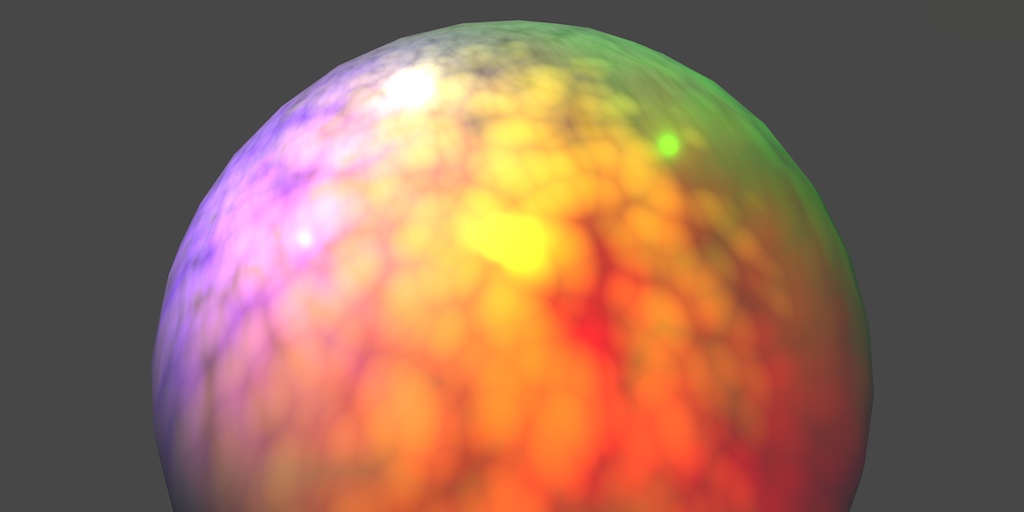
A Unity Rendering tutorial series about supporting multiple lights. Part 5 of 20.
the interior and exterior dont align at all
and I dont know why they dont align and I dont know how to fix it
im gettin it now, i was going about the forwardbase pass all wrong
i thought it was the first 4 of any lights, now im pretty sure its the first 4 directional lights only
or maybe just the first directional light
All that stuff got reworked in Unity 5.
So make sure you're looking at at least that version of docs.
There's macros for light attenuation, and they're aware of light type.

Unity Forum
Hey, currently got this toon shader, but it only uses the directional light right now, which isnt great. I'd like to add point light support too. How...
You can get an idea of what UNITY_LIGHT_ATTENUATION macros do depending on the type of light, from the AUTOLIGHT.CGINC file.
This is a bit old, but https://github.com/TwoTailsGames/Unity-Built-in-Shaders/blob/master/CGIncludes/AutoLight.cginc

GitHub
Unity Built in Shaders. Contribute to TwoTailsGames/Unity-Built-in-Shaders development by creating an account on GitHub.
You can always download the shader source from the repository for your version of Unity. Google is your friend.
Hi everyone (yet again), I have some questions regarding shadows and textures.
I downloaded from github some assets from Sebastian Lague's terraforming video and deleted everything except the cloud part (since I want volumetric clouds that move around a central planet). The problem is that I want to modify the code in order for it to use a 'hybrid' method for generating the clouds (basically generate them trough a base 8K or 16K texture of clouds and then add worley noise on top to add some distortion), so how do I do this? (as well as adding scattering and shadows from the clouds to other objects) Any answers are welcome.
It is pretty complicated and I've tried multiple times to use a base texture to do it but to no avail.
How do I mirror the result of a sample cube map? When I do one-minus the input, the result doesnt mirror, it completely breaks

I noticed I can swizzle the inputs to get weird stuff that is not a rotation, but also not completely broken
I cannot use the reflected cubemap in this circumstance either
it doesnt work, results are wrong
im having a hard time visualizing how you even 'mirror' a cube map

one minusing the inputs causes it to completely futz up
I dont know what math im supposed to do to get mirrored results
You mean you want to get the opposite side of the cubemap for each direction?
No I want to mirror the textures

the 3 inside should be backwards to the exterior one
Hi, I'm very new to using shader graphs and I'm trying to make a water texture. The UV is scaling when i scale up the object with the material, and I want it to tile proportionately. How do I fix it?

it should also be behind the red 3 but thats a different problem I cant fix either

I want to mirror every individual cube here, so that the +/- symbol is opposite side of whats shown here

You likely want negate instead
ah yeah I realized that but didnt realize negate does it in one step

that being said, it doesnt actually do the reflection I want
some of them are rotated, some of them are mirrored, some of them are mirrored AND rotated
maybe some combination of negate and swizzle will work?
I dont know how to solve that and brute force would tkae ages
since there is hundreds of possibilities
Could you remind me why you need a cubemap (or why you need to sample a Texture2D as a cubemap)? Is the cube not UV mapped?

there are two sets of UVs, one is the red exterior and the interior one grey one is constructed from object position math
red one is texture2D interior one is cubemap
I need them to align perfectly with one another, but they don't
as you can see, the back faces are not the same, expected is that every number would show itself but mirrored on the back
But if you could figure out a way to use the same Texture2D for both, that would be better, right?
yes
Can you try this subgraph
I dont want to have two completely separate methods but when i try to actually do stuff to the values, I need them to be in specific spaces

this here requires it to be a cube map to work like that
anyways trying this now

neither set of uvs worked, it turned into slavik pants
what is the expected values passed into the vec3?
im starting to think its just not possible to solve
and that I might have to author two textures per thing
I'm using the Position node (object space)

Basically, these give the same result for me. Though that does depend on the uvs the cube is using, and the layout of the texture


even with a unity cube
did you send me a maybe out of date graph that wasnt saved?
I just noticed your inputs are opposite to mine
dir on bottom,. tex on top, mine is dir on top tex on bottom
I think I did edit the blackboard a bit after I sent it, as I noticed I didn't name them. I don't think I edited the graph itself though. I'll send again just in case
got it working!

both files came in as ".shadersubgrap" and not ".shadersubgraph" dunno why
no difference

Yeah stange, I guess an issue with discord
oh my windows being fucky
wasnt the right file let me do that again

no difference


Don't really understand how this can be different

I'm using 2021.3.7f1
What does the Swizzle node look like in those versions?
fucked, thats what

this is the version where swizzle needs you to open and close it to get options
😬
Yeah thats why, I'm using the new one. You can swap them out for Split->Vector2 though

what are your swizzles set to? Ill replace them with split-vector3
kk doing that
tada it was the swizzle

hey and it just works with the inside out uvs too

let me try using this in my over all graph
call up todd howard because it just works

How did you solve it?
If the water is a flat plane, a good way to handle it is to project the noise in world space, rather than using mesh UVs.
Position node (World) space -> Split and take R and B into a Vector2. Put this in the UV port on your Tiling And Offset.
(Bit more info here : https://www.cyanilux.com/faq/#sg-planar-mapping)
Hi all, I have a question. I'm creating a sub graph for specular lighting, it uses the Normal Vector node to calculate spec. Is there a way I can change to this work with a specific normal map instead of the object's normals?

Not too sure how well I can explain it, but in short, the direction ray is intersected with a unit cube. That's the first custom function - It's required as I realised the direction can be normalised, and we need the intersection point of that cube. (But technically if you just use the Position node this isn't required)
The point on that cube is swizzled and remapped to convert it to UV values per each cube face. The values used for remapping was really just trial and error. It's kinda similar to Triplanar - but as we don't need blending there's no need to sample the texture multiple times.
Instead I used another custom function to combine those UV coords. It also samples the texture, using SAMPLE_TEXTURE2D_GRAD (to prevent those pixellated lines, like the issue you had a few days ago)
how can i get the cameras forward vector in a shader, is there some public variable for it or do i have to pass it every frame?
Thank you so much for responding! I tried what you asked, but its still stretching when i scale the material. Did I do something wrong?

To work with a normal map, you'd sample it (Sample Texture 2D, Normal mode) and use a Transform node (Direction mode) to convert from Tangent to World space. Replace the Normal Vector with that.
If you want to be able to use both options (normal map & mesh normals) you could add a Vector3 property/input and pass the normal in from the main graph.
If you're in 2021.2+ can even use a On Branch Input Connected to automatically use the Normal Vector node when the port is left empty. e.g. https://www.cyanilux.com/tutorials/intro-to-shader-graph/#sub-graph-branch
Transform node! That's what I was missing. Thank you very much.
Hmm It shouldn't stretch anymore. Though it's possible what you're seeing is due to the resolution of the mesh. Instead of scaling the plane, try using multiple planes next to eachother.
THANK YOU SO MUCH! multiple planes next to each other did the trick. You are the best!
Uhh there are methods to extract it from the inverse view matrix iirc. Maybe -UNITY_MATRIX_I_V._m02_m12_m22?
Shader graph seems to use -1 * mul(UNITY_MATRIX_M, transpose(mul(UNITY_MATRIX_I_M, UNITY_MATRIX_I_V)) [2].xyz);
dont know much about matrix math but i should probably get learning
So, I have this horizontally wrapping texture that i'm scrolling with an offset node

and what I want to do
is take the scrolling texture
and apply a different uv map to that output
(basically I'm trying to wobble the scrolling texture a little)
How do I take the output of sample texture2D and apply another UV map to it?
I'm wanting to write a shader that takes a rendertexture, and whenever a certain color is on screen, it flips the normals of every tri on the mesh containing that color.
The goal of this, is to have a rectangular mesh made up of a bunch of triangles, and whenever an enemy appears, it procedurally hides it from view so you only see its triangulated sillohuete. My thought process for the 'certain color' part is bc im assuming it would be easier to detect
can this be done with the shader graph? or will I have to write it in HLSL? or is there a better approach to this overall?
Hey everyone, im in need of some help with I believe would be a stencil shader problem. I am using URP and have no idea where to start, this shader is a custom lit shader on a sprite render component.
How can I make it so the feet dont clip through the floor below? I would post the shader, but its a basic long code, so dont want to spam xD
ive attempted other ways of achieving this, but for the isometric style I believe I need stencils

why would it need to be a specific color for you to invert the normals?
You can try
cameraForwardDir.xyz /= cameraForwardDir.w;
cameraForwardDir.xyz -= _WorldSpaceCameraPos;```
From here https://www.vertexfragment.com/ramblings/unity-deferred-post-processing/#calculating-the-view-direction
If you do that, you'd do it in the vert() function so you can pass it to the frag without having to calc it for every pixel.
Might just be easier to pass it in from C# though, depends on how many material instances you need it on and also you could use a shader global variable to pass it to all of them.function toggleInfoBox(id) { $("#" + id + "-body").toggle(); } Overview Setup Installing the Post Processing Package Using a Post Processing Effect Surface Angle Silhouette Creating the Post Process Component PostProcessEffectSettings PostProcessEffectRenderer Creating the Post Process Shader Reconstructing the Scene Calculating the Vi...
You may want to normalize it.
is there a reason to learn how to code shaders now days ? seems you can do almost everything with shader graph
for when the thing you want to do isn't included in "almost everything"
And I can count up a lot of situations shader graph was not very helpful in getting exactly what was needed 😄
do you have any examples of an effect you had to code ?
Just trying to remember one case it was super easy on coding the shader and a pain in the butt when I tried shadergraph for it. Give me a sec to search my repos 😄
Besides that I had a lot of platform issues where shadergraph was not supported well and I had to simplify the shader a lot so it was working. But trying to find that one example that was super obvious
did you have any issues with oculus ? I'm more of a gameplay dev but started learning shader graph recently
In a recent project there were some issues with shadergraph and a third party plugin (Needle Engine), but that was more a conversion issue of their plugin than it was Unity, but still relying on shadergraph was the problem at the end and a simple shader the solution. But besides that, no, not that much experience on Oculus Dev to talk about its pros and cons explicitly
thnx for the response. I guess ill have to learn it eventually
I would say, go with your known route until you really hit the issue, you can still learn shader coding the tbh. For most parts, you will get away with shadergraph. And if you step into the need of a super custom shader, you will have to give some time to it anyway. cause if you do not code shaders constantly, you might forget half of your knowledge over time anyway
yea we dont really need complex shaders so far. Just simple effects like dissolve, ect...
Thats absolutely doable with shadergraph, so I would go with that first. Optimise later if needed 🙂
hey guys sorry for asking, but im building a 2d game and wanted to add a fog, I did create and it did work, but it drops 10fps for some reason, can somebody pls tell me why it drops so much?

Because transparent shaders are like one of the most performance intensive things you can have. Especially when the fog is all over the screen, it has to recalculate everything all the time in terms of depth calculation and what not
Is there is any way to make it more performant?
Why not just tryout particle systems or a post processing effect. There are many ways. Does the fog need to be 3D and depth related?
What are you using your shader for? Like where do you put it in?
Its 2d, so its pretty simple. but i guess ill need it to do through particle system, Thank you twentacle!
How do I take the output of sample
actually, ive completely removed the alpha joint, but it still drops 10fps, maybe its something else that causes the fps drop?
Can you show your scene/game view, where and how is the shader being used?
Is this "fps drop" in game, or just scene view?
here it is

In game view
And if you take away the alpha and make it opaque, it still drops?
yep
ive kept it at 1
at 1? Like alpha = 1? make it opaque, no alpha channel at all and see what happens

Make your shader opaque
I did, i set in alpha 1


If you want to avoid the overdraw, one way might be to move the fog calculation to the same shader(s) used by the rest of the sprites/scene. Assuming that's not the built-in ones.
You can sample the noise using Screen Position rather than UV0 to make sure it appears the same.
Oh, okay you got sprite unlit shader here. Well I think its a bad idea to have a huge sprite all over the screen that keeps updating the whole rendering cycle. Try to use particles first, that might already give you what you want
So just drop the shader? alright, thank you for helping
Thats the only shader I have in this scene.
I would drop the shader, yes. You just force Unity to rerender everything, that might be the issue. Just try to disable the gameobject with the sprite and add a simple fog with a huge size and maybe 4 particles or so and see what that costs on performance
Alright thank you for helping out, and thank you @regal stag too
Is simply popping my computebuffers into OnApplicationQuit() for .Release a good enough solution, or rather what I should be doing?
I would release them when they are not needed anymore, so OnDestroy maybe?
Well yea potentially that could be needed but i otherwise i only release them on level change.
you should release them to resize them right?
cause you have to remake the buffer
Which will call OnDestroy too I think, so nthat could be a save place
You release them to free up memory, at least from my little knowledge about it
Hey there. I have a shader-based system to procedurally instance large numbers of objects through Graphics.DrawMeshInstancedProcedural/Graphics.RenderMeshPrimitives. This currently works on Built-In and I'm now migrating it to URP. Anybody have any pointers/tutorials/sources on how to set up this kind of instancing on URP? Resources are pretty scant.
You mean the same code doesn't work in URP?
The code itself probably does, but given that the shaders themselves need to be migrated to URP there's different includes, etc.
For the record, the shaders is built with Amplify Shader Editor, but that doesn't matter too much, since it's mostly the right shader includes I'm after. 😛
It seems to me that UnityInstancing.cginc and UnityInstancing.hlsl are very similar. I don't think there's anything different you need to do in the shader to support instancing.
Yeah, I'm staring at those two right now too. Currently doing a quick test run with shadergraph. Do you happen to know if there's any setting to "get" it to include UnityInstancing.hlsl? It doesn't seem to do so by default.
Made a hand-written version of that shader and did include UnityInstancing.hlsl but the instancing id always seems to return 0, which implies the UNITY_ANY_INSTANCING_ENABLED keyword is false, which UnityInstancing should turn on, from the looks of it. Deep rabbit hole. XD
I haven't used DrawMeshInstancedProcedural before, but have used DrawMeshInstancedIndirect which I think is basically the same thing? (specifically I used it to render quads for grass)
To get shader graph to support that I used a boolean keyword, PROCEDURAL_INSTANCING_ON and a custom function to add the instancing_options pragma. Have some info on it here : https://www.cyanilux.com/faq/#sg-drawmeshinstancedindirect
Nice! Gonna check that out. Thanks! And yeah, this is a similar system for rendering grass and similar terrain details. To my knowledge, the difference DrawMeshInstancedIndirect and DrawMeshInstancedProcedural is that the former still allows you to pass data that the shader can use, whereas the latter is for cases where the shader can procedurally figure everything out without extra buffers.
In our case the data list for placement/rotation became so huge (file-size) that it became unwieldy to serialize in any "Unity-like" way and by far the most efficient storage on disk was as a data texture. And, you know, once it's a texture, might as well pass it to the material directly...
Dang, just spent five minutes trying to discover where on earth to find those settings for that keyword. XD
Hey guys
I made a water shader (URP) but I realized it is obstructing canvases (as shown in the screenshot)
(The canvas is set to World Space)
I googled the issue and found no help because the keywords are very similar to another issue that's completely unrelated to mine

Do I have to manually draw the canvas on top of my shader? or there's an option I'm missing
I'm getting really close to achieving the effect I'm aiming for, I just need to figure out how to make the black pixels transparent?