#archived-shaders
1 messages · Page 29 of 1
damn
Im new to shaders so I just followed a guide and the guide used PBR graph and I did it in Lit Shader graph
I would assume this is just due to the resolution of the texture. You could add a Tiling And Offset node to the UV port on your Moss texture sample to adjust the tiling/scale.

So, this system essentially outputs the vertex positions using the UV node instead?
Yeah
Ok, so when I'm making a shader that works with the system I just use the UV node instead of the position node? But normals and other data can still be used with the same nodes?
Pardon my lack of understanding lol
No, Kinda. There's a Bake Shader Vertex Pos subgraph provided in the github repo that you'd attach to the Position port in the master stack (vertex stage).
But since we change that position, if the graph uses the Position node in the fragment stage it's now different. If you need the original position, you'd need to pass it through a Custom Interpolator. (See link above if you don't know what that is)
Perfect, and I actually just saw you have those exact directions on the github 🫣. Wouldn't I need to attach something to the normal vertex port if I wanted to access those aswell?

Because you need to change the import settings to be a normal map, it's just how unity assigns channels to normal maps it's weird (e: actually it's not weird its to squeeze more bit depth I think)
No, Shader graph already handles passing the vertex normals through when nothing is connected.
Ok, well this looks like a great tool, thanks again! Now I just need to figure out how to use it at runtime. 🤔

like this?
Looks right
cause its still pink
Try using a normal map node
You'd also want Type : Normal on the node when sampling normal maps.

Trying using the "Normal From Texture" node
Pretty sure it's meant to look like that
not really

in the tutorial its like this, but its from 2019...
so might be outdated
Well, the tutorial isn't sampling with Normal type, so it's wrong. Maybe they change it later.
@regal stag The shader bakes fine like this:

But not like this: (E: nevermind, I just wasn't baking using the renderer dropdown.)

If the results look fine on your mesh they probably are, sometimes the previews can look different
Is there a way to force compile for at least d3d11.1 instead of d3d11?
I wanna get rid of these warnings

Using shader graph, how do I get the 2d position of the vertex position on a plane? A plane defined by origin and normal?
How would I make a sprite/material that you can see through walls?
Like ESP in games or similar.
anyone
Is the world generator based on marching voxels?
Terra Nil

hi how can i make a optimized stadium grass?
Probably not
I would presume 3D tilemaps
My voxel game is like minecraft. I have optimized it, combine faces if some conditions are satisfied
In the above, there is no optimization? only 3d voxel tile map and then combine them to get a chunk?
If, I want something like this game, my way does not work?
For example, if my land is flat, it has really less faces

Pure cubes. :/
If I want bending in edges
It looks like the example here doesn't have any volumetric information, so voxels or marching cubes would not be necessary
The terrain seems to have a ground type with height variants for each tile, and an object placed on top
A 3D tileset system matches terrain meshes so the tiles appear seamless
This is not related to shaders though
I mean they do not have specific optimization for these tiles? The number is huge
Each tile has 6 faces, 12 triangels
Only place them and then combine to one chunk or mesh?
there is barely "any" tiles on the current screen compared to what GPUs can handle
also, this is the wrong channel
#archived-code-advanced would be a better place for this
OK, thanks
anyone have any idea on how to change a custom cg shader to urp shader ?
Shader "Custom/Terrain" {
Properties{
testTexture("Texture", 2D) = "white"{}
testScale("Scale", Float) = 1
}
    SubShader{
        Tags { "RenderType" = "Opaque" }
        LOD 200

        CGPROGRAM
        // Physically based Standard lighting model, and enable shadows on all light types
        #pragma surface surf Standard fullforwardshadows

        // Use shader model 3.0 target, to get nicer looking lighting
        #pragma target 3.0

        const static int maxLayerCount = 8;
        const static float epsilon = 1E-4;

        int layerCount;
        float3 baseColours[maxLayerCount];
        float baseStartHeights[maxLayerCount];
        float baseBlends[maxLayerCount];
        float baseColourStrength[maxLayerCount];
        float baseTextureScales[maxLayerCount];

        float minHeight;
        float maxHeight;

        sampler2D testTexture;
        float testScale;

        UNITY_DECLARE_TEX2DARRAY(baseTextures);

        struct Input {
            float3 worldPos;
            float3 worldNormal;
        };

        float inverseLerp(float a, float b, float value) {
            return saturate((value - a) / (b - a));
        }

        float3 triplanar(float3 worldPos, float scale, float3 blendAxes, int textureIndex) {
            float3 scaledWorldPos = worldPos / scale;
            float3 xProjection = UNITY_SAMPLE_TEX2DARRAY(baseTextures, float3(scaledWorldPos.y, scaledWorldPos.z, textureIndex)) * blendAxes.x;
            float3 yProjection = UNITY_SAMPLE_TEX2DARRAY(baseTextures, float3(scaledWorldPos.x, scaledWorldPos.z, textureIndex)) * blendAxes.y;
            float3 zProjection = UNITY_SAMPLE_TEX2DARRAY(baseTextures, float3(scaledWorldPos.x, scaledWorldPos.y, textureIndex)) * blendAxes.z;
            return xProjection + yProjection + zProjection;
        }
void surf(Input IN, inout SurfaceOutputStandard o) {
float heightPercent = inverseLerp(minHeight,maxHeight, IN.worldPos.y);
float3 blendAxes = abs(IN.worldNormal);
blendAxes /= blendAxes.x + blendAxes.y + blendAxes.z;
            for (int i = 0; i < layerCount; i++) {
                float drawStrength = inverseLerp(-baseBlends[i] / 2 - epsilon, baseBlends[i] / 2, heightPercent - baseStartHeights[i]);

                float3 baseColour = baseColours[i] * baseColourStrength[i];
                float3 textureColour = triplanar(IN.worldPos, baseTextureScales[i], blendAxes, i) * (1 - baseColourStrength[i]);

                o.Albedo = o.Albedo * (1 - drawStrength) + (baseColour + textureColour) * drawStrength;
            }
        }


        ENDCG
    }
        FallBack "Diffuse"
}
here is my code
Are structs with arrays not allowed in HLSL? It should be within the size limit but it still wont let me.


Hi everyone. I'm having an issue with my bg, some how the entire background of my game turn into this purple color, what was the cause of this?

A fixed size array is not the same as a managed array. C# has fixed size arrays, but that needs unsafe and I don't know how it plays with NativeArray:
public unsafe struct Brickmap
{
    public fixed uint voxelArray[512];
}
The Unity.Collections package also has special list types that are a fixed size
been banging my head at this problem for 2 days now and turns out, i have no clue what i'm doing lol. I'm trying to create a 3d noise based on a gradient that would wrap around (or triplanar) an object...as for the gradient, the whiter it gets, the less noise there is. Any ideas?
@low lichen hmm alright. i guess if the buffer supports really high count values i could just store them as a 1D array and treat every 512 entries as the next array


this is what i have :/ essentially i would like to be the more shadow, the more noise there is i guess. If anyone can help maybe point me in the right direction. Thank you 🙂
B E A N
The problem is that you're never going to get any noise in the shadows because you're multiplying the noise by the NdotL, which zeros out the noise in the shadows.
hmm even removing the NdotL portion still give me the same result
i get these 2 errors when trying to install the unity toon shader trough the package manager. any ideas on how to fix them?

Use the NdotL term as a lerp
Based on what you said your looking for...
Lerp(noiseTerm, white, nDotL)
I'm watching a bunch of tutorials...not gonna lie, I'm not understanding 10% of all this 😂
But I'll try it out 🙂
Lerp(a, b, t)
So basically lerp is a linear interpolation, it basically means that as T gets closer to either 0 or 1 it will fade to a or B
You use the NdotL shading gradient you currently have as your T term
So things that are in shadow are noisy
Lerp i get.. n dot l..no clue
Shouldn't have skipped math class (if this is even math) haha
N dot L is your lighting gradient you curently have, its the dot product of your normal direction and your light direction. Its the light shading you have already on your cyllinder and sphere
I see...that makes sense
You are already computing that in your shader graph, its your diffuse light group
So n is for normal and l is for lighting
Gotcha
Thank you for that explanation. Wish these tutorials just go over the basics rather than drag a bunch of nodes and magically things happen
https://www.youtube.com/watch?v=BFld4EBO2RE&ab_channel=InigoQuilez this video is pretty good
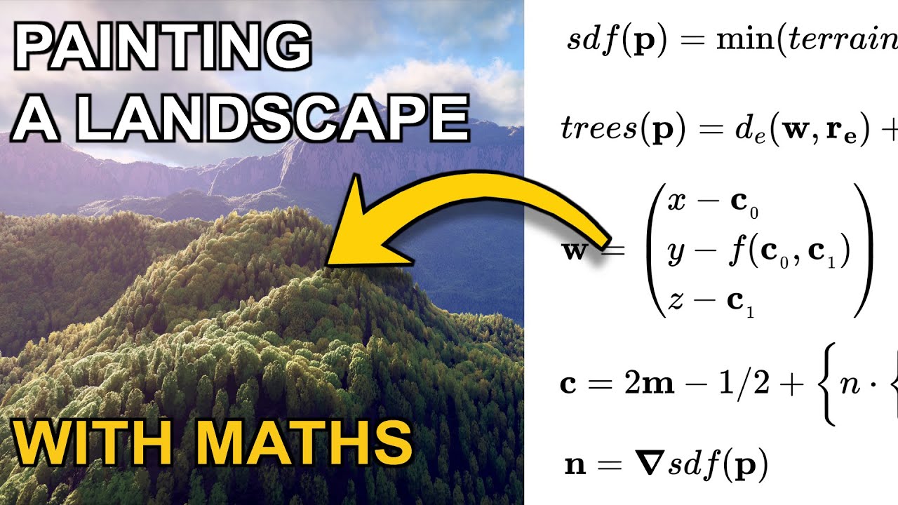
Today we are painting a landscape using mathematics.
Support this channel: https://www.patreon.com/inigoquilez
Buy this painting in a metal, canvas or photographic paper print: https://www.redbubble.com/shop/ap/39843511
This is the link to the real-time rendering code (that you can edit yourself live) for the painting: https://www.shadertoy.com...
Use compute buffers (structured buffer).
2 cents.
@meager pelican 👍 yeah i tested it and they supported way big arrays. should be fine.
Does anyone have any idea how I might address this weirdo circle drawing thing here? I'm just trying to raymarch and read some voxels to a quad. https://pastebin.com/TmaJqG3R
Thanks. I'll check it out 🙂
Unsure if this is the right spot for this question, but when using the decal shaders in Unity URP, is there any possibility for forcing them to respect transparent geometry that came before it?
I have a decal sent to render on Transparency+1 (3001) and some water on Transparency(3000). In the water shader in shader graph, I enabled ForceDepthWrite on to write to the depth buffer, but the decal still is on the sand underneath the water. Upon googling it, I have found this https://forum.unity.com/threads/urp-decals-on-transparent-surfaces.1273913/ as a kind of hacky way to get it working, but is there anything I can use? I am using Unity 2022.2.1f1 with URP version 15.X

Unity Forum
I'm trying to figure out a way to force Unity's URP Decal Projector to also influence transparent objects.
I do know that URP Decal system does not...
I'm trying to create a GPU based solution for modifying textures at runtime. My issue right now is that I want the shader to have access to mesh data like vertex position, normal, etc. whilst still working in texture space. So I suppose my question is, how would I convert texture coordinates to a mesh triangle index which I could use to interpolate UV values, normal values, vertex positions, etc.
E: One way I've seen people do it is by looping through all triangles in the mesh for each "texture sample point" and seeing if that point is within a UV triangle. I know it's being done on the GPU but I would love a more computationally cheap way than to iterate through thousands of vertices for millions of pixels.
The method I've been using is to draw the mesh with a vertex shader that uses UV as the position, essentially UV unwrapping in the shader. Then you have the texture you want to modify as the render target and now the fragment shader will be outputting to the correct pixel while having access to all the vertex information (and interpolated in between)
I think I've tried that, but I'm getting these dark seams around the UV islands, do you know some way I could fix that?
Actually let me send a picture
This is pre bake:

and this is after:

Also the solution I'm using right now which I didn't make, requires me to wait several seconds for some reason before baking, I can send a picture of what happens if I don't wait long enough (if you'd like)
Conservative rasterization is one way to avoid that problem, but that isn't supported on all platforms.
https://docs.unity3d.com/Manual/SL-Conservative.html
Can this be done through shader graph?
Doubt it
There's also a more expensive method, which is to inflate/dilate the texture afterwards, like this:
https://github.com/sneha-belkhale/shader-bake-unity/blob/master/Assets/Shaders/Dilate.shader.shader
GitHub
Baking run-time shaders into textures in Unity. Contribute to sneha-belkhale/shader-bake-unity development by creating an account on GitHub.
If you're doing this through a custom render pass, you can enable conservative rasterization there:
https://docs.unity3d.com/ScriptReference/Rendering.RasterState.html

What if instead I just got the closest position along the closest UV edge? And just calculated the entire texture all at once?
Also I'm still interested in exactly how the built in shaders convert 3d space to uv space or vice versa
I don't know what that means.
Basically if I detect that a pixel is not within any triangles, I just get the closest point to the closest triangle, which would be an edge, and do my 3d-based calculations based off of that? It would be similar to the dilation thing but presumably more efficient, It would also ensure the dilations wouldn't overlap
That would require a totally different approach than UV unwrapping
With the UV unwrapping approach, the pixels outside a triangle simply won't be drawn, so there's no shader being run on it.
Sorry I meant all of this would be done in uv coordinates, with the uv unwrap
Yes I would have to possibly alter the way the triangles are obtained from UV coords, which is why I still think it would be useful to know how unity does it
I will draw a little picture
Unity is never calculating what triangle contains a UV coordinate. That doesn't even make sense because any number of triangles can contain the same UV coordinate.

Well then how does it convert between UV and 3D coordinates?
I did read online that it actually starts with the 3D coordinate, and then converts that to screen space
Every vertex has a UV coordinate. In normal rendering, the vertex shader places each vertex where it should be relative to the camera. Then the rasterizer figures out what pixels are occupied by triangles and interpolates the data from the 3 vertices and gives it to the fragment shader.
But by ignoring the 3D positions of the vertices and just placing each vertex by their UV coordinate, what you'll get is the same UV unwrapped view you'd see if you open the model in Blender.

I think I get it, so it basically recompiles the data for a "Fragment" shader to use?
Which is useful because the shader uses UV coordinates when texture baking right?
Which shader are you referring to?
Basically when you use the Blit function on a render texture using a material as an argument, the data is sent to the render texture using uv coords?
I'm thinking I might implement my own form of rasterization, if necessary
It sounds like you're missing some critical pieces of information about how 3D rendering works, which would make all of this a lot harder
You're probably right, but for starters, what if I just calculated the square bounds of each triangle, assigned each pixel within those square bounds a "triangle start index", then iterated through a collection of pixels, using their triangle start index to get all of the info I need. From my limited perspective, the only downside to this would be the inefficiency of using whole squares (which may overlap) to correlate the pixels to their respective triangles, it would also cause some duplicated effort on pixels which are within the same square bounds: but an article read or two should replace the missing knowledge there right, giving me a better solution rather than square bounds? I don't need to worry about lighting or anything like that as I'm only modifying the textures.
I'm not sure how you would handle overlap between the square bounds. But you should understand that the UV unwrap method is basically no more expensive than rendering that mesh normally, which is super cheap because the GPU is hardware accelerated to handle triangles and rasterize them. Your method's performance will depend entirely on your implementation. It sounds like something that can be done with a compute shader, but is definitely going to be slower than the GPU's built-in rasterizer.
Ok, do you think it would be more efficient if I just inflated the uvs before baking? That would get rid of the seams. I've been able to bake the textures instantaneously before so I'm sure i could get rid of the delay.
Before I answer that, could you give me a quick explanation of why you need texture baking?
Sure, I want to have effects like blood splatter, dirt, rust, wetness, cuts, burns, pock marks, you name it. But this is all too much to do in a shader like in this video:
https://www.youtube.com/watch?v=A-P0llMckSw
So I thought I'd just have a standard lit shader, and modifying the texture inputs to generate the results I want.

Big systems require big explanations... I hope you've got a drink and a snack because this feature-length Development Log doesn't slow down!
In this video we take a look at my last month of work, creating a robust character customization system so that Prismatica can be full of unique and colourful characters. This system also allows for indivi...
Interesting looks like he does exactly what you're talking about in this video:
https://www.youtube.com/watch?v=yjki_Lr92Pg

Hello hello! In today's Prismatica DevLog we take a look at my latest experimentations for drawing damage and blood to characters! The way we do this is inspired by Ryan Brucks' world space unwrap method for skeletal meshes.
The reason I've gone with a Render Target approach as opposed to using decals is because performance with decals scales ...
There is another workaround I can think of which would be cheaper and potentially more accurate than inflating the texture after each draw. That would be to pre-process the mesh by calculating the inflated UV coordinate of each vertex and storing that in another UV channel. Then the unwrap shader can use that UV coordinate instead and everything will already be inflated.
This asset does something similar to that for rendering outlines, but inflating the vertex position instead of UV coordinate.
https://assetstore.unity.com/packages/tools/particles-effects/quick-outline-115488
Use the Quick Outline tool for your next project. Find this and more particle & effect tools on the Unity Asset Store.
Source code for that asset is here:
https://github.com/chrisnolet/QuickOutline/tree/master/QuickOutline

GitHub
Unity asset for adding outlines to game objects. Contribute to chrisnolet/QuickOutline development by creating an account on GitHub.
Could I do this automatically in unity, like creating some sort of custom FBX importer? Also I'm assuming inflating the triangles from their center is fine even though there will be some overlap?
I will definitely take a look at these
Sure, you could do it in a custom model importer. QuickOutline does it at runtime on Awake, with the option to pre-compute, which is just serializing the mesh modifications on the Outline script of that object.
Doing it in an asset importer is definitely cleaner, but also eliminates the possibility of loading models at runtime, unless you also include a runtime version of the preprocessor.
Well if I modified the assets wouldn't they all have the data when I instantiate them?
When I say loading models at runtime, I'm talking about like modding support. Unity has an asset importer scripting API, which will let you automatically modify models after they have been imported by Unity, but that only works in the editor.
That's what I was talking about when I said "custom model importer"
Ah true
Maybe I'll just make some sort of static class that can check it both in the editor and at runtime
Thanks for all the info you've given so far, I think I only have one more question. If I want to get the original position of a skinned mesh vertex in a shader before displacement, would it be necessary to say, bake that into the vertex colors the same way I would with the UV inflation? Or is there some other way I can access it without having to do that?
That won't work when multiple triangles share the same vertex. The inflation direction will be different for each of those triangles, so you should only modify the edge vertices.
Is there any built in way to gather edge vertices, otherwise I know a way I can do it myself but wouldn't want to duplicate any effort.
Not that I know of, but I've seen people here using C# libraries for that, like this one:
https://github.com/gradientspace/geometry3Sharp

GitHub
C# library for 2D/3D geometric computation, mesh algorithms, and so on. Boost license. - GitHub - gradientspace/geometry3Sharp: C# library for 2D/3D geometric computation, mesh algorithms, and so o...
Alright perfect. I think I will stick with the uv unwrapping solution, but will inflate the UVs before hand and find some way to get rid of the delay.
If you have a reference to the Mesh the skinned mesh renderer is using, that will always be unmodified. You can get the positions there and upload to the GPU yourself, but you can also get a reference to the vertex buffer that is already uploaded to the GPU with Mesh.GetVertexBuffer. It's just a bit more difficult to read from, because it contains all vertex attributes, not just positions, so you need to know the memory layout to know where the positions are. The layout is accessible through Mesh.GetVertexAttributes.
Alright, thanks again, and I think I'll use an asset postprocessor for the fbx thing instead
Hey! Trying to use this one shader from Unity, but im not able to get it render light cookies, is there any way i can get support about it?
https://docs.unity3d.com/Packages/com.unity.toonshader@0.8/manual/index.html
I don't think the answer "yes" will satisfy you, but the question doesn't really go into detail. Can you specify?
My grass using a shader from the URP terrain demo does not show up in builds, only the editor. Any ideas? Uses Shader Graphs\TerrainGrass
I have a hex sprite -- standard white hex
I want to apply a texture to it, (vegetation texture)
how do I do that


I would say...
https://docs.unity3d.com/Manual/class-SpriteMask.html
or make a shader (this is easier with shader graph).
If anyone knows how to use decals I would greatly appreciate any info for this still 🙂
Good lord, it worked! Thanks!!!!
np, glad to hear it
one question though, i would need a seperate renderer for each texture then?
How are you masking the terrain textures? Do you have one big texture and are just masking a small area?


How does that shader turn the grass texture into a hexagon?
You're basically just sampling the same texture
So you don't have the hexagon shape yet?

I think your initial problem was that you were using the lit shader, I think there's some sort of built in sprite/2d shader. Your best bet to solve all of your problems would be to just quickly run through a tilemap tutorial, if you're using the builtin unity tools it should all be pretty easy, just make sure you're paying attention to what kind of shader you're using.

that should also allow you to use separate textures for separate tiles
here are all the sprite shaders

If i use the default unlit one
the texture is not applied
ok so i made like a small edit to my shader and it completely broke and it wont give me a single error hinting as to why
Shader "Lighting/Splatter"
{
    Properties
    {
        _Albedo("Albedo", 2D) = "white" {}
        _Color("Color",Color) = (1,1,1,1)
    }
        SubShader
        {
            Pass
            {
                CGPROGRAM
                #pragma exclude_renderers d3d11
                #pragma vertex vert
                #pragma fragment frag
                #include "UnityCG.cginc"
                struct appdata {
                    float4 vert : POSITION;
                    float2 uv : TEXCOORD0;
                    float3 norm : NORMAL;
                };
                struct v2f {
                    float4 vert : SV_POSITION;
                    float2 uv : TEXCOORD0;
                    float3 norm : NORMAL;
                };
                fixed4 _Color;
                sampler2D _Albedo;
                float random(float2 uv)
                {
                    return (sin((uv.y)*5000) - 0.5)/2;
                }
                v2f vert(appdata IN)
                {
                    v2f OUT;
                    OUT.vert = UnityObjectToClipPos(IN.vert);
                    OUT.uv = IN.uv;
                    OUT.norm = IN.norm;
                    return OUT;
                }
                fixed4 frag(v2f IN) : SV_Target
                {
                    fixed4 pixColor = tex2D(_Albedo, IN.uv);
                    float lightfactor = dot(float3(0,-1,0) * -1, UnityObjectToWorldNormal(IN.norm)) ;

                    return ((pixColor * _Color) * lightfactor) + random(IN.vert);
                }
                ENDCG
            }
        }
}
I don't know, but a tutorial will know, just run through that and do everything it does.
Sorry if that seems like a bit of an unhelpful response but it's the best I got (and will probably work)
You have been of great help, dont worry
As for the tutorial, you mean the one on unity.learn?
Any tutorial, the more specific for your needs the better, you could look up a hexagon tile map tutorial
Ok, will try and find one, Thank you very much
np, good luck
Yea, I think you can only have one material per sprite renderer
Just use whatever the built in solution is if you want multiple terrain types: https://docs.unity3d.com/Manual/class-Tilemap.html

Yea, I get that, but I was hoping you could just add a material to a sprite.
otherwise, you would have to manually draw a desired texture(terrain) for a sprite
If the goal is to have grass textures masked in the shape of a hexagon and then place those tiles in a tilemap, this should accomplish that.
Yes, but you will need a seperate tilemap for every different texture/terrain
I don't think so, I think that's what adding tiles are for. Im pretty sure the built-in solution has someway to different textures on the same tilemap
dont see it man

Those tiles already have their terrain drawn onto them
What I am trying to do is add a texture to a blank sprite,
Why do you need to do that?
Better variety in sprites, it is easier to find 1000+ textures than it is to find a sprite with a specific texture
if you go on the asset store and look up 2d terrain sprites, not alot of options
but if you look up 2d textures --- WAYYYY MORE
Sprites are a usage of textures
You can make sprite assets and assign the 1000+ textures to them

You click that


You're looking at the inspector for the texture not for the sprite

my bad, it looks like it's even easier than I thought, simply change the texture type of your 1000+ textures to sprites
but you may want to check here: https://docs.unity3d.com/Manual/Sprites.html
and also here: https://docs.unity3d.com/Manual/Tilemap-Hexagonal.html


You should probably recreate your tilemap as a hexagonal tilemap if you haven't already, the only other potential useful thing I could mention that would help you down the line is a sprite atlas (which is one way to create a tileset). I think google or somebody else in this channel will probably help you more because tbh this is a bit out of my range of experience. 🤷♂️
lol, yea, you helped me alot though
it seems if i want to create a hex sprite out of a texture
I was to manually outline the hex in the sprite editor
or just create a hexagonal tilemap, try doing that before converting all your sprites


I really think a hexagonal tilemap tutorial would be helpful, worst case scenario you just use the sprite editor and maybe use some sort of importer preset if necessary
ive seen those already
and what did they tell you?
We are close, all that is needed now is to modify the texture into the shape we need
try the sprite editor idk :/
we can do that, ive tried it, but we have gonna have to do it manually
for every texture...
You could duplicate the sprite asset whenever you need to make a new one, then just override the image file in file explorer, that or look into some sort of asset post processor
Asset workflows and such are just as much of a problem to solve as making the game itself
indeed
cant even copy outlines between sprites
smh
There's probably a way, if not one that unity has built in then one you can code yourself
you create your own outline, but it wont be thesame across multiple sprites, since you cant copy and paste them

well like I said you can at least copy the assets
you could also try shift selecting and editing that way
you cant even do that
each shape is tied to the texture and cant be edited or deleted
copy the texture asset I mean
same to you
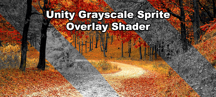
Hello, i'm trying to figure out how to make a grayscale overlay for UI. Here is the shader graph.
So far i only managed to make a grayscale effect for an image itself, but that is not enough since i have other elements in the object like text with sprites (TMPro) and other images (example given). That's why i thought about having an overlay image that grayscales UI elements under it.
I'm pretty new to shaders, so i am at loss what to do. Does anyone know what am i missing?


If this is to symbolize non interactable UI elements consider using things like canvas groups and interactable
That way you can set specific colors to be used on the elements are disabled
and as I recall that works on TMP as well
As far as shaders are concerned making custom shaders for TMP is pretty hard as I recall.
But someone else might have better experience with that
I usually just avoid it when possible
@charred dock thank you for the answer, i am using canvas group, but intractable toggle effects only one image, if i'm not missing anything
meanwhile i have an object with multiple children that need to look grayscaled when disabled
Ah, right it doesn't really become the same effect with colors anyway
@prisma haven https://hastebin.skyra.pw/ezilamikaf.cc
That's a TMP shader that does the same as yours
Based on TMP_SDF-Mobile.shader
oh, thanks a lot!
Put it in the same folder TextMesh Pro/Shaders
Basically the only thing that's changed is line 232
which does the same as your shader graph (I couldn't see exactly what you multiplied with for green so I set it as 1.2, feel free to change that)
c.rgb = (c.r * 0.39 + c.g * 1.2 + c.b * 0.10).xxx;
i'm just trying out different values
but thanks for the help
If you are unfamiliar with shaders in code form what the last .xxx part means is take the same value and make it into a float 3 (just like the combine node in your shader)
ah, i see
yes, i have a very poor knowledge of coded shaders, mainly the reason why i'm using shader graph
Yeah, it's really nice that shader graph makes it a lot more accessible
Usually you would expose your 3 values and set them from a script. All elements will simple have the same shader and you handle it from script how ever you like. That way you can even lerp the values for a nice transition animation. Im mot sure if your overlay idea is even doable
thanks, i'll check it out
in regards of overlay thing it was possible
Nice! How did you do it ?
oh no, it's not mine, it's from here, but i didn't manage to make it work
https://www.unity3dtips.com/unity-grayscale-shader/
Transparent Unity grayscale shader which renders everything behind a target object mask in grayscale. Allows for black & white UI shader effects and more!
Ah it uses a grabpass
ye
Are you on urp or hdrp perhaps
urp
Yeah grab pass doesnt really exist in the new srp's thats why it wont work
yes, i saw that in the comments, there is also an alternative solution posted there
Unless you really need it to work as a dynamic mask I suggest simple exposing your parameters and setting them from script
yes, i was planning to try out your suggestion
thanks for the help!
Am I completely wrong in how I multiply this direction by the camera matrix? I am inputting cam.cameraToWorldMatrix into _CameraMatrix

the results are so strange. Angles feel wrong and it's like things invert into themselves
in a compute shader
I'd like to read more about the helper functions (ie UnityObjectToClipPos) available in Core.hlsl. Does anyone know where these are defined? I've had a look at Core.hlsl and Common.hlsl but can't seem to find much
UnityObjectToClipPos is defined in UnityCG.cginc. The SRP equivalent is TransformObjectToHClip, which is defined in SpaceTransforms.hlsl
Got you! Was wondering how this was passed through Core.hlsl - just had to check out Input.hlsl.
Also, SRP vs URP - I've read that URP is essentially the "new" pipeline Unity will be pushing forward. Is this the case? Should I be continuing to work with URP?
is there a way to assign a variable in shader graph and then reuse that same variable elsewhere with another node? like wireless nodes 
SRP (Scriptable Render Pipeline) is what powers the new render pipelines URP and HDRP. SRP has a common shader library shared between URP and HDRP, which includes SpaceTransforms.hlsl.
And yes, Unity is pushing URP as the replacement for the built-in render pipeline.
Not built-in, but I have an editor script which adds that feature (and a few extras) : https://github.com/Cyanilux/ShaderGraphVariables
oo neat
That makes so much sense. I kept confusing SRP with the built-in render pipeline 😮
Yeah, some people call it the standard render pipeline, which can be confused with SRP. It's also sometimes called the legacy render pipeline.
I'm trying to create a flicker effect, whereby the object "glitches" every set period of time. Currently I've got this:
float4 frag(const v2f i) : SV_TARGET
{
    float3 disp = SAMPLE_TEXTURE2D(_DisplaceTex, sampler_DisplaceTex, i.uv);
    disp = ((disp * 2) - 1) * _Magnitude * (round(_Time.y) % _Interval > 0 ? 0 : 1);

    half4 sample = SAMPLE_TEXTURE2D(_MainTex, sampler_MainTex, i.uv + disp);
    return sample;
}
The flicker is working fine, however there's no way to control how long it flickers for (it's always a second, because of my rounding of _Time), and it also relies on an ugly ternary. How could I improve this to have the flicker duration controlled by a property, and without using the ternary?
Trying to get into the habit of writing shaders without relying on conditional logic 🙂
Why is render texture + raw image doing this?

RT is not getting cleared
Is there any way I can clear it each frame without having to write a new script?
check camera clear flags
Can I do that through the editor?
Yes
Is converting types (float to half, half to float, fixed to float, etc.) time consuming?
I mean is it worth storing some fields as half or fixed in input/output data while they are converted to float in codes?
time consuming? No.
saving data with smaller types can save significant memory
So,
float w=col*_factor+value while col is fixed3 but _factor and value are float/half
float w=col*_factor+value all are floats
Both execution time is equal?
or the difference is negligible?
not equal
negligible yes
Depends on the platform.
Desktop class GPUs pretty much convert everything to a float. lol. You don't know it, but it does that internally. Mobile, OTOH, will use smaller data sizes. One of the big concerns is memory bandwidth. You can get more data throughput by using smaller-sized variables, thus reducing total traffic on the memory bus. So it's not just storage (which matters too) but also throughput in bytes-per-second. And mobile platforms use shared memory with the rest of the device (and cached memory too, so smaller = more cached stuff).
So it's not only the amount of time it takes to convert a type, but also how much of that type your shoving across the bus. Use case, and the when-where-how matters as much as the need/no-need for conversion.
You have to test it out, benchmark it. Every use case is different.
For a 0:1 ternary, where you need to make a decision based on some expression (that you'd evaluate anyway, regardless of eliminating the ternary) it's not worth worrying about 99% of the time, IMO.
Why is this? if these kind of ternary’s are fine, why is branching with more complicated logic such a performance issue?
The reason is that due to how GPU's work, there's multiple processors running in parallel all executing the same code in LOCK STEP.
So if some "pixels" are one condition (true side) and some are the other (false side) they ALL have to step through BOTH SIDES...each are masked off where they don't apply.
So "more complicated logic" = more time to do BOTH SIDES.
Basically with a conditional you get the performance hit of BOTH SIDES unless the condition is the same for all cases, like when you pass in a bool-flag for the entire shader. If they can ALL skip over it, they generally will.
But the cost of doing both (var =1 and var = 0) is insignificant.
Genrally, it is better to use a texture for random noise or implement it with sin, dot,frac?
What about if it is perlin noise not a simplex noise?
I converted it to lerp
Just wondering, how would i set variables defined in a custom function .cginc file on a shader graph? Thanks
Thanks for this breakdown, i suspected it was along these lines but I’m not familiar enough with how GPU’s work to know. This is a great breakdown! 😄
Hello, anyone know if there's a way to disable support for light probe proxy volumes in shaders on built-in RP (Unity 2021.3.16)? It introduces an unwanted extra sampler in almost all shader variants. It seems to be controlled by a keyword set from the Graphics Tier, but I don't want to disable it project-wide, just for this shader. I've found some threads indicating there should be keywords to exclude it, but none of them seem to have an effect.
To answer in short: nope(IMO). Because if you are using unity's shaders, the calculation will be done for GI. Now you need to find where that hlsl/cginc file is and then find the keyword. Even if you find the keyword and you disable it, it will be disabled for all the shaders using that HLSL/CGINC. But, if you are keen on writing your own derivation of the BIRP shader there's a tutorial by catlike-coding. Its on SRP. It has a GI topic. You can use that and while calculating GI, just dont take into account the LPPVs
Yeah, I was coming to that conclusion right now too. Not sure I want to go that route (custom .cginc seems like a pain to maintain).
I can see that the declaration of unity_ProbeVolumeSH is dependent on keyword UNITY_LIGHT_PROBE_PROXY_VOLUME in UnityShaderVariables.cginc. https://github.com/TwoTailsGames/Unity-Built-in-Shaders/blob/master/CGIncludes/UnityShaderVariables.cginc

GitHub
Unity Built in Shaders. Contribute to TwoTailsGames/Unity-Built-in-Shaders development by creating an account on GitHub.
Buttt... I don't seem to be able to leverage that keyword even by explicitly undefining it. Might be something else going on indeed.
is it defined as a keyword
you are using BIRP right? @rapid galleon
Yup, BiRP. The keyword definition is explained on line 290 in the code there.
reading the same 🙂
So it's defined "from tier settings", but "may be also disabled with nolppv pragma", though doesn't seem to actually work.
I'm assuming it's actually the UNITY_NO_LPPV a little ways down.
usually you can enable or disable the keyword using material.setkeyword
I am looking for the post/comment/chat that I wrote when someone came up with a question on enabling/disabling keywords. 1 min
Cool, thanks.
check this one by Cyan : #archived-shaders message
assuming that the GPU stateblock will be set with the current shader itself for rendering certain meshes, it might not affect other meshes/materials
Mmm, yeah, I suppose I could disable the keyword at runtime, though that would only allow picking the "right" one at runtime, not prevent it from generating in the first place.
I'll keep looking around, thanks for the input!
you could just make a script and enable or disable it whenever required on whichever objects. hope that works 🙂
Hold on, I literally just discovered what that code comment actually meant. I misread, it says "nolpv code pragma". AKA it's an argument to the typical pragma definition of a surface shader, documented here https://docs.unity3d.com/Manual/SL-SurfaceShaders.html
Jesus that was obscure
hahhah! you got it man 👍
https://youtu.be/VQxubpLxEqU i copied this shader into a cone mesh which worked but is it possible to make a certain vertex not get affected by the shader?

Unity Shader Graph - Vertex Animation of a Goldfish Tutorial
We are going to see how to make this cute little goldfish wobble and wiggle with Shader Graph. This shader will be mostly focused on Vertex Animation.
Goldfish: https://www.blendswap.com/blends/view/90712
Hey I'm making a game, check it out: https://store.steampowered.com/app/176386...
Find a way to mask out the vertex (vertex color I guess) and don't apply the animation on it in the shader
How do i do it? Im not too experienced with shaders
You can use polybrush vertex paint for the masking part.
And in the shader it is just the matter of reading the vertex color (there is a node for it) and multiply the value (black/white -> 0/1) to the displacement
Hi all 👋
I was wondering if anyone here can try to assist me?
We have a project which is currently using Unity 2020.3.22f1 and been trying to upgrade it to 2021.3 for the past couple of months. currently we're trying to upgrade to 2021.3.16f1.
Now, while the upgrade process went smoothly and we have upgraded a few of our packages and libraries along the way we have encountered a very strange issue that seem to occur when building via Command Line.
We have a CI/CD jenkins process that automates our build pipeline.
Whenever we make a build locally from the machine, everything is fine, but whenever we use command line it seems like our shader's emission / lighting gets messed up.
See character A vs B...
Any idea what could be the issue?
I think I have literally tried everything up untill this point.


it says the materials dont support vertex colors

You can ignore this warning
I could use i little help, Im looking to make it so the user can toggle between Opaque and Transparent (Premultiplied) in the inspector however whenever i set up the enum i get an error


https://github.com/MurabitoB/UnitySpriteExtrudeShader
I need this for URP, does anyone know where to find it or how to do it?
GitHub
The Unity Standard Rendering Pipeline shader. Contribute to MurabitoB/UnitySpriteExtrudeShader development by creating an account on GitHub.
How do I conditionally add alphatest:_Cutout addshadow?
I have a shader on which I can remove it's shadow casting in my game options
when it has alphatest:_Cutout addshadow, it runs about 20% slower
but if I don't have alphatest:_Cutout, then, when casting shadows, it runs over 20x slower
so what I need is a way to conditionally add "addshadow" to my shader depending on whenever I am or not casting shadows
I've tried multicompile but it does not work with pragmas
I've got a couple different issues on some exercises I'd like some advice on:
I'm trying to create a simple outline shader, but can't figure out how to go about affecting the pixels next to the edge of a texture, based on a thickness property. My first attempt was to offset the UV coordinates in the vertex function, but of course this affects the whole texture and defo seems like I'm going about it wrong.
I'm also trying to create a 3d-style mask, in which the texture will be offset some distance to the right and coloured red, and the same to the left but coloured blue. Similar to above, any time I mess with the UV coordinates however, it changes the position of the whole texture and the mask just sits on top. In addition to this, when trying to multiply the texture color to both mask colors, I get black (attached).
I appreciate these are v basic q's 😦

Here's what it looks like with one mask activated, compared to both.


Hi, I'm trying to use a decal with the standard shader, but it's seemingly MUTLIPLYING the colors of the standard shader

What I want is similar to the legacy decal shader, but I want to use the Standard Shader, as I don't want vertex-lit lights
Here's what I have in the inspector

how can i made srp custom shader not pink anymore in urp
just delete or replace some thing in hlsl?
or solve the yellow error to make it not pink?

Is there any way for me to achieve a more comparable level of performance when rendering lots of foliage via tilemaps vs via gameobject + sprite renderers?
With a tilemap I'm getting >100fps, and with the latter option I only get around 8 for the same setup.
I cannot use tilemaps because I need my sprites to billboard (rotate towards the camera), and AFAIK you can't do that on a tilemap because it's counted as one large thing.
Tilemap version

Billboard version

Woah that's a big difference.
I'd say make sure the sprites are in atlasses (Unity can do this for you) and that dynamic batching (or SRP batching on URP) is enabled. You just have an insane amount of batches in the scene
I've never dealt with either of those but they really sound like they might help. I'll look into it. Thank you.
Shouldnt be too hard to set up luckily
I've ticked the "SRP Batcher" and the performance is no different. I've made sure my shader supports SRP batching as well. As for the sprite atlas, how exactly do I use it? I've created it, and added my sprites in Objects for Packing. Is there anything else I need to do, or is everything else handled automatically?

Should be automatic. Maybe disable srp batcher and enable dynamic batching?
Made no difference :/
The performance with atlas + batching is identical
setpass calls are the same
I'm not sure if there is anything I can do in this situation...
I don't think any game would perform well with >30000 gameobjects with sprite renderers and each of them running a billboard shader
I also had to do the following trick to get billboarding to work:
material = new Material(material);
spriteRenderer.material = material;
This is equivalent to doing "DisableBatching" = "True" in .shader
oh wait... that might be why batching doesn't work
but I need it disabled for the shader to work
fuuuuck
Why dont you make 1 new material and then assign it to multiple sprite renderers?
But yes, that breaks batching haha
Because for some reason, the billboard shaders require batching to be disabled
I believe there is no easy way out of this
maybe dont use that shader?
I have to because that's the whole concept of my game. Imagine if Don't Starve didnt use billboarding
the whole game concept just flops
the point is that I can swap from top-down to 2.5D at any time
Either scope down the game or use another shader. I did not say dont use billboarding
Or rotate the sprites from code (probably best using the jobs system with this many sprites)
I believe all billboarding shaders are like this. I've tried 4 of them so far, all of them rely on having batching disabled
Can you link some?
If you google "unity billboarding shader", you'll come across these (don't have links atm):
Not URP compatible, but speedtree billboards have the option to enable dynamic batching


Shader "Unlit/RucniShader"
{
    Properties
    {
        _MainTex ("Texture", 2D) = "white" {}
    }
    SubShader
    {

        Tags{ "Queue" = "Transparent" "IgnoreProjector" = "True" "RenderType" = "Transparent" "DisableBatching" = "True" }

        ZWrite Off
        Blend SrcAlpha OneMinusSrcAlpha

        Pass
        {
            CGPROGRAM
            #pragma vertex vert
            #pragma fragment frag
            // make fog work
            #pragma multi_compile_fog

            #include "UnityCG.cginc"

            struct appdata
            {
                float4 vertex : POSITION;
                float2 uv : TEXCOORD0;
            };

            struct v2f
            {
                float2 uv : TEXCOORD0;
                UNITY_FOG_COORDS(1)
                float4 pos : SV_POSITION;
            };

            sampler2D _MainTex;
            float4 _MainTex_ST;

            v2f vert (appdata v)
            {
                v2f o;
                o.pos = UnityObjectToClipPos(v.vertex);
                o.uv = v.uv.xy;

                // billboard mesh towards camera
                float3 vpos = mul((float3x3)unity_ObjectToWorld, v.vertex.xyz);
                float4 worldCoord = float4(unity_ObjectToWorld._m03, unity_ObjectToWorld._m13, unity_ObjectToWorld._m23, 1);
                float4 viewPos = mul(UNITY_MATRIX_V, worldCoord) + float4(vpos, 0);
                float4 outPos = mul(UNITY_MATRIX_P, viewPos);

                o.pos = outPos;

                UNITY_TRANSFER_FOG(o,o.pos);
                return o;
            }

            fixed4 frag (v2f i) : SV_Target
            {
                // sample the texture
                fixed4 col = tex2D(_MainTex, i.uv);
                // apply fog
                UNITY_APPLY_FOG(i.fogCoord, col);
                return col;
            }
            ENDCG
        }
    }
}```I'm using URP so that kinda goes out the window
Not sure about the text shader (not a hero with hlsl), but with shader graph shaders you can check 'use GPU instancing' to enable dynamic batching afaik
It was an example that there are billboard shaders that work
I have 2 transparent materials, at the intersections the colors overlap each other very much and overexposure occurs, how can I control such a moment?

with the intersection of not so bright colors, it is not so noticeable, but still

how can i solve this problem with vertex color interpolation?

Hi! I created a toon shader that suits most of my gameObjects. This is a transparent shader which uses alpha as a transparency. I cloned it and used a slightly different version for a particle system material, but transparency doesn't work!
I've got color over lifetime in the particle system and with an urp/lit it works pretty well, but with my shader it doesn't. What could be the problem?

That's the setting in the shader graph
And that's where the alpha comes from

it seems like it becomes totally transparent after alpha reaches values under <0.1, which should not be allowed since I've disabled alpha clipping, or maybe I'm wrong
Particle systems use Vertex Color to support StartColor/ColorOverLifetime

That's still not workin
Nevermind now it's working
closed and reopened the project fixed it ahah
thanks ❤️
I've got thousands of objects that needs to be loaded in my scene, the problem is that they use a custom transparent shader and even with dynamic occlusion and 30/40 drawed in the camera the framerate drops a lot. Is it possible to enable and disable transparency via script?
Theoretically I only need transparency when the object is between the player and the camera, otherwise it can be completely opaque (and it is, 99% of the time, completely opaque)
Is there any way to emulate an if statement in shadergraph? Specifically, I have to combine wind sway and billboard shaders in one shader graph. I want to have an external boolean called EnableBillboard, and based on that disable only the billboard portion of the shader. How can I do this? What nodes should I use?
branch node

so in true and false I put values I want
if the predicate is true?
and then on out it goes out?
yeah exactly
np
Is there a way to prevent the shader from doing calculation if it's early on prevented by an if statement?
Sort of like an early return in programming
I think in the code you can tell the compiler which one it should try to do if possible, but i don't think you can do that easily in shader graph
Can you elaborate, what do you mean in code?
In HLSL
oh...
yeah I'm pretty reliant on shader graph
interestingly, chatgpt says:
Yes, it is possible to do "early exit" in Unity's Shader Graph by using the "Discard" node. The Discard node can be used to prematurely exit a fragment (pixel) shader, effectively discarding the fragment and not writing it to the framebuffer.
but the Discard node doesn't exist 😄
That's a chatbot for you
Wrong answers confidently and convincingly
bumping if anyone has the time to take a look! 🙂
you can't draw outside the sprite i dont think
Hey everyone, I'm relatively new to shader graph and looking for some pointers/ideas on how to achieve an effect.
I've been trying to display a moving sin line. What I managed to do so far is a time + sin effect to display a red-coloured wave with some distance interpolation for pixel colour. Video below, and the shader graph image:
YouTube video of what my end goal is, a moving sin line:
https://www.youtube.com/watch?v=oeO-0CQCyfw
How can I start adapting this for a thin line that moves like a sin? The intended use for this shader is a static UI panel(think of a main menu background or something).

(changed video format to .mp4 so it embeds)
Rather than using a Branch, you could use a Boolean Keyword. Dragging that into the graph acts similar to a branch node, but it complies the shader into separate versions.
Is the problem that the ground corner is dark ?
That's due to the triangulation of the mesh, as the vertes colors are interpolated along the edges.
Use UV.x as input for the sin node.
Subtract UV.y -> it should give you a sin shaped gradient along the horizontal axis.
Absolute -> the gradient is now mirrored up/down
Step or smoothstep -> you should have a nice sin curve
Add time to the original uv.x -> it should scroll
That's additive blending. Your texture is probably colorful beams on black background and since it's additive, it can not darken the background and even glows nicely on black backgrounds, but the colors also add up to 1.0, which is what you see.
You can try to blend the colors differently, more like this
https://en.wikipedia.org/wiki/Alpha_compositing

In computer graphics, alpha compositing or alpha blending is the process of combining one image with a background to create the appearance of partial or full transparency. It is often useful to render picture elements (pixels) in separate passes or layers and then combine the resulting 2D images into a single, final image called the composite. C...
i can show the shader which is used on these objects
Showing me won't help.
Here's how it's set up in ShaderGraph for example.
Yours looks like Additive, try Alpha.
May look pretty bad though, maybe requires to change the textures a little.

So if make a unity project that defaults in auto graphics for win/mac/Linux and changed it to use Vulcan then tried opengl, removed them and went back to dx in auto, does unity delete or what ever shader keywords? Before trying diffrent systems had no errors now has errors of exceeding 256 shader keywords trying to find how to fix
Standard built in rp, we was working with global snow had some issues was checking how it worked in other graphics setups
Not sure if unity creating copies of shader for dx opengl and Vulcan or how to see if duplicates
anyone know why those loudspeakers are red colored? In blender they are not.


Thanks a lot, I fiddled around with it and removed some nodes that are now unnecessary, works just as intended.
However, to make my function 'thinner' and use up less space on the object plane I used the Tiling and Offset node which works but feels like there might be a more elegant way to handle this. Other than that I'm gonna toy around with combining some trig functions to make more interesting patterns and a timer multiplication for faster movement.
Results attached, if anyone's interested

An other way to do it would have been to ;
- multiply uv.x to change the frequency (width of the waves)
- multiply the output of sin to change the amplitude (height).
This will have the benefit of not affecting the line width
Random guess : the material assigned is red or has a red texture ?
idk
im completly new to this stuff Xd
Just select the object and look at the material in the inspector.

The material is grayed out, meaning it is a locked material that was generated when importing the model.
Unity tries to interpred the blender material settings to match it, but can fail if you are using nodes for the material, or some fancy setup.
You might want to extract the materials from the model in order to tweak and correct them in unity : https://docs.unity3d.com/Manual/FBXImporter-Materials.html
How does that work at runtime then?
I wanna toggle a boolean and have an entire part of a shader stop evaluating
If you go for the boolean keyword method, you have to ... change the keyword at runtime (using Material.SetKeyword). But this requires to be sure that the needed variant is compiled.
But if you use a regular bool input with a branch node, logically the unused part of the shader is not evaluated.
Awesome. I got one more question. Is it possible to dynamically enable or disable batching in shader graph?
Every time for my billboard shader to work I have to do this workaround which disables batching manually:
spriteRenderer.material = new Material(material);
Is there something similar I can do with shader graph?
or is that something that is defined once and cannot be changed without swapping out materials
Why would you want to disable batching ?
Because billboard shaders don't work with batching
atleast not the pre-made ones I'm using without all sort of custom shader writing and trickery
I guess the issue here is static batching. Can't you simply not flag them a static ?
Umm I haven't really tackled shader graph much, would you be so kind to elaborate a bit more? How can I do that?
Disable "Batching Static" here : https://docs.unity3d.com/Manual/StaticObjects.html
Basically, static batching merges meshes together, resulting in a modified pivot point, that is probably the cause of the billboard not working
if I do this
GameObjectUtility.SetStaticEditorFlags(treeGo, StaticEditorFlags.BatchingStatic);
does that enable or disable it?
It enables it
I think the problem is more dynamic batching as they're using sprites
I don't know of a way to disable it from ShaderGraph though
in the original .shader file, this had to be defined: "DisableBatching" = "True"
otherwise it wouldn't work
and this obviously sinks performance
because I have 20000-30000 objects not being batched
I'd probably look into GPU instancing
using a tilemap instead of sprite renderer increased my performance greatly, but you can't billboard a tilemap
GPU instancing seems extremely manual and sadly I just don't know what I'm doing
so I'm looking for any workarounds
Hmm, how about using the Particle System component? That has built-in instancing and are already billboards. Pretty sure you can spawn particles at positions via C#... 🤔
I kind of need colliders as well for shadowcasting
so pretty sure I need gameobjects
Particles can cast shadows, you don't need a collider to cast shadows.
I think particles can cast shadows too
yeah but I'm using SmartLighting2D so idk how it interacts with that
Yeah, that probably doesn't work
So yeah the bool flag might work great because I could (at runtime) disable and enable billboarding for certain chunks that are out of the camera's view. The issue is that I need my plants to be billboarded and have wind sway, which means I have to combine 2 shaders into one
And since billboarding requires disabled batching and my wind sway shader is in the same place, it won't benefit from the performance gains of enabled batching
so I can only really switch materials at runtime which feels like it could be really slow
:/
Is this for some 2D/3D mixed game? Why do you need billboarding in 2D? How does that work with a 2D lighting system?
It is a game where mostly you'll be in top-down (like Rimworld), but as you zoom in close to the ground the camera will angle itself to make the game 2.5D (think Don't starve)
2D lighting will always be flat and look to you exactly how it would from the top-down perspective

you can think of it like this
How fast is it to swap out materials at runtime?
just by doing spriteRenderer.material = newMaterial;
If you set the sharedMaterial, it should be very fast. As far as I know, Unity isn't caching materials or batches between frames, so I don't think there's any extra work being done when a material is changed.
what is sharedMaterial?
I mean, what are the differences of it vs setting regular material
sharedMaterial is what you think "material" is. "material" is a special property that automatically duplicates the material to ensure just that renderer is changed if the properties of the material are changed.
But I need it to be duplicated anyhow, right?
Since I can't use batching
so I might want to use .material anyway?
Do you need to set different property values on each renderer?
Uhhh I don't think so?
I jsut wanna swap materials quickly
so that I can swap between:
- Billboarding + wind sway
- Wind sway only
Then there's no reason why you'd want 100 copies of the same material if you have 100 renderers all using that material. That will happen if you use .material.
doesn't that depend whether or not the plant is in camera view or not?

imagine the red rectangle is what the player can see on screen
so I need 3 materials (nothing, windsway + billboarding, windsway only). And every single instance of a plant (trees, grass), has a sprite renderer which needs to adapt based on these requirements
I might be wrong about this, because I haven't used the setter of material often, but if you do something like this:
public void SetMaterial(Material material)
{
    foreach (var renderer in renderers)
    {
        renderer.material = material;
    }
}
This will duplicate material however many times you have renderers, because material ensures each renderer has its own instance of the material so if you modify properties on it, it only affects that renderer.
The only reason I don't think that works is because if I did it that way, billboarding didn't work
which lead me to believe doing = new Material(material) was doing what you described above
I might be completely wrong
I will try it out though and see
only in the case of using windsway only (which supports batching) do I want them to share the material
Unity does frustum culling for you so there is no nees to set a "nothing" material for out of view objects
Yes, only in that case is it necessary that they share the material. But just because it isn't necessary in the other cases doesn't mean you shouldn't. If you don't need to have separate instances per renderer, then it's better to have them shared. Uses less memory, less time spent duplicating the material whenever you assign it. You asked how fast swapping out materials is at runtime. Using .material is more expensive than setting .sharedMaterial.
Setting sharedMaterial is the equivalent of assigning a material in the inspector.
So to conclude... for everything that is out of view, I don't care about setting any materials.
For what is in view and zoomed out, I want to make sure I use .sharedMaterial so the wind sway shader can utilize it.
Finally, when I am in view and zoomed in, I want to use .material = new Material(material) so that I can get billboarding + wind sway to work
Huh? .material = new Material(material) will duplicate it twice! material already duplicates whatever you pass in.
I still don't understand why you need to duplicate the material. You said you don't need different property values for each renderer.
Are you assuming if it isn't duplicated, then all the renderers would be swaying or not swaying?
its within the sprite, but outside the texture (if that makes sense)? the transparent parts of the texture
nothing to do with swaying. It only has to to with the billboard shader. In .shader form, it requires "DisableBatching" = "True" to work. This doesn't exist in shader graph, so the only workaround is to do = new Material
That's the only reason
billboarding is tricky with sprite renderers
Continuing with this:
I've made a little progress and now am a little closer to what I was trying to achieve (attached is what it currently looks like). However, I'm really struggling to avoid branching. At the moment, the fragment function looks like this:
float4 frag(const v2f i) : SV_TARGET
{
// Gets the position of the sprite, and its position offset to the left and right
half4 sample = SAMPLE_TEXTURE2D(_MainTex, sampler_MainTex, i.uv);
half4 sample2 = SAMPLE_TEXTURE2D(_MainTex, sampler_MainTex, i.uvUpperMask);
half4 sample3 = SAMPLE_TEXTURE2D(_MainTex, sampler_MainTex, i.uvLowerMask);

// This color will either be transparent (if the pixel on the texture is transparent), or the tint color
half4 upperTint = sample2.a > 0 ? _UpperTint : sample2;
half4 lowerTint = sample3.a > 0 ? _LowerTint : sample3;

// Where the texture is visible, returns the texture. Otherwise, where the UpperMask/LowerMask is visible, return the upperTint/LowerTint color
if (sample.a > 0) return sample;
if (sample2.a > 0) return upperTint;
if (sample3.a > 0) return lowerTint;

return sample;
}
I feel like there must be a more effective way to mask, or perform calculations based on whether or not you're working with a transparent part of a texture. Would love some thoughts 🙂

could i use shaders to create a nintendo64 / ps1 graphic type style look on unity for my 3d game?
shaders would be one part of it, sure
so this is a basic material related thing, i'm new to unity so this is probably a really easy fix but how do I fix the blurry line in the distance and even when im looking directly down on it, it's not just a sharp white line its got some blur

I think it could be related to mips settings on the texture itself..
It's hard to tell based on just the picture. Sharing some more info about the texture and game object will make it easier for others to help. I'm no expert myself mind you 🙂
i'm not too familiar with what that does, just know where the setting is, more specifically should i enable/disable it?
damn, thought you were all wizards here. haha but it's just a texture I downloaded from the asset store, i didnt make it myself, what information would be useful?
texture import settings
check filter mode, compression, etc...
Some are, but more people need wizards than there are wizards unfortunately lol.
Texture imports settings and game object inspector
so this is the texture import

i did try make it point filter mode which made the lines very distinct and sharp but the blurring in the distance was very pixelated
And the png itself isn't blurry?
well just checking it now it does appear so when zooming it in to a realistic level of the way the player sees, which explains the blurriness close by which can be fixed then, thanks
but more annoying the blur in the distance is very distinct which is unrelated to the texture, how would I fix that
Change to Trilinear filtering and increase Aniso Level
here comes the wizard you were wishing for 😂
that seems to have not changed it at all sadly
Then you might have Anisotropic Filtering disabled in Quality Settings
https://docs.unity3d.com/ScriptReference/QualitySettings-anisotropicFiltering.html
it's on forceenable
I linked you to the scripting API, but actually it's usually changed in the editor in Project Settings > Quality. Make sure the quality you have currently selected has it enabled.
If that doesn't work, it's possible for shaders to override these texture settings, but very few do. What shader are you using?
should've mentioned but yes it is on here as well
well its not a shader but material
What shader is that material using?
standard
I'm not sure what's going on then. This is what it looks like when I turn the aniso level up and down.

did you hit apply after changing the aniso level?
Yeah, that comes up if the quality setting is set to Forced On. I had mine on Per Texture, but it shouldn't matter here.
What Unity version are you using?
2021.3.16f1
And what build platform do you currently have selected in the Build Settings?
just windows,mac,linux
@graceful cypress Do you see this with all the textures in the texture pack, like if you open the demo scene that is included?
huh yeah the demo scene has it to a significantly lesser extent
so yeah it practically doesnt have that issue on the demo scene
if you made a new blank scene and copy/pasted from the demo scene, does it appear the same as in the demo scene?
if so, then there’s something in that specific scene affecting it, or something on the GO it’s attached to
hi, i'm trying to use shadergraph to make a simple slash animation, but after plugging in my texture into the colour and alpha nodes it looks really different already https://i.imgur.com/aBj6fwi.png
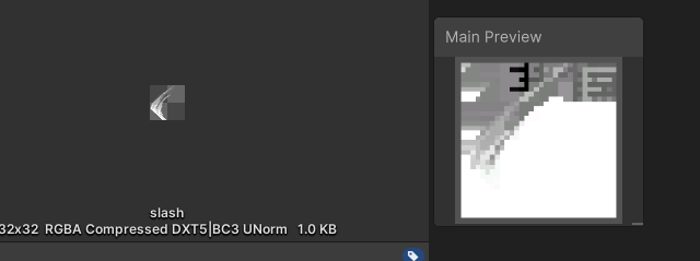
(i'm using a sprite unlit graph with urp on v2021.3.0f1)
yeah it appears the same
just some odd thing with the scene then yeah
@graceful cypress did you figure it out? 🙂
Anyone free to take a quick look at this? 🙂
scaling; I made my thing bloody huge, so making it a lot smaller fixed it pretty much.
thanks for all that helped though, i appreciate it. hope your problem gets solved @gusty horizon , looking at it that is way out of my knowledge hahah
If the texture alpha is always 1 or 0, you could lerp things together and it'd act like a branch
oh my god
you are a genius
why does it take less time for a compute shader to read from a texture2d than it does for it to read from a rendertexture
so this was harder than it seemed. Currently how I'm actually getting the outline:
// Where the texture is visible, returns the texture. Otherwise, where the UpperMask/LowerMask is visible, return the upperTint/LowerTint color
if (sample.a > 0) return sample;
if (sample2.a > 0) return upperTint;
if (sample3.a > 0) return lowerTint;
The problem is lerping still doesn't determine (and subsequently exit early) whether or not I'm dealing with a transparent pixel before returning any of the tint colors. Because I can't return early, the samples end up manipulating the colour where the texture exists (which I don't want it to, I want it to do nothing if the texture exists)
Similar issue with the other outline exercise I'm working on, except repeated 4 ways:
half4 sample = SAMPLE_TEXTURE2D(_MainTex, sampler_MainTex, i.uv);
half4 leftSample = SAMPLE_TEXTURE2D(_MainTex, sampler_MainTex, i.uvLeft);
half4 rightSample = SAMPLE_TEXTURE2D(_MainTex, sampler_MainTex, i.uvRight);
half4 upSample = SAMPLE_TEXTURE2D(_MainTex, sampler_MainTex, i.uvUp);
half4 downSample = SAMPLE_TEXTURE2D(_MainTex, sampler_MainTex, i.uvDown);

if (sample.a > 0) return sample;
if (any(half4(leftSample.a, rightSample.a, upSample.a, downSample.a))) return _OutlineColor;
return sample;
can you not do lerp(tint, texture, alpha)?
yeah, I tried return lerp(_OutlineColor, sample, sample.a); - but the output expectedly turns all transparent pixels to the outline color:

since the texture is pixellated (so you don't need to deal with unwanted colors seeping in) you could paint e.g. red where you want the outline to be, and black everywhere else, and then lerp again using that input
paint as in, the actual sprite?
the texture
ay yeah, we're on the same page, just wrong terminology. that would work, but i'd ideally want a solution a little more flexible than that - incase I want to swap between shaders in realtime
baring in mind this is not for any project, just trying to get my head around shaders 🥲
you could sample the texture four times, each offset by one pixel, and then saturate the sum of the alphas which should be 1 where there should be outline and zero otherwise
whenever i watch vids and view the code for other people's work, they have such an intricate understanding of the maths that powers shaders & can pull off awesome effects with very minimal branching. my maths is pretty damn limited I'm still having to google what a sin wave is. wish i paid more attention in school aha
i got as far as sampling the texture offset four times. but after half4 outlineAlpha = saturate(leftSample.a + rightSample.a + upSample.a + downSample.a), i still don't know whether or not i should be returning one of 3 things:
- the sample texture where it isn't transparent,
- the outline color where outlineAlpha != 0,
- transparent where both the above aren't met
there must be some magical way to do this without branching haha
use outlineAlpha to lerp between transparent and outlineColor and then use the texture alpha to lerp between that and the texture color
oh my god
that's it
AHH

(ignore the funky pixels, its changing with time)
thank you so much @karmic hatch
you're welcome :)
starting to realise more and more shaders is defo one of those "just write shit and figure it out" kind of things
Hey. Is anyone familiar on how to pass a single int32 into an unlit shader's vertex input (i.e.):
struct appdata_custom {
  int data : ???; // Which semantic should I use? POSITION?
}

v2f vert (appdata_custom v) { ... }
Currently data is the compressed position, normal, uv for a voxel. I was hoping I can cut down on the memory footprint by reconstructing the position, normal, uv on the GPU from data. Any ideas or thoughts are welcome.
any semantic you add will be automatically fed in to the vertex shader by unity. The only real way I can think of to achieve something like this would be to have an Integer property that you set elsewhere, and use that in the vertex shader. Out of curiousity, how have you compressed this data per-vertex? I'd be interested to know.
PS: I'm very new to shaders so there is almost certainly a better way, I just don't know it
also, I'm curious as to how much more memory efficient this would be once you've had a chance to perf test it
As far as I know, the semantics are always a specific type. BLENDINDICES is the only one that is a uint, all the other ones are float. However, you should be able to reinterpret cast the bits of an integer into one of the float attributes and then use asuint in the shader to reinterpret the bits as an integer again.
any semantic you add will be automatically fed in to the vertex shader by unity.
Should the semantic match the data type? At least thats what I got from https://learn.microsoft.com/en-us/windows/win32/direct3dhlsl/dx-graphics-hlsl-semantics, so in my case I think BLENDINDICES0 since its the only int type.
Out of curiousity, how have you compressed this data per-vertex? I'd be interested to know.
The compression is common with axis-aligned voxel engines, I believe, where each voxel contains its position in its chunk, normal index, color index:
Position is usually [0, ..., 15] for each of the x/y/z components => needs 4 bits for each (12 bits total)
Normals for axis-aligned cubes are limited to 6 (up/down/left/right/front/back), so you only need 3 bits to store the normal index, and do a lookup on the gpu float3 normal = NORMAL_LOOKUP[normalIndex]
Similarly, color uses a 256 array lookup to figure out the voxel's color.
All in all, its 12 bits (position) + 3 bits (normal index) + 8 bits (color index) = 23 bits, with room for future expansion.
Idk if this is any good, but I thought I'd give it a try.
Awesome. I thought so too. Would it be detrimental if the appdata_custom had just BLENDINDICES0 without any other semantics? I'm not sure what the semantics do in the background
I don't think that would be an issue.
As far as I know the semantics are
Hello friends! Hopefully this is the right channel for this question.
I'm upgrading a webgl project from Unity 2020.3.38f1 to Unity 2022.2.1f1...
I'm getting the following error in 2022.2.1f1 (works fine in 2020.3.38f1).
I'm having a number of issues related to shaders (BIRP, Post Processing Package v3.2.2 <- have a different issue with this posted in that channel, not sure if related to these issues or not). Trying not to cross post but the post processing issue is here: #💥┃post-processing message
Not sure what I'm really looking for so any advice would be appreciated... not sure if there is a setting I'm missing? If there is more info I should provide, please let me know.
First issue is with the Standard shader oddly enough... you can see it is now grey (?!) but should be white.


Next is a combination of the Autodesk Interactive shader (which I believe is also built in: https://docs.unity3d.com/Manual/Shader-Autodesk-Interactive.html) and a standard shader.
I'll post one more example but I have a bunch...


Last sample is the standard shader and the knife hologram shader from the asset store: https://assetstore.unity.com/packages/vfx/shaders/sci-fi-hologram-shader-170106#description


Guys how can I practice adding shaders to existing assets? These shaders would alter the look of the asset and adding details on existing materials
Does anyone have any good guides that show this instead of adding shaders to shapes?
hello everyone, I recently implemented a fractal dust from shadertoy, but its creating artefacts like below:

any idea/suggestions what causes such geometrical pieces/artefacts?
Could it be a reflection/specular feature?
its an unlit shader so no reflections. But it uses wavelet noise from : https://www.shadertoy.com/view/wsBfzK
Apparently, when I bump up the tiling these artefacts show up

I'm having some troubles using the Scene Depth node in Graph Editor with Isometric view. There was a bug report a while back and it was marked as resolved, but maybe it's a problem with my graph.
It works and looks fine in Perspective, but the second I switch to Isometric it just flat out disappears


It sorta kinda does something when I change the Offset to a higher negative number (in this case -16)

Running URP with Depth and Opaque texture enabled in the Pipeline Asset
Anyone have an idea what controls the inclusion of these two textures (OpenGLCore) in my shader? They are used for rendering glossy reflections blended from two reflection probes. Oddly, UnityShaderVariables.cginc seems to always include them (no preprocessors/keyword), but nonetheless in my list of shader variants, there are variants that do and do not include them.

The only thing that seems to control anything is a setting in Graphics Tiers, but that only controls whether reflection probe *blending * is performed. But oddly, the declaration of those two textures is independent from whether they're actually both needed. (I.e., unity_SpecCube1 is still included, just not used.)
Texture samplers for lightmaps similarly seem to be "magically" included or not included in separate variants, without me seeing any logic what actually controls that.
I'm trying to understand, what even is the .w/4th float in the Screen Position? From my mild messing around i can see that xy is literally which pixel on the screen it appears on, z seems to be the depth, but W only seems to appear when I'm close/inside the object
Hey guys I need help, Im creating a tree and I want that my leaf texture use a second color as a variation (some leaves should have color 1 and some color 2). Is there a way to random mix between 2 color nodes?

Perhaps a Blend node with a Random Range node?
Or a Lerp node
(could also use simple/gradient noise as the input)
Oh wait they want two use either one, not a mix
Are your leaves separate objects?
No my leaves are 1 object. Just 1 texture duplicated on each UV quad
The isometric view uses an orthographic projection, where depth works differently. (I've got a full post about depth here : https://www.cyanilux.com/tutorials/depth/)
If this is only an editor issue and you don't need orthographic views in-game it's easiest to just ignore this.
If your game uses orthographic only you can switch out the Subract node inputs. The image below shows the orthographic counterparts.
If you need to support both projections you can use your current inputs and the ones below with a couple Branch nodes, using a Comparison & the Orthographic output from the Camera node (returns 1 if ortho, 0 otherwise).

My game works in Orthographic, tysm I'll try it out in just a second <3
@regal stag works like a charm!! will absolutely have to go through that post as well, massive thanks

Hello! Does anyone have an idea why my portal is able to display our camera when it's target platform is windows but not android?


how do i get a pixel from a texture2d in a compute shader? im trying to make a terrain generation shader and im not really sure how to get data from the heightmap.
sshow your render texture inspector
example:
https://stackoverflow.com/questions/72375421/reading-data-from-rwtexture2d-in-compute-shader-unity

Stack Overflow
I'm learning compute shader with Unity, but I've encountered a bug when transferring RenderTexture to the compute shader. Basically, there're 2 texture being transferred, renderTexture and copyTex....
I don't seem to have one, but there is a script for setting the settings i think. I use this tutorial https://github.com/SebLague/Portals/tree/master

it's created in code looks like
based on his video
Yes, i think the script is called portal.shader
I found this:
https://forum.unity.com/threads/render-texture-showing-black-square-on-android.1248307/#post-8452478
Since your RT is creted in code you'll have to SET this format in code, which you can do with:
https://docs.unity3d.com/ScriptReference/RenderTexture-depthStencilFormat.html
Thank you i will try
what should i be using to make a skybox shader?

As always Ben Golus has pretty much explained it all in a forum thread https://forum.unity.com/threads/what-is-screenpos-w.616003/
Unity Forum
I'm a noobie at shader programming and am trying to learn to create intersect highlight effect. but I can't understand some of the concepts and...
can anyone explain this

voronoi refuses to be rounded but if i pass it through another node first it works
Can't we pass struct array data to shader?
I have to implement something like it?
ublic class VoxelTextureController : MonoBehaviour
{
    [SerializeField] private Material _voxelMaterial;
    [SerializeField] private TextureDefinitionCollection _textureDefinitionCollection;
    private static readonly int TextureDataID = Shader.PropertyToID("TextureData");

    private void Start()
    {
        var textureDefinitions = _textureDefinitionCollection.Textures;
        var textures= textureDefinitions
            .Select(t => new Vector4(t.UVCoordinateIndex.x, t.UVCoordinateIndex.y, t.Resolution))
            .ToArray();

        _voxelMaterial.SetVectorArray(TextureDataID, textures);
    }
}
or use compute shader?
I would like to pass texture data array to shader
You can with ComputeBuffer. It can also be used with regular shaders, but isn't supported by all platforms such as WebGL.
I do not want WebGL, thanks
My way is OK? instead of sending duplicated data for each vertex, I send that data array once and read it in the shader based on array index.
Vertices only send that index
  var textures = textureDefinitions
            .Select(t => new TextureData { UVCoordinateIndex = t.UVCoordinateIndex, Resolution = t.Resolution })
            .ToArray();

        var size = System.Runtime.InteropServices.Marshal.SizeOf(typeof(TextureData));
        var buffer = new ComputeBuffer(256, size, ComputeBufferType.Default);
        buffer.SetData(textures);
        _voxelMaterial.SetBuffer(TextureDataID, buffer);
Possibly a bug. I've also had strange behaviour with the Voronoi node in the past (specifically when using Posterize node - in previews it would look fine but not in scene/game). I think it may be caused due to the loops used in the generated code but not exactly sure why.
Thanks again, changing the depth to 16 worked :)( viewTexture = new RenderTexture (Screen.width, Screen.height, 16);)

Can I compress texture 2d array? I have created a texture 2d array by script. It says, does not support compression format.
Any better way to create a texture 2d array (compressed) and use it in a shader?
File size is 56 MB for only two textures 2048,2048
"Also, this class does not support Texture2DArray creation with a Crunch compression TextureFormat."
that sounds to me like other compression formats should work
https://docs.unity3d.com/ScriptReference/Texture2DArray.html
how are you putting the data into the texture array?
what format are the textures before you put them there?
Hi, is there anyway to change to UV of only part of a texture? I'm trying to make an effect that will only affect the pixels inside a mask
you could use the mask texture to decide / influce the change of the UVs for the other texture
@knotty juniper that sounds like what I need, can you explain how I would go around doing that?
I have the mask as a color that I create in the shader and not as a texture
use one channel of that color in a lerp to blend between the non offset / modifyed UV's and the modifyed UV's for the main texture
@fervent garnet

@knotty juniper I like that idea, thanks i'l give a try
@knotty juniper for some reason I cant connect a Color mask (vector1) to a the time port of the lerp? I tried to make it into a float4 instead but it wont connect, any idea?
can you connect it if the lerp is connected to noting elese?
Thanks @knotty juniper your question helped me figure it out ^^, it works, thanks for teaching me something new 🙂
   Texture2D sample = textures[0];
            Texture2DArray textureArray = new Texture2DArray(sample.width, sample.height, textures.Count, sample.format, false);
            textureArray.filterMode = FilterMode.Trilinear;
            textureArray.wrapMode = TextureWrapMode.Repeat;

            for (int i = 0; i < textures.Count; i++)
            {
                Texture2D tex = textures[i];
                textureArray.SetPixels(tex.GetPixels(0), i, 0);
            }
            textureArray.Apply();

            string uri = path + filename+".asset";
            AssetDatabase.CreateAsset(textureArray, uri);
RGB24 is OK
what happens if you compress the texture before
you use
https://docs.unity3d.com/ScriptReference/Graphics.CopyTexture.html
to copy them over the the array?
RGB24 takes 16 MB with respect to 2.7MB
OK, I test it, thanks
(not tested on my end ^^)
How should I use?
textureArray.SetPixels(tex.GetPixels(0), i, 0);
The only api to set pixels in tex2d array is SetPixels. I cannot find SetTexture
hello there, how do I make a new shader in a way it uses the spritedefault shader as a "base"? i have the problem that my shader is not lit.
the second parameter is which texture in the array to set pixels for
or does somebody have good resource to learn this stuff
So? They suggested I use Graphics.CopyTexture
How can I assign that texture to texture 2d array?
Hey, would anyone mind explaining some stuff about custom render textures to me? As far as I can tell, trying to update it via code will "overwrite" the last update. Is it possible to preserve consecutive update results?
f.ex, if I have an update zone in one corner of the CRT to turn it blue, update, then do the same in another corner to turn that corner red, the blue corner will revert to the original texture.
I don't see how it would "revert" as there's no original data stored anywhere to revert to
maybe share the code you're using?
i actually figured out the issue, it was because i was calling the CRT.Update() in a for loop
i dropped it into a coroutine and it's working now, but it has a visible... "speed" if that makes sense
not 100% sure how to fix that?
    public void UpdateCRT() {
        atlas = atlasAsset.GetAtlas();
        StopAllCoroutines();
        StartCoroutine(ProgressList());
    }

    IEnumerator ProgressList() {
        for (int r = 0; r < targetRegions.Count; r++) {
            AtlasRegion region = atlas.FindRegion(targetRegions[r]);
            if (region != null) Debug.Log(region.name + ": " + region.x + " " + region.y + " " + region.width + " " + region.height);
            else Debug.Log("Null region.");

            CustomRenderTextureUpdateZone[] crtZones = new CustomRenderTextureUpdateZone[1];
            CustomRenderTextureUpdateZone crtZone = new CustomRenderTextureUpdateZone();
            crtZone.updateZoneCenter = new Vector3(region.x + region.width / 2, region.y + region.height / 2, 0);
            crtZone.updateZoneSize = new Vector3(region.width, region.height, 0);
            //crtZone.needSwap = true;
            crtZones[0] = crtZone;
            crt.SetUpdateZones(crtZones);
            crtMat.SetColor("_Red", targetColors[r]);
            crt.Update();
            yield return null;
        }
}```i took a video of the process in question
it's not slow persay but it's slower than it could be- if there was a callback for when update() finished f.ex it'd probably be nearly instant instead of one frame per slot
Can I pass custom struct data in input/output structs (vert/frag struct data)? or the only type if float2/float3/float4 and primitive types
float2 Something2:TEXCOORD2;
float3 Something3:TEXCOORD3;
I pass int index for each vertex to a shader using SetUVs. There is precision problem that results in texture distortion/ clutter
It was not resolved, even by adding round() to convert float to int : TEXCOORD.
The only way it works is when I define TEXCOORD float for input data but int for output data
   struct appdata
            {
                float4 vertex : POSITION;
                float3 normal : NORMAL;
                float4 uv : TEXCOORD0;
                float4 tileData : TEXCOORD1;
                fixed4 color : COLOR;
                UNITY_VERTEX_INPUT_INSTANCE_ID
            };

            struct v2f
            {
                float4 uv : TEXCOORD0;
                SHADOW_COORDS(1) // put shadows data into TEXCOORD1
                fixed3 diff : COLOR0;
                fixed3 ambient : COLOR1;
                fixed3 color : COLOR2;
                float4 pos : SV_POSITION;
                int4 tileData : TEXCOORD1;
                float3 worldPos : TEXCOORD2;
                half3 worldNormal : TEXCOORD3;
            };
ok so i found this, and i noticed that there is a noise function, so i tried it, and i got an error, im not sure why.
https://blog.actorsfit.com/a?ID=00750-aaa7d725-cc26-4272-9edc-079754b49a55
float random(float2 uv)
{
    return noise(uv.y);
}
fyi: returning any simple float works fine, so this line is likely the problem
even replacing uv.y with a simple float returns an error
so im assuming its the noise function
Hello there ! I'm working with HDRP shadergraph and I wanted to know if there was any way to blend the materials of the intersection between 2 objects ? Kinda like Virtual Textures on unreal
How to create this mask shader for progress, I want to create 3d filler for my game with gray empti color and texture fill color

but my shader not working


i want to fill from bottom to top
noise takes a vector as input
https://learn.microsoft.com/en-us/windows/win32/direct3dhlsl/dx-graphics-hlsl-noise
Generates a random value using the Perlin-noise algorithm.
While cg/hlsl does technically have an intrinsic noise function you should ignore it. It doesn't work in vert/frag shader targets (that includes surface shaders too). Write your own or find noise functions online instead.


I don't think you use Blend with surface shaders. You need to specify alpha in the #pragma surf .. line. See https://docs.unity3d.com/Manual/SL-SurfaceShaders.html#:~:text=Optional parameters-,Transparency,-and alpha testing
it is not rendering in my ui camera now


Is that background rendered by the same camera? Perhaps it's rendering behind it? Could check Frame Debugger. Maybe try adjusting the render queue (via "Queue" tag)
i just added alpha: blend and it stops rendering
and one more little question
it won't let me use half2 uv_MainTex_2 : TEXCOORD1;


Beginner question here: do normal maps have to be images, or is there a way to do it via Shaders (e.g using the Noise node to create a normal map)
You can kind of do it via shaders. Especially in Shader Graph, there's a node "Normals from Height" that generates a normal map from a height map. Depending on what you want to achieve, texture normals don't make much sense, like for example procedural water using scrolling noise layers.
However generating Normals for complex textures like, i dunno, circuits or something, is easier to do with textures than through calculation I think.
^
fundamentally it would just be derivatives of some height function, and for some types of noise you can calculate analytic derivatives at every point
Exactly!
Okay great thanks. I was worried that importing so many images/maps might be resource-heavy for the user and that using Shaders might be a lightweight way of doing it. Would that be right?
It depends. Yes, it is resource heavy, but especially for good normals, the artistic freedom of using importet textures can be more powerful.
It's also not a lightweight way of doing it.
Sure, it takes up less storage and memory, but calculating the derivatives is more taxing on the gpu than loading and sampling the textures.
Both options have their use cases. What would be yours?
why do I not have a transparent option in my shader? every tutorial there is has one by default and i can find anything online about it.

.

you need to open Graph Inspector>Graph Settings -> There you have the Surface Type Dropdown.
Ahhhh thank you, that makes sence!
Hi all, I also basically joined due to a question:
Does anyone have an Idea on how to get a Shader Graph Material to be used as the Update Material to a Custom Render Texture?
When I configure it like this, it just won't update. No matter whether I do an OnDemand Update or Realtime...
It just won't update with a Shadergraph Material.

I’m just fooling around with the tooling right now so I can become more accustomed to it, so I don’t really have a use case right now. That was all interesting to learn though, thank you!
Sampling a normal from a texture is : 1 sample
Calculating the derivatives from a heighmap is at least 3
Calculating them from an arbitrary node is done using ddx/ddy (screen space derivatives), and can often result in blocky looking normals
With recent version, shadergraph has a custom render texture target that should be exactly what you need :

Oh nice, I had no idea that was added
Note that if you want your CRT to be an input of the shader (some sort of update loop for simulation ?), you'll need double buffered CRT, as it is not possible to read and write at the same time
Can tilemaps not act as shadow casters?
Nevermind, got it to work 👍
I'd like to create a simple atmpsphere for tiny walkable planets in my game (basically a foggy sphere) but it still has to look like for when your inside of the object with the shader so like its a volumetric. Is that possiple with shader graph? Or will I have to.... code?
Does anyone know if you can do this in HLSL?
(float) !mask.x
to get a 0 from a true boolean
How do I "offset" Time in a shadergraph?
example - Sine Time happens from 0 to 1, but how do I make two Sine times reach 0 and 1 at a different point in time?
adding to the value doesnt offset it, neither does multiplying or dividing
in an if statement, when sine is 1, I want it to be, say, 0.2, but still to oscillate 0 to 1 just at an offset time does that make sense?
I cant find the words to describe what I mean
You'd modify the time value in some way I assume. e.g. adding time would "start" the object in the future, if that makes sense
Since these are shaders though, they'd all execute the same code and it wouldn't really change anything
I assume you want each instance of an object to have a differently offset time
how could I recreate the look of a crt display? i am looking to use a movie texture to play a video on an in-game crt and i wan the screen to have the crt look

How do I offset Sine to be more like Cosine, but just not EXACTLY an offset of exactly 0.5 like cosine is to sine
I still want peaks and valleys of 0 to 1, I just want sines to not all hit 1 at the same time
Since Sine Time is just Sine(Time), you could add a value to time, like I mentioned. If you want each object to have a different time value, the offset would need to be unique. You'd have to pass each instance using the material a unique value. The easiest would probably be a MaterialPropertyBlock, but those can have issues with batching
I dont know what you mean by object or materialpropertyblock, this is not per object
This is one single shader
Yes, and I assume you have many objects that use this shader, correct?
And you want each object to have a unique time offset
Im asking what math do i do to grab one of those sines and slide it left and right, not scale up and down, not translate up and down

You add to time.
Do you think water mesh (material) has been separated from others? or all have shared material and inside the shader it handles which tile is water and should be animated


OH you meant take the sine of time
and not sine time
Okay now that's clear, I understand what you meant now. Thank you 👍
alright
Hello, could someone help me? I am trying to make a toon shader through following several tutorials, but I have come across the problem that I can't get shadows cast on my object

here is my function

I tried connecting it directly and some other variations, but no matter what I do shadows aren't cast onto it
here is the code

I'd guess an issue with keywords. Try using the Main Light & Main Light Shadows subgraph from here instead : https://github.com/Cyanilux/URP_ShaderGraphCustomLighting
I have tried doing so, but nothing has changed
so im fairly new to writing shaders, and i was wondering two things, firstly, how can i make a low-res pixel art style, and secondly, how can i apply a hard black outline in a cartoonish style to the low-res look
my best guess for #1 would be taking every pixel and applying its color to the next pixel over, then skipping the pixel that the color was applied to, and repeating, but im not sure that shaders work in that sort of iterative fashion, because from what i gather all code written in a shader is applied to each pixel indevidually
hey, how do I make an object transparent on one side but not transparent on the other with a smooth transition using unity shader graph? The image is an example of what i want in blender if the object with the shader was a sphere

You can plug e.g. the X component of an object's position into a smoothstep and then use that for the alpha
ill try that thanks
Hi guys! I need to make flat transparency effect for my UI elements, which doesn't stack on top like the circles on the left. Is that possible? And if it is how can I implement it?

And this is the in-game UI concept

for cg coding, is there a built in way to convert rgb to hsv and vice versa, or do I need to create my own script for that?
nvm, I found a script that someone else already made for it
I'm not sure if you can access the opaque texture for UI stuff, but if you can, then that could be useful. (Though if you have any transparent elements in your scene, they'd overwrite those too)
Could also look into using a UI mask, or a texture that's the right shape if it's a permanent feature
how could I recreate the look of a crt display? i am looking to use a movie texture to play a video on an in-game crt and i wan the screen to have the crt look
something like this?
https://www.youtube.com/watch?v=jcNJbR85gK0
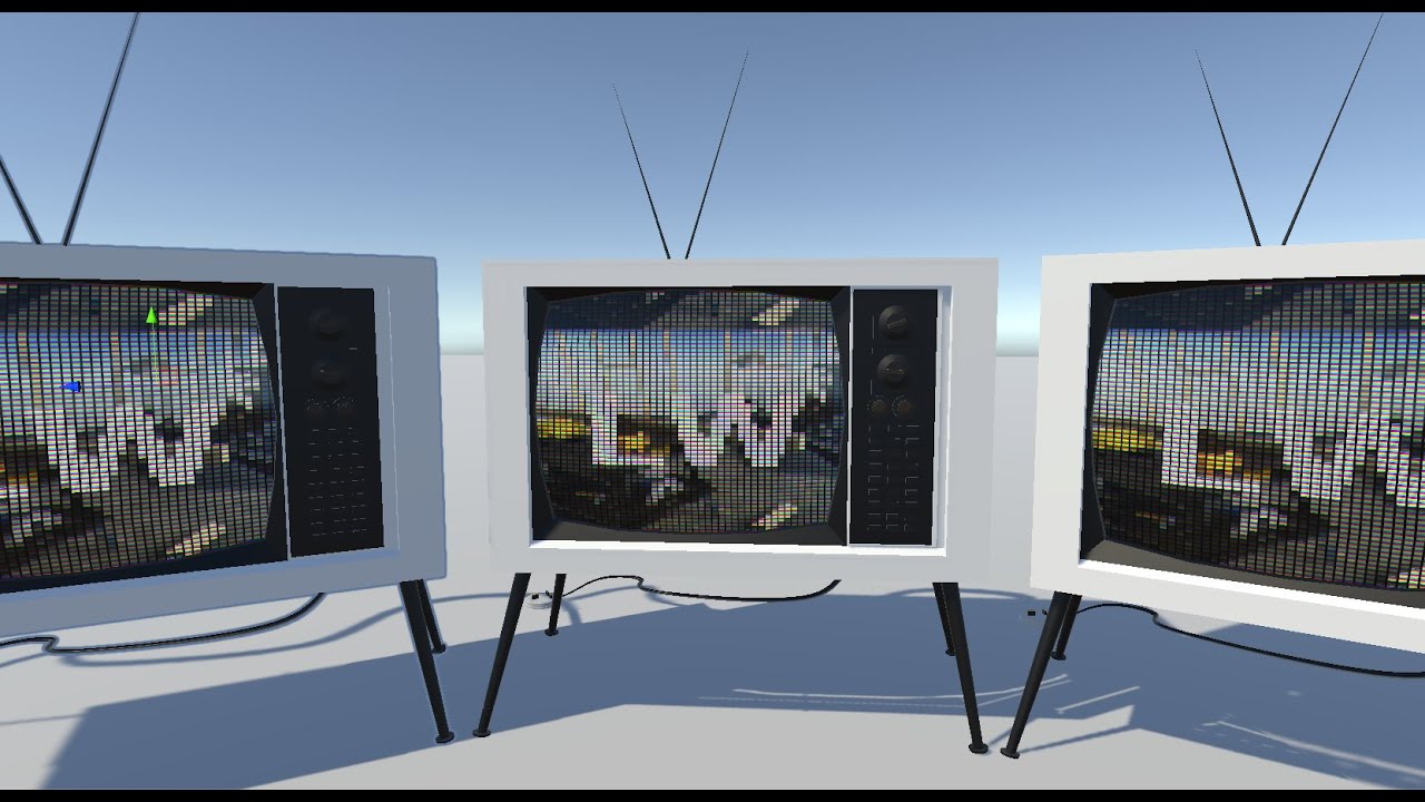
This Shader is available in Asset Store: https://bit.ly/lwrp-materials-3
This is a quick tutorial on creating an old TV effect using shader graph in Unity 3D LWRP/URP
Checkout my assets for more Tuts!
Popular Links
URP Mater...
thanks
Anyone have a clue as to why a toon shader is causing shadows to have an antialiased/transparent edges effect, and why point lights would be amplified within shadows?

Followed this https://www.youtube.com/watch?v=RC91uxRTId8 for the shader.
✔️ Works in 2020.1 ➕ 2020.2 ➕ 2020.3 🩹 For 2020.2 and .3:
► When you create a shader graph, set the material setting to "Unlit"
► The gear menu on Custom Function nodes is now in the graph inspector
► Editing properties must be done in the graph inspector instead of the blackboard
► In Lighting.hlsl, change the line "if SHADERGRAPH_PREVIEW" to "...
it may have to do with the amount of lights you have in your scene
i think theres a setting to adjust it
Anyone know why the outline seems to be disconnected? Using unity toon shader on URP

This is another model using the same material

lmao nvm it was shadesmooth
Firstly, you should know how the outline shader works. Then you will know the answer.

I'm planning to change my hologram shader to show the bottom half of the mesh as solid.
But, the % solid may vary per object, could I pass that extra data to the shader?
I guess a lame way would be to give each object their own custom instance of the material with a different parameter, but I'm using a render feature to replace their normal materials so I would very much prefer sticking to one material
Material property block could be a solution
I am looking to create an effect where I can materialize objects. Specifically, show part of the mesh with the normal "solid" materials and the other part of the mesh with my hologram shader. I also need a way to control what % of the mesh belongs to which shader. And each mesh may have their own %.
Any ideas welcome
So far I've been able to get the shaders to stack properly using render features in the URP asset
Sounds perfect, but "breaks dynamic batching"
How bad is that?
do you use dynamic batching?
It would also break the SRP Batching that URP uses. Whether that's a problem really depends on how many objects are being drawn like this
anyone know how I can make a shader like this?

Can look up toon/cel shading tutorials to get the colour-banding like that.
For the pixellation could render using a camera with target set to a Render Texture at a smaller resolution than the screen. Then find a way to draw that texture to the main camera. (e.g. Quad mesh, Raw Image UI, Blit to screen)
Any ideas?
Well, there's "other" ways. The idea(s) mention by @dim yoke and @regal stag are more traditional, if you don't want to use separate materials, which would be the easiest.
But if you don't want to use MPB's, you could use different meshes for each object (dynamically create the mesh instance for each one) and THEN you could stuff an instance index/ID of some sort into one of the mesh attributes, say vert color or one of the UV channels. If I went this route, I'd copy the mesh data from some template mesh into a cached list of dynamic meshes, and mark the cache entry as in-use or available. Then I'd romp through the mesh and update things.
Your shader could then have some kind of array/buffer passed for each object. And each object's entry would contain the % materialized/full.
That's all a bit hacky and a lot of work for what would otherwise be separate material instances. The main problem is that you/we don't have a user-definable mesh-instance attribute that unity passes directly....one for each mesh. Say a float. So you have to set this dang value on all verts of the mesh.
If anyone knows of a better way to link a mesh instance to a structured buffer via user-managed C# code, I'd like to know about it. I mean, unity does it when it does MPBs and GPU instancing. But we don't have an attribute we can use for our own data mapping a mesh to a c-buffer or other UAV.
heey i just started working with a sonar shader but it effects the whole mesh(terrain) and its repetetive, it uses a sin wave, but i want to make it that the sonar effect waves appear on button press in a radius, 3 button presses 3 waves after eachother, how can i achieve this? or this is even possible?
any idea why the projector is creating such a huge effect?

I dunno if there are any raytracing pros here but. I'm doing DDA raytracing (https://www.shadertoy.com/view/4dX3zl) and it works just fine, but I'm trying to skip empty space by implementing brickmaps (8x8x8 voxel volume), and to me the logic is perfectly sound, but does this math not make sense??
I increment the lowest value sideDist by adding the deltaDist (ray distance needed to increment axis index) to it. This works fine, but once I start trying to approximate this while skipping space with a brick it breaks.
Basically we can check every step which direction we need to go using the DDA, so I keep track of when I enter a new brick, and when I do I increment a separate brickSideDist to keep it in sync. Once we enter a space we need to skip I increment the brickSideDist first of all, then I get the brickIndex by taking our voxelIndex and dividing it by 8, then I add 1 to it in the axis we traversed, then I multiply it up again by 8 and add the voxelIndex with modulo 8 so we have the right index when we're casting a negative ray.
Then I subtract the old index from the new index to get a distance, then I multiply it by our deltaDist to get a total distance travelled along the ray in that axis. After that I divide our calculated distance by all three of our deltaDist axes, floor them, and that should tell me how many steps of each were traversed. Then I simply add this multiplied by the deltaDist to the sideDist, and the same to the voxelIndex multiplied by sign(rayDir).
Maybe i'm using too many variable names here but am I missing something here? It all checks out to me but I can't get this logic to work in practice. The rays seem to bend all over the place.
https://pastebin.com/bi16gVfU that's the code, at line 183
I'm trying to use shader graph to create some post-processing effects, I've created a custom render texture, set a camera to render to that texture, created a canvas with a RawImage, which I've applied the texture to, then set the material for the texture to my shadergraph material. However it doesn't appear that anything I do in shadergraph has any effect


so apparently i should use a render texture to lower resolution, but i dont know how to use them in combination with my already made shader
What shaders?
i think im figuring it out
ok well i got a vert frag shader and im struggling to find how to lower resolution to create a pixelated effect from the current visuals i have
i think i managed to get the render texture sort of working kinda
i assigned it to the camera, then made a rawimage element and put it in there
and it displays visuals, just not properly, ill record a gif
hold on..
ok i fixed the issue
How did you fix it? I either get output but no shader effects, or just a solid colour

well i made a material
assigned the render texture to it
assigned that material to a ui element
made the material an unlit texture material so you dont get lighting interferance
then i made sure the render texture was in the correct aspect ratio
and that it was assigned to the main camera
thats about it
If I put some screenshots on here can you see if I've gone wrong somewhere? Right now I've just set the shader to output a solid colour
Here is my material:

oh i dont know much about the shader graph
i just wrote my own shader, you are sorta on your own there
but i do have a new issue..
how can i get the render texture to maintain a consistant look of an object whilst still bieng pixelated
let me set up an example..

To define const verctors, we should define static const?
#define works only for single primitive types like float?
static const float4 vec = float4(0.0,0.0,0.0,0.0)
#define PI 3.1415
#define can be whatever you want it to be, it will just replace all instances of the macro with whatever you define it as, so you can do:
#define VEC float4(0.0, 0.0, 0.0, 0.0)
So typing VEC is the same as typing float4(0.0, 0.0, 0.0, 0.0)
Any ideas
noise nodes in unity shadergraph arent quite sharp, any workaround for the same?
simple gradient shader

if the object position goes from -1 to 1 always, then the full gradient should be applied to every object no matter their size or geometry

instead, some objects are able to reach higher parts of the gradient somehow.
any hints appreciated
check the pivot in object/local space in the editor? maybt its a bit off?
thing is the bottom is also slightly different.

its as if the capsule is longer geometrically
simple gradient shader
Does anyone know of anywhere to get Unity Technologies depreciated assets?
I'm looking for the Blacksmith Environment asset - https://www.assetstore.unity3d.com/en/#!/content/39948 - or is there anyone who has it in their assets who would be willing to upload it somewhere for me?
Is there a way to disable Unity shader compiler optimizations, so unused variables are not scraped out from the shader output ?
is there a way to export this shader node to unity? I was trying to make a clawhost-like weapon, but its a "plungershot". Thing is i didnt found any rope texture that fit, so i hand made one, is there a way to export it to unity?

Cubes go from -0.5 to 0.5 iirc
(spheres too)
Also iirc the preview objects in shader graph might be slightly different from their unity primitive counterparts, e.g. the preview sphere is a UV sphere while the Unity primitive is a cube-sphere and the preview one might go from -1 to 1 in object/world space too
Hello, is it possible to create a texture like this in a shader procedurally? I guess the grid is easy but is there math that pinches it like this?

Sure, if you have a shader that can draw these lines straight, it should be trivial to add the pinching.
If you can control the width of the area the lines are in, you can change it based on the Y position.
I guess it's clear how to split the color channels of the UVs but how do you access the Y position. Something to do with vector2?
Wait, is there a VectorToRadialValue alternative in Unity? Or should it be built from scratch
please tell me how to invert the value of fill amunt so that the filling remains the same (transparent from below, filled from above), but the value on the progress bar was not 0.8 but 0.2

Without changing the values you put in this will not work
you can change the Fill Origin to Bottom
but you would need to do
1 - oldfillvalue
to get the new correct one
Hello. My shader has in input a float3 variable named _PositionToDraw, which is a position in world space coordinates and I would like to color the matching and closest pixel.
I saw that i.worldPos and _PositionToDraw has both correct values. How can I calculate if the pixel is to be colored or not? Thank you!

It would be easier to color all pixels that are within a certain distance from the position. Is that fine, or does it have to be just one pixel?
It's not trivial to figure out which pixel is closest. That requires comparing all the pixels with each other to see which is closest.
Unless the shape you're working with is something that's simple to define in math, like a sphere or capsule.
Actually I'd like to be all closest pixels. How can I compare the distance? Distance like I used won't work

How can I achieve a similar effect to these glitch artifacts in shadergraph?
In my shader currently I have a main texture, and the glitch texture which is used for the artifacts
I don't know how to overlay the artifact texture in this blocky like formation
I guess, first split your screen to grids, add vertical noise, compare it with threshold and get the mask, Sample a predefined glitch texture or the generated one based on that mask
Is it possible to only pixelize the rendered object using a shader? (i.e. not a post-processing effect)
Is there a way to make Color be a color swatch and not a vector4?


is there a less dumb way to get a binary white/black to fill a progress bar with

use the Step node
Ah yes thanks, that's way more efficient 👍
is there an easy way to convert this into a Sawtooth wave?

I googled it and the net said to use modulo on the sine to make it sawtooth
but that did not make the gradient sawtoothed
I want the gradient falloff to be in a single direction, not both
There used to be one single node that would just loop anything plugged into it
but now I can't seem to find that
I google things like loop, repeat, but no results
Fraction, that was it
Hello all - I'm looking for a way to setup a shader in Unity with the following parameters:
The shader is supposed to utilise the R G and B values of a texture map, in order to change any corresponding element to whatever color necessary. For example, the torso armor would be red and would be effected by any red part of the mask map. The legs armor would be in blue. The trim of the armor in green, etc. Then a color could be picked for anything corresponding to said R G and B values...
are there any resources showing how to set up a shader like this? thanks!
You can make a shader that seperates a texture into the three channels, and then with booleans you can have the shader choose from the three
I'll set up a quick example in shader graph
Is this what you're looking for?
This chooses between the rgb channels using branch nodes and a float (channel)

Isn't there light dir in shader graph ?! (unity 2021)
horizontal gradient + smooth step

I think there's one in 2022.1+ now but otherwise can use a custom function node. I've got some here (with subgraphs) : https://github.com/Cyanilux/URP_ShaderGraphCustomLighting
yes, I have added a custom node
but it is weird really, it is a basic node
Put a package in repo while it does not contain basic nodes
Should be able to sample the mask map, and multiply each channel by a color property, then add together. e.g. for Shader Graph would be similar to this : https://www.youtube.com/watch?v=4dAGUxvsD24

Post containing Shader Graph file and Code version https://www.patreon.com/posts/quick-game-art-39412122
My Github site with all tutorials
https://minionsart.github.io/tutorials/
Twitch: https://www.twitch.tv/minionsart
Twitter: https://www.twitter.com/minionsart
Patreon: https://www.patreon.com/minionsart
Clean Soul by Kevin MacLeod
Link: ...
For a quad oriented vertically, the y position is just the green component of the UVs
What you want to do is generate the lines as a function of (x-0.5) (maybe using a sine() or something; the 0.5 is so that it's centered), and then you can pinch it by replacing (x-0.5) with (x-0.5)/y
After removing Library and reimporting, again it does not work
Shader error in 'Shader Graphs/water': Couldn't open include file 'Packages/com.unity.render-pipelines.universal/Editor/ShaderGraph/Includes/ShaderPass.hlsl'. at /Library/PackageCache/com.cyanilux.shadergraph-customlighting@73ccdd474a/CustomLighting.hlsl(60)
is there a way to create a shader that applies a uniform size border directly to a mesh face? I have lot of rectangular platforms and I'd like to achieve something like what a hat in time does with these platforms. I'm also using probuilder meshes if that changes anything

not planning to do anything like the crystals here if that simplifies things
Somehow it detects these red things on my texture.
Attached the image used as well as the meta
Unity version: 2022.2.2f1
URP Version: 14.0.4
Shader Graph Version: 14.0.4
There should be no things there


That doesn't seem to a fancy shader; you can see that the outlines aren't the same width or anything so it seems to be either texturing or maybe vertex colors.
This probably implies something like triangles barycentric coordinates, that can either be computed in a geometry shader (so, not shadergraph), or pre-computed and stored, let say, in the vertex color of the mesh.
Or, use well defined UVs to trace those lines.
I think most likely they selected the faces in a modeling program and did an inset operation
If it needs to happen at runtime it might be worth looking into making a similar inset operation within Unity procedurally
Just some options before you decide to go with shaders
thats probably not what they were looking for
sample the mask, split the color/vector into it's RGB components, then sum the R G B values, then you can get finalcolor = (R/(sumRGB)) * redChannelReplaceColor + (G/(sumRGB)) * greenChannelReplaceColor + (B/(sumRGB)) * blueChannelReplaceColor
this is ofc only one color mixing mode
it chooses the final color based on a weighted average
you can also just add them like
finalcolor = R*redChannelReplaceColor + G*greenChannelReplaceColor + B*blueChannelReplaceColor
this will increase the brightness of your final look tho where R G and B overlap
if you can choose because colors never overlap, I'd recommend the additive mixing, it's a cheaper effect, division is expensive
to optimize this, you can also do 1/sumRGB and then multiply with that
but the compiler might already do it for you idk
best to be sure

Older unity versions only support Shader Graph in the Scriptable Render Pipelines (URP/HDRP), but I'd assume VRchat requires the Built-in pipeline so you can't fix this.
Either switch to writing shaders via code, or look into alternative node editors such as Amplify Shader Editor or Shader Forge.
Hey, I need some help. Is there a "easy" way to add that my planes are always facing the camera?

In the tutorial I watch, guy has HDRP pipeline.
And we both use almost the same version of Unity.
But I don’t. have hdrp shader option for some reason

Sign up via my link will get two FREE months of Skillshare Premium https://skl.sh/romanpapush
—————
#Update: Blender 2.8 is out! https://www.blender.org/
—————
Heyo my dudes!
I really hope you will enjoy this advanced tutorial for complete beginners!
By the end of this video you will master the Air-Bending techniques of the ancients and will le...
The tutorial I follow.

probably an easy fix and a dumb question but I cant see any of the properties options under "surface options" for my shader material. I'm trying to get the material to stretch to cover the entire surface or even just access the tiling, and also rotate it by 90*

You didn't expose the texture as property ?
Hi guys. I created a leaf foliage shader and would like to add a second leaf texture and color for more variation. Is this possible?

thank you for everyone who replied to my shader q - was off sick so didn't have a chance to respond
Yes.
Do the same as you do already for an other texture, and change from tex1 or tex2 based on some random value for variation, by using a lerp or branch node
Ey ey ey, I'm looking for a shader blend material for... details mesh (grass on a landscape). Does someone has ever heared about that ? Or have any idea to create a well blend between my landscape texture and my grass details one ? I've already tried to do it with an alpha but don't have a good result. Getting the ground color and doing a gradient from bottom isnt possible because I have 2 different textures (Green and brown). Thanks in advance :)

I ended up getting radial coordinates of the grid and offsetted it but I'll know that there's a way to just control the axes, nice
I'm making my own lit shader and everything is working fine but I'm having one issue. When I have the exact same properties and texture maps on my material, on my own shader it's more glossy than on the Unity lit shader. Does unity do something with the calculations of the smoothness value and the metallic map or something?

This is unity version
This is my version

Exactly the same properties and values but my 'smoothness' is much more visible
my smoothness is directly attached to the smoothness of the root node so I don't calculate anything
I have my shader set to the same values as the rest: metallic, opaque, front faces,...
So you're not reading the alpha channel of the Metallic texture and multiplying that with the Smoothness property?
Nope
I was just about to try this
That's what this means. Smoothness is read from Metallic Alpha, but multiplied by 0.5

Ohhh okay, thanks! Makes sense 🙂
perfect!

Thanks again
Is it possible to add an animated noise distortion to a cube map?
im using the built-in render pipeline and am trying to add a the option for a specular texture to my shader graph. enabling "allow material override" unlocks the specular output in shader graph, but there is no option to change it to a specular material like there is in urp

I want glow water effect like Terra Nil.
My try
I do not know why the color of the uploaded video has changed


Any suggestion to improve it? better noise textures, tune params, etc.?
imo, one improvement, adding a mask texture because now, glow effect has spread out everywhere on the water.
thank you for the input on my question!
i think this is the most viable option and i'll give it a shot, thanks
Hi everyone,
I am kind of new in writing shaders and I am trying to achieve a slider effect on my world-space objects. So, to achieve this, at the end of the shader I am checking whether the alpha value of a given reference texture is above the fillrate variable. If it is, consequently, setting the alpha value to zero.
As a result, I have achieved what I wanted as in attached gif, but I am not sure, whether this is the most performant and best way to do it.
Is there any other way to achieve similar behavior, without using if statements? Or is this a valid and proper approach to get this kind of slider effect? https://codeshare.io/yoybdq

if would be more efficient to use the step function than an if statement