#archived-shaders
1 messages · Page 25 of 1
I'm using it as a ring buffer, appending one element per frame. I don't want uninitialized values in there before the buffer is completely full.
I guess that works, but there is nothing built in?
is the clear just occasional or is it frequent?
A quick google search of DirectX API functions says no
just when I create it
a little bit of both, i want it to be small waves and transparent but also reflections and refraction
If its just when you create it I wouldn't sweat it, use CPU fill or compute fill, if it was every frame or so then it'd be a big deal.
I didn't know ComputeBuffers started with uninitialized values. I guess it might depend on the GPU driver, but I would think that kind of thing would be documented.
Knowing Unity and C# as a whole they rarely have anything uninitialized, if its a freshly created buffer you shouldn't have to do any clearing
I just noticed that it had some values in it sometimes when I initialized it, so I assumed it was uninitialized.
Most of the time it is clear tho
Sometimes it even had values from the previous allocation
how?
If ddy(normal) is greater than some threshold you can say that's an edge
(or rather ddy + ddx)
float normalEdgeIndicator(float2 uv, float depth, float3 normal,float normalBias) {

    depth = getDepth(uv,float2(0,0));
    normal = getNormal(uv,float2(0,0));
    float indicator = 0.0;
    // indicator += neighborNormalEdgeIndicator(uv,float2(0, -1), depth, normal, normalBias);
    // indicator += neighborNormalEdgeIndicator(uv,float2(0, 1), depth, normal, normalBias);
    // indicator += neighborNormalEdgeIndicator(uv,float2(-1, 0), depth, normal, normalBias);
    // indicator += neighborNormalEdgeIndicator(uv,float2(1, 0), depth, normal, normalBias);
    indicator += ddy(normal)+ddx(normal);
    return indicator;
}
Like this? I don't really know where I'm supposed to insert these changes (once again, I'm just trying to port code)
how would i go about making water like this? https://static.wikia.nocookie.net/backrooms/images/6/67/Level-37-1.gif/revision/latest?cb=20220329170327&format=original

I also can't find any examples of anyone ever using the derivative functions to create outline/edge detection effects.
I don't know if it's a problem with my code or a just an inherit difference in how Unity and three.js handle camera normal texutres
Well gl
Is there a way to downscale the camera's normal and depth buffer?
I've gotten my outline to work but it has the issue where lines disappear at certain camera angles due to my downsampling of the render texture to produce a pixel art effect
Essentially I'm drawing these lines at full resolution and downscaling it which loses a lot of the original detail and causes issues with pixels disappearing when the camera is at certain angles/positions
Some things I can see in that shader:
-Refraction
-Alpha value based on density (you can use the Soft Particles node in Shader graph for this)
-High smoothness
-Tint
-Reflections (doesn't depend on the shader, use screen space reflections or reflection probes for example)
any idea where i could get started making this? like a tutorial or something
I don't have any specific tutorials to refer to, start learning how to use Shader graph with some basic tutorials. Assuming you are on URP or HDRP?
im on URP yeah
Water is a pretty common subject for shader tutorials
You can start with this video from Unity:
https://www.youtube.com/watch?v=gRq-IdShxpU
So does ANYONE know how to solve my issue?
@prime shale are you back?
hmm?

for one your normal mode was wrong


also second
you sample normal maps...
but you dont unpack them
in adition to that also
you don't use the geometry normals
when you sample normal maps, normal maps are normally in tangent space
your using them here as if they are world space which they are not
when sampling normal map textures
you need to unpack them
then blend them
and then blend them with the geometry normals

@grand jolt
you get me?
also wrong as in the normal mode should not have been reoriented
yes checking and reading through what you said
wdym by that
how do you unpack a normal
and what does that result
there is an unpack node that you can use as you see in my screenshot
but also as for why you do it, normal maps are just basically vectors stored as colors. When its stored as an image the range of this vector is a 0..1, vectors are -1..1 so what unpack does is basically take the normal colors and scale them to a vector range basically
bit of a rough explanation, skipping some details but thats generally what happens
you take a normal map image which is 0..1 and unpack it so it expands into -1..1
but it doesn't end there
normal maps are tangent space
and typically with normal maps you blend them with the geometry normals

yep

its correct, but looks like something is up with your refraction
it's screenspace refraction
so that means it's limited to whatever's on the screen
im aware of that
but you are right, it samples the scene render target, i.e. what you see which is basically screen space, and you are basically distorting that render target according to the surface normal
what is happening there is indeed a screen space refraction
can you send your shader graph again?
ok
2nd image is the custom function


its indentical to mine, so hard to say whats gone wrong
hmm
send the shader graph
ok
asset that is
shader code is compiled down
still 127 kb in unity's eyes
huh your shader is actually correct, which leads me to believe your normal maps might be wrong

the ones that your using for the shader
so I have to download new ones
not saying that
alr
what do your normal maps look like
oh
the ones your using


o
if you are using normal map textures they need to be interperted as a normal map
the texture type is default
it needs to be a normal map

your normal strength is probably very high
has anyone made a 'clipping plane' shader? I know its super simple to make a shader that hides everything behind it, but I want one that hides everything in front of it (for a cutaway effect). the posts I've seen about it on the forums haven't worked out
The 'Normal Vector' node should be in tangent space
it doesn't have to be in this case
also send your normal map files here
and also a screenshot of your material setup
i.e.

They should all be in the same space if they are going to be blended together
I think the blend assumes they're in tangent space
you are right, but with how his shader is setup if its set to tangent space then artifacts are introduced
case a point


that looks perhaps like the normal map is just very small on the surface, and when it's further away it gets mipmapped?
no, the mipmaps when at a distance would in a sense lower the strength and appear to be more clear
im not familiar with shader graph, but from how the node is setup it looks like it does factor in the space in which a normal is in
what are the artefacts you're referring to then, i think i might be misunderstanding
It makes no sense to blend together two normals from different spaces
I agree it doesn't, but looks like shader graph seems to actually respect them?
again I don't use shader graph, I hand write my shaders so I have no clue whats going on internally with that node
No shadergraph doesn't care, it just sees float3 and float3 and says 'yep this input is valid'
It doesn't know what space they're in
well in that case then we can correct it
And when you plug it into the fragment node, unless you specify otherwise (i think there's an option in the graph inspector) you have to use tangent space
all im saying is that with how his nodes were setup, I was able to blend them and it didn't cause any issues, it didn't make sense of course but it works
but its corrected


results are still the same
but with his setup here his normal maps have something funky going on because I have the same shader graph he does
Might be luck since the top of a plane has (0,0,1) as its normal, which is 'straight out' in tangent space
its possible
oh handy
looks like the sampletexture2d node has a built in normal unpacker

aaah
should have been testing it on a sphere lmao rather than just a plane
What ended up being the problem?
so I set the normals to be all blending in the same tangent space
and then finally transforming it into world space
from there also for the reflection probe
I brought back a view direction vector which is in world space
which seems to solve the problem
and it goes here right?

ok
and it has to be in world space
right
@prime shale I set the normal strength to 0 and


well
I don't think that's how it's supposed to look like
yeah I'm just gonna download yours and see what I messed up
it looks weird
it used to look good
now it's just bad
agh
ykw I'll just focus on the planet generation thing I was making
uh
ping ne
I thougt I sent the corrected shaders?
you did
and it's fine but
this just looks bad

it looked good before
something is still wrong
is the water plane you have just a quad/plane mesh?
what about the normal maps that you are using
plane


that is 0.1
it isnt linked to anything
I linked it


wiw
thank you very much

btw is the untile strength supposed to always be low or is it becoming curvy something wrong with it
stronger than this creates weird effects
hm
but it should be at a low value just enough so it disrupts the pattern
ok
I would also introduce a scalar vector for that untile
since it looks like you have it scaling with all of the UVs, add its own multiplier for it for scale
still looks a little tiled from above

and looks more like frosted glass than water
but overall fine
because your just sampling 2 normal maps both at similar scales
typically with my water shaders I simply sample the same normal map but at 3 different scales and combine them
each controllabe by an artist of course but
1 at a very large scale, 1 at base scale, 1 at a small scale
combine them
I'm gonna see if that works
and then you could combine it also with that "untile" trick
and that should get you most of the way there
there can still be cases where the tiling can be apparent but you just have to tweak it until it doesn't seem as obvious just like in here
I'm STILL trying to get help with my outline effect. Issue is that lines disappear due to the outline effect being applied before the color texture is downsampled for the pixelated effect. I need it to apply AFTER the downsampling but I have no clue and no one has been able to give me a straight answer on how to go about doing that.
sorry I might be able to help you in a bit, been helping out another bloke on here
Main issue is that the pixelize render feature can only run after rendering opaques (trying to set it before will cause it to do nothing) and the screen space cavity can seemingly only work before rendering opaques
https://github.com/itsPeetah/unity-simple-URP-pixelation this is what I'm using for the pixelize render feature
GitHub
Custom renderer feature to pixelate the screen. Contribute to itsPeetah/unity-simple-URP-pixelation development by creating an account on GitHub.
How to make 2d lit shader graph that will work same as "Sprite-Lit-Default"?
still looks tiled but alr

also is this thing where when you look up it's blue but when you look down it's the color of whatever is below the water


not to mention it looks weird underwater

well because nothing is done forunderwater
what does your material properties look like @grand jolt

which node is it for just setting everything to the color you want?
add/multiply takes the current color into account and ReplaceColor only changes certain colors not everything
Would just be a Color node/property
how would i setup a simple volume mask such that my mesh would cut out the visuals of my water from my boat
im using shadergraph so not sure how to do it in SG
only thing i can find is from old built in stuff which i guess wont work for URP
Stencil buffer perhaps.🤔
damn they really made it that much more complex than the old ways ? 😦
What was the old way that you found? I don't think it's that different
this but im pretty sure with URP/HDRP writing a shader like that will not work
The shaderlab stuff should still work the same way imho. I'm not sure about the render queue though.
I think in urp you're supposed to use the "render features/objects" feature.
https://bdts.com.au/tips-and-resources/unity-create-windows-portals-using-stencils-with-the-universal-render-pipeline-urp.html
oh thanks ill take a read 🙂
Does anyone know what tehse textures are?

not when the image is so small i can't see them
Still trying to do this lmao
basically: I need to downsample all the camera textures (depth buffer, depth normal buffer, color, etc) before rendering so the outline effect is applied on the downscaled textures
currently it gets applied and then everything is downsampled which causes issues
kinda wild no one has been able to give any information on how do this in three different unity discords lmao
is skybox rendered last in unity? my mask seems to also mask out the skybox so i get black
These look like materials, not textures.
I think it's rendered first.🤔
You can confirm that with the frame debugger.
Perhaps because what you'retrying to do is so niche and rare to do for anyone. I, for example, never heard of "depth normal buffer" as well as "downsampling" in unity context, which makes me think I can't answer your question. If these are some things that you implemented in your project, might want to elaborate on them. Otherwise, if it is a feature in unity, maybe link the docs page, so that potential helpers are on the same page with you.
theres some weird thing going on even though it correctly masks - the quad seems "delayed" to update its position so you see it lagging behind and the skybox is black

theres another weird issue too, if i dont have the camera selected in editor then the mask creates a blurring effect - but if i select the camera then the mask doesn't blur
see here

its like smudging
its as if the camera doesn't clear flags unless i have the camera GO selected in editor 🤔
but the lack of skybox does make me think the skybox is rendered last 🤔 or at least after transparency which is odd
my mask queue is Geometry+1
Mb that’s what I meant
I'm not sure about the delayed part. It doesn't seem noticeable on the gif.
As for the second gif, what you call "blur" is simply the camera not clearing the color buffer, so it keeps the color from the previous frames. Every other pixel is fine, because a new color is rendered, but that space seems to have nothing rendered on it(presumably because you even mask out the skybox).
You would have more clues on what's going on from the frame debugger, as I mentioned earlier.
is that a package in package manager or built in ? never used it before
Okay, then, these are materials. As for what they're used for, you're the one who's supposed to know that better than us, since it's your materials in your project.
It's built in. I suggest googling on how to use it to get some idea.
okay - im surprised you can't see the lagging though in the first gif
its not coming from the gif compression either
oh i fixed it
i changed it from Geometry+1 to Geometry+600
🤔
smells like a bug though to me
I'm not sure of the details of your implementation, but there are probably things rendered after Geometry+1.
Nah nah nah, let me rephrase that sorry. I’m asking about what type of materials they are, or rather how to get them. The colors seem very flat and I want to achieve something like that that’s why
Those materials aren’t mine
From a YouTube video I screenshot Ed from

Date of Recording: 2020-11-14
I took a bit of a break from the usual tech updates this week to record a making-of video detailing what it's like to create a scene from start to finish in the Unity-based pixel art game engine I've been developing.
I found some neat modifier stack tricks in Blender for creating procedural, non-destructive detail...
This
Well, select the material you're interested in, and inspect it in the inspector.🤷♂️
They either have some special shader or parameters.
So the screenshot is not from your project?
If you look at when they select the materials, it seems like they have a custom shader.
Check tutorials on toon shaders or flat shaders in unity.
currently working on a custom SRP to achieve this 😔. Don't know if that's the only way though
lmao everyone loves t3ssel8r's work
I did get an earlier version working as a URP render feature, with inspiration from CodyJKing's version of it, but chose to make a custom SRP because downsampling within the edges pass makes other effects really difficult
good morning everyone )
doesn't hard light blend mode suppose to work the same way in any software?
the blend mode works as intended in substance, unreal, but not in unity. what am I missing? 🤔


it looks more like linear or overwrite mode, rather than a hard light one

Does anyone know a good tutorial for making an anisotropic shader for hair? I am using URP and do not have the anisotropy input thats in HDRP
Skybox is "between" opaque and transparent. (didn't read all discourse, catching up, so may have been answered already). This makes sense, because things in front of the skybox occlude it so it can depth test and only render on the far plane. BUT, it has to be there for blending of transparent things, which happens later.
Yeah I noticed after just fiddling with numbers on the queue to get it working its strange though putting something like geometry+1 some times does nothing but if I do geometry+600 it suddenly works
For masking anything I mean*
There's an interesting discussion here: https://forum.unity.com/threads/skybox-render-queue-value.82671/
note that the render queue is basically 2500.5 😉 Or some such.
Also note the order of events in the command buffer queues: https://docs.unity3d.com/Manual/GraphicsCommandBuffers.html

Unity Forum
Hi,
I'm currently trying to get a Skybox to be seen through a window. What I do is basically to attach a Skybox to the camera and then render the...

Remember render queues have ranges, so "Geometry+1" is still "geometry", just after the default stuff.
Have you double checked your overlay texture has sRGB turned off?
Other than just order of rendering being 1000 is there a difference between transparent and geometry? And what is alpha test
@shadow kraken yep, I turned it off and on again, both textures, it doesn't make any difference at all


Opaque is rendered front to back. Transparents are rendered back to front. The engine uses these queues in its processing of things and how it orders/submits them. So the queues are the queues, they're more than just sort-order, they're logic too.
Alpha testing is a shader thing...you have a threshold that clips pixels if they're less than a certain alpha value. Handy for things like leaves on a tree where you have a quad representing a leaf. So anything < .5 alpha gets clipped and the pixel is discarded. This is different than processing the pixel with alpha of 0, that's not a discard, it is a non-result that is still blended. Think of alpha-test as "selective pixel clipping".
And yes, there's a queue for that for whatever reason, perhaps due to what the engine needs to do for gpu settings.
Ah I see
No idea how i got mine working I just messed around with numbers until it worked
you added 600, which "bumped" you into a queue range that worked. Compared to adding only 1, which kept you in geometry range.
I can't remember the numbers I used but I had to move my water shader to geometry numbers
I'm not on pc to show it now so will have to show later, it will probably break at some point but I had a complicated setup issue
Anyone can help me create procedural bayer matrix dithering?
// Dither the texture with N * N Bayer Matrix
void BayerMatrixDither_float(UnityTexture2D source, float2 UV, float N, out float4 OUT)
{
    int x = UV.x * N;
    int y = UV.y * N;

    // Sample the source texture at the current pixel
    float4 sample = tex2D(source, UV);

    // Get the matrix
    /*
    int bayerMatrix[4][4] =
    {
        { 0, 8, 2, 10},
        {12, 4, 14, 6},
        { 3, 11, 1, 9},
        {15, 7, 13, 5}
    };
    */
    int bayerMatrix = x * N + y;

    // Calculate the threshold value based on the bayer matrix
    float threshold = (bayerMatrix / (N * N)) + 0.5;

    OUT = step(threshold, sample.r);
}
This doesn't work as expected.
Input texture

Expected output (4x4)

Actual result lol
😂

// Dither the texture with N * N Bayer Matrix
void BayerMatrixDither_float(in float4 In, in float4 screenPos, in float N, out float4 Out)
{
    float2 uv = screenPos.xy * _ScreenParams.xy;

    int x = uv.x * N;
    int y = uv.y * N;

    // Get the matrix
    int bayerMatrix = x * N + y;

    // Calculate the threshold value based on the bayer matrix
    float threshold = (bayerMatrix / (N * N)) + 0.5;

    Out = In - threshold;
}

Ugh, now its all dark.
float BayerThresholdAtIndex(in float n, in float i)
{
    int x = i % n;
    int y = i / n;

    return (x + y) % 2;
}

// Dither the texture with N * N Bayer Matrix
void BayerMatrixDither_float(in float4 In, in float4 ScreenPos, in float Size, out float4 Out)
{
    float2 uv = ScreenPos.xy * _ScreenParams.xy;

    uint index = (uint(uv.x) % Size) * Size + uint(uv.y) % Size;
    Out = In - BayerThresholdAtIndex(Size, index);
}
Still not going well
Struggling!
What the hell is _ScreenParams anyways
Why does Unity's SG dither node use that?
can lod be determined by a setting you choose in the inspector or does it have to be hardcoded for every shader?
If you're talking about lod groups, they have nothing to do with shaders. They're just several mesh variations that get swapped on the CPU side.
give it up to day 3 of me trying to figure out how to downscale before applying screen space shaders
Hey, so I want to simply change smoothness value of a shader in my script, but have trouble understanding this.
If I enter a debug mode and look up the properties in inspector, there is a _Smoothness property. So thats what I initially tried, which didn't work.
Quick google said to use _Glossiness, but why is there _Smoothness property as well? Is this some kind of remap that doesn't work when set via script?


And if I hit "edit" shader button, then there is another property list, and there is only _Glossiness

I'm not sure what that shader lab keyword is related to. Maybe it's for crossfading between the lod levels.🤔
Explanation for the 50th time:
I'm trying to recreate this effect done in Three.JS. The effect is done by downscaling the camera's resolution and then applying a screen space outline effect to create the pixel perfect edge highlights you can see in the gif.
The problem is, I can do the screen space outline effect but only before the downscaling happens. Take any piece of pixel art and downscale it and you'll see pixels disappear, which is exactly what is happening to the outlines in my case.
I need to apply the screen space outline effect after downscaling has happened
but apparently this is something no one has done before since I haven't really been able to find any information on how to do this across multiple discord channels, unity forums, and gamedev stack exchange
Ah, I see. You can set this parameter for each subshader and switch between them.
https://docs.unity3d.com/Manual/SL-ShaderLOD.html
It's probably a property that is never used in the shader. Could be defined somewhere in the includes perhaps.🤔
Unity Standard shader btw
I asked you before, but you never answered: how are you implementing the "downscaling"?
GitHub
Custom renderer feature to pixelate the screen. Contribute to itsPeetah/unity-simple-URP-pixelation development by creating an account on GitHub.
there is the render scale thing but for some reason it forces bilinear filtering when the render scale < 1 with no option to change it
From looking at the code, there seems to be a parameter defining at what stage the pixelization feature is applied. And it is before post processing by default. That parameter should be configurable from the inspector - renderPassEvent.
public class PixelizeFeature : ScriptableRendererFeature
{
    [System.Serializable]
    public class CustomPassSettings
    {
        public RenderPassEvent renderPassEvent = RenderPassEvent.BeforeRenderingPostProcessing;
        public int screenHeight = 144;
    }

    [SerializeField] private CustomPassSettings settings;
    private PixelizePass customPass;
I think I've already mentioned this but incase I haven't:
Pixelization feature does not work on events before "After Rendering Opaques"
putting it on pass event before that causes it to just stop working
and likewise, the screen space cavity effect does not work on renderpassevents after Before Rendering Opaques
what I think I need to do is blit a material that applies the cavity effect after downscaling
but I need to modify the shader just apply the outlines additively instead of overwriting each objects current material which is something I don't really understand
https://github.com/Madalaski/PixelatedAdvancedTutorial/tree/master/PixelatedAdvanced there is this, which pixelates certain objects and then applies a sobel outline filter
GitHub
Contribute to Madalaski/PixelatedAdvancedTutorial development by creating an account on GitHub.

and I'm trying to figure out how blitting the sobel material allows them to add the outline while keeping the original material (which on the cube is just a standard urp lit shader with a red color) the same
https://pastebin.com/MjWbZEuB sobel shader used in this project can be seen here
Pastebin
Pastebin.com is the number one paste tool since 2002. Pastebin is a website where you can store text online for a set period of time.
Good evening! I have a problem that I think is very simple to solve, but my stupidity prevents me from finding the answer. I'm trying to create a 3D, flippable sprite that casts shadows.
The part about creating shadows is easy, what complicates it is that all the shaders I've ever used distort the colors of one side of the sprite.
Does anyone know how to solve this, to make both sides of the sprite keep their color and cast shadows when lit?

You'll have to flip the normals as well
Getting this extremely annoying error with shadergraph custom function node. The error only effects the preview (shader still runs fine). Because it only effects preview, it essentially nukes all of the previews attached to the output of the custom function node making it difficult to iterate on the shader without a preview.

void SampleCavity_half(float2 normalizedUV,out half outCavity)
{
    #ifndef SHADERGRAPH_PREVIEW
        float2 uv = UnityStereoTransformScreenSpaceTex(normalizedUV);
        outCavity=SAMPLE_TEXTURE2D_X(_ScreenSpaceCavityTexture, sampler_ScreenSpaceCavityTexture, uv).r;
        #else
        outCavity=0.0h;
    #endif

}
This is the custom function I'm using
It's not like that, I'm exporting this sprite as an assetbundle to Tabletop Simulator, whenever I flip the image, the other side has no drop shadow effect. I was wondering if anyone knows a shader that would work for this.
https://docs.unity3d.com/Manual/SL-UnityShaderVariables.html
_ScreenParams
x is the width of the camera’s target texture in pixels, y is the height of the camera’s target texture in pixels, z is 1.0 + 1.0/width and w is 1.0 + 1.0/height.
youve commented out the bayer matrix
This GIF represents my problem well, how can I make a sprite shader that casts a shadow on both sides and has the same lighting on both sides?
Maybe you can downscale the depth buffer as well, then you can apply the outline from the downscaled depth buffer
A video of what's happening with my sprite, I'll upload the shader I'm using below
You need to add custom lighting first, then absolute the normal dot lightDir (NdotL) so it's always positive
I've made an ice shader, but when it's in an unlit area it goes completely transparent. How do I make it have light bleed through it so it lights up both sides?

I was eventually able to get pixel perfect outlines at a downscaled resolution (finally!). My main issue right now, however, is that the lines change size depending on the distance from the camera (due to the screen-space nature of the shader? I don't really understand why it does this, it's definitely not something done by the shader itself)

the only thing I can think of is checking how big the object is on screen and scaling the line size based on that
but I have no idea how to check how big the object is on screen from a shader
This is the function that creates the lines
void Curvature(float2 uv,float depth,out float curvature)
{
    curvature = 0.0;


    float3 offset = float3(_SourceSize.zw, 0.0) * (CURVATURE_SCALE);

    float normal_up = SampleNormal(uv + offset.zy).g;
    float normal_down = SampleNormal(uv - offset.zy).g;
    float normal_right = SampleNormal(uv + offset.xz).r;
    float normal_left = SampleNormal(uv - offset.xz).r;
    float normalEdgeBias = float3(1.f, 1.f, 1.f);
    float normal_diff = dot(normal_up - normal_down, normalEdgeBias) + dot(normal_right - normal_left, normalEdgeBias);


    if (normal_diff >= 0.0)
    {
        curvature = 2.0 * CurvatureSoftClamp(normal_diff, CURVATURE_RIDGE);
    }
    else
    {
        curvature = -2.0 * CurvatureSoftClamp(-normal_diff, CURVATURE_VALLEY);
    }

}
CURVATURE_SCALE handles the thickness of the lines
I have access to depth and normal data but I don't have any per-object data. Screen position is fed into the custom function node I use to add the outlines through shadergraph
How does the LOD system calculate the size of an object on screen?
the LOD system has (if you mean the LOD component) uses the bounds of the renderers converts the makes a 2D punds in screen sapce that encompasses all edge points then you have a rect in screen sapce , from there you can see how many pixels of the screen does that rect fill
The line doesn't change size. It stays the same size as you defined it in the shader. Your object does get smaller and I guess you expect the lines to decrease in size with it. That would require you to scale it according to the distance from the camera(maybe use value in the depth texture?)🤔
There are shaders that work without that
then why not use them? 
Because these specific shaders are not compatible with Tabletop Simulator, they are leaf shaders, or for specific things
I wanted to try to isolate what makes both sides of the sprite light up
But I literally know nothing about shader programming
I fell into this hole by accident, I swear
If you find a shader that works as you expected and share it here, we might be able to tell you how it works.
Like the leaf shaders that you mentioned.
I can do better, I can send the shader that doesn't make one side dark, and one that makes one side dark
Both don't cast shadows, however, the shader I sent upstairs casts them. My idea was to remove the part that darkens one side of the shader that casts shadows, thus making it work as intended
your shader is based on surface shader, which is always take lighting into account
to override that you need to add custom lighting model to your shader
The shader that darkens one side and the one that doesn't darken are Unity's defaults, Sprite-Default does not darken one side and Sprite-Diffuse darkens it

GitHub
Unity Built in Shaders. Contribute to TwoTailsGames/Unity-Built-in-Shaders development by creating an account on GitHub.
GitHub
Unity Built in Shaders. Contribute to TwoTailsGames/Unity-Built-in-Shaders development by creating an account on GitHub.
I'm going to resend the file that casts shadows, but it has the same behavior as Sprite-Diffuse
And how I do it? 
Already tried that. It worked for some objects, but didn't work for others and isn't configurable per object without probably quite major changes to the code base
It's just that the problem with all this is that I have the shader that works and the one that doesn't, but I don't know how to get the part that doesn't work from the shader that casts shadows without destroying it
It's an enigma that I've been around for two weeks
If what you tried is what I suggested with depth buffer, then that wouldn't work with objects that don't write to it, yeah.
what
What what?
try this, written on notepad so not guaranteed to work

The sprite, in Unity, just turns white
On both sides, ironically
add half4 c;
before c.rgb = s.Albedo;


half4 c = 0;
Still with the same errors

Probably didn't recompile.🤔
btw remove that #pragma surface surf unlit, I accidentally added when copy pasted the code
And you are absolutely right, I restarted Unity here
So, as a result, the colors are still different, but very slightly now, I'll open it in Tabletop and change the lighting and see if it looks weird
So now it casts shadows and it has almost the same color on both sides, however it no longer dims when in the absence of light, any ideas on the possible why?
because it's unlit, I skipped the light calculation there XD
try replacing the content of lighting unlit function with these
        half NdotL = abs (dot (s.Normal, lightDir)); //or should it be Abs? not sure sorry
        half diff = NdotL * 0.5 + 0.5;
        half4 c;
        c.rgb = s.Albedo * _LightColor0.rgb * (diff * atten);
        c.a = s.Alpha;
        return c;```
{
        half NdotL = abs (dot (s.Normal, lightDir)); //or should it be Abs? not sure sorry
        half diff = NdotL * 0.5 + 0.5;
        half4 c;
        c.rgb = s.Albedo * _LightColor0.rgb * (diff * atten);
        c.a = s.Alpha;
        return c;

}```Now everything looks good, I'll test it on Tabletop
The color difference remains the same, it gets more expressive on Tabletop, for some reason the sides of each sprite are just being treated differently
trying to make a new shader where there's rectangles placed randomly on a surface. I've figured out how to tile procedural shapes but how can I then offset each UV tile?

Try a tiling and ofset node before passing in the uv to the rectangle node
Instead of the current setup, you can achieve the same tiled UV by using : uv > multiply > fraction
To add randomness, take the full value before the fraction node I mentioned (use floor node), and input this to a noise
Finally, add the noise output to the UVs before inputing to the rectangle
I'm running into issues where a shader graph that creates sharp edges between terrain transitions is losing data (black areas) on texture intersections. Specifically in areas where 3 textures meet, none of the splatmap channels meet the threshold set in a step node. I'm essentially doing color = step(0.1, color - other colors) for each color channel.
There is a way of doing this via three max nodes, but I'm not sure how to structure it such that I keep track of which specific channel is being outputted at the end of the max nodes.

I guess you wouldn't use step if you want smooth edges
Could use smoothstep or lerp instead
Ideally I get very sharp edges, instead of a smooth transition. Expected behavior is finding and using the maximum channel and discarding all others, hence the max nodes. I just need a way of keeping track of which channel ends up being the maximum, such that I can provide the proper corresponding texture.
Today I was surprised that the latest version of Three.js (browser based 3D Engine) actually supports a transmission property for transparent materials that looks pretty good and is really performant.
So far I have only used this material property when rendering in Blender, not in a realtime engine.
If this works without performance penalty in the browser, there must be a way of achieving the same in Unity URP on mobile?
I just haven't found anything about shaders with Transmission , is it possible in Unity this property is commonly referred to by a different name? (The Three.js app for reference: https://q2nl8.csb.app/ )
I can see the texture is lower resolution behind it, so it's similar to URP's Opaque Texture, which can be enabled and then accessed in transparent shaders to do distortion and blurring.
Anyone have experience using void CommandBuffer.SetKeyword(Material material, in LocalKeyword keyword, bool value)? For me, it does not seem to queue up the changes to the keywords, rather applying them directly, resulting in the material only using the lastest changes to the keywords for all my draws.
Hi there! For all of those Shader Graph lovers I'm currently trying to simulate some sort of slime pipes, with big chunks of "solid-ier" slime travelling through the pipes.
Can't share the original meshes due to NDA, but I'm guessing it's some sort of panning the vertex displacement along the pipe.
I managed to get that ball-growing for the pipe, but I'm kinda stuck right now for the panning (also, if you've got a better approach, I'm all ears 🙂

you'd need to have enough vertices to get a smooth effect, but more or less you can just pass a coordinate into the shader and have the vertices displace based on some function of their distance to that point
Some kind of function that results in this:
                          (point here)
Displacement: 0 0 0 0 0.1 0.3 1 0.3. 0.1 0 0 0 0
where the points closest to the input point are displaced the most
then you just move the coordinate either from the C# side or using Time or something
Gotcha, I'm going to try on that one and keep you updated! 😄
it's a slight oversimplification but that's the high level idea
Ah, thank you I didn't know about Opaque Texture in URP ( found it https://docs.unity3d.com/Packages/com.unity.render-pipelines.universal@14.0/manual/universalrp-asset.html ).
I;m not sure what you mean by low-res texture, I mean the transmission, thickness, iOR and transmissionRoughness all play together to create the volumetric effect, in some variations the texture behind it looks lower-res due to blurring, in others it's just distorted.
I assumed it was lower res because it looks jittery as you move the camera around. It might be part of the blurring process, to save on performance. Since blurring becomes increasingly more expensive with more intensity.
yeah, I think that was just a random artefact, I did use an unfortunate amount of roughness, the tutorial did say:
The middle of the roughness range can display some quite noticeably pixelated transmitted content (at the time of writing). In my experience the best results are found in the low (0-0.15) and higher (0.65+) ends of the range. This can also be quite successfully mitigated with some of the things we’ll add shortly.
the jitteryness might even be the video codec of the recording as I can't replicate that directly in the browser
The lower resolution becomes more noticeable with roughness and reflectivity set to 0.

Harder to see in the compressed image
i see, yes
so I guess I will have to write my own shader to replicate the behaviour Three.js has, so the materials roughly match , given the same input parameters
maybe I can even copy the three.js shaders from https://github.com/mrdoob/three.js/blob/3eaed95151df934d72ec2534883971a6a997244e/src/renderers/shaders/ShaderChunk/transmission_fragment.glsl.js
GitHub
JavaScript 3D Library. Contribute to mrdoob/three.js development by creating an account on GitHub.
GitHub
JavaScript 3D Library. Contribute to mrdoob/three.js development by creating an account on GitHub.
thank you for your reply, I was hoping there would be a shortcut around writing my own shader, as this material property is present in other engines, but I guess I'll have to invest those hours.
Good to check whether there is something I can reuse before doing that.
I.e. the Blender default PBR node has the exact same values, three.js MeshPhysicalMaterial has them, I know apples *.usdz format also supports them, so I had hoped unity would have a similarly default PBR based shader
Want to make a shader that puts bunch of random shapes on a surface using the procedural shapes node. They can be tiled like this, but I'm wondering if there's a way to then offset each tile?

basically something like this

Do UI images in HDRP work with shader graph at all? It just renders blue
How do I make a Tileable (Triplanar?) Shader with Texture, NormalMap & Bump map? I have No clue in what I am doing here. And cant find any tutorial on Tileable Shaders. Is this even close to what I am supposed to do?


do i come here for questions about the graph editor?
for the shadergraph? yes.
thank you but my question was only slightly related to unity and i found a better way to do what i wanted
does anyone know where I could get some nice water normal maps?

In this Unity Shader Graph tutorial we will create an awesome looking star field shader using Unity’s node-based shader creation tool Shader Graph…
The principals used in this should give you what you need exactly
Though personally I would just create a single grid without bothering with complex blending of the cutoff.
And stack layers of them behind each other
Just turn your grid on/off with random position


Anyone knows how to solve this? :c
If the asteroid rotates or moves, I think the textures might scroll across it?
The Sample Texture 2D node calculates a mipmap level to sample based on the partial derivatives (using ddx and ddy functions) on the UV. The UV jumps at these values due to the Flipbook node, hence a seam which causes the sampling to be a bit confused at which mipmap level it should be using.
A few fixes would be :
- Disable mipmaps for that texture or use
Sample Texture 2D LODnode. Though this can cause aliasing artifacts / moire patterns when viewing the texture at a distance. - Use a
Custom Functionnode withSAMPLE_TEXTURE2D_GRAD(Texture, Texture.samplerstate, FlipbookUV, ddx(RegularUV), ddy(RegularUV))- where you pass two UVs in, yourFlipbookresult and a regularUVnode.
Either include the shader under the "Always Included" under Project Settings -> Graphics, or at least have a reference to it somewhere (e.g. public/serialized variable from a C# script) so it doesn't get stripped.
So I've made a shader for my tilemap renderer to simulate a wave effect, but this doesn't seem to work.
What's interesting is these white borders are moving in the right pattern, but not tiles themself.
Here's the shader itself

Tilemap is rendered as a single mesh due to its procedural nature, so all tiles share the same object position
Do you have a separate material for the outline and tiles ?
No, this outline just comes up when I select the grid object
Strange that it would "half work" but Spazi is likely right that the root cause is the object position node(the outline unity shows likely breaks down the grid into individual tiles for its use)
Thank you both
is the goal to have each tile go up and down as one unit?
yes
I actually have a working code, but it's too laggy, so I've tried to make a shader
if it where possible to inject some data into the mesh rendering like the vetex color this would make it possible to put the position into that but i dont see how to do that
is the Tilemap Renderer set to chunk or individual?
Individual
Well, it sets each tile each frame to a new position through tilemap.SetTransformMatrix
and this function is giagantic, so I guess that's the problem
I might investigate further if shader idea would not work
I have an hlsl question relating to compute shaders. when calling GroupMemoryBarrier(), does that apply to the group defined by [numthreads(x,y,z)] or to all the threads of that dispatch call ?(I'm assuming the second as the first would be way less useful). My understanding is that [numthreads()] defines the size of SIMD groups and that "groupMemory" refers to the larger threadgroup's memory operation constituted by all the SIMD created by the dispatch
do you use Tilemap.SetColor so far?
No
that might be a way to set unique vertex colors per tile / have for each line in the x direction a different value that is hared between all vertices of the tile
(i will make a quick test
It worked perfectly, but what exactly does SAMPLE_TEXTURE2D_GRAD does differently from regular SampleTexture2D? I can't seem to really find information about it.
Is it a more expensive operation?
Working on a game that rasterizes a 3D model into a 2D pixel art environment in real-time. The character’s eye needs to always be a single pixel, fully lit, but due to downscaling there are times where it can either flicker on and off or stretch between multiple pixels
To get around this, I want to write a simple shader that draws a single pixel at the center of a game object, but only if it’s not blocked by something else
Come to think of it, I don’t think I’ll need to do literally anything special for this, the occlusion should already be handled. Never mind lol
Afaik it shouldn't be any more expensive than SAMPLE_TEXTURE2D, but I'm not sure. The GRAD version allows you to specify the gradient/derivatives as input params, while the regular sample just handles it for you. (and as mentioned earlier those derivatives are then used to determine mipmap level)
Also SAMPLE_TEXTURE2D_GRAD is a Unity/SRP macro so if you want to find information on it you may want to search for SampleGrad and/or tex2Dgrad which are the actual hlsl functions.
Okay, this works, thank you!
hiya chat! for my project i'm trying to emulate the style of nintendo DS era vertex lighting, but i can't seem to find any good resources for emulating vertex lighting through shaders or anything anywhere online. if anybody could direct me to some resources that could help, def let me know! thanks in advance if you do
i've found lots of stuff for other engines like unreal and godot, as well as some openGL stuff that seems cool but i can't quite find any for unity that is within my realm of understanding
please feel free to ping if you have any advice or resources, cause i don't have this server open all the time
Why try to "emulate" vertex lighting ? Just do it.
Make the lighting calculations in the vertex shader, save the result in interpolators, and use it in the pixel shader for shading with textures.
oh yeah thats what i mean, sorry
i meant "emulate the style of nintendo DS vertex lighting" but i guess my brain fumbled a bit
Well, you got my answer and steps to do it 🙂
appreciate it 
iirc both the Built-in RP and URP come with some form of vertex lit shaders by default
There's also some "old school" shader assets that do more than just lighting, but if you want to imitate a very specific style of rendering then you may need to study how to make that kind of shaders yourself
Is it possible to get a Raycast hit position in a shader?
You can set shader property values from C#
thank you
Trying to figure out how to represent damage using a shader
Hi, I'm currently trying to put a SG shader on the title text, what I'm trying to do is to have it display on a Raw Image and use a Mask component to only display it on the text (lmk if there is an easier way) and it works fine with the Raw Image being a single color without texture nor material.

When applying my SG shader material to the Raw Image and setting the color to white, this is the only thing rendered to the screen:


Changing the Show Mask Graphic to false just removes the text completely :/
When running the game, Unity tells me Material Title Material doesn't have _Stencil property and then the editor freezes/crashes
unity uses the stancel buffer to create the mask effect
but shader graph does not support that
best case four you is probably to create a texture that contains your text as a mask so you can work with it in shadergraph
Hello, i want to have a custom function in shader graph with this code
// Band the object's color to create the cel-shading effect
fixed3 banding(fixed3 color)
{
    // Divide the color range into a small number of distinct bands
    color = floor(color * 4.0) / 4.0;

    return color;
}

// Main function for the custom node
void custom_function(
    // Inputs
    fixed3 color,

    // Outputs
    out fixed3 result
)
{
    // Apply the banding function to the input color
    result = banding(color);
}
I am not sure if the file needs a specific name or anything to put into the custom function node
yeah, probably going to do that
just sad that I'll be missing out on TMP
Filename isn't important but needs the .hlsl extension. Function name needs to end in _float or _half depending on the precision of the node. There is a page here explaining the proper syntax to support the Custom Function node. https://docs.unity3d.com/Packages/com.unity.shadergraph@12.0/manual/Custom-Function-Node.html
You'd also avoid using fixed as that only exists in Built-in RP code, use float instead.
This banding function is also equivalent to the Posterize node SG already has though.
Im trying to write a shader that will rasterize a high resolution image into a lower resolution image
im doing this by stepping through a square on the screen and getting the average color of every pixel in the screen within that square
is there any efficient way i can create an array of every unique color in a given square?
this would be trivial with normal C# code and some basic logic, but i'm trying to find a cleaner mathematical solution, i guess
what i'd like to do is take the average of every color in the square, and draw whatever color inside of that square is closest to the average
dont you mean downsampling?
i guess yeah
only reason im even writing a shader for this is because i need very fine control over exactly how the downsampled image is drawn
im trying to render a 3D character into a 2D sprite, with the end goal of having the result be as convincing and clean as possible
so i need to eliminate as much artifacting as possible
worth case you could render a text with TMP text into a rendertexture and use that
why unique color?
just take the average and loop a fixed sized array
if you are downsampling generic images of lit characters good chance all of them will be different colors
is it a common thing for your game to need more than one texture per object? Just for curiosity
depends what you mean by more than one texture.
In photorealistic games yes most objects have:
- albedo map
- normal map
- metallic map
etc
no no, just plain images applied to a mesh
is it a common thing to have more than one attached to the same mesh?
also, i dont mean about normal maps and images that are used to calculate stuff, i mean more than one image APPLIED to the same mesh
my game engine that im now kinda doesnt have that support, i was looking if Unity might do
you're talking about multiple materials then
not multiple images
and I mean... it's not super common but it's also not super uncommon
and yes Unity supports it
As I mentioned when you asked earlier
much thanks pal, i had many troubles trying to get multiple textures into my former engine, now that i know that unity supports it (and that u can customize the splash screen) i do think unity will be my pick choice from now on
Are you talking about blending textures? Because multiple materials would just override each other.
i mean like, take a cube for example. Is it possible that each face of the said cube has a different texture applied to it?
Yes but there's many ways to achieve that
Two examples
- UV map the mesh such that each side has a different UV region and make a shader that accepts multiple textures and samples different ones for different UV areas
1.5. The same as 1 but with a texture atlas - Make each face a separate submesh and use 6 materials
It's all possible but it's more of a job for a 3d modeling software(not that it's impossible in unity via some coding or plugins). There's no default tool to modify the mesh like that. Probably the same as in your previous engine.
Hm, so applying multiple textures to the same mesh isn't a trivial thing
It's not. One main reason why people don't do it is that it's inefficient performance wise(especially some years back).
That's why you have texture atlasses.
Maybe if you explain what you're trying to so, we could suggest a better solution..?
i suppose it is a form of getting multiple textures and mount them all so they are a single texture
Yep.
thing is that id like to use pixel art textures to my meshes. Problem is, depending on the mesh, like for example a house interior, if i apply the same 16x16 texture the texture on the floor and roof might be bigger or smaller compared to the walls and stairs
if i can use more than one texture per mesh, i can make maybe a 21x21 texture and apply it to the walls
but i think im still with the mentality of my old engine, in that engine (Defold) we couldnt make a mesh component that got more than one object in blender
In this case it's probably best to use a custom shader that doesn't use your uvs, but triplanar mapping instead to sample your texture..🤔
i have asked many places how i can deal with pixel art texturing, but i have never found a solution to that other than this video:https://www.youtube.com/watch?v=NcmO6Sxmq14&list=WL&index=4&t=663s&ab_channel=TheSicklyWizard
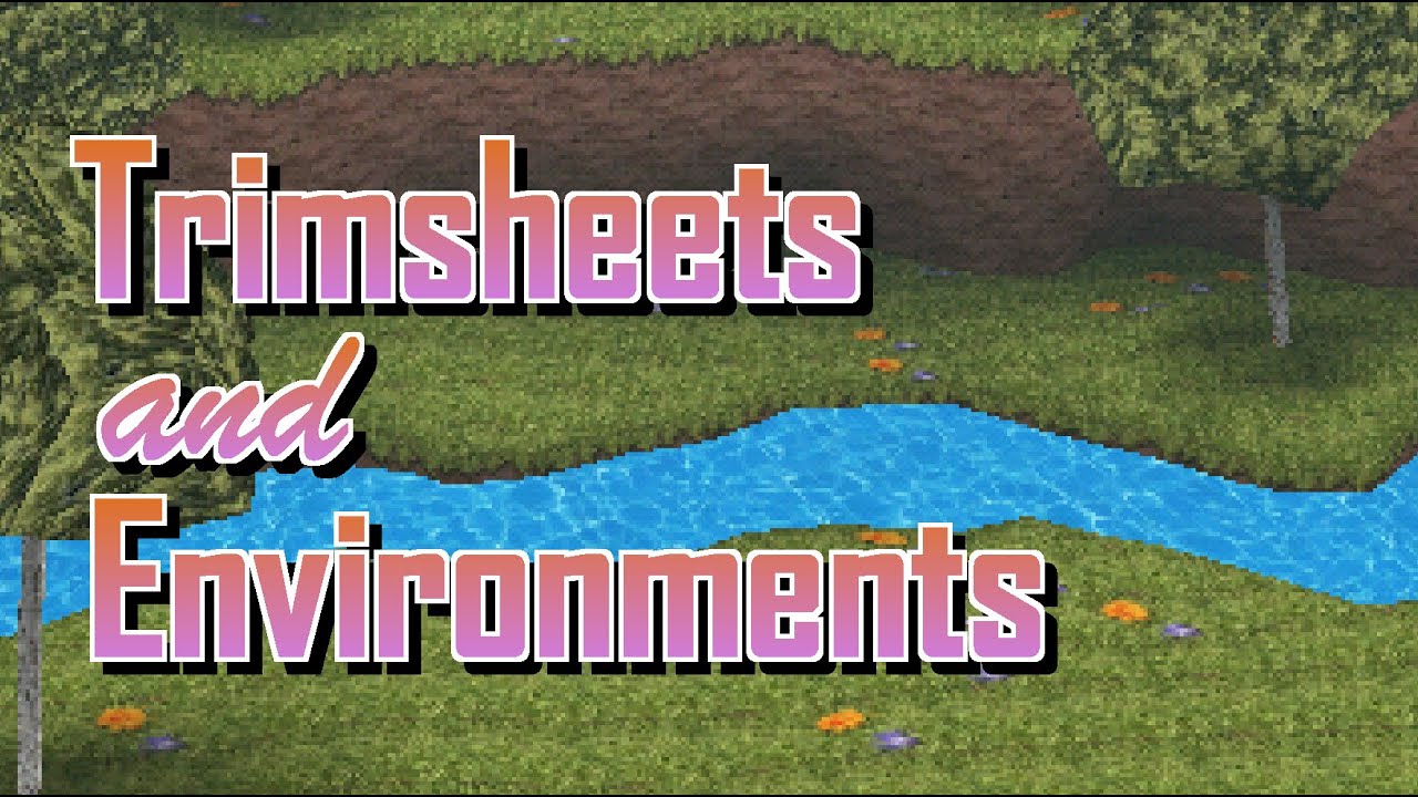
While seamless textures are good for covering large swaths of mesh, not everything consists of one uniform material or texture. There are better ways to texture our meshes, and here's a video showing you how to do it.
Thanks to PixelDough for the thumbnails and assistance with Unity
Link to the Silent Hill Level Viewer mentioned in the video: ...
but man, imagine having a whole level subdivided into tiny squares, that can not be
Well, if you're thinking about games like Minecraft, they have standardized sizes(blocks) so they don't need to deal with that.
like, imagine a dungeon from skyward sword subdivided in squares
ye, it seems that everything out of that scope is pretty hard to work with
The only decent solution I can think of is a custom shader. Otherwise you'll just spend eternity adjusting tiling on each individual object...
what u mean by a custom shader?
also, i know about crocotile 3d
As I mentioned before. A shader that samples your textures based on world space, not the uvs.
thanks to defold shenanigans i know a bunch about GLSL if that is what u mean
any tutorial or document on that? never heard of such a thing
Yes GLSL is one of the languages for writing shaders. Unity uses CG and HLSL though.
Google triplanar mapping in unity.
so 2022.2 added this but no documentation ? what does it do ? i put it in colour output and its all black

i was hoping it would give me normals from depth map but it doesn't seem to do so
I see, thanks!
When you try to material.SetColor, will it give an error if the material is null? Will it give an error if the variable isn't found?
Trying to debug this thing..
K apparently it doesn't give an error if the variable isn't found
How does everyone approach optimizing materials with few properties that needs to be changed on URP?
For example, a car will have 4 colors that will be unique per instance.
There will be like 300+ cars, and there is no material property block to save you like in built-in
How do you set hdr color intensity to 0 in code? Or alternatively how do you make an hdr color non-hdr in code?
You can reduce the intensity by dividing the color, but is there a formula for this?
Like apparently dividing a 4.5 intensity color by 10 gives it an intensity of 1.1
Try using something as an input. It probably samples the 0 index in the buffer by default.
It probably needs to be an int.
but the node says UV(4) ?
Yeah, I don't know about that. It depends on wether it's actually a buffer or a texture that it's supposed to sample. If it's a buffer, they work as arrays, so you use indexes 0, 1, 2, etc.
i also tried this:

this function exists according to forums but it apparently doesn't according to my shader graph for 2022.2
i just cant figure out how to something as simple as sample scene normals
Is that a custom function node?
yeah
Is there no node for that already?🤔
no theres not even a setting for normals to be part of the depth texture in the urp settings
but the notes say depth normals exist so im very confused
How about the camera settings?
on the gameobject?
Yes
theres just on/off or use asset settings
For depth normals?

no just depth no depth normals option
the asset has no mention of normals either

And the renderer asset?

Hmm... No clue then.
Is there a way to get main light data using shader graph in hdrp?
https://blog.unity.com/technology/custom-lighting-in-shader-graph-expanding-your-graphs-in-2019
I want to implement this function in hdrp

having a weird issue i cant figure out, ive packed a normal map into R and G, B and alpha contain masks I want to use. For some reason the RGB displays a big white border when i import the texture in unity, but the channels are correct when i check them in photoshop.

in photoshop all the channels are correct

Many exported formats will clear color information when alpha is 0, as they treat it as undefined
If you use something like SuperPNG you can get it to keep it properly
thanks, i tried it and now it works
Someone help me, I just want to pick an integer from noise of a certain range (0 to 4) according to the object's world space coordinate. (X, Y, Z)
What I got
float snoise(float3 v)
{
//3D Noise stuff
}

void WorldIndex_float(float3 WorldPos, int MaxIndex, float Scale, float Offset, out int Out)
{
    float3 worldPos = mul(unity_ObjectToWorld, WorldPos);

    worldPos = worldPos * Scale + Offset;

    float noise = snoise(worldPos);

    Out = int(lerp(0, MaxIndex, noise));
}
But im getting a lot of onion rings, don't know how to actually solve this

Onion rings

I just want to pick texture index based on XYZ!
you could remap the values so that you lerp between the texture based on the index

probably in the unity shader download in the download archive
wheres that to ?
where would it be though 🤔
then select your version and go to windows -> Build in shaders
oh i see
then you get a zip file with all build in shaders
for the URP / HDRP shaders they in there respective packages
hm no such file in the built in shaders folders either
where do you find the packages for urp/hdrp from that site
is it seperate to the examples i imported for urp
ok found it
i love how they just give a hugely complex shader script largely uncommented and expect me to understand how to now use that in shadergraph
@astral pecan

https://gyazo.com/25a9fa4a4704ab043f0b0d1a2ef40f38
Oy sort of new to shaders, anyone know why my shader behaves differently on my pipe mesh than my crate mesh? Crate is how it's supposed to look. I tried scaling down the size of the gradient noise but whatever values i choose the shader just applies its color to the entire surface no noise is created, thanks in advance

I am using flipbook to access a 2x2 texture variation.
I just need a unique index from range 1 - 4 from WorldPosition. (Preferrably through a noise)
And its difficult as heck.
:c
so you need to know how to use the different parts of your texture based on the index
void noise_float(float Index, out float Out)
{
    uint seed = uint(Index);

    float random = frac(sin(dot(seed, float2(12.9898, 78.233))) * 43758.5453);

    Out = random * 2.0 - 1.0;
}
your noise works fine as far is i can see
This is already solved, I can access the texture from different index

But this part is extremely difficult
I just want a unique index from world space to access one of the tile index
And the objects sadly isn't cube shaped, so it might go beyond its dimensions and cause onions
sounds complicated
Trying this

void FNoise_float(float Index, float MaxIndex, out float Out)
{
    uint seed = uint(Index);

    float random = frac(sin(dot(seed, float2(12.9898, 78.233))) * 43758.5453);

    Out = int(lerp(0.0, MaxIndex, random));
}

void Flatten_float(float3 In, out float Out)
{
    Out = dot(In, float3(1, 1, 1));
}
Still not working :c
Whyyyy
This is the root cause of the issue. If you don't want the index to "jump" from one value to an other when the world position changes, you need to find a way to force the position to a limited value
Is it performant to just create a lot of instance of the material instead at runtime through modifying the property?
It will be batched by SRP batcher right?
Hum, it should be batched indeed, but less isntances is always better.
But should be better than not using SRP batcher and using material property block?
SRP batcher would be better, unless you do manual GPU instancing.
I'm still trying to understand what you are trying to do :
So you have a mesh, and a texture which is basically a tilesheet, with tiles than can be randomly placed on a grid and would still display proper seams ?
And you want those tiles to be randomly applied to the mesh, based on the world position value ?
Each tile is combination of 3 2x2 tile sheet (4 variations each tile sheet).
The Top, Cliff, and Bottom.
I just want them to not be repetitive, and use all these possible combinations.
And these tiles aren't exactly cubes, so world space might not work well.
Suggestion : use the object position as source for the noise, not the pixel position ?

What the heck this works perfectly
Thanks a lot! I didn't even know this node existed
Thought Position - Object refers to the transform position itself
🥳🥳
No, it's the pixel/vertex position, in object space
What do the UVs look like on the pipe?
My guess is they're just black so your noise just samples the origin for every single point on the pipe
@karmic hatch Its just different materials with a singular color, does it still have a UV map then?
The UVs are encoded with the mesh

Any ways to add angle constraints to each axis's rotation to this billboard shader?
Such as it should only rotate at maximum 45 degrees on X axis.
Hello there, i am very new to Unity, i am following a guide about making VTube avatars, when i try to export the file as a VRM it is giving me there errors about the shaders, does anyone know what this is and how do i fix it ?

Are there any simple ways to fix this / any good tutorials that cover this sort of thing?


I want it to be smooth all the way around, and if I just use the UVs it gets messeed up at the top
Triplanar mapping
Or 3d noise function
Oh I did not know unity had 3D noise. I will look into your suggestions. Thanks
You need to add a package, there's a good one online I've used before: https://github.com/JimmyCushnie/Noisy-Nodes

GitHub
Adds various noise generation nodes to Unity Shader Graph, including 3D noise nodes. - GitHub - JimmyCushnie/Noisy-Nodes: Adds various noise generation nodes to Unity Shader Graph, including 3D noi...
That looks good! Thank you!

GitHub
A work in progress solution for capsule shadows in Unity. - GitHub - frostbone25/Unity-Capsule-Shadows: A work in progress solution for capsule shadows in Unity.
decided to release my capsule shadows implementation pubically

same kind of tech you would see in the last of us, characters/objects casting soft indirect shadows. very useful also for blending dynamic objects with static lightmapped ones
https://gyazo.com/8a391dc99cc91ef28129484f7625cc68
hello, guys
I've noticed these texture flickering, coming from the multiple overlayed textures in the shader (definitely not a polygon z-fighting, I checked)
the solutions I've found so far are made through the code and I have no idea how to do it
is there a way to fix it via shader graph?

if it's a shader made in hlsl you would have to convert the whole thing into a graph
you can't just inject shader graph code into hlsl
you can do the opposite tho
anyone know a good tutorial on how to add post processing to your game similar to the kind of post processing dani has in karlson?
it was made in the shader graph, and I'm actually looking for a solution using the shader graph
and I cannot manage to do it (
all the solutions I've found so far are via code
@cosmic prairiebasically it looks like this (don't freak out 😅 )
I use 5 layers of tileable textures, which are blended with each other using a subgraph with different blend options like lerp, masks, multiply, add, normal combine, slope mask, hard light blend mode etc
it's massive, I agree
but, in my opinion, not complex enough for unity not to be able to handle it

tell me if you want to "zoom in" at certain part of the graph 😅
In shader language, what's the equivalent of a multiply blend?
should just be multiply
or what do you mean exactly?
That works, thanks.
can i still take advantage of gpu instancing for my materials if i use the same shader but with different values assigned to the variables in the shader such as different vertex animation speed or offset values to sample noise textures?
for example say i had lots of agents but i want different colours for their albedo would they still be able to be kept together even if the output varies for each one
you could use SetPropertyBlocks to set the per innstace data
I just don't understand color mixing. If I do multiply the final image always ends up being way too dark, and if I do Add it ends up being way too bright
you'd usually use overlay or overwrite
would they still be taking advantage the performance gains though
GPU instancing GPU instancing is a draw call optimization method that renders multiple copies of a mesh with the same material in a single draw call.
it says same material but can they have different values in their properties
yes that is what MaterialPropertyBlocks are for
that whay you have the same shader and material an just a override per render so still instancing
just dont use them if you intend for your material to be srp batcher compatible
but you're doing instancing so it's perfectly fine
I'm trying to apply a gradient to my ui elements, and no matter how strong I make the gradient, you can't really see it in the ui image. It's basically only darkening or lightening the image
Isn't this how you do it?

Maybe lerp instead of blending?
multiply your gradient by a float, saturate, lerp
Also, the texture color should probably go into the base input, while the gradient into the blend. And opacity needs to be somewhere around 0.5 if you want them to mix evenly.
okay cool thanks
hmm, I think what might be happening is the gradient texture is way bigger than the main tex so it's only getting a small portion of the gradient. So maybe I need to factor in uv somehow
or maybe that's wrong, idk. I tried your guys methods and it still isn't really showing a gradient in the final tex despite demonstrating a pretty clear gradient in the main preview


why is it totally unlike the main preview

oh wait... is it because the middle part is getting stretched out AFTER the gradient is applied?
no I don't think so
Lerp value of 0 would just return the color of the A input
not sure there is a point to multiplying 0-1 values then saturating again
Where do you set the gradient texture to the material?
this looks like a waste of time

I just did it because the other person suggested
in the editor
Yeah, it should be within 0-1 range assuming the multiply input is.


it looks perfectly fine in the shader but like nothing in the actual editor when I try to apply it
Did you actually save the shader graph?
lol yes
I feel like your changes are just not applied.
is it set to ui type of shader graph too
changing lerp to 0.5 basically just made the ui image darker (closer to main tex)
show graph settings
Aah
it should be set to ui sprite

Change the image type to non sliced(the normal one, I don't remember the name). And see if it looks the same as in the shader graph?
@kind juniperby the way i solved the depth normals in the end... you have to create texture2d property and specifically name it _CameraNormals then you sample it like normal.
never would've figured it out without searching the forums lol
I see. Thanks for the info!
You mean sprite unlit?
apparently not
https://forum.unity.com/threads/shader-graph-ui-image-shader-does-not-work.1202461/ i dunno if any answers here will help but it seems others had the same issues
Unity Forum
Unity 2021.2.3f1
Shader Graph 12.1.1
This is a simple Shader Graph shader.
Screenshot1. Universal - Material - Sprite Unlit: Alpha is wrong.
[ATTACH]...
@subtle thicket
Try this and see if it works:
#archived-shaders message
lol

Hmm... So the gradient texture pattern is not visible at all.🤔
ui and shader together is so cursed...
What happens if you feed the gradient into the output color directly?
The borders are now gone, so I guess that means it's doing SOMETHING

It feels like it doesn't sample the gradient at all.
Starting to think using shader with image is just not something you're supposed to do. Guess I just have to make a bunch of more or less bespoke UI elements and put the gradient on the texture directly
It probably wouldn't change if you don't feed anything into the color.
No it actually does change when I mess around with the shader. It's just that the only thing apparently changing is the overall shade.
Which make me think that your gradient texture isn't actually set in the material(or canvas renderer somehow overrides it)
I think maybe it's only looking at one part of the gradient.. probably the middle part
What I mean is that your gradient texture isn't actually sampled.
It's not the shader issue. It's either the material issue or something about how the canvas renders it's elements.
If you apply the material to a normal sprite renderer, does it work correctly?
doesn't really look like it
no it does. It just isn't very pronounced..

yes it works for spriterenderer. So I guess it just can't work with canvasrenderer
I'm just going to scrap the gradient idea
if the gradient never changes then just make one in photoshop and leave it be
void GetUniqueTextureID_float(UnityTexture2D In, float2 UV, out float Out)
{
    float4 color = tex2D(In, UV);

    float c = 256;

    Out = dot(color, float4(1, c, c * c, c * c * c));
}
I thought this would flatten the texture into a unique number like 12345
But when I use it to multiply, it gives me per pixel result?

Have a look here https://youtu.be/ychqCohacNQ?t=90 where once the bubble reaches the target position after shooting, the adjust bubbles has an effect.
They just wobble and regain their positions.
Can someone suggest how to achieve that kind of effect?

Classic bubble shoot eliminate shooter game, exquisite picture quality, fun levels, no wifi, free, best time to pass the game!
Google Play: http://bit.ly/2Hg256y || App Store: #
~ Special thanks to Happy Dragon Inc. for this Awesome Game ~
If you love this game, don't forget to Like, share & Subscribe -
For Latest Android & iOS Game Updates...
Could be a vertex shader or just a simple cpu tween moving the graphic element of the bubble
Don't bloat your shader for temporary effects. Unless its something that's always moving like grass sway, rotation, etc.
Use tweening instead.
I've got an ice-shader. I want the light to go through and light up the other side, is that something I could do with the overall settings of the material?

No. Assuming you want "subsurface scattering", it's a pretty advanced and computationally heavy effect that needs a custom shader. Or HDRP. The default HDRP shader supports it out of the bat.
ahh I see... HDRP would be overkill. I'll just make sure the scene is properly lit then, cheers.
chriest
I guess it's in the blending subgraphs
since this is just a web of inputs
does anyone know any tutorials or ways to make a realistic looking black hole? something like - https://ebruneton.github.io/black_hole_shader/demo/demo.html?or=1000&oi=1002&os=352&sfy=474&sfp=1650&sfr=1251&ce=492&bhm=471&dd=393&do=0&dt=401&hc=1&sfe=0&cy=34884&cp=9435
I still need help, I don't get why its affecting my whole texture instead of acting like a float :c
you can always fake it by clamping or wrapping the light calculation result (the ndotl).
void GetUniqueTextureID_float(UnityTexture2D In, float2 Size, out float Out)
{
    float c = 256;

    Out = 0;

    for (int x = 0; x < Size.x; x++)
    {
        for (int y = 0; y < Size.y; y++)
        {
            float4 pixel = tex2D(In, float2(x, y));

            float pixelID = dot(pixel, float4(1, c, c * c, c * c * c));

            Out += pixelID;
        }
    }
}
This doesn't work either
What the heck :c

Nvm it worked!
Its just that 256 is too big of a number
Tried way smaller number and it worked
update: I managed to do it using TMP's shaders instead and they work absolutely flawlessly (for my use-case). Though, I'm wondering how Unity generates the Sine (Time) values so I can implement it using code instead (to control the TMP shader). Mathf.Sin exists, yes, but I would like to know what value Unity is passing into the function for the smooth sine curve
Any help is appreciated <3
To clarify, the "Sine Time (1)" on the Time node

Nvm, Mathf.Sin(Time.time); did the job ;P
You can fake subsurface scattering fairly well, but you need to write that into the shader

🔥La Biblia de Shaders en Unity🔥 El libro definitivo para aprender shaders en Unity.
👉 Echa un vistazo aquí: https://bit.ly/USB-eBook-ES
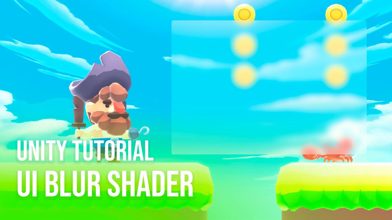
📁Descargar UI Blur Shader: https://bit.ly/gratis-ui-blur-shader
Que tal JetGuys! Somos Jettelly Team. En este video te enseñaremos como crear un efecto de desenfoque para nuestro UI ( blurred UI Image ) utiliz...

25% off your first Asset Store order, Ends December 30, 2022: https://prf.hn/l/ZQ8DnO5
- In this video, I'll show you one way to make Blur for UI elements in SRP using Shader Graph. this works with 2D and 3D. This video uses URP but I think you can do the same with HDRP too, will need to test that.
Thanks for 100 Subscribers. Hope you enjoy the...
it's in spanish
not a problem for me though
Trying to make constrained billboard.
void ConstrainedBillboard_float(float3 VertexPosition, float3 ObjectScale, float3 ObjectPosition, float3 AngleConstraints, float4x4 CameraInverseViewMatrix, out float3 Out)
{
    float3 scaledVertexPosition = VertexPosition * ObjectScale;

    float4 rotatedVertex = mul(CameraInverseViewMatrix, float4(scaledVertexPosition.x, scaledVertexPosition.y, scaledVertexPosition.z, 0));

    // Limit X, Y, and Z axis angle differences
    float3 delta = scaledVertexPosition - rotatedVertex;
    delta.x = clamp(delta.x, -AngleConstraints.x, AngleConstraints.x);
    delta.y = clamp(delta.y, -AngleConstraints.y, AngleConstraints.y);
    delta.z = clamp(delta.z, -AngleConstraints.z, AngleConstraints.z);

    rotatedVertex = float4(delta.x + scaledVertexPosition.x, delta.y + scaledVertexPosition.y, delta.z + scaledVertexPosition.z, 0);

    float3 finalPosition = rotatedVertex + ObjectPosition;

    Out = TransformWorldToObject(finalPosition);
}```
This worked like a regular billboard when the Limit isn't applied.
But I am trying to limit the angles, and its not working well. (It just stretch the vertex at certain view angle)
I need help figuring out what's wrong :c
The docs pages tells you where the nodes comes from: https://docs.unity3d.com/Packages/com.unity.shadergraph@6.9/manual/Time-Node.html and https://docs.unity3d.com/Manual/SL-UnityShaderVariables.html
https://github.com/tomc128/urp-kawase-blur
i am using this shader for a blur effect but for some reason, its rendering the left bottom corner correctly only and doing this weird stretching on the other sides


GitHub
URP renderer feature enabling a blur effect. Contribute to tomc128/urp-kawase-blur development by creating an account on GitHub.
do anyone have any idea what is the case of this ?
for some reason it fix when the change the rendering scale to 1
anyone know a good tutorial on how to add post processing to your game similar to the kind of post processing dani has in karlson?
So I've been trying to make the following grass shader work with Spot lights, it works fine with directional lights but not spot and point lights, for some reason, no colors are rendered.. Any ideas?

GitHub
A Geometry shader written for Unity's build-in Render Pipeline - unity-geometry-grass-shader/GeometryGrassShader.shader at main · Velorexe/unity-geometry-grass-shader
dont know if this goes here, but does mesh colliders affect performance
because my performance on builds suck
It doesn't go here, but yes they're the slowest collision test...use capsule if possible, or box as a 2nd option. Mesh is last resort. They're slow.
ok
because I have a room model that I made in another software and I dont want to just go through it the entire time placing collision boxes
is there another solution other than those two
You can probably do it programmatically too, adding box colliders to each object via code.
How?
I am still struggling with this
float4x4 ConstrainDirectionMatrix(float4x4 DirectionMatrix, float3 MinAngle, float3 MaxAngle)
{
    float3 eulerAngles = ToEulerXYZ(DirectionMatrix);

    // Clamp the euler angles to the defined min/max values
    eulerAngles.x = clamp(eulerAngles.x, MinAngle.x, MaxAngle.x);
    eulerAngles.y = clamp(eulerAngles.y, MinAngle.y, MaxAngle.y);
    eulerAngles.z = clamp(eulerAngles.z, MinAngle.z, MaxAngle.z);

    return ToMatrix4x4(eulerAngles);
}

void ConstrainedBillboard_float(float3 VertexPosition, float3 ObjectScale, float3 ObjectPosition, float3 MinAngle, float3 MaxAngle, out float3 Out)
{
    float4x4 cameraInverseView = UNITY_MATRIX_I_V;

    float3 scaledVertexPosition = VertexPosition * ObjectScale;

    float4x4 constrainedDir = ConstrainDirectionMatrix(cameraInverseView, MinAngle, MaxAngle);

    float4 rotatedVertex = mul(constrainedDir, float4(scaledVertexPosition.x, scaledVertexPosition.y, scaledVertexPosition.z, 0));

    float3 finalPosition = rotatedVertex + ObjectPosition;

    Out = TransformWorldToObject(finalPosition);
}
I am trying to create a billboard that has constrains on the maximum angle it can rotate. (Assuming identity is 0 0 0 degrees). Right now it just stuck on spot with whatever Min/Max angle I provide.
I don’t know if it’s something to do with my shader or some other issue: I’ve written a ray marching shader that takes about 17ms to execute in the game preview window. When I run the game it jumps up to 50-80ms, but if I alt-tab out of the editor and alt-tab back it drops back to the ~20ms range. At one point I disabled MSAA and that made the shader time drop significantly, but when I re-enabled it the shader was still running fine. I’m pulling my hair out over this because I can’t tell if it’s a problem with my code or some other issue somewhere else
I'm also getting these spikes at regular intervals:

Always test and profile the build instead of the editor if you want accurate results
Judging from the color the spikes seem to be from the garbage collector, so I assume they're because of scripts
Hi everyone.
I'm currently trying to create Wind Waker styled light volumes like seen on this picture. But I'm really struggling with the start. I've read about the approach in this blog: https://simonschreibt.de/gat/zelda-wind-waker-hyrule-travel-guide/#fireflying
Any advice on how to start? I'm using URP btw.

It was ‘rendering’ and ‘other’ so I’m not sure where to look, I have the same issue in the build
hello! does anyone happen to know some resources on appendstructuredbuffers and their performance?
I have this shader that doesn't work with Spot and Point light (shows as black instead of normal grass color), any idea what causes it in this part of the code?
Here's the section that probably has an issue:
Pass
{
    Tags
    {
        "LightMode" = "ForwardAdd"
    }

    Blend One One

    CGPROGRAM
    #pragma vertex vert
    #pragma geometry geo
    #pragma fragment frag

    #include "UnityCG.cginc"
    #include "AutoLight.cginc"
    #include "UnityLightingCommon.cginc"

    float4 frag(geometryOutput i, fixed facing : VFACE) : COLOR
    {
        float3 normal = lerp(i.normal, -normalize(i.world.xyz - _WorldSpaceLightPos0.xyz), _TranslucentGain);
        float viewDirection = normalize(_WorldSpaceCameraPos - i.world.xyz);

        float3 lightDirection;
        float attenuation;

        float distanceToLight;

        if (_WorldSpaceLightPos0.w == 0.0)
        {
            attenuation = 1.0;
            lightDirection = normalize(_WorldSpaceLightPos0.xyz);
        }
        else
        {
            float3 vertexToLightSource = _WorldSpaceLightPos0.xyz - i.world.xyz;
            distanceToLight = distance(_WorldSpaceLightPos0.xyz, i.world);

            attenuation = 1.0 / distanceToLight;
            lightDirection = normalize(vertexToLightSource);
        }

        float NdotL = saturate(saturate(dot(normal, _WorldSpaceLightPos0)) + _TranslucentGain);

        float3 ambient = ShadeSH9(float4(normal, 1));
        float4 lightIntensity = NdotL * _LightColor0 + float4(ambient, 1);

        float4 col = tex2D(_GroundTexture, i.uv.zw);
        col *= lightIntensity;

        float3 ambientLight = UNITY_LIGHTMODEL_AMBIENT.rgb * col;

        float3 diffuseReflection = attenuation * _LightColor0.rgb * ambientLight
            * max(0.0, dot(normal, lightDirection));

        return float4(distanceToLight, 0, 0, 1.0);
    }
    ENDCG
}

That does sound like a good idea. Basically taking the maximum light level recieved and surrounding the object with it yeah? Any resources to point me in the right direction?
https://docs.unity3d.com/ScriptReference/GameObject.AddComponent.html
See the bottom (3rd) example on page. For more details, see other areas of this discord, as your question isn't shader related. 🙂
Can someone help me idk why but every time I try to add poiyomi my whole pc just goes black screen mode. Everything else works fine just poiyomi dosent. I already used different poiyomi versions also re installed graphic driver and even did fcking windows updates
Literally the only thing I can't change is the bios update I did bc I need it. It's the only new bios that supports my new processor
So what i already tried 1: reinstaled graphics driver 2: used different versions for my graphics driver 3: updated windows 4: reinstaled Unity Hub+ Unity version 5: used different Poiyomi versions
everything works i can use everything in unity only always when Poiyomi loads in Black Screen
They have their own discord server, maybe ask there? Also you didn't mention what VR solution you're using.
Hi. Could anyone please tell me if it's possible to use a shader made for built-in render pipeline with URP please? If so, how?
what do you mean with URP?
you can create shader for the build in pipeline with ShaderGraph if that is what you are asking.
no no, I mean like, I found a really good cloud system that everyone in here has probably heard about, the one by Sebastian Lague, but it only seems to work with no render pipeline set in the project settings. I was wondering if there was a fix to that to be able to use it with Universal Render Pipeline
like, this is what it should look like (this is without a render pipeline set in project settings)

unless you want to rewrite the shader for URP probably not
there is no automatic conversion for that
These shaders should be the only ones I have to rewrite for the clouds to work?

i would assume but i don't know how the system works exactly so you would have to try that
I don't understand anything about shaders to be honest sorry😅 Is there anything that makes a different from built-in to URP shaders please?
Like, something that has to be changed in order for it to work?
Or just redo the whole shader?
there are some different requeremtns for what a shader must do / incude to work with URP
you may want to check out some basic URP shader to get a feel for what is going on there
the shaders are incuded in the URP package
but aren't those made with shader graph? Or they are like these that are written code?
sorry if I'm wrong, I just don't have any idea😅
you can make shader with shadergraph for URP
but most of the build in once are not made that way
you could try to recreate the shader with shadergrap depending on what shader features Sebastian did use this might work
he used something about camera views, distances and noise I think
yeah I just don't know how to do it😅
Is there a straightforward way of making a ShaderGraph with SimpleLit or Baked Lit rendering?
If not, how hard is it to add BakedLit or SimpleLit characteristics to a custom HLSL shader?
I've a question: Everytime when I try to install shader graphs in any version of unity in my project, there comes this error (you can see it in the picture), I've already tried to create a new project but it stil doesn't work... Has any one an idea, how I can fix that?

I'm trying to modify mesh data from a compute shader. The vertex color is stored as a Float16/half and I'm struggling to figure out how to read/write the half-precision data from a RWByteAddressBuffer.
I need to use RWByteAddressBuffer.Store2(uint2) to store the half4 since the uint2 written to the buffer has the same number of bytes as a half4, however I can't quite wrap my head around the conversion
can i ask about amplify shader editor here too?
I m trying to modify mesh data from a
I get unrecognized identifier error when i try to do
UNITY_DECLARE_DEPTH_TEXTURE(_CameraDepthTexture);
what am i doing wrong? do i need to include something? i am new with shaders
What are you trying to do?
Check the diffuse wrap section here
https://docs.unity3d.com/Manual/SL-SurfaceShaderLightingExamples.html
you can adjust the values here
half diff = NdotL * 0.5 + 0.5;
or maybe try clamping it (wont looks good on smooth object I think)
half diff = clamp(NdotL, 0.25, 1);
That's some interesting effect 🤔
if you dont need the polygonal light effect, you can posterize the light attenuation
But if you do need that, then yeah, you'll need the stencil shader
Does anyone know how I would go about making a shader that makes each pixel on the screen be mapped to a colour from a pallete?
Hey, not sure if anyone could help with this but I wanted to make an avatar for vrchat that hides the world around you and replaces it with a skybox shader except for players, I know it's possible, just wondering if anyone knows how to do it? and could help
I have a problem with this approach. When objects are marked as static, they seem to have one combined object position.
Because they're giving me the same variation ID each instance.
It works in the editor, but in play mode, it seems to behave differently.

Someone know how to place grass of a geometry grass shader, i tried the minon art grass painter but it s not working with other grass shader
Hey ya'll, I'm looking to get into shaders, but I don't really understand all the math that goes behind it... If you were to break down the purpose of shaders to its core, is it just having the ability to modify any pixels on the screen to appear as something else?
Whats confusing is I also see people use compute shaders to help with calculations for generating terrain or something, so its not just modifying pixels?
There isn't much to understand, Shaders are just code for GPUS.
GPU's do carry some cruft from when they were fixed function, but most modern GPU's also can be used for general computing
when you look up shaders you are likely to get pixel or vertex shaders, these are specific to two stages of the render pipeline
if you want more on general computing you can look up "compute shaders"
Shaders are just small programs that run on the gpu. Normal shaders have some standardized structure(like vertex and fragment stages) because of how most render pipelines work, but in essence they take some input(mesh data, like vertices, textures, buffers and parameters), make some calculations and provide some kind of output(in the case of normal shader, they write a color to the render target). Compute shaders also take input and provide some output(optionally), but they don't have the same rigid structure as normal shaders, so they are more suited for arbitrary parallel calculations.
If you want to maybe dip your toes in a bit you might try messing around with the shader graph

Medium
An exploration of rendering 3D objects to look like 2D pixel art sprites.
i'm trying to implement the thing on this article to a project
but i never coded a shader with text before
always used the graph
I believe that 2022.2 has support for full screen graphs if you want to take a stab at it that way
hey, how can i scroll a texture accross a cube without any edges / make it seamless?

my shadergraph looks like this

Try putting the rotate after the offset scale node
and change the time input to go through a frac
didnt change anything. mh. what do you mean with frac?
so the time value is constantly counting up, if you use a frac node it will capture the fractional element of the count, so instead of going up constantly it loops from 0 to .9999999
you need the frac because the rotation is using an absolute point for the rotation
so you are rotating the texture centered on .5 .5 and the offset is putting the texture super far away from that
If there was a way for you to avoid using rotation that would make most of this simpler
i see. got it through a fragment. well i want to move my stripe texture in a diagonal line instead of just straight
its still not seamless. i could juse a world position but then my texture doesnt rotate
So for just a simple stripe I'd say you might be better off using either the UV's or position to generate a stripe that way
i've tried to use the reactangle node but didnt get it to work
how can i make the rectangle node tileable?
simple stripe based on UV space

actually my bad drop the sine node it's not needed
sorry about earlier frac is the HLSL term I forgot that unity changed the name to fraction
what about this? how would i rotate my stripes to move them diagonally?

they way you did before just put a rotate on the UV's
well how would i rotate this stripe then? 😓

mh looks like this now. still not seamless and faces scroll in different directions

so let's back up a little bit, what are you hoping to get for this exactly?
just a simple cube with scrolling stripes, evenly and seamless
So the approach we've been looking at here would require the UV's and the shader to be set up to work together, if that isn't feasible then you might need to take a different approach
well if i have to project my uv's in a certain way in blender and you may want to tell me how, then its feasible for me :D
ok if you can do custom UV's based on the shader we've been working with I'd say get rid of the rotation, then for the UV's in blender just do a top down planar map then rotate the UV's so that the direction you want the stripe to go aligns with the U direction
if you need to preserve the base texture UV's then you can put this on UV1 and we can change the shader to accommodate it
you will also want to scale your object probably to fit within the 0-1 on the U space
alright i see where we are going. so the shader is fine now all i have to do is to set up the uv in blender to match with my shader?
yeah you just want to make sure that the distribution of the U value on your mesh matches how you want it to move across it
thats a lot of work for just some scrolling stripes. may take a while to get it right. thank you for your time.
no problem, good news is you probably only have to make it once
Hi all!
By some reason this shader code doesn't performed. What can break this code from work? I've checked frame debugger and there was no _positionBuffer / _heightWidthBuffer / _pivotBuffer like it was never used.
Issues appeared while I was updating unity to 2022.2 from beta to release
#pragma instancing_options procedural:setup

            void setup()
            {
#if defined(UNITY_INSTANCING_ENABLED) || defined(UNITY_PROCEDURAL_INSTANCING_ENABLED) || defined(UNITY_STEREO_INSTANCING_ENABLED)
                int propertyIndex = _propertyPointers[unity_InstanceID];
                float2 scale = _heightWidthBuffer[propertyIndex];
                float2 renderPos = _positionBuffer[propertyIndex] - scale * _pivotBuffer[propertyIndex];
                unity_ObjectToWorld = half4x4
                (
                    scale.x, 0, 0, renderPos.x,
                    0, scale.y, 0, renderPos.y,
                    0, 0, 1, 0,
                    0, 0, 0, 1
                );
#endif
            }
any tips how to align this right?

I'm assuming you just want it to sweep over the box, so it should probably be a top projection, I don't have 3D software on this machine but it should probably look like this:

the red that is
think of the U as the direction you want the stripe to move in
alright. thank you very much
I had issues upgrading from beta to full 2022.2 I had to do a full reimport of the shaders (my project was small enough I just did the whole project)
I am looking for the list of the standard unity shader reference names (like _maintex, _color, etc.), to use them in my shadergraph too.
I cant find them online anymore. Does someone have a clue where i can find this info?
The way I usually find them is to just select the lit shader in the packages
This the last thing I wonna try, but ok
are you answering me?
sorry wrong reply
aaaaaand fresh project doesn't help
Does anyone have any references for using Texture 2D arrays? I'm a bit of a noob when it comes to shaders, I understand how the node works but not how to loop through each of the textures in the array... feels like it should be easy but not seeing any logic for it
If you are using shader lab: https://docs.unity3d.com/2019.1/Documentation/Manual/SL-TextureArrays.html
the third component of the UV value you pass to UNITY_SAMPLE_TEX2DARRAY should set the index
so instead of being a standard vec2 it needs to be a vec3
Yeah it does, what I mean though is their should be some way to loop through the length of the array and repeat the logic for each of the textures right?
You can add a loop to do multiple samples, but there is nothing about the texture array that lets you sample multiple textures.
ah okay, what I am trying to do is probably simple, just wanted to have a sprite shader that has overlays (think clothing, weapons etc), i made that but with a set Texture2D for each layer, I was thinking array would allow me to have a dynamic amount of layers, so a character could have 1 sprite while another could have 10 while still using the same shader
thanks for the help
you want to composite multiple sprites together to make a character?
yeah, like a compiled spritesheet of multiple spritesheets
that way I can have multiple clothing, weapons etc
this seems to work but I have to define each texture seperately

it also breaks if one of the overlays isn't set although thats just my bad logic
hmm, yeah so the thing that seems like the best way for you to get the functionality you want is to create a custom loop node in the shader graph then in the material pass a number of times you want to sample from the array, and let the loop iterate over the layers that way. It definitely leaves you open to a high number of samples, but that might not be the worst thing depending on your hardware target.
sorry it is super late for me here so I'm a little out of it, the other things that came to my mind were if you instead of doing an overdraw sort of combine in the shader you instead generated a lookup texture so you could per-pixel choose the index of the texture array you want. Or you might consider jumping out of shaders completely and just generate multiple quads each with the index baked into their UV1 U coordinate and have your shader consume that
anyway apologies for not having a better answer, I really need to get to bed though
"generated a lookup texture so you could per-pixel choose the index of the texture array you want" that was actually my first idea but wanted to see if I could do it through a shader as I've not experimented with shader graph much, thanks for the help though 🙂 I'll try creating a custom node and if that fails either have a set amount of layers or create a lookup / cache of the spritesheet at runtime
im using material property blocks
but , some property of shader isnt assigned for instancing
can someone help me for the shader properties be able to get instanced?

here is the shader..
Hi guys, I've posted a question on Unity Forum. If anyone want to have a look: https://forum.unity.com/threads/hide-parts-of-mesh-overlapping-another-mesh-in-unity.1373166/ 🙂
Unity Forum
Hello guys!
I have thoses two meshes:
[IMG]
In my game, I put the hat on the hair at runtime:
[IMG]
As you can see, as expected, the hair is...
Using masking for this seems like a challenge, due to how each hat/hair combo would need an individual masking process and how hard it'd be to handle ambiguous cases where the hat and hair pass through each other
I would look into this technique instead
https://simonschreibt.de/gat/mafia-ii-hat-vs-hair/
Thank you for your answer. The Mafia thing seems to be a good aproach. However, it might be nice to find a full code solution (finding the right way to scale the hair by code, without having to set a "HairScale" bone in Blender)
You can shrink meshes with a vertex shader
I would do it based on painted vertex colors, but it's also possible to find the vertices to shrink using an object space gradient and/or the bounding volume
I was thinking to add a cylinder fitting the hat and hide every hair part inside this cylinder. But I cannot find a way to hide only a specific mesh with shader. I mean, it would hide every meshes from the scene (not only the player hair)
You could look into stencil buffers