#archived-shaders
1 messages · Page 23 of 1
Someone mentioned using a render texture to broadcast a camera looking at a sprite onto the ui... but that feels pretty janky
Is a code shader harder to work with than shadergraph?
Like ten nodes. But I'll need to add more to it later
Everything else including animation is in code form already, so I guess why not add shaders to the list
URP still uses the built-in shaders for UI, so you can grab those
What do you mean?

GitHub
Unity Built in Shaders. Contribute to TwoTailsGames/Unity-Built-in-Shaders development by creating an account on GitHub.
(I only learned about shaders like a week ago)
thats what URP uses for UI
now, you see the properties with stencil, and the stencil block? those, and the ZTest mode make it work in UI
hmm geez, that's some weird stuff going on
Stencil block is for UI masks, Ztest is to make it render in game view
so if you don't need the UI masking, you can just use the ztest mode
maybe you can generate the code from the shader graph, and just add the ztest
What would UI masking do?
the UI mask component, use one image to keep another image in its alpha
Geez, I'm looking at his built-in shader code and not understanding any of it 😅
oh nearly all of it is boiler plate
Well my sprites do use a secondary texture to get the colored glow effect. But I don't know if that counts as masking
no
Okay good! So how do you 'generate the code' from the shader graph?
Is there an automatic way or no
I think theres a button on the graph somewhere
I guess it's this one. It pulled up a 1300 line class 😅
So I guess I can't just set the ztest in here and call it a day?
well hopefully all of the unused stuff gets pulled out at some point, but yeah theyre not human friendly
should be able to

yeah, so replace the ZTest LEqual
ZTest [unity_GUIZTestMode]
with that
also save it in another file so it doesnt get overwritten next time you hit generate code
and change the name on top to you can find it when you switch the material

that just looks like its trying to parse it as c# or something
is it a .shader file?
Oh right.
I TOTALLY know what I'm doing here
hmm... I'm not seeing how to 'equip' a material with this code shader
whats the name on top

should say "Shader "Something/whatever" " in the file
might say "Shader "ShaderGraph/TeamShaderUI" "
ah ok
k moment of truth I guess
if it still doesnt work your alpha is messed up :V

the preview doesn't show alpha either


can you dm me the graph, I'll have a look
oh okay
Would be nice to hear if and how you solved it.
Hey, i tried to recreate the Height from the URP/Lit Shader. But mine (left in the video) is not working like the one from Unity(right) when adjusting the sliders:

This is only a partial answer, since I assume you're doing the same thing with the Unity side as with the custom graph side, but...
If you're doing POM, you'd usually have a height map provided. That might tell you what is going on too.
hi, is it possible to reproduce a 6 sided skybox shader in shadergraph?

Game Development Stack Exchange
I'm trying to update a skybox shader to URP and reimplement it in Shader Graph. The shader code itself is pretty straightforward, but I don't know enough about Shader Graph yet to set up the basic
thank you, but it don't fit my case. I have a render texture imported as cube
it's not possible to use render textures with cubemap 😦
now I'm trying to understand if it's possible to sample a texture imported as cube
There's a node for that.
in shader graph, if you're using a transparent graph, there's an alpha slot in the fragment node
?
Hi, I have an object with a custom shader that does not have emission on it, and I'd like to add emission
The shader is too complicated for me to mess with, it's from the asset store
My plan is to add emission in a separate shader, but I'm not sure how to do that - I tried using simple lit, but depending on my Sorting Priority, it either shows nothing, or it changes the entire look of the object (completely overrides the other shader)
How can I deal with this?
Firstly, you need to understand a few things about shaders:
- They define how an object is rendered. You can't "add up" shaders to the object as components. All you can do is either have several materials with different shaders, in which case the same mesh would just get rendered twice and one of the renders would overlap the other or they might even start z-fighting. Or duplicate the object and give it another material(but the effect is probably gonna be the same or even worse.
- Emission is usually just a color unaffected by lighting and shadows. You can achieve the same effect by just adding the emission color to your final color value that the fragment shader outputs.
As for a solution to your issue, modifying the shader (or using a different one) would probably be the simplest solution.
Thank you! This shader seems to be based on the URP SimpleLit, which pass should I edit for best results? I'm quite new to shaders, and the URP stuff is just intimidating
What passes does it have?
Maybe it would be easier to recreate the shader in shader graph?
Is it a HLSL shader?
ExtraPrePass Forward ShadowCaster DepthOnly Meta
Each except for ExtraPrePass has Tags { "LightMode"=passname }
yeah
Those are the names of the passes - I'm not sure how to better explain it
ExtraPrePass seems like the main custom thing
Forward is the one that defines the final color, so you should look at it's fragment shader.
will try!
What does the shader look like? Extra prepass is probably some intermediate calculations.
I'm not sure how to properly explain to you how it looks like - I'm kinda new to shaders in general
but yeah it seems like you're right, it mostly has a ton of function definitions, not much actual code
@robust path Been a while since I messed with written shaders, but if you see anywhere something like:
o.Albedo = ...```
You can try adding a line with
```cs
o.Emission = ...```I mean, what does it do? How does it look like in the scene?
there is no o.Albedo anywhere in the file
Is there anything pointing to albedo or color
Look for that
Look for the part that samples your main texture
or just look at the return value of the fragment shader - that's the final color.
Albedo is added to color 6 times in the forward pass
I mean it's in the code 6 times, somewhere in the forward pass
wait no
it's just
color.rgb += Albedo * mainTransmission
yep, got it! Thanks!
it works
I didn't know emission was just adding a color, huh
AFAIK, URP height effect is using Parallax offset mapping, not occlusion (different node)
To properly apply parallax occlusion mapping, you also need to provide the primitive size : the world size of what would be the UV unit X and Y axes, taking the object scale into account.


Node previews don't show transparency, only the RGB data. But to fix it in the Main Preview / Material, connect the A output to the Alpha port in the master stack.
yes thanks, just found it out
im new to this so. sry for the dumb question ll
lol
why is this my preview:

and this ingame:


thats the result when I remove bloom and global light

it really only gets white when I add my own material based on the shader
forgot to add textures

thought I didnt need to because I named the components right
but no
Hello again - I'm having an issue with custom shader graph blocks.
https://gdl.space/atexoxajov.cpp
The output of this shader is always a black square. I have a couple questions which are difficult to test myself because there doesn't seem to be a way to debug shader code:
What's the range of a float of RGBA from Sample texture 2D? I think it might be 0-1 instead of 0-256.
Have I defined my array of colour values correctly at the top of this script? I can't seem to set pOut to be a value from this array.
the function that doesn't work is PaletteMatch_float
colors are indeed 0-1
Yes, when you sample a texture it's typically a 0-1 range. So you may need to multiply by 256 before comparing
As for defining your array, I believe you should add static to the start. Otherwise it'll probably only return 0 (as the default is "extern" variable which marks it as a external input)
thanks - it's still only doing black, but now it can actually read the values, I think, so that's good
Afaik it should automatically assign the textures. _MainTex is handled by default, but for "secondary textures" you'd need to connect them with the sprite asset : https://docs.unity3d.com/Manual/SpriteEditor-SecondaryTextures.html
Make sure the name used matches the reference field of the property (under Node Settings, while property is selected that is). It's a bit different from the property name which is only for display purposes.
is there any way to make dynamic skybox in Unity?
I think there is a big limitation with render textures
It would seem my mistake was far dumber than I thought. I forgot to update the best distance value when a new best distance was found.
It works almost perfectly now, thank you very much for your help

Given something like this, would there be some elegant way of randomly offsetting my textures UV's by X whenever the Sine value reaches its lowest value in the curve?

I mean you could do something like this to generate a value of 1 around the time sin(t) = 0, and 0 any other time:
- invert abs(sin(t)) ( take -abs(sin(t)) )
- subtract some number n ( something like 0.8, so the output of -abs(sin(t)) now ranges from -0.8 to 0.2 )
- clamp between zero and one -> now all values should be zero or some small positive value
- round up
then you could just multiply that number by whatever offset you want, before you apply it
also you could adjust n to change the window that the shift is active in
if you don't want a sudden jump you could multiply by some amount instead of rounding up
@fervent flare bc I forgot to use a reply
Hey anyone know a good shader that makes good water with crashing waves on the edge of it, similar to those dark stormy nights in horror movies and stuff
There are a few high quality ocean shaders on the asset store.
Does someone know how to make an interaktive shader for grass? I already one for Wind velocity (everything pixelperfect)
how to access secondary texture via Shaderlab ? i want to implement shader to UI canvas that can get 2nd Texture from sprite editor
Question. I'm trying to manipulate the vertex positions using a texture and, while the preview shows obvious distortion, the mesh I'm applying the material to remains unchanged.


How is the mesh subdivided? If it's just a quad you're only going to be moving the corners.
Howdy peeps ; looking for some directional advice re "water":
I need a mobile (VR performant) water-shader or material of some kind. I don't need transparency (would be un-performant) or anything super fancy, I just want to give any kind of stylized impression that "this is a water surface"... Hopefully something that can work double-sidedly so that when underwater the player can see the under-side of the water surface...
the other limitations is that I'm trying to avoid real-time lighting of any kind, and that, ideally, it works for a sphere mesh (a 360 spherical water surface)...
scrolling some basic UV noise seems like the absolute simplest approach, but I was also hoping to integrate that with vertex manipulation...
So... if anyone has any insight about how i can do a minimalistic water shader as performantly as possible, would greatly appreciate it!
(the blue sphere /w the noise pattern is my current placeholder)
could u try to open wireframe and send this mesh screenshot again
alr did anyone working with softmask https://github.com/mob-sakai/SoftMaskForUGUI and using both custom shader and masking ?

GitHub
UI Soft Mask is a smooth masking component for Unity UI (uGUI) elements. - GitHub - mob-sakai/SoftMaskForUGUI: UI Soft Mask is a smooth masking component for Unity UI (uGUI) elements.
try exactly resource example of custom shader config and i got this 😦

GitHub
UI Soft Mask is a smooth masking component for Unity UI (uGUI) elements. - SoftMaskForUGUI/UI-Default-SoftMaskable.shader at main · mob-sakai/SoftMaskForUGUI
Hello! Has anyone experience with the use of Material instances for each gameobject in the built-in render pipeline?
What are the performance impacts? Especially on mobile? Would love to hear from your experiences
Hello, I'm working on a triplanar shader and I'm trying to split the top from the bottom of the normal. The goal is to have the green only on the top, and have the rest be brown


What does it look like in Unity's wireframe display?
Also depending on how large it is, you probably want a float multiplying the offset so you can change how much it's offset by (otherwise it's just a fixed 1 meter)
could multiply it by sine time or something for debugging, just to check that it's moving
@halcyon magnet With certain export settings the mesh may appear normal but get a scale of 100 or 0.01 which messes up object space effects
The rotations may get flipped which is likewise relevant when mapping a texture in object space
Hey guys! Some parts of my textures appear pink only in the build. What could be the issue?
how do you calculate the depth under a water plane?
im currently subtract the scene depth in eye space by the position node in view space
but im getting crazy bright white result when i put it in my base color
Trying to make get a 3D pixel art style going. Currently, I'm trying to figure out how to add edge highlights to sharp edges on objects that are pointing towards the directional light of the scene.
For example, this screenshot

should have highlights like this

but I'm a bit confused on how to achieve this in URP w/ shadergraph
This kinda falls under the edge outlines category(with some modifications) which is a pretty complex topic with different possible implementations that have their own advantages and disadvantages. I suggest starting from researching how outlines can be implemented in unity.
1

what causes this bug ?

2

annoying flashes
how would i go about this?
saturate output, i believe it is caused by artefacts, not sure what your code looks like
i saturate then i added a pow function
well, thats the pow function then
is it cause a value in my output is exceeding 1 ?
use pow first, then saturate
it might be negative values
since pow does not return negative values there must be some weird stuff going on at 0
how can i find 3d modelers & or animators?
good point
offer money and they will turn up
not sure if theres a room for posting ads but there are in other unity servers like UDC and GDL
hello there, i want to go from picture 1, and achieve the effect in pic 2, please help
https://cdn.discordapp.com/attachments/497874081329184799/1046235155217518602/1nnt.png
https://cdn.discordapp.com/attachments/497874081329184799/1046235188528693268/2t.png


i believe its called parallel prefix sum, but using max instead of add
but i really do not know how to implement this in a shader, i really could need some help here
please @ me so i can catch your message
So i've upgraded my project to URP and need to update one of my CG shaders, it's a very small shader (85 lines) but i'm at a complete loss of how to convert to HLSL
Essentially I have things like:
            UNITY_DECLARE_TEX2DARRAY(_MainTex);
            fixed4 _Color;

            sampler2D _OverlayTex;
            fixed4 _OverlayColor;
And UNITY_SAMPLE_TEX2DARRAY(_MainTex, i.uv)
Which are not compatible with HLSL?
Is there a good way to load a compute shader without referencing it in the inspector or putting it in a Resources folder? I'm kinda surprised there isn't a Shader.Find equivalent
sure do enjoy a nice 3 hours of trying to figure out how to get unlit materials to receive shadows in URP 🙂
and im just stuck here

Is there any way to implement transparent and double sided shaders on mobile without huge performance hit? (using a specular shader)
I don't need a translucent material, just want the holes in my texture to be transparent
ok im stuck i have a water plane and im trying to project caustics on to all the objects behind the water plane, but i seem to get stretching on the faces that vertical on the Y axis - how can i fix this stretching issue?
For something like that to exist, unity would need to load and cache all the shaders for you. There might actually be something like that in the editor namespace, but at runtime there's no need for that, so there isn't anything like that afaik.
The whole point of unlit is that they don't receive lighting it shadows.
But to help you with the issue, you'll need to share more context(like what nodes connect to this multiply).
Sounds like alpha clipping. Should be possible with an opaque shader.
is it possible to always include shaders at compilation time?
i only found a way that works in editor because the relevant interfaces dont seem to exist in build mode
What do you mean by always include?
Include where?
tbf you might also use unlit if you want to manage the lighting yourself
obviously not ideal circumstances but sometimes it's how the cookie crumbles
unity's settings menu has under the Graphics option the
"Always Included Shaders:"
...
...
index
i want to not add the shaders there
but instead in code
to include the shaders at compilation time

and not include them using unity's pipeline that processes the project settings
By "compilation", do you actually mean the building process?
i guess
I guess you could hook into the build pipeline somewhere to include the shaders..? But why not do it via the project tab..?
so i need a shader with multiple passes. right now i have 4 extra passes, one for each diagonal like this

however instead of moving it around, it would be better to just scale it from the middle like so

its guaranteed to be a plane, i just need the coordinates in terms of the plane
and im not sure how to do it
oh and also i need it to be from the centre regardless of its pivot
and scale out exactly n screen pixels on each side
also just randomly my shader stopped working, i got the message that line endings are inconsistent but i thought i fixed it in vscode
yet the shader is just pink and no warn or error messages
oh its because unity injected some code into my shader and messed it up lol
not even sure if this is possible actually
if anyone has a good pixel outline shader please let me know
ohwever it needs the be able to go outside the original sprites plane
heres what i need to figure out, a is the original size of the plane but i dont know how to get that

IDK what you mean.
if you don't know how to get (a), it is (b) -(2x). assuming they're centered.
But you'd have to know b.
You have to have one known, either a or b I'd suppose.
Yeah I'm a bit confused as to which variable you're trying to solve for here
Are you trying to solve for scale or a?
if it's scale then:
scale = b / (b - 2x);
if it's a then:
a = b - 2x;
if it's b then b = a + 2x;
yeah i need to know either a or b
You don't know either a OR b?
Or you're saying you know one or the other?
i know neither
and i need a way to get one of them at least
but im not sure if thats even possible in a shader
what data do you know and what data are you trying to find out
or maybe even better - can you explain the situation and what you're trying to do?
scale up a plane in a second pass of a shader
ive figured out the scaling by shifting the vertices according to their sign
which scales them by exact screen pixels which is what i need
but now i need to find the scale factor of that to use in the fragment shader so i can scale uvs down when i sample the texture
to use it as little as possible
I have a generic question regarding Shader Graph, as it's a visual scripting tool and if i think about the underlying code, would it be better to use a single node and just route it to several input locations?
basically, if i attach a sampler state property to each SampleTexture2D, is that generating the code required for the sampler state multiple times? whereas if I use a single property and route it multiple times is that just using one set of code? or does it not matter?
I know it's probably micro-optimization if theres a difference but im always fond of knowing these things
Do I need to declare a new sampler for every Texture2D I declare? if not, how can I determine when it's possible to use the same sampler across multiple textures?
How do I account for the offsets of sprites in my shader.
Texture number one is a texture split into multiple sprites (actually its a tileset)
Number 2 is world space auto tiled. It seems to add the offset of the sprite on the tileset to the offset though. So aligning tiles doesnt work

any idea why this isnt working?


and the object looks black
if i do return float4(1, 0.8, 0, 1) it works
Your property is named coluor but colour in hlsl
how can i make a compute shader having a starting point, and checking anything before, comparing those 2 values and return max of both of them?
basically, i want to go from picture 1, and achieve the effect in pic 2, please help
https://cdn.discordapp.com/attachments/497874081329184799/1046235155217518602/1nnt.png
https://cdn.discordapp.com/attachments/497874081329184799/1046235188528693268/2t.png
please @ me for suggestions
why the hell is ComputeWorldSpacePosition function not available in shader graph yet they have that function in their api
is there any way to have a shader use global positioning to make all objects using it have the texture line up? Like blenders "object" mapping option in the shader creator. right now all the meshes in my scene are somewhat different sizes so i end up making a whole new material to kind of line them up and i cant imagine thats good for file size
strange, when i apply a local to world matrix to my material it doesn't seem to update 🤔
Use world position as uvs in your shader.
This is a problem that can't easily be parallelized, so I wouldn't consider a compute shader to be the best solution.

You can do one each way an examine the code. The optimizer might just optimize excess samplers out, but I wouldn't count on it. If it were me, the most intuitive is to use one sampler and drag multiple output lines out of it to various things.
found like 3 different tutorials but got a different broken result from each of them and none of them gave a github repo 👍
doesn't help that pretty much every github repo for such a thing is a post processing shader rather than just a normal material shader
If anyone has any github repo examples of outlines using depth normals in URP that is a single shader made in shadergraph that'd be great because I literally do not know how to continue
@karmic hatch @grizzled bolt I appreciate the help. The solution that worked for me without changing the wireframes were the following nodes:

Is there a way to override final blit pass to use our own uber post process shader?
i wouldnt know of any better solution than having a starting point, and checking the next (segment maybe?) whether its bigger or not, deciding max(x,y)
What do you refer to by "final blit"?🤔
how do i do that exactly?
im not a 2d artist how to make 2d shaders like cool shaders for unity ?
it's a pass in URP that's literally called Final Blit
Depends on wether you're writing the shader manually or using a shader graph. In the latter case there's a position node that you can use to sample the texture. In the former it's a bit more complicated.
Hmm... I don't know much about the inner workings of urp. Might be worth asking in #archived-urp.
how do apply a normal map only to the faces that have a normal facing up in world space
i applied my approach to colour and it looked fine
but as soon as i apply it to the normals it affects other faces
this is what i got

the idea being then if the face has a normal of (0,1,0) i multiply by 1 or i multiply by 0
but it messes up entirely
Could get the dot product of the normal vector and world up direction and push the resulting value through a step node to set anything below 1 to 0. Then use the resulting value as the mosifier.
yeh i figured it out in the end its because the object was rotated 90 but there was like 0.0001 off so the step was rounding it up to 1 so i have changed the threshold now
damn float precision got me
im still struggling to understand if you need to multiply or add colours some times
im trying to add stronger caustics but its causing the blueness of the water to be less vibrant
very confusing on how im suppose to merge it to the colour of my water

can i make this a shader in unity
and can it work with triangulated ngons?
also each face is a seperate object in my project
idk i'm no shader god
https://www.youtube.com/watch?v=fu5HYNu-lw4 try this ?

Improving our existing wireframe shader, to only render quads. This removes many of the diagonal lines from the mesh you may not want.
We use the technique of longest edge removal from the triangles. This removes the majority of cross diagonals in a mesh that is predominantly made of quads. It isn't perfect, but if this is the effect you requir...
i didnt go in deep yet sound like its should be your desire ?
I am sure this is possible with shadergraph too
It's not all that different from c#, syntax-wise

i exported height map from substance painter, but its adding like a outline to my character, how can i fix it?


If your height map uses black as a "neutral height" color, it'll be interpreted by unity as an indentation, and basically shrink the texture which makes pixels outside of the UV island visible
This will also happen if you use grey as neutral, but if the texture is marked as "sRGB"
Hi I've been using a halftone shader i made and it works flawlessly.. Until there is a flat surface. It works great on bent surfaces as you can see on the horns, the back and the leg parts, but holyy is it so bad on flat surfaces like the gun or the two legs you can see in the other screenshot.


Hey all! How can I separate channels for the camera?

What do you mean "separate channels" ?
Notes :
- The camera position is float3, not float2
- You can use _Camera_Position.x, .y or .z to get individual axis values but ... I still don't see what you want to do.
Yea the float2 was just me playing around. https://www.youtube.com/watch?v=4P9Bifze8QY&t=609s
I'm kinda using this as a guide. I want to split the channels and just use X and Y. Honestly not sure why but I'm just following how he made it.

Blender Artist topic: https://blenderartists.org/t/impostor-baker-add-on/1209475
Download for Blender 3.1: https://drive.google.com/file/d/1pNL-RDvsfX9gUseHEO6O_F1bbXr8FedQ/view?usp=sharing
Download for Blender 3.0: https://drive.google.com/file/d/1zRLV0pH9jN9itLhZDHC7DaNl-me5Rw1c/view?usp=sharing
Download for Blender 2.9: https://drive.google....
anyone know why this shader isnt mapping to Y or Z correctly?

Are you using the world position as UV input for sampling ?
UV is a 2 coordinates vector, so the Z value of the position is ignored, and you are projecting the texture on the XY plane
If the model has proper UV coordinates, just use them with texture coordinates node, or use triplanar mapping node for world space coordinates
thanks, i couldint fix it, so i removed height map xD
triplanar worked. thanks
Does ComputeScreenPos do anything special to stretch the resulting normalized value somehow? Because I'm trying to use id as screenposition in a compute shader, however to get textures to work I have to add -1 after the texture width/height, which doesn't even work accurately all the time.
like (id.xy / (screenSize.xy - float2(1,1))) * screenSize.xy maybe to stretch it out?? not sure what the proper way to deal with this is
^this seems to work at least...
Hey folks, I'm playing with simple parallax shaders and stumbled upon the classic "View Direction drives the offset" technique, which works fairly nicely. However, at more extreme angles the effect breaks down and the textures flatten. I think this is a common issue with the technique (as I've seen many games have the same side effect), so I'm wondering if there is another way to approach the effect, even if it's a bit more expensive?
Why is there so much stuff missing now in shadergraph compared to what I'm seeing in these older tutorials?

now it's like this

I can't figure out how to replicate these shaders because stuff is missing, like alpha clipping, smoothness, emission, etc
I guess sprite mask is the same as normal
I'm trying to replicate a dissolve shader btw
Well I figured out step node is basically the new alpha clip
Well, not "new" since it works the same way in all situations
Alpha clipping is a particular way to do semi-transparent surfaces, usually for materials that are otherwise opaque
Sprite Lit doesn't use it because it's transparent to begin with
Sprite Lit also doesn't have smoothness or metallicness because 2D lights don't consider that
you can add more onto the fragment shader
i believe if you right click on it it gives you things you can add
there are a lot
also i think alpha clip might need to be ticked in the graph inspector?
Ah, thanks
Tst, I forgot the golden computer rule. When in doubt, right click everything
I guess the Sprite Lit could use emission, but for some reason doesn't
Yes, I believe adding block nodes to the stack doesn't by itself do anything if the shader doesn't support that block
The problem here being that Sprite Lit does not
Yeah you still have to use step node
Anyone knows how can I fix this issue?


I just put my blender work into unity and that's what I got (view first image from top)
You sure this is a shader issue? Just seems like a materials/texture issue
how do we write code for lit shaders in urp the docs only show an example of unlit shaders
I need some help adding a random offset to a texture every x seconds
how do I get the time node to turn into a sort of periodic timer ? 🤔
Hey, quick question. I've got this gem (sry for the quality, it's an AR screenshot) and I'm trying to change its color values on buttonclick.

When I click the button, it changes the color, but it suddenly becomes a lot "brighter", causing the loss of reflection details

But the only thing I'm doing is editing the color values through script. Alpha is excluded already, because it's 255 on all of them so the only values changing are the RGB values
sharing the code would be a good first step
Well, in that case it's just public void Red() { _gemMaterial.color = new Color(255, 0, 6, 255); }
_gemMaterial color is public Material _gemMaterial
does shader graph automatically account for what platform we are using for things like returning depth values because on some platforms it uses negative z
Color uses 0 - 1 values
everything you give it over 1 is going to be the same as 1
so your color is full red, full blue, full alpha, zero green
I'm still getting different colors though. Wouldn't I get the same color everytime if that was the case?
wdym
same color every time you do what?
Anyway you don't have to take my word for it
read the docs:
https://docs.unity3d.com/ScriptReference/Color.html
This structure is used throughout Unity to pass colors around. Each color component is a floating point value with a range from 0 to 1.
I'll go ahead and change it. Thanks for the answer
actually looking back on this i think i want something a bit different

The mesh

with diagonals removed

what i want
basically to just inset the edge of each shape
i've heard that you can bake some of this information into the mesh but i might still want to have meshes imported at runtime
You could loop the mesh vertices, identify the outermost corners, sort them in order and use to render separate lines either with a line renderer or a custom shader(not entirely sure about that one).
It would only be possible with convex shapes though I think .
Might be possible with concave too. But it would be several degrees of time more complex. Both computationally and implementation wise.
i was thinking maybe a multipass shader would work
scaling down each object then overlaying it ontop of the original
each face is a seperate object
but i'm not sure
Ah, of it's just the outline that you need, there are many techniques to get it done. Look up tutorials on outlines in unity.
is it much slower?
What is much slower than what?
a wireframe shader alternative
i imagine rendering each polygon twice could be bad for performance
Not sure what you mean by a wireframe shader since we were talking about outlines from my understanding.
But rendering the geometry twice is of course gonna be slower than rendering it once.
hmm. It's difficult/impossible to see depth with my toon terrain shader. Any idea on how I can fix this?


this isn't a shader based fix, but perhaps you could imply depth by using objects of a standard size
eg, flower bunches, trees
any one know what this means for my custom code?
void RGBSplit_float(float split, Texture2D Texture, SamplerState Sampler, float2 uv, out float3 Out)
{
    float2 offset = float2(split,split);
    float r = SAMPLE_TEXTURE2D(Texture, Sampler, uv - offset).r;
    float g = SAMPLE_TEXTURE2D(Texture, Sampler, uv).g;
    float b = SAMPLE_TEXTURE2D(Texture, Sampler, uv + offset).b;
    Out = float3(r,g,b);
}

what's line 303
well according to the show generated code its literally just a comment line:

this is a custom function im using thats in its own hlsl file
not sure how exactly to get it to show me the exact line causing the problem
does my hlsl file need to include something for it to work ?
I'd check if you have other errors.
where would it list other errors
If you select the shader, they should be displayed in the inspector
the inspector for the SG only has this showing

Hmm
maybe i need to restart unity or something
does my code look fine on the face of it ?
Perhaps the issue is not with the code but the custom function node settings?
I think it's fine.

Did you define the entry/exit nodes correctly?
had uv set to float and not float2 but fixing that didn't change anything
it seems to talk about sampler and texture2d so i presume its the three lines involving the SAMPLE_TEXTURE2D
wait do the variables in the inspector have to be in the same order as the function's arguments
Yes.
Probably the float/float2 issue use the cause and after fixing it, it just didn't take effect right away
it seems to be ok with my variables not being in the same order as the function's parameters which is odd
Are they not? They seem to be from what I can see.🤔
Ah, the uvs and split are mixed up?🤔
Was pretty sure the order matters. Maybe your input gets cat to the other type?
But if it doesn't, that's interesting.
i thought it was because they match by name
Ah, could be that indeed. Didn't think about that.
ah damn it similar error popped up this time
even made sure all the variables matched and were in order
apparently cant convert UnityTexture2D to Texture2D<float4>
same function yet it was error free just moments ago
I guess the type used by the shader graph is UnityTexture2D. That's a wrapper around Texture2D if I get it right.
how do i get the Texture2D then to use the SAMPLE_TEXTURE2D()
Thinking about it, do you really need a custom function there? You can do that math in the shader graph itself.🤔
well im calling it a few times and it just makes the graph neater
its becoming spaghetti
Could make a subgraph or something, but okay.
Make it a subgraph in a subgraph.😬
Check the manual page on how to sample a texture.
https://docs.unity3d.com/Manual/SL-SamplerStates.html
It should work without a macro. In fact the way you're doing it know could be the CG(built-in rp) way..?🤔
Hmm. Maybe not. The shader graph node uses that macro it seems.
its weird because in the subgraph theres no error
but using the subgraph in the main graph the error shows
in the subgraph its fine

Perhaps it didn't recompile it?
is there a way to force it
Press the save button?
i do
Where does it show up though? And what exactly does it say?
in the main graph

when i use the subgraph node
but if i open that subgraph
theres no errors in there
What does it say?

What if you close the graph window and reopen it?
hm that got rid of the error but now generates a new error in the console 🤔
Shader error in 'Master': undeclared identifier 'r' at Nodes/WaterAPI.hlsl(7) (on d3d11)
I think the issue is with the macro. Try using the way they do it in the docs page.
oh you mean from the texture itself ?
this is what i was referencing from when i wrote mine

but i wrote mine like this:
    float r = SAMPLE_TEXTURE2D(Texture, Sampler, UV - offset).r;
    float g = SAMPLE_TEXTURE2D(Texture, Sampler, UV).g;
    float b = SAMPLE_TEXTURE2D(Texture, Sampler, UV + offset).b;
Yeah, I've seen that too. But I just don't trust macros.
ill try the other way to test it then
It could be that you pass in an expression to the macro or something. Since they're evaluated at compile time, who knows what it's expanded into...
hmm now i got a new error entirely Shader error in 'Master': undeclared identifier 'OffsetUV_half' at line 198 (on d3d11) i've not even got anything with that name
seems to be happening every where

wonder if unity is just failing to compile properly or something
Hmmm... Does it appear in a compiled shader code?
it seems to keep taking me to a random line with nothing there
dunno why these errors are so poor at telling what line it is
that texture error also seems to remain aswell

(╯°□°)╯︵ ┻━┻
Share the updated code.
void RGBSplit_float(float Split, Texture2D Texture, SamplerState Sampler, float2 UV, out float3 Out)
{
    float2 offset = float2(Split, Split);

    float r = Texture.Sample(Sampler, UV - offset).r;
    float g = Texture.Sample(Sampler, UV).g;
    float b = Texture.Sample(Sampler, UV + offset).b;

    //float r = SAMPLE_TEXTURE2D(Texture, Sampler, UV - offset).r;
    //float g = SAMPLE_TEXTURE2D(Texture, Sampler, UV).g;
    //float b = SAMPLE_TEXTURE2D(Texture, Sampler, UV + offset).b;
    Out = float3(r, g, b);
}
i dont get why its saying converting UnityTexture2D to Texture2D<float4> though
the code seems fine it just seems to not understand the type
The other way around.
wdym
It can't convert Texture2D to UnityTexture2D.
no it says UnityTexture2D to Texture2D
Check the shader graph manual page on custom function node. Preferably version above 10.3.
See the last section "working with texture wires"
I think that's relevant.
It's definitely the other way around in the screenshot.
it says UnityTexture2D to Texture2D<float4> for me

It says the opposite here though.
Anyways, check the docs page.
yeah reading it now
I think the error was making sense all along. Although, not being very descriptive...
right so i have to use type UnityTexture2D not Texture2D in my hlsl code
no lol apparently that type does not exist
guess i got to find what file to include in my script to get it work
pain
urp
Okay
whats birp
Built-in rp
ohh
im on version 13 and still get these problems lol

do you know the location of unity's hlsl files to use #include ?
Actually, I don't think there's a need in include. Since it's part of the shader graph, unity should include all it needs.🤔
Sorry I went to sleep, also yeah it is a texture issue I just couldn't find the texture/materials channel 😅
but is there any way to fix it?, I worked really hard on that model
make sure your materials are correct
I tried saving a very simple blender project which contains a cube and a checker texture, that's it, and the checker texture did not work am I missing something?
yes do you understand how materials work in Unity?
Blender materials do not generally transfer to Unity
I didn't know that 😅 ... , watching a tutorial rn of how to export
everyone tells me to 'unpack all into files' but I don't have that option??


try UnityTexture2D and UnitySamplerState
do i need some include file to use them ?
nope
a quick test seems to not find them

or is that because my hlsl file is standalone but shadergraph will combine it ?
did you actually save the file 😛
yeah its my visual studio saying it
ok, I dont use the suggestions for shaders, its no use
ah lol
it works out of the box in this version
void Test_float(in UnityTexture2D _Texture, float2 UV, in UnitySamplerState sampler_Texture, out float testing)
{

     float r = _Texture.Sample( sampler_Texture, UV).r;
    testing = r;

}
The quick test I did
is in important there?
oh the name needs to be sampler_TextureName ?
copy pasted your code and got this:

i swear it doesn't regenerate or something
i dunno why its talking about Result_0
i have no variable with that name
theres two _ _ there in __Texture I dont know if that makes a difference
also you didnt at a UV
Vector2
oh i seem to have to close shader graph and reopen for the error to go away
thats annoying

for some reason if i edit the code and hit save it wont update in shader graph until i reopen the entire shader graph
at least it works so thanks for explaining the issue with textures @neat hamlet !
shader graph can still be buggy
glad its working now
the docs do not do a good job at explaining so many things as a beginner 😄
constantly having to dig forums
even for a non beginner its not easy :V

Hi guys I have been trying yo implement metaballs, and use the code from this repo https://github.com/luke161/Unity-Metaballs-2D
This generated the metaballs on 2d objects but i wanted to generate metaballs on the UI and have no clue where to start from. Any help is appreciated.

GitHub
Implementation of 2D Metaballs with marching squares in Unity. - GitHub - luke161/Unity-Metaballs-2D: Implementation of 2D Metaballs with marching squares in Unity.
Anyone know if this is a correct way to approach it?
I created this Shader to draw a perfect circle for one GameObject, but in 2D it does not respect Sorting Layers. I figure it, because i'm using a LineRenderer and the line overlap the material using this shader, but it doesn't when i use a material that uses Sprite-Lit-Default.
If i use Sprite-Lit-Default, it respect Sorting Layer. Is there something i can do in the Shader Graph that makes sure it works respecting the order of my layers?
I read i post in "stackoverflow" (but it is an answer from 2015) that in the shader code it needs to add
ZTest Offso it wouldn't mess with the layer order.
Is that true? Or is there something i can do in shader graph ?

Hi I've been using a halftone shader i made and it works flawlessly.. Until there is a flat surface. It works great on bent surfaces as you can see on the horns, the back and the leg parts, but holyy is it so bad on flat surfaces like the gun or the two legs you can see in the other screenshot.


@stable flare i think this is sort of an inherent quality of flat or near flat shading unfortunately
I have seen some art styles use painted edges and specs as pseudo-texture, but otherwise i think you could try and use bumps/ridges in your geometry to help ensure that your half-tone shader has places to transition on
eg:

ridges placed like that should at least impart some shading that helps with direction and depth
i really like the style but ultimately it does seem tough to work with 😄
Anyone know if its possible to add an offset to a textures UV's every X seconds?
Been trying to crack this since yesterday without using a c# script to control values
cannot figure it out though, it seems like shaders cannot store any data
shaders can't store data.
A material is basically a shader + parameters for the shader. You'd adjust some parameters on your material to do this
also the shader needs to support the params
I figured as much... so what I am trying to accomplish, is it not generally possible ?
adding amount X to an offset every Y seconds
of course it's possible
as long as your shader supports UV offset as a shader param
is it easy? would you be able to point me in the right direction?
I mean... what shader are you using?
Most of the default unity shaders support a UV offset already
https://www.reddit.com/r/unity/comments/z81jzs/material_for_image_ui_causing_random_black_bars/
basically my material on my UI Image is causing a blackbar
removing the material fixes the issue...but then my eyes look wacky so was hoping someone knows a workaround
got this advice from someone
"Looks like a shader issue to me, the EyesPaint material has the wrong one, or something wrong with it. Probably ask in the shaders channel"
reddit
0 votes and 0 comments so far on Reddit
nvm
"Oh, UI doesn't support Tight packing, and all our sprites has it enabled."
Well I am trying to create one in shadergraph. One that adds an offset of X every Y seconds. But without a C# script.
I just don't know what node sorcery produces this result
Use the add node
add your parameter to the UVs
and feed that result into the UV for sampling the texture
that's all
that doesn't add the value every y seconds though
I am trying to do this only in the shader, without using a c# script (that's the thing)
you do Material.SetFloat or SetVector and feed data into the shader
why
it's quite standard to drive this stuff from the C# side
I imagine so, but is it possible without it ?
sure, there's the Time node
You'll just have no control to pause or manipulate it at runtime.
So I'm currently into premature optimization, but before committing to a technique I want to ask for you guesstimation: I've been considering writing a terrain renderer that works soley by tessellating single quads and displacing with a height map. Tessellation factor being controlled by cam distance. Now there are voices that tessellation is expensive and only pays off in some cases (and especially only when having a dynamic height map). 15 years ago, bandwidth was a concern, but is it now better to just have a "high poly" grid and eat the bandwidth and potentially increased vertex count (in case I don't manipulate the mesh based on the camera position on the cpu, which again, would cause updating buffers). [i.e. keeping the terrain rendering as is?]
How would I go about doing that ?? Could you point me in the right direction ?
I don't really need any control over it, so that should be fine
I know how to add value X to the offset every frame relative to time but I don't know how to amount Y every S seconds (using the time node and without using c#)
to do what? Use the time node?
Put it into the graph
it has a bunch of options
it just produces a number based on the time elapsed
(or other things depending on what setting(s) you use)
I don't play the negging game
I am trying to add an offset of amount X every 1 second only
not every frame
that is what I have difficulty with
I know the time node exists
And I know that I could do this with C#
is the timer on a per object level or for the whole world?
you could do it like this

(in the example the offset defined in the multiply and it gets added every 5 seconds
If anyone here can provide me some information on this ?
if you have two colours A,B and you use min() on them...what makes a colour more min than the other? are darker colours considered more minimum ?
so like a light blue vs a dark blue would min pick the dark blue
i want my shader to pick the darker colour of the two so i assumed min() would do that - if not what is a better way
Thx man
min goes componentwise and takes the min of each
so if you have (1, 7, 2) and (4, 4, 4) the result will be (1, 4, 2)
oh
ok i dont want that then
is there a way to pick a darker colour from two choices
maybe the magnitude ?
sure - convert the colors from RGB to HSV form and select the one with the lower V
oh wait magnitude wont work either
is that easy to do ?
here's some hlsl examples
https://www.chilliant.com/rgb2hsv.html
thank you !
Does anyone know of a shader already created that can take an audio file added as a component to a 3D object and control transparency?
In URP ideal, but not necessarily critical
Hi guys.. is there a shader which will only let the material appear under certain colors of light? Eg. words on wall with a blacklight
for urp*
Have you had any luck using light layers in your own shaders? We're quite stuck.
There might be somewhere in the world if anyone ever needed that functionality and created a shader for it. But the chances that it's available online are quite slim.
Yeah I'm struggling real hard to find anything online for it.
Which just means that you need to write your own.
This is the closest I found, a reddit thread. https://www.reddit.com/r/Unity3D/comments/6inj6q/uv_light_reveal_effect_made_with_amplify_shader/ But it was done with Amplify 5 years ago.

reddit
23 votes and 8 comments so far on Reddit
I tried messing with Shader Graph, but I have no clue how it works lol.

Shaders are executed on the GPU they have no clue whatsoever as to what going on on the CPU side.
If you want a shader to use some data from the CPU side, you'll need to upload it to the GPU either as a texture, buffer or a shader parameter.
You'll need some kind of check or a function that transforms color data to transparency.
if i use the same subgraph twice in my shader graph is that calling the subgraph functions twice ?
for example i have a depth to world subgraph. i need the result used in a few places - can i just copy paste the subgraph and that will still only be one call or will it be calling it for every copy of it i use ?
because its becoming spaghetti lines every where and its annoying as hell
Nah, I think that would call it twice. Visual scripting with complicated logic is gonna turn into spaghetti inevitably.🤷♂️
damn
i would write the code but its a lit shader and no docs on how to write a lit shader only unlit
Use the connectors or whatever they're called. They can help you move the wires to the side so that they don't overlap other nodes/wires.
yeah i'll have to
This part I understand, I guess the next question is has anyone translated audio volume level into data and how were they able to do so and then add that as a shader element.
The audio data you can probably get from the audio source in some form. You'll have to research that since I don't know much about audio. Then you need to normalize it on the C# side so that it corresponds to transparency value(0 to 1). Finally set a material property to move the data to the shader(might be easier to adjust the main color property's alpha)
any one know a guide to writing lit shader code
unity only has docs for unlit shaders
which is annoying
for which render pipeline
URP
ideally also HDRP but URP for now
i dont want to touch the actual lighting stuff - just want to write the visuals of the mesh before the lighting
i have no need for custom lighting etc
right now i use a lit shader graph but its becoming so complicated that i would rather write it in code
yeah idk lol.
One thing you could do is take your shader graph and view the generated shader
and go from there
yeah >_>
dunno why it has to be so ugly looking
that's kinda how generated code works
one thing im considering as an alternative is one giant custom node function
yeh all the examples in the docs are unlit 😆
and just write a massive function
It's not really supposed to be read by you.
And the compiler doesn't care how ugly it is.🤷♂️
i know but they haven't provided an easy way to write custom lit shaders by code
You could try looking up the standard shader source code and copying some of it.
If it's the urp standard shader, yeah.😬
what about in hdrp ?
You'd need an HDRP shader.
Maybe look at that. Someone made a urp lit for learning purposes.
https://gist.github.com/shivaduke28/b224ebaebf4d70b7bd7ad396ecf2af31
Or this.
https://gist.github.com/takumifukasawa/f5a2878a1c35847365fe07146ff4156d
Basically just search GitHub and you'll get tons of results.
any one know how to convert depth node in eye space to be linear
it apparently isn't linear which is annoying
can you mark vertex as not to render in vertex shader, so it doesnt render any triangle with it
?
that would also skip two other vertices with that associated triangle so the only way would be to swap the winding order in the vertex array
could do that in a buffer of vertex data then pass that to the shader from compute shader for example
basically you would be flipping the normal of the triangle
but thats really only skipping for the fragment shader not the vertex
Heyo fellow people.
So ive got a weird question for shadergraph.
I currently calculate the distance between two vectors, but i would rather like to keep track of what the current smallest distance is .
e.g if distance = 3 (store 3)
later distance = 1 (store 1)
later distance = 2 (store 1)
later distance = 100 (store 1)
Later distance = 0 (store 0)
The purpose of this is im making a beard cut shader but i need the hair to stay cut
The way i would do it in a script for unity is :
public min = 100;
public float distance;

private void Update(){

  distance = Vector3.Distance(ThingA,ThingB);

  if (distance < min){
      min = distance;
    }

}
This code would store the smallest value that this distance has ever been, but i have no idea how to translate this into shadergraph 😖
If anyone has been following this , I think a soln could be to store a number that i can compare to.
The problem is i cannot find a way to store a parameter to refer to again. The easiest if there were a setFloat() node equivalent inside shader graph.
Shaders don't really have variables that persist between frames like that. This would be better handled in C# and send into the shader via a Float Property, material.SetFloat("_Reference", someValue)
Ah i see. Ty for the response ❤️
But ive also realised that any property will be shared amongst all vertices, but require each vertex to store this distance.
I was so close to making this system and now i feel so far 😦
Considering there are logic gates im thinking of trying to create a flip flop of some sort and see if that works
Easy peasy. Make that calculation in a compute shader and save to a buffer/texture.
And reuse it wherever.
Or do calculation in C# and store in mesh data, via vertex colors or an unused uv channel
Great idea
Smort, ty
I'm trying to use some concepts from here for my custom ray marching code: https://github.com/SebLague/Clouds/blob/master/Assets/Scripts/Clouds/Shaders/CloudSky.shader
I'm using shader graph, so I'm trying to implement some equivalent functions.
float4 frag (v2f i) : SV_Target
            {
             ...
             float viewLength = length(i.viewVector);
             float3 rayDir = i.viewVector / viewLength;
             ...
             }
I have implemented as:

float viewLength = length(viewVec);
float3 rayDirection = viewVec / viewLength;
And this:
                float nonlin_depth = SAMPLE_DEPTH_TEXTURE(_CameraDepthTexture, i.uv);
                float depth = LinearEyeDepth(nonlin_depth) * viewLength;
Has been converted to:
depth *= viewLength;
Where depth is from the scene depth node shown above
But it seems no matter what I do, I just get a transparent cube
So the following happens next:
I get the distance to the box and distance inside the box, and advance the ray origin to the point that it intersects the box
I then need to set the step size, to do this I calculate (1 / numSteps) * dstInsideBox
and advance the ray using: rayOrigin += rayDirection
To convert from world coordinates to sample coordinates I do the following:
float3 samplingPos = ((rayOrigin - objPos) / objScale) + float3(0.5, 0.5, 0.5);
Where objPos and objScale are the world positions and scales of the cube being raymarched
A few things I'm unsure of:
- Is the world view vector in shader graph the equivalent of
i.viewVector? - Is the scene depth node the equivalent of calling
SAMPLE_DEPTH_TEXTURE()followed byLinearEyeDepth()?
how do i get somehting like the Is Front Face in shader code
For vert/frag shader can use the SV_IsFrontFace sematnic. So like, bool isFrontFace : SV_IsFrontFace in the vertex input struct (or param in vertex function).
For surface shader you'd want to look into the older VFACE semantic instead.
- Should be yes
- You'd want to use "Eye" mode on the node to replicate
SAMPLE_DEPTH_TEXTURE() > LinearEyeDepth()
Hey, I'm a complete shader noob here so I apologize. I'm trying to make a Shader with Amplify that changes it's opacity or translucency based on a certain color light hitting it, think Blacklight or a Reveal Shader. How would I go about doing that? I apologize, but would appreciate some better understanding.

Why is unity throwing this error in this line?
Shader error in '': Parse error: syntax error, unexpected TVAL_ID, expecting TOK_SETTEXTURE or '}'

Hi. I've got a problem. I just added post-processing to my VR project but it change my shader in a weird way : it duplicate the result of my shader (I just need the bottom in the second screen). How can I achieve that please ?


When using bloom, you want to enable HDR rendering if you haven't already. That allows pixels to be brighter than 100%. Your bloom threshold is set to 90% now, so any pixel brighter than 90% will have bloom added to it. If you have HDR enabled and your threshold set to 100%, you can make sure your shader doesn't contribute to bloom if you clamp/saturate the color to 0-1 before outputting it.
Alternatively, you can clamp it to 0-0.9 if you don't want it to contribute to bloom with 0.9 threshold, but that will also make it darker.
Sorry, I think I misread the question.
I check HDR mode and I add the Threshold but that dosen't change anything x(
the post process is for an other shader (outline) but for this shader I don't need post process so how can I avoid that please ?
Try clamping/saturating the base color.
How can I achieve that please ? I'm new to Unity shader ^^'
can someone help a sec here too after you finish there pls?
Put a Saturate node in between the Lerp node and the Base Color output

no changes
Maybe the alpha too
I'm learning how to modify mesh data from a compute shader and am trying to get my shader to support 16 and 32 bit indices via a shader keyword.
I have a base Deformer.compute shader that provides helper functions for working with the raw mesh data which I include in other compute shaders. At the top of the shader I have a keyword
#pragma multi_compile INDEX_FORMAT_16 INDEX_FORMAT_32
and further down I have a function for reading an index from a byte address buffer which I want to use the keyword
#ifdef INDEX_FORMAT_16
const uint raw = index_buffer.Load(bit_index);
return asuint16(raw);
#else
return asuint(raw);
#endif
I thooought this was correct? but when I try to set the keyword from C# I get an error saying Local keyword INDEX_FORMAT_16 doesn't exist in the compute shader.
if (indexFormat == IndexFormat.UInt16)
    deformerShader.EnableKeyword(new LocalKeyword(deformerShader, "INDEX_FORMAT_16"));
else
    deformerShader.EnableKeyword(new LocalKeyword(deformerShader, "INDEX_FORMAT_32"));
I'm guessing I've made a silly mistake/misunderstanding
YOU SAVED MY LIFE ^^ ! THX A LOT
But I've got an other problem since while. I've got a line that cut the material how can I remove it please ^^ ?

Did you write this shader yourself? I've never seen names assigned to Program or SubProgram.
Have you tried using multi_compile_local or GlobalKeyword instead?
Is it only there with post processing enabled?
no It's the case even if post-process is disabled
no
i didn't
or well, i did
but i reseted my pc and had to decompile them back
Right... Well that doesn't look like correct ShaderLab syntax. The decompiler probably isn't generating correct syntax.
Does it help if you rotate the mesh so that line is towards the camera? I'd guess this has something to do with the order of the triangles.
It towards the camera
Are you using Additive blending?
what is additive blending ? ^^'
It's one of the blend modes you can choose from when making a transparent shader. I don't use Shader Graph, so I don't know where the option is, but I imagine it's in the same place where you switched from Opaque to Transparent.
It's already transparent ^^
Sure, but there are different types of transparent. Fade, additive, multiplicative, pre-multiplied.
If you have time can I ask you a last question please ^^' ?
Can anybody tell me where I can find the "Enable" node: ?

Thank you! I'm getting somewhere now, the last thing I need to figure out is how to clip out the black background:

Pretty sure this is a Boolean Keyword, named Enable. Can create it in the Blackboard, then when dragged into the graph it creates a node like that
What is the Blackboard?
@regal stag I saw your stylized water shader, would you mind sharing the tech used ? 😆
if I'm not mistaken Unity retweeted that too
It's the window that contains properties & keywords. There's a button in the top right of the graph to toggle it
Ok
But I got a new problem.
It's Gerstner Waves, if you want to look that up. Catlikecoding has a tutorial
Thanks!... Heading there now 👍
https://youtu.be/SOK3Ias5Nk0?t=405 There in that exact second, you can see the shader graph for spherical world bending. I wanna do that. But why does the transform node looks like this (weird):


Recreate Animal Crossing’s world bending shader in Unity.
In this shader graph tutorial, we will recreate the world bending shader (“rolling log” effect) from games like Animal Crossing and Subway Surfers.
🎁 FREE High-quality assets: http://bit.ly/2dhp-free-yt
🌎 Curved World shader asset: http://bit.ly/curved-world-shader-2021
📦 Download projec...
I want to make this type of outline in my project : Glowing (not necessary with light), round border and diffuse like the first picture. I want this shader be able to be adapted with every mesh that I want and if it's possible, I want that the material of the shader will be a secondary material of the object (like in the second picture). However, I was looking for a tutorial for this type of shader but I find one complicated tutorial and moreover, it was not adapted to URP : https://www.youtube.com/watch?v=SMLbbi8oaO8&t=52s . And the other videos that I've fond just present some paid assets from the asset store. I've been looking for this since a while (1 mounth and a half TwT). How can I achieve this effect please ? No matter if it's shadergraph or shadercode ^^


Support me on Patreon ➜ https://www.patreon.com/DanMoran
Follow me on the Twittersphere ➜ https://twitter.com/DanielJMoran
Get the Assets for this Video here ➜ https://goo.gl/LJQRFl
If you want to talk in private message, it was not a problem for me 🙂
Would be due to the Power nodes, as they don't support negative values. Might be a problem for vertices past the world origin, but you'd need to test it in the scene and see if it affects things.
If it doesn't work, maybe an Absolute node before the Powers would do what you want?
I don't completely understand your suggestion.
Like where should I insert it?
nevermind
It works now I think:

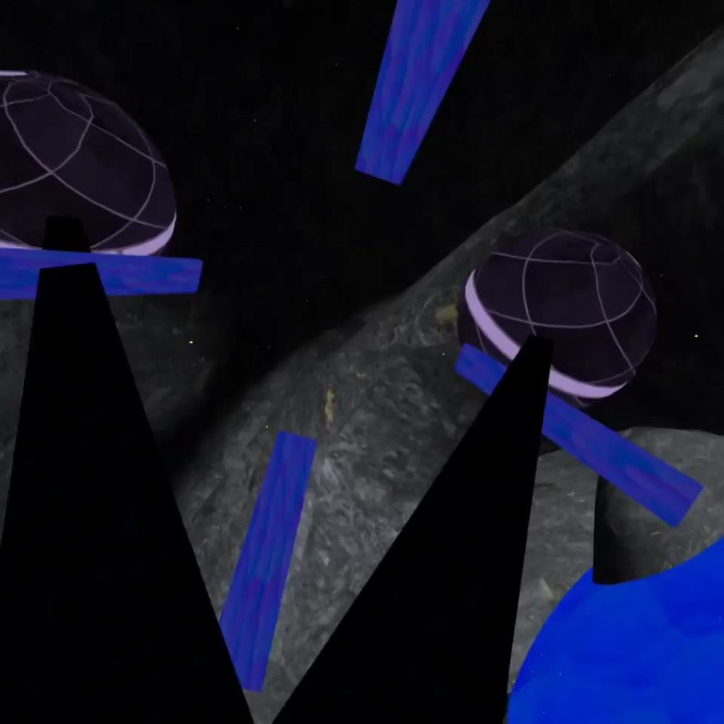
Hey, I think I need to texture the inside of this laser beam but I'm not sure how. Doesn't appear when you're inside of it which isn't what I want.

I've seen people say you've gotta use a shader but I have no idea what to do lol
Hey, i got a question.
why is the black fabric only shown from the outside?


everywhere else it looks like this
the geometry is one sided
unity will cull the backside unless explicitly told otherwise by the shader used on the material for that mesh
the better option is to have one mesh face for the outside and one for the inside
enable back face culling in your 3D software to see how it will be in unity
This effect requires a custom post processing step. In URP, that would be done either through the Post Processing Stack or as a custom renderer feature.
Thx. Did you know how to do that please ^^' ?


It's not something that can be easily explained to someone who is new to shaders and I don't have time to make it for you.
Ok fine no problem. Thank you so mush for your help ^^
Having trouble implementing a dissolve shader on an unlit material. The same shader works perfectly on a lit material, but on an unlit material it causes the transparent space around the sprite to become black when fully dissolved
Here's the relevant part. The 'split' is the main texture opacity.


whereas if I set the material to 'lit shader' it works fine and there's no black outside the sprite
(the glowing parts not being dissolved is a separate issue I haven't figured out yet)
Looks due to negative values. Try a Saturate node after the subtract. (It clamps between 0 and 1)
Yup, that worked! Thank you.
Oh, the reason why the glowing part isn't getting erased is because that part of the sprite is fully white, so step doesn't get rid of it. Any solution other than using an image editor to change it form white to one pixel off-white?
How does Graphics.Blit and such keep the ordering of operations intact?
After a lot of testing..
Now the objects and the player itself sort of float on top of the "cursed" plane.
Like 2 meters above them.
How can I fix that?
this is getting on my damn nerves now, can any one tell the difference between my code in the sticky note and the subshader setup in this image???
i get completely different results using my code setup versus the subshader but they look identical to me

seems equivalent to me. You sure your inputs are correct?
Turns out the solution was to saturate before AND after the subtract node
Anyway to use dotween on shader propterties, like colors or floats?
Figured it out. You have to do this:

how do you create custom SG nodes but not as in a custom code function - like an asset for the asset store
is it just subshaders at this point ?
Why are objects on my world bending shader floating like 2 meters above the plane, just following this video?: https://youtu.be/SOK3Ias5Nk0?t=405
Recreate Animal Crossing’s world bending shader in Unity.
In this shader graph tutorial, we will recreate the world bending shader (“rolling log” effect) from games like Animal Crossing and Subway Surfers.
🎁 FREE High-quality assets: http://bit.ly/2dhp-free-yt
🌎 Curved World shader asset: http://bit.ly/curved-world-shader-2021
📦 Download projec...
Hey, im using the URP Decal Shader for my project. i created a new material from the shader but unity doesnt seem to like it even though its the original decal shader. does someone know how to fix that?


Different techniques for rendering outline effects.
Thank you very mush ^^. However, I've got a problem : it's my first time writting shader code so I don't know how to implement it ^^'
How can I store the result for a fragment to be re-used between frames?
I've tried the following:
RWBuffer<float> buf1;
RWBuffer<float> buf2;

void Raymarch_float(...){
  if (t > 5) {
    Out = float4(buf1[0], buf2[0], 0, 0);
  }
  ...
  buf1[0] = someComputation1;
  buf2[0] = someComputation2;
}
But I'm obviously doing something wrong
(this is HLSL)
And I saw in the document that this type of render need performance. Or I made a VR environment where I activate the shader when my controller pass hover an object so is this dangerous to implement it ?
is this the correct way to clamp a texture in a compute shader??
{
    Filter = D3D11_FILTER_MIN_MAG_MIP_POINT;
    AddressU = D3DTADDRESS_CLAMP;
    AddressV = D3DTADDRESS_CLAMP;
    AddressW = D3DTADDRESS_CLAMP;

};
or am i missing something
tried simply typing "Clamp" too but idk. I haven't found a page that really explains the values to use nicely.
like there's this but very hard to decipher https://learn.microsoft.com/en-us/windows/win32/direct3d9/effect-states and this https://learn.microsoft.com/en-us/windows/win32/direct3d10/d3d10-effect-states
in a nutshell this is all i'm doing but it keeps wrapping a pixel.

https://docs.unity3d.com/Manual/SL-SamplerStates.html "inline sampler state" should work in compute too and save you a lot of headache. Like Clamp_Point_Sampler
ok ill try that thank you
but also does that mean i really only need one sampler?
if they all use the same settings
If you only need one type. I think so. There might more to it, but not that I'm aware
is the point of sampler_MainTex to inherit the settings of the maintex really?
cause if so that makes sense
but anyway ill try it
yeah, texure settings in the editor control the sampler that Unity will create
The doc explains it ok, basically some api let you separate textures and samplers
Yeah that seems to work. 👍
still losing a pixel at the bottom of my my sprite that uses an atlas however... not sure where in my math there that would originate.
Question/thoughts. I have an ocean surface, an sometimes some faces get rendered through the water, which is expected, but ugly. How would I go about discarding pixels that are behind the closest face of that surface ?
Not that it helps anyone but I'm pointing to the atlas (ex. x40 y40) but since we're starting at 0 with the id it's getting shifted one pixel to the left on the texture so the x and y of the rect needs to be adjusted +1. 👍
I have this code: materialNormal.SetFloat("_MagnetMask", magnetPercent); and it works, but the material is modified persistently
Should I create a new material runtime and work on it?
yes
you can also use MaterialPropertyBlocks if you want to make non persistent per-renderer changes
which one is better?
they do different things
I'm reading doc of materialpropertyblock
Note that this is not compatible with SRP Batcher. Using this in the Universal Render Pipeline (URP), High Definition Render Pipeline (HDRP) or a custom render pipeline based on the Scriptable Render Pipeline (SRP) will likely result in a drop in performance.
I'm using urp
so it's better for performance to create a new material in awake and use it
I have only one renderer with this material so I can use both solutions
am I wrong?
if you only have one renderer using it it's probably not a huge deal either way.
BTW if you use myRenderer.material that automatically creates a new material
Actually only if there's other renderers using the same mat 🤔
    private void Awake()
    {
[...]
        mRenderer.material = new Material(mRenderer.material);
    }
In my shader I want to update only certain pixels each frame, and re-use pixels that aren't updated. I'm using shader graph and an hlsl script and was wondering what the best way of accomplishing this would be? Is there a way to render the entire screen as a texture and use the previous frame's output as an input texture to shader graph? Or would that be too slow?
If you use a compute shader you can modify a texture as you wish (updating or not updating whichever pixels you want), then use that texture in your rendering shader.
If you want to use the entire screen output as a texture for a shader - that kinda sounds like PostProcessing
so maybe you're looking at making a custom post processing effect
Hmm, actually I guess I don’t need the entire screen, just the pixels of the object I’m rendering
What kind of effect would it be?
I’m trying to understand temporal reprojection but want to start with a really basic version first
I’m ray marching a volume and done some optimisations to get it down to 20ms but want to push it further by only raymarching partially and blending the results over multiple frames
(Or maybe I could do a high quality ray march for some pixels and a low quality one on others?) I would just need the pixel position (x,y) coords
recently upgraded to HDRP and ive had a slew of issues but this one makes the least sense. its only got 1 texture on the pink parts, and it has a texture but the pink makes it look like theres a 2nd texture missing underneath. it only does this on a few of the windows despite all windows sharing the same texture and model. very confused

magenta means you have a missing shader / material or a material using a shader that isn't compatible with HDRP
would underwater caustics be in the emission channel or the albedo channel
kind've confusing
hard to know what goes where
well yea but theres only one texture on there and that texture is fine with everything else
it's not the textures
it's the materials
oh just saw the tab on top. deleted extraneous material. thanks
where do I plug this

from what i can read online the paralax uv channel goes into the textures UV cordinates
and the depth offset can be enabled and connected on the master node
what's the master node
the one labeld "Fragment"
connected to the ao?
no to depth offset (you need to enable that first )
where do I enable it
looking for it rn

do I have to switch to HDRP?
not sure what renderpipline supports that
does it not show for you?
from what i can find at least at
Jan 2021 it seems that URP does not support it
and still not supported in 2022.2
nope
eh I guess I'll have to switch to hdrp
aaaand everything's pink
yeah it's too laggy
@knotty juniper what version of unity did you say supported pom on urp again?
"and still not supported in 2022.2"
aka not a thing in URP
that's the latest?
for most cases yes
how about realism
idk I'm not really sure what to do in unity anymore but I've always wanted to get really realistic water so
I'm doing that
¯_(ツ)_/¯
how did I scroll a texture again? @knotty juniper

this would use a signe singal to offset X any y of the cordinate
yes but instead of doing that it changes its color
tiling and offset only works with UV cordinates
you have to use the value in the texture sample node in the end
keep the UV inpuit to the tiling node empty or intput the UV 0
it's not a single texture it's 2 which I want to scroll in opposite directions
so which ones do I plug?
scroll them independent and then combine them after that
that's what I was trying to do
but the thing changed colors
I basically want them to be tiled automatically depending on the object's scale so I don't have to tweak it each time I change something
and at the same time move around
do I just tile the final moving result?
you could plug your tiling valus in tile offset node
it just kind of flashes

no no no
also why did the normals change color
I changed the texture type to normal map and now it's just a single color

because you are doing it wrong
well how do I do it right
istg this worked before for the other water shader what is going on now
now they're gone altogether


you dont its just so you can adjust it that just some demo values
correct
if you want to have control what axis it should scroll input a vector 2 into the multiply
then you can controll the speed and direction for each axis independently
the scale will make them be proportional to the size of the object right?

Ophélia are you writing an actual paragraph or something
I'd like to be able to represent a texture by values given from the user, could be either floats or integers...
not too sure how that would be done! I put something together real quick that does just that, check it here => https://github.com/OpheliaVRC/ShaderStuff/blob/main/TestShader4x4.shader;
I'd like to know how actually that would be done, a better approach, just anything different... like maybe provide a texture and then change each pixel of it to the new given values?
how would you go about it?
like
converting an image to numbers?
that's more than doable
almost, numbers to image yes
sure you can do set pixel via code
code! you mean C#?
correct
the thing is... I'm not allowed to use that...
it should all be part of the shader itself
then how are you setting the values to the shader/Material?
or better
what result do you want to have?

a full texture!
the user is gonna be able to provide the values from the shader GUI aka material in the Editor.
oh
like
you could color / modify a existing texture before displaying it in the shader with the values that the user gives you
but this will not make a new texture asset
you for some reason manually type in the values of an image
and use that
instead of painting it normally like any sane and normal person would
"Innovative"
how do I untile this

so it looks natural instead of this tiled abomination
istg like 80% of the reason stuff I make in unity looks bad is because, and solely because of tiling
limitations are the reason, I'm only allowed to provide the image values via the AnimatorController by making a bunch of AnimationClips and use the controller Parameters in something like a BlendTree to drive the shader values, which would be pre-animated.
something like this?
https://github.com/Unity-Technologies/TilingRandomization

GitHub
Randomized Tiling for Unity ShaderGraph. Contribute to Unity-Technologies/TilingRandomization development by creating an account on GitHub.
yes
there's also that it looks too flat and too shiny in some way
pom would've helped...
pom is the the solution for water vertex offset and normal should do it
ok
I'll try putting it into position
I can't plug it into position
why?
how do I plug it into position
it's okay, I'm fine with that! not interested in making a new asset, however!
will this also allow me to change the current texture's resolution?
and either way, how would I go about modifying each pixel of the texture?
so I'll just adapt everything to this

you cant change the texture at all you only can read the texture and combine them with the color values you have and then display them
so no texture resolution change
figure it out
or dont use it
check the example shader
as I said it doesn't work for my node setup
unless you can save the resulting normal into an animated texture
that just loops
I checked and it doesn't work for what I have
any alternatives?
ok got this, so since I can't change the resolution of an existing texture in a shader, I think the way I'm doing it currently is the way to go?
that's if you already checked it... I'm not too sure what's exactly happening, but the final result is exactly what I've been looking for, however,
due to my shaders lack of knowledge, I wasn't too sure if what I'm doing is even right to begin with, but it works!
with that said, should I stick with what I have, or could it be done in other better ways? limited to shaders
ok