#archived-shaders
1 messages · Page 21 of 1
one more thing....Does mesh colliders affect performance that noticeably?
i have trees and objects using mesh colliders of their own...
depends on the tricount
generation happens when it's loaded
but the collision test happens every frame that gets passed the broad phase collision test
yeah it's going to depends very heavily on how the broadphase goes
which depends on how your scene is set up
i didnt get it...
what's broadphase pass?
broadphase is the first phase of collision detection in which only AABBs (bounds) of colliders are checked. The collider shape itself doesn't matter at all in this phase, as only bounds are used.
therefore the actual collision shape math only happens if they are very close to other colliders
I say profiling is the first step in performance optimization and you're wasting your time if you don't profile
and for trees use capsule colliders unless you intend on climbing it
where does the profiler hint up about colliders?
if i make them get shot by bullets?
each hole decals should get attached properly isnt it?
i mean....in which section in the playerloop it is specified?
about colliders performance..
in that case try to use a lower detail mesh for your mesh colliders if you get bad perfs on multiple trees, but the issue is usually with rendering those trees, not the colliders for them
i used the mesh colliders of the low poly shaped version of the actual trees...
those are less than 1200 tris
i think it wont give any noticeable performance drop
As its for mobile...so im measuring everything inch by inch....srry guys for bothering
physics simulation
oh , thank u, thats what i needed to know
btw ,, what do u generally use for collider? mesh or primitives(box, capsule etc)?
I use the appropriate collider for the situation.
before i move on with my model i need to know, can i make eye tracking using shaders like the source engine in unity or should i put bones in the eyeball of char, cuz her eyes arent circles so i bone wouldnt look good
Is there an easy way to get a pixel's world space position in hlsl?
v2f vert (appdata v)
{
    ...
    o.world = mul(unity_ObjectToWorld, v.vertex);
}
I am doing this to try and get the world space, but this is just giving my 0 always
this looks good but it's also the vertex shader. You'll need to read the data back in the fragment shader (where it will have been interpolated per-fragment/pixel) to get the position of the individual pixel
            struct v2f
            {
                float4 world : WORLDSPACE;```
I have this in my fragment shader struct with a different semantic to note it, is that right?This answer uses the TEXCOORD0 semantic. I'm not sure if it matters:
http://answers.unity.com/answers/1272541/view.html
TEXCOORD0 is being used currently by the uvs, can TEXCOORD1 work?
I don't know enough about shaders to tell you 😛
try it
I don't know if semantics get "used" either
yes
I have shader and it is bugged if I swap platform to mobile - idk why, using unity 2020.3.41
it looks like this on mobile

meanwhile if I swap target platform to PC it works as desired:

im using URP
any idea why it is bugged when picking android target? or maybe I should ask in URP channel?
Unless it's a normap map you probably don't want the Type set to Normal on the texture sample. Perhaps different platforms use different normap map encodings idk.
i have no clue about shaders, i got this from 3d guy 😛

this is the file, i doubt this qualifies as normal map? 😛
No, change the Type on the sample node
I got 'implicit truncation of vector type' at this part of my shader... but ambient ouputs float[3] and saturation takes a float[3], so how can this happen?

Perhaps it lies in the code those nodes use? Could view the generated code to check. If it is that, it's not really fixable though. I guess could switch to a Custom Function, or just ignore the warning.
Very odd. I can't bother making a custom saturation node just to hide a warning though. Guess I'll leave it as is
anyone here know how to create saturn's rings in a procedural skybox?

with the shadows?
the seems overboard
yeah like i guess you could try with SDFs for spheres, but i wouldn't
you could use 2 meshes, one for the sphere and one for the ring, and polar coords should work for the sphere while the ring just has the uv wrapped in a way that it expands from the center, that or you could band the colors based on distance from the object center of the ring
just the rings, no shadows
without
well
faking it all on a skybox is of no advantage
but if you insist, use sdf for the sphere, sdf for the plane-aligned circle, mask out the center of the circle, figure out how to fill the colors for them (distance from center for the circle, distance from center y for the sphere, step the edges) and rotate them
you're looking into more trouble than needed
and if you want lighting, get the direction and color for the main directional light and blinn-phong shade
or any shading/lighting model you like
phong would probably get you the desired look better
but in all honesty, use real meshes
Sounds too complicated. I want the effect to be like you are a person on saturn, not that you can see saturn in the distance
I nearly got it by stretching a texture2d image across my skybox uv
considering this is what earth would look like with saturn's rings

you'd first correct the uvs, then it's just the matter of a stretching a texture across either the u or v of the uv
the way you'd unwrap your skybox uvs is to first get the world position, normalize, so you'd get a sphere
then arcsin(y) from the sphere normals we just got and divide by pi/2
and then arctan2 of the x and z component of the sphere normals and divide by 2pi
and then combine the two to get a final uv
with arcsin(y) being u and the result of the other being v
and then you'd just have to stretch the texture across y (confining it to a set width at x)
dont forget to lerp it with your skybox color
or other methods of blending if you like
ooh yeah i might try this on my own game too
thx, currently working on stuff in vfx graph but i will take a look at this later
if you have a plane and want to find the distance at which a ray from the camera intersects with it, you can calculate it as
distToPlane = dot(camera position, plane normal) / dot(view direction, plane normal) give or take a minus sign bc i never get those right
(Also add a check to make sure the result (properly signed) is not negative)
Then I would calculate the position of the point of intersection
pointOfIntersection = distToPlane * view direction + camera position
then the length of that vector is the radius out from the origin; if the origin is the center of the planet, then you just need to whack on some texture/noise/other function and give it length(pointOfIntersection).
You also get shadows relatively for free, since you can calculate step(planetRadius,length(cross(pointOfIntersection, sun direction))) and assuming the origin is the center of the planet, then this should be zero when the planet's in the way of the light, and 1 elsewhere; multiply by your noise(radius) from earlier and boom
(the planet will also be so large that you don't need to account for the player walking around; camera position will be a large constant/constantly rotating (if you want day/night) vector
Is there a reason why my blur shader flips the entire screen when I assign it to render after opaque?
Without seeing the shader it's hard to tell
Its not a graph anymore i turned it into compute, but what it does is basically getting 4 copies of whats behind and shifting each in 4 direction
No rotation
And why setting it to render after opaque flips it and nothing else is magical
Btw, anyone knows how to correctly pass per-instance data to an instanced shader? I am using Graphics.DrawMeshInstanced (because I'm on webgl) and using a MaterialPropertyBlock with SetVectorArray to send the data array, and in the shader using an array of float4 variable to get the data using instanceID
I am able to access the data, but there are some instances, where the data is totally incorrect, and seems like the instanceID does not reflect the order I passed the matrix array to the DrawMeshInstanced function
I think the opaque texture is flipped when the rendering starts
it gets unflipped somwhere in the graphics pipeline, check in RenderDoc
Thats interesting, probably the order of execution that went wrong, thanks!
As to why it's rendered flipped, I have absolutely no idea xD
probably a readback order something something optimization, lol
yea probably
❓ Just so it doesn't disappear ❓
not sure if that's a coincidence, but that's exactly what my current skybox UV is like, haha
one question though; how can I avoid having a sharp vertical line in the skybox? it's noticable in my clouds
this is the result but that vertical line is noticable

i thought about rotating the uv so the sharp line is on the horizontal orientation, but that's probably not the best fix
whoa... that is sharp
weren't expecting that?
i dont actually remember what mine looks like, i'll quickly open up the project
I can't figure out why, i might just remove the blur part and let it be a super cheap flip shader
The exact same implementation in shader graph doesn't have this issue
Wha
Seamless texture?
it's procedural and random, so no
seamless noise?
mine's the same 😆

i dont have any white lines though
neither do i, but my clouds do show that there's a seam in the uv there
yeah i think this wrapping method might not deal with uv seams the best
You could mirror it at some point, but that has its own issues
(you could try adding one set of clouds to another set but with UV.r -> 1-UV.r, that'll get rid of the line in theory)

GitHub
Adds various noise generation nodes to Unity Shader Graph, including 3D noise nodes. - GitHub - JimmyCushnie/Noisy-Nodes: Adds various noise generation nodes to Unity Shader Graph, including 3D noi...
Perlin noise 2D periodic
I'm guessing they are just using the noise node for clouds
here's my implementation if you're interested @tall girder

turns out uv0 uv coords work
wow thanks for sharing!
got an ingame screenshot? I'm super curious!

that's so cool! nice art style as well
yeah... i think the sun is a bit out of place
you're using arccosine to create a sun too?
hahaha yea xD
the only good procedural skybox tutorial imho
@full zephyr could you show me what your property values are set to? I can't seem to create the ring
check your tint alpha
what should it be? changing it seems to make no difference still

ahh there she is
@full zephyr made a slight modification to avoid the texture getting tiled.

thank you so much for this, I am super happy about the result!
yeah i didnt notice it was tiled
Any help with this still appreciated 🥹
Trees with alpha textures seem to have some sort of z clipping issue. Anyone know how to fix this?

URP Lit shader, with transparent surface type
I got these bugs when upgrade from unity 2021 -> 2022, does anyone know how to fix it?

- upgrade all your packages to the latest version(s)
- delete your library folder
- restat Unity
not necessarily in that order
thank you! I will try it, but I event got it when I create a new 2022 project form URP 3D template
I still got it, I am try ign to use URP 12.1.7 instead
set the material to alpha clip or cutout instead of transparent
Oh didn't notice those were bugs i thought its just smaller leaves, and looked pretty nice
Static image
took me a second too
I think I have an idea
I'll just encode the data into the transformation matrix itself, I don't need object size anyways lol
Sweet that does the trick
how can i change the shader so the 2d things are affected by the 3d lights?

the options to change it are hidden

Hey folks. this is a shader issue right? I'm importing a glb. Not sure what I'm missing.

guys
is Src Alpha One better than Alpha Blend? incase of performance?
else Alpha Test, What could be the fastest alpha in the second position?
It means that the shader is incompatible/broken.
I'm new to shaders... where is a good place to start learning how to trouble shoot something like this?
are you actually using a custom shader?
you can just replace the shader with another one on the material of the object, if you don't use a fancypants custom shader
if you want to create custom shaders, check out shader graph to start out
If there is a difference, you could find it using RenderDoc. Spam like 200 fullscreen transparent planes in the scene and check performance
But isn't it just all the same? I mean alpha blending is something the hardware does and not scriptable, no?
Or could we change it, just not in unity's shaders?
Hi,
How can I transform from world space to screen space in shader graph? There is no Screen Space matrix, only View space. Basically I need to go from Position (Absolute World) to same result as Screen Position (Centered).
Or maybe do a projection fix for View Space position to make a Screen Space.
Pink just means shader error
Most likely the objects have materials with shaders that are missing or are incompatible with your render pipeline
All alpha blending is mostly the same, I believe
The calculations could be different but probably not more than marginally
The big cost is the transparency itself
You'd probably transform to non-absolute World space first (not sure, I don't do HDRP).
Would then Multiply using the ViewProjection from the Transformation Matrix node - matrix in A port, and Vector4 node in B port with XYZ set to your world coord, W component set to 1 for point or 0 for direction.
Then Split and Divide itself by the A output.
No custom shaders. I new to shaders an all this so I'm not sure what to do. I was missing with changing the shader some, but it nothing worked.
Hello, i'm using this to make a texture scroll, how can i change the direction of the scrolling ?

Hey! I have an issue with using the _CameraOpaqueTexture in VR.
When I playtest without VR it works just fine, but when I'm in VR, it won't create the texture for it. Figured this out using the frame debugger.
In VR it's just the unity default texture.
Put your Multiply into one of the axis of a Vector2 node before putting it into the Offset port. That way you can control the X and Y separately to scroll only on one axis. Negate to scroll in opposite direction.
For more complicated angles might be able to use Rotate node somewhere.
Thanks that's what i were looking for ! Dont know why I did not though about vector 2 lol
Assuming URP, I'd make sure if you have multiple URP assets per quality level, the Opaque Texture is enabled on all of them. I'd probably also check there's a CopyColorPass being executed in the Frame Debugger.
For Single-Pass Instanced mode I'd make sure you are using DeclareOpaqueTexture.hlsl, so you take stereo stuff into account properly : https://github.com/Unity-Technologies/Graphics/blob/master/Packages/com.unity.render-pipelines.universal/ShaderLibrary/DeclareOpaqueTexture.hlsl
I'm using a shader graph, I don't know if I can use DeclareOpaqueTexture with that.
Checking the frame debugger right now.
Ah okay, it would already be using DeclareOpaqueTexture then
Checked the frame debugger, this is how it looks:

I should mention I'm using only one URP asset.
hey, does anyone know how i can make a 2d sprite be affected by 3d light?
the way i have it set up now looks okay in the editor but not in game, it goes black and when when the sprite flips it disappears

can i have some help please?
as soon as i move it turns black

and if it faces the other way it disappears
Don't expect 2D sprites to be lit correctly by 3D lights
I'd say just use 3D geometry instead for that
how would i do that?
use 3d geometry I mean
because it's meant to be a 2d game with like 3d level geometry
Use the sprite texture on a 3D plane.
would that still work with animations and like hit boxes and stuff?
Not the same way as with sprites, no
I don't know why there's no support for using sprites in 3D space with 3D lighting and sorting, even though they're procedural 3D meshes
This is the frame debugger, do you have any clue why it won't work?

I saw there was a way if you coded a shader yourself or something
there was a way to make a sprite react to light
There's a CopyColor, so afaik it should work
how can i make a inverted fresnel effect, but in screen space? i want it to look flat and not 3d.
feed screen space position into a fresnel node, and invert it.
why is there no alpha available here?

you need to change your graph type to be transparent
i want to link the alpha of the texture into the output
how do i do this?
would that replace the normal or view dir?
for view dir I think it'd always be (0, 0, 1)
for normal, you'd have to create sort of generate a spherical pattern of normals (if that's what you want) although really the normals are up to you
depending on what shape you wish the fresnel to take
oh so i could just use the mesh normals then?
uh you could but you'd need to convert them to screen space I think
ok, ill try that first then
how come it works fine when i first start the game and dont move at all, but as soon as i move this happens?


it just removes all the textures and leaves the basic shape
idk what to do
im not sure why this happens
this is what happens how i fix
how can i blur a solid color?
like lets say i have a toon shader and im using step. how can i blur the edje to make it smooth?
You don't practically blur things
It'd be better to not let the toon shader create the hard edge in the first place
how would i go about doing that then?
@gloomy gust No crossposting please.
Hi evryone!! I would like to learn how to write shaders for Unity. I have seen that there are many themed books online and I find very basic videos on youtube. Would it be worth buying a book online? If so, which one?
How do I go about using scene/world depth to the screenposition node? I'd like to just use the x/y screen positional coordinates from the node, but I'm not too sure what other nodes I should be combining with it. There is a scene depth node, but even experimenting with it, there's not been much change to the outcomes.
This feels illegal, but free data for instanced rendering

Then like the others said just pick the standard shader of whatever render pipeline you're using
Ah thanks. I figured it out. I didn't load in the correct openbrush SDK.
Alright, so I messed around with the stuff today and came upon the screen position node. So, by using the aspect ratio and the screen position node you ignore the UVs of the quad and instead just use the exact values you set it as. There is a problem with depth with it, which isn't much of a problem with a UI, but world space does not apply to it, so the texture will always remain the same when you zoom in or out.
The node is actually pretty damn cool alone. Totally going to make some vfx with it.
Is it possible to make shader that chooses random color in specified range? I want to create glowing material for particle system using URP
May not even need a shader for this. If it's for the Particle System component (Shuriken) you can change it's Start Color to be based on a Gradient. When particles are spawned it'll sample a random position in that gradient.
Though you may need a shader to boost it's intensity (e.g. Vertex Color node multiplied by a float property), if you want it to glow with Bloom post-processing
yeah, i know about the option to choose between starting color in particle system, but when i add glowing material to it, it's color overrider partcile system options about starting color
You need to use a shader that supports Vertex Color. (Vertex Color node in shadergraph, or : COLOR semantic in vertex input struct in HLSL)
gonna try it, thanks
i totally didnt get what you said hahahaha
i came up with this

tiling always have to be less than 1 so i had to choose do i lower x or y value
but took aspect ratio of overlay texture and sprite texture, then divided them
based if sprite texture has bigger or lower aspect i feed 1 to x or y and feed division to other
works no matter the aspect of overlay texture and aspect of sprite texture

for some reason i can run along the y axis and it works fine
but as soon as i run along the x axis, it breaks


this is the full shader btw
i feel like im so clooooose
flipping the sprite yeah
the y axis works well
but the x axis makes it break to that weird gray thing
even without that normal bit, that issue still arrives
How are you flipping it? Rotation? renderer flipping? scaling?
Remember that sprites have fucked up tangents so messing with their normals can be tricky.
i am flipping it via scaling
it goes from 1 to -1
and also even id i odnt flip it this issue happsn
Does anyone know why my shader graph is pink?

excuse the awful framerate but this is what it looks like
Nevermind I figured it out
What is the best way to access the mesh velocity within a ray tracing shader? I'm using srp and reading MaterialPropertyBlock documentation i found that it "will likely result in a drop in performance."
This might be just a lame question but... Its possible by any means to "duplicate" a mesh with a Shader? I mean, like... "tilling" a complete geometry with its vertices and the UV and everything.
The output would be: I have one game object with a sphere mesh with red as a base color, after the shading its applied I get x amount of spheres of the same characteristics drawn on screen.
pass the velocity into the shader each frame as a Vector3
oh wait for a raytracer? No idea
Is the light behind the sprite?
spotlight is in front of it

idk why its invisible but
I guess with GPU instancing right?
any it happens with other light types too?
yeah
i think im just gonna make my game 2d i cant lie
That's likely for the best
You'll have the option of 2D lighting in that case still
its a shame but like
its whatever
can i have like
3d stuff in the background of a 2d game?
like not interacting with the player or anything but just as aesthetic

Arigatou :3
Sure, why not?
im switching to 2D URP for ease of use and i was just wondering if it was still possible to light 3d shapes
Aah, that probably not. Renderer defines how rendering in your scene works.
You could fake 2d lights with a 3d renderer to a degree. But you can't fake 3d with 2d renderer. You could probably write your own renderer too, that would combine both, but I imagine it's not so simple.
i tried doing that with my sprites and it didnt work
so im just not gonna bother
im sure i can make it looks nice with 2d anyway
@compact reef hey. Please avoid unsolicited DMs. They're against the server rules. You can ask your question here and I'm sure someone will answer.
the issue may exist here for long term...thats why i didnt want to burden here..
whatever
If you have a long term question, you could open a thread.

does anyone know the fix?
if you are using raytraced subsurface scattering it causes dark lines to appear where your original geometry is
basically tessellation and raytracing subsurface dont seem to work together
is this a bug or am i missing a override or something


dual lobe looks pretty poggers without raytracing
but i want raytraced subsurface :L
hi guys! wanted to know what are the best places to learn shaders?
Brackeys has lots of good videos, there also are tutorials on how to do various effects on Catlike Coding
Really depends what you want to learn though
cool what would be the best place to start?
I would recommend starting with shader graph (if you haven't used it already); you can get a lot done and it streamlines the process since you don't have to worry about keywords and syntax nearly as much
awesome, thank you @karmic hatch
I'm a little bit confused, I want to create a shader that i can give 2 Colors, and on command by changing a boolean, it lerps from one color to the other. Basically an on-command color swap. I want to be able to put this on multiple objects.
First of all I'm struggling because I don't want to specify a texture in the shader graph. I want it to take the sprite texture that i already have in the sprite renderer. Also every time i switch between colors, it does not tint the sprite, it fills out the entire sprite renderer area
Maybe I'll just make a script instead, that has a function that lerps the colors, and has direct access to the Color value of the sprite renderer
You can create a texture property that can then be accessed in the material inspector or through a script.
Also if you just output a color to the base color of the shader, it'll paint the whole sprite renderer area that color; i believe that's working as expected. You want to instead blend the texture color with the new color; perhaps through multiplying or fading.
Is there a way to get an objects texture without explicitly giving it a texture as a property?
if you understand what i mean
Can use the _MainTex reference. The SpriteRenderer passes the texture into that.
Hi, does anyone know why using shaders deforms my sprite? I created a simple setup, but when sprite appears, it's all blocky and weird. I was following Brackeys tutorial about making glow, and i already added emission map to my sprite atlas.

in game it looks like this, earlier it was normal circle

You need to connect the texture's alpha (A output) to the Alpha port in the master stack. Though currently you don't have that block listed in the Fragment. If it's a sprite you should be using the Lit/Unlit Sprite Graph type. Can change it in the Graph Settings.
Thanks, works like a charm now
Hey can anyone help me with a shader issue please?
I had a CG shader which worked without URP. So i converted it to HLSL but it still doesn't seem to work. Does anyone see the fault in my conversion? i have attached the CGShader and HLSL code I used this guide: https://teodutra.com/unity/shaders/urp/graphics/2020/05/18/From-Built-in-to-URP/
Thank you


Teo Dutra's portfolio
Nevermind fixed it forgot tag on subshader
and lightmode should be UniversalForward

for lighting should i clamp the dot product to 0,1 or add 1 and divide by 2 to get 0-1 value range
both get the same result but with one of them 0 becomes 0.5, and with the other one 0 becomes 0
which one of them is generally used
grab a garbo phone and try it out
I know this is probably a very stupid question, but someone said this in a youtube comment. And i guess this is the vert but i don't really know...
Does anyone know how to do this.
I'm very new to shading so yeah


This is the entire script: https://paste.ofcode.org/y5jvjwZSFJ9hCNuGTFhzvL
This is the yt video: https://www.youtube.com/watch?v=oC471v_2jC0
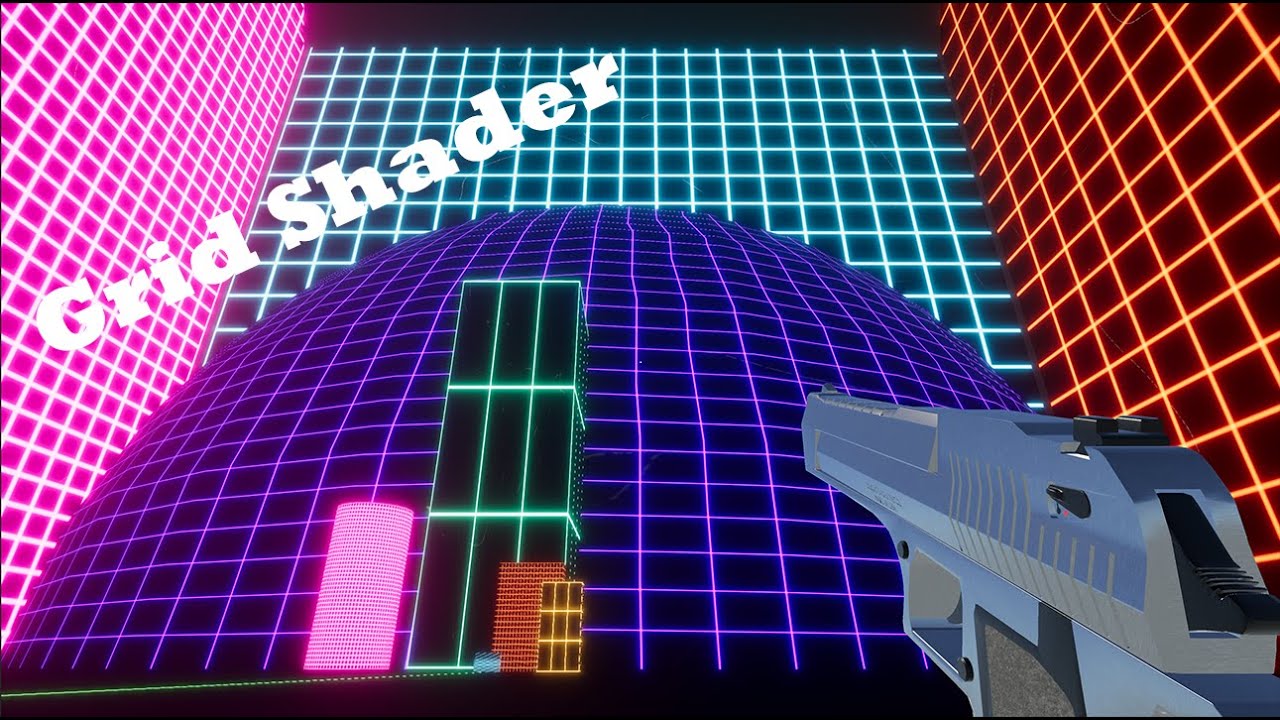
#Unity3d #GameDev
I am having a lot of fun learning how to write shaders in Unity. A while ago, I was working on a city builder game, but stopped when I couldn’t figure out how to draw a grid over a selected tile. Since then, I have looked briefly at shaders but always felt like they were difficult to learn, and there were not many detailed guid...
when using AppendStructuredBuffers, why does it matter what count i set?
is it a maximum?
the logic is unclear to me
is it constant size and just keeps an internal memo of which index to put objects on, so to speak?
and besides, what if i have a buffer for say 512 bytes but only get results worth 256 bytes
It needs to know how much memory to allocate
so i take it its just a maximum
Yes
makes sense
Does the shader work? If not, what does its output look like?
the shader works, i just can't change the color of the "non-lines"
I don't think you need to touch the vertex color since it doesn't seem to factor in anywhere else?
But how do i change the background color of the grid then?
If you add a texture, that would do it, or if you change the fixed4 gridColour = (_GridColour * GridTest(i.uv)) + tex2D(_MainTex, i.uv); line to read fixed4 gridColour = lerp(_GridColour, _NonGridColour, GridTest(i.uv)); and added another property for _NonGridColour
(if you do the latter, you can remove _MainTex)
Thanks! New problem: I have this block, but the grid is not squared, how can i get the grid squared on every dimensions (square cube, rectangular cube)?

If it's always going to be in that orientation, you can use world space coordinates to sample the grid.
Also I would recommend instead of the loop in GridTest, replace it with
float GridTest(float2 r)
{
  float result = 1 - smoothstep(0.0, _GridLineThickness,abs(0.5 - fract(r.x)));
  result      += 1 - smoothstep(0.0, _GridLineThickness,abs(0.5 - fract(r.y)));
  return result;
}
I think it would be quicker.
I have a new grid script now
bc the other one looked bad
the lines weren't sharp
I just don't understand why it's so hard to create a simple grid shader for a cube in whatever dimensnion
Ah that's easy; where it has smoothstep, you can swap that for whatever you like. You can swap it for step(abs(0.5 - fract(r.y)), _GridLineThickness) for example
The UVs don't know about scaling
yeah but that doesn't fix my problem
yeah i know
but how can i make this work then?
If you replace the UVs with world space coordinates (or object space coordinates multiplied by the object scale vector) then you can create a 3D grid that will be invariant when you scale the object
as i've said, i'm unfortunately new to these grid shaders
This is my new grid: https://paste.ofcode.org/KkBEeXSbK9yyQnV2cjhgiw
also from a tutorial
can you please explain
or send me some code?
float3 worldScale = float3(
    length(float3(unity_ObjectToWorld[0].x, unity_ObjectToWorld[1].x, unity_ObjectToWorld[2].x)), // scale x axis
    length(float3(unity_ObjectToWorld[0].y, unity_ObjectToWorld[1].y, unity_ObjectToWorld[2].y)), // scale y axis
    length(float3(unity_ObjectToWorld[0].z, unity_ObjectToWorld[1].z, unity_ObjectToWorld[2].z))  // scale z axis
    ); // Found on the forum (https://forum.unity.com/threads/can-i-get-the-scale-in-the-transform-of-the-object-i-attach-a-shader-to-if-so-how.418345/)
float3 objectPosition = o.position; // you will need to tell it to store the object space vertex position

objectPosition *= worldScale;

float lineStrength = min(1, step(abs(0.5 - fract(objectPosition.x)), _GridLineThickness)) +
                            step(abs(0.5 - fract(objectPosition.y)), _GridLineThickness)) +
                            step(abs(0.5 - fract(objectPosition.z)), _GridLineThickness)));
this should work (though as i mention in a comment there you will need to tell it that you want the object space vertex position and store it in o.position)
might I recommend using shader graph? it makes things a lot easier and more user friendly
where do i place this code
oh lol nvm
the () give me errors

i removed them
yep my mistake
another error 😦

oh sorry, i didn't read your comments
i'm so sorry my bad
uhm
@karmic hatch Can you explain perhaps how i can make the code work and remove the error?
i think in the struct Input {} you want to add a line
float3 worldPos
and then swap objectPosition = o.position for objectPosition = mul(unity_ObjectToWorld, IN.position.xyz).xyz;
hopefully that will work
now it doesn't because objectPosition isn't declared
where should i declare it
when you give it its value
float3 objectPosition = mul(unity_ObjectToWorld, IN.position.xyz).xyz;


nope
frac maybe?
in glsl it's fract, that's what i'm more used to
yeah it's frac in hlsl


yeah frac worked
oh frac has to go everywhere?
it only worked to desolve that one error
yeah fract is what it's called in glsl, frac is the hlsl version
i still get these errors
so anywhere there's fract, replace it with frac
i still get other errors
there should be one close bracket at the end of the first line, then two on the last line here
the step()s should be adding
as for why it's mad about _GridLineThickness, idk - that is what you called that property, right? (or did i misremember something)
yeah np i fixed that, it was called linesize
no errors now
woo!

you did copy over the whole float3 worldScale thing?
yes
rather than unity_ObjectToWorld, i think it should be unity_WorldToObject
everywhere?
?
it's not working bro
just in line 105 sorry
bc it's already in world space so we want it in object space, not the other way aorund
once it's in object space, we multiply (or maybe we should divide?) by the scaling and it should have the same scaling as world space, but aligned to the object

dividing also doesn't work
wowowow bro, where does your code even link with the existing code?
- get the object space -> world space scaling
- get the object space positions (yellow highlights: swap unity_ObjectToWorld to unity_WorldToObject, remove that .xyz (i had gotten confused))
- multiply the object space positions by the object to world scaling, so now the scaling is uniform with world space scaling

which xyz should i remove
the first one, highlighted yellow
the thing that i find weird, is that you're not using the lineStrength anywhere
the .xyz makes it be treated as a direction and not get translated but we do want it to be translated back to the origin bc the world space position is not near the origin
wait
lineStrength is 1 when it's a line, and 0 otherwise

yes replace whatever there is deciding where to draw lines, with lineStrength
easier said than done
Any ideas why this scrolling UI shader breaks when in the actual game but not otherwise?
Using URP and scrolling in shadergraph using time node. "Image" UI component.
GIF 1: Playing in editor, not what I want
GIF 2: Prefab editing, what I want
https://gyazo.com/1b28d7a525bb91d54ac99da97d064317
https://gyazo.com/e31f1ad245415d2ac91d0a4682dc448c


how
cut this and paste it below the lineStrength definition

and then remove this: and replace it with brightness = lerp(brightness, _LineColor.w, lineStrength); color = lerp(color, _LineColor, lineStrength);

            //This checks that the cell is currently selected if the Select Cell slider is set to 1 ( True )
            if (round(_SelectCell) == 1.0 && id.x == _SelectedCellX && id.y == _SelectedCellY)
            {
                brightness = _SelectedColor.w;
                color = _SelectedColor;
            }

            if (frac(uv.x*gsize) <= _LineSize || frac(uv.y*gsize) <= _LineSize)
            {
                brightness = _LineColor.w;
                color = _LineColor;
            }


            //Clip transparent spots using alpha cutout
            if (brightness == 0.0) {
                clip(c.a - 1.0);
            }
cut this^ and paste it below float lineStrength = ...
and then replace
if (frac(uv.x*gsize) <= _LineSize || frac(uv.y*gsize) <= _LineSize)
{
    brightness = _LineColor.w;
    color = _LineColor;
}
with
brightness = lerp(brightness, _LineColor.w, lineStrength);
color = lerp(color, _LineColor, lineStrength);
i finally got results now
they're a good sign
bc they show some form of squares

            float lineStrength = min(1, step(abs(0.5 - frac(objectPosition.x)), _LineSize)) +
                step(abs(0.5 - frac(objectPosition.y)), _LineSize) +
                step(abs(0.5 - frac(objectPosition.z)), _LineSize);
here, replace it with
            float lineStrength = min(1, step(abs(0.5 - frac(objectPosition.x)), _LineSize) +
                step(abs(0.5 - frac(objectPosition.y)), _LineSize) +
                step(abs(0.5 - frac(objectPosition.z)), _LineSize));
nope

@karmic hatch ??
What does the result look like?
same

if you swap the brightness and color in the lerp()s with _CellColor.w and CellColor respectively?
(i.e. make lineStrength the only deciding factor in theory)
now i get something weird idk

what happens when you stretch it?
no diff
I am so upset why is there no way to fix this issue in Unity?

All i want is for it to blend all my ui images as one
I searched and searched and no solutions i tried work
huh so that would suggest worldScale is (1,1,1)... which it really shouldn't be...

this was what you meant right?
yes

use shaders
It should be rescaling from object space units (which aren't uniform in world space) to world space units
It's not actually moving anything around
if you have any idea how to fix it, let me know please
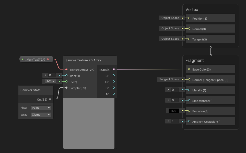
hey, I'm trying to replace my texture atlases with a Texture2DArray.
I've created 2 separate shaders, 1st from following a tutorial and the 2nd, I copied directly what was posted by another user.
In both instances, the mesh remains purpleish/pinkish
The script from the 2nd attempt is 6 post down
https://forum.unity.com/threads/solved-texture2darray-shader.713225/
Unity Forum
I'm trying to use Texture2DArray in place of a texture atlas. The problem is the Standard shader doesn't support Texture2DArray and I'm terrible at...
if anyone can help me / point me in the right direction, I'd be greatful
Purple with shaders means that it's either broken or incompatible with the tender pipeline. I'd check if the shader is meant for your current render pipeline and has any compile errors(select the shader asset and look at the inspector).
no complies errors
Can you take a screenshot of the shader asset inspector?
The shader in the post is for BIRP, btw. If you're using URP or HDRP, it wouldn't work.
ahh I see, SRP Batcher : not compatible
ok, you're right then
sorry to bother, one more thing if you don't mind
Can you tell me what my options are?
Achieving this functionality should still be possible in URP right?
Sure. You could make changes to the shader so that it works with urp, although that might not be easy. Otherwise write it from scratch or create in a shader graph.
Looks pretty simple to recreate in a shader graph imho
I'm pretty new to anything shader related but I should be able to slowly muddle my way through it I think
thanks for the help, I'd have been banging my head trying to get that thing to work for atleast a couple hours more
Got it -.- ..will leave this here incase someone as hopeless as me comes along
Texture2DArray
https://i.imgur.com/dWKFTUu.png
Are u online
I want to fix my problem
how exactly would I go on about adding an emission and an emission value on this shader? is anyone able to do it for me?
@karmic hatch are u online?
Hey, does anyone know how I can get the previous MVP matrix for every vertex (either in the shader itself or in the c# script so I can pass it into the shader)? I am trying to calculate the velocity of every point on the screen between two frames, so I need to know the previous position and thus the previous matrix.
use _CameraMotionVectorsTexture instead
I have tried that but I couldn't get it to work (it's always grey). In my script I do set cam.depthTextureMode = cam.depthTextureMode | DepthTextureMode.Depth | DepthTextureMode.MotionVectors; so I do not see why it isn't working so I thought calculating it myself might be easier (it isn't)
try disabling ssao
I am using the Built-In pipeline and not HDRP (from what I have read that is an option for HDRP). But thank you for the help (:
yeah... sorry i have no experience with how the postprocessing pipeline for BiRP works
That is alright, I still appreciate a lot you wanting to help me
You've read this, yes?
https://docs.unity3d.com/ScriptReference/DepthTextureMode.MotionVectors.html
So the motion vectors are in screen space.
It is intended for things like post processing.
Your target hardware has to support RGHalf data type.
What do you want to do? Do you want the previous 3D world space positions? Is screen-space 2D delta-motion OK for you?
Also check https://docs.unity3d.com/ScriptReference/Renderer-motionVectorGenerationMode.html and see the "see also" section links.
My main recommendation would be to make it in shader graph instead of writing the code. If it were something very complicated or involving complicated geometry it'd be better to write code, but it's simple enough that shader graph is better suited
I have it installed
Do u know how I can make a grid with it
?
You just need to implement the same/equivalent algorithm.
I'll try to make something in shader graph rn and I'll send a pic
Yes I have and SystemInfo.supportsMotionVectors does return true for my system. I am trying to do some motion blur effect (produced by the motion of the camera and by the motion of moving objects themselves), so I think 2d Delta-motion is what I want (I would have converted the 3d world motion into the 2d screen motion if I would have found a way to get the previous 3d world coordinate)

it's always a square grid, but modifying it to be different along each axis is fairly trivial.
OK, so it is the motion vectors texture you want. No idea why it isn't working for you.

remove the active target there and then add a new active target
it's for a different version of the render pipeline but afaik nothing in the actual graph should need changing
built-in or universal
whichever you're using
ig built-in
i added it to a material

but it
is not rendering
although in the grid window i see some blue

i'm using a 3d template from unity, which one should i choose then?
did you save the asset?
yay
Ok, but thanks anyway
new problem:

when i use a rounded block, it's completely messed up
Ah
Remove the bit where it does the cross product between position and normal
Just skip the cross product
this

yes just take the output of the multiply and go straight into the divide
like this?

yes that should do it
omg nice
at some cube sizes one or more faces might be entirely line color; that's what the cross product prevents. But if the normal isn't aligned along the axes it's going to act up

np :)
Hi, I cant get transparency to work in a Windows Build! I tried doing this https://answers.unity.com/questions/1403086/transparency-not-working-in-windows-build.html but it does not work for me.


Unity is the ultimate game development platform. Use Unity to build high-quality 3D and 2D games, deploy them across mobile, desktop, VR/AR, consoles or the Web, and connect with loyal and enthusiastic players and customers.
I have no idea why, but it seems to work now! Do you by any chance know where I can find some documentation for _CameraMotionVectorsTexture? (So I can for example look up what value range I can get) For a lot of the things I can access within my shader I haven't found documentation and only saw people using it
Hey, so I have a pretty basic stencil/stencil id shaders and I would like to ONLY DRAW what's referenced by the stencil and nothing else, when you're looking through it. Is that possible without too much performance overhead?
Maybe there's already something doable with those settings?


The alternative I can think of is camera texture based portals but that seems expensive..
I cant quite figure out how to add emission to this shader, if anyone can help me with that
Will a ternary operator in shader code cause branching, Unity I think uses HLSL which leads me to believe it wont if I understand correctly but not sure?
According to this, no; both sides are evaluated and then whichever isn't used is discarded.

Stack Overflow
I'm working on a vertex shader in which I want to conditionally drop some vertices:
float visible = texture(VisibleTexture, index).x;
if (visible > threshold)
gl_Vertex.z = 9999; // send ou...
Can anyone help me? i've got an issue where i made a shader in builtin lit shader graph but when i make it into a material its just plain grey (its a 3d object)
in the preview it has this small animation but as soon as i make it into a material it just turns grey.
Ive been in pain for 2 hours trying to figure it out. And when i made it into URP it just turned pink and didnt let me upgrade
whats the shader look like
(I mean the graph)
not the grey object I can imagine
I got no clue how... But it works... I just copied the whole thing again. Not even rewrote just copied. And saved. And magic, It worked. Im so mad rn at myself!!!
I my guess is you accidentally made an unlit graph, or just using an unstable shader graph version
All I know is that it is in -1 to 1 uv space (x, and y of course 2D).
When sampling from this texture motion from the encoded pixel is returned in a range of –1..1. This will be the UV offset from the last frame to the current frame. ```
From here: https://docs.unity3d.com/2021.1/Documentation/Manual/SL-CameraDepthTexture.html

Now how much that is in world space would depend on the depth value also, since further away items would be moving "more" than close-up items in world-space for the same amount of uv change.   Due to perspective.
But in 2d space, it's all relative to either A) the screen aspect ratio/orientation and/or B) the amount of space you'd somehow decide the camera frustum is covering as some average point???? Thinking about how much, say, 0.15 uv change in x would be if you were on a 1920x1080 monitor vs some mobile device in portrait orientation. Hence aspect ratio and distance in ws maybe factored in somehow.hey, i was working on a raytracer compute shader and when projecting a skybox it doesn't seem to wokr


this is what is being rendered. and the next photo is what should be rendered
You sure the color is supposed to be black and radius is supposed to be 1?
Well, then you'll have to share more details.
basically for every pixel on the screen i cast a ray, then if it misses i want to convert a spherical position(the direction i missed in) to a uv texture cord. then set that to the output color
just a basic skybox. the code i am using for this conversion is this
float theta = acos(ray.direction.y) / -PI;
float phi = atan2(ray.direction.x, -ray.direction.z) / -PI * 0.5f;
return _SkyboxTexture.SampleLevel(sampler_SkyboxTexture, float2(phi, theta), 0).xyz;
but it doesn't work properly
Where do you set the ray data?
And how do you render it? Blit?
Share the C# side too then.
It's the project that's broken. I messed with signed of the projection and got a half of the skyb9x
Box
K
The projection is broken?
Yeah projecting from direction vector to uv cord
Acos(ray.direction.y) /-pi to
Acos(ray.direction.y) / pi makes half the sky box work
Flipping other signs flips the x, y and side that is broken
public ComputeShader RayTracingShader;
public Texture SkyboxTexture;
public Light DirectionalLight;
private void SetShaderParameters()
{
RayTracingShader.SetTexture(0, "_SkyboxTexture", SkyboxTexture);
RayTracingShader.SetMatrix("_CameraToWorld", _camera.cameraToWorldMatrix);
RayTracingShader.SetMatrix("_CameraInverseProjection", _camera.projectionMatrix.inverse);
RayTracingShader.SetVector("_PixelOffset", new Vector2(Random.value, Random.value));
    Vector3 l = DirectionalLight.transform.forward;
    RayTracingShader.SetVector("_DirectionalLight", new Vector4(l.x, l.y, l.z, DirectionalLight.intensity));

    if (_sphereBuffer != null)
        RayTracingShader.SetBuffer(0, "_Spheres", _sphereBuffer);
}
private void Render(RenderTexture destination)
{
// Make sure we have a current render target
InitRenderTexture();
    // Set the target and dispatch the compute shader
    RayTracingShader.SetTexture(0, "Result", _target);
    int threadGroupsX = Mathf.CeilToInt(Screen.width / 8.0f);
    int threadGroupsY = Mathf.CeilToInt(Screen.height / 8.0f);
    RayTracingShader.Dispatch(0, threadGroupsX, threadGroupsY, 1);

    // Blit the result texture to the screen
    if (_addMaterial == null)
        _addMaterial = new Material(Shader.Find("Hidden/AddShader"));
    _addMaterial.SetFloat("_Sample", _currentSample);
    Graphics.Blit(_target, destination, _addMaterial);
    _currentSample++;
}

private void OnRenderImage(RenderTexture source, RenderTexture destination)
{
    SetShaderParameters();
    Render(destination);
}
i couldn't include the whole script because discord, but i put everything of substance
i think its very unlikely to be c# problem because the texture is being red properly.
You should link to it via a paste site as per #854851968446365696
Yeah I forgot about those
Hi, I assume this is a shader thing, but how would I go about projecting a target indicator onto terrain?
Similar to WoW AoE spell indicators, Moba target indicators, etc.
I can see I can use a shader to definitely do one target indicator based on an input, but what would I do if I wanted to draw any amount if target indicators at once on the terrain? e.g. if a boss had move telegraphs, his minions have them you have them allies have them.. and these indicators are on the terrain, on loose 3d models on the terrain etc.
Look up decals. Each rendering pipeline has different types though.
Well, different ways they are rendered.
Cheers, I'll look into them. Had no idea what to even be searching for 🙂
Looks to be exactly what I'm after, thank you
Follow up, any idea how I'd have a decal ignore certain surfaces? (in this case, I wouldn't want them to draw on my characters). I'll be looking at more tutorials tomorrow, but figured it's worth asking before I head off for the night, just in case it's an easy answer 😛
Depends. You on urp?
I am (just looking around for decal layers atm)
Oh, I wonder if those are in yet. Otherwise you'd have to fool around with some renderer object feature.
Then I shall definitely hope they are in 😛
Unity Forum
Being able to exclude meshes from being affected by decals is very important, especially if the targeted decal surface isn't flat. Is there a way to do...
This otherwise
I'm just looking at this atm
https://docs.unity3d.com/Packages/com.unity.render-pipelines.high-definition@10.0/manual/Decal.html
HDRP has them, but URP has been slack
but yeah
HD
I'll look into the post you mentioned. Cheers again. But for now, bed
Ye np
(Got it working, render object it was, with screen space decals)
Is the BumpMap same as a normal map in lit shader?
Theres a DetailNormalMap and _BumpMap

Alright, thank you very much for that explanation!
What could be a reason of the dither node not dithering anymore?
EDIT: Reimported project and it works

I'm looking to implement a tesselation stage for a URP shader and tutorials use the semantic "INTERNALTESSPOS" for the position in a second vertex shader input struct.
The reason invoked by these tutorials is to stop the compiler from complaining. It seems strange to have an entire stage dedicated to what is essentially a cast, but alright I'll check the doc.
But looking for this semantic in google only shows me these tutorials, it isn't documented in any way by Microsoft or by Unity. It seems people only know about it because tutorials copied it from each other but it must have come from somewhere. Is this an obscure bit of Unity oral tradition ? if so, can someone enlighten me ?
Edit: after some search, semantics can be named by users and are just used to layout the data in memory, so maybe this semantic name got passed around through these tutorial and doesn't actually match to any Microsoft defined ones ?
While there are certain "system-value" semantics like SV_POSITION which are more special, if you just need to pass data from one stage to another it is possible to define any arbitrary semantic as far as I'm aware.
Perhaps older targets were/are limited to using specific TEXCOORDn ones? But I've seen shader graph generated code use INTERPn instead for example.
Does anybody know if this makes sense for shader optimization? Or the results of "false" branch will be computed even if the bool is true? It's a rather large function for vertex-based ruffling of leaves.

I believe shader graph will always compute both sides
https://docs.unity3d.com/Packages/com.unity.shadergraph@15.0/manual/Branch-Node.html
Donc confuse the code generation (which always has the two branches), and how it is executed.
As you are comparing WindMagnitude with a constant, if WindMagnitude is a not changing withing the entire frame (which I suppose is true, as it seems to be a float parameter), then it is very likely that only one of the branches is executed.
WindMagnitude is most likely won't be changing at all, set one time in the material and then left as-is.
Though if what's written in the manual is true, then I just add unnecessary step ans whole wind noise branch should be computing even when magnitude is 0.
I have some issues with a ShaderGraph for a UI Image (A healthbar). Its quite a simple one, with an adjustable alpha to simulate the "FillAmount" effect of an image + some color and texture.
The shader itself works, but the Image starts to flicker during runtime. It does not flicker without the Shader applied. Anyone know what may be the issue?
There is no script attached to the image and no script makes any changes to it, so it should not be a code related issue, I think

shader graph doesnt support UI shaders
they need stencil buffer and specific ztest to work properly in UI, and you can only do that in shader code
how to do panoramic/360 layout for hdri skybox with shadergraph? I've no clue where to start here tbh
skybox > panoramic
oh you mean custom skyboxes
yes
Alright, will try to do it in shader code. Thank you!
well any unlit material will work as a custom skybox material
panoramic as in?
hdri skybox
does UV0 not already do that?

so you want spherical projection for your skybox uv
yes
I think the default for hdri skybox is latLong layout isn't it?
i think it is

A cylindrical projection of points on a unit sphere centered at O consists of extending the line OS for each point S until it intersects a cylinder tangent to the sphere at its equator at a corresponding point C. If the sphere is tangent to the cylinder at longitude lambda_0, then a point on the sphere with latitude phi and longitude lambda is m...
just this in reverse
aight, that's straight forward enough, I'll give it a try 👍
Could anyone assist me in understanding
Graphics.DrawProceduralIndirectNow
@patent plinth can
tbh i'm not the best person for that 😆 ... but if you want to do it in shadergraph, you can read up @regal stag blog post
Also, I think I misread again 😆 .. well it's still relevant blog to look at 🙂
I cant change shaders or anything
Hi guys, i need the Cylinder to hide the part of the ring behind itself, any idea on how to accomplish that result in URP? I found out that there a way to do such things using Stencil property inside the shader but i need help on understanding how to set theese stencil variables... I'm really new to shader scripting, actually first time using it...
Is there someone who can help me?


how can i scale the vertices of a plane like so? red is what i have, black is what i want

im using this for ui
simply scaling in the vert shader doesnt work since its not centered
Not centered?
well it was scaling based off the screens origin but dw i dont actually need it anymore
You'd want to use the depth buffer, not the stencil buffer, for clipping that since you want the forward part to be over the invisible cylinder and the back part not to be. So output the cylinder and update the depth buffer. You can find a way to draw it first if ordering is an issue...like layers or queue numbers. And if you want it invisible, you can not output color, just depth, for example. Or make it pure black and use additive blending (slower).
Library\PackageCache\com.unity.shadergraph@13.1.8\Editor\Generation\Targets\BuiltIn\Editor\ShaderGraph\Targets\BuiltInSubTarget.cs(33,28): error CS0246: The type or namespace name 'BuiltInShaderGraphSaveContext' could not be found (are you missing a using directive or an assembly reference?)
Does anyone know why I get this error?
Why does the depth texture become inaccurate when sampled in a compute shader?
like if I generate a ray direction and multiply it with the depth from the texture and add the camera offset, it forms like curves? It acts like the further from the center of the screen, the more inaccurate it is, coming up shorter than it should be
Btw I tested by outputting the position generated by the ray and depth texture to a structured buffer and then rendering those as gizmos
The spheres created are correct at the center of the view, but as you move away from the center, the depth gets shorter than it should be
I am trying to create something similar to Sebastian Lague's neutral network video. I essentially want to create a graph where I need to set every pixel of the screen to a color. An example (with timestamp) is here: https://youtu.be/hfMk-kjRv4c?t=309 . But, the video does not show the backend of how this is done, and it looks like this code never made it into the github. I have heard that shaders are good at doing visual effects and stuff in parallel, so I assume this effect is created with is a shader, but I dont really know. Can anyone help me create this? I have previously created a (really scuffed) soliton where a 2d quad is created to the dimensions of the camera's view and a very large texture is created and assigned to it so I can assign the pixels that way. As you can imagine, my old system is really slow and bad. TL;DR I need a way to give every pixel on the screen a color from c#.
Are you accounting for the zbuffer being logarithmic? Otherwise I'm wondering if you are sampling camera direction or view direction for your camera offset?
ZBuffer being logarithmic? doesnt LinearEyeDepth(depth) take care of that?
and what do you mean by camera direction vs view direction?
for camera offset, I mean the physical world space position of it to get a ray origin
also this is what I am getting, red is the correct position(ray origin + ray direction * customcalculateddist), and green is the same but instead using the camera depth textures depth value, and the lines are connecting the samples with the same directions

hmm looking at this: https://www.cyanilux.com/tutorials/depth/
the linear eye depth may be the problem, the depth information is based on the camera plane not the depth from the camera origin
is it closest distance to camera plane?
I believe that is when happens with Eye depth
I believe if you adjust your ray origin based on the screen position it should line up
?
have hiring in this server?
No, you can use the forums. #📖┃code-of-conduct
you are casting your ray from a single point right now the camera origin, instead as you process each fragment move the camera origin based on the UV/XY value of the screen.
Are you using Shadergraph or writing it yourself?
compute shaders
I'm afraid I've not done much with compute shaders but:
here is a Shaderlab example: https://docs.unity3d.com/Packages/com.unity.render-pipelines.universal@11.0/manual/writing-shaders-urp-reconstruct-world-position.html
And here is a post with a Shadergraph example: https://forum.unity.com/threads/computing-world-position-from-depth.760421/#post-5088737
ok thanks
but just to make sure, your saying that the depth i am getting is the closest distance between the hit point and an infinite plane defined by the camera direction?
holy shit yeah that worked
thank you!
Hey all, I'm looking to get GPU instancing onto the _BaseColor property in URP's lit shader. But I don't really know where to even start with it. I've got some details about what I'm trying to do here: https://forum.unity.com/threads/adding-gpu-instancing-to-_basecolor-property-in-urp-lit-shader.1358096/
Any help would be much appreciated 👍
Unity Forum
I'm trying to allow the "_BaseColor" property of the standard URP Lit shader to accept an array of colors in a MaterialPropertyBlock. I've made sure...
Hey guys I need some help with my shader graph. I want to animate my UV Offset on the X axes. But when I plug in my multiply node into offset, the offset gets animated on the X and Y axes. How can I only animate the X axes?

So there is this tutorial but I'm not sure if it works with base URP: https://catlikecoding.com/unity/tutorials/custom-srp/draw-calls/
A Unity Custom SRP tutorial about taking control of draw calls with custom shaders and batching.
From your offset pull out a Vector2 node, then only input the multiplied value on the X value
thank you!
@lime viper Thanks I'll take a look!
I figured out how to get it working with that tutorial, thanks!
I uploaded the Nilo Toon Shader and Shadergraph mtoon and I'm getting the same error for both : Shader error in 'SimpleURPToonLitExample(With Outline)': Couldn't open include file 'Packages/com.unity.render-pipelines.universal/ShaderLibrary/Core.hlsl'. at Assets/UnityURPToonLitShaderExample-master/SimpleURPToonLitOutlineExample_Shared.hlsl(17)
I've tried every fix I could find on google but I'm at a loss D: any advice?
Uploaded it where?🤔
I guess you mean "downloaded" or "imported". Anyways, are you using URP?
sorry I'm a literal noob lol I basically unzipped the file, and slid it into my unity project under assets
im adding URP to my current project one sec
ok so it worked for shadergraph, but after applying the shader mtoon to my material it turned pink?
as for the nilo toon shader, it still says "couldn't open include file" or "failed to compile"
Pink means broken/incompatible. I'd assume that you didn't install urp properly.
I went to windows>package manager>universal rp>download o.o was I to do something else? D:
perhaps a setting is different in the shader graph compared to the material. Have you changed any material properties?
It's only part of the process. Google how to switch your project to urp or look up the urp docs.
(ty for your help btw 🙂 ive been trying to figure this out for days lol youre the only one that said anything useful)
ok so i just made an entire new project starting with 3D URP and it did fix all the errors ive been getting
now I try to export to VRM and it's saying "unknown shader" but only for the face material? so I remade the material, didn't work. I switched the shader on the face and no matter which shader I put I always get the same error any ideas for that one?
Share some screenshots. Of the shader, material, error
Hello people, I have this shader for the coast tiles that works with directional lights but not with Point Lights, I have zero idea of how to make it compatible with the PointLights im using for the night mode. Could you please give me a hint, I would deeply appreciate it 🙏

this is the shader
Pastebin
Pastebin.com is the number one paste tool since 2002. Pastebin is a website where you can store text online for a set period of time.
Look at this doc page : https://docs.unity3d.com/Manual/SL-UnityShaderVariables.html
You'll find the variables for up to 8 lights per vertex
unity_LightColor, unity_LightPosition and unity_LightAtten .
You'll then have to calculate the lighting for each of them and accumulate
thanks a lot remy , ill try to take a look and see if i can understand something
any idea how to calculate them ? 😅
Basically like you did here :
half nl = max(0, dot(worldNormal, _WorldSpaceLightPos0.xyz));
// factor in the light color

o.diff = nl * _LightColor0.rgb;```

Except that for point lights you can't use the position value like you did (as for a directional, it is the direction vector), you need to calculate the direction from the light position to the vertex yourself.

And also need to apply proper light attenuation, basically atten = lightColor * distance²

`unity_LightAtten` should be here to help, but I don't get what the z and w values mean 🤔You might want to look at this tutorial page : https://catlikecoding.com/unity/tutorials/rendering/part-5/
A Unity Rendering tutorial series about supporting multiple lights. Part 5 of 20.
wow, ill try to digest this, thanks a lot 🙏
@amber saffron it's most prob about that the model is particularly unlit
so that the sides ignore all lights and should also do for the point lights, do you think?
I don't understand
Any reason for not using surface shader syntax ?
no reason, i told someone to create an unlit shader and thats what I got 😅
So, at the end, you want an unlit shader ... with lights ? 🙂
uhh, now that you mention it like that... i guess it doesnt make a lot of sense?
Technically speaking, not a lot 🙂
Looking at the shader code, it doesn't do anything particular, why don't you use one of the provided shaders from unity then ?
ah ok i remember now
the purpose of this was to apply light only to the top surface but not to the sides
and now we and we need it to do the same but also with point lights (with directionals is working well)
Okay. Well, back to reading 🙂
@weary dust This page has nice examples of how to add custom lighting models to surface shaders : https://docs.unity3d.com/Manual/SL-SurfaceShaderLightingExamples.html
No need to manually handle the different lights, just write a single lighting function for all of them.
thanks a lot Remy 🙏 Ill take a look to see if im capable
I'm kinda new to shader graph and shaders as a whole, how would I make a texture semi-transparent and overlay it on top of another, I've tried blend, which just looks wrong, so I am asking for ideas.
I made a shader and my object is placed where the rotationsphere is, but my grass is somewhere totally else

that s my shader graph

Shouldn't you be getting the position in object space?
you mean the first position?
Yeah, from what I can tell you are not putting it back to object space which leads to it's origin being the world origin.
this cube is at 0 0 0 so it does not seem to be at the world origin

what is the difference between object and position space?
Object Space factors child objects in
If you have a child object under another object, that objects position will be offset by it's parent
Which world space does not take into account for if I am not mistaken
tnx I was able to fix it
No problem
do you know how I can apply a vertex weight/paint to it so my grass moves less at bottom and more at top?
Sorry, I am new to shaders as well, your problem is just a thing I noticed, I myself don't really know how shading works.
ur help was hella good for now knowing a lot about shaders
Hi, I have a shader that is made with ShaderLab & it works on Windows but not on MacOS with Metal. This error happens:
Metal: Vertex or Fragment Shader "AppName/WaveShader" requires a ComputeBuffer at index 1 to be bound, but none provided. Skipping draw calls to avoid crashing.
We are using a ComputeBuffer; I am guessing this is where the problem is with Metal.
buffer = new ComputeBuffer(numberOfSamples, SamplePoint.GetSize()); buffer.SetData(SamplePointsList); _waveformImage.materialForRendering.SetInt("_Channels", (int)channels); _waveformImage.materialForRendering.SetInt("_SampleCount", numberOfSamples); _waveformImage.materialForRendering.SetBuffer("_SamplesBuffer", buffer);
I see that there are options with using registers in a shader; I don't know if this is where the issue is??
#if defined(SHADER_API_D3D11) || defined(SHADER_API_METAL) StructuredBuffer<samplepoint> _SamplesBuffer; #endif
e.g
StructuredBuffer<samplepoint> _SamplesBuffer : register(t);
I did experiment with using registers but I don't know what the the correct parameters are with Metal.
bro 😭

im just now realizing smoothness is not roughness but gloss
took me forever to realize 0 is not shiny and 1 is 😂

this is not the right way to make a switch paramater
in unreal engine there is a node called static switch paramater
it makes it so u have a little tick box to turn textures on and off
looking for a similar node in unity
is there a way to interogate which shader variants of a shader are loaded at runtime in a build?
For some reason I'm getting strange differences in D3D11 from other APIs
I'm using a compute shader to cull GPU grass, and it works properly on all APIs except D3D11 (OpenGL crashes instantly)
Here's how it looks on D3D11:

And here's how it's supposed to look (this is on Vulkan specifically):

And here is the culling shader giving issues:
#pragma kernel Cull

struct BladesInstance
{
    float3 Position;
    float4x4 Rotation;
    float Height;
    float3 Color;
};

StructuredBuffer<BladesInstance> _bladeBuffer;
AppendStructuredBuffer<BladesInstance> _bladeBufferRender;

float _distance;
float4 _cameraPosition;
float4 _cameraForward;
float _cameraHalfDiagonalFovDotProduct;
int _ignoreRate;

[numthreads(16,1,1)]
void Cull (uint3 id : SV_DispatchThreadID)
{
    uint identifier = id.x;
    if(identifier > _bladeBuffer.Length) return;

    BladesInstance blade = _bladeBuffer[identifier];

    if(identifier % (pow(_ignoreRate - 1, 3) + 1) != 0 || _ignoreRate == 0) return;

    float bladeDistance = distance(_cameraPosition.xyz, blade.Position);
    if(bladeDistance > _distance) return;

    float distanceFromQuarter = clamp(bladeDistance - (_distance * .25), 0, _distance);
    if(identifier % pow(ceil((distanceFromQuarter / _distance) * 4), 2) != 0) return;

    float forward = dot(normalize(blade.Position - _cameraPosition.xyz), _cameraForward.xyz);
    if (forward < _cameraHalfDiagonalFovDotProduct) return;

    _bladeBufferRender.Append(blade);
}
The specific part that's being odd on D3D11 is
float distanceFromQuarter = clamp(bladeDistance - (_distance * .25), 0, _distance);
if(identifier % pow(ceil((distanceFromQuarter / _distance) * 4), 2) != 0) return;
I'm unsure why this would act differently here, any help would be appreciated
I guess @ me if anybody has any ideas 🤷♂️
i think you should try posting on the unity forums
but shouldn't the shaders get compiled to spirv and ran the same way on all the apis? i have no idea how the unity shader compilation pipeline works, though
That's exactly what I thought as well, honestly took me a bit to figure out this was a DX11 issue
We released a Private Test Build of our game yesterday, and a bunch of people started reporting issues
Not a bad idea, I honestly forget that place exists nowadays
Might also want to fill bug report.
Heyo I'm doing some compute shaders and I'm still trying to figure out optimal thread and dispatch numbers in my CS and my dispatch call- anyone familiar enough with this to help me out?
as far as specifics, my buffer has between 500k-2milion structs and I've been specifying [16,16,1] threads in my CS and calling my dispatch with textureWidth/16, textureHeight/16, 1 but doing that doesnt really make sense- it's been working okay so far though.
Just concerned I'm missing out on performance.
reposted
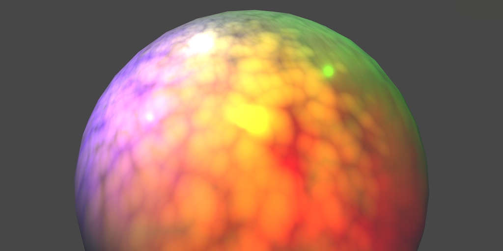
O mighty shader gods, lend me your wisdom! Is it possible to "rasterize" a gradient (in this case - lighting) based on a texel size? I want to try to achieve stylized lighting in my game, I came pretty close by dithering the light info before passing it through the cellshade solution, but either case the resulting edges still look too sharp, and dithering doesn't look good on everything. How can I distort them into more pixely look (faked by a texture on a bottom sphere)?

not related to your question but is your game procedurally generated?
you want to pixelize it?
i think you actually can... with the normal pixelation technique but applied to the uvs instead of a texture sampler
you'll have to try it though
https://forum.unity.com/threads/the-quest-for-efficient-per-texel-lighting.529948/ may be relevant
https://assetstore.unity.com/packages/vfx/shaders/3d-pixel-art-shadows-texel-space-lighting-shader-for-urp-170074 and this if you want a ready-made solution
and this if you want a ready-made solution
God damn and it is exactly what I want. Sadly, out of reach for me since I am unable to buy online T_T
hope your first link will help me, thanks!
I made similar to this, but it requires sampling from a texture, whether it's suitable to your needs or not idk
and this is the texture to sample to

thats just bunch of gradients in single texture, but you can do your own pixelated/blocky like texture so it would follow that sample texture
Hello there! I want to control spacing between glow (white) and background (black). Right now I control with properties Speed of scrolling (sprite is on repeat mode), rotation and texture scale. Problem with texture scale by UV makes spacing smaller or bigger, but also it adds additional tiles. Of course I could make it with photoshop for example, but I would like to control it by properties. I was fighting with it last night, not sure how to take on it, maybe someone has any idea.

Here is top nodes responsible for scaling UV

For me concept of controlling spacing is by decreasing texture width from the center. The problem is that because it is repetitive texture it increases the frequency of columns
Set the texture sampler to clamp
instead of tiling it will just repeat whatever the last pixel at the edge is
But I want to have repetition still, but delayed
If I make texture clamp, then its gonna scroll through it once
are you using time for your scrolling?
Yes
so you can just put a frac node where you are entering the UV's, that will take the fractional component of the output so it will stay at in the 0-1 range
but it still should loop through the whole UV space
And I should set texture sample to clamp, then?
I mean the problem is I'm not sure it is going to solve what you are hoping for in this case the more I think about it
I feel like the path you probably should take is to build the strip procedurally
I'm trying to do it now. Not sure if it's even the good way, how I use it.

That's a good point
I didn't think of that in a first place
YES! That should work!
Thank you!
Yes it's working, thanks again
no problem glad that works
I wonder, can i create a node from a .shader?
Id like to use the output of a shader and extend it in shader graph
Nope
Is there a way to change the emission strenght in Unity Shader graph?
Multiply the emission color by a value.
If you use a color property or node for it, you can set it to HDR mode to expose the intensity control as well
I use a Sample texture 2D node so just a image
That worked! Thanks 🙂
Is there a way to soften/smooth or blurr the edges on my step node? They are really pixelated

Are they pixelated in scene or just in the preview image?
Anyway, you should be using smoothstep instead if you want a smoother step
Also pixelated in the scene. thanks I will take a look at smoothstep
If it's a texture, the pixelation could be caused by texture resolution or filtering
If it's procedural noise it could be floating point inaccuracy caused by extreme tiling or offset values
Best guesses I have
Its a 512x512 noise texture. So when I would have a 2048x2048 texture it wouldnt be so pixelated?
@celest steppe It's normal that the node preview shows pixelation, but texture filtering should smooth it out in scene and game

The filtering seems to fail when the step is extremely close to 0 or 1, since it runs out of information to interpolate
Thanks a lot!
Hi, guys! I'm looking to commission someone (paid, obvs) to convert a vertex/frag/custom geometry Forward-path shader I've written to work in the Deferred pipe /w Lightmaps! It's been ages since I've done this, and I'd rather just...pay to have the problem go away. 😄 Is there anyone out there that might be interested in picking up that work? For further info, it's a custom nostalgia voxel shader that puts a billboard at the location of every vertex of a mesh. Looks like this:

hello! I want to create a shader graph that gets applied to the output of the camera. In the past, I've done this using a 'capture' camera which outputs to a rendertexture, which is passed into maintex of a shader graph, and applied to a plane far above the scene with an orthographic 'output' camera right next to it. Is there a better way to do this?
Trying to accomplish a similar thing : possibly you could use a scaled UI panel that has the render texture as a material? More flexible, wouldn’t require changing the plane size to match different resolutions/ ratios
that's a neat idea i'll give it a try
Would love to hear how it goes
If you're in URP, you can use a Renderer Feature that does a Blit. e.g. https://github.com/Cyanilux/URP_BlitRenderFeature
wow! that looks like just what I need actually. thanks 🙂 and they totally need to add this as an official feature
well it's 2 files if you write it on your own so no need
some screenspace effects you'll want more than _MainTex, with additional textures and passes, so eventually learning about scriptablerendererpass will become useful 😉
the effect I'm making here only really needs the main tex and the depth map, scriptablerendererpass is better I suppose but shader code and blit in particular annoy me.
simple URP Shadergraph outline shader for anyone who searches for it here

not sure where else to ask, but the Gfx.WaitForPresentOnGfxThread is where my shader is taking place right?

hey, I wanna fix the bad shading in #1040095011603222619 - there are screenshots in the thread - I want to change it so the entire triangle will be an average of the vertex colors it's made from, instead of whatever it is now.
Shader "Custom/VertexColors"
{
    Properties
    {
        _Color ("Color", Color) = (1,1,1,1)
        _MainTex ("Albedo (RGB)", 2D) = "white" {}
        _Glossiness ("Smoothness", Range(0,1)) = 0.5
        _Metallic ("Metallic", Range(0,1)) = 0.0
    }
    SubShader
    {
        Tags { "RenderType"="Opaque" }
        LOD 200

        CGPROGRAM
        // Physically based Standard lighting model, and enable shadows on all light types
        #pragma surface surf Standard fullforwardshadows

        // Use shader model 3.0 target, to get nicer looking lighting
        #pragma target 3.0

        sampler2D _MainTex;

        struct Input
        {
            float2 uv_MainTex;
            float4 color : COLOR;
        };

        half _Glossiness;
        half _Metallic;
        fixed4 _Color;

        // Add instancing support for this shader. You need to check 'Enable Instancing' on materials that use the shader.
        // See https://docs.unity3d.com/Manual/GPUInstancing.html for more information about instancing.
        // #pragma instancing_options assumeuniformscaling
        UNITY_INSTANCING_BUFFER_START(Props)
            // put more per-instance properties here
        UNITY_INSTANCING_BUFFER_END(Props)

        void surf (Input IN, inout SurfaceOutputStandard o)
        {
            // Albedo comes from a texture tinted by color
            fixed4 c = tex2D (_MainTex, IN.uv_MainTex) * _Color;
            o.Albedo = c.rgb * IN.color;
            // Metallic and smoothness come from slider variables
            o.Metallic = _Metallic;
            o.Smoothness = _Glossiness;
            o.Alpha = c.a;
        }
        ENDCG
    }
    FallBack "Diffuse"
}
Hello! I have a question that why the "compiling shader varients process" takes too long to build an Android.
My project is 2021.3.5, and I use both HDRP and URP, and I use it while switching desktop and Android platforms. Desktop HDRP projects are based on and build URP Android for connectivity to other devices. I knew that HDRP cannot build apk, so I made an anrdoid build after switching to URP. HDRP material was not used for the scene to be used for android.
But it took 2 hours and 40 minutes to first build. It's a small project that takes 2~3 minutes to build a desktop. Except for the first build, of course, it took about 4 minutes. but even first time, I think it took too long
Is this normal situation? I should continue to do desktop-mobile platform switches often. It would be so hard for me if this happens again every time I add a shader.
The longest part of the build process was where the "Deferred Shader" was compiled. I'm not sure what compiling process is required to build, but do I have to compile a Deferred Shader on my mobile? I don't know if this process is necessary.
I'd appreciate your help

That is likely where all the rendering is taking place, essentially your graphics card is busy at that point, if you want to dive into more explicit information about what your graphics card is doing you can use the Frame Debugger, or a depending on what platform you are targeting there is likely a more powerful render analysis application e.g. renderdoc.
You have a pretty unusual setup there I'm afraid I can't really tell you something specific, but in my general experience the shader compilation pipeline is a beast to deal with and errs on the side of safety rather than efficiency. I'd maybe check out some of the articles around shader stripping.
Oh, thank you!
I'm doing a new test now and maybe it's not an Android problem.
We tested both 2021.3.5 and 2020.3.25 versions in the same environment.
This is the process I tested
- Set the render pipeline to HDRP in Graphics.
- All material changes have been made in the HDRP Wizard.
- I changed the render pipeline to URP.
- Build a simple scene with only camera, directional light, Canvas and TMPro_text.
- Build.
In the 2020.3.25 version, both desktop and Android builds were less than 5 minutes short.
It took 1 hour and 17 minutes to build a desktop in 2021.3.5 version. The Android build also took 2 hours and 40 minutes to test in the previous project (slightly different project scale).
The problem is that I have to use an updated VFX graph. so I can't use it in 2020 version.
I think it's a version problem, but we need to find out more.
Are you using Vulkan or OpenGLES ?
I checked the "Project Settings-Automatic Graphics API"
is Vulkan listed as well as OGLES ?
Turning off the Auto Graphics API and looking at the list, yes.

I'm wondering if 2021 opts for vulkan over OGL due to Unity updates hence the more egregious shader compile times
I'd guess that you already had some build stuff cached from the previous builds on the former version. After switching to a new editor version it had to rebuild from 0 and that's why it took so long.
Try building on 2021 again and see if it's any different?
The first build on the version/platform always takes longer. Medium sized project build from 0 indeed takes around 1-2 hours for me.
Yes, I created a new project in 2021.3.5 version. And I created a scene that was almost empty scenes. After converting the render pipeline from HDRP to URP, I built a Window. It took over an hour
Sound about right. As I said, the first build always takes some time.
However, it took less than 1 minute to perform the same environment in 2020.3.25 version.
I'm a bit suspicious.
Because you've already built on that version in the past..?
So it had some stuff cached and didn't need to build from 0.
I also made a completely new 2020.3.25 version project
I don't know the process of reading Unity Build Cache. Sorry.
Are you mean that 2020.3.25ver project can get the cache built in 2021.3.5
Or is it because I already built another project of 2020.3.25 version before?
If you make a fresh identical(with the same platform/packages and render pipeline) project both in 2020 and 2021 and build the for the first time, they should take around the same time to build.
If there's a considerable difference, it's probably a bug and a bug report should be filled. Furthermore, if any consequent builds of the same project(on the same platform) don't take considerably less time, it's probably a bug as well.
As for cache shared between different projects, I don't think there something like that.🤔
Thank you for your answer! 😃
I will create a new project in a different version and test it further. If it keep having problems, I'll upload the bug report
Btw. All of this is pretty far from being related to shaders. If you want to continue the topic, I suggest moving to #💻┃unity-talk
Oh, yes. I was confused about that too. Thank you! 👍
Do you know if there is any significant performance difference between tex2D and _MainTex.Sample ?
looks like no
Does someone know what are the best shaders for wood eg. on furniture. I use Mobile/ Bumped diffuse but I'm not so happy with the results:

Maybe a bit simple question but I want to save the current pixel color data and re-use it in another pass. Is it cbuffers I'm supposed to look at for this?
or to be more precise
Doesn't look like your normal map works at all. Wait, it looks like it's empty.😅
since i'm working at a lower resolution, every visible pixel is actually 4 pixels in reality so I have 3 redundant shader calls for every pixel, and if possible I would like to be able to discard them, and then in the second pass read off the color of the true pixel and just copy it over
Here's the map of the particular material

It kind works but I'm not satisfied one the overall look of the material on the object.
Ah okay, it's not empty. Is it imported as a normal map?
Yep
Well, if you're looking for realistic look, you should use a pbr shader.🤷♂️
Here are some examples of what I tried. Seems that the second one looks the best 🤔

I can only see difference in tint color.
Same. Overall what would you say which one looks most realistic
I don't think that's possible in a regular shader. At least not in the fragment shader. You can render to a render texture though. Or use a compute shader.
can i "return" the colors to a texture at the end of the first pass, or at least write to a texture in addition at the end that i can read from in the next pass? i have never done any texture writing in a frag shader so idk if or how it works.
maybe that's where the render texture comes in
maybe the same way you do antialiasing ??
i'm doing 4x as much raymarching as i need to so i'm pretty desperate to get rid of these pixels, even if it's a heavy solution
You can return a color, yes. That's what fragment shaders do usually. The GPU then writes that color to the render target.
I'm not sure if it's possible to render to several render targets. Might want to research that.
I'm also not sure if the results of the first pass are available in the second pass(it would make sense if they are, but it might just be the render target color buffer), so might want to research that as well.
Also this post suggests, that it's possible to write to structured buffers in fragment shaders. Might want to test it.
https://forum.unity.com/threads/setting-buffer-data-from-inside-fragment-shader-to-be-read-from-c-script-urp.1229175/
Thanks I'll take a look.
Would be interesting to know how you solved when you do, if you don't mind.
sure no problem i just need to figure out how to set render targets
Heya, just a quick question, does anyone know why the light node isn't working?
I am using 2d renderer, mostly default options

Is it actually "2d light" texture or light "texture2d"?
are threadgroups in a compute shader kind of the same as screen pixels? like if you're trying to work the screen with a compute shader do you dispatch it with threadGroupsX andY set to 1920, 1080 and use the uint3 id in CSMain like a for loop kinda??
gpus execute work on threads in fixed size groups called wavefronts
they are usually around 32 or 64 threads per wavefront
when you use numthreads, you tell the shader compiler how much threads to have per one of your group
if the number of threads in your group is less than the wavefront thread count, some threads will idle
but if you have more than needed your gpu only has a limited amount of registers to keep track of the wavefronts, and it may not work or you may get reduced performances
the case is usually to just play around with numthreads to see which config works best
but one case where you benefit massively from thread groups is when you use groupshared memory
but even if you don't use it, it's still important
yea i saw something in a thread just now https://i.stack.imgur.com/NPvbf.gif

idk if this is an example of wavefronts
the id from SV_DispatchThreadId is the same concept as vertex ids or particle ids
but i'm currently trying to move a shader over from my fragment shader and attempting to work it in a compute shader, and i'm trying to figure out how to translate i.screenPosition for example (ComputeScreenPos(o.pos);) and i was wondering if the id was similar to that, in the sense that it represents an index in the block of data sent for computing
so i can just use id.x as the position in the data
you should be using a 16x16x1 compute shader for postprocessing effects
but yes
id.xy is your screenspace texel position
alright thanks
ideally you should not be using compute shaders for postprocessing effects unless you have to
i'm rendering tiles on a quad and i'm trying to figure out faster ways to do it than my 1700 line frag shader
you won't see speed improvements unless, you use the aforementioned groupshared variables
your usecase of rendering tiles may be able to benefit from it so i suggest you do look in to it
a lot of it went over my head but i'll try to keep it in mind.
the groups and thread counts is kind of hard to really understand without knowing more. i'm not sure if it means I should just send a large amount of data into the compute shader and have it handle it, or if I should split it manually and just send smaller batches of data into the shader. but i'm not asking you to explain compute shaders from the ground up, i literally just started trying to figure it out an hour ago.
for example right now my frag shader is repeating my raymarching on 3/4 pixels that don't need it, because i'm actually rendering a 960x540 resolution in a 1920x1080 window
so this relates back to my previous question
and my current idea was to use a compute shader and write it to a texture that i can then send to the frag shader and it just copies the pixels
take it slow, keep in mind though, if you do a 1:1 port from your fragment shader to compute shader you're likely to see slowdowns than improvements due to vendor-specific pixel ordering methods for fragment shader that dont exist in compute shaders
it's the gif you posted earlier
right
and yes you can have the same setup as with your fragment shader on your compute shader
Texture2D<float4> _MainTex;
Hello, how can i create a shader with parallax mapping using this node ? I dont understand how it works

then you'd cmd.SetComputeTexture() if you're using command buffers or just computeShader.SetTexture
and for output you'll just have to write to a non-const Texture at the end of your compute kernel
parallax mapping is faking vertex displacement, if you're using a proper heightmap you're probably doing it right, you just have to replace all the uv0 nodes in your graph with the parallax uv
alright thanks
Well i tried this
But the result is quite weird


ofcourse it looks weird
Without parallax :

it's an illusion
that doesn't really work
which is why tesselation shaders exist
for real vertex displacement
I know, but i've seen results using the same node way more convincing, i feel like the creases here are not where they are supposed to be following the heightmap
Let me show you with a gif
It look like i have the correct shape but the texture is not projected correctly

I am having an issue. I fill all my buffers with relevant information. Call Graphics.DrawProceduralIndirectNow(MeshTopology.Triangles, bufferWithArgs); And it works the first time but when I do it again the buffers were not cleared. I release the buffers in the OnDestroy method.
Is it possible for a buffer to keep its value in the GPU even after I call the .Release()?
i found something https://stackoverflow.com/questions/63062441/global-tiling-in-hdrp-combined-with-parallax-occlusion-makes-messed-up-uvs
Stack Overflow
I'm trying to make a custom shader with Shader Graph on HDRP. The intention is to automatically tile textures based on global position so I don't have to worry about remaking materials when I resize
Thx I'm checking that !
after you call release the values in the buffer is unknown
if you want to reuse the buffer dont release it, just call whatever you want with the buffer and only release when you no longer need the data in the buffer
This worked ! Thanks a lot
Yes !
yeah, there's confusion for the 2 nodes
Yes x)
Thank you again
Do you know if this is heavy to use ? Or it is ok to have it on a lot of surfaces
a workflow using proper tesselation will probably be better in the long run, but if it works for now you shouldn't worry about it
Ok ok I see ! Thanks !
is there a way to get a shader to writ to a custom render texture in urp? Sorta like unitys depths texture
Hi, I am using URP 12 and Unity 2021.3.4. I have some custom shaders from an asset and I'd like to use a cookie on a spotlight, when shining on this shader, my cookie doesn't show. When shining on the standard lit it works fine. Any clue on how to fix this?

I think this is possible with a custom define.
Not sure what it was exactly but it might get you going
it should be URPs 2D Light Texture Node
https://docs.unity3d.com/Packages/com.unity.render-pipelines.universal@12.0/manual/2d-customlit.html?q=2D Light Texture Node
figured it out, i have to select custom sprite lit shader graph, throws an error in sub-graph 🤷♂️
hi, i switched to urp, and at the moment your shader doesn't work anymore because of that
oh im stupid sorry for the ping :/

Has anyone figured out how to access all of the terrain splatmaps in a Shader Graph?
Or at least more than the first 4
you can export them, no?
Thanks for the tip, though I would need this all to happen at runtime, since the terrain is procedural. But I'll look into it, maybe it reveals some info on how they are stored internally.
Currently I am accessing the first four layers from shader with _Splat0, _Splat1, _Splat2, _Splat3, but that's it 😔
i feel like you'll have to use more than 1 material
The problem isn't texture sampler limitation or whatever, because I am in HDRP/Shader Graph
it's that _Splat4 etc don't exist 😄
Even though I have 8 TerrainLayers on my terrain
My custom terrain shader works perfectly but just limited to these 4 layers.
And the splatmap control which is _Control only has 4 channels.
Tried to look for _Control1 and similiar but they don't exist
are the _Splat layers alpha/red only?
Those are actually the Albedo textures of each TerrainLayer
They get fed into the shader as properties automatically, apparently
Then _Control texture stores the blend for layers 1-4 in the RGBA channels
i think this is just a limitation of how the unity terrain systems deals with terrain shading internally
though im unsure, you might need to roll your own solution with Texture2DArray
Thanks, ill look into Texture arrays. This is my 4th time asking this and youre the first to respond 😅
In shadergraph, u can change the preview to a 'custom mesh'. I exported one from blender and imported it into unity, but for some reason it's not appearing in the selection box for custom mesh. Any ideas?