#archived-shaders
1 messages · Page 17 of 1
I see, so mesh makes duplicates but sharedMesh doesn't
Even if it was making duplicates I'm not sure how that duplicate could be referenced but I changed it to shared mesh already
Yes. Generally you should always avoid using mesh/material and similar properties that have the Shared version. Especially if you're assigning via the property.
I feel like I'm doing that for something else that isn't a mesh aswell though
I'm looking for it now
I'm setting textures using material instead of sharedMaterial
but it only does that once
It doesn't matter in this case. GC doesn't always clean objects that are not references. Some objects can exist in the memory without being referenced.
interesting
That should be fine. It should create a new material for the renderer, but that's fine as long as that's what you expect to be doing. The issue with you using mesh property is that you assign to it. Basically, unity duplicates the previous mesh, then you ignore it and assign a new mesh to it.
Then use the memory profiler as I suggested.
The addon one?
The package manager one.
Ok, one sec
Ah, I think I remember how to do it in the regular profiler. There should be a button to sample the current state of the editor.
Can you take a screenshot of the whole profiler?
Here's the bulk of the memory, apparently most of it is for profiling and System.ExecutableAndDlls (whatever that is)

Ok
Ah, that's what I was talking about

Any idea what it is?
Did you restart the editor?
No
Lol. Why not?
I told you that the meshes from before the changes are still there.
I'll do it again
With shared material for bonus
Ok, baseline memory usage without unity is 51%, thanks computer
Gosh, unity does this thing where like half the time the editor takes like 10 minutes to open and like 15 seconds the other half
I'll even do obs recording with profiler
One sec
Managed to get it to 91% memory
And here's the profiler

Might want to switch the profiler to "player" mode and try again. You're editing the mesh in play mode, don't you?
No, this is in edit mode


Could it be the mesh collider? Try commenting it out and see if that changes anything.
ok
Also try using the package manager memory profiler. It should show more info.
Finally, are you sure that the unity memory consumption keeps on increasing? You said that your PC already consumes 51%. So 40% for unity is not that much.
If I didn't stop my computer would crash
Would it really?😅
Yes, but that's happened before with the compute shaders so it's only ever frozen my computer with this instance
I could sacrifice my computer if you want but I don't think the memory buildup is sustainable
It could happen with VRAM being overfilled, but it should be fine with RAM. Your PC would just start caching to the hard disk.
Anyways, use the memory profiler.
I think that happened once and I had VERY low memory (e: disk space) on my pc, it was not a fun time
I'm going to test again now
It still happens without the collider
currently downloading memory profiler
the fear of all compute shaders
It's not compute shader fault though.
You'd get VRAM leak if it was due to a compute shader.
What's the difference between VRAM and RAM?
It's something you're doing on the CPU side.
VRAM is video memory. The memory on your GPU.
RAM is what your CPU uses.
Ah, so it doesn't stand for Virtual RAM?
Nope
Wow, those freeram.com sites need to give me some answers then
Ok I am trying the memory profiler now
Let me guess, I capture a screenshot?
If you want me to have a look, yeah.
It says it will share a bunch of personal sensitive info, is it ok to just send the summary?
Lol

And they all have 0 references
How could it be creating all of those if I'm using shared mesh, could it be because i use new Mesh()?
Maybe there's another place in your code you're doing it?
Also, share the updated code with sharedMesh
Do they have names or anything that might point to their origin?

Maybe try destroying the previous mesh before assigning a new one🤔
Ok, one sec
I guess it's not collected by the GC since it's considered an asset.
It's still going up
        Destroy(filter.sharedMesh);

        Mesh mesh = new Mesh();
        mesh.vertices = meshVertices;
        mesh.normals = meshNormals;
        mesh.triangles = meshTriangles;

        filter.sharedMesh = mesh;

        collider.sharedMesh = mesh;
I think you should call DestroyImmediate in the editor.
ok
You're a legend my guy
Did it do the trick?
My memory usage is as mediocre as it should be
yes
In playmode should I use destroy instead?
Yes
Ok, perfect, thanks so much for the help.
Make a check to see if the app is in edit or play mode.
Ok, the profiler should be really useful from here on out aswell
How to correctly strip Shaders for terrain. As my build have quite crazy amount of shaders included for terrain (hidden ones). I am using addressables and webgl Build.

Got a problem. The material made from a shader graph has exposed texture slots. When I put in a texture into the slot the material preview shows the correct texture but the actual texture slots is showing the wrong image.
Not a big problem, only an editor problem
NVM I restarted unity and now it's working...
am i doing something wrong here?
this is code for URP
float calculateFresnel(Light lightSource, float3 wNormal, float wView, float Intensity)
{
    float fresnel = 1-dot(wView, wNormal) * Intensity;

    float3 H = normalize(lightSource.direction + wView);
    float3 NdotH = saturate(dot(wNormal, H));
    float3 output = fresnel * NdotH;

   return output;
}
it ends up looking like this and im not too sure why. it worked fine in built in

@karmic hatch something weird started happening on the water shader (when testing in Unity 2022.2.0b9 which doesnt happen in 2021.3.10f1)
for some reason as soon as i set the 2nd normal map a huge part of the water light reflection is mostly white / too bright 🤔
why is this happening
how to solve?
problem happening in unity 2022.x

problem not happening in 2021.x

i tried going through & comparing various light-related settings and match them up as close as possible
problem not happening if i only use 1 normal map instead of 2

this is the shader pretty much

Is your nroaml map set as a normal map?
Where?
in the project image inspector settings dunno what it's called
image properties
jsut click the image and then the inspector
The texture import inspector? Pretty sure yes... Lemme double check...
🙌 you win
i surrender
weird thing - in 2021.x it was also NOT imported as normal map, but still worked... 🤷♂️
thanks @round patrol
That was easier than I was expecting. Glad to help
does anyone know how can i write to zbuffer using custom code, for every vertex i want to set custom distance from camera and not it being calculated automatically?
eg. I calculate my special distance in vertex shader and want the zbuffer (depth buffer) to use that distance

I think that's done in the vertex shader when the vertex position is multiplied with the MVP matrix. So you'll need to adjust it during or after that calculation.
so its in the clip pos?
Yeah, I think so. Try modifying the clip post and see if it has any effect.
thanks its in the clip pos
Needs reflections 😉
After doing the dynamic real time reflection probe, I made a grid of baked reflection probes to test with. Ran into the single-probe-per-object issue when using one large plane for water.
Worked great with a small dynamic object (reflective sphere)...it switched between probes and faded between them just fine. But one large plane....oy.
It kept using the default reflection probe (auto generated by sky manager). It's object relative, not camera-location relative. IDK how/if it can be hooked up. Need to research.
You can test if you're using the default probe or not by changing the settings in lighting, setting the intensity to 0.
how do i make a toggle in the material inspector for toggling multi_compile's?
nvm, i figured it out
but then i have another question, is it possible to hide certain material properties if certain keywords are on/off?
I am using URP 3d and with a freshly created shader which looks fine in unity I get this when I look at it on my Quest. Now it is a bonelab level so it could have many reasons its just that I don't really know where to start. I am using the correct rendering pipeline and the material is as basic as it can get. Does anyone have an idea what could cause this?

Unity on the left, bonelabs on Q2 on the right
do you mean it might work better if i chop up the water plane into a grid of subdivisions? maybe 1 per probe or something? or that's not gonna blend well either.. like it might look wrong on the border between 1 section and the next section..
maybe it's a Unity shader which can be modified/adjusted or something?..
sorry having a hard time parsing; do you mean default probes that are placed around in a grid? or some default probe used for the skybox or other? and not by changing what about the lighting settings - so then what should i set (if anything)..
hi. I have been trying to learn hlsl for writing shader code for a while but implemeting lighting is really really hard. In adition to this there does not seem to be a library with a few of the comon shader graph functions. I am concidering going back to shader graph but I am not sure if I should continue to try or return to the graph. Does one have other advanatges over the other (apart from ease of use)?
You can do more with hand-written shaders than with shader graph (e.g. loops, shader graph also doesn't have a built-in 'get main light direction' node). But usually you can get by with just shader graph since it can do most things, you don't have to worry about syntax, and it's arguably easier to debug.
Alright. How does lighting for shader graph work? Does it just work straight out of the box or do you need to setup to get all light sources to work with it.
There are Lit graphs which handle lighting for you.
But if you want custom lighting models (e.g. toon/cel shaded) you would need to use HLSL code in Custom Function nodes. (For URP at least, unsure if it's possible in other pipelines)
e.g. https://github.com/Cyanilux/URP_ShaderGraphCustomLighting
That is usually still easier than writing the whole shader from scratch.
The main places where you probably would avoid graphs is for UI, or requiring ColorMask & Stencil operations, as it doesn't have good support for those.
Does anyone know which UV map slots are free to be used? I know Unity uses some for lightmaps and such
obviously UV0 is fine to use, but UV1 is used for lightmaps... is it okay to use UV2 and UV3?
I think Unity can also use UV2 (well, Mesh.uv3 in C# but UV2 / TEXCOORD2 in shader) for realtime lightmap UVs. I guess for Enlighten Realtime GI?
Mentions it here : https://docs.unity3d.com/Manual/LightingGiUvs.html
Right thanks, basically making a list of what each is used for
With lightmaps I assume if I turn off the generate lightmap UVs option I'm good to use it
Maybe similar with UV3 if I'm not using realtime GI (which I'm certainly not going to use in VR)
How would I add a simple falloff like The Inverse square law To this Shader.
here's what I'm using it for like a cone of vision thing for a guard


1/dot(corner of triangle - fragment position, itself)
It might/will, but that doesn't mean everything will align well. It just means it will work somewhat compared to not at all? I haven't tried it yet. The border overlap areas are where the blending happens...one view is faded out and another is replacing it (that's for a small object though, it's not per-pixel).
Nope, I'm saying that my grid didn't "get selected" by the logic that assigns the closest probe. So somehow the "closest probe" to the water object was the default one. I'll have to check the origin, but no matter really, since unless I break it up it's not a good solution to have one big plane and try to use reflection probes.
wdym by corner of triangle
wait do you want it to fade with distance from the camera or distance from the guard
distance from guard
ok so if you have the coordinates at the guard's head then that's the corner i mean
I can Input specific coordinates?
if you don't already know it in object space, you can have it be set on the c# side (create a Vector3 property for it in the shader, then set that property with the script)
wdym by itself?
if you want the opacity to fade off like that, yes
calculate (corner of triangle - fragment position) and then put it into both slots of the dot product
like this

yes
also instead of divide, you can use a reciprocal node
and then just as a general rule, saturate it before putting into alpha
So Like This?

yes
how can i convert a color into a white/black mask?
Anyone have any idea why this specific material is tinted entirely blue when viewed through a transparent material, but not any others? You can see the blue disappear when I move the camera inside the hologram wall, and at the end I go fly close to a different wall material that isn't doing the same thing.
https://streamable.com/jqg03o

It's a shader graph shader so I can't just post the code for it. If anyone needs to see a specific part of it I can try to screenshot that group of nodes so I don't need to post a screenshot for ants of the entire thing at once
actually, i would need it to be greyscale. i tried using step() to make it a pure white/black but that didnt turn out as i wanted
Actually, I think I found it, it's the intersection highlighting, it's just too close to the mesh. The others have more of a gap between them. Thanks for the 🦆 though
basically you just want the V from HSV or B from HCB
Does anyone know why I'd be seeing this error with a shader I wrote?
ArgumentException: ComputeBuffer.SetData() : One of C# data stride (28 bytes) and Compute Buffer stride (16 bytes) should be multiple of other.
UnityEngine.ComputeBuffer.SetData (System.Array data) (at <edb09cd490414b2684a18fe60d255a59>:0)
seems pretty straightforward, no?
I honestly don't understand lol Really new to shaders @shadow locust 😦

Anyone?
Figured it out nm. Thanks
@stark dune I am super new to shaders. However, if you are looking to change your shader surface values, maybe try this:

I'm using graphs
I know how to change values, I just can't get it to give me both sliders/colors AND a map option
That's a special material property drawer on the C# side.
https://docs.unity3d.com/ScriptReference/MaterialPropertyDrawer.html

Oh so it's not possible with graphs?
The shaders/graphs set WHAT is input.
The Unity editor property panel shows the settings, so that's on the engine side. You'll see a default, but can override that with material property drawers.
IDK if you can duplicate the exact style or not, I never bothered to try. But I'd guess you can.
float3 bwColor = luma.xxx;```
(I haven't checked it in the compiler, but that's the idea)
you might even be able to combine that into one statement for brevity:
```float3 bwColor = dot(sourceColor.rgb, float3(0.2126729, 0.7151522, 0.0721750)).xxx;```
Of course you can convert all that to "nodes" if you like pretty pics (using dot product and swizzle).Do you guys have any resources for scaling the UV of a material based on distance via code? Without writing a new shader
How do you access the item at index 0 in a StructuredBuffer? My shader is currently doing:
positionBuffer[unity_InstanceID]
but I'd like to instead get the value at index 0 doing
positionBuffer[0]
Did you try it?
I'm writing it out right now. Need to make a few adjustments. But thought I'd post here to save me the time if someone knows
There's no reason it shouldn't work. Unless you write to it.
I was originally passing an array of structs where each struct instance just has float x,y,z. But each struct instance also has their parent transform x,y,z (it's the same for all array elements). So to be more efficinet, I'm just going to pass the parent transform in at index 0. If possible
If it's a hierarchy kind of thing maybe use 2 buffers: one for positions and the other for indices of the parents.
Can you pass two buffers to a shader?
This is how I set the buffer currently:
material.SetBuffer("positionBuffer", positionBuffer);
You can pass as many as you want. There might be a hardware limitation, but it's probably quite a lot anyway.
What about it?
Could I use that to set the parent x,y,z and have it accessible in the shader?
So calling SetBuffer won't override the buffer as long as I supply a different name correct?
Is there a way I can make exposed vectors less than 4 show less boxes? Its only a Vec2 but there's four boxes


I'm not sure if global properties alike that are accessible in a compute shader. And if it's a regular shader, I'm not sure what are the implications of using it.🤔
I'm using a surface shader. It's for GPU instancing
Correct. You'll have to define it in your shader too of course.
As I said, I'm not sure about it. Although I think it has a size limit of 1024 or something.
if my water shader simply does not do any vertex manipulation, so the water plane is always flat, only illusion of movement is from normal maps
is there a super easy way to make an underwater fog then? it could even be "hardcoded" as: "anything below world Y position of 100 should render this fog effect" ?
basically - how can i achieve this underwater distance fog effect, only when camera is positioned underwater

so i created a new Universal render pipeline project
and i created a cube game object
but it wont let me change the shader or the material

Make a new material and drag it onto the mesh renderer
No clue why the default lit shader is erroring though
could be the Stress Level Zero Custom URP
I think there are many ways to achieve that. One would be to apply a post processing effect only when the player is submerged.
ok
since i'm aiming for mobile - any chance there's a shader effect that might do it for "cheaper" ?
You will need a shader regardless.
Postprocessing is just rendering a full screen quad with a shader after all.
writing to the depth buffer with the water's bottom side will help aswell
perferably for free
do you guys have any idea where i can learn how to make a shader that auto textures terrain from height and slope perferably for free
On the internet of course. Sounds like you're looking for triplanar mapping + some logic to get a texture from the height of the vertex/pixel.
@kind juniper well ive been looking and havent found much am i possibly searching with the wrong question
Perhaps. You wouldn't find exact solution, but you can find pieces of knowledge that you can combine to get what you want.
I imagine you're doing some sort of custom terrain solution?
In this case maybe check the Sebastian Lague channel on YouTube. He has a series or two that could be relevant.
Then there's the "catlike coding" website that also covers many relevant topics.
i forgot about him duhhhh idk why i havent checked his channel
Thank you @kind juniper
Brackeys is also good @halcyon plank
nope i cant do it sabastian basically requires to be using his terrain setup and for brackeys i cant find anything
i tried to do what subastian did in shader graph but i could only reproduce the grey scale effect
i have a thought; you could give each texture a weight that's a function of slope (dot(normal, up)) and height (position.y) and then do a weighted average
(if you want it to fade)
@karmic hatch that is true let me try that rq
https://i.imgur.com/GT81KJU.png
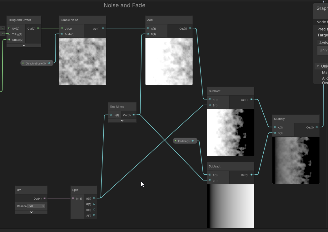
So I've been playing with the graphs more, following some tutorials, and now I'm experimenting with them. However, I'm having a hard time trying to understand how to merge some of these nodes, such that I get the desired transparency on my shader. It seems that multiplying those two subtraction operations will always result in my alpha channel inputting 0, even though the node display right afterwards is not completely black. If anyone could help me understand how to merge this stuff together correctly I'd appreciate it.
Is there a way to make a shader to display through it only specific objects? like some selective window that has lots of junk behind the window but it will display only specific stuff though it
Assuming your uvs are mapped in a way similar to the preview window(0 to 1), it should look the same way.
I fixed the problem by inverting after multiplying those two subtraction methods, but the node display is incorrect
really wish you could see values in this thing
I think that'd require more than just a shader. In urp you'll probably need to use the render features. And/or maybe several cameras. I suggest looking at how see-through effects are done for characters to be visible behind walls. You'll have to use a similar technique.
The problem is that when I multiply those two nodes which I previously subtracted, the alpha is now (or less than 0). I would like both, the noise and the fade, to be applied to my shader, but it seems trying to combine them how I am creates problems.
im using built in render pipeline, is there a cheaper way to do this? without additional cameras
I can use one of those nodes fine and it will work, but trying to combine them does not.
Inverting does fix some issues surprisingly, but the noise becomes reduced by a lot. Pretty complicated some of this stuff and the tutorials kinda spread thin on the actual logic of it all.
Saturate it at the end (saturate === clamp(0, 1))
Ah, yeah I remember watching something about that. But, it still seems to be clamping at 0.
You seem to be using an opaque material with alpha clip, is that what you want or do you want a transparent material?
I'm using transparent
I think you need to turn off alpha clip if you want it to fade smoothly
If I'm blitting a shader into a Render Texture but I only want change a region of it, how can I avoid needless processing of the areas I don't want to affect?
I've been just messing around with that, but even then the preview is completely transparent.
I'm obviously doing something I shouldnt be doing with the operations, just the nodes are lying to me lol
What settings are you using

You might not have set the properties in the material in your scene
It kinda is showing up after resetting, but color isnt being applied now
The saturate may have helped
Ill eventually figure it out, just gotta fool around with it more
ty tho
I'm sure there are at least a few ways to achieve that in birp, but you'll have to research that. I don't have any experience with that effect.
Maybe "abs" the value/s before/after multiplying?
If the issue that the values are negative
wdym not being applied
Yeah they are negative I think
So clamping them results them in 0. Inverting them or abs does do something, but kinda reduces the noise to nothing
What noise?
I've got some noise and a fade effect which work fine independently, but trying to multiply them together gives me a node with the preview I want, but negative alpha
turning alpha clipping off with the saturate does give me the exact shader effect I want, but it removes the colors.
Is it just grey?
Yeah
The colors are set properly in the material?
They are, but I also have the preview on the graph with a default material
Is the graph preview also grey?
Yeppp
Can you show me the fragment node and preview?
Are all the other nodes working fine?

I think the background is grey, so you're seeing the transparency. Try just putting the color from the lerp into base color directly
Or switching the blending mode to additive (and then removing either the alpha or multiplying the base color)
Since the alpha is usually low, when you multiply by the gradient it just makes it very dark compared to everything else
(or so I theorise)
Oh also make ambient occlusion >0
And smoothness, you probably want <1
I'd check if the noise is returning -1 to 1 values?
It's simple noise so iirc it's 0-1
Yeah, doing the lerp directly does apply the color now.
How do I even check for values on this thing besides just eyeing it
Eying it is usually the way, you could put a step at some value you're interested in or multiply/divide some quantity with a small/large range so that it's more manageable to look at
I've got to head out, but I think you've got me on the right track.
good luck :)
Appreciate it yo
So you're right about the gradient becoming way too dark. Seems like the more operations I applied to the noise, the darker it got mixed with the alpha levels getting way too low itself and getting clipped.
Overall, it works now ty again ;)
ok. I guess when you mentioned "there are many ways to do it" made me wonder which one might be the least intensive / most performant way to go for mobile... i dont know much about rendering & shaders but i thought i remembered that shaders on the scene object (fragment shaders specifically it's called?) is more performant than post processing effects, or something like that... 🤷♂️ could be i'm totally off about that
ok, may I ask - how do I do that?
if there's some tutorial or step-by-step guide i could follow to achieve this, would be very helpful... unfortunately still quite noob to shaders 😬
thanks 👍
I was using ShaderGraph in this case (from another step by step tutorial i was following) does this setting exist somewhere that i can enable it in shadergraph?
maybe depth write in this pic
(sry for ping Mao lol)

ok cool so once i have that enabled (assuming that does the same as ZWrite on) now how do i put it to use when swimming underwater
wish there was a guide i could follow for this effect (postprocessing or however it's done)
or if someone could point out an Asset in the store which does this effect ready-made i'd prolly buy it. The only thing is I was hoping to get the plain raw effect as-is without too much other complicated fancy effects, only what i need, since i'm trying to cut down on intensive computation for mobile
i'm guessing i need to use this position input with World space selected? also leaving "Depth Write" as Auto should be OK because it will be automatically enabled when needed/used?

Hey, I'm trying to create a water shader which changes the water colour based on its distance from underlying geometry.
I'm following the Unity tutorial linked below which does this but it does not quite fit what I need.
https://www.youtube.com/watch?v=gRq-IdShxpU&t=148s
As for what I need help with, it appears the camera's position also bares a factor in how the colour changes in addition to the geometry below the water.
This is how it looks when the camera is completely overhead
https://i.imgur.com/PyTPMH8.png
This is how it looks at another angle
https://i.imgur.com/nGkKNZv.png
And lastly
https://i.imgur.com/krFoc2B.png
If there are any suggestions on how to remove the camera's influence, it'd be much appreciated
This is the current graph
https://i.imgur.com/rEjbYa2.png
Please ping if you respond
hey I'm working on a sprite shader and I'm getting these weird patterns around the sprite. it probably has something to do with alpha, but not sure what's going on. anyone know what this is?

oh I just had to connect the alpha channel lol
a classic :)
I think part of the camera's influence is a bias towards the center/edges, which you can remove by dividing by the b component of normalized view space view direction (might need to negate). The other part is just that the distance along the line of sight between two planes is much larger if those planes are at a steep angle to the ray, vs if they're at a shallow angle. That is expected from the geometry of the system (though you can get rid of it by dividing by the g component of normalized world space view direction (again might need to negate)
any idea why the URP/Lit (PBR Workflow) shader causes materials to be invisible?

https://docs.unity3d.com/Packages/com.unity.shadergraph@12.1/manual/Normal-From-Height-Node.html
I am not working in the latest version of shadergraph/unity, so I copied the code from Normal From Height's latest into a custom node.
It looks MUCH better than the version's normal from height I currently had, but for some reason it creates this very minor discontinuity at the corners of my mesh, which the old NfH doesnt do

the older one that looks less good but doesnt have the discontinuity

I did notice there is a weird circular band of weirdness in the preview

oh here we go, it looks awful on a capsule

void NormalFromHeightTangent_float(float In, float Strength, float3 Position, float3x3 TangentMatrix, out float3 Out)
{
    float3 worldDerivativeX = ddx(Position);
    float3 worldDerivativeY = ddy(Position);

    float3 crossX = cross(TangentMatrix[2].xyz, worldDerivativeX);
    float3 crossY = cross(worldDerivativeY, TangentMatrix[2].xyz);
    float d = dot(worldDerivativeX, crossY);
    float sgn = d < 0.0 ? (-1.f) : 1.f;
    float surface = sgn / max(0.00000000000001192093f, abs(d));

    float dHdx = ddx(In);
    float dHdy = ddy(In);
    float3 surfGrad = surface * (dHdx*crossY + dHdy*crossX);
    Out = normalize(TangentMatrix[2].xyz - (Strength * surfGrad));
    Out = TransformWorldToTangent(Out, TangentMatrix);
}```
What in unity's code could be causing this?
my only guess is the tangent matrix
because I didnt know what to sub into that
hey, thanks for the input.
Your assessment makes sense to me so thanks for pointing me in the right direction.
As for the execution, It'll prob take me a bit but I'm sure I'll get it sooner rather than later
float3x3 TangentMatrix
How do I substitute this? What is it? Its the only thing I can concieve is wrong because I dont know what it is
I need to know what this 'is' in the original node so I can replace it in my custom one

google doesnt have the answer

a random post on the net said its this, but that doesnt work

hm it looks like it WAS that, except in object space instead of world space
discontinuity is gone

hrmgh that didnt actually fix it
the end result looks totally janked up from certain faces

how can this happen?

okay this fixed it, after setting the right transform matrix, I had to pass in the object position instead of the UV position
peeps
can we use PBR on built in pipeline ?
Sure! The Standard Shader is PBR.
So are the Surface shaders if they use the "Standard" lighting model.
@karmic hatch In your SSS shader, do you recall what controls this range here? I've tried adjusting every value but nothing I change affects that depth in any way
I am trying to make the cutoff less stark and discontinuous

I'm trying to create a water level mask from a height map. I'm getting close just not quite there.
Here is a better visualization but imagine it had a little blur.
plugged away at this but despite my best efforts, I manually tried changing every single mathematical value at every step of the way, I can't find the source of that discontinuity, nothing removes it, nothing moves it, I cant find it's source
Hey does anyone know how I can access the world position within a compute shader
I can get the camera UV for my scene, and it works fine, but I want to use the world position


Pass it in as a property
since I cant fix its source problem, how can I hack a fix, how can I force this specific range of values to not be all the same value? I want a smooth gradient down that side instead of the discontinuous one I have now

Thats the thing... Im not really sure how
like... do I use the camera to world matrix thing? I attempted using that before and it just does some weird stuff
Check the compute shader API. There are multiple methods to set properties like vector.
Thats... not what I mean
I need to get the position in the first place
where do I get that
Transform.position.
Yes. That's why you set it from C# script. Via the ComputeShader api
So you need a position of a pixel?
Its a global UV... not transforms..

I cant just create this transform in the C# script,
Currently its using the position of every pixel on the camera
which works, but it follows the camera, when I need it to follow the world position
Well, you can't get a world position from that. You need some reference point.
I know theres a way to get the world position... I just dont remember how honestly
Not in the compute shader.
In a fragment shader unity does all the job for you, so you can just access it.
Do you have an example?
In compute shader you'll need to make the calculations manually. I don't understand why you'd need to do it though?
Because Id rather not have the world following my camera.
For example like they do here:
https://answers.unity.com/questions/1272511/getting-the-world-position-of-the-pixel-in-the-fra.html
Why are you using a compute shader there in the first place??
Because Im making a custom renderer..
This is a raymarcher
(its in 2D)
Just have a plane/quad in the world with a material.
lol
no..
that would ruin the whole point of having the raymarcher in the first place
Im making the raymarcher because I have a project that requires a raymarcher
theres certain things that geometry and meshes just cant do
Okay. Then you'll need to include your camera's position in your calculations.
So we're back to setting a shader property from C#.
I told you. SetVector or something
._.
Check the Compute shader api

Random you are wasting your time
If I wanted someone to tell me I needed to change something in the script, I wouldnt have asked for help
apparently so
I'm not skilled enough to help you but I can at least recognize that
That's gonna depend on your raymarching logic. You should know where to add it if you understand what you're doing. Regardless if it's unity or not.
no... it doesnt depend on the raymarcher lol
its literally a UV..
a fkin UV
I just need to access the UV centered and scaled on world origin
I dont get whats so complicated about that
The uvs is relative to your camera, correct?
yes.
So without the camera position and orientation you won't be able to transform them to their world position.
look here at the green outline, thats the real position and size of the object
It uses the global position of objects in the scene
but its rendering the world origin as the center of the camera screen
so its like the world is following the camera
even though its really not
You probably need to transform the uv positions using the view matrix of the camera. But you'll have to research that on your own.
thats the whole reason I came here
and the reason Im quite irritated with you.. Im well aware of what I need, Im asking how exactly to do it
if you arent sure, just dont reply and wait for someone else to help me
it was the low value on the remap, the one I set to -0.2
Is there a way to create a decal shader without using urp or hdrp?
Well im sure that the build in pipelie has tons of examples. This blog post has a pretty decent example of a deffered decal system

Thanks! Are there any tutorials? Im pretty new into Unity and shaders and every Youtube tutorial I found was not working for me because they used Urp or Hdrp
I suppose that the new render pipelines are overtaking the BiRP in search results, but there are 100% tutorials for the old shaders
But if yoy are new
Why are you using the build in render pipeline. urp and hdrp are the future and I would suggest for you to learn urp and stick with that
Okay thanks I will take a look if I find any older tutorials. Unfortunately my project is using the build in render pipeline and I cant switch that easily
Well, with respect, you could have laid it out better from the start....like the fact that you're in 2D (you want a ray marcher in 2D?) and that you're ray marching effects/worlds.
Maybe use your google fu and see what you get when you research "reconstruct world position from depth buffer". 😉
in 2D, you'd have a relatively fixed z value, but otherwise I suspect you can get the necessary transformations.
BTW, generally in ray marching you're going to end up having to ship the geometry/SDF/whatever data up in compute buffers anyway...so when you do a "ray hit" you'll end up knowing what polygon you hit and more importantly you'll know the vert world-positions. You could use barycentrics to interpolate across the polygon if you get clever.
How would I go about making a shader graph, that takes in a 2d texture, and applies it to all sides of a cube while staying tiled nicely, regardless of size?
If you want the texture to stay the same size (is that what you mean by "tiled nicely"?)...check out triplanar mapping. There's a node for it.
You could possibly work out a system to use object space but adjusted by scale. Or if you don't mind that it is axis aligned, you could use world space and that would take care of the scaling regardless of object size, but it won't rotate with the object...try it and play with it and see.
@spare ermine
None of that is very relevant to my usecase... I was just asking for a global position.
And having to ask someone for half an hour for an actual piece of information rather than telling me "you need to change something in the c# script"... well... yeah... its kinda irritating
Regardless, I had to make up my own solution. So now my coordinates are warped by the active camera's scale and position.
:p
is there a way to blend object with the ground without using secondary camera?
how can i get rid of this black on the specular when i lerp it instead of adding it on top? Im working on a toon shader and i dont want it to be effected by what is under it from whatever texture and whatever might be there
// Adding specular without being effected by textures
float _SpecularMask = (SpecularToon.r + SpecularToon.g + SpecularToon.b)/2.0f;
_SpecularMask = saturate(_SpecularMask);
output = lerp(output, SpecularToon, _SpecularMask);
// adding specular correctly, but its being effected by textures
output += Specular;


Do lerp(output, float3(1,1,1), SpecularToon) (or float4(1,1,1,1) if output, SpecularToon are float4s)
nice, thanks that works
ok so it works with a white color, but other colors doesnt seem to work exactly how i want it

this should be opaque
should i maybe replace the float3(1,1,1) in the lerp with the base color of the specular? that didnt fix anything
Maybe swap the white for white plus the diffuse color
Tbh I'm not entirely sure why adding it doesn't work
im not too sure either, i only want it to be transparent when the alpha is under 0. not when i have a colow that isnt white. it should replace not be layered 
also this changed nothing
I mean what is wrong with just adding
well, apparently as i can se how its not adding it that seems to be a problem, its that its not the same color as what i have set it as
You mean if you set it to green on a red background, you don't want any red coming through at all?
Also here are you sure SpecularToon's components are going to 1?
it should be, but i can check
What you have here is probably close, but rather than _SpecularToon, I would just use the specular colour property.
_SpecularMask could be replaced with whatever method you use to calculate the specular highlights (but before the multiply with the specular colour)
actually it might not, im multiplying the diffuse with a couple of things but its not saturated after
wait
actually just do lerp(output, _SpecularColor, _SpecularMask) where _SpecularColor is your specular color property
(realised that if you want the peak of a highlight to be colored, it's not going to go to 1 for some components)
I don't know where this should go, but I exported a model from blender that I want to use in my game, but parts of the mesh are invisible/gone. Anyone know why?

maybe in #🔀┃art-asset-workflow
Looks like the normals might be reversed. (and faces are be culled due to back face culling, but in this case it's the wrong side). In blender, would want to recalculate normals while those parts are selected. (I think it's Ctrl+N in edit mode iirc)
ah, thanks
Hello. Are compute kernels essentially compiled into separate shaders (they do share some non buffer variables)? The documentation doesn't make it super clear what they do beyond keeping code with related or dependent functionalities in the same file
It's one "Shader" from Unity's perspective
not sure what you mean otherwise
https://docs.unity3d.com/2023.1/Documentation/ScriptReference/ComputeShader.html One of these objects
with multiple kernels in it
I guess my confusion stem from the fact types like int or float can be set for a whole shader, whereas buffers need to be bounds per kernel, even if they use the same RWStructuredBuffer member.
Im trying to give this mesh a frosted glass surface finish but nothing I do looks right

reference

I've tried adding noise to the smoothness, to the normal map, but it never comes out looking right
Suggestions 🤔
is there a way to limit the amount of vector components in a vector type in the shaderlab properties. My current vector property only needs an x and y component and not 2 other ones you get.
I have the same problem in shadergraph and asked the same question but got no sollution either
You can write a MaterialPropertyDrawer to change how it draws in the editor. https://docs.unity3d.com/ScriptReference/MaterialPropertyDrawer.html
I have gotten it to work on shader graph. Using a vector 2 will display it as a vector with only x and y on the material
Missed that question, but in newer versions of SG it displays properly. I think Unity 2021.1+ maybe 2021.2+?
ah. I think I will just keep it as it is. Its not hurting the shader in any way so its all fine
Oh must be because im on an older version 🤔
Yea, you could write a custom ShaderGUI to change how the whole material inspector looks, and can set that in graph settings. But that's probably overkill.
Maybe instead of adding it in the shader you could bake that slight bumpy surface into the normal map?
Would there be a difference to adding it to the normal map in a shader vs adding it to the normal map in photoshop?
so far my best efforts have made it look like a stone instead of like frosted glass

Perhaps that's just the grey colour? Or maybe it's too strong. Not sure
even with color it still looks wack

comparing it to the reference its clearly completely wrong
but everything I try to do to fix it only makes it worse
its too glossy and not glossy enough, its too rough but not rough enough
its too bright over all
arrgh

everything is both
the little white specs are too white but not white enough
the gloss is too glossy but not gloss enough
its completely too bright over all
i keep fucking bashing my head off of it tweaking every value and its never fucking working
Im going into crisis now, time to leave

Too many samplers, re-use your samplers somehow (Not sure with SG) or if you can't do that, use texture arrays or something like multiple materials.
Also maybe try setting higher requirements for target platform.
What is a good way to lerp across multiple colors, without using a gradient (because gradients can't be exposed and edited in materials) and preferably without sampling a texture of a gradient (since you have to then sample textures and make textures of all your gradients) ?
is there a way to make a shader not be effected by fog?
@meager pelican I have no idea what samplers are
Share your shader graph/code.
Any "simple" shader graph/urp shader that is like the default urp shader but adds (black) outline?
If talking about regular shaders, then shaderlab params:
https://docs.unity3d.com/500/Documentation/Manual/SL-Fog.html
With shader graph, try this I guess:
https://cmwdexint.com/2022/08/24/turn-off-fog-for-urp-lit-shadergraph/
There's no "simple" shader for outlines. They're a pretty complex topic with multiple possible implementations, each having their pluses and minuses.
how do i change the HDR intensity of a color in shader graph ?
i basically want the color's intensity to sine from a value to another

i basically wan't to replicate this thing with the spikes on the shader itself, i don't think i should need to use a script to do that
https://i.imgur.com/qkeRP4y.png
Something like that maybe. You'd probably want a step function/node too.

Could also do a tiling effect to scroll across the texture
If you multiply the color by some brightness, the intensity is the log of that brightness, so exponentiate the output and then multiply by your color
@kind juniper I will when I get home, but it's just a standard dissolve shader with 1 texture and normal map. Is it because I can't use the shader with so many materials at the same time?
"shader with so many materials" doesn't make sense to me. It's because you've reached the max number of textures(samplers to be precise) in the shader.
I have a feeling that it's another shader.. Unity does not say which shader tho
@kind juniper But the error is being thrown on a built in shader no?
I'm using URP
Perhaps. Are you using many custom shaders?
Under 10 for sure
No. It points to a urp shader.
Why does it say light cookie then?
That's just one of the shaders in urp.
Yeah but it's pointing to an error with the light cookies no?
If you look at the path, you'll see that it's in urp package shader Library.
Yes and no. When it compiles shaders it puts all the dependencies in one file. It just so happens that it was the last dependency to be included before the error.
So there is no way to tell which shader is causing the error, but delete 1 at time?
Mmm... If you check the individual shader files in the inspector they might have an error on them.
The faulty file might have an error.
Fair nuff, I'll have a look thanks
I think what gives the glass this effect is Sub Surface Scattering, but it is kinda hard to simulate in unity, you could maybe fake it in the texture or check this https://www.alanzucconi.com/2017/08/30/fast-subsurface-scattering-1/
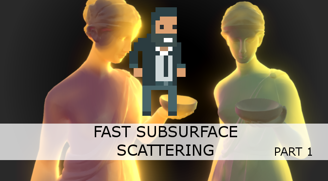
Learn to implement Subsurface Scattering in Unity. This technique is fast and allows to render even more realistic materials such as skin, wax and marble.
Hello! I'm receiving shader errors after upgrading my project to Unity 2021.3.2f1. Not sure how to resolve.

inline float hash2( float2  p, float offset )
{
    p = float2( dot(p,float2(127.1,311.7)), dot(p,float2(269.5,183.3)) );
    return float2(sin(p.y*+offset)*0.5+0.5, cos(p.x*offset)*0.5+0.5);

    //return frac(sin(p)*43758.5453); // original return
}

inline float2 voronoi_noise_randomVector (float2 UV, float offset){
    float2x2 m = float2x2(15.27, 47.63, 99.41, 89.98);
    UV = frac(sin(mul(UV, m)) * 46839.32);
    return float2(sin(UV.y*+offset)*0.5+0.5, cos(UV.x*offset)*0.5+0.5);
}

I'm trying to fix the behaviour of the right Voronoi so that angle of offset acts like the left voronoi
to the best of my knowledge, the above 'hash2' is responsible for generating the random angles
but it does so like that image above
how can I edit it to generate random angles like the left most one?
I tried to sub in my standard random alg, 'voronoi_noise_randomVector' but for some reason that rips the effect appart completely instead of working
hrmgh it WAS ripping it apart, but now when I reverted it to that to show a gif of what I mean by rip apart, now it no longer does anything, angle wont change
WELP its working now and I dont know why
dont know why it tore it appart before and doesnt now, oh well 🔥
What version did you upgrade from?
I upgraded from 2020.1.0f1
Considering that's an experimental version and there's a massive leap between the two I don't think that's realistically salvageable
Unless someone has better ideas I'd recommend starting a fresh project and importing your assets as unitypackages
Also, why not newest 2021.3.?
I released a new mobile game on 2021.3.2f1 and already had it installed and working
Didn't realize how big of a jump it would be. I know the old version I was working with wasn't LTS so I wanted something newer and stable
The project is actually fine, it's just when I build to my Android phone that I'm getting these shader errors
I deleted the shader asset and reimported everything and reconverted to URP
Doing a full overhaul so I can keep my game. I'm not abandoning it
I got it to build! Just have to reconfigure a bunch of prefabs to use the shader
What an absolute nightmare that was
It could've been just a URP incompatibility as well
Everything went from curved to flat. When I checked the prefabs they said "missing keywords" and there was a button to update shader. I updated and it went back to curved. Going to try and build again and wish for the best lol
Yeah I think it was just a build issue or compatibility issue thankfully
Issue is fixed! Thanks
ssr reflection is not working in this billboard shader how can i solve this problem

For SSR to work the billboard needs to write in the depth buffer
Try adding ZWrite On ZTest LEqual Cull Back in the first pass
i am new in shaders can you write this for me is this shader file
Try to add it at line 32, bellow Cull Back

like this
yes
ok let me try
still same
IDK what's happing in the files included in this shader, but I can 100% confirm that the issue is that it need to be rendererd in the depth buffer.
Shader "TF/Cylindrical"
{
Properties
{
_MainTex ("Base (RGB)", 2D) = "white" {}
_Bump ("Bump (RGB)", 2D) = "white" {}
_ShadowTex ("Shadow (RGB)", 2D) = "white" {}
_Cutout ("Cutout", Range(0,1)) = 0.5
_SaturationRandomize ("Saturation randomize", Range(0,1)) = 0.5
_BrightnessRandomize ("Brightness randomize", Range(0,1)) = 0.5
_Ambient ("Ambient Color", Color) = (.5,.5,.5,1)
_LightMult ("Light multiplier", FLOAT) = 1.0
_Speed("Speed",Range(0.1,4)) = 1
_Amount("Amount", Range(0.1,10)) = 3
_Distance("Distance", Range( 0, 2 )) = 0.3
}
SubShader
{
    Tags {"Queue"="Transparent-2"   "IgnoreProjector"="True" "RenderType"="Opaque"}


    Pass
    {
        Tags { "LightMode" = "Always" }
ZWrite On ZTest LEqual Cull Back
        CGPROGRAM

        #include "UnityCG.cginc"
        #pragma vertex vert
        #pragma fragment frag
        #pragma multi_compile_fog
        #pragma exclude_renderers xbox360

        #define TF_CYLINDRICAL_MODE

        #include "tf.cginc"

        ENDCG
    } // pass

    Pass
    {
        Name "ShadowCaster"
        Tags { "LightMode" = "ShadowCaster" }
        Fog {Mode Off}
        ZWrite On ZTest LEqual Cull Back
        Offset 1, 1

        CGPROGRAM
        #pragma vertex vert
        #pragma fragment frag
        #pragma multi_compile_shadowcaster
        #pragma fragmentoption ARB_precision_hint_fastest
        #include "UnityCG.cginc"
        #pragma exclude_renderers xbox360

        #define TF_SHADOW_TEXTURE _ShadowTex

        #include "tfShadow.cginc"

        ENDCG
    }
} // subshader
}
this shader make transparent image billboard shader trees
Does anyone know how to lerp 2 colors together with a gradient? As an example; I'd like one color to be green, the other color to be red, and then transition them with a gradient. So the top of the output node would be red, the bottom green, and then a blend between the two in the middle. I tried using a Lerp with a Sample Gradient (black to white), but the time only blends the gradient into a solid color. I could use a gradent image I suppose, but I wanted to see if there was another way. Thanks!
Lerp is exactly how to transition from one color to another
But I need a node to blend them together smoothly.
As Praetor mentioned, Lerp is what you want. To adjust the transition you just need to remap the T input, easiest way to do that is through a Smoothstep, (or Inverse Lerp & Saturate).
e.g. Here using G channel of UV to obtain a vertical gradient across the mesh uvs, Smoothstep to remap, then Lerp to apply colours

Lerp is said node, it's just a matter of using an appropriate t in the appropriate place
These settings only affect how the model is imported. If it was flat to begin with, the imported/generated normals would all likely be (0,1,0) pointing upwards (in object space that is)
Displacing the vertex positions in the shader will not affect the normal vectors. You would need to manually calculate them. Using an Add node like you have done here isn't correct, you would need to "simulate" multiple positions by offsetting the Position node with the Tangent and Bitangent vectors, then displace them using the same calculation. Take the difference (subtract) the displaced position you have and take the cross product. Example here : https://www.ronja-tutorials.com/post/015-wobble-displacement/ (though it's shader code, not graph).
An alternative to obtain flat shaded normals, is to use a cross product on the partial derivates (DDX and DDY) on the displaced position for the fragment Normal (Object Space) port - would need to change your space in the Graph Settings. Might be easier.

Oh, the question was deleted :\ (oh well! hope that helps someone)
Thanks very much!
So I've been playing around with post-processing, and it's fine and dandy, but I'm having a lot of difficult with the camera stacking in the URP. So reading around it seems that just applying the effects to shaders is ideal, so that's probably what I want to do for all my vfx stuff. However, I can't seem to quite get the effect of the bloom that pp applies, even messing around with the emission and nodes like fresnel I can't achieve that extra glow that I want. Any idea what I should be looking into?

It looks like the bloom is working in scene view, but not in game? Maybe check the "Post Processing" tickbox on the camera(s)
Oh, I've it off purposely to mess around and compare shaders
also turns out the vfx decal node doesnt support shaders right now for some reason x_x
oh yeah that's a complete bummer. I guess camera layering it is
Hey does anyone know how to make a shader graph that automatically paints textures on the terrain
forward decals oh, sorry for ping thought I read vfx graph
im having trouble getting the screenposition
I just want some lines based on where on the screen a given pixel is
it works with orthographic camera but not perspective


Pls i need help in understanding this... Am using an asset called "Toony colors pro" am trying to enable outline in a URP project but i can't understand the process

You need to do the "perspective divide" step to obtain the final screen position. In the fragment shader you'd typically do float2 screenPos = i.screenPos.xy / i.screenPos.w;, can then use that screenPos.x in your calculation.
ty !
As that image is saying, you need to add the RenderObjects feature to the Forward/Universal Renderer Asset. It'll be in your Assets folder somewhere. If you used the URP template, under there is multiple under "Assets/Settings", one for each quality setting.
See https://docs.unity3d.com/Packages/com.unity.render-pipelines.universal@10.1/manual/urp-renderer-feature-how-to-add.html
Configure the feature to use the settings as shown in that screenshot.
If you need further help, #archived-urp may be a better suited channel.
How would I get the colour of pixels behind an object?
I'm trying to create a distortion shader with screen color but the result is much brighter than the scene's actual color
Hey everyone.
Is there anyone that can nudge me the right way how to create this kind of shader:
https://www.shadertoy.com/view/MlVGDK
But i would like to have a hexagon pattern that is distorted and moving like it has a water kind of shader distorting it.
Most tuts ive seen just scrolls the shader. how can i add a voronoi kind of effect to a hexagon texture pattern to get this kind of effect?
thanx


ive played around with voronoi noise, but it isnt distorting the texture.
how to increase spacing between textures repeating it self?

this is made by muving UV by time, but I want the space between Texture talk area and next talk area to be bigger, like to skip one or two repeats
I could create super long texture, but that would jsut waste texture size

i just want to increse the spacing horizontaly between
Adjusting the texture is probably gonna be the easiest solution
that is true.... but I want to learn how to control textures more. Like Want to move them up or down. left or righgt, increase spacing and etc.
another question, textures always needs to be square right?
You can do that by just adding offset to the uvs, but there's no easy way to "skip" sampling the texture. It would involve some math and some kind of dirty solution(like sampling a different texture or this texture at position where nothing is drawn).
The "increase spacing" thing is the problematic one.
No. It doesn't have to be.
but then in order to solve that with texture I should create Huge texture with super small text inside x.x that also makes no sense X.x
when I try to sample the texture that is not squere it gives me wierd results.
lets say the image I have above. I would like to have spacing of 5x. so if resolution of texture is 256x256 then it must become 5x bigger.
Yeah
2.5x actually
Well, you could try the other solution too
If the scrolled uvs are not in certain range set them to 0 0 or something. Assuming the left bottom corner of your texture is transparent, it should work.
You'll have to figure out how to check the range though.
I was tihnking using bool, if something is correct then multiply from sothing that hides the uv, but then in the end it just blinking :DDDDD I used the increasing texture... resolution sucks..... size of texture sucks... but oh well

is there a way to make a material transparent, but have the transparency not be recurrent? (like see through, but you cant see through it more than once)
Have two materials on it. After seeing it once change material. But that will be more raycsasting rather than shaders.
hi! sorry very new to unity, its an incredibly basic question but i've been through maybe 5 youtube videos and 10 documentation pages before trying here and nothing helped
i'm trying to export a model from blender to unity with its materials. from blender, I removed all the non unity nodes like one guide said, exported as fbx etc. the materials are not working in unity, so i'm just trying to find a way to open the shader graph in unity to try to reconnect the texture maps etc
i've just not been able to open the shader graph to touch the materials in unity so far. it is added to the scene through package manager but materials just won't open, even creating new unlight graph
tldr - i installed shader graph but can't manage to open any shaders
the build in shaders are not shader graph shaders
you can make your own and use them in the materials used on the object
with shadergraph you are making / editing shader graphs not materials
oh alright so theses will just not open for unity

i dont mind remaking all of them i just want to get it to work
that not a shader graph
right ok
you can make one via the create asset menu
(or right click in the project window)
alright this is going to be super weird, and i think it's because of something i fucked up earlier but opening a new unlit shader opens the unity hub (i didn't have shader graph actually installed, the default software to open .shader files changed, and i've yet to find a way to fix it) fixed finally
instead of opening the shader
is there another way to open the shader graph that isn't opening a shader 
finally oh god 

you can distort it by adding noise to the UVs before passing it into the texture sampler
What is the difference between Graphics.RenderMeshInstanced vs. Graphics.DrawMeshInstancedIndirect? I'm essentially asking what is the difference between drawing and rendering?
SHouldn't you compare RenderMeshInstanced and DrawMeshInstanced?
is there a better / more efficient way to get a more densely packed voronoi?

doing a single voronoi alone with a higher cell density doesn't have the same appearance

feeding a voronoi into a voronoi sorta works but ist still using 3 voronois and 3 powers 🤔

better question maybe is do I even want a denser voronoi, it looks kinda bad when the object is distant

Sure. I was just trying to understand the difference between render and draw. What is the difference between RenderMeshInstanced and DrawMeshInstanced?
Unity just renamed all the Draw... functions to start with Render, the Draw... functions will be deprecated in the future. At the same time they streamlined the naming and added some new features that didnt exist when Draw... functions were made like motion vectors. They are the same (the declaration forms may differ a bit tho)
Thank you!
x/y question, my real question is how to replicate sparkles of this density

aliasing goes brrr
yeah
maybe I should use a texture of dots? because im pretty sure if it was a texture the mipmaps or whatever will solve that
Yeah a texture would work
yeah no jank if I use a texture

Is it that simple?
If you just want to distort the hexagons, you need to change what you're using to sample the texture, eg by adding some noise to the UVs.
I'm trying to use a post-transparents camera color blitted texture on an object and I can't get that object to not be included as one of the objects that render pre-blit.
is there a "proper" way to do this in URP?
I'm getting this:

the cylinder (as it appeared in the last frame, actually) appears inside of itself
does unity have a getter for numGPUcores?
Could anyone help me please?


i believe it should be SV_POSITION, rather than SV_POSITION0, but i'm not 100% sure
Lemme check it out, Thanks!
IT WORKED! THANKS AGAIN!!
you bet 😄
hello again
trying to make the underwater fog effect now, which from previous research seems must be a URP Renderer Feature Full Screen post processing effect.... i think.
this is my first attempt at the underwater fog effect... which i basically copy-pasted the screen depth part from the URP Water Shader unity video tutorial

effect off:

effect on

it does seem to be doing something though; if i zoom in close to terrain ground it looks like this

ahh the variable inputs, lemme set them up...
Ok, ill give it a try. But i think i already tried it and failed. Im using urp. Which input in the master node should i use to make it happen? The regular basemap?
Base color yes
Ill show you the shader layout later. If im running into problems that is. Otherwise, thanx 🙂
why does this post-processing shader block all the textures? i want to have the underwater fog effect, but i also need the regular terrain textures to show
Hello everybody!
Does anybody know how to fix the noise, so it doesnt get "flat" from time to time? Its done with shader graph and i followed a tutorial. Im not really familiar with it
Thanks in advance!
Thats because your shader graph is flawed, its really that easy
Thanks for answering. I dont know where the flaw would be. Could you direct me in a direction?
In the shader graph of course
Hello friends and neighbors. Can you help me find the words to Google for the following effect? What I would like is a box with one face missing. The missing face is facing the camera. I would like the backfaces (here shown in red) to not render. But I would still like them to occlude the pixels behind them, effectively making the red pixels transparent, but ALSO any blue pixels that fall behind the red pixels. Is there a word or approach that I can search for? Some things that come to mind are portal rendering, but the ensuing camera wouldn't have to be in a different location.

@hearty basin Like parallax interiors?
Why yes, I believe so.

I've been fascinated by technique used on the windows in Marvel's Spider-Man and Forza Horizon 4 so I set out to learn how these games achieved the effect and to see if I could build an Interior Mapping Shader myself using Shader Graph in Unity. Here's how it went...
Flexible Grids: https://www.youtube.com/watch?v=CGsEJToeXmA
Making UI Look Go...
Yep. I was just about to say there are some tutorials on YouTube to help you out.
Thanks so much!
No problem
Hmm except that approach uses a static texture. I need the area inside the box to be interactive...
what could I do to display a cone given an origin, direction, and a vector representing the slope?
I was thinking like some sort of post processing effect, but i'm not sure
it can be dynamic if you render to the texture you use for this effect
but obviously it's not exactly standard
Now I am looking into hole shaders. Getting closer
Could look into Stencils. You'd render the quad (missing face) to the stencil buffer, and then render the cube interior testing against it.
https://docs.unity3d.com/Manual/SL-Stencil.html
https://www.ronja-tutorials.com/post/022-stencil-buffers/
Yep, there it is. I knew I'd seen this problem solved
basically portals
I haven't used these newer versions of URP, but apparently there's a URP Sample Buffer node where you can sample the "BlitSource" which would contain the camera view. The idea is that you then modify that (e.g. apply your underwater fog, probably using a Lerp), then output to Base Color.
And here it is in URP: https://www.youtube.com/watch?v=EzM8LGzMjmc&t=29s&ab_channel=DanielIlett. Thanks all
Here's hoping I can send a ray into that stencil 😐
Probably also don't want to use the "depth difference" here. The A component of the Raw Screen Position isn't something you'd use in Fullscreen effects, only in shaders on objects/renderers (it obtains the depth to the fragment).
Just the Scene Depth should help with producing a fog effect.
If you use the URP Sample Buffer node, probably not. Using a blend mode might allow you to overlay the fog effect without it, but IDK
I dont get it. I dont seem to have the problem when i use simple noise. but with the gradient noise it cycles to back to 0... My Gradient Noise is setup like in the screenshot and goes to the Y of the vertex output

where do i fit in the URP Sample Buffer with BlitSource in my shader graph above?
also i should probably clarify; currently this fog is applying to the entire scene, but next step i'm hoping to limit it to only apply to under water level which in my case is a static flat Y world position (i dont have waves)
Probably something like : Lerp between the BlitSource and FogColour, with the T input set to the Scene Depth (eye mode).
so should i cut out this whole part?

Yeah you wouldn't use that in a fullscreen effect
k removing...
i already have a Lerp going on in my current shader graph, should i leave that one as is? add another lerp before it / after it?
In order to get the world position you'd need to reconstruct it from the depth buffer. I typically use something like this : https://www.cyanilux.com/tutorials/depth/#blit-perspective
(Though I always use it with a custom blit, not the new Fullscreen graph stuff)
"the graph should also be set to use Transparent surface mode for the node to function correctly" doesnt seem like i have that Transparent option in this version of unity / URP.... 😬
That's because I typically use the Unlit graph template. The Fullscreen graph is new, and probably doesn't need Transparent surface mode.
ah ok
resuming trying to parse & figure out this 👆 & linked page...
i should also remove this multiply too then?... so sorry i'm rather new to shader stuff and mostly succeed with step by step directions... 😬 🤦♂️

am i doing this right? where should this connect to / from..

i think i found the "problem"? Is that the normal behavior of the gradient noise? i just added two gradient noises and offset the time a bit and now it doesnt go flat all at once... is that the correct way or can i achieve it with only one gradient noise?
hmm i might be getting somewhere here?.... i hope?....

- do my nodes look sane? do i have any extra / nonsensical / unnecessary nodes there for what i'm trying to achieve?
- how do i make it always at least a bit foggy, it should never be this clear near the viewing camera
- next step - how to do that limit at world Y coordinate so it only happens underwater
looks fine to me, for 2) you can swap the 0 in the clamp for 0.2 or something, or add some small value before clamping
for 3, there's a step function, so maybe multiply the stuff going into the lerp T node by step(-world space camera position.y)
i tried this and it went horribly wrong. what im trying to do is kind of making a heatwave shader that distorts a hexagon pattern. its kind of a forcefield that needs some movement on that hexagon. and im very certain that i want a voronoi pattern, cus its that kind of movement noice, but it should move the hexagon pattern. what i got now is nowhere close to that.
If i follow a heatwave tutorial, is there a way for you to show me where i should put the hexagon pattern for it to be effected of the heatwave distortion?
What did you get?
this is what i got


Multiply the voronoi noise by something small and put it in the offset node, leave the UV in the UV node
(those circles are because the voronoi is swizzled to 2D, so you end up just sampling a diagonal line across your texture, where how far along the line you are is determined by the distance from the nearest point generating the voronoi)
what did you mean by leave the UV in the UV node?
most definetly it.
It's in there by default, just pull out the voronoi and put it into the offset instead
ok, we have something going then. but the patterns is all over the place. its moving around, but it is getting distorted. and this with a small number.
think i got it. i had to decrease the multiply on the second multiply
its like water moving now.
think im gonna see if it works overall with the rest of the stuff. thank you alot for this.

Hey, is it possible to make lightning branch out in a single shader pass, or does that require multiple billboards/passes or animation to make that effect?
Im trying to use a 3d texture in a custom node but I cant figure out what it wants in
Samples a 3D texture.
this method is being called
it says the in is a Sampler3D
but how do I pass that in? what is that? its not in the dropdown of types

which of these is Sampler3D?
How do I substitute or create a Sampler3D if none of them are?
im trying to make that line work
How do I resolve the error: "Too few arguments to a macro call"
float4 sampledColor = SAMPLE_TEXTURE3D(_MainTex, SS, (samplePosition + float3(0.5f, 0.5f, 0.5f));
this line has too few arguments but that method only takes in 3 arguments
so I dont understand how its too few
float4 _SampleTexture3D_Out = SAMPLE_TEXTURE3D(Texture, Sampler, UV)
what am I doing wrong? whats different that makes mine too few but theirs not too few?
How do I replace this? How do I fix this? How do I sample a 3d texture???

it says the error is happening at line 21
but line 21 is just a bracket
why am I getting all these errors, why is nothing working
cannot convert from 3d texture to 3d texture????? that makes no fuckin sense
'SAMPLE_TEXTURE3D': Too few arguments to a macro call
': 'tex3D': cannot implicitly convert from 'Texture3D<float4>' to 'struct UnityTexture3D```How do I solve these 3 errors? google has zero answers
I got the code fro mhere but it doesnt work or do anytrhing
getting fed up, time to quit workng because there's no help on right now and no help in google either
hello, I was hoping someone could give me insight on how I might correct this issue.
img1: working correctly. single texture import.
img2: spritesheet texture.


it seems when its a spritesheet, the sample uses the whole texture and not the sprite's texture location.
It's actually the opposite. When using a single texture the UVs range from 0 to 1. But when using a sprite sheet the UVs stored in the sprite mesh is a portion of that texture. That's why only the wizard-cat is displayed here, not the entire texture.
I assume there's some polar coordinates stuff going on here for the swirl & outline masking, but for the sprite sheet a value of (0.5, 0.5) is no longer the center! And there's some scaling differences.
If you pass some info from the SpriteRenderer to the material, it's possible to convert the sprite coordinates back to a 0-1 range. The answer here might help with that : https://stackoverflow.com/questions/53820303/how-to-get-original-texture-from-spriteatlas-to-use-in-a-shader-as-alpha-mask (though may want sprite.rect in this case rather than sprite.textureRect?)
that makes sense. so i need to pass the origin into the mat
relative to the sprite.rect
thank you @regal stag
In SG v10.3+ (Unity 2020.2.3f1+) you need to use the "Bare Texture 3D" and "Bare Sampler State" on the dropdown for the port types if you use Texture3D and SamplerState in the code parameters.
When using the "Texture 3D" type you can instead use a UnityTexture3D type as an input, which also provides the sampler associated with the texture via .samplerstate.
float4 sampledColor = SAMPLE_TEXTURE3D(_MainTex, _MainTex.samplerstate, (samplePosition + float3(0.5f, 0.5f, 0.5f));
In this case you don't need the SS input. But if you wanted to be able to override the sampler you would use the UnitySamplerState type for the input.
If you need to sample in the vertex stage, you would use SAMPLE_TEXTURE3D_LOD instead, which has an additional lod param.
Could anyone help me?


I'd you're using some of the unity stuff, you need to include the correct files that define it. Do you include anything?
Not really
Did you write that shader?
i grabbed it from some open source game
Well, then it's gonna be pretty hard to troubleshoot it...
😦
What render pipeline are you using?
Like you mean render pipeline package?
Yes.
I got lightweight one
Oh
Anyways, the shader is for built-in rp.
Okay
Okay, thank you
Is there a reason that my texture preview (in the inspector) looks so dark/faded while the preview in shadergraph looks normal? Really weird behaviour. The texture is a single channel one.

If I set the alpa source to 'from grayscale' it looks good but that's not really the intended behaviour since I have explicitly set the alpha values of the texture.

im trying to find a shader on store that i swear i saw someone do, where it makes it seem like it "combines the meshes" by blending or something, does anyone know what its called or where can i find something like that
Hi! Im looking to upgrade from built in to URP because URP has some features and new resources that i find very useful and are no available in built in.
My question is, most people complain about URP being not stable enough, what are your thoughts on this?
Also, do quality or performance actually improve from built in to URP?
Im learning shadergraph and most resources use URP, also Render Objects is a very useful feature.
Maybe the texture inspector is turning the single channel into RGBA, and then it's applying it onto a black background so you're effectively seeing the alpha squared (one from transparency to black, one from grayscale)
Might be it! It does not really matter that much really, the texture is usable
Not sure if this is the best place to ask this.
I'm trying to make a game object that is a disappearing hoof print.
I'm using the time node to affect transparency and make it disappear. But time makes it so once one object is spawned and it runs, it won't appear on new game objects.
Since the material is being used by all game objects I'm assuming that's the problem, but I'm not sure if I'm trying to make shaders do something they can't, or I'm missing something in the shader graph


I think the time node runs from the time when the scene starts; try adding a property for the time the object is created (set through a script) and then subtract that from the time
The line of code you put in has an error. Too few arguments to a macro call
float4 sampledColor = SAMPLE_TEXTURE3D(_MainTex, _MainTex.samplerstate, (samplePosition + float3(0.5f, 0.5f, 0.5f));
passing in UnityTexture3D and using it doesnt work
Would I be able to get the shader properties and set them in a C# script, or would that need to be through HLSL?

Yes you can set shader properties through C# scripts; that's what you're doing if you set the color of a material for example.
    // Start raymarching at the front surface of the object
    float3 rayOrigin = i.objectVertex;
    // Use vector from camera to object surface to get ray direction
    float3 rayDirection = mul(unity_WorldToObject, float4(normalize(i.vectorToSurface), 1));
What are these vec3 in the context of shadergraph? how do I pass them in / generate them?
I dont know what i.objectVertex is, or i.VectorToSurface
is it possible to use shader graphs in build in render pipeline?
I think so? (Though if you're using existing shader graphs you'll need to change it in the graph inspector)
objectVertex looks like the fragment position in object space, and rayDirection is the normalized object space view direction. (or maybe view direction negated)
Like this?

I believe so

hm its outputting something but that something definitely isnt a volumetric perlin noise

fixed the black top by changing the position size, but its still opaque 🤔
void RaymarchTest_float(texture3D _MainTex, SamplerState SS,  float _Alpha, float3 rayOrigin, float3 rayDirection, float _StepSize, out float3 Out, out float4 OutColor)
{
    float EPSILON = 0.00001f;
    float4 color = float4(0, 0, 0, 0);
    float3 samplePosition = rayOrigin;

    if(max(abs(samplePosition.x), max(abs(samplePosition.y), abs(samplePosition.z))) < 0.5f + EPSILON)
    {
        float4 sampledColor = SAMPLE_TEXTURE3D(_MainTex, SS, samplePosition + float3(0.5f, 0.5f, 0.5f));
        sampledColor.a *= _Alpha;
        color = BlendUnder(color, sampledColor);
        samplePosition += rayDirection * _StepSize;
    }

    Out = samplePosition;
    OutColor = color;
}```Can you see why its not building up?
its not volumetric, its just surface

This actually helped a ton. I'm now able to restart that timer with the press of a button.But it seems all spawned game objects are still using the same shader. So when I restart the timer on one, all of them do it at the same time.
It looks like you're only taking one step? Edit: No steps, even
There's no loop
Are you accessing the material by sharedMaterial? (SharedMaterial is shared across all objects using that material, whereas material is just for the one mesh)
oh yeah 🤔 ill go back to the source code and see what they had as a loop
It should just be adding the direction multiplied by jump size onto the position, then sampling again, and looping until you leave the cube or hit some max number of steps
I understood the first part but I'm not sure what I do with the dir * jump after I have it

they are adding 0.5 onto a ton of things for reasons I dont know
Just add onto the position.
The 0.5 seems to be transforming between a 1x1x1 cube with the origin at the center (for the object space positions) and a 1x1x1 cube with the origin at the corner (for sampling the texture)
(In the if(), the 0.5 is to check whether the position is outside the cube)
float4 sampledColor = SAMPLE_TEXTURE3D(_MainTex, SS, samplePosition + float3(0.5f, 0.5f, 0.5f) + addedDir);
Add it like this?
Because nothing changed visually when I did this
I also noticed that inside the loop its doing
samplePosition += rayDirection * _StepSize;
so wasnt it already adding that before I just did?
and it wasnt working before either
In each iteration, add the jump onto sampleposition, so it keeps marching along in the direction of the ray
is that not what that is?
That was it, I was creating a material and dragging it in the inspector. I had to get the material from the renderer and that fixed it. Thank you so much!
In here there's no loop

there there is, in the code block earlier there wasn't
You're looping until it reaches _StepSize, instead do 1.8/_StepSize (since the diagonal of a 1x1x1 cube is ~1.7 something units iirc, and you want all your rays to march all the way across
oh sorry I added the loop after you told me to but didnt update the posted code
i added a max size and now it ray marches but it does it only when step size is negative and it looks janky when rotated 🤔

ill try this now
You could also use what you did earlier with the refraction stuff to get the depth through the cube, and instead of sampling at regular distance intervals (which will give you lines like that, unless the intervals are very small) you sample at regular percentage intervals along the ray through the cube
Doesn't work as well when the cube is almost opaque, but works better if you're doing fewer steps
Negative step size is probably bc i got the sign wrong on the view direction

I was trying something with that but couldnt get anywhere with it
I think this is a dead end though, the raymarch version looks pretty awful and because the 3d texture has to be passed in unsampled, I cant do anything to make it look less bad
im trying to do volumetric effects inside the dice

It should look less awful if instead of sampling at regular distance intervals you sample n times through the entire distance across the cube, but those n samples have different distances associated with them
it doesnt have to be a texture 3d, but everything ive tried that isnt raymarching looks awful or inconsistent
(Though also if you make step size very small it would work and look OK)
(if expensive)
yeah expensive is the problem
there will be many of this so I dont want it to be heavy
is there some non raymarching way to emulate having interiors like that? probably not?
my problem with multiple paralax planes of noise is that there is no way to keep it consistent across different angles
the interior looks completely different depending on which angle you look at it from
Are decals useless? They cannot be made to draw before custom render object passes ?
https://www.shadertoy.com/view/ftVfWK @tight phoenix
(here the texture is 32x32 so i made small steps (128 of them) but for a lower resolution noise you could do much fewer steps)
Link appears to be broken 🤔

Right, my fault (had it set to private). Should work now
working now 👍
Also I modified it to only take a small part of the texture (8x8x8) and fewer steps (10)
Tbh even at 4 steps it looks volumetric (ig bc the angle isn't changing much due to the refraction)
I am new to unity, this might seem like a stupid question, but is there a way to apply a shader to an entire camera?
Does anyone know what is happening in the "scene" the boxes look fine but then when I'm in "Game" they come out with a black background texture.
I am using a material with a shader to change the color of the object.


@brave kettle
maybe it's sharing a material with something else thats changing the background color
you could try
setting the material on awake
Material mat;
void Awake() {
var sr =  GetComponent<SpriteRenderer>();
mat = new Material(sr.material);
sr.material = mat;
}
ye but the background change the color when restart the unity idk that happens
Post processing shaders?
heya, i'm new to shaders and am just doing random challenges to learn. Does anyone have any better ideas for a sprite outline tracing effect?

here i'm doing polar coordinates and rotating a cone
but the right one isn't looking as good because it's not a circular shape
any better ideas?
i just try this other time but dont wor, what do u recommend me?
sorry thats the best idea I have. Why does it need a material? can't you just use sprite-default?
because i have shaders to change border colors and other colors like this (the first item havent material)

my material have this colors but i dont have this red baackround in nothing

does anyone know how I can create a camera shader that will color an object based of it's emission color
ie If emission color was pure white the object would be entirely white (unlit)
What is best practice for passing an array of structs (or just floats) to Unity's Shadergraph?
Is there a way I can modify vertex data and have it persist into another shader or pass?
kinda of like a rendertexture but for vertex data?
I have an animated texture and a texture mask, how do I combine the two such that the animated texture gets erased by the texture mask?
Still of the animated texture in question

The texture mask

You guys have a good resource for maps?
Things like distortion textures and all that.
Black and white stuff.
Tile-able.
is there a way to exclude an object from shading?
trying to do #3 now.... 🤔
what needs to go into Edge, In ?

in is whatever you want to clamp, edge is the value it will cut off at
I don't have enough experience to say
if it was me I would try different values for edge to see what result I get and figure it out from there
i'm not even sure if Edge is supposed to be the static value (ex. 100) and the In the camera world position, or vice versa
The Step function returns 1 and 0, white and black
the edge value determines where that cutoff originates
ok
if you pass in a UV node into In, and set edge to 0.5, you'll get exactly 50% white and 50% black
so i'm guessing Edge should be the 100 and In should be the camera pos Y
Maybe, I don't know your use case, I just know how the node works
cool thanks lemme try
question about 'Distance' in shaders 🤔
I know that distance is a float, a measurement of distance between two points
But what does distance mean for a fragment shader? What is being measured against what distance wise?
if I pass in object position, 'distance' from that seems to be measured by the 0,0,0 coordinate if I understand it correctly
Is each individual pixel fragment measuring its distance away from something? How does it know where to measure against based on the other vec3 input?
like a vector 3 can be a single point, but it can also be more than a single point
distance takes two inputs?
yes? I dont know why you are posing it like a question
length takes one, distance takes two
Because I don't understand your question, you pass it two coordinates and it returns the distance between them
my question is I can pass in a vector 3 that is 3 arbitrary float values, like a color, and a vector3 that is a coordinate, how is it measuring distance between vec3 at the fragment level
bump
passing in an object position vs passing in a vec3 that is 3 random numbers
(b - a). magnitude
Why does it matter what space a and b are in, they're numbers
If you're getting the distance between a colour and a screen position that's still just the distance between two float3/4s, what they are doesn't matter
a position node is not 'just a number'
its many numbers?
how does it know what number is the number to measure against?
It's a vector
nevermind, you clearly don't understand my question
i'm in need of an answer on this, i need a shader to shade every object on the screen except for two sprites
What does shading mean?
If you want to make something invisible put it on a layer not rendered by your camera
activate on the object i guess, i have a chromatic abberration shader that i want to work on every object on the screen except for two sprites
not invisible, just not affected by the shader
If it's a post processing shader then you either need to render the object after post processing, or write a complex setup that punches a hole out of the post effect using a buffer or stencil mask.
None of it is really that simple and depends on the render pipeline
OK this is what i ended up with so far (added the highlighted nodes) and it seems to work as described; the shader has no effect when camera is above the position i set in Edge, and it does show its effect when below, which is quite nifty 👍

(still have a few questions, like why does it only work if i use a negate node and negative Edge value, however if i remove the Negate node and try using positive Edge it does not)
but mainly: I realize my requirements goal posts have shifted 😛 the effect i'm after should work even in "split screen" i.e. even when camera near plane is partially above Y 100 and partially beneath Y 100, i.o.w. i need the shader to perform its effect "on all pixels which belong to areas beneath world Y coordinate 100" no matter where the camera viewing angle is positioned from/to. Whereas currently if the camera is at a position above world Y 100 but the camera near-plane is still partially dunked underwater - there is no underwater fog which looks not good (and theoretically if the camera position is beneath Y 100 but still near-plane peeks out above water partially, it might still render the full effect even above water - altho i havent seen this happen currently)
Perhaps try to describe it better, because it's getting the distance between the two inputs. It doesn't matter if they're a float, float2, float3, float4.
It'll just be distance in 1d, 2d, 3d, 4d.
float distance(float3 pt1, float3 pt2)
{
  float3 v = vt2 - pt1;
  return sqrt(dot(v,v));
}```
Is what a float3 distance function might look like.
A position is a float3, the function doesn't care what space it's in, what it is semantically. It's essentially the same as 3 random numbers making up a vector as far as the function is concerned.
If your question is about how things are interpolated as they enter the fragment shader, then that's a problem unrelated to distance. If your question is about passing mismatched dimensions into the function, like comparing a float with a float3 then I would probably avoid that entirely and swizzle the argument so it's clear what dimension is being compared.
```c
distance(a.xxx, vec3);
distance(a, vec3.x);```back to trying to parse & figure out this idea...
The negate node is because step is 1 for values above the threshold, and 0 below. If you want it to turn on below a certain value, you have to flip it so it's 1 below and 0 above, which you do by negating the input.
You could add camera near plane multiplied by negate(normalized world space view direction) onto the position, then rather than switching if the camera is below or above, it switches when the pixel on the near plane passes below or above.
Good morning!
Anybody familiar with light cookies?
Im trying to use them in URP but Unlit shaders dont support it.
Any workaround for this?
Thanks!
can someone help me? how would i pixelise the dither output?

i can pixelise a texture with the pixelise group but im not sure how to do it to the generated shader
You want to pixelate it at the start, so you sample pixels of noise. Rather than using the position, you can use the pixelated UV to sample the noise
i got it thanks
now i need to make it not scale when you resize the object and not move when you move the object

do i just do that by chaning the uv to position?
Wait you want it to stay in the same position on the screen?
yes
yea that changes on y axis doesnt it?
yeah so if you move the object around the gradient will follow
then no i would like the whole thing to stay still
Take the screen position and use that instead of the UV, and it should work

You could try just adding a property in the shader graph, calling it _MainTex and then seeing if it's happy
ok
guys how do i edit the emmission of my custom shader?
i want it to give me the window that it typically opens for HDR color
Guys, can anyone help me with this or have a hint for performance optimization of a shader with several passes, executed via Graphics.Blit?
Unity Forum
I have a shader with multiple passes, where every pass requires some textures and variables which I need to bind from a C# script.
I want to execute...
So that sample shader isn't the "real calcs" right? Right now you're basically averaging everything but blending over top. That just for "discussion purposes" yes? Because I think you could do it all in one pass otherwise. I think...
Try researching MRT (Multiple render targets) as your 2nd pass seems to be copying c to d, whereas you could just output to c and d at the same time in the first pass if the blend would work that is, they'd have to have the same contents to start with.
Or maybe I read it wrongly...flyby. 😉
trying this now - how do you mean do i add it onto the position? this is what I have so far (i removed the previous camera position Step thing - should i not have?)

Add it onto the camera position