
#archived-shaders
1 messages · Page 15 of 1
I wish I knew, but I'm lost. You're doing some sophisticated stuff that I don't do off the top of my head.
I appreciate it
I think where I am going wrong is the method/means by which I round the edges
IF you know those results and can save the rounding so that you know the world space value of the rounded result, you'd know the distance. But how? IDK, I'm frankly not tracking well since others have been helping.
dont worry, ive started over so many times even I'm not tracking it well

and this is version 6 of graphs that big
time to delete all but the most recent and start version 7 🔥

the position node isnt square, its spherical, if you get distance its from its center point
meaning higher distance at the corners than the faces
I... cannot concieve of any possible way to round the edges of that
its not a physical thing with bounds and dimensions, there is nothing to round
when I look at this and say it has rounded edges, what it actually has is that the distance to the center point values are all the same along the faces and the corners alone the distance is longer

Right. But somehow you're rounding the pixels. I haven't de-coded the SG enought to know what you're doing. But you're not using real position at those edges, you're rounding them off to a NEW postion
Yeah im realizing that now as well
the edges arent round, the edges are now a new distance further from the center position

So if you can compute the world-space location value for that pixel you rounded off, and you can take the distance between that pixel and another one in WSpace, you'd have it.
understanding that its not rounded, its just further (or closer?) to the center point makes me understand why im getting these shapes

compute the world-space location value for that pixel you rounded off
Ill have to google how to do that
can the mesh somehow tell me?

Well, you said it has the "same distance to the center" except...
So if you know the center, and can add that distance, don't you know the pos?
I'm talking off the top of my head here.
I also have to hit the shower, going to dinner. Laterz all.
hmm I was subtracting instead of adding, maybe this is the mistake thats cascaded forward this entire time

ill try add
nope adding isnt the answer, that got weirder


hmm
the distance here im seeing is black where the view distance and mesh intersect
black means distance of zero
so.. somehow the distance from the center of the mesh and the surface of the mesh is zero where the view direction is aiming?
god the hardest part of debugging shaders is trying to grasp wtf the color data is trying to tell me
is it a space problem?
maybe I should be doing it all in world instead of object?
doesnt seem to be an improvement


now im even more confused
the distance ffrom position is totally different if I send it in
oh its the normalize doing that

normalize makes a lengh be between 0 and 1 right?
im starting to doubt everything I think I know
-1 and 1 rather?
saturate is 0 to 1
hm looks like the metallic-ness basically exchanged blue-tinted landmass reflections with blue-tinted specular highlights... any way to have both white specular highlights AND colored reflected environment?
also still no success yet with automagic reflection probes.... still trying at it....

yeah im stumped
nothing im doing is getting me any closer

i keep ending up with this shape
literally 7 * 6-7 attempts all coming from different methods, all result in that
i have exhausted everything I can think of, everything I can find on the net, and exhausted anyone able to help me
im starting to think its just not possible
it can't be done, i'd love to be proven wrong but Its just not possible to get the distance of a ray length through a rounded cube
does it make sense that i needed Box Projection? i'm just playing around pushing buttons, and apparently when i enable box projection it seems to automagic
next issue is - previously the reflection looks nice and defined 👆
now i seem to have gotten the dynamic baked Box Projection thingy to work, but now the reflection looks very very mild & washed out.... any known reason why?


could a rounded cube SDF somehow be used for distance purposes?


i have the box and I have the roundedness
but im struggling to combine them to make the upper one rounded
I keep getting results like this

with my different attempts to blend them
hm maybe one of them should be adding and the other subtracting?
subtract middle from top?
doing that gets you bottom
ah right
what if you multiply by some factor, like the roundedness divided by cube size?

how would I do that? what are my roundedness and cube size values?

this value controls roundedness to the best of my knowledge

cube size I have no idea what value that would be
Just see if you can multiply the middle one in your three images by something and subtract from the top, to get something that looks rounded
And then if it works, see if you can rewrite whatever value you get in terms of the parameters you're putting in

that looks pretty rounded
but it only works on that specific value
any more or less and this happens

yeah that looks pretty perfect
Absolutely! Matching it all up precisely might be a challenge, or you could just go full goose bozo SDF showing on a quad. Maybe, but I don't want to redirect you. Then you'd have issues with making sure to update the depth buffer (somehow) and put a collider in the right place if you need one. IDK what you're fully up to, but the exercise is interesting.
it should be like that though because there's only one value where the thing you're subtracting exactly removes the sharp corners; otherwise you either undershoot and still have corners, or you overshoot and your corners are sharp but pointing inwards
you can still see a little bit of an edge there

but its definitely like 95% of the way there now
im already using an SDF for both sides of this so I think matching it up I already have
but I dont have depth buffer
Havent i declared them though?

// Each #kernel tells which function to compile; you can have many kernels
#pragma kernel CSMain
// Create a RenderTexture with enableRandomWrite flag and set it
// with cs.SetTexture
RWTexture2D<float3> Result;
Texture2D BaseMap;
//static const float2 du = {1, 0};
//static const float2 dv = {0, 1};
[numthreads(8,8,1)]
void CSMain (uint3 id : SV_DispatchThreadID)
{
Result[id.xy] = BaseMap[id.xy];
}
like that should be enough to run it right?

I declare this close enough
oh the gif shit itself
no roundedness and 2.5 roundedness


hm I dont know if this is a problem but

5 roundedness is a sphere
IDK why. Maybe review all the settings to see if there's some kind of scalar. But if not, make your own! Make a slider variable and just multiply the color by the scalar before you add it into emission or to the color. (I think you were doing emission...)

but its only a sphere from that precise angle
from straight on, its not a sphere
that's weird
that to me implies something is wrong deeper in the code
Setting a colour works

i'm trying to think of a way that you could create a rounded cube that might lend itself more easily to analytic solutions, i'll tell you if i come up with anything
@tight phoenixAre you using a mesh-cube that is rounded anywhere in all that stuff? You know, like rounding it in the modeling program with lots of polys. I ask because there's a way to get front/back with that.
Im going to go make supper now myself
yes and no, I am using a rounded cube mesh, but all the rendering is based on a cube SDF

not based in any way on the cubes geometry
so the look is identical on a regular cube and on the rounded cube, since the SDF is just treating it like a window, I could throw this on a plane with no difference
And you want distance along the view-ray from the front-side to the back side.
For any pixel?
My end goal is a color value equal to the distance through the cube, where 1 white is corner to corner
but on a rounded cube instead of a perfect cube

getting distance straight through is easy
making it rounded is very not easy
more obvious when converted to 2.2 gamma

OK, you man manually do a 2-pass shader. Render the back faces of the rounded mesh. That updates the depth buffer.
Then in pass 2, render the front faces, and subtract off the values from the depth buffer since they are "in the back" from the front, and that will give you some type of depth....IDK if that's from the near plane of the camera or from the view ray though.
It does have one.
thats not what the internet says when I google it
You might have to hand-write shader though 😦
I have no ability to do that
anyways if its just the back face coordinates you want, I already have that without a second pass

inside out cube uvs
OK, it was just a thought.
There is a scene depth node.
https://docs.unity3d.com/Packages/com.unity.shadergraph@6.9/manual/Scene-Depth-Node.html

gif isnt happy but you can tell what im trying o show off
isnt depth buffer going tob e expensive? id like to avoid it if possible
the mesh isnt transparent and there is no second pass atm
if the whole purpose of the depth pass is just to get the back face coordinates of a cube, i have that alreadyt
Just something to ponder over dinner, bunp.
It's not the coordinates, it's the actual depth. If that's what you mean, cool. You could "just" subtract that from the current front-face pixel depth and you'd know the depth I would think.
Oh, IDK then. I'm lost. Ignore me.

im very lost with compute shaders
I dont know why I cant read any texture information in this one compute shader
yet it is using the same code for accessing the texture that the compute shader that does work is using
its like i need to write the rest of this shader that I have ready to go, but i cant get it out to work
cause it cant read a texture, but its basically identical to the code that can read texture colour
and Ive tested that texture with both shaders
what could be causing a compute shader to read each pixel value in a texture as (0,0,0,0)?
what does your c# side look like? @cursive swift
Anyone know how i access and activate the double-sided bool on a material at runtime?
cant seem to find docs for accessing it
`using System.Collections;
using System.Collections.Generic;
using UnityEngine;
namespace Ustyler
{
public class NormalMapRotation : MonoBehaviour
{
public ComputeShader computeShader;
    public Texture texture;

    public RenderTexture renderTexture;

    public Vector2Int resolution;

    private void Start()
    {
        renderTexture = new RenderTexture(resolution.x, resolution.y, 0,
            RenderTextureFormat.ARGB32);

        renderTexture.enableRandomWrite = true;
        renderTexture.Create();

        computeShader.SetTexture(0, "Result", renderTexture);
        computeShader.SetTexture(0, "BaseMap", texture);
        computeShader.Dispatch(0, renderTexture.width / 8, renderTexture.height / 8, 1);
    }

}
}`
@karmic hatch
I originally was testing my rotation compute shader with it
I have it set now to using my height to normal map compute shader
which atm looks like this:
#pragma kernel CSMain
`// Create a RenderTexture with enableRandomWrite flag and set it
// with cs.SetTexture
RWTexture2D<float4> Result;
Texture2D BaseMap;
[numthreads(8,8,1)]
void CSMain (uint3 id : SV_DispatchThreadID)
{
Result[id.xy] = BaseMap[id.xy];
}`
Tried to strip it into being the simplest possible shader I could with a texture
did that work?
yea
hmm
that one was working great
and my normal map overlay compute shader is working great and still working
and ive given it the same textures Ive been trying to use in this one too just to confirm its not the textures
everything is set correctly in the gameobject running the script?

You need to define the texture type of Texture2D at declaration as you do for the render texture.
Texture2D<float3>
Yep. The shader didn't compile probably. I guess you missed the error. It only shows once I think.
They do?
yea
good spot!
`#pragma kernel BlendNormalMaps
// The target render texture used for normal maps.
//The results of the rendering will be given to this material.
RWTexture2D<float3> Result;
//The base normal map that will have the detail map overlaid ontop of it.
//Set the accent layer to this.
Texture2D BaseMap;
//The detail normal map that will be overlayed onto the base normal map
//Set the fabric material to this
Texture2D DetailMap;
//The blend normal maps function.
//This is the reoiriented normal mapping implementation
[numthreads(8,8,1)]
void BlendNormalMaps (uint3 id : SV_DispatchThreadID)
{
//The write up for this implementation can be found here:
// https://blog.selfshadow.com/publications/blending-in-detail/
float3 t = BaseMap[id.xy].xyz * float3(2, 2, 2) + float3(-1, -1, 0);
float3 u = DetailMap[id.xy].xyz * float3(-2, -2, 2) + float3(1, 1, -1);
float3 r = t * dot(t, u)/t.z - u;

Result[id.xy] = r * 0.5 + 0.5;
}`
Hmmm... Perhaps it uses the texture format by default then?🤔
Yeah, that could be the issue
maybe it could figure out it needed to be a float 3 from that?
Thank you so much for that
cause yea, i had spent a long time testing and trying to figure out why one was working and the other wasnt
I always define my texture types. Didn't actually think it works without it.😅
😅 Im still very new to compute shaders, so since it worked with the other i didnt think twice about it.
Well, we both learned something 👍
Are you sure this one provides the expected result though?🤔
it was yea
though i could have changed it since i started this shader
I wasnt checking if it was producing the correct results
I was only checking then if it was outputting anything
I'll define it with float4 now and test it with normal maps
yup its working as expected
Got the shader working!

though, i did notice following that example code for how unity's height map to normal code works is that the normal map seem to be right.

the blue is very intense compared to a standard normal map
and without some extra processing, the normal map generated looks like that too
unity's normal maps range from -1 to 1 is my understanding instead of 0 to 1, is why the deep blue
ah okay
I might adjust it back then
can thre be a structured buffer as an array? or could i have the elements of the struct be arrays?
Nope
Dang. I might have to rethink how I’m making this last compute shader
My plan was to have a array of them merge with some additional float values to control things like position
Array of what?@cursive swift
oh an array of textures with some additional information
I know the textures are possible to store in an array
and I can store floats in an array too so olong as theyre predefined in length
Well, have some kind of struct to store additional data for each texture, then upload a compute buffer with an array of these structs.
No color related nodes exist ?

Doesn't seem quite right

Oh, there are some😅
Hi,
does URP support scene normal sampling?
If so what shader graph (v12.1.7) params i need to define, and what would be best way to sample it as rgb in custom code node?
Hello i need magician shader 🪄
,,Redcolor outliner'' I have using UVFree shader and put the materials for ramp and cube, ramp have blended because it has an angle of 90 degrees ,,Green outliner'' used standart assets and have blend material with gimp so somebody know or can help me for rebuild UVFree shader and get this same resoult for cube ,,Bluecolor outliner''
https://assetstore.unity.com/packages/vfx/shaders/uv-free-triplanar-shader-pack-23425

Not by default, but you can use a custom renderer feature to create a normal buffer, or for example the AO one already has it.
I'm gonna look into that, thanks
Anyone know if disconnected shadergraph logic is considered during the shader pass ?
basically, is it a performance concern if I have some disconnected heavy-computation shader logic in my shader?
I'm leaving it there, assuming that while disconnected, it is in a quasi-commented-out state. But would love some confirmation if this is in fact the case
Pretty sure if it's not connected it wont be included in the generated shader code. You can view the code to double check (button in inspector on graph asset)
And even if it was, it would be ignored for the compiled version
Thanks for clarifying
what are you trying to do?
i trying to get this smooth textures one to two for borders but my game is tile system then have problem and need to modyfied this shader
,,green outline'' is good because have angle 90 degress, but idk how to doing for ,,redoutline'' ground because it is flat

the angle and the ground blending have nothing to do with eachother
you need to either paint the material with vertex colors for a blended material, or create seams manually
so, by modifying the mesh and the shader if it isn't supported in it
I am just reading and looking for information you say "vertex"

"Polybrush for Unity" enables mesh sculpting and painting inside the Unity editor. Fully compatible with both imported and ProBuilder meshes! www.procore3d.com/polybrush
what are you using for terrain
are you placing the tiles manually?
the map is created in the editor, it is read later from the file
the stuff that loads the tiles needs to make the borders smooth
(along with a shader ofc)
but it needs preparations to work
if that 3d tile managing / building system is an asset talk to it's creator about it
yeah but the textures is automatic continous for next tiles then it is hard work for making all borders
@cosmic prairie but I think it will be it https://www.youtube.com/watch?v=lxTi1vFOObk&t=54s
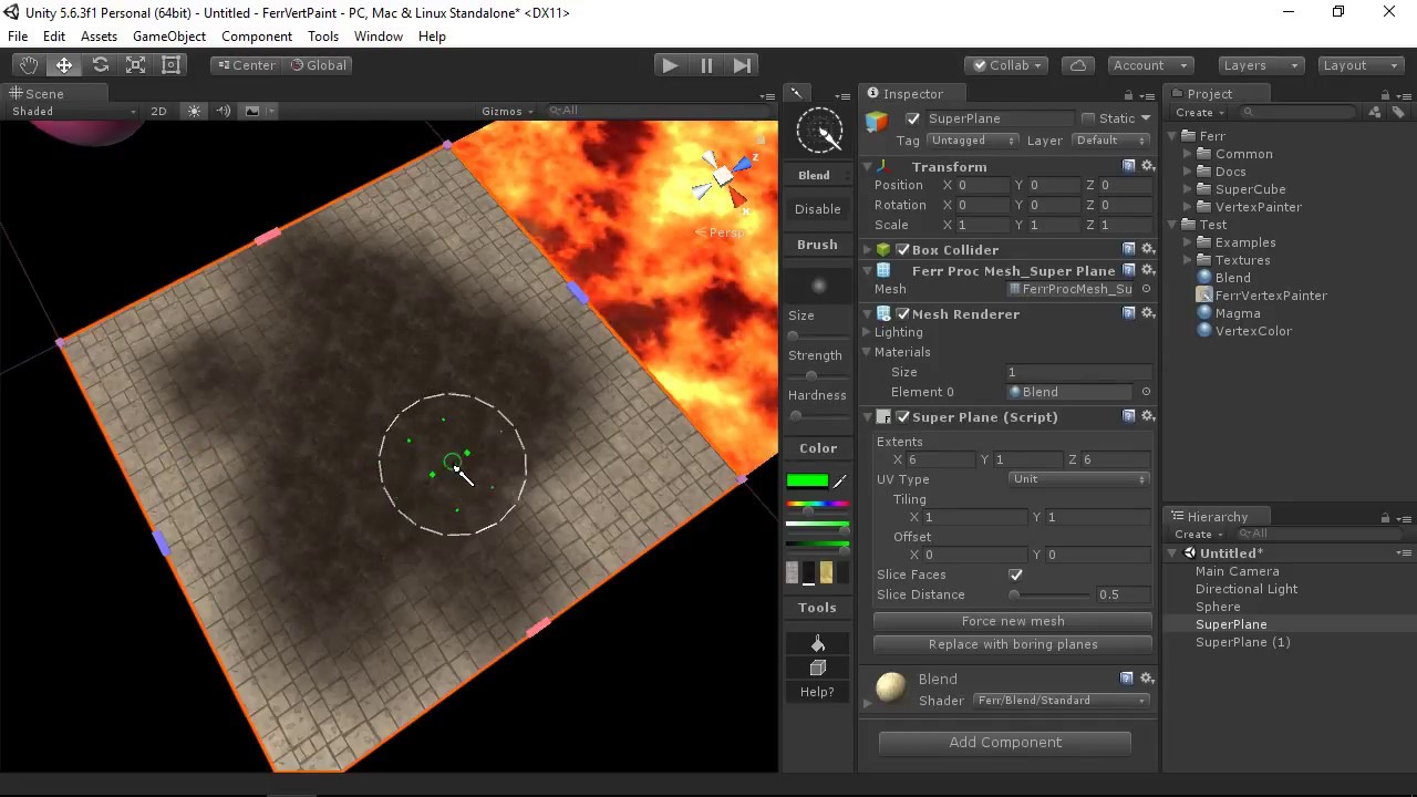
Learn how to paint and work with materials in Ferr Vertex Painter. A quick romp through the shaders that are available, as well as tips on updating your art assets!
Check out more documentation here:
http://ferrlib.com/tool/vertexpainter
Or get it on the Unity Asset store here:
https://www.assetstore.unity3d.com/en/#!/content/100430
Hello, I have an issue related to the Graphics.Blit() function. My situation involves a shader which utilizes an Ellipse node, of which the RGBA values are changed to, say, 1f,1f,1f,0.5f during runtime. When I render the resulting Texture2D, the circle indeed is white and has an alpha of 0.5f. However, when blitting this circle onto my Texture2D (which I call my canvas), instead of drawing a circle with an alpha of 0.5f it takes the circle's alpha and multiplies it by itself (in other words, the alpha of the circle is squared). I am unsure as to why this would happen, which is why I came here to ask for any ideas on why the alpha values would change in such a way. Thank you very much for your time.


the second image is during runtime

_Brush is the Material shown in the first image, whose alpha was proven to be 0.5f through Console
A and B are interchangeable RenderTextures meant to render onto each other so that the Blitting process can actually be done
rtSwitch is what switches these around
CallRender() copies the resulting texture onto the Canvas, known as C

I'm thinking I probably missed a rule about Graphics.Blit() that I would have to follow for this to work
I used the quick solution of getting the square root of my alpha (the alpha range is 0-1), so that when the alpha gets squared, it's actually the square root getting squared and undoing everything. Although, I'm not sure how costly that may be and it'd be nice to know where the error comes from.
Hey hello! Im trying to recreate a holo card shader using built in pipeline, i wonder if somebody has an example of the parallax effect with this pipeline?
I only got to do it using two cameras... but seems less customizable.
I am trying to overlay an image onto a mesh, from the perspective of my viewport. For example, imagine overlaying a flashlight circle (a square black image with a white circle in the center) onto the ground from my view camera. I am still quite a noob at shadergraph and I can't figure out how to transform the UV/view space to make it work.
edit I think I figured it out, using the Sreen Position node
How can I make it so that my character sprite is as bright as it's brightest pixel?
Makes no sense that half of it's head is in shadow.
Thanks

Maybe instead of having it be lit/having that attenuation mask applied, have a script on the C# side sample the brightness at each of the corners, then set a material property that changes the brightness
hey i am making a particle simulation on the gpu using compute shaders. i am confused rendering routine does not display anything? i was trying to optimize it because there was a massive bottle neck when i sent the data between the cpu and gpu, and i made it so the data remains on the gpu only. but my circle routine does not work. my clear method works perfectly though

heres the c# side

Hello, I am looking at the documentation for IJobParallelFor https://docs.unity3d.com/ScriptReference/Unity.Jobs.IJobParallelFor.html, and I had a question regarding what the second parameter is. The documentation refers to it as the batch size of something, but what would that mean in this context? If the first parameter is the amount of times the job iterates through its loop, then does that make the second parameter some sort of limiter?

So the HDRP's decal function has an ability to alter the normal map as well as the regular texture:
https://docs.unity3d.com/Packages/com.unity.render-pipelines.high-definition@6.7/manual/Decal-Shader.html
How would I achieve something like this in the URP? I'm not super experienced with shaders but I need a system to add visual embellishments to a surface, in runtime and without adding extra polygons. Would anyone be able to give me a breakdown of how to pull this off?
Thanks!
Doesn't seem shader related? #archived-code-general
oh-
sorry i was used to asking questions here
it was related to my shader stuff but the question didn't actually involve that sort of stuff
Im trying to multiply a float3 by a float3x3.
I know its a matrix multiplication, but I'm. not getting the correct result
float3 MultiplyFloat3ByMatrix3x3(float3 vec, float3x3 mat) { return float3( vec.x * mat._m00 + vec.y * mat._m10 + vec.z * mat._m20, vec.x * mat._m01 + vec.y * mat._m11 + vec.z * mat._m21, vec.x * mat._m02 + vec.y * mat._m12 + vec.z * mat._m22 ); }
How do I set the values of a structured buffer through C#? I've tried SetData() but it doesn't seem to work.
Well, that's the way.🤷♂️
For some reason using a list won't work but an array will
The list probably requires some specific formatting
Does it even accept lists?
Apparently
Oh, I guess it does.
So, with moving a texture, how should I be doing it?
I know that is a weird question to ask probably, but in kinda stuck thinking of how im going to be able to move it.
I know I need a transaltion,rotation,scale matrix to be able to perform the operations, but how should I be applying them in a compute shader?
cause atm im not sure if I should be multiplying a UV by the matrix and then sampling the texture or if I should be multplying the ID by the matrix and then accessing the pixel in the texture at that new ID
Not sure if this is more fit for coding but trying to make a cleaning minigame using shaders yet it's currently not working. Using URP (would prefer not to if possible) Unity 2019.4 and a sprite lit graph at the moment.
Any help appreciated!

Pastebin
Pastebin.com is the number one paste tool since 2002. Pastebin is a website where you can store text online for a set period of time.
Anyone know if the rounding node in Shadergraph is comparable to divisions in terms of its performance cost ?
You should be transforming the id. And make sure to make out of bounds checks.
wouldn't being lit always have the same brightness?
you multiply it at the end by the new brightness
unity_4LightAtten0 is the Attenuation you spoke of?

Just however you do your lighting, instead of doing it like that, use a C# script to sample what it would be in the corners, and then create a property in the shader for it so you can apply that light level to the entire sprite
I'm not sure what that pixel calc is, but it looks suspicious to me. So if you don't have the right screen pos, your circle test will fail. Depends on how you did the dispatch, I'd guess. It seems your number-of-circles is id.z... maybe your x and y ranges are the size of a quad around the potential circle? Anyway, you should bounds-check that and early exit if you're processing out of bounds.
Also your circles will be distorted by the aspect ratio of your output device, so you have to take that into account since "pixels" are not square.
One thing you can do to test is to set the color result in your output buffer to a 0..1 value representing the screen position...so remap pixelPos to be a 0..1 value in x and y. Set the color in the result, and if your pixel calc is right you'll see (0,0) black at 0,0 pos, and (1,1) yellow at (width,height). That lets you skip your if-test, and just paint the quads (if that's what you're doing). Remember to bounds check it though.
You should probably just use different kernels for each "state" of your dispatches, I assume you're doing some check for state and calling clear or calling CirclePass. Just call a clear kernel, followed by a dispatch to the CirclePass kernel. Again, bounds check id.xy depending on numthreads.
GPU's already know how to multiply a float3x3 by a float3. You don't need a routine for it.
NVIDIA Cg Toolkit Documentation for mul
oh wow! that makes things so much easier!
Thank you for that! I was getting a bit unsure if things weren't working cause I was trying to transform the id. that helps narrow down the issue
Hey I fixed it. My gpu buffer was not supposed to be closed
*Computer buffer
Also i was getting half circles so I passed in the radius sqaured instead
Which fixed it
that doesn't seem to happen, but my field of view does not work
like increaseing my resolution decreases my fov, so i definitely will have to convert cords to something like 0,1 pixel cords instead of the current integers
does someone know how to achieve this ? https://www.youtube.com/watch?v=dsj8l2pB0uo&ab_channel=AlpagoGöktenay

i would guess:
- have a C# script that detects when you click, then hands that position and the current time to the shader.
- the vertex shader checks the distance between that vertex and the click position, and compares it to the current radius of the click effect (radius = speed*(time - click time))
- If the difference between the two is within a certain range, it moves the vertex position by some function of the difference in the direction of the vertex normal (this will only work for meshes with smooth-ish corners and lots of vertices)
- The difference, or some function of the difference, is then stored to be interpolated for the fragment shader.
- The fragment shader then does something similar to the vertex shader; it checks whether the interpolated value is inside some range, and if so, it whacks a bunch of emission on (calculated however you want).
(note that with this method, if you click twice, it forgets the first one. I think you can set vector arrays so you could modify the same method to use an array for multiple clicks)
i did what you said and it work switching to the entire new color instead of having a wave like

Both of your smoothsteps go to 1 as time increases, you want to have one go the other direction, then multiply them together or something
I think I asked this before but what is the difference between the camera direction and the view direction?
I am trying to fix a bug so I went back to an old tutorial and they use camera direction instead of view direction
but camera direction for me produces weird distortions
camera vs view direction


the weird part is the distortion only appears in scene, not in preview
hm actually I think its there in preview, its just way way less pronounced
is the source of the distortion apparent to anyone else?

is there some way I could clean up this graph to get to the point with less nodes?
they are subtley different

I am sampling this render texture in my shadergraph for the ground mesh on my game, experimenting with fog of war. I use the green channel of the render texture to "light" the ground mesh. I'm relatively happy with it, but I want to remove the hard edges of these fog of war "shadows" so that they look less like shadows. Can you think of some way to blend/gradient between the green and red channel maybe with a shader?


how do I access a 3d texture in a custom hlsl script?

what do I declare it as in here?

im trying to port someone else's code that they didn't share all of the code and didnt share explinations so I have to guess randomly

Samples a 3D texture with mipmaps. The mipmap LOD is specified in t.w.
I need to figure out what VolumeS 'was'
and how do I replace it with the correct thing
im assuming its the 3D texture based on that doc
but I have no comprehension
Yep, it's a 3D texture, reading color at pos.xyz (which range in xyz from 0 to 1) and .w is the level of detail (mip map level).
It can return a float4 or int4, they're only assigning the red channel's value as a result. It might be of a format that only has a red channel.
so what should I declare it as, a float4?
I need to know what I put in the arguments named VolumeS
a float4?
Texture3D for the texture, and float4 for the pos.
I tried that already, Texture3D is not a thing

Huh, it's in the drop down. One sec (or more)...
yeah I know I can INPUT as texture3D

but I cant use that input without knowing wtf to call it in the actual hlsl
its name in the code is not 'texture3D' just like how vectors are not vectors they are floats
vec3 = float3
its not texture3d, Texture3D, tex3D, tex3d
hlsl does have a Texture3D type, though for shader graph it's probably UnityTexture3D assuming v10.3+ as it defines it's own structs containing texture & samplerstate. https://www.cyanilux.com/tutorials/intro-to-shader-graph/#better-texture-data-types
You're calling it "New" right now...probably want to rename that to VolumeS. And like @regal stag just said, you may have to try UnityTexture3D as the type.
UnityTexture3D doesnt want to turn blue either, maybe its VSCode and not the name?
yes im aware Im calling it New, I havent got that far but that doesnt affect VS code in any way
also I THINK? I just want the 3d texture, not the sampled 3d texture,
im trying to port someone else's code they havent commented and is missing half the code, so I cant really give you any definitive answers

Pictures above from: http://www.cs.utah.edu/~jmk/simian/ There is quite a bit of documentation and papers on volume rendering. But th...
this guy gets it working ergo it works and so if I can port it right, ill have it working

but ive only gotten as far as porting these 3 results


error I get when using UnityTexture3D

im pretty sure I just need the 3d texture, not the sampler, because it gets sampled inside of the code
Use SAMPLE_TEXTURE3D_LOD(texture, texture.samplerstate, uv, lod); instead of tex3Dlod
If I do that, what do I plug in for all those values? the code im porting doesnt have any of those things
there is no mention of UVs anywhere
this is going from 'I dont understand but its all there' to 'I dont understand AND make a ton of substitutions'
It would be pos here
Well pos.xyz
lod would be 0
With tex3Dlod it's combined into a float4
is Texture the UnityTexture3D in this circumstance?
Yeah
Ill have to google how to pass in texture.samplerstate
I know it can be used as an input
but not what to call it in hlsl
It's just .samplerstate on whatever your texture is named. That's the purpose of using a UnityTexture3D instead of a regular Texture3D

Hey guys, I'm having an extremely weird shader graph problem an di'm wondering if some shader wizard can help me
Essentially i'm using Random range node to generate a random seed that will offset my varanoi uv by a certain amount

Everything is working great, but i'm getting what feels like arbitrary flickering on my shader
I dont see any missing ;

it says unexpected token pos at 27
but pos is defined just fine above that
im not seeing any wrong snytax
You're mising or's in the if expression (||)
oh you are right
huh the person's code had the same problem

dunno how theirs ever worked like that
IDK, would flicker if seed changed, otherwise IDK.
That was my thoughts exactly @meager pelican. But as far as I can tell I don't change the seed anywhere

This is where I generate my seed

it works, 3d texture mapped onto 2d cube

And how do you set the value of the seed? In the inspector? In code?
granted it doesnt look that great but its nice to know its possible 🤔 now that it actually works it can be improved

I set it via the inspector (material).
So I see
The strange part is it looks like it may be some sort of a strange cache bug or something. As long as I set the seed last it doesn't flicker
Hmmm. Does it still flicker in game screen during run mode?
No, adjusting makes it flicker
Yeah adjusting makes it flicker but only of other properties beside seed if that makes sense
Does it flicker if you don't adjust anything?
Other properties being adjust causes flicker, Seed property being adjusted causes no flicker 🤔
But those things are inputs into the random node and/or Voronoi....things are going to change....
What are you trying to do?
Voronoi changes based on neighbors IIRC, or at least in effect. So changes to it changes results, may look like a "flicker".
Hey is there any way to write to the GBuffer from a compute shader?
Essentially I was trying to pick a random point in the varanoi uv from there I adjust various settings to get randomized circles
OK, but from what I see, it's going to do that until you quit adjusting them. Adjusting them is just picking the initial conditions of the random settings for each "thing". One set of values on each uniquely-random material. But that's how random seeds/generators work.
You should be able to map it as a texture and write rgba color to it. Does it not work? Note that Unity would have to be using a render texture as the gbuffer. I don't think you can output directly to the GPU back buffer.
hrmmmm
not sure actually...
Trying to use the rasterization pass for upscaling to get the albedo and such in a texture thats screen sized, but since my skybox isnt normal, its not included so I have to add it m yself
Thanks for the help! I'll have to mull this one over 👍
Another quick q if you have the time. Is there a convention people use when using vector3 or vector2 properties to let editors know which fields wont work 👍 .
erm
custom raytracer, with precomputed mutliple atmosphic scattering allowing for a completely dynamic skybox

That's a shader graph feature. IDK if you can write custom inspectors or not. Maybe someone else (@regal stag) will know...;)
Looks like I found my answer.
Not sure which newer version of unity displays correctly though
Can't you output the result of the sky the same way you output the other stuff? Or is that naive?
its all grouped together into a single compute shader
Fine, but if your ray hits the far plane and not anything else, output the skybox result?
Or is that too naive?
For anyone interested Version 12.0.0 of shader graph is what will properly display vector2 and vector3 in inspector.
You'd need the skybox for reflections anyway.
that is what I do
but I need to write that albedo to the gbuffer so my denoisers what to do with it
as well as I need to modify the depth buffer to a value that my denoiser can recognize
I'm still confused, bear with me.
How do you write the result of the big 'ole sphere in the center (assuming there is one). And update the depth?
It's been a while since I've written a ray tracer, but I recall having a skybox as part of the results if the ray didn't hit anything, otherwise the result is the accumulation of the ray bounces, which could include a reflection of the skybox in the bounce.
yes
so I use the GBuffer for when I am upscaling
If theres a sphere mesh in the center, Unity rasterizes it and uses that for the GBUFFER
meanwhile my own raytracer does its own thing and writes to its own textures(for some reason the depths dont ever match up but thats another problem)
I need to write to the GBuffer in the event that the ray misses, telling the depth buffer to write say a 0
Oh, so you're COMBINING a gbuffer rasterized result with a ray-traced result? In a compute shader?
kind of
I use the rasterized GBUFFER depth because its more reliable, and can be used in full screen passes
and its albedo when upscaling so I can get crisp textures
But is the upscale post-ray-tracer?
I am working with a metallic shader. What do I need to do to have the metallic shader use normal map data to displace it the way it does in the Standard shader?

yes(I also use it for other things that always require to be the size of the screen, but thats besides the point)
OK, I'm ignoring the upscale for now.
ok
So I suppose you could pass the existing depth buffer to the ray tracer, so you know if the skybox is occluded or not. Ray trace the sky to some output render texture, and then do a blit back to the g-buffer. That is, if you can't just assign the gbuffer directly. When unity is outputting to a render texture, you should be able to pass that texture to your shader. You may need to make sure your camera has a render texture target assigned.
I just cannot figure out where, in the metallic part of Standard, it gets normal map data to displace the reflection
There's a metallic texture you can place no? If not it might just use the normals from the mesh
In the Standard shader, it uses normal map data in its reflections, so the surface gets a "scattering" effect (See the left picture I posted above). That's what I'm trying to figure out
The standard shader, in metallic workflow, has a "slot" for a normal map. I don't understand your question.
wouldn't you just be calculating some lighting influence on the fragment using a specular lighting formula?
Basically if the angle of incidence of the light reflected off the surface orientation (determined by normal) orients it close or very close to the camera direction, it's brighter
My shader also has a slot for a normal map, which works fine for handling realtime light reflections, but does not change the metallic reflections.
OK, That makes sense. How do I do that?
The realtime light reflections in metallic workfloat ARE the metallic reflections. Metallic is part of that calc.
Maybe you're missing a reflection probe?
The more metallic, the more the environmental reflections override the albedo color.
But it is all part of the PBR calc
The specular highlights are working fine with the normal map. But the metallic reflections don't:

And you're using the standard shader?
No, I'm trying to do what Standard shader does in this instance.
OK, are you using a lit shader, either a surface shader from BiRP or a lit shader graph?
Hey all, is anyone here intimately familiar with the customlighting GetMainLight() and GetAdditionalLight() functions?

Aren't specular and metallic reflections the same thing
I saw that pic already, but it looks like the one on the right doesn't have the normal map applied
What do you mean? The one on the left is the one where you can see the normal map in the reflection?
A bit different in approach, Spazi, but IIRC you can even convert from one to the other.
edited left->right
I'm working on some custom lighting shaders, and although I have everything working for the GetMainLight(), I can't seem to get any real values for shadowAttenuation on the GetAdditionalLight() function, anyone familiar with this?
isn't the main difference just that metallic multiplies the reflection by the material color
It might be a lerp....because a full-black sphere with 1.0 metallic looks like a mirror.
The reflections are ADDITIVE IIRC.
I don't mean specular vs metallic workflows, rather that phong reflections and enviromental reflections are both "specular", aren't they?
Both metallic and nonmetallic surfaces would show both types of specularity with most roughness values
yes
Does this help more? Both have a normal map, but my shader doesn't take the normal map into account in the reflection; only in the specular

post your shader
So, in this case the environment reflections need to be offset by normal map the same way the light source reflections are
Shader: https://pastebin.com/pesMWJjL
Reflections cginc: https://pastebin.com/qVeBVriT
Pastebin
Pastebin.com is the number one paste tool since 2002. Pastebin is a website where you can store text online for a set period of time.
Pastebin
Pastebin.com is the number one paste tool since 2002. Pastebin is a website where you can store text online for a set period of time.
Yep, that's the goal. I am not sure how to do that.
Well, that explains it. You're not reading the normal map that I can see.
You have to do that manually.
You read it the same way you read _MainTex, if that helps you, generally with the same UVs but you would of course apply TRANSFORM_TEX macro to get scale and offset values if you want to use them, or you'd use the same ones as you use with _MainTex to keep them in sync.
Wait... maybe you are (it's in the include)...
Hang on.
OK, you have vert/frag shaders, and you want to do PBR lighting yourself, manually?
If there's a better way to do it I'm all ears. I have had to make a shader completely from scratch to change one thing about the Standard shader
¯_(ツ)_/¯
I seem to remember this conversation.
But you said you wanted your shader to be EXACTLY like the standard shader except you wanted to reverse some vector or something, so that would include ALL the options of the uber-shader. For all 1 million different uses.
If you have a specific use-case, you might just use a surface shader, as we discussed as another option.
I have tried that. I have to be able to get box projection data, what is what I'm doing in this shader.
I would be perfectly fine with a much simpler, specific-use-case shader, as long as it does everything I need correctly
This shader is very pared down compared to Standard. fixing this normalmap issue is, as far as I can tell, the very last thing I need.
OK, we may have had a communication problem. "Behaves exactly like the standard shader" to me is a GENERIC shader with 10,000 use cases, and a bunch of properties, options, etc. But you wanted to change a feature.
Yes, exactly.
That's different than "gives the same results for this use-case that I would get from the standard shader (except vector ABC is reversed)". Such a shader doesn't have to behave like the standard shader in all respects, nor have all the options of the standard shader, and can be pared down.
Ok. I'm sorry for not explaining it properly. I need a shader that gives the same results for this use-case that I would get from the standard shader (except the reflection probe data is reversed on the x and z axis).
No skin off my nose, I didn't just spend a week rewriting the standard shader....
😉
Use a surface shader.
Perhaps. Let's research together
And talk more, so we communicate well.
So.
The thing with surface shaders....
Is that they generate unity standard lighting (or whatever lighting model you use).
But they work with unity's "routines" for it.
And therein lies your problem.
Since it is going to use the surface normal to calculate a reflection vector
and then sample a reflection probe.
Now, you can do that all manually in a vert/frag, and not use a surface shader.
But it's hard to get all the lights and effects that way, and support multiple rendering paths and such. It is possible, but it is a pain in the butt.
Ok, so this is the shader I have currently:
I'm not sure if this shader is overkill. What I know is that it does everything I need, with the only exception being that I need to get the reflection to use normal map data to render that 'scattering' effect I posted above. Now, if this shader is somehow overkill, and there's a better way, that's fine, too
I don't care either way, I mean, it is a judgement call on your part at this point.
But we could step back a sec, and try a couple quick things.
If you use a "standard surface shader" with bump map (normal map) support, it would work EXCEPT for your reversed vector, right?
No, because it won't use box projection data.
I have to do all of the above stuff because I need to access box projection
reflection probes in build-in support box projection.
But a standard surface shader doesn't access them by default
This is the result if I try this with a standard surface shader:
compared to my shader from above:

Huh. Did you enable box project in the project settings /tiers?
Sorry, this is Standard surface shader:

Yes, box projection is enabled in both pictures
I literally took both screenshots one after another
Any ideas?
Maybe, hang on a sec
In another vert/frag I was helping someone else with, this code added environmental reflections.
// sample the default reflection cubemap, using the reflection vector
half4 skyData = UNITY_SAMPLE_TEXCUBE(unity_SpecCube0, i.ReflectionWS);
// decode cubemap data into actual color
half3 skyColor = DecodeHDR (skyData, unity_SpecCube0_HDR);```
now the reflectionVectorWS is in world-space.  And it came from a calc whereby the surface normal and view direction are used to calculate the reflection vector thus:
```o.ReflectionWS = reflect(-worldViewDir, o.NormalWS);
both those are put into world-space first.
If you have to flip z and x, do so.
But you'll need to sample the surface normal from the normal map at the right UV.
You can get a world-space normal with:
o.NormalWs = UnityObjectToWorldNormal(i.Normal);```And note that reflection "light" is considered additive, but of course you could do some sort of lerp or whatever based on your metallic-ness calc. And that gets us back to your question today.
So how is PBR metallic flow calculating color + reflection ratio?
That may already be in your shader that you're editing, since it would call some routine (StandardPBR) passing a struct or values to do that calc. That's the best way...for you to call their routine if you can find it. Once you have all the normal data and the box-projected color result.
I don't remember off the top of my head what that is, but in the Surface Shader examples, with custom lighting functions, you can see where they call their "standard routine" that somehow deals with metallic.
I'm not sure I'm helping much.
Let me google a bit.
---EDIT---
One thing you can do, like I was starting to say above, is to use a Surface shader to GENERATE SAMPLE CODE for you to look at. It will be huge, but if you "view generated code" you will see many variants, you only need to find one of them an look at it. They populate a structre and call their standard lighting model. You can see where they apply GI too, and reflections. I'd start there, and with the code above you'll get an idea of what direction to go in.
I haven't done this "make my own PBR lighting via vert/frag" in so long I've forgotten most of it... but you should see where they apply the standard lighting and be able to compare that to what you have in your pared down shader.
Anyone able to help me out with some CustomLighting shader questions?
I'm using some custom shader nodes to access GetMainLight() and GetAdditionalLight(), and most of it works perfect, except that I can't get GetAdditionalLight() to return any actual data for shadowAttenuation, only the mainLight
@modest zealot see ^^
Looking at it now
Hi, I need help. I'm creating a game using HDRP, about cars, the problem is that the game has many polygons in a single car, 8 million, I can't reduce them because the HDRP shaders make it look bad and the point is to create a realistic game, so, I should leave it as is and release it for PC? I also don't think that many PC's will run it because there won't be only 8 million in the whole environment, unless it tries to reduce the polygons of the environment as much as possible?
Hey Alvarito, I don't think that's a shader related question.
That's a... really introductory understanding of rendering and optimization kind of question/concept
oh ok, will delete it
and 8M triangles for any one single asset is extremely overkill even after subdivision
you need to create normal maps from it on a low poly model
still learning how unity works
oh okk
make a new low poly model that kind of matches the shape of the high poly one, and bake normals... but that's a whole different category of stuff you need to research, outside of Unity
oh ok ok
Is there something similar to ue5's "nanite" in unity?
just want to know
no clue
very unlikely
Just checking again, anyone here familiar with customlighting shaders utilizing the GetMainLight() and GetAdditionalLight() functions?
Hey all! Not sure if anyone can help but I'm trying to use the haunted psx render pipeline, however, this means my current shader graph set up won't work. Would anyone know how I could convert it to work?
Shader Graph code: https://pastebin.com/chL4LeRS
Code for minigame that works with graph: https://pastebin.com/GVrcFKRi
HPSXRP: https://github.com/pastasfuture/com.hauntedpsx.render-pipelines.psx
Pastebin
Pastebin.com is the number one paste tool since 2002. Pastebin is a website where you can store text online for a set period of time.
Pastebin
Pastebin.com is the number one paste tool since 2002. Pastebin is a website where you can store text online for a set period of time.
GitHub
A scriptable render pipeline for emulating Playstation-1-style graphics on contemporary hardware. - GitHub - pastasfuture/com.hauntedpsx.render-pipelines.psx: A scriptable render pipeline for emula...
You really expect someone to read the autogenerated shader code?😅
Shader graph should work on any srp render pipeline. Did you even try it with the hpsxrp?
@meager pelican i might be totally wrong... but from my playing around with reflection probes it seems they might be unsuitable for my needs... it just doesnt work for an outdoor kind of scene with viewing angle from-anywhere-to-anywhere...
i think i have no choice but to go all-out planar reflection
how can i put this to actual use for my water to have Planar Reflection? https://github.com/Unity-Technologies/BoatAttack/blob/master/Packages/com.verasl.water-system/Scripts/Rendering/PlanarReflections.cs
while waiting on that;
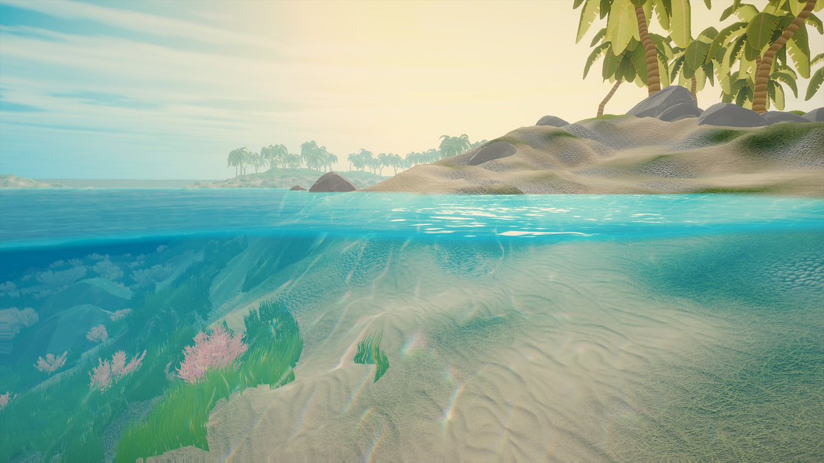
also trying to achieve an underwater look when swimming beneath surface
i think I want pretty much just like Fog effect just a lot stronger than above surface. is it possible to make unity fog be different above/below water simultaneously ? i.e. if player camera is half underwater half over water, each looks correct for above & beneath water
i like the "seamlessness" of it, that thin line where surface meets player camera underwater, above surface rendering with above-surface effects, below surface has underwater "fog" and other effects
check out this twitter thread: https://twitter.com/_staggart_/status/1411339746828226561
Some background on how I'm rendering the water line, because it's almost arcane 🪄 #unity3d
The key goal is figuring out if a certain pixel on the screen is above, or below water. This in turn can be used to apply effects to a specific part of the screen.
Likes
821
Retweets
143
👌 thanks
for noob like me i wish there was some code / examples so i could try implementing these concepts in my own water...
I did but seems unsupported + it doesn't seem to render the material at all with the rp
Does it give any errors?
No it just isn't visible at all
I believe this render pipeline only renders things with its own shader applied so just needed help seeing if I could make my shader work with it as well
with using translation, rotation, and scale matrixes, can i combine them all into one matrix for multiplication?
just im trying to get matrix positioning, scaling and rotation in but its not really working right
@cursive swift you should watch the order
for example if you translate first and then rotate,
it will be like orbiting around a point
should I split the matrix up into three matrices?
translate * rotate * scale
this is probably what you want
translate * scale * rotate
would also work (if your scale is uniform)
nope, you can combine them like this
like how?
just multiply them?
translateMatrix * rotateMatrix * scaleMatrix
unity also has something called Matrix4x4.TRS
thats should give you something similar
gives you a transform martix from position rotation and scale
okay, im using the unity TRSMatrix, but im still encountering an issue with the transformations being incorrect.
Cause atm, rotation is scaling the texture, scaling up is scaling down the texture, and position does nothing
and in the shader im using mul() for multiplication of the current position with the transformation matrix position
oh wait
rotation is working!
okay, its not rotation around its center
`[numthreads(8,8,1)]
void CSMain (uint3 id : SV_DispatchThreadID)
{
float3 baseNormal = NormalFromHeightMap(id);
for (int i = 0; i < Count; i++){
float3 newID = mul(float3(id.xy, 1), TRSMatricies[i]);
float3 normalColor = layerMaps[float3(newID.xy, i)].xyz;
    //if(!all(normalColor))
        //normalColor = float3(0.5, 0.5, 1);

    baseNormal = BlendNormals(baseNormal, normalColor);
}
float3 finalNormal = BlendNormals(baseNormal, overlayMap[id.xy].xyz);
Result[id.xy] = float4(finalNormal, 1);
}`
is this looking good?
granted this is just a snippet
but im more concerned about if im getting the right ID from that multiplication
im definitely not getting the right id
its rotating, but also being quite buggy
ill get an image of the results soon
but in short the rotation, while working in rotating the texture, is also stretching the texture out
and the positioning does not work at all
Could be, although the system is supposed to be designed to work in large outdoor areas like that. That's why they put it all in there. But if planar reflections work for ya, cool 🙂
The challenge you're having is really performance, because you want to support lower end mobile and you want reflections, so you're going to have to find a way to "cheat like hell". Remember, it doesn't have to be accurate, it only has to look good enough to fool people most of the time.
I'm having a problem in a new project

It happens when I import the shader package to anotehr project
Does anyone know any solutions
Or how to do this

Liek copy the graph folder from another project to the current project?
Using URP, is it possible to add a user defined pass to ShaderGraph graph and render that user defined pass with ScriptableRenderPass?
No
Yes, that's the idea, copy the metadata to keep the references.
You could also use the assets packages export/import
TBH the game i keep using as reference only had water reflection for Very High and Ultra High graphics settings, so i think i might also need to concede that only high end mobile devices will be able to have those reflections
having said that - i would love to figure out how to do reflection probes & blending & all that and that it actually works correctly and doesnt look horrible as i've been seeing thus far... how can i investigate further how to do them better? can I maybe send you a sample project & scene so you can also see more specifically either how horrible it ends up looking or how wrong i'm doing it?
I also volunteer to help 😉
Im running 2022.1.16f1 HDRP. Is the tessellation feature not working when creating a new shader, or am I missing a setting aside from checking the Tessellation box under Surface Options?
Did you set the tessellation factor to something >1 ?
I played around with all the sliders and nothing seem to do anything.
And you did save the shadergraph, for it to compile and apply modifications ?
From what I know, it should work
The shader compiles and I'm able to assign other textures and change sliders based on my setup. Everything else works except for the tessellation feature
Do you mind to show some screenshots ?
Graph settings + Material inspector
I'm creating a new one in .17 and see if that version fixed it. I'll post if its still not working
in shader code instead of in a texture (like below), is there a way to pinch both sides of a regular square UV layout into this hexagon shape?


visual to make it more clear what im asking - this but in code
I know I will have to mask off the four quadrants and then apply a transformation to them
but the specific transform is not a scale or a offset, its like a shear?
and im not sure how that's done
- To scale by the vertical center, the logic is : y = (y-0.5) * scale + 0.5
- To make it as a trapezoid, you need to modify the scale value depending on x
- To make it symetric, base your scale as if x = 0.5, scale is 1
It's mostly all about remapping values
@amber saffron

@amber saffron It still doesnt work. I'm using Unity 2022.1.17f1 with HDRP
This is set to 1 : doesn't add more divisions to the mesh

Something like this? (one minus only because its easier to see the shape)

Tip : you can change the preview to display in 2D, might help 🙂
you can!?
Oh, haha That fixed it, thanks!
Select the node, in the "node settings", set preview to "Preview2D"


hrm a problem, how do I return it to a range of 0-1 instead of -1 to 1 so that I can use it on a texture?
its easy to do the distortion from the center, but then how do I return it to centered bottom left?

I tried remap but that just shifts the whole thing over
I need this, but what I have is


Add 1 then divide by 2
but yeah remap should work
to what? remap didnt work

once ive distorted it based on the center point, I need the distortions to remain exactly in those positions while moving the range back to 0 - 1, remap isnt doing that
remap is just offsetting it
this is the expected


but this is the result I have
not at all what I wanted
Sorry I need to get my brain into the right mode for thinking about this stuff
Wait a bit, I'm doing the graph
Your brain is already there 😄
kk
yeah im no where near close to knowing what to do, I cant solve it, ill just wait

I wish I COULD solve it, its so frustrating to not be able to do anything without help

not this either

I would have never gotten this, setting up yours now
hrmgh
it works
but it doesnt meet my use case
I need to apply another transformation on top of that one
but if I try to do it first, it breaks the hex
and if I do it after, it breaks the hex

this is what I get if I try to transform it before shaping it into the hex
but I cant figure out how to transform it after I shape it into the hex
what are you trying to do
as usual this entire thing was an xy and it didnt solve my y
trying to fix these stupid distortions again


what I have

what the hex gives me
the hex might work but I cant plug my transformed UVs into it
I can use the upper or lower, there's no real difference
hex doesnt work on either though

here it looks like you're still using the original UVs somewhere i think

you are right of course
how do I replace that?
I tried plugging mine in but it doesnt work because that one is not in the same space as the first one
i think after the rotate around axis, you can plug that into where the UVs would go

that doesnt work, thats what I meant by saying I tried plugging mine in

I just remembered that mine starts centered
so I skipped the subtract 0.5 part sincei t was unneccessary
its better
but it doesnt fully fix it
you tried to tell me how to fix it in the past
the problem was that that solution, by deforming the hexagon, just ended up splitting it into three squares; across each face the noise was nice, but since the faces weren't in contact in the new UVs, the noise had discontinuities at the edges
you implemented it fine, the problem is inherent to the solution
Yeah

extreme example
but I think maybe the problem right now is that the falloff between shear and not shear is exponential or something
you can see how half of it is barely distorted at all

I think I need to change the range/power/exponent/log of whatever is being done to affect more of it maybe
I think the problem is that of mapping a convex object onto a flat surface while minimally distorting it, which is not easy to do
yeah obviously that's the most problem part - that this isnt easy
its better than it was before at least I guess
ill just drop it and move on
you can't do it without introducing discontinuities or some distortion
there might be a way of doing it where the distortion is very hard to see but idk
Hey anyone knows if this VScode extension works with unity? https://marketplace.visualstudio.com/items?itemName=A2K.hlsl-preview
whenever i try and open the preview i get an error telling me it cant find the UnityCG.cginc file from the #include
Extension for Visual Studio Code - Real time preview for HLSL shaders
It doesnt seem like it would work at all
yeah, i had that suspicion. welp it would be nice tho if it did
Would be nice if we had auto complete, navigate to definition etc etc for unity shaders in vs but no
yep.. is there any IDE that has it? i havent heard of anything that does
Rider has it built in but I had problems with it too so I dropped it
ah, isee. im mainly not using rider since its less customizable with extensions
anyway while talking about extensions for vs code. which ones should i use for writing shaders? (just in case i've missed something)
i guess rider is better but im not a big fan of it 
but maybe i should give it a second shot, cuz the c# extension for vscode constantly breaks for no good reason
the new 2022 one or the 2019 one?
ah, ok i'll give it a try for a couple of weeks then
Anyone have any experience writing a texture-based input light ramp in hlsl?
And @amber saffron...
Sure, I would suggest something like a github or dropbox, and perhaps start a thread here.
I won't likely be able to get to it until this weekend though. Real Life keeps getting in the way of my virtual internet-based one. :/
The. Matrix. IS. Real. Life.
if I have an image like this, can I do anything in shadergraph to create a smooth gradient between green and pink?

you could make a custom node to do a Gaussian blur
is shader graph a good way to get the basics of shaders? or good way to learn later shader coding?
read nearby pixels, average their colors, and set your own pixel based on that average?
it's a good way to learn how to think about how shaders work and make shaders yes
I have custom voronoi node and I just noticed it outputs in gamma space and not linear space 🤔
Looking through the code though I don't see any Pow(2.2) happening anywhere

    float2 res = float2(8.0, 8.0);
    for( int j=-1; j<=1; j++ )
    for( int i=-1; i<=1; i++ )
    {
        int2 b = int2(i, j);
        float2  r = float2(b) + voronoi_noise_randomVector(p+b, AngleOffset)-f;

        float d = dot(r,r);

        if( d < res.y )
        {
            cellUV = r;
            res.y = d;
            mr = r;
            mb = b;
        }
    }
Distance = res.y;```no pow here either but its more complicated so maybe some part of this is doing it?
inline float2 voronoi_noise_randomVector (float2 UV, float offset){
    float2x2 m = float2x2(15.27, 47.63, 99.41, 89.98);
    UV = frac(sin(mul(UV, m)) * 46839.32);
    return float2(sin(UV.y*+offset)*0.5+0.5, cos(UV.x*offset)*0.5+0.5);
}```You mean like that used in toon shaders? (it's a light ramp that could be texture based)
If so, google is your friend, initially
Well, if you're convinced that it is non-linear, and you're operating on gamma corrected textures/results/output, you could if you want convert it to linear first by ADDING a pow function...doing your calcs....and then ADDING another pow function to convert back to gamma.
That's assuming you're in gamma mode (I'm not running unity right now but check Edit -> Project Settings -> Player -> Other Settings. That's where it USED TO be at least.)
https://www.kinematicsoup.com/news/2016/6/15/gamma-and-linear-space-what-they-are-how-they-differ

KinematicSoup Technologies Inc.
Linear space lighting is a term that game developers are becoming ever more used to hearing as games reach for the next level of realism with physically based rendering models (PBR). Though linear space and its counterpart, gamma space, are fairly simple and important concepts to understand, many de
It's worth researching if there's macros for such, and if so use them.
this confuses me, are you saying this image is not in Linear color space?

to the best of my knowledge, this is linear color space

and this is what gamma color space looks like, pow 2.2

am I wrong?
I'm not understanding what you are trying to say
d = dot(r,r)
that's why it's squared
that's the square length of the vector
if you just return the square root of that instead (or swap dot(r,r) for length(r)) then it should work and be linear
(dot() is slightly faster so maybe do the square root at the end, though it probably won't make much difference)
I'm replying to this ^^.
YOU said it was gamma.
if you want it to be linear, add a pow function to the results.
But what's also important is how your unity render pipleline is set up. So if you need to convert back to gamma, apply the reciprocal power function back. See the article I linked.
Basically, I'm saying you can do it in shaders. You should be able to operate in whatever color space you want.
Those look like correct interpretation of "what is linear" and "what is gamma" to me.
What that article explains is that you can have inputs (textures or function) that are in gamma. Sometimes shaders just operate on that, with or without applying a pow() function.
But in things like PBR, you'd want linear, so you'd have to convert it manually if the function code you have is outputting gamma.
is there a way to set a pixel in 2 textures in 1 shader frag? Both textures are the same resolution and would have the same coordinate passed into the shader fragment
Oh okay, yeah I was just confused. I did know what linear and gamma were, I thought you were telling me I had it wrong
I want to try using a second texture to keep track of where a drawing brush has drawn to make opacity work better
Research MRT (multiple render targets).
I can't get the existing color in any of the textures I'm outputting to
tried half4 col : COLOR for the main one in the frag input struct and half4 col = tex2D(_DrawTex, i.uv)
if I draw to a temporary rendertarget, half4 col = tex2D(_DrawTex, i.uv), then copy the temporary rt to the DrawTexture it works
but that would mean I'd have to create 3 extra rts
this is what I was doing with the structs```
struct v2f
{
float2 uv : TEXCOORD0;
float4 vertex : SV_POSITION;
half4 col : COLOR;
};
v2f vert (appdata_full v)
{
v2f o;
o.vertex = UnityObjectToClipPos(v.vertex);
o.uv = v.texcoord;
o.col = v.color;
return o;
};
FragmentOutput frag (v2f i) : SV_Target
{
half4 col = i.col;```
also tex2D() isn't working on any of the 3 textures I'm outputting to
but it seems to work on ones I'm not drawing to
I need to get the existing color for all 3 textures
Are you actually using that col anywhere?
yes
Okay. Are you sure your mesh has vertex colors?
also I found a post on stackoverflow saying you cant read in the shader but the appdata_full does have a COLOR input so why can't I at least read the main one
also
^
just cant read from the same texture you're writing to
stackoverflow said it's intended behavior (or at least consistent)
Here you're getting the color of the vertex and transferring it to the fragment shader.
That you can't for sure. It should cause an error actually.
it's a difference of changing the first line in frag to half4 col = tex2D(_DrawTex, i.uv);
What is?
this
hmmmm wait
I wonder if appdata_full COLOR is the vertex color not the texture color
I bet it is
Okay. Then share the relevant code.😅
What kind of answer do you expect if you share the wrong code?
It's whatever you set it to. If you set it to vertex color in vertex shader, it will be vertex color.
struct v2f
{
  float2 uv : TEXCOORD0;
  float4 vertex : SV_POSITION;
};

v2f vert (appdata_base v)
{
  v2f o;
  o.vertex = UnityObjectToClipPos(v.vertex);
  o.uv = v.texcoord;
  return o;
};

FragmentOutput frag (v2f i) : SV_Target
{
half4 col = tex2D(_DrawTex, i.uv);```for the input appdata
not something I set
Yes, the input data is always coming from the mesh. If it can map the attributes correctly.
If you want to read and write to multiple textures, I'd use a compute shader instead. Makes it way simpler.
also I didn't share the wrong code that was when I thought appdata_full.color was the texture color and was wanting to know why it wasn't working
Okay, then I misunderstood, because you were talking about one thing but your code was doing something else...
Anyways, does that solve your issue?
I'll look at compute shaders tomorrow
or maybe way later I kinda want to get this thing working in the first place and then clean it up
@meager pelican @amber saffron re. Reflection Probes for cheap water reflections
Hope you don't mind me pinging you
https://github.com/kingIZZZY/water-reflections-1

for reference - this is the effect i'm hoping/aiming towards achieving, or anything as close as possible as cheap as possible. But if not possible with cheaper tactics on lower end mobile devices - then i guess i might end up needing to do Planar Reflection supported only on higher-end mobile devices
How to use the object scale node of an object marked as static? Is the only alternative to unmark the option?
The problem is that static objects are batched, so their scales are set to (1,1,1)
right now I'm just unmarking "batching static" as off, but I wonder if there is a more elegant solution
The whole point of batching is that several meshes are drawn as one(in one draw call), so they can't have individual parameters. You'll have think of something else or avoid batching that specific object.
It's fine. It works well when disabling batching, and the whole point of scaling in this case is to avoid having multiple meshes
I'd argue that several different meshes with batching are better than several objects with the same mesh unbatched...
Unless memory is a concern which is unlikely.
we are talking about big objects that will most likely be culled. Possibly one or two in the screen at once. It won't make much of a difference
Hi! Probably something very dumb. I have a SpriteRenderer with a sprite, and I add a material to it:
            var hurtFlashEffectShader = Resources.Load<Shader>("Shaders/HurtFlashEffect");
            Assert.IsNotNull(hurtFlashEffectShader);

            this.hurtFlashEffectMaterial = new Material(hurtFlashEffectShader);

            var mats = this.FlashingSpriteRenderer.materials;
            var newMats = new Material[mats.Length + 1];

            for (int i = 0; i < mats.Length; i++)
                newMats[i + 1] = mats[i];
            newMats[0] = this.hurtFlashEffectMaterial;

            this.FlashingSpriteRenderer.materials = newMats;
There is no API for it so I just reconstruct a new array of Materials.
Then I just have a shader that always outputs the color white, and this is the result (screenshots: before, after)
The white space around seems to be a clamping issue, but what bothers me most is that the original sprite conserves its color, without being overwritten by the white color returned by my fragment shader.
I'm using the blend mode Blend SrcAlpha OneMinusSrcAlpha.
Thanks in advance.

Nepho help
Is it normal for MeshInstancedIndirect not being captured by the profiler?.. This at least millions of grass on a Terrain... but the instance said to be 0 in the profiler..?
Any idea?
and the batces shown there are the instanced terrain, so they're not the grass
Profiler info is based on the cpu side graphics api calls and MeshInstancedIndirect is just one draw call afaik. So no wonder that it doesn't show. Also, unlike materials with instancing, it's a lower level graphics api, so I'd assume it's bypassing some of the profiler/diagnostic routine.
that makes sense! good god 😆 ... Finally I can rest assure... I thought it was a bug 👍
Many thanks dude! 👍
btw the instancedIndirect was done completely in Shadergraph! thanks to @regal stag blog post that is!
Hello, I'm probably missing something obvious but while trying to sample some noise from a texture I've noticed that const float noise = clamp(noiseTexture.SampleLevel(SampleClampPoint, texCoord,0).r,0.001,1.0); gives me lower values than expected.
I've tried writing all samples to a render texture to compare it to the original texture on the CPU. It seems the samples return something a little bit above of the square of the expected value. Is there a common mistake that could produce this result ?
Some sRGB / Linear colorspace issue ? 🙂
That was it !!!! It's been driving me mad
Classic 😉
hey @amber saffron 👋 😃 lemme know if you have a chance to peek at my use case example project 👆
as for planar reflections themselves - https://forum.unity.com/threads/urp-planar-reflections-guide-example-tutorial.1342613
any help on how to put together this PlanarReflections.cs script to get it to work would be greatly appreciated 🙏
I did not realize at all that you were using URP, would have been way more easy in HDRP 😅
ahh i see... ye i'm trying hard to target mobile support, and however much possible - even medium-low end devices, ex. i'm testing with an LG G4 with Android 6.0 which i think supports GLES 3.1 but no vulkan (i think)
I saw that Andre answered you forum post, hope it helps you setup boat attach reflection 😅
Else, I have a dumb suggestion : import your assets in the boat attack project with their water :p
trying that right now...
pros: maybe i'll get planar reflections to work. cons: 1) the boat attack water is a bit too realistic and not exactly the style i was aiming for in my particular project... 2) i feel like the boat attack water might be a bit intense performance-wise compared to a much simpler shader i had from a tutorial i was following - much fewer features & shadergraph nodes & options & settings etc... (ironically - that tutorial i was following was the water shader video from a few years back from the boat attack demo itself 😛 https://www.youtube.com/watch?v=gRq-IdShxpU)
Not sure if this is the appropriate channel for this question, but does anyone know how I can edit a material so it doesn't have a shadow part? Ideally, I want the light to be evenly distributed, or for the material to cast its own light. Either way, I don't want it to look like this lol

turn off shadows on the model/mesh maybe? (not the material)
Ok thanks, I'll try that.
Soo ... basically, you want an unlit material ?
hi!! bit of a shader graph newbie here who needs a little help - essentially im struggling to get a gradient to smoothly transition from a to b colours when one of them is dark - it seems to get overwritten by the lighter colour? ive tried playing around with different ways to blend (blend node, gradient, lerp) but none of them are giving me the effect im looking for. the pics are of my shader graph setup, the result, and what im aiming for
https://cdn.discordapp.com/attachments/1015782621453750373/1024862767926227014/unknown.png
https://cdn.discordapp.com/attachments/1015782621453750373/1024862768320487565/unknown.png
https://cdn.discordapp.com/attachments/1015782621453750373/1024862768723132506/unknown.png


Yep. Well I'd like it to glow on its own. That way there's no light or dark part, because it's supposed to be an energy shield.
Really sounds like unlit to me
You are remapping the position.y value from -1;1 to 0;1 : what size is the mesh you are applying this shader ?
Yeah, that's probably what I'm looking for. I'm not exactly an expert on this type of stuff. 😆
@amber saffron aside from the planar reflections - can I guilt you into helping a bit with finding out if i can achieve some acceptable level of water reflection effect using reflection probes? 😛
its 4/4/4 rn but scaling it up / down doesnt seem to change anything

thats it at like 200 lol
The shader you've showed is expecting to work on a cube of size 2units, when scaled at 1,1,1
Will be hard by using only cubemap reflection probes, as they are static
right... i thought so... at least it's helpful in the sense to know conclusively (is it conclusive?) that reflection probe cubemaps -especially baked ones - won't really be a good solution for my use case
Change the shader to unlit
@meager pelican was suggesting that there was some way to get reflection probes to work good-enough in place of planar reflection... but so far they seemed too static according to my tests to work in a large outdoor scene like my project
For low end mobiles, you can use old school hacks to fake planar reflection, like double rendering with invert scale
isn't that exactly what planar reflection is? rendering a 2nd time and applying to water render texture?
The default unity sphere is -0.5 to 0.5, so that's what you want in your remap (instead of -1 to 1). (iirc same goes for cube and quad).
Ok thanks. I'll try and figure out how to do that.
I'm talking of rendering your islands twice, one upside down, with a transparent water in between, to fake reflection 🙂
That's how the mirror in mario 64 was done 😄 https://www.youtube.com/watch?v=sG3Hlmi1-3A

Using cheats i got behind the mirror in the mirror room!
5 likes for a video with the cheats in the description!
right - i thought that's exactly what planar reflection is by definition
i think eg reflection probes make a cubemap of the surroundings from the water's perspectives, and then sample that for reflections. Curvy surfaces look better that way
(but you can use a screen space distortion on your double render too)
Not exactly
thanks! so i tried that and it definitely helped, though the darker colour stills seems to be getting overpowered - maybe its got something to do with how im blending them? rn im just using the blend node on overwrite


To blend two colors, lerp should be enough
would love to find out how to do this & try it...
and this
I'm not too well versed in perceptual stuff but the way your eye sees color isn't linear, so to have it blend smoothly (especially between dark and light) you would want to account for that. Maybe try just squaring the time input in the lerp?
no idea why but that works! thanks a lot lol (remy too) i think ill still have to fiddle around with it a little but that seems to have solved the blending issue
Iirc the perceptual brightness is roughly the square root of the linear brightness; glad it worked :)
i like ur funny words magic person
cubing it makes for some cool results too
you could also try using a smoothstep instead of a lerp
that kinda makes the colours go funky but it looks cool lol

Uh oh. 

https://youtu.be/LKnqECcg6Gw This video explains a bit what's actually happening
Have you ever used Shader Graph? There's a good video by Brackeys on making a shield effect
No, but I'll check it out, thanks!
tyty I'll take a look at it
I feel smart I figured out how to properly make a drawing brush shader (I've heavily edited a lot of stuff with the DrawTextureUI addon)
When you're drawing in a straight line, does it just detect new pixels at the front so as to not keep adding alpha until it's opaque?
it uses an RHalf texture to keep track of alpha so it doesn't keep reapplying alpha and also lets it use the max alpha like if the brush isn't uniform and it uses a second texture thats the original texture before drawing at that spot for the color to blend with the brush so it doesn't keep reapplying the brush
thats what the 2 things in the top right are
basically it only samples the original texture before drawing and only applies the maximum alpha
I'm going to eventually make the extra textures only size to as big as they need to be to fit the stroke
and also look into compute shaders so I don't need 6 textures (3 temp ones so I can effectively sample and draw to the same textures)
Hey so I know _MainTex is the reference id for the texture provided by SpriteRenderers.
What's the reference id for the color?
_Color?
Hello, any idea why Material.HasProperty(int nameID) is returning true on the Standard shader for a property it doesn't have?
Im checking as follows:
if (mat.HasProperty(SeparateCutoutTex)) {
    Debug.Log(mat.name + "of type " + mat.shader.name + " has it");
}```
Any help is appreciatedcc: @amber saffron
So the idea was to try using unity's built-in reflections, and "cheating" by having several static baked probes.
-OR-
Trying out baking the nearest probe, really low res and maybe 1 layer only, one side per frame rather than having it static.
IDK if you can pull any of that off on lower end mobile, and you can always update them at very select times only via script.
But it seems that @leaden turret was having a problem getting them to work at all....I think even in the editor.
I have no problem with planar reflections either, conceptually.
Hey uuuh anyone know what's up here?
Scene View:

Game View:

_>
Shader

If I put any shader on these textures something breaks.
They're rendered as UI elements
Can't figure out why HasTexture will return true even when the material doesnt have that property, this is what the console outputs:

Code is:
 int SeparateCutoutTex = Shader.PropertyToID("_SeparateCutoutTex");
 if (mat.HasTexture(SeparateCutoutTex)) {
   Debug.Log(mat.name + "of type " + mat.shader.name + " has it");
   mat.GetTexture(SeparateCutoutTex);
 }
This looks like a bug
Indeed looks like that
To reproduce: 1. Open project 2. Play scene Expected vs Actual: 'HasProperty after SetTexture' message should have false value inste...
which was closed as designed
I think that might be the case here, I think another script tried already to set that property and failed
hence the property gets registered in the material
However I dont think that should be as designed
That is confirmed

again, dont think this should be as designed
Hey sorry to bother, I have a question about a certain effect that I want to accomplish for a project I am working in, I want to clarify I am a gameplay programmer not an artist or technical artist by any means I am quiet dumb regarding all of that so sorry for my lack of knowledge in this just to see if anyone can lead me in the right direction
So this is a rythm game with multiple kinds of notes, the hold note the idea behind its graphic it's that it is surrounded by that shape almost like a chain of sorts with a big and a small spool, the part I have trouble with is that this shape needs to adjust according to the note, sometimes the hold note will be longer so the chain would need to get bigger, sometimes it will be smaller and also the circles change in size the closer they get to the click prompt, so a simple sprite scaling wouldn't work as if you stretch it it would stretch in all directions, ideally I would like something that can adapt to the size of the circles and the distance between them, any idea how I could achieve this? I am pretty sure I need to use a shader but again I am so bad with shader and the sort

Any help is appreciated, being banging my head a couple of days searching for a way to simulate this but I am so bad with graphics
Shadergraph doesn't have proper support for UI yet, iirc it tries to render all the passes the shader generates, which might be why it looks like that (Frame Debugger window can probably confirm)
I think it works better if the UI is set to Screenspace - Camera rather than Overlay mode.
Reproduction steps: 1. Open the attached project "1376328.zip" 2. Open Assets > Scenes > SampleScene 3. Observe Game view and ...
That's pretty insane ngl.
I think it's through Vertex Color
im struggling with this big time, is there a way for unity to lay shaders on objects overally, not on their uvs?

they just look weird
look into triplanar shaders perhaps?
not 100% sure what you're highlighting and what your desired look is here though
look at the dots on the 3 parts of the mesh
they are all messed up, the density should be persistent
i guess the only "problem" would be whether planar reflections is less performant than any of the probes solutions you described
i might not have tried these techniques yet... i basically just tried setting up probes around the scene and baking them and seeing how they look with blending. does it make sense that that in itself just wont do because reflection probes like that are too "static" for the effect i'm hoping to achieve? are the techniques you're describing a bit more "dynamically adjusting based on any viewing angle player might be moving around from" ?
Seems you are looking for a screen space effect instead
working with noise question, what would be a good method to 'smudge' a noise so that the peaks / valley in gradients are less linear? A lot of the noise nodes are some form of light->dark gradient, I want to distort those gradients

ive tried various blends or math algebra but I havent been able to move the peaks /valleys around in a more smudgey way, it keeps ending up soft gradients like this

Without blurring I suppose simply decreasing contrast might be the best bet
i think it would probably be easiest to just have a linerenderer with points marking the chain, and then run through the points as necessary to change the shape (maybe that could be sped up with a compute shader but there is some overhead associated with that so it might not be worth it.
Alternatively you can look into combining some distance functions (Inigo Quilez has a page full of them) and then drawing if the distance is between two values.
well that would be the case tho the problem lies when an object that also has that shader is far away
i do have an option for that and i tested it, but it doesnt looks that good because of distances
the camera can be up close or more distant to the player and the density shown on the model will differ
ill try it again tho, been a minute
you could try distorting it with some more noise (uv -> uv + (noise1, noise2) -> final noise) and then based on how far you distort it, you do what Spazi suggested and change the contrast as well
so it's like the more you smudge it, the lower the contrast
I'm a little unsure how to use contrast in this situation - lower contrast brings all the values closer to grey, but that won't move the position of the peaks and valleys to my understanding, wouldnt that just make the difference in values shallower?
if you distort it and lower the contrast where it's distorted i feel like it'd look like it was smudged
dxc doesn’t as of yet seem to support hlsl 2021 
I have 2 assetbundles, one with my character and one with my shaders
im loading both and instantiating the character, but the shader appears fully black for some reason
help
can you clarify what you mean by contrast? I am trying to follow your instructions but my result is just foggier, its not smudged at all


im trying to produce this appearance
but its not just 'noise' its a VERY specific shape
not just any shit added together makes this exact look
it looks that way because the dye is folding over itself as it gets poured into the mold that made it
distorting the UVs isnt producing smudge because it distorts the UVs, the resulting noise itself is still unchanged gentle slopes and valleys linearly spreading out
no matter how messy the edges get

lol the automod bot deleted my message
I guess smudge is too racy?
oh its the picture
the bot wont let me post this picture
Changing the Rendering Path from Forward to Deferred somewhat fixes this but it results in no lights working on the map. Only emissive.
those colors look like UVW channels
no idea why they'd be rendering over top of your world though
Me neither. I figured it might be some sort of shading issue but I thought it might of been per-object. Not globally.
I ticked off the 'Strip Unused' from the Renderer to see if that does anything. Building it is taking some time.
https://cdn.discordapp.com/attachments/996979168304697384/1025243994378207242/unknown.png
I am not getting anywhere without help, without instruction
Every attempt I make builds up more and more complex, using more and more layers of noise
it becomes completely rigid, I cant change anything, I cant do anything

its just a huge piece of shit that looks nothing like what I want, and no matter what variables I tweak, no matter how many more layers I add on top, it never fucking works
and its so completely rigidly paralyzed that I just have to delete everything and start over because its so completely fucked I can no longer see the forest for the trees
Seems more like some debug/visualization type of mode is enabled
This is on a built version though.
You'd think this would show up in the Scene Editor/Game.
Nothing really special enabled in here.

I know. There are most likely similiar options available for build too
I reset the Player Settings completely and that didn't do anything at all. 😦
And again with forward rendering this happens. With deferred rendering, point lights seem to be completely broke across the scene.
anyone know a fix?
If you use Addressables, the webgl build includes all possible shaders variants into your memory. Normaly you can select shaders you want with shaders collection and strip everything else on build. But it seems terrain does not work the same way, so I thought maybe anyone knows some tips about that.
Hey question. If I made a material and want this material to have a slightly different setting on 1 specific gameobject/prefab (like color for example), do I need to make a whole new material just with this setting?
Reflection probes can blend. But dynamic objects....move...and won't be in the baked images, of course.
So you know what I would do if I were you? I'd go make an empty scene or even new project, and put some reflection probes around, and some "fluff" scenery, and create a material and put it on a ground plane....black albedo and 1.0 metallic reflective. No special water shader, just reflection, with the standard shader.
Bake the probes, and see how they work/blend. See how it performs on mobile with 100% baked probes. Maybe try it with just a simple-specular shader too, see if the stock shader supports probe blending. And test on lower end mobile.
Once I had an idea of how it all works and what performance is like on the targets you're after....THEN...I'd go see if a custom shader is much much faster than stock stuff.
That's not to say you won't still need your water shader. But you're basically asking questions about "how Unity works" and rather than me telling you (and maybe being wrong or under estimated the performance costs) you should try it out "stock" and see if you even like the effects. Read the docs on reflection probes too.
I have to get to work, so I apologize for being brief, I just have limited time right now.
and @leaden turret
Unless you are in HDRP, reflection probes don't blend per pixel, but per objects.
MaterialPropertyBlocks can be used to override material properties per instance (SRP batching won't support it but also it shrugs off extra materials)
You can also have a shader that can change its appearance with different UV coordinates and vertex colors which can be different per mesh
Is this something that can be done from the inspector?
I understand that you can create new instances of materials and modify them from scripts no problem.
No, MaterialPropertyBlocks are modified through scripts, similarly how you would create or modify material instances
Oof. So no way to define specific material settings for certain gameobjects in the inspector?
I literally have to make a new material just to change some simple thing like color?
No
With material instances yes, with material property blocks no

Set the material to transparent, with refraction enabled, and assign a IoR value
The names are very confusing :/
"IOR" is for the eye shading model, "Index Of Refraction" is for transparent with refraction
ahha i see i think IOR is Index of Refraction at first.
How I can make dotted outline with shader graph? Like there but only in contour : https://lindenreidblog.com/2017/12/24/animated-dotted-outline-shader-in-unity/

A tutorial on how to write an animated dotted outline shader in Unity/CG.
I using Quick Outline asset and want to rewrite it a bit for dotted style
But seems like it's not appropriate for this : ```cs
Shader "Custom/Outline Fill" {
Properties {
[Enum(UnityEngine.Rendering.CompareFunction)] _ZTest("ZTest", Float) = 0
_OutlineColor("Outline Color", Color) = (1, 1, 1, 1)
_OutlineWidth("Outline Width", Range(0, 10)) = 2
}
SubShader {
Tags {
"Queue" = "Transparent+110"
"RenderType" = "Transparent"
"DisableBatching" = "True"
}
Pass {
  Name "Fill"
  Cull Off
  ZTest [_ZTest]
  ZWrite Off
  Blend SrcAlpha OneMinusSrcAlpha
  ColorMask RGB

  Stencil {
    Ref 1
    Comp NotEqual
  }

  CGPROGRAM
  #include "UnityCG.cginc"

  #pragma vertex vert
  #pragma fragment frag

  struct appdata {
    float4 vertex : POSITION;
    float3 normal : NORMAL;
    float3 smoothNormal : TEXCOORD3;
    UNITY_VERTEX_INPUT_INSTANCE_ID
  };

  struct v2f {
    float4 position : SV_POSITION;
    fixed4 color : COLOR;
    UNITY_VERTEX_OUTPUT_STEREO
  };

  uniform fixed4 _OutlineColor;
  uniform float _OutlineWidth;

  v2f vert(appdata input) {
    v2f output;

    UNITY_SETUP_INSTANCE_ID(input);
    UNITY_INITIALIZE_VERTEX_OUTPUT_STEREO(output);

    float3 normal = any(input.smoothNormal) ? input.smoothNormal : input.normal;
    float3 viewPosition = UnityObjectToViewPos(input.vertex);
    float3 viewNormal = normalize(mul((float3x3)UNITY_MATRIX_IT_MV, normal));

    output.position = UnityViewToClipPos(viewPosition + viewNormal * -viewPosition.z * _OutlineWidth / 1000.0);
    output.color = _OutlineColor;

    return output;
  }

  fixed4 frag(v2f input) : SV_Target {
    return input.color;
  }
  ENDCG
}
}
}```
The image you showed is basically an outline with screen space scrolling lines.
So, taking the shader you showed, add some scrolling diagonal lines in the fragment stage and it should be good to go
is it possible to make one pixel draw in another pixel using hlsl or are all the pixels entirely self contained
Hey I need some help. Does someone know why I get this weird black lines at the sides? I guess its coming from the Alpha but my Alpha should be working correctly. I use Shader graphs


You can't for a few reasons.
- It could cause a race condition
- The pixel of a fragment shader thread is decided from the mesh triangles projected to the screen. If you want to change that, you'll need to hack the GPU rendering workflow(which is probably only possible with physically altering it)
yeah i was 99% sure it wasn't possible but i had painted myself into a corner so had to check 😂
thanks tho
What are you trying to do though?
it's too complicated to tell my shader is like 1600 lines long. basically i wanted to draw a line on a tile above but the earlier stages of the code make me only able to draw within the current tile. but i can work around it.
Are you mixing in a texture somewhere?
can you post a larger image of your graph?
Sure here is a picture of my full graph

For some reason, it's smaller so the text is unreadable
I dont think so. Only multiply
This should be better I hope

yes it is, thanks :)
Try putting it through a saturate or abs node before it goes into each of the power nodes
Powers don't like negative numbers and may act up there
Or just after splitting the uv sampling should be enough perhaps🤔
Works! Great thanks a lot guys 🙂