
#archived-shaders
1 messages · Page 14 of 1
btw, i fixed the black side thing
now textures under the top one are visible too
oof
Are there any blocks that will be transparent though, and would you not want them to use a separate mesh (so they can be displayed on top of, rather than seeing through, the opaque blocks)
yes, there are transpearent blocks, and making a second mesh is bad
I think the problem is that since transparent faces need to be rendered as transparent (so stuff can be behind them), they can't be sorted like opaque faces and so it instead sorts them by some approximate metric which doesn't always work, and so you get stuff like that
Where faces that should be behind render in front
is there a way to fix it without making a second mesh?
I think the way Minecraft does it is to create multiple meshes, for transparent stuff like grass and leaves and for opaque stuff, and then renders them both individually.
Idk, but if there is it's probably deep inside the transparent rendering system
From geometry there probably is a way to do it but idk how cheaply it could be done especially since you will always be rendering all the faces along a line of sight, whereas an opaque shader would only render the front face
anyone? 😅
fixed btw
i just changed 1 setting on Shader Graph
what did you do?
how is it related to my question? 😅
change zTest to

Does that still work for the things you want to be transparent?
i tought you wanted to see only the image from one side, srry
nice
i think you need URP for that btw
Hi everyone, I want to improve the skills of a dev on shaders, he starts from 0, can you suggest digital resources available? I bought "the shader's bible", I find it too theoretical. Thank you!
There are resources pinned to this channel that are worth looking over
Rendering everything as transparent is likely worse for performance than splitting meshes
You can use cutout / alpha clip with opaque rendering mode to not have the issues of transparency
Cutout in shadergraph?
This can make you unable to see other objects through semi-transparent objects. If you dont have semi-transparent meshes, just use cutout shader
Thanks a lot, didn't notice
Cutout and alpha clip are used interchangeably, I don't recall which
hey there, first post here, so I was going to setup a shader that is basically the standard URP/Lit with one minor twist when it comes to vertex position. The thing is, if I start from scratch making a new Shader Graph for example, the lighting never gets close to the default URP/Lit. Is anyone aware of a good standard PBR-based shader that looks like URP/Lit and is extendable?
URP/Lit and a new Lit Graph have the same features
You don't need a deconstructed lit shader graph just for vertex stuff
I wonder what "lighting never gets close" looks like exactly
mhmm, so if I just create a basic Lit Graph, the lighting on my object seems off

same texture maps
Looks like the normal map isn't being sampled correctly as a normal map
I wondered about that, on which side is it worse?
On the right
If you have the normal map in a sample texture 2D node the type needs to be "normal"
aha, in this node editor picker?

No
I don't have Unity at hand but
https://docs.unity3d.com/Packages/com.unity.shadergraph@12.1/manual/Sample-Texture-2D-Node.html
"Type" must be normal instead of default
Additionally "space" needs to match the normal map space which is most likely tangent
aha, that one, thank you @grizzled bolt

What's the easiest way to undo an Absolute to a set of UVW coordinates?
to get this I had to use an absolute

but that means the three faces you arent seeing are now positive values
I need to return them to being negative values to use as XYZ coordinates
Negate will get the correct values on that side, but I am not sure how to then blend the negate with the absolute to get the coordinates again
- Take the value you had before your absolute node.
- connect it to the "sign" node
- multiply this by your current absolute value to "apply" the sign again
Darn, that worked, but XY as usual, it didnt actually fix my real problem that I was trying to solve using the above
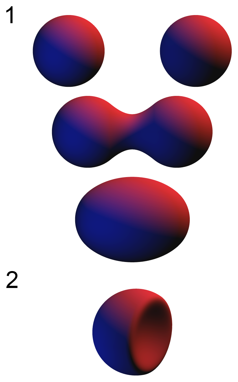
Im trying to correct this bias my 3d mesh has that a cube does not have

to the best of my knowledge, the normal vectors are the cause of the bias


I tried to correct it with custom normal vectors that were smoother
but this didnt correct the bias
so im back at square one
panzer suggested this fix in the past but I wasnt able to get his fix working at the time and still can't now
hm maybe I can google how to calculate the surface normal of a rounded SDF cube and use that
Figured it out, thank you! (needed to crate a custom clipping/dissolve effect when my object intersects a plane)
Follow up question, anyone hasa quick idea how I could fill out the whole cross-section of an object when clipping?
so that the intersection with the plane would be all white?
But that would probably mean that you'll have to raymarch
I saw this conversation going for days now, and I don't remember what is the final effect you are trying to achieve here
lots and lots of different effects all of which involve rounded cubes, at the moment my only concern is fixing this directional bias
drat, turns out what I had already was the normal vectors of a rounded sdf cube

Well, I mean, obviously a rounded cube has different normals than a regular cube, so that's why I'm trying to understand to goal of this 😅
the goal is to remove the distorted bias that the rounded cube has and a regular cube does not have

https://cdn.discordapp.com/attachments/497874081329184799/1018902110546440273/unknown.png
extreme example of the bias

Is it possible to show the rest of the graph ?
Sure but its full of custom nodes and subgraphs, 1 sec

I did not anticipate the rounded edges to give me this much trouble
Can I suggest something really dumb ?
Sure
If it looks good on a not rounded cube, but you want it rounded and the issue is normals :
What about using the rounded cube mesh, but with hard edge custom normals like on the regular cube ?
visual example of the problem, different corners scatter light differently (light direction is unchanged here)

Sure I can try that, 1 sec
hard edge custom normals


its slightly better but the bias is definitely still there
It looks like the issue is in the model's normals. Why are you trying to correct it in the shader instead of fixing the normals in the model?
Because I don't know how to do that
isnt that what im trying to do right now? replace the normals with custom ones?
Am I right to say that you end goal is to have SSS on a rounded cube ?
Is this the only thing you are trying to do here ?
Yes to the above SSS rounded cube
let me go open up 3dsmax and then google how to edit mesh normals
replacing its normals with the hard edge normals just pinches the problem

I'm giving my two cents on how I would (and already did times ago) a SS effect in shadergraph :
Simply make a custom lighting with a ramp that bleeds a bit the subsurface color in the near -0 values
Are you modifying the vertex normals or the fragment normals here?
vertex normals, is there another way?

the fragment has no normals because its not a lit shader
original mesh

Is this a model file you can share here?
Yeah sure 1 sec
the normals lol


the normals look normal in 3dsmax
granted I havce no idea what it would look like if otherwise messed up
is it maybe because of the triangulation of the mesh?

Im pretty sure it gets triangulated when imported into Unity
yes
If the light direction is really the same here, relative to the camera, then this can only be explained by wrong normals in the mesh, or something wrong in your custom shading.
You can try letting Unity generate normals instead of importing (or the other way around if they are being generated by Unity)
In the model import settings
Yup light direction doesn't change, will look into that mesh thing
is it in here somwhere?

Yes, under Geometry
ah normals - import I see
no different at all with calculated normals
ill try the various dropdown modes
Then the only thing that can explain that artifact is you're shader is somehow dealing with the object rotation incorrectly, either not taking it into account or taking it into account when it shouldn't.
Hmm okay Ill approach it from that angle and walk through the graph looking for where that value gets used
The problem doesnt occur on the default unity Cube
is there some way I can make it easier to detect the problem?

I see that you are also using the object position as input of one of the subgraphs
As it's different from the unity cube, it might come from this as it affects the rest ?
You could try to force the position value to match the one of the unity cube :
From position, take the absolute value, and then the max of each channel, and then divide the original position by this value.
Sure, 1 sec
Like this?

Yes
bias persists, though its gone on the sphere - this is without the vertex normals being changed, I can set them back to changed though

Oh, I think it will make the positions like if the cube was 2units wide, so maybe need to be divided by two
And yes, worth trying to change again the vertex normals to match the default cube
This all seems VERY hacky though, but I can't get the grasp of what your graph is doing with all the subgraphs.
Actually I was doubling my position before so I didnt have to divide, it was designed for that size
the bias still exists though even with the vertex normals and box position
so its gotta be inside the maths then
the sphere absolutely shouldnt have that dark edge if this was working right

the light has no rotation, its dead on the mesh front 0,0,0
It's very surprising then, as in theory the normal and position info should be exactly the same at this point 🤔


those are the two custom maths, everything else is nodes fed in
Oh boy, it's to late in friday for me to decipher this like that

HMM the default cube is showing tons of weirdness
but that is with the fixed vertex normals and position of the rounded cube
but at least its clearly showing some kind of directional bias there

like some part is not centered 🤔
Note that if you were already doubling the position values (with the adjustment input ?), they are probably doubled again
the old double * 2, I didnt pass this into the new values

new one just starts with non doubled

okay
Do any of you have experience with local keywords of shaders an editing them at runtime? ( https://docs.unity3d.com/Manual/shader-keywords-scripts.html )
I keep on setting renderer.material.DisableKeyword(keyword) and when I check in my C# script for renderer.material.IsKeywordEnabled(keyword) it is disabled, but when I open the material in the editor afterwards, the keyword is still enabled

Im going to experimentally normalize all my inputs just in case somewhere in there is the cause
Yes, I thought of that but didn't say it, maybe normalizing the normal value can fix some interpolation issue
renderer.material will make a copy of the material on your object, so you need to inspect the object, not the material asset
yes, I mean I checked the object in the hierarchy and expanded the material component, the checkmark is still set 😦
How exactly are you checking if the keyword is enabled on the material? The only way I know how is to change to Debug mode in the Inspector and check the keywords array there.
The shader custom editor might be using something else to set the checkmark, like a hidden shader property.


deleting the Position input removes the bias
so the Position in some way is responsible for the bias
deleting the position is not a sollution though because it borks the whole SSS without it
ah, so it is actually off, just the inspector is showing me the wrong display, thanks so much!
HMM looking at the 3 channels of the SSS in the XYZ, the bias exists before they composite together


I feel like were close to finding the source of the bias problem
aw shit I think I maybe got it

to make the SSS effect, its sampled 3 times from 3 directions
im thinking sampling from only one side is producing the bias

gif of the 3 individual channels before they are composited together
the bias is clearly coming into existence from the up/down direction, left/right doesnt have it and back/front doesnt have it
hrmg
I tried messing with all the inputs to that node
but none of them removed the bias, despite the bias coming out from its result
none of them affected the bias in any way that I could tell
setting exerimental values, it looks like maybe the bias comes from "subsurface" so Ill go back to that step to see what I can change there


I found the source maybe
this swizzle, when changed, its the only thing so far that has affected the bias position
the problem is even more noticeable if I send in the custom normals

the purpose of the swizzle was to aim the effect to its 3 sides, but that only worked on a real cube
Ill see if I can replace it somehow 🤔
Quad at the intersection that's clipped inversely via stencils perhaps

I have to get lunch - do you know some way I can get Axis A and B without swizzling the normal vector?
the swizzle was done as a cheap way to get the two axis but its introducing errors so I need a better way to get the two axis
you could probably just swap them for the tangent vector and the other one (bitangent?)
like this?

axisA = tangent, axisB = bitangent basically
oh no cross product?
they're already perpendicular to one another and perpendicular to the normal (and hopefully aligned with the faces) which is all we need
That makes sense, yeah swapping those in it works perfectly now, no weird bias 👍


amazing :)
ok i got the depth color gradient thing working

but now the tutorial is going on to textures with waves
i'm not sure i want that particular effect...
this tutorial video that is
the tutorial goes on to make nice realistic style wavy waves
i was hoping just to achieve this mild water movement effect 👆
i don't know if that's also vertex normals effect?... maybe it's something else?
@karmic hatch you around maybe? 😉 🙏
Using textures to make waves is pretty standard, just changing the fragment normals using a wave normal map.
is that what looks like is happening in my reference clip?
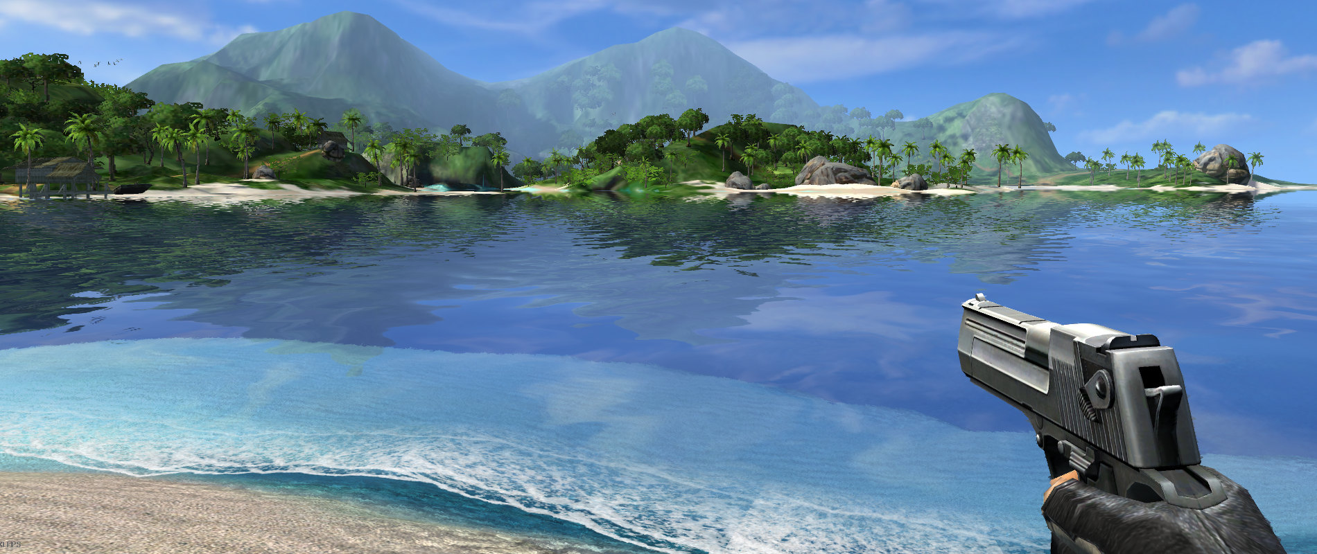
that water i'm referring to is very clear blue and quite "calm", all you see is reflection of surrounding scenery, and the small waviness i guess which might be this normals effect thing. the water is very smooth and "shiny". i think the Boat Attack water is aiming for a lot more realistic with bigger waves and lots of foaminess in the moving textures, or something, not what i'm trying to achieve
The main difference between the waves will just be what textures you use
i see
Since the waves are small you can just use the normals to fake a 3D ripple effect
ok so i should still follow the tutorial video? trying to figure out where do i need to deviate in order to achieve my desired effect
right, i dont really need vertex displacement or anything like that at all, right?
👌
will prolly need to get some clue which parts do i need and which parts do i not need... lemme just try to follow the video tutorial for now and i'll let you know when i'm not happy 😛
(sorry for asking again - video says "...achieve this effect by making 2 normal maps moving in different directions..." - is that what's happening in the reference clip?.. meanwhile will proceed trying to make it as shown...)
yes, having two moving in different directions means you can avoid much of the grid effect and the waves appear to change shape over time
ah ok
the video is showing to select "Type: Bump" on the Texture2Ds but seems that setting no longer exists
maybe it's something else now?
Just use a normal map
what are you going to do with the texture? Put it on a material?
Just importing it as default (Texture2D) should work
ok
now in the video it's showing that it's selecting 2 textures into the editor placeholders
this is where i am not happy 😛 i don't like the tutorials waves, i want more like my clip
you;d have to be more specific about what you're talking about because... IDK what you are talking about
this tutorial video i am right now trying to follow 👆
this clip 👆 is the exact type of water effect i am hoping to achieve as exactly as possible
Just look up "ripple normal map" or similar, and then download some and see how they look
ok lemme try that
i mostly don't know what i'm talking about, but - can't this kind of mild ripple normal map be generated within the shader itself?...
or is that too expensive
another question is; in the Unity tutorial water the goal seems to be to give the water some texture, however in my reference clip it seems to affect the shape of the reflected environment, i.e. the water itself is shiny smooth crystal clear, dont care for no texture of its own. Just want it to 1) reflect surrounding environment, and with that 2) just very mildly ripple the water around, but that only affects the appearance/distortion of the reflections, no "texture" of the water itself
if that makes any sense at all...
yes, but it'd probably also be more expensive than sampling a texture
ok gotcha about that
if the normals change fairly rapidly then that gives you the effect of rougher water, if they change smoothly and slowly then you get quiet ripples
you could set the blue color from the water as emission and then it wouldn't be affected by normals
hm ok, do i need that? hoping not to sound too repetitive & dumb but - does it seem like that's how it works in my reference clip?
In your clip it looks like the lighting is high enough up that it wouldn't matter, but if you want sunsets it'd probably look a bit weird if some of the water is properly in shadow
Hi guys,
I'm testing Dots on the Quest 2. I was wondering: does Hybrid Render supports Quest 2? From my googling it seems it doesn't yet but I'm not sure...
OK so i got.... something. but it just looks exactly like 2 textures sliding across each other. how can i see how this affects scene reflection?

i'm starting to think maybe my reference clip might have a different effect, not really textures... there's some sort of dynamic twisting turning & distorting happening, not just textures sliding around like i have here:
compare with 👆 (full screen, examine closely)
can you try using smoother normal maps, eg


@karmic hatch hey hey hey it's starting to look pretty close actually 🤩 approaching the desired effect
also did the smoothness part of the water tutorial, that also added a lot towards achieving the desired effect
thanks for those normal maps
i'm using the 1st one
Hello lovely Unity People:)
I'm new here so I'd like to introduce myself. I'm Chris from our small company celrage from bavaria, germany and I work as a software engineer. My new focus is shaders, and there is my problem:
when I use this hlsl code I only get always 1 as a return (white) when it should have a gradient when using point light:
`#include "UnityCG.cginc"
#include "Lighting.cginc"
#include "AutoLight.cginc"
#define USE_LIGHTING
#define UNITY_HALF_PRECISION_FRAGMENT_SHADER_REGISTERS
struct mesh_data
{
float4 vertex : POSITION;
float3 normal : NORMAL;
float2 uv : TEXCOORD0;
};
struct interpolator
{
float4 vertex : SV_POSITION;
float2 uv : TEXCOORD0;
float3 normal: TEXCOORD1;
float3 world_pos: TEXCOORD2;
};
sampler2D main_tex;
float4 main_tex_ST;
float gloss;
float4 _color;
interpolator vert (mesh_data v)
{
interpolator o;
o.vertex = UnityObjectToClipPos(v.vertex);
o.uv = TRANSFORM_TEX(v.uv, main_tex);
o.normal = UnityObjectToWorldNormal(normalize(v.normal));
o.world_pos = mul(unity_ObjectToWorld, v.vertex);
TRANSFER_VERTEX_TO_FRAGMENT(o); //lighting, actually
return o;
}
float4 frag (interpolator i) : SV_Target
{
return LIGHT_ATTENUATION(i);
}`
What do I do wrong?
Thank you for helping:)
@karmic hatch next step in that video tutorial is water motion by vertex displacement, so i think i'm gonna skip that part. Seems like this is how far that tutorial goes, what's next step - how can i make the awesome scene reflections on water? is that using something like cubemap? reflection probes? render to texture? other?
I think reflection probes bake a cubemap storing the reflection data but I haven't used them before so I'm not too sure on how they work
ah ok
can you tell me this though: when looking at water and seeing distant graphics reflected on the water, and it looks like it's moving and distorting along with the "mild waves", is that already in place with these normal maps? or does that need some additional effect
i'm still doubting whether the normal maps is what's gonna help achieve the effect i'm hoping for, or if normal maps are all about the water "texture" but what i need is some other water distortion effect which will also do the right thing when reflecting the scene... (but i still hardly know what i'm talking about so i'm probably completely wrong)
still - this is already very very much on the right path 🤩 🙌
side by side 🤩
This looks like screenspace reflection
also just for information/education sake; as opposed to what? are both equally viable approaches, if done in screenspace or otherwise? difference in quality / correctness of the appearence? difference in performance?
or it's just that - this effect must happen and can only work in screenspace
Screenspace reflection means taking what has been rendered on screen, flipping it vertically and adding distortion to it, so it looks like a reflection. There are built-in solutions for this.
Alternatives would be to use a reflection probe/cubemap, either pre-baked or realtime. Prebaked has the problem of not being exactly from the point of view of the player in most cases, so the reflection won't look right and realtime is expensive, because you need to render the scene multiple times.
Actually, taking another look, it looks like this is a cubemap, rendered separately. I say that because I can tell in the reflection that some elements are missing in the reflection, like the vegetation
URP lit shader. What blend type does the colour picker use to add colour to the albedo texture?
The documentation doesn't specify whether it's overlay or multiply, or maybe something else.

math question 🤔
this SDF function takes in position, bounds, and roundness to return a rounded cube
The issue im having with it is that both roundness and bounds cause the cube to grow/shrink in size.
its very frustrating to try to adjust the shape when they both make it bigger/smaller
What formula can I perform that will make one relative to the other?

Ive tried dividing one by the other and using that but it hasnt worked thusfar
im constantly fighting against it to get the shape I want
it also doesnt help that the values only seem to work in like the 0.01 range

gif example of what I mean, trying to adjust the radius of the roundness and the size of the effect BOTH make it bigger/smaller so its a struggle to make minute adjustments

I want to be able to adjust the roundness without the black changing

still doesnt work right with the divide
its better but not right
also doesnt work

there are only two floats and one divide, there are only so many possible arrangements of plug in
but I cant find the correct arrangement
no matter what arrangement I use, it constantly floods white or black :/

giving up for tonight, I cant solve this
I want at least one of the values to be static
like by that I mean
I want the value to not change when the other value changes
or rather it DOES change, and that change counteracts the rescaling that the other value causes
I want to be able to scrub both values and not lose the size of the box
which currently I cant scrub either value without immediately losing the size of the box
Since they're talking about tint, it's a multiply. And traditionally that's been the default in the code.
But the color picker doesn't do it, technically, it's all on you in shader code. You can do whatever you want, is what I'm trying to say...all depends on what YOU do, the color value is just a value passed in.
It's not a blend type in terms of, say, blending transparents. It's a color-calc for the current pixel only, not for blending with the background. Blending the final result for the current pixel, including alpha, with the background is yet another step/setting.
@leaden turretYeah, MS is correct, IMO.
Cube maps produced by the reflection probes are not too bad IF you can tolerate low res versions, and you spread each cube face out over time/frames. Then you combine your surface normals and decide on a reflection angle, using that to sample the cube map.
Alright I feel like this is a basic thing I'm goofing. I want to tint the pixels towards a certain color while giving them a bit of bloom, but often these regions just end up completely white. What's the correct way to do this?
Thankyou for the info that it is multiply. I'm not talking about a shader graph or custom shader code; The default URP lit shader. Many image editing software's refer to the way image layers interact as blend mode which include multiply, overlay, etc. I believe unity shader graph has a blend node as well which has many options of blend type.
Try subtracting the roundness from the bounds?
I think the bounds creates a cube, and then the roundness says 'any point within [roundness] radius of that cube is part of the rounded cube'
Though it may work slightly differently, eg having roundness as a fraction of bounds (so then you'd want to multiply bounds by 1/(1 + roundness))
I've noticed that when you tint something through multiplication the end result tends to be darker.
How do you... prevent this?
Colors are in 0-1 range, multiplication of two values below 1 will only result in values which are lesser or equal to the smaller value
So, use something else besides multiplication or multiply by a value above 1
Well they can be treated like vectors no? Couldn't I extend the result of the multiplication to match the length of one of the original colors?
I suppose
You can use all the blend modes and math out there if you're not restricted to multiplication
UR Welcome.
You're asking about two things at the same time.
The color swatch is a multiply thing. It impacts the current pixel color as a tint.
Layering and blend modes is a blending thing, regardless of color swatches. It's about how the results are applied over top of existing background.
The shaders have both types of options at the same time.
🙂
Are the results from the two not the same? I thought the colour picker multiped by the albedo texture would have the same reuslt as the same colour multipled by the same texture with a blending mode
One of the colors? Like the "longest/highest" one? Maybe.
The thing is that the human eye doesn't see all colors being equal in intensity, it is more sensitive to green. Green gets more "oomph" in the various brightness/luminosity calcs.
Tinting can remove colors completely too. What if you take a pure-green (0,1,0) and "tint" it by multiplying with pure-purple (1,0,1)? lol. It's black. That's why whatever you tint with should usually have some white-ish it in at some level (some degree of all three values).
The blending result CAN be a multiply, but it can be many other things too as you noted.
the color swatch thing, though, is always a multiply in the default shaders.
And the layer-blending is weighted by alpha coverage.
Anyway, blend mode and color swatch are two different things in the shaders. Just FYI.
Yeah cool. Thanks for the clarification. I thought you meant I was talking about different things. I get that the URP lit shader doesn't have options for blend modes! I just wasn't sure which it used 🙂
I didn't know about colour swatch was a node in SG
That will be useful to know. Ty
It DOES have the option, but probably only with transparency.
IDK if it is a node or not, but it is simply a multiply before you plug into base color.
Okay so shader graph equivilent is a colour node into a multiply node with albedo, into base colour?
You could put "Tint Color" on the blackboard and call it _BaseColor
Yeah. You'd have some color thing on the blackboard, name it _BaseColor, and maybe a texture thing on the blackboard called _MainTex or whatever the hell the default for URP is, and then you'd multiply them with a multiply node and put the result in the albedo.
Yeah okay cool. I wasn't sure if you were saying that blend multiply and math multiply node were different or not
But if it is a transparent shader, you'd also set the blend mode as ANOTHER option.
That sounds like a 2nd blend node to me
I meant mode, not node. lol. Sorry, edited.
Ahh
Play around with it. Have some fun experimenting, great way to learn.
Yeah nah, still. For context, I'm using b/w textures for detail, and then I'll use the colour node to give them their colour of the color palette needed for the game
Thanks I will
That's the right way to do that! Yep. The B/W color basically represents an intensity multiplied by the actual color you want.
You might even experiment with a vector multiply using only ONE channel from your B/W texture. IDK if the full vector multiply is slower than a single-value multiply that is applied to all 3 channels. IDK if you can even benchmark it. But you'd only need one of the 3 channels for the result. In fact, once you edit them you can use a one-channel texture (like a red-only channel). Saves memory and bandwidth.
How can I use a compute shader to get a list of pixels in an image? I've found that it's not as simple as using id.x and id.y
RWTexture2D<float4> Result;
AppendStructuredBuffer<float2> pixels;
float r;
float g;
float b;

[numthreads(8,8,1)]
void CSMain (uint3 id : SV_DispatchThreadID)
{
    if (length((Result[id.xy] * 255) - float4(r, g, b, 255)) < 0.98)
    {
        pixels.Append(float2(id.x, id.y));
    }
}
IDK what that if statement is doing, but it should be that simple...if you sample the texture and output the list into another structure like a structured buffer of type append if that's what you want.
@dense dawn
Ah the if statement is just checking if the colour of the pixel matches a given colour
You need to sample the texture though.
Sorry, what do you mean by sample?
Maybe I'm wrong, maybe you can just read it that way. Hang on.
Hi! I'm fairly noob in shaders and would really appreciate some help.
I have a paid asset which I'd like to modify (as less as possible), so I'm bound to it's own logic. I'm on built-in render pipeline so no graph node.
The shader can take an overlay texture and basically merge the colors of the main texture and the overlay texture to create a a crossfade over time. The problem is, I have both the main and the overlay texture in atlases (different ones) and would need to specify the UV for the overlay texture.
The shader provides an overlay texture (_OverlayTex) and float min/max x/y (u,v) values (_MinXUV, _MaxXUV, etc) that I can set from c# code. I figured I could use the latter values to set the UV boundaries for the overlay texture as follows:
  // sprite is the overlay sprite here
  Rect r = sprite.textureRect;
            r.x /= sprite.texture.width;
            r.width /= sprite.texture.width;
            r.y /= sprite.texture.height;
            r.height /= sprite.texture.height;

 renderer.material.SetFloat(minXUVId, r.xMin);
            renderer.material.SetFloat(maxXUVId, r.xMax);
            renderer.material.SetFloat(minYUVId, r.yMin);
            renderer.material.SetFloat(maxYUVId, r.yMax);
// example result: x-: 0, x+: 0.125, y-: 0, y+: 0.125
In the shader's frag it multiplies the colors of the original and the overlay texture like this:
half4 col = tex2D(_MainTex, i.uv)
[...]
half4 overlayCol = tex2D(_OverlayTex, TRANSFORM_TEX(i.uv, _OverlayTex)); // <-- this is where I'd need to use the overlay's UVs instead of i.UV whic his for the main tex
[...]
col = lerp(col, overlayCol, _OverlayBlend);
How can I use those float variables to get the correct UV for the overlay texture here?
You probably can't, id.x and id.y give me values that are far larger than the actual width and length of the image
I think it's SourceTexture[float2(x, y)]
and you should bounds-check x and y.
or
SourceTexture[id.xy]
Which is what you have.
So ...
I'm confused. Should work.
are r, g, b 0 to 255?
They are, yes, which is why I multiply Result[id.xy] by 255, the if statement should work as I use the exact same on in another (working) compute shader
What I'm trying to do is get the x and y of the pixels of the specified colour, but it gives me x values that are like 10000 when the width is only 5000
id.x might be the only part of the thread id that matters
you may have to do something like:
uint x = id.x / width;
uint y = id.x % width;```Ah I see, I'll give it a go
grabPixels.Dispatch(0, provinceMap.width / 8, provinceMap.height / 8, 1);
Unfortunately it gives me this

what am I looking at here?
Is that id?
for each thread?
It's the resulting pixels list that is appended to in the shader
It correctly gets the number of pixels, just not their x and y
line 2
Well THAT helps to know, you're finding the pixels. It's your appending of data to the structured buffer that isn't working? Makes more sense now.
Yes, sorry I didn't make it clear, it just appears that the incorrect x and y is being appended for each pixel
I am so stupid, nothing is wrong with the shader
I originally got the pixels at 1/4 the resolution and then multiplied it by 4, but at some point I changed to the full resolution, but still multiplied the resulting pixels by 4
Just saw the sneaky little * 4
Thank you both for trying to help me
I'll flag up @edgy vine 's question now because I buried it with mine
TRANSFORM_TEX is a macro that applies the scale and offset values you see in the inspector to a non-atlased uv. It's messing with the UV's.
You have an atlas, so the UV's are different anyway. So assuming you're not using the scale/offset in the inspector, you can replace that and do the atlas calc instead (I think...I don't have your shader).
The atlas calc is simple if you know the location of the sprite in the atlas (which I think you can get from C# and pass it in).
You just lerp using the 0-1 range UV's
newuv.x = lerp(xmin, xmax, uv.x);
newuv.y = lerp(ymin. ymax, uv.y);```@meager pelican Thanks! This is what I tried as well but with no success. Well, the textures are the same size so I guess it shouldn't matter if uv.x/y (i.uv) are for the main tex, right? I first thought it should not matter because uv.x-y are generally between 0-1 so with the correct min-max lerped (coming from the set floats that are for the overlay texture) it should return the correct pixel from the appropriate texture from the sprite (the atlas). But it doesn't seem to work and I'm pretty sure I'm missing something obvious.
Performance Q,
If I have a thousand particles drawn on screen that take about 20% of the screen, or 1 large cube that takes up the remaining 80% of the screen, if both are using the same lighting model, the cube will be more expensive to draw, is that correct?
My understanding is that the whole thing will be rasterized and then it basically comes down to what calculations are involved for each fragments, independent of the complexity of the objects. So if they're both using the same lighting model, then the object that represents a higher count of fragments is the most expensive to draw. Is that a correct assumption?
I do understand(or at least I believe) that the rasterization process itself is more expensive for more complex objects. What I'm mainly interested in knowing is if there is any other overhead for more complex objects other than rasterization, or if the above stands true
Thats hard to answer as theres so many factors that can affect the performance. Its good to note that usually particles uses transparent shader meaning they cant take use of z testing. Same pixel may be rendered many times, ones for each particle. Opaque geometry can optimized using z testing so most of the unnecessary rendering can be skipped (transparent geometry may be bit slower to render in general as theres things like blending to be taken into account)
Im trying to change the vertices from a skinned mesh but I think the animation is adding some transformation at the end
compute shader code
// Each #kernel tells which function to compile; you can have many kernels
#pragma kernel TriangleParticle

RWByteAddressBuffer bufVertices;
RWByteAddressBuffer bufIndices;
StructuredBuffer<float3> bufOldVertices;

float triDist;
float trilerp;
float time;
float3 target;

[numthreads(64,1,1)]
void TriangleParticle (uint3 id : SV_DispatchThreadID)
{
    int index1 = bufIndices.Load((id.x * 3) * 4);
    int index2 = bufIndices.Load((id.x * 3 + 1) * 4);
    int index3 = bufIndices.Load((id.x * 3 + 2) * 4);

    float3 tri1 = bufOldVertices[index1];
    float3 tri2 = bufOldVertices[index2];
    float3 tri3 = bufOldVertices[index3];

    float3 newTri1 = tri1 + float3(0, trilerp, 0);
    float3 newTri2 = tri2 + float3(0, trilerp, 0);
    float3 newTri3 = tri3 + float3(0, trilerp, 0);

    bufVertices.Store3(index1 * 40, asuint(newTri1));
    bufVertices.Store3(index2 * 40, asuint(newTri2));
    bufVertices.Store3(index3 * 40, asuint(newTri3));
}
how would I go about removing the transformation at the end???
I know that the transformation is the animation itself but how would I go about moving the whole thing as whole
Is there pixel shader of some kind
void rayBoxDst_float(float3 boundsMin, float3 boundsMax, float3 rayOrigin, float3 invRaydir, out float dstInsideBox, out float dstToBox)
{
    // SDF Cube with Rounded Corners
    float3 q = abs(p) - b;
    Out = length(max(q,0.0)) + min(max(q.x,max(q.y,q.z)),0.0) - r;

    // Ray Box Distance
    // Adapted from: http://jcgt.org/published/0007/03/04/
    float3 t0 = (boundsMin - rayOrigin) * invRaydir;
    float3 t1 = (boundsMax - rayOrigin) * invRaydir;
    float3 tmin = min(t0, t1);
    float3 tmax = max(t0, t1);

    float dstA = max(max(tmin.x, tmin.y), tmin.z);
    float dstB = min(tmax.x, min(tmax.y, tmax.z));

    dstToBox = max(0, dstA);
    dstInsideBox = max(0, dstB - dstToBox);
}```
Would it be nontrivial to convert this ray box distance formula to work with a box with rounded corners, instead of a perfectly cubic box?no its just the compute shader
the ray box version works off of min and max and assumes a linear gradient of values between them, which would no longer be the case 🤔
hm maybe I could multiply the result by the rounded box??
ah mult doesnt work because the rounded box version has no concept of depth

hm wait I think I can do this 🤔
darn nope, I was thinking I could pass in the rounded UVW as the min and max

but that is not how that works
looks like this will require complex code instead
Hey everyone. I'm trying to make a health bar with rounded sides that floats above my characters via the Shader Graph. See the white bar for reference. I can make it look like that using a prefab with a quad in it and a rounded rectangle node in the shader graph that's been sized just right, but if I scale the length out on the Rect Transform property to make the bar longer for large characters the sides begin to point instead of keeping that nice perfect half-circle look. How can I get that shape procedurally and allow it to scale longer or shorter without distorting?

Debug question 🤔
Distance To Box is the max of Distance A and zero
When output this works as expected
but if you calc it outside of the node, it is pure white for some reason?
What is different here?

oh the answer is that Im dumb
the output is not actually what it says it is, order is mixed up
🤔 very interesting passing in the object coordinates instead of a flat value


neat but not quite what I was trying to obtain
Im positive I can get rounded edges if I just knew what to input for the min and max
if 0.5 and -0.5 is a perfect square, how do I adjust those values so that at corners its rounded 🤔
I hate how stupid I am, i just blindly try things with no idea until it either works or I go into crisis
i lack comprehension of anything

its not rounded edges but I did manage to slightly bend it

neat but not this
I cant solve it

if this is the product of (0.5, 0.5, 0.5) and the same but negative -0.5
but its the same value at every position
but somehow that makes a cube
and somehow Im trying to adjust it to be round
I hate that I cant figure it out
why cant I just figure it out
why do I have to be so fucking stupid
It's not that no one is interested but some people got no clue either, or just don't see it like a time wasted well, maybe formulate the things better, think about it more than just brute forcing it all the way through
Being smart doesn't make missing knowledge manifest automatically either
Most of shader stuff is just knowledge
To give any kind of opinion on your projects I'd have to study a whole lot more about geometry and math first
do you want the depth through a rounded cube?
ye just practising formalising a problem in terms of equations and then solving them
takes some work to develop intuitions for how to solve problems but it's very useful
I would likewise lose my mind if I tried to force myself to solve problems way beyond my current skills, so I stick to simple stuff and build up gradually
Also with shaders having it be exact is nice but the goal is almost never having it be exactly right, if it looks close enough, it is close enough, so often you can fudge a hard problem into an easier one, or even throw away finding a proper solution to any problem and just mess around until something looks good
my guess for an exact solution to this problem would be to get the signed distance function for a rounded cube (the raymarching guys have it), then say the signed distance function equals zero, which imposes constraints on how far the ray must be from the camera (vector equation of a ray is p + vd, where v is the view direction (going out from the camera, i think shader convention is usually going into the camera), p is the camera position, d is the distance (scalar)). Then hopefully that is a quadratic or something otherwise pleasant that can be solved easily
How do you want to show it? Just scale the length, or is that two colored, or what?
Anyway, as a guess I'd try two points and a radius. The radius determines the thickness of the bar, and the distance between the two points represents the "straight" part of the bar, with the rounded corners to the left and right of the points.
You can use a distance function to round it off if > radius, or you can decide if you're "in the middle" in which case the Y value is the center +/- the radius and the x moves between the two points. The left end x is the 1st point - radius and the right end is the 2nd point + radius, all limited by distance to point.
You could use a custom function I suppose.
And you might be able to calc the two points in the function from the radius, and just use UV's from a quad.
trying to do some fluid rendering, and need to grab the depth of a vertex's position, which means i somehow need to convert that to a uv4 it appears, is there any way to do this?
uv is 2d texture mapping. It's % across the texture in x and y.
You want depth of vertex POSITION?
yes i think so
float4
ye but how do i plug that into the scene depth node then?
So, do you want this in the vertex stage or the fragment stage?
not entirely certain, i think fragment though (can shadergraph do the fragment stage?)
OK, scene depth node is the depth of the BACKGROUND, not the current pixel. Is that what you want?
ah no, im looking for some way to get the depth of a vertex as a colour somewhere between absolute white and absolute black
yes it does/can do frag, that's the norm in fact.
OK, so you want to basically have a scene depth in grey scale, if you were to show that as a result, for what is being rendered at the moment. That's not really the scene depth node, unless you're in a post process shader.
You want some kind of depth. You say vertex, but in the fragment it's not a vert it is a frag....not being picky, just precise.
So I think you want the current pixel's depth. There's different ways to express depth. In a 0-1 value as distance to the far plane and then there's world space units.
ah yes, pixel's depth should work, im happy for either of those options
im trying to do bilateral filtering, so it blurs edges that are near to eachother but leaves edges far away from eachother nice and sharp, it uses depth for this to calculate if the edges are touching
https://docs.unity3d.com/Packages/com.unity.shadergraph@7.1/manual/Position-Node.html
Maybe view space depth will work for your use case.
ill try it out, thanks!
If you need it as a post process (across all objects after they're drawn), you can use scene depth node. It has settings for the type of result.
i kinda completely forgot post processing existed, but that could actually work better, ill look into that
Interesting, thank you! Is that something specific to particle systems or are you stating that by default, built-in particles shaders use transparency? My PS material uses a shader that is basically an unlit graph with a texture/alpha clipping. I was under that assumption that it did benefit from z testing, and also GPU instancing which wasn't offered on URP default particles shaders.
Now that I think of it, there was probably a reason for that. Anyway, would you happen to know if those assumptions are correct?
hey @low lichen @meager pelican sorry I had to run last night... scrolling back now to follow up on how to implement those water reflections
@hearty obsidian @dim yoke Sorry to butt in, but like @dim yoke said there's a ton of variables. Just having transparency can impact things because different GPU architectures on your target platforms will process differently, to name only one thing.
My guess is that you're going to have to write it both ways and benchmark results, I'm afraid.
butt in all you want, the more info the better
Hm, well do particle systems using meshes for rendering behave like a typical mesh, in the sense that they will benefit from ztesting provided they are using an opaque shader?
ok i have gotten the depth thing working, now i need some way to render my vertex's as spheres, im happy to either do this on the fragment by creating a circle around the screenspace's position of the vertex, or do this on the vertex stage by creating sphere geometry there, which do you think would be easier?
Yeah thats what I was trying to do before getting too emotional to think clearly
Head cleared now
Yes. Early z testing happens with particles too. Transparent and opaque. The thing with transparent is in what order it is drawn in, and how it combines with what is behind it, and of course it doesn't update the depth buffer so other transparent things can be a problem. But if, say, a tree that was drawn close to the camera in the opaque pass is showing, and the particles are behind it, they'll be clipped by early-z testing.
@meager pelican Awesome! Are particles written to the depth buffer if using an opaque shader? If so, say there are overlapping particles all belonging to one system, I suppose it'll be drawn as a single mesh, will particles in the back be clipped?
Ouch, that's tough.
You're asking about individual polygon draw order on a complex mesh and I'm not sure of the answer.
They CAN be written to update the depth buffer, sure. That's the default in opaque. Been a while since I've written a particle shader. What particle system are you using?
Built in, does that help?
@meager pelican any chance this article about those water reflections gives any additional hints about how they work? https://cookieplmonster.github.io/2018/07/07/farcry-d3d9-bug/
Silent’s Blog
How water reflections revealed a regression in D3D9 - and how it was fixed!
So I think that's still Shuriken? Anyway, not VFX.
Most of the work is done on the C# side with a relatively simple vertex color shader for the particles. That's not to say all particle tasks are easy.
@meager pelican Aye shuriken, game's in production I figured this wasn't the best time to starting learning VFX graphs.
Okay, well built in PS allows the assignment of a material so I'm going to work under the assumption that ztesting is working fine, as it seems to be OK right now
Thank you for your help!
not certain if this is best for a vertex shader or whether i should just manually do this in c#, but i need to be able to convert every vertex into a sphere so that my fragment shader can then draw stuff properly, should i use the vertex side, or just do this in c#
OK. Generalization.
When drawing a mesh, you're only dealing with the fragments covered by the mesh itself...nothing outside of it is being output (although you might READ values from the background or whatever other textures you have).
Is the only way to create an egde outline shader is by using post process?
Is this for game-time, or editor tools?
@low lichen maybe indeed my clip was from a patched version of the buggy render on Windows 10, whereas the real thing looks like it does render vegetation?

No, but it depends on if you want to outline triangle/polygon edges or the resulting edges without the diagonals of the polygons drawn. Like there are wireframe shaders. But otherwise you'll need all the polygons drawn first, so you end up in PP.
Some, but not really relevant to what I think you're doing as you would be using modern techniques.
ah i was hoping to find out that some technique they were doing back in 2004 is soo outdated and now i can achieve a similar/better effect with much more performant technique
Like you want to put dots on the verts?
unfortunate, my mesh is a series of points, no faces, no lines, created each physic frame from nvidia flex (fluid simulation stuff)
dots or spheres or something i can draw on in the fragment section
Use a particle system with locations as defined on the mesh verts?
Use a small round-image quad maybe, or a sphere mesh.
im afraid i dont quite understand, wouldnt that make every point a seperate mesh?
yes but then the shader would apply individually to each of them, instead of all at once, which is kind of what i need to do bilateral filtering i think
Oh.
ye im kinda in a no win situation
So let me see.
You want to bilateral filter the entire screen image?
And you want to add dots on top of verts while you're at it?
i want to bilateral filter all fluid particles, it appears the easiest way is using spheres all on the same mesh
i have the fluid particle's positions, but i lack the knowledge of how to convert these into a single mesh of spheres
I'm guessing here but maybe you want metaballs.
https://en.wikipedia.org/wiki/Metaballs
In computer graphics, metaballs are organic-looking n-dimensional isosurfaces, characterised by their ability to meld together when in close proximity to create single, contiguous objects.
In solid modelling, polygon meshes are commonly used. In certain instances, however, metaballs are superior. A metaball's "blobby" appearance makes them versa...
metaballs are way too computationally expensive for the amount of fluid im trying to render real time, so im taking the approach nvidia suggests and using screen space blurring of spheres to do it much faster
@meager pelican would love to get started on this, any chance there's a 3hr step-by-step tutorial on how to do exactly this?
OK, I get it. That article explains it better than I can, with code. Great article, I've saved the link.
But IDK what to tell you, they don't use a mesh really. It's all screen-space depth buffer tricks and a render texture from what I see. They're passing positions to a point-sprite system rending round quads, and I think at first glance the quads have a normal texture on them. So could be done with a custom particle shader. But it isn't a giant mesh.
oh that makes a lot more sense then, thanks a ton!
Well, the sample shader code in the unity docs samples a cube map for reflections.....
remind me what pipeline you're in....
URP
targeting mobile so i'm using URP "performant" quality, aiming for as-good-quality-as-possible at best performance on mobile
Can anyone think of anything that could cause a texture to be nullified post assignment on first launch?
e.g. texture is assigned within start
material is rendered with said texture
bam texture disappears
there is no other ref to the material, nothing is nullifying that texture in the codebase
doesn't happen on subsequent scene loads
https://www.youtube.com/watch?v=943P0dGR4rQ
????
A bit old, but that's reflection. Just some quick google fu. Haven't watched it, theory should apply.
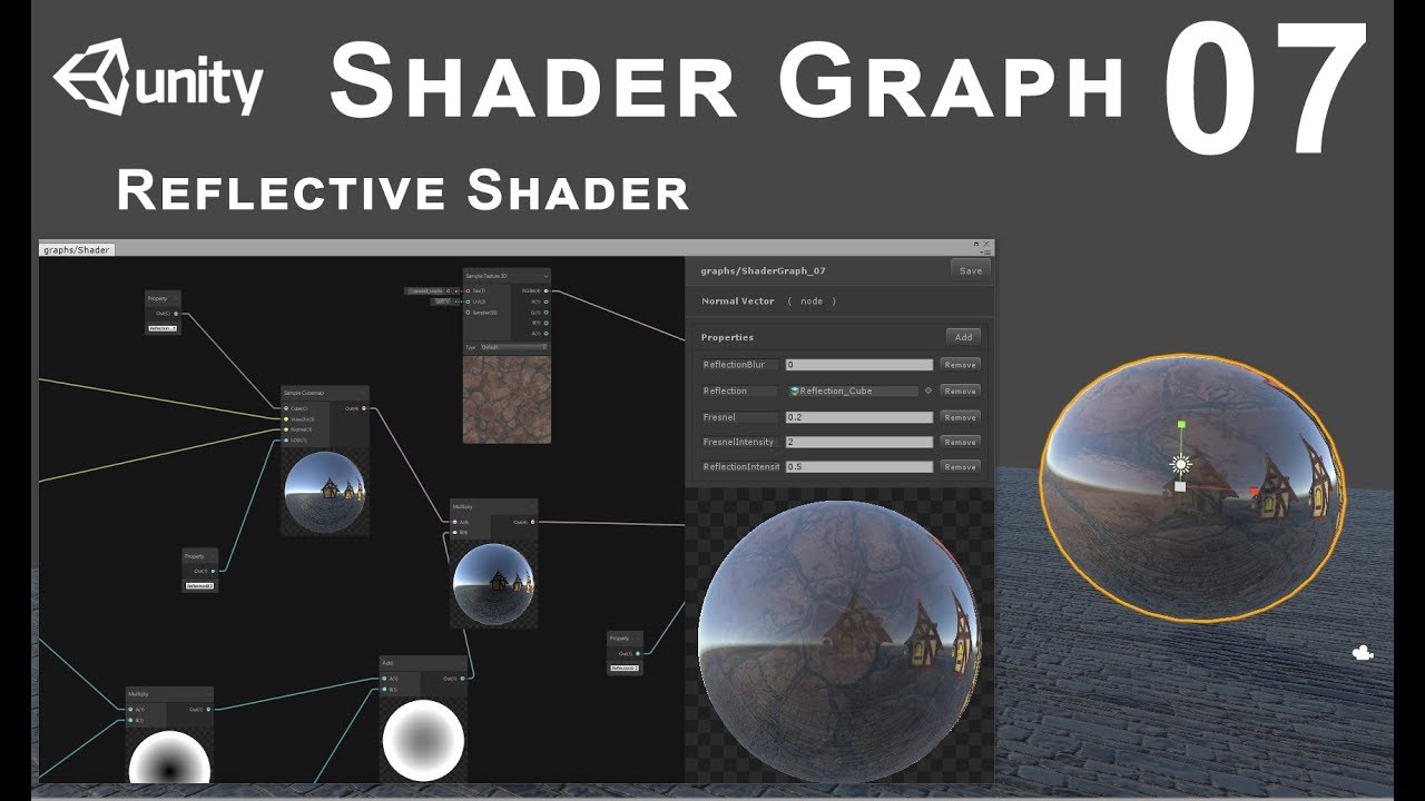
In this tutorial we'll see how to make reflective shader for static objects
ok great thanks lemme try that
reflection probes are not too bad IF you can tolerate low res versions
i think since i'm targetting mobile then indeed lower res might look just fine
If you're on mobile, I'm surprised you can afford to do much reflection at all. I mean, there's quite a range of mobile though, so it depends. High-end mobile, sure.
Basically, each reflection probe redraws the scene 6 times...once per side of the cube map. So you spread that across 6 frames, but you still have to re-render the scene, so you do it in low-res, and maybe use layers to filter out stuff that doesn't reflect.
hm
well technically i was hoping / trying / aiming to target even lower end devices... to whatever extent at all possible....
All I can tell you is benchmark it, or maybe you can pre-bake stuff.
yes pre-baked sounds good, no? sounds like it would massively reduce the computation of doing it live?
what would be the main differences/pros/cons of doing it live vs. pre baking
Moving things don't work right with baked probes.
ahh....
wait you mean if there's a moving object in scene then that doesnt work good, right?
but if my scene is mostly (almost completely) all about static environment stuff, then actually it might be very much a viable option i should think?
Yes! 🙂
awesome
i really can't think of any significant gameplay situation where i really need something moving to be nicely reflected by the water...
maybe a passing speedboat or something...
dare i guess that - i can use baked reflection stuff for 99% of the scene, and for the occasional need of a passing floating or hovering object (helicopter flying off in the distance above the water maybe?...) then i can add live-generated reflection of those specific objects superimposed upon the baked reflections?....
or that doesnt make sense
IDK an easy way to do that. You can 'blend probes' so maybe you could have a dynamic probe turned on or off or something, but I haven't tried it so I'm talking out my butt here.
Adding an image on top of a static probe still means you'd have to generate that image so why have the static one? Maybe....
ah
so maybe if i need something reflected live - then for that occasional while i might switch to live reflection, then when not needed anymore switch back to static or something like that?
i'm pretty sure 90%+ of the time i will not direly need runtime stuff being reflected on water
maybe even 95% or 98%
ok cool
@meager pelican just to make sure i'm on the right track 1) the correct way how to make my water have scene reflections (in this case from a pre-baked static reflection probe (which is basically a cubemap?)) is via the shader? i.e. i need to add the effect into the water's shader graph, that's the way to do it? 2) that youtube tutorial you linked shows how to in fact do that stuff in shader graph?
this is my water shader so far, how to figure out where does the reflection stuff fit in?..

theory not working for me yet... i'm trying to follow his first step of basically plug a Sample Cubemap into master node Emission. everything goes super bright white/yellow, not seeing my previous water with normal maps effects..
trying for the first time to use a compute shader, and it appears to use render textures with them they need to have random write enabled, how do i enable this?
https://www.shadertoy.com/view/WlSXRW Does this have the answer maybe?
https://math.stackexchange.com/questions/500394/distance-to-the-edge-of-a-rounded-rectangle hm or maybe this


Mathematics Stack Exchange
I'm trying to figure out a formula to create a rounded rectangle... but I need to do it by finding the distance from $(0, 0)$ to the line/edge of the rectangle given the angle provided as a vector....
thinking about it, a rounded rectangle is just a sphere that has been extruded 🤔
you can collapse a rounded rectangle back into a sphere by removing the parts that arent just the corners
Is it possible to combine normal mapping with reflection probes to get visible surface detail in areas where an avatar isn't lit by direct real-time lighting?
iunno if that in any way helps me write a ray-box intersection distance shader
hmm most places suggest doing it via code, although i cant seem to get it working, perhaps there is an external way?
https://iquilezles.org/articles/intersectors/ oh maybe this is what I needed all along
What do I do with early return statements when converting a shader to HLSL?

Articles on computer graphics, math and art
I implimented rounded box from here
but the output is just black no matter what values I give it

is that the wrong thing for ray origin and ray direction?

they were right in the ray box dist version

there is something
its not a rounded box, but its something
I need to make a compute shader and I need a little bit of help with it.
In short, i need to make a compute shader that I can give an array of textures to that will combine all those textures into one final texture.
Each texture in the array apart from the first will have a scale, rotation, and position attached to it, an each texture may start with a different resolution too.
So the problem becomes then, how do i put these, and how can i apply all the transformations tothe textures I need
also making a normal map from a height map
Is it possible to set the values of 32 Bit Unsigned Integer Render Texture in a compute shader?
(specifically a 3d one)
I tried, but it doesn't seem to be writing int values to the RWTexture3D or at least I can't read them in the shader graph
sorry, im still learning about compute shaders
It's fine, I've decided to go with a float texture for now and just round to ints. I guess some part of unity or hlsl just doesn't support reading and writing 3d int textures in this way.
necrobump.... sorry...
You're trying to write to a render texture using a compute shader?
Could you send your C# code?
anything that has to do with the render texture
ok sure
void Start()
    {
        //TestTexture = new RenderTexture(256, 256, 24);
        TestTexture.enableRandomWrite = true;
        //TestTexture.Create();

        SphereDrawCS.SetTexture(0, "Result", TestTexture);
        SphereDrawCS.Dispatch(0, TestTexture.width / 8, TestTexture.height / 8, 1);
    }
this does not work sadly
Ok, that looks fine to my knowledge, can you send the HLSL code?
the hlsl is currently just the unity default, im just trying to learn the very basics first
How do you know it's not working, are you getting and error or anything?
the issue according to the errors is that the rendertexture does not have random write enabled, due to it being external
ah
Could you send the error code?
sure
hold on let me boot up unity, my computer is a tad old so this may take a few minutes
I'm not entirely sure what could be causing the problem but I just spent the last 2 days ramming my head into a wall to learn this compute shader stuff so maybe i can help
ok
the issue is that you aint allowed to enable random write on external render textures, no clue why, it is just the way it is for some reason
Is it some sort of asset you've imported?
nah
just created in my unity asset folder, that is what i mean by external
not created in code
Could you not tick the random read write or whatever?
couldnt find an option to let me
I see
Split it up into smaller problems.
I assume you've no figured out how to handle textures of different sizes in a compute shader, so all that's left is :
- apply a transformation matrix to a vector
- combine the sampled values.
- convert heightmap to a normal map.
Pretty sure all of these are easily googlable.
Well, you could try to transfer the data.
ooh good point, ill try that
Actually though if it doesn't have read write that wouldn't work
Is there any specific reason you need the render texture as an asset?
worth a shot even if the gun has no bullets
Well, there HAS to be some way to give them input because you can use cameras to set values to render textures
ye
Lol, if you really wanted, you could set up a camera facing a quad that has your generated texture on it, then somehow just save the results of the camera render.
Take a screenshot of your render texture
sure

Hmmm
then i would have to change the way the compute shader works, different formats require being written to in different data types, and currently i just wanna learn the very basics
I mean change the format of the asset, right now it's rgba 8
the new one would be like rgba 32
Can you take the screenshot of the error? I want to see what line of coffee throws it.
yes, that is what i meant
sure
It would actually work better with your shader if you're using standard floats
The format doesn't really matter in this case.
Yeah the read write thing is the bigger issue
OH, you could try commenting the C# line where you set the write mode but prolly wont work
Actually, if that's a c# error
doubt it, cause it still attempts to run the rest of the code after skipping that line, and it comes up with an error from the compute shader about not being able to random write to the texture
That can happen when you set mismatched formats too though, it's worth a shot.
you only have to comment out that one line
What's a UAV?
random write according to google
Ah, so it get's mad at you either way
yup
I would say try not to use an asset if you don't have to, otherwise there's probably some way to convert the data from one texture to another
ok, how do i draw stuff onto the screen then without an asset?
You mean like a UI image or just render it like to the screen?
any, i just want to be able to see it on the screen

Let's take a look at how we can use Compute Shaders and Compute Buffers to take some of the work that your CPU struggles with and offload it onto the GPU instead.
Tooltip System: https://www.youtube.com/watch?v=HXFoUGw7eKk
Debug Cheats: https://www.youtube.com/watch?v=VzOEM-4A2OM
Line Renderer: https://www.youtube.com/watch?v=--LB7URk60A
-----...
this is my first time touching compute shaders, i just wanna mess around with the basics
I think this guy does it in this video
ironically that is the exact video i have up currently on my second screen....
Skip to around 6:26ish to see the result
uses graphics.blit and unfortunately im using urp
Yeah I was using this too
Well, you can try finding a URP oriented solution in a similar vein, but since I don't know what that may be I can only reccomend just using a UI image at that point
I use that for a bunch of different layers in my game
ye ill try a ui image
(also uses urp)
It's almost better for customization too, since you can change the size and masking and stuff
ok nice, guessing raw image is the right one?
Yes
ok thanks
how do i access it in code, it appears it isn't called a RawImage for some reason
nevermind im an idiot who forgot to import the ui thing...
lol
ok i think i got it working, i hope, now i just need to figure out how to get the compute shader to stop making everything 0 alpha
ok nevermind, i just dont know how to display it to screen it turns out
it creates the texture just fine, but it aint displaying it on the raw image
the raw image knows it should display it, it tells me, but it just doesn't display it
Are you able to preview your render texture in the inspector?
yes, and it works perfectly in the preview
What does it show in game for the render texture ui image?
it doesn't
Can you see that the texture is set on the raw image in play mode?
Is it under canvas? Can you ss the rect transform?

Maybe try this thread?
https://forum.unity.com/threads/rendertexture-on-rawimage-not-displaying-anything.1003457/

Unity Forum
I have a RenderTexture defined like so:
Render = new RenderTexture(512, 512, 8);
Render.enableRandomWrite = true;
Render.filterMode =...
ill check it out
Actually
Check and see if your compute shader is setting the alpha of each pixel to 0
That's what this post says
https://answers.unity.com/questions/1787564/rendertexture-on-rawimage-not-working.html
Unity is the ultimate game development platform. Use Unity to build high-quality 3D and 2D games, deploy them across mobile, desktop, VR/AR, consoles or the Web, and connect with loyal and enthusiastic players and customers.
oh, it is, whoops lol
So it's probably just the material you're using supporting alpha which it doesn't have
also sidenote: compute shaders seem to compile way faster than changes to c# files, like usually c# files take my computer about 1 minute to recompile after i make a change, but the compute shader was like instant
Yeah I noticed that too
A couple things to consider is making sure you're working with the right types in the compute shader, also you can see compilation errors by clicking on the asset
ok thanks a ton!
np
anyway to convert from world space to screen space in a compute shader?
This is what lit shaders do usually, and with ambient light probes likewise
Using transformation matrix multiplication
what exactly does that entail?
Having the correct matrix and doing matrix * vector
and the vector is the position im guessing?
what is a matrix btw? And where can i get one?
A matrix is just a grid of numbers. When you multiply a vector by a matrix, the matrix changes the vector by multiplying each component of the original vector by a vector encoded in the matrix, and then adding those products together
So if the matrix is eg
(1, -1, 0)
(1, 1, 0) = M
(0, 0, 1)
we can represent it as three vectors stuck together
(v1, v2, v3) = M
where v1 = (1,1,0), v2 = (-1,1,0), v3=(0,0,1)
and then M * (x, y, z) = x*v1 + y*v2 + z*v3
(equally you could interpret it as vectors transposed stuck together on top of each other, in which case each component of the product is the row of the matrix dot the vector you're multiplying with)
Im getting a bit stumped with my compute shader atm. this is the output im currently getting from this height map.
This is the code ive got for it:
void CSMain (uint3 id : SV_DispatchThreadID)
{
float4 color = BaseMap[id.xy];
float u1 = BaseMap[id.xy - du].x;
float u2 = BaseMap[id.xy + du].x;

float v1 = BaseMap[id.xy - dv].x;
float v2 = BaseMap[id.xy + dv].x;

float3 normal = float3(u1 - u2, v1 - v2, 1);
normal = normalize(normal);

Result[id.xy] = float4(normal.x, normal.y, normal.z, color.x);
}


oh ok fascinating, which matrix do i need then to calculate the screen space?
im not getting this error atm. Ive skipped past my code and have been applying the basemap colour directly to the render texture and nothing is happening. the render texture is just black
but that would suggest that the basemap has nothing
but it is already being set in the compute shader tohave a textuer applied to it

the render texture is not showing anything now
I have the basemap being directly fed into the render texture and there is no image
not sure how u actually trying to achieve normal with that calculation, but u can use Unity's Normal From Texture documentation to use in ComputeShader to generate a normal from height map. https://docs.unity3d.com/Packages/com.unity.shadergraph@12.1/manual/Normal-From-Texture-Node.html

@merry rose thank you! ill have a look soon
Im still struggling atm with why the render texture isnt displaying anything.
Im sending the base map colour straight to the render texture, but its not receiving any colour information.
I mean it works in the other compute shader scripts
np, tackled this problem couple days ago so got it fresh in mind, also its on two directions only, u can use that function to sample all the surrounding pixels to get the most accurate when averaging them. u can get up to 99% where Unitys current terrain per-pixel-normal calculation doing.
Hey @karmic hatch can you please direct me towards my next hint on my quest 😄 still no luck figuring out how to do water reflection of surrounding scenery.. some keywords I've been coming across and tried playing around with: cubemap, reflection probe, static environment baking cubemap, planar reflection, a few video turorials on shader graph, a few different SG node types (sample cubemap... Reflection cubemap... Others...), and more
In shadergraph isn't there a reflection probe node?
though I'm not sure how environment reflection works since I haven't used it yet
Does reflection probe just above the water not work? its not the most precise but its pretty cheap

hmm it seems that the internet has little to no info on which matrix to use
Anyone know what the rendering cost of cutout shaders is, relative to opaque non-cutout shaders?
How exactly do i do this please
As mentioned, its a set of numbers that can be used to do linear transformations (like space transformation, object -> world space). You can use Camera.worldToCameraMatrix
ah that shall be useful, guessing that matrix changes every frame?
guessing it is of type Matrix also?
place ReflectionProbe in scene, make sure the box accompanies whole body of water u want reflection on, try to place probe closest to water u can so reflection is not too offset to not get weird results and then bake the probe in the inspector.

Ahhh i prolly forgot to expand the box to the whole scene... Lemme try that. Thanks!
ok, so to get a float2 out of matrix multiplication do i do something like this? ```cs
float4x4 CoolMatrix;
struct Sphere
{
float Radius;
float3 Position;
};
RWStructuredBuffer<Sphere> Spheres;
[numthreads(10,1,1)]
void CSMain (uint3 id : SV_DispatchThreadID)
{
// TODO: insert actual code here!
float2 ScreenPos = CoolMatrix * Spheres[id.x].Position;
}
why is this code making this base map into this?
`[numthreads(8,8,1)]
void CSMain (uint3 id : SV_DispatchThreadID)
{
Result[id.xy] = BaseMap[id.xy];
}`


im not sure how or why its doing this and its really confusing me about how compute shaders work
- Yes
- Yes, what he does is bake the cube map and actually delete the reflection probe and just passes the cube map into the shader graph. That's an option.
2.1) But you might be able to hook up a reflection probe's cube map in C# code and assign it to the material. And generate it on demand if you want. There's a .texture property you could pass to SG and a RenderProbe method on the ReflectionProbe class to generate it on demand.
Does the format match up? Show what you're doing on the CPU side.
I managed to get this to produce a rounded box, but sadly only to discover that it doesnt actually do depth measurement, it just does binary yes/no for the ray hitting the rounded box or not 🤔

` private void Start()
{
renderTexture = new RenderTexture((int)resolution.x, (int)resolution.y, 0,
RenderTextureFormat.ARGB32);
renderTexture.enableRandomWrite = true;
renderTexture.Create();
        computeShader.SetTexture(0, "Result", renderTexture);
        computeShader.SetTexture(0, "BaseMap", texture);

        computeShader.Dispatch(0, renderTexture.width / 8, renderTexture.height / 8, 1);
    }`
` public ComputeShader computeShader;
    public Texture texture;

    public RenderTexture renderTexture;

    public Vector2 resolution;`
the public variables above the start method
mul() is apparently better than * according to seemingly everywhere, hopefully that has helped somewhat lol
Hard to tell from here.
There's an intensity setting you may have to adjust, also HDR info if you're in HDR mode (doubt it for mobile but I mention it anyway). The background color of the probe should be black. You pass in the view direction and the surface normal. See video.
And the format of the input texture?

I got it to do this but this is definitely not Distance through to the opposite side, Ill have to start over googling this I think

something simple im missing but i have no clue what im missing yet. I tested it with an image i used for normal map rotation and comfirmed it was working with that normal map rotation script will not display with this script
https://learn.jettelly.com/unity-shader-bible/ if you have the means to, i would highly recommend getting this

Learn shaders in Unity, starting with the basics and finishing with advanced concepts. The book includes a detailed explanation of languages like Cg, HLSL, ShaderLab, and Shader Graph.
its a good book that one
Does it have info on how to get the distance of a rounded cube?
not specifically probably, but it would have the information for getting the distance
probably?
its the best book out there on shaders, you'll learn pretty much everything you need to know
looking at the sample on the page it looks like its all about the hlsl/cg code, Im working in shadergraph which does like 90% of the work for me
hmmm, its seeming more like unity is just broken at this stage.
This compute shader is as simple as it gets, other compute shaders are still working
copied the code into a new shader file
nothing
tried different textures, nothing
I dont get it
this is as simple as a shader can be and it cant work'
yet the normal map rotation and normal map overlay shaders work just fine
what am i getting wrong with compute shaders where unity is refusing to let the simplest one work?
no errors or warnings
and the only code it has is what i posted
I have an alternate method to get the un-rounded ray distance box, would it be possible to edit the UVs of these to make rounded box?

trying to wrap my brain around how you would even round the edges, UV coordinates dont really have a concept like that
hmm it seems like trying to get compute buffers working is a bit like dll interop, it sounds easy, until you try, also im still not certain if im doing the matrix multiplication right

first attempt to round it didnt work
I feel like im missing some fundamentals to understand what to do here to achieve the look I want
but ive googled and googled and cant find anything that I understand
That's usually a sign that there's a need to study more to make progress
Shader Bible for example was a good suggestion
Knowledge of written shader languages would also open up a huge amount of examples and resources
View matrix transforms are really cryptic unless you understand the basics
https://learnopengl.com/Getting-started/Coordinate-Systems
This seems like a good guide to get started with
thank you a ton!
ok that is useful, it appears that judging by that site that my compute shader would actually generate a clip space pos ish, which is a good start i reckon!
that looks like distance to the front side, however you solved it there should be another solution that gives distance to the back side
(usually just flipping a sign somewhere)
ok it appears that all i should need to do is modify my shader to convert the 4d clip space i accidentally generated into a 2d or 3d screenspace, which i hope like anything is simple lol
its good to know you think I solved it because I have no idea what im doing

also theres a couple major flaws with this ive been unable to solve

the worst is that this doesnt work at any zoom level
I know the answer is 'normalize something'
but I tried normalizing every possible comination of inputs
nothing removed this problem
there are only four inputs

perhaps clamp the distance to a minimum and maximum value that works?

WEB Tools
inline float roundedboxIntersect_inline(float3 rayOrigin, float3 rayDir, float3 size, float radius) { // bounding box float3 m = 1.0/r
how would I do that?

I can try clamping random things but so far all it does is just completely break it
ah that is unfortunate

sorta kinda but still not right
not distance, doesnt scale right
going to take a break for now I think
not much progress, totally blind, no idea how to move any direction
i think in the h values, when there's h = - whatever - sqrt(something else), swap the - sqrt(...) for + sqrt(...)
h = (-b-sqrt(h))/a;
in these
that sounds doable, 1 sec

changing that neg?
yes
hmm ye turning somethind 4d into something 2d appears to be even harder, who could have guessed? Oh well, atleast i now know how little i know, which allows me to know that i need to know more somehow

hmm
it looks like those are the component parts of the shader that I figured it would take - a sphere and the flat spaces
and cylinders ig
ig?
i guess
oh
im not sure where the cylinders come in, couldnt you just use the tangent of the sphere at the point where the cylinder would extrude?
if im using any of those words correctly at all
looking at it yeah i think they extend the faces along like that rather than generating cylinders
im smart for once! I understood a thing!!

I forgot to change this one to a plus
but after doing so, it still didnt actually improve any
i didnt get much sleep last night so im going back to bed for real this time, after ill try to do more googling for a simpler sollution or ANY sollution really
If that's the only code that is there, no wonder that it doesn't work.😅
You do have the texture declarations and such, right?
My guess is that your shader did not compile properly, potentially due to an error. Share the whole script. Another way to confirm if it's working, is make it even simpler: set a constant color(like red or blue) to all pixels instead of copying from a texture. If that doesn't work, then you can be somewhat confident that the shader does not execute properly.
Just to make sure, it still isn't possible to somehow pass material property blocks to rendered tiles, correct?
Tiles as in 2D tileset tiles?
I guess it could be, but not individual tiles
The tilemap renderer shares the mesh/material across all tiles
Bummer, but it's what I assumed.
I'm sure the effect I want is doable another way, but this would've made it much easier
What kind of effect?
Basically all of my object sprites don't have any color, instead, the R values of the texture are recolored using a 1D texture. I'd like the same system for tiles, but it's a lot trickier to do since the tiles are generated procedurally as the player moves around the map, meaning the "texture index buffer" (which maps tiles to the correct remap, which would be a 2D texture in this case) of the tilemap shader would need to be updated each time a chunk is added or removed
I'm guessing the hard part is building the index array, ideally not recalculating pieces that have already been done
I haven't looked into tiles much but I imagine there's some way
Since the tiles have unique UV coordinates I imagine they might be capable of having unique vertex colors likewise
Interesting topic though
I think the vertex color is being used to color them
If you don't need to use it for tinting you could use it for your own purposes
I don't need it for tinting, but I'm not sure how to get the data "there", if you know what I mean. Unity calls the GetTileData function once the SetTile function ins called, but I'm re-using the same tile for multiple biomes.
I guess the "easiest" way to do this would be to create a custom tile type that is passed the recolor index on creation, (meaning one tile is created for each unique recolor of that tile), then my "procedural generation code" would just need to select the correct tile, and the tile would set e.g. vertex R which is read in the shader to select the correct remap tile.
I'll try and see if that works though, thanks for bouncing ideas!
any advice on tutorials related to a shader similar to

https://docs.unity3d.com/ScriptReference/Tilemaps.Tilemap.SetColor.html This is used to assign vertex colors I believe
My first idea is to have a texture with all the gradients laid together as a palette, and read one of the vertex color channels to determine the UV offset on the gradient palette
I was talking about this: https://docs.unity3d.com/ScriptReference/Tilemaps.Tile.GetTileData.html
That's the function custom tile types must implement to return the data unity should use to render them
It's the same way animated tiles work
TileData has a field for the color
Yes, isn't that exactly what you need? I may be lagging a bit today
Yeah, I was just thinking about the best way to get the data that was just generated there. Like I mentioned up top, the easiest way would probably to just create a unique tile for each unique remap, then the tile can just read the remap index from it's own field
e.g.
public class RemappedTile : TileBase
{
  public int RemapIndex;
  public void GetTileData(...)
  {
    //return RemapIndex as R color here...
  }
}
Ah right, I assumed to do the remapping entirely in shader
Every pixel is put through a gradient stored on a 2D texture
Vertex color R determines UV offset on the 2D texture as to select one of the gradients on the texture
The remapping is still done in the shader in the above example. The vertex color R is used to select the correct "row" of remaps, and then the pixel colors of the tile are used to select the correct remap hue in the row
The 1D remaps for objects are just 256x1 textures
So if the shader can accept 256 different remaps the 2D remap texture would be 256x256
And some tile would have RemapIndex set to 5, meaning it would select the 6th remap in the array
so i was making a shader like this, can i re-create it with shadergraph?
Yes, alpha clip by coordinate doesn't require any feature that would be difficult or inaccessible for SG
Sundays are rough around here
WHY? JUST WHY? But seriously, why am I getting this weird flickering when I move the camera? I'm using a shader graph in URP that uses (rounded values from a RWTexture3D<float> generated by a compute shader) to (index textures from a Texture2D array). Am I somehow using too much memory and overloading the shader or something?
No if u were doing that either ur editor would crash or u would have like 1 fps and then ur pc would possibly crash. You definitely did not provide enough to give u an answer but best to my abilities, go by functions or specific points and test if they work. There is like 50 things that come into my mind with what info u provided.
I tried to simplify the shader graph as much as possible, I can send a screenshot
If u have mip maps enabled on Texture3D try disabling that, it seems to be tied to camera direction and position
Good point, I will try that too
Hm, doesn't appear to be doing anything
They weren't enabled
Sorry I'm trying to make the shader graph look nicer before I send it
is it texture3D for all of them, or one for each chunk? are u creating them each frame or setting them in each frame. If you did not make instances of material or not using property block u could be overriding each chunks texture data each frame
Okay np
Each chunk, I'm not creating or setting them in each frame, I only generate them once. What is property block?
Here's the basic behavior for the voxel shader graph

U can use material property block on your meshRenderers to pass certain data to each mesh without creating multiple instances of the same material
How do I do that?
That might be it, I remember when I did it with a consistent pattern before it worked
I think the variance might be what's causing it
Here's a better view of the shader

Would this necesarily create the flickering though if I didn't using MaterialPropertyBlock?
You create new MaterialPropertyBlock which you can set texture on of your desired property, and then on your renderer use Renderer.SetPropertyBlock and it should work
might but not sure how are u currently going about setting the shader properties on your material
like this
renderer.material.SetTexture("_MaterialTexture", materialTexture);
what happens if u just set position sampleNode and output it? does it still flicker?
do u do this once?
So just connect the position node to color output?
No, I do it for each chunk
position, SampleTexture3D to color output, just those nodes
yeah, thats okay but like do u have like Start -> CreateChunk -> SetMaterialData
Yes
The flickering is still there with just the position, it's still rounded and everything tho
dont round it or anything
Ok, one sec

It's still there
do u see (instance) on ur materials when u select the chunks
Okay, so its something with the Texture3D
I set it to exposed and now it works -_-
I don't see any option for that
I wonder why lol
I thought they weren't supposed to be exposed if you're setting them through code
Maybe that's only if you're setting globally
if it wasnt exposed it probably was setting each material even tho they were different instances, as they batch together probably
Interesting, I think I will look at that material block thing though to improve performance
nope, not neccesarily, most commonly its only for setting it globally
no worries glad I could help
Quick question when you have a shader on a camera and alter the camera's quad. Does that affect shaders after that?
ok, thanks
"camera's quad"?
The camera's vertexs
Camera is not a mesh
But i can blit a material/shader on it?
Got what you mean. Vertex shader doesnt change any values, it only renders the mesh at the position you tell it to. The mesh data will not change so nothing permanent will happen
@meager pelican can you tell me a bit more about this "on demand" - what would be the main pros/cons about doing it (or not doing it) on demand like that?
Sorry for the crazy question trying to do something there is very little documentation on.
Its fine. Just out of curiosity: why you modify the quad?
this is on the right path, however
-
it only seems to work from that 1 point on the map, if i travel around the reflections stay even tho the scene changes. is it not possible to have a baked reflection cubemap which works & makes sense from any POV? or for that sort of effect it must be re-generated continuously
-
the reflections seem to take on the water's blue tint. but in the reference clip the reflections are colored. is it possible to achieve that effect?

For using unity in a scientific capacity
Whats that?
- You can try Box Projection on refProbe, but there is no easy way to prebake movement of reflection, you can try planar reflection but those are realtime and takes some performance off
i might be on the wrong path then.... may have had some misunderstandings along the way, i thought pre-baking water reflections or surrounding graphics is possible when it's all static environment, but maybe that means also the player/viewer themselves must remain put, cant work if navigating around
- its always based on the base color of the material, you can try desaturating it a bit
how do they do it?
Linear and non linear transforms
I would say planar reflection, masked so only terrain is being rendered with the reflection camera as u cant see trees in there
ah sorry wrong clip again - there was a bug where it wasnt reflecting trees. in truth the non-bugged game did reflect vegetation too
👆
yeah, like the mask can be changed whenever on the planar reflection camera to accompany anything u want to reflect, its mainly about performance then, its basically rendering of the scene 2 times
i see
maybe that'll be a higher-end graphics feature for higher end devices then...
so uh, how do i do this planar reflection thing?
is it supposed to be part of the water shader?
BTW does it really need to be rendered twice?.. is it not possible to render once, then use the rendered scene as-is as the main render, and also apply it to a reversed texture for upside down water reflection? why render the whole scene twice?
You can use Screen Space Reflections if you do not care about reflections outside of the camera
why might i care about out-of-camera (i.e. out of view?) reflections?
what pros/cons, what might i be missing with/without
its about the usecase, are u gonna look at the water from higher or always at the sea level? it can be immersion breaking to see half the terrain dissapear when you start looking at a higher angle
why might that happen? if camera sees the scenery from an angle whete it could/should reflect, the it should. if from too high to reflect - then not, no?
i might not be understanding what you're describing 🤔 trying to picture rendering a scene to texture, then using that texture for main view, and also flipping it for water reflection
where can the problem happen
basically this will happen, the reflections will start to dissapear because u are not rendering those pixels https://www.youtube.com/watch?v=he-I2mPCuLI

The video starts off showing what the screen-space reflections look like. Note how the reflections on the floor fade away when objects that are supposed to be reflected are off-screen (screen-space reflections can only reflect objects that are on-screen, and do so in a generally inaccurate manner). There are also artifacts near the edges of the ...
ahhh
interesting
i'm thinking
- if it makes for less intensive water reflections because the mobile device doesnt need to render the scene twice, just once for screen space reflection
- plus if a AAA title like Control offered the option, it can't be that bad...
- having nice (cheaper) water reflections which only sometimes from some angles look weird is better than none at all.... arguably
so now i'm on a quest to learn both screen-space as well as planar reflections
and is a constantly-updating reflection probe for sure a worse idea? any chance it is up to par or even more performant than the other alternatives we're discssing
Transforming the rendered image? Thats weird but whatever
Yeah it is but sadly it is what it is. I'm going to solve it just a matter of time at this point been on my plate for about 3 months
I think most of the time player will be viewing water reflections from an angle where the scenery that needs to be reflected on water is within camera view. very rarely i believe will things happen from an angle where the water is within view but the surrounding scenery is out of view... i think. besides come to think of it i think 90%+ of the time the user will in fact be at sea level when viewing these reflections
all these factors considered i guess i'll give screen space reflections a try, if i can find guidance for it...
any guidance / pointers would be helpful 🙏
i'm finding mention of screen space reflection in HDRP
but i was targeting URP for this project... any hopes of achieving such an effect (SSR) in URP?
As we discussed before, reflection probes can be generated in real time, like one face of the cube per frame, for example. It has to render the scene from the cube map's perspective. You could ask for that to happen by setting it up to alternate faces per frame, OR you could do it in code somehow (there's a method to regenerate the map). You can move them in code too, or put them as children of your main camera at your player's position.
But again, even at low res, if you're targeting low-end mobile, you may not have the clout for them.
You have have many reflection probes around the scene, baked, and unity will pass the closest one and even in some cases interpolate between 2 closest probes.
Multiple probes, or a dynamically generated moving probe.
You're going to have to benchmark on your lowest device target.
Or like @merry rose is saying, use screen space reflections or another method. But you CAN bake many reflection probes into low res textures. It's actually surprising how low of a resolution you can often go.
How do I find the distance between two points based on the view direction towards them?
I have all the position values for the front and back side of the rounded cube, but I don't know how to use those values to derive distance
Distance function node the two doesnt produce the result I need
It should if both are in worldspace. The straight line between two points is the distance. Regardless of view direction.
Ill try transforming them to world space, I have it in object space atm
the result is better than what ive gotten so far but not what I am trying to get


inside and outside values
distance between them doesnt produce the desire result
desired result should look like this, but with rounded corners

ive tried two dozen different methods and im no closer to getting the result I need
I thought this would be easy to finally get by having all the positions for the front and back face
but that is not the case
how can I have both the inside and the outside, yet I cant get distance between the inside and outside based on view direction?
im pretty sure the view direction normalized is critical for this to work
but this method doesnt involve it, so there's no possible way it can work

subtracting the view direction from both and then distancing still doesnt work
better but not right
i can pre-bake cubemaps which are just cubemaps not even reflection probe objects, and get the same/similar effect?
Yep, and that's what he did in that video.
"dynamically generated moving probe" is the one which "has to render the scene from the cube map's perspective...even at low res, if you're targeting low-end mobile, you may not have the clout for" ?
But in that case, you'll have to have code to set the proper cube map per location.
yes
i see
ah except i guess he didnt demonstrate how to do that interpolation between cubemaps?..
You have to test it. You can do it in code, so not all frames have to be impacted, but you have to think about what it is doing when.
ah i'd have to do this interpolation myself or something?

it feels like im close but something weird is happening that I dont understand how to fix
@meager pelican maybe a shader can do it rather than mono C# code?
Right, that's why I like reflection probes because unity will pass the nearest cube map for you, because it knows it is a reflection probe.
are Unity reflection probes any "worse" than plain cubemaps? if i use it in bake mode
Not really that I know of. Maybe slight overhead for extra game object/structure of type ReflectionProbe. Shouldn't be too bad. Not much more than any other object, I mean, you still need the map after all, so it's all the other stuff in the data type.
Again, test first. Premature optimization can be smart, but is often shooting yourself in the foot, if it's not bad it's not bad. You have to test. Memory usage mostly.
right ok
gotta try this interpolation thing then
does that work via shader? or i just place pre-baked reflection probes around and that should do it?
IDK how/if that works in SG or not. Not really into SG, but others may know. Might be automagic.
ok lemme try automagic see how that goes
this is almost working but if it was actually working, you wouldnt see those sharp edges like that 🤔

they should be rounded
@meager pelican while we're here - know anything about achieving screen space reflection in URP? i've tried googling around "Unity screen space reflection" and most results seem to be about HDRP, but i was working in URP for my mobile project..
https://forum.unity.com/threads/screen-space-reflections-in-urp.1221198/
Talks about a public-domain version, and SSR is on the roadmap for "under consideration".
https://portal.productboard.com/unity/1-unity-platform-rendering-visual-effects/tabs/3-universal-pipeline
It does say that blended reflection probes has been released.
Unity Forum
Is there any free solution for a real time SSRP or a planar reflections in URP?
Im making a 3D game for a PC with pretty simple graphics (partially...
i might be using it wrong then or something... still seems to remain static


i keep trying different things but I keep getting this result
and i dont understand why or how to fix it

What version are you in? You need at least 2021 LTS for blended probes. What are your probe settings?

It's "static" because it is set to "Baked".
it needs to wrap the entire map, right?
oh.. it cant be baked i guess for this effect?
What do you mean by "still seems to remain static"?
i had the realization i should be getting the distance between the camera and the front and the camera and the back 🤔 and not the distance from the front to the back

maybe i misunderstood " You have have many reflection probes around the scene, baked "
output still isnt right but its getting closer
oh sorry i should clarify; the water reflections act as a skybox, the reflections of scene geometry does not follow movement around the scene, they stay in same spot even though the island/mountain is not there anymore
wrong person to reply to 👀
oops i meant 👆
wait a minute - i'll bet that's because i'm viewing with Editor scene camera, not with player rendering camera 🤦♂️
OK, each probe has a "box" around it. So what happens is when you enter that box, that probe is used. But boxes can overlap.
Yeah, try the game view. But still, you'll have to lay out probes and areas. IIRC.
should i make them overlap?
What's the formula for the difference between the lengths of two different vectors? 🤔
wait im dumb it should just be subtracting the larger from the smaller
im this far but I dont grasp why it looks like that

im missing something that I dont know
and until I know the thing im missing, im never going to accidentally stumble on it
is this even what my UVs should look like for getting the distance?


Yeah. Also the renderer component has settings for how to blend probes when rendering its mesh.
cool OK. so they can be baked then?
Yeah, I mean, they directly give you that setting.
Remember to bake them manually, though, if you don't have lighting set to auto-generate.
niiiiiiiice i just added a property for metallic-ness (previously i only had smoothness based on the video tutorial) and now i can see colors of reflected geometry. we're getting awefully close to desired effect 🤩 now let's just see if i can get the blending probes to work...
