#archived-shaders
1 messages · Page 11 of 1
does anyone that has used the shadergraph for built-in RP know if it's possible to get the Scene Color node to work?

i just wrote my own distance function just to get the same @#$@#^@^ing result as the distance node
I think what you want is a ray-box intersection? Googling that might give some examples. I also recall Sebastian Lague's raymarched clouds included a rayBoxDst function : https://github.com/SebLague/Clouds/blob/fcc997c40d36c7bedf95a294cd2136b8c5127009/Assets/Scripts/Clouds/Shaders/Clouds.shader#L120
It appears the Scene Color node might still use _CameraOpaqueTexture, as the Built-in shader library files were kinda just copied from URP. But not too sure...
Assuming that is the case, the Built-in RP still won't setup that texture automatically. But you could create a script that blits the camera into it. Should be able to use the OnRenderImage function on a script attached to the camera.
Perhaps something like :
[ImageEffectOpaque]
void OnRenderImage(RenderTexture src, RenderTexture dest){
    RenderTexture temp = RenderTexture.GetTemporary(Screen.width, Screen.height);
    Graphics.Blit(src, temp);
    Shader.SetGlobalTexture("_CameraOpaqueTexture", temp);
}

void OnPostRender(){
    RenderTexture.ReleaseTemporary(temp);
}
Hi! I've got a weird problem. I created a shader and seems like sometimes it is rendered under another object (the water).

The material has no render queue..
This is happening since the material is unlit
Also the canvas gets rendered above the chunks

Nevermind, resolved
Thanks Cyan, Ill take a look at that
Hi, does anyone know how to bypass the weirdness caused by trying to create a World Space seamless shader in HDRP?
It seems as if the Position node set to World Space is actually relative to the camera, which means that the object appears to move around when the camera moves...
Trying some stuff now, but does anyone have any ideas?
Yours looks pretty much there, just a matter of playing with the values i feel. Desaturating the orange for one, maybe decreasing the cutoff where it goes to white
Use "Absolute World" space on the node instead of "World"
Aha, much appreciated, thank you!
I assumed "Absolute" meant mathematically lol
cheers. I'll try that
its really not there and ive tried every possible combination of values in everything. I appreciate your optimism but its just not working
in my transparent cube shader I could calculate it but I used a for loop (sorting front and back edges). There's certainly a more geometric way of doing it but it'd probably need 3-6 min()s
I will post you the graph because me saying its not working and you saying 'just try more values' won't make any traction unless you can see it for yourself
Believe me I have tried and tried and tried more values, Ive tried powers and multiplies and adds and subtracts and other things, telling me to just try more when Ive already tried every possible thing I could concieve of is deeply antagonizing
geometry time.
For a cube, each face is at (±1, y, z), (x, ±1, z), (x, y, ±1). (this defines the scaling of the cube)
Let's say we have a point known to be on the cube in object space, at position p. We also have a normalized object space view direction v.
We hit the next face of the cube after distance d, when one component (x, y, or z) of p + dv becomes ±1.
Considering each component i ∈ {x, y, z},
p_i + d v_i = ±1
±1 - p_i = d v_i
(±1 - p_i)/(v_i) = d
Now we just need to search through the components for the minimum positive value of d.
I will read all this but Ive closed unity and shaders for the day for my mental health and sanity, I am not doing okay
Worked, but it seems other transparent objects like water won't render behind it. Not sure if that's fixable or a limitation

Kinda a limitation. The Scene Color node in URP would have the same problem.
If you need transparent objects to render through it, you'd need to find a way to move the blit into a different part of the rendering. Probably by using a CommandBuffer (instead of the Graphics class), and camera.AddCommandBuffer()
https://docs.unity3d.com/ScriptReference/Camera.AddCommandBuffer.html
But then you still need to render that cube (or whatever else that uses the Scene Color node) after that blit. In URP you'd use a Renderer Feature, but I'm not sure how you'd do that in BiRP. There is a DrawRenderer method in the CommandBuffer api (or DrawMesh, DrawMeshInstanced, etc), but that might be a bit awkward.
It would likely be easier to move to shader code, where you would have access to GrabPass. Basically handles this all for you.
https://docs.unity3d.com/Manual/SL-GrabPass.html
@tight phoenix I found two small bugs; one is that the view direction and main light direction were transformed from object to world space (and at least one was also transformed as a position instead of direction); you accidentally got it the wrong way around (you want world -> object). Secondly, the way I defined view direction in my shader is different to in shader graph; mine was just negative of shader graph's (otherwise the anisotropy goes the wrong way); you couldn't have known.
Also very minor but my cube was 2x2x2 while the Unity default cube is 1x1x1 (just double everything going into the three Remap (custom function) nodes
After that, all seems well as far as I can tell
I will do these things when I get back to it tomorrow 👍
Is there an example of rendering a full screen raymarching effect in URP?
New to Unity, importing a Blend file makes it fully white with no shaders. A bunch of different things online about it, i'll just ask here directly. Is there way to export procedurally created blender shades/textures to unity to use, or do i have to recreate them inside Unity?
No, you have to recreate them.
Well, you can bake the shaders into textures but the shader itself will not export
Idk what that means. Bake shaders into textures? Would that let my imported object in unity look like the wood texture it's supposed to?
Yes. Assuming the mesh is uv unwrapped correctly (no overlapping uvs), when baking blender will create texture that saves the same colors that the blender noded/shader gives. You just have to create a standard material in unity and add the corresponding textures baked in blender
You can bake normal maps etc. too
God that goes over my head so much, i'll try to find a guide on youtube, but thank you l
This should be fine: https://youtu.be/x4mySebugl0
I run into the error when trying to bake that says No Faces Found on one of my pieces of my model
it's a wrap , that's just 2 vertices that i added a modifier on in order to make it wrap around an object.
actually i should ask this in blender discord, nvm lol
How to make range effect like this?

does anyone know how to use fog in hlsl shaders for urp or is it automatically added?
take the x, z coordinates, subtract the x, z coordinates of the center of your circle, take the length of this vector, and then put as emission some colour multiplied by some function of that length (maybe length^4 + 0.1 or something)
bumping because I'm really at a loss for this.

Unity Forum
I'm developing a voxel game and have begun working on a greedy-mesh algorithm to decrease the number of vertices used in each chunk mesh. Since fewer...
Weren't you given an answer a few times already? You'll need to use something like a triplanar projection
The dilemma is that I don’t want to repeat the whole texture in world space, I want to repeat the UV-section of the texture in world space, which I have yet to find an answer for.
The answer is still the same. You just need to add some math to the resulting uvs.
modulus operator is made specifically for such situatuions
My shaders problems are now solved, but I have one more question: What is the policy to reuse/release a compute buffer?
Reuse it when you can. Release it when you don't need it anymore.
What was your issue btw?
the issue was an undocumented #pragma nomatrices
I actually doubt that the original author put it there intentionally
(I was modifying a third party shader)
I couldn't find any info about this option either
but obviously it does something, including breaking instancing
if I release it right after a drawMeshInstanced it will crash
That makes sense. The GPU might not event started running the shader, yet a buffer bound to it is already gone.
yes I guessed that too, so there must be a more complex policy about it
gpu commands are usually executed later during the frame and there's no guarantee when exactly.
let's say I have a loop where I do multiple draw mesh instances, for the same reason it would be dangerous to reuse the compute buffer
Well in this situation you're still using the buffer.
Aren't you using it's data every frame?
Unless you only want to render it for 1 frame.
Which wouldn't make sense
Yeah, you should generally allocate/bind all your resources when you start using them and only release them when you're sure you're not gonna use them.
If a buffer is used by a shader every frame it's like a texture, so treat it the same way.
You don't rebind a texture every frame. It's there through the lifetime of the program.
hmm the buffer changes for each batch
I do have to set it again, but I don't need to recreate it
Well that's the issue. If it's supposed to be a different data for each batch, then there need to be several buffers.
Arrays are on the CPU side. Buffers are on the GPU side. Both need to exist.
Unless you don't need the data on the CPU
well technically that's not exactly what happens
the class ComputeBuffer c# side is only on the cpu, an async operation will upload it to the gpu at a given point
it's an interface for the GPU buffer.
it must be backed up by cpu memory
That's the only handle you have on the buffer from the CPU
Not really.
SetData actually should copy it to the gpu
yeah I think you are right actually
so why does it need it after the draw call?
no hmm
I think SetData queue a command
because it's the handle on the gpu buffer. When you release it, you tell the gpu "I don't need that anymore"
It is, yeah. Unity's api is just a layer on top of whatever graphics api you're using
Almost every gpu related operation queues a command.
I got confused because there is a way to upload data to a compute buffer asynchronously, but the compute buffer must be created in a special way and the GPU support it
I actually did a demo a long time ago about it
using jobs
SetData however I think is definitevely synchronous
as it uploads the data in the moment is called
Perhaps. I'm not entirely sure about that.
"Using this method results in fewer memory copies than using ComputeBuffer.SetData"
I know most draw commands are queued
this was the demo if you are curious: https://www.sebaslab.com/the-1millioncubes-challenge-how-i-managed-to-animate-a-freakload-of-cubes-on-windows-using-unity/
I think SetData may actually copy into an internal buffer that's why it was slow in my experiments
instead to expose directly the handle
and then the actual upload happens later on
Yeah. SetData probably creates a native array behind the scenes and queues a command to copy it to the gpu.
anyway sounds like it's best I store a compute buffer for each batch
instead than the arrays
also because I don't need to call set data again in this way
Yep.
If you generate the data in a compute shader, you don't even need the data on the cpu side, making it a lot faster.
Hi all !
There's tons of vertex noise displacement shader tutorials online, i've used one to make my own, but I would like something pretty specific
I would like to not move the vertices that constitutes the corners of my plane , so they stay leveled with the other ones around

aren't they all corners?🤔
For now yes, but I'm gonna do subdivisions so the water is better .. i thought i did it but something went wrong ^^
So what issue exactly are you trying to solve now?
I would like to create more complex terrain on each of those hexagons,
I'm now looking at the water
So I have to increase the vertices in those meshes, and the bobbing up and down of the water needs to start only on the "inside vertices"
dunno if i'm explaining clearly
maybe i can only do that in scripting ..
You need some way to identify the vertices that consist the "edges"/"corners".
Then you can filter them out in the vertex shader
at creation time of those vertices, i can know that , but how do i filter them out ?
Is there any version of the URP Lit material in Shader graph instead of Shader code?
For example if you pass a float per vertex (1 if it's an edge, 0 if it's not) and use it as a multiplier for displacement.
Wdym?🤔 There are plenty of material type for shader graph.
The one that's created by default is equivalent to urp lit
I understand, but i'm missing a part of the answer, I pass the float per vertex in the mesh itself ? And then I write a custom function in the shader graph to know if that specific vertex is 0 or 1 ?
It could be in the mesh itself as a vertex color or uvs or any other channel. Or it could be a separate buffer where each element corresponds to a vertex index.
You don't even need a custom function for it.
oh yeah i could use the uv channel ! i'll look into it
Unless you're using a buffer of course.
I want to change the Depth Write to Force Enabled this seems to be an option in the Graph Inspector under the Graph Settings since the URPs default lit material is hard coded I was wondering if there is a Shader Graph version of it so that I could change the mentioned preference.


I know
Although it seems to be using a shader graph shader.
But since the default shader graph is equivalent to the lit one why the resulting material isn't the same as the default lit one?
aah
Well, because the material properties block is not the same. You can expose the properties yourself in the shader graph properties


Oh, you didn't save the shader graph asset?
I was on the Shader graph window and I was pressing Ctrl + S thinking that it would save the asset but oh well
It didn't
It should have
maybe the window was not active(selected)
I noticed that it happens sometimes.
I have added a Color variable connected to the Base Color which is exposed I have the material set to transparent with blending mode set to alpha but when I change the Color's alpha the object's alpha doesn't seem to change.
Take a screenshot of the graph

If you look at the base color node, you'll see that it only has 3 channels
Yeah
And there's the alpha node for the alpha
There definitely must be a node that splits the 3 channels to the base color and the last one to the alpha
Yeah. There is a split node.
Then I will have to connect the 3 channels again?
Yes. There's a node for that as well.
I'm gonna be completely honest with you this looks so confusing hahaha

There definitely must be a more clean way no?
Well, that's visual programming for you.
Maybe🤔
guys, is it okay if I used the mk glow asset for a mobile game in order to make like a lamp emission, glow effect
I'm totally fine with that.😬
I mean for the optimization
It's working now. I'm a programmer actually I have never worked with shaders. I just had to since the default URP lit doesn't work well with Decals when the material is transparent so some changes needed to be done both in the URP source code and the Shader. Everything works like a charm right now so I'm not touching it anymore hahaha.
I've no clue what mk glow asset is and how it's implemented(like most people here probably), so can't really answer that question.
Test and profile..?🤷♂️
well, I just found out that it's not free anymore. Do you know a grate way to achieve like a lamb effect without being heavy on frames?
a point light source perhaps?
Not sure what a lamb effect is though? Does it have anything to do with the animal?😁
an emissive material + light source + some post processing(like bloom) should achieve the same as what you can see in that asset's screenshots.
You can throw the color straight into base color and it'll be swizzled to rgb
If bloom is expensive you could put an emissive quad with a fake bloom texture instead
I made a slope shader for terrain. I currently get an okay visual when from afar, but when you get closer and can see each triangle you can see a lot of difference per triangle. How can I smooth the color out?
Shader code is attatched, used this post: https://answers.unity.com/questions/1672840/shader-graph-how-to-create-shader-that-sets-differ.html


Unity is the ultimate game development platform. Use Unity to build high-quality 3D and 2D games, deploy them across mobile, desktop, VR/AR, consoles or the Web, and connect with loyal and enthusiastic players and customers.
Cross of ddy, ddx of position is the flat shaded normal
So maybe instead just use the surface normal
Oh I see, thanks!
Looks a lot better if I just use normal vector!
Ye the normal vector gets interpolated while the flat shaded normal doesn't (by construction)
Great!
Is there a way to average this in some way to make the fade even smoother?
If not, this will probably do fine as well

I don't think so
(Well, nothing easy anyway)
trying to scroll a texture in shader graph but it produces this weird blocky texture.


does anyone know why this is happening? The texture does scroll btw. It just looks extremely blocky and ugly while doing so
this is what the texture looks like when not scrolling

I'm trying to open a shader graph by double clicking my shader, but it doesn't open. It just pulls up a Windows menu asking what to open the file with. I've made sure I have Shader Graph installed.
did you stop it scrolling by disconnecting the multiply node from the tiling and offset?
Managed to get the graph working (I'm an idiot and was using a normal shader instead of a shader graph...), but I'm not sure how to make it so base color is applied on all surfaces to be the same size. (Essentially, the checker boxes should be the same on each plane.)

Hey I'm trying to make a funky effect and to make the idea work I want to make something happen like in the notepad screenshot and I am hung up on using a RWTexture2d to write to a rendertexture from inside of a shader.
My shader is here https://pastebin.com/qdJGE7jA. Can someone help me troubleshoot why line 58 doesn't seem to turn pixel (1,1) of my rendertexture red?

You could try something called "Triplanar mapping" to map the texture in world-space across the directional 3 planes/axes . That might end up being the easiest, IIRC there's a node for it.
What does the shader output when it returns a value at the end of the frag function? I'm NOT talking about you updating textureName[1,1] inside your shader code. I'm talking about what your mesh shader is writing to.
The one in the pastebin is rendering its own thing. Another shader/material is using the render texture.

The hope was to add the code that writes to the rendertexture to an existing shader so I can generate a heightmap for an individual object.
They're probably both render textures.
I was checking to see if you had the same one assigned twice, or if you're trying to do MRT, or what.
OK, so both textures are the same size, and one is a height map of the other.
You can output to multiple render targets at once, if your platform supports it.
Is the method I was trying for real or am I just misunderstanding the use case of RWTexture2d?
I will look into that multi render target stuff.
You use SV_Target0 and SV_Target1, etc.
When you return a value, you output multiple values each to a different render target. I haven't messed with that in quite a while so I don't recall exact details, google is your friend.
As to your other technique, that looks like just a test.
I'd think you would want to process all pixels as you pass them (drawing that blue bar, and the height for the blue bar).
You could do that with another camera pointed down at the scene and "just" output depth. That requires another pass.
Or you could use MRT and output the world space height somehow maybe scaled/encoded to be between 0 and 1.
Think of each pixel as being processed at the same time, so you'd want to be drawing both textures as the rasterizer passes off pixels to the pixel shader. There's no need for indexing, "just" output blue for the shape, and N for the height for whatever the current pixel is.
Watch out for conflicts with deferred which already uses MRT, and also watch for platforms that don't support it (or maybe you're already maxed out).
My understanding is limited on this as I've never tried it personally, but from what I've read - I believe you can only use RWTextures in fragment shaders when rendering using the Graphics (or CommandBuffer) API. Unity won't set it up when rendering normally.
e.g. Would use :
https://docs.unity3d.com/ScriptReference/Graphics.SetRandomWriteTarget.html
then Blit/DrawMesh/whatever.
MRT may be a better alternative, as Carpe has mentioned.
wondering how i would setup visual studio to actually know how to deal with .shader files, as currently it fights me every step of the way, constantly trying to put tabs in weird places, and remove them when they are needed, currently it is easier to write .shader files in notepad than it is in visual studio lol
I know this isn't a direct answer to your question, but if you have access to JetBrains Rider (it's free for students and teachers for example), it has fantastic shader support
i have no clue lol, ill check it out though and see!

Installing the hlsl extensions helps a bit. That's assuming you're on a scriptable render pipeline or writing a compute shader.
luckilly i am using urp, didnt even know there was a hlsl extension lol, thanks a ton!
Yeah, although it has a limited helpfulness. It's just how things are with c-like languages. Gotta get used to it.
Question
I'm procedurally generating terrain
and applying color to it through vertex colors
How to I make a shader that is lit, and removes the interpolation between every point of every tri in the terrain mesh
because currently, it creates this ugly blur effect
Look at this ugly blur effect

You need to generate 1 extra vertex per corner, so that each triangle has 3 vertices with the same color
are there any other ways?
cause I'm using someone elses code for the genoration...
And it uses stuff like multi threading that my tiny brain cant comprehend
If you want to disable interpolation, you'll probably need to write your own shader. I think you can specify attribute interpolation mode in the pixel shader input struct.
But I'm not sure if that'll look good
mmm
yes I tried to write my own shader
I spend a full day working on it
And then found out that it is way way way more complicated than I first thought
They can get complicated, yeah.

Gist
Template shader to use as guide to create Universal Pipeline ready shaders. This shader works with Universal Render Pipeline 7.1.x and above. - UniversalPipelineTemplateShader.shader
try this
or some other "template" code from online
not everything has to be done from scratch
Funny thing
just try to add vertex colors and "nointerpolation"
does it work?
I havnt really tried it
ah okay
I considered doing that, but even adding somthing simple to thats seems kind of impossible to me with the knowlege I currently have
Thanks for your help tho anyway guys 🙂
Does anyoine have any idea why my colors just broke?

I was deleting a bunch of code and I dont know what I messed up...
I can confirm that the problem is not to do with color space conversion
For some reason, if I multiply the color values by 2, it looks much much better'
Oh

oh my gosh thaank you thakn you thank you
I just tampered with this one 😄
you are welcome 😄
btw there will be an editor error when selecting a material with this shader, just ignore that, it's just unity sillyness with material properties
thank you so so much
by the way, it it going to be a mobile game?
or PC
cause if mobile, this could be optimized later on, if you do decide to get into shaders, remove lighting effects like metallic, normal map etc.. and even move lighting into vertex shader part, cause low poly stuff can get away with that anyways
but it's overkill if your target is PC
yea it's a struggle lol 😄
Is this cause of all the base maps and normal maps and stuff?
I just noticed that the light blue parts are way more light than in blender
might just be me tho
if it's too light for you just try to multiply this like here

Oh yeah I heard about that
Some programs change colors
cause our eyes dont see colors linearly
yeah I think it's doing something with the colorspace
I'm getting that material error thing
I don't think its allowing it to compile properly?
idk
is it purple?
Cause I have to add some more stuff to the shader
to make it curve around the world like a sphere

got no lighting
yeah idk
I think I broke something in the vertex color stuiff
I was trying to clean out the code cause I was preparing to try to program a verticies for each triangle
but I think I broke something lol
just close the inspector of the material
xd
I'm not sure why it's doing that but I won't look into it rn


I really really appreciate it
anyone has figured out depth masks with urp? the default solution doesnt work for urp
If you mean because URP doesn't support multipass shaders, it should still work if separated into two shaders and two materials assigned to the MeshRenderer.
is it possible to make a distortion shader effect with shader graph and, specifically, unity built-in render pipeline ?
How can I have two materials on a mesh renderer so that the first material's shader displaces the vertex (for example in my case: it curves the meshes along a cylinder, similar to Animal Crossing), and then have another material (for example a Standard Diffuse Unity material) do the color of the displaced vertices? See the screenshot. In white is the result of my displacement shader, in green is a green Unity material. They're both rendered, but the second material (green) isn't rendered where the displaced mesh is.
It's probably trivial but for some reason I can't find anything 😦 Thanks in advance

I believe you can get the Scene Color node to work in Built-in targets by doing this :
#archived-shaders message
Can then offset the Screen Position used to sample it with noise to add distortion.
Multiple materials will draw the mesh twice. You would need to combine the shaders into one.
Is there no way to play with the blend mode or use a stencil mask ? This seems weird to me that this isn't a thing
Can I easily combine the shaders by using a Fallback ?
oh, I see, thank you!! 🙂
No, a fallback would only be used if the shader is not supported on the target platform. It would still replace the shader entirely. (I think the fallback is maybe also used if the shader doesn't have the same passes, like "inheriting" the ShadowCaster)
The vertex and fragment shader programs aren't separate. The vertex shader passes data down to the fragment through interpolators. e.g. could be vertex positions in various spaces, texture coordinates, colours, etc. It's not possible to use a vertex shader from one file and a fragment from another because what their interpolators are used for could be completely different.
I see, that's a shame! Although with unity macros it isn't too hard to have basic sampling/lighting/shadows. Thanks a lot.
Assuming you're in Built-in RP you could also use surface shaders. They have a "vertex modification function" which should allow you to do the vertex displacement for curving.
You can't pass variables between passes afaik. Would need to replicate the same code. (Could use a HLSLINCLUDE block or #include "SomeFile.hlsl to make that easier)
@regal stag any workaround to get the hull method in here https://github.com/Unity-Technologies/UniversalRenderingExamples/wiki/Toon-Outline to work on Unity default Terrain?...
Btw your ShaderBaker is awesome 👍

GitHub
This project contains a collection of Custom Renderer examples. This will be updated as we refine the feature and add more options. - Toon Outline · Unity-Technologies/UniversalRenderingExamples Wiki
the PP one is working without a problem, but the thing is, we just want it to be on the terrain
Does it not already work? The terrain still has normal vectors so should work fine afaik
#archived-shaders message this..
and tried it many times, it just won't work 🥲
proly worth to mention, that the hull method works on non-terrain objects e.g: Characters enemies etc...
it just won't work on the terrain!
Thanks
and we made sure already that it's on the correct layer mask
Also whats the best way to overlay a transparent texture with grabpass over a solid texture without blending transparency or lighting?
Is your terrain Instanced?
I'm truly sorry.. right after I said that we checked it... turns out we had multipler layers and didn't tick the correct ones.. it works now..
So sorry for wasting your time 🤣

it works now
No worries 👍
If you prefer the PP version, you could still use that but rather than using _CameraDepthTexture, use your own render texture with only the terrain's depth rendered into it
Well noted! Thanks for pointing that out!
how can i make a texture render over a another texture in the sme fragment?
no blending
any1?
I assume that texture has alpha (as otherwise, it would hide the base texture completely). Could use lerp(baseTex, topTex, topTex.a);, or something like (topTex.a > 0.1) ? topTex : baseTex;
oki thx
Hello everyone, i don't know if this is the wrong channel but i would really like to know whether it is possible to write my own procedurally generated skybox, since the default Unity one is not realistic enough for me
Yes. It is possible.
Well is it possible using the built-in render pipeline and shaderlab? Also if yes could you recommend where should i start?
And also would that even be a shader?
Yes. You need to write a cubemap shader. Download a skybox shader from the asset store and take a look at how it was written to get an idea.
Well, i took a look at a few but they cost money and i don't want to spend any money on assets.
Download the shader source for the procedural BiRP shader skybox, and then write your own additions to it.
If you click on the download drop-down, there's an option for built-in shader source download.
https://unity3d.com/get-unity/download/archive

Unity
Unity is the ultimate game development platform. Use Unity to build high-quality 3D and 2D games, deploy them across mobile, desktop, VR/AR, consoles or the Web, and connect with loyal and enthusiastic players and customers.
I'll take a look at this when i get on my computer then, thanks.
Would it be possible that the procedural shader examples do not work on procedural meshes (generated in real time using Lightship AR meshing)?
The color does apply but I use a grid node for transparency (alpha clipping), which does not work
Ah maybe the procedural mesh has no UV, which is used for the grid pattern
If the pattern colors are applied, then that's not the case. Unless you're using something else for them.
https://forum.unity.com/threads/procedural-grid-pattern-on-procedural-mesh.1334324/
Here is more info on it @kind juniper
Unity Forum
I am making a custom grid shader for AR generated meshes (using LiDAR or Lightship ARDK).
These meshes are generated in runtime, but my shader does not...
A common technique to debug shaders is to output values you want to check as if they are colors, remapping if necessary.
So in your case, if you suspect that UVs are the problem, just output the UV values as frag color. You'll probably only get red and green but that will tell you what is going on.
Thanks!
Not that used to shaders yet.
When I put the UV as base map the procedural geometry is just black.
that makes sense, so no UVs
Maybe I will try to remake the pattern using position if possible 
It will mostly be used on planes and horizontal slopes, so will probably be able to pull off something
Don't think it is easy to add a UV when a mesh updates a few times a second
Yep, worked like a charm. Graph is shown in forum post
hey guys, i made a billboard shader in urp and it was working fine but now that i put it in a hdrp project its position is always off. what do i do? did i mess up something with the shadergraph?


it should be where the selection outline is
Try world pos with the position node at the left @vague imp
Oh wait
Or don't use the world to object pos transformer at the end
Not too great with hdrp, so if that doesn't help my bad
alright
wait, this or the last thing you said?
uhh now it does this weird thing
its without the conversion at the end
Okay what do you want to get visual wise?
here it is with world pos at the start
it needs to be where the movement gizmos are. in the center of that ball
But why do you need shader graph and not just a plane with a texture
i want it to be a billboard
also my shader applies some distortion to the texture which i want
thats the thing, i want my shader to make the plane or quad face my camera and act like a billboard
here it is with both of the things you said
Imma leave this up to someone else. There is a lot of transform stuff goin on which I haven't worked a lot with (and don't really understand what it's used for)
there are like 10 tuts on youtube and the internet telling me to do what im doing rn
but its not working
Thats because HDRP uses camera relative rendering, you have to subtract the camera position from the distorted position before putting that into the position block of vertex stage
So like this:

Hi ! I'm working on an ARPG and want to have life bars above enemies. So basically for each life bar I have a quad and a material with a fill parameter between 0 and 1. Can I use a CanvasRenderer to render an arbitrary amount of meshes? I've never worked with this before so I really don't know if I'm headed the right way. Thanks in advance.
help
im trying to use a custom shader in urp
that i used in standard
but it is looks pink
https://pastebin.com/QfpVfh2K
Pastebin
Pastebin.com is the number one paste tool since 2002. Pastebin is a website where you can store text online for a set period of time.
is there a way for me to get the distance from the camera at a specific pixel?
not like using the screen position node, but taking in a Vector2 and returning a float for the distance
i'm trying to downsample the screen resolution by multiplying the screen coord by the pixel resolution, flooring it, then dividing it by the pixel resolution agian
but theres no real way for me to downsample the distance?
Distance(camera position, fragment position)
World space is most suitable

There's a position node
i've taken the world position, converted it into screen coordinates, then snapped the screen coordinates to the pixel grid i want, and then converted it back into world space
yes, i do know about that, but theres no input for me to get distance from a specific pixel that i've already calcuated
The position node just gives the position of the object at that pixel, assuming that's what you want
Oh you're calculating the pixels yourself?
yea!
Can't you just change the camera resolution or something?
not for the shader? that gets into some very weird territory
You could have a separate camera where you have a lower resolution, and then when it's hitting your object you just sample from the other camera
yeah, that wouldn't work for the thing i'm doing unfortunately
Why not?

here's the the kind of result i'm trying to do right, i'm using 3d perlin noise primarily for this effect, the only issue i have right now is that the depth is producing subpixel gradients which i want to get rid of
from a static image you're not going to notice the problem, but in motion its super apparent
you want the one on the right?
no, neither of them are working correctly right now, but they both are approximately what I want as the result
all that's really different between the two is how i'm applying the dither

here's what the problem is
Tbh I'm still not entirely clear on what your end goal is
each one of those pixels just needs to be a single color
that's all i really need
the two solutions that I can think of is taking the average of every pixel's depth and setting them all to be the same in their respective grid slot
or just take a single depth value and setting them all to be the same in the respective grid slot
i just need a function that'll let me input a Vector2 screen coord and output the respective depth value for it
you can sample the depth texture

like this right?
idk what kind of scale it gives me for the output, but it's not giving me distance in meters/units
iirc if you set it to 'eye' and then divide by abs of b component of view space view direction, it's exactly right


What he said was "then divide by abs of b component of view space view direction"...so you'd need view-space view direction's b (z) component. (Which is the perspective divide value I think.??? or maybe that's what you get with clip space value)
Or you could try the Linear01 value times the far plane distance, since that's the frustum size and is the "1" (100% range) value of the 0 to 1.
@craggy jay
Gotcha!

just a test with the depth texture
@craggy jayAre you trying for a particular art style? You're quantizing values, from what I gather.
ye! i'm trying to make all of my visual effects pixelated, i've done a ton of variations for a bunch of different things but this smoke is the one that's been the hardest lol, i had the idea of taking 3d perlin noise and then dithering from the camera, which works perfectly up until i want to lower the resolution independently of the camera
oh
Hmmm. If you quantize the sampling of the noise, you'd get several of the same value across pixels. That would give you world-space "pixels" probably scaled to the proper values of output resolution because your sample is at a logical-size-of-noise-grid resolution regardless of how many pixels you're coloring.
So for that you'd need 3D world space coordinates mapped to logical 3D noise grid size. Did that not work?
@craggy jay
I've already tried having a world voxel grid for the noise, however it doesn't line up with the screen's dither pattern which produces the same subpixel issue
also

for reason, this doesn't give me the same result as this?

ignore the "object" in the transform node, that's fixed to be "view"
right now, i'm trying to same the depth texture and convert the depth value into the Z axis for the View space position
since the view space position z axis should be the distance from the camera in world units, right?
That's your issue....view space is a different range than world space. It's -1 to 1, but different APIs deal with Z differently, which is why you should use the linear01 depth or eye space depth.
But...you can tell what's different because the top pic, in the transform preview, is more-blue (more z valued) than in the bottom pic. The blue (z) value in the top pic is completely saturated.
I think view-space is similar to world space but it is camera relative.
that's exactly what I was thinking
the z axis for the view space should be the distance from the camera
but i cant seem to get the depth texture's value to give me an accurate world distance from the camera
Unity Forum
...because after lots of pain and suffering, I finally went and measured everything in the shader pipeline. The Unity docs state that sampling their...
Open GL view space forward Z is negative.
Oh, that was the problem
had to multiply it by -1
thank you so much @meager pelican @karmic hatch, you both helped a lot!
If I were you I'd use the scene depth node if I could to abstract away any platform differences and let unity and its macro deal with it. 2-cents.
yep, that's my plan!
How would you approach a skybox for a small planet which shows as quite curved from the camera?
Good day everyone. I have tested this https://www.youtube.com/watch?v=YfolVBo_2-I&t=60s and it's working but when I create my own prefabs I got "ArgumentException: Texture2D.GetPixels: texture data is either not readable, corrupted or does not exist. (Texture 'greenmask')"

Enjoy it!
Full Project:
https://github.com/varpon666/Roof-Cleaner
Code and Textures:
https://github.com/varpon666/Cleaning-Game
My game on Google Play :
https://play.google.com/store/apps/developer?id=V.A.R.P.O.N
below is my prefab


I don't know why its not working
I've got a very noob Q. I'm familiar with blender nodes but not unity. When I connect a V2 into a Voronoi texture's UV input, it zooms the texture in to 1 colour. Changing the cell density no longer changes the scale of the texture and instead stays zoomed in to one colour between black, grey, and white.
Unconnected.

Connected.

I would assume that the V2 input is controlling the UV position offset but it isn't.
Its not the uv offset its the actual uv
So you are sampling the noise only at 0,0 with this vector 2
Oh okay
Use a tilling and offest node and connect that output to the noise
Thankyou, Uri
Oh right! Thanks alot!
Question:Why the material display in editor but not in game ?

Is there anything set wrong?


Got an issue with my UV's being ignored on this mesh. doesn't seem to be an issue with any other meshes in this blender project. This water should be flowing in a straight line along the UVs for the scrolling effect, and yet in unity the UVs are broken. Even if I manually triangulate in blender it makes no difference. Any ideas? the material works fine on a unity quad or plane mesh

I'm guessing it's a problem with my Import settings.

The mesh only has 1 UV as well
that was a mistake... i hate shaderlab
I have this generated grass (in URP). After updating some assets, it started acting differently. It is almost glowing as if it is hit by lightsources more intensely than anything else.
it worked before, and I changed nothing. Am i missing something obvious or a common shader issue?

It looked like this before:

first time with shaders, i followed a trail tutorial but is there an easy way to add emission to this?

It feels like the top screenshot has some PP(bloom?), while the second one doesn't.
Try disabling optimization for uvs.
Aah
In blender you have quad polygons, while in unity they're broken down into polygons. That could be a reason.
I have tried disabling post processing from both images (yes, the first one has more), but no change. As i also mentioned, all settings are the same.
The odd thing is as well, if i change the day/night cycle, it does affect the grass, but it still constantly looks like it is shining as if the directional light affects it mutltiple times or something like that :/
It is just super strange how everything worked before.
Can you take a screenshot of it without PP?
Still absolutely no depth to the color or anything.

wdym by depth?
This is not how it looked before. you can see here, this is how the other one looks without PP

That grey-ish (lack of color) green color, is not the one set at all. Definately seems like there is something wrong in some kind of interaction of light. But i am not strong on URP or shaders at all :/
So that is why my explanation here is probably very lacking.
Hmm. It seems like the gradient was stronger before.
Can't say much without looking at the shader
Actually, hold on. I have a video of exactly how it looked with the same settings before.
Here you go. Same settings as now.
And if you got the time, i'll gladly show everything :-)
Just share it here. I might not be able to answer but someone will.
Well, these are probably the interesting files.
Take a screenshot of your material properties
These?

Perhaps this is what you are looking for?

Ah, Yes. I guess that property is not exposed.
If you change the colors, do they have any effect?
sorry, didn't get a notification :-)
These did atleast use to work. It is hard to see now with this issue, but on the other Unity instance with the same shader setup, this does work yes.
So most likely that color gradient doesn't work from I could see.
That might be it, but i have no clue as to why this would happen :/
BTW. I know the issue isn't solved, but i do appreciate you taking the time.
In the grassshadrforcomputehlsl.shader, try returning litColor (replacing return final to return litColor) and see if the result is correct, if the result is not correct, then try the same with baseColor.
But my wild guess, the problem might be caused by this line
final += saturate((1 - shadow) * baseColor * 0.2);
Also, thanks to you for taking the time.
Returning the litColor caused some bigger issues, but returning the baseColor atleast made it better. But this still meants that the shadow and fading doesn't work anymore.
Also, it just seems odd that it would be something in the script, giving that it works perfectly fine with the EXACT same script in a different project :/
Hi. Could anyone help me with this shader please?

I want like the inside of the circle to be black but the ring to be purple with the noise effect as transparency please

Hey, I've been following Catlike Coding's Hex tutorial (https://catlikecoding.com/unity/tutorials/hex-map) but I'm using URP. I've got a vertex shading shader working in Shader Graph, but I'm struggling with getting a texture to overlay as well. I was wondering if anyone could help me get this bit of Catlike's shader into Shader graph? Thank you!

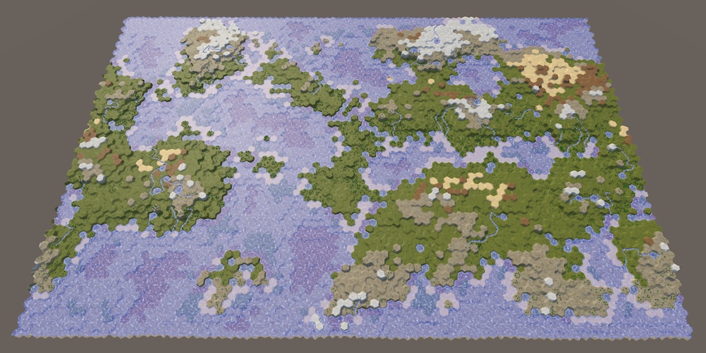
A tutorial series about the creation of hex maps in Unity.
In the shader graph, is there any way to determine whether certain vertices are being stretched farther than a certain amount? For instance, I'm trying to make a mask to subtract all stretching-textures from my material. Thanks.
I'm creating a voxel engine with the use of a greedy meshing algo. so im trying to detect when textures are being stretched. (And then later down the line multiply the tile-repetition by the stretch length)
Even if I manually triangulate in blender it makes no difference
Im trying to implement this now and I've hit a snag. They do:
then later
 1/dirToLight```
But this doesnt work because what if one of the 3 xyz values of the direction towards the light is a zero? Then you get a 1/0 situationHow do I resolve this?

The above is equivalent to 1/dirToLight, right?

plugging in a one doesnt do anything difference since its still possible the light direction could be a zero
what am I doing wrong? Where is my misunderstanding?
Also this is entirely an xy problem, I dont actually give a shit about any of that, Im REALLY trying to solve the implimentation of
float2 rayBoxDst(float3 boundsMin, float3 boundsMax, float3 rayOrigin, float3 invRaydir) {
but I dont know what I should plug into each of those values, so tracing it back to where it gets called leads me to needing to do that division by zero
I tried to impliment this function but I cant, I dont understand any of it and im getting nothing but bogus results

copied it in, but no matter what I give it as inputs, it doesnt work
giving up on this method now, I can't do it without help so its pointless for me to continue, its just hurting me to fail over and over and over
infact im in so much pain now im giving up on shaders entirely for the day
whoo fuckin hoo my entire accomplishments for the day ammount to about 15 minutes of being a worthless failure that achieves nothing
Is this what you need?


Hmm that looks about right, let me set it up on my end as well
Does unity still have problems with more than 4 textures on a terrain?
Yeah that is exactly what I was looking for.
How did you know do the Reciprocal thing? Is that what 1/view does?
It's the same as 1/In in the Default mode. The "Fast" mode uses hlsl's rcp function, which is an faster approximation, if you prefer to use that instead.
Oh okay, looking at it I dont see a difference between normal and fast so Ill go with fast
What ways could I make it not camera-centric? If I wanted it to be based on an arbitrary vector like light position?
changing in the light direction for camera position didnt work since its not the light position after all


maybe there is a way to get the light position here?
oh okay I can just feed it any old vector 3 🤔
neat

yo that looks sick
volumetric cube shader
Yeah I wasnt expecting that, you need to raymarch to get that result normally dont you?
Unsure what you are referring to exactly. But terrain shaders typically rendered in multiple passes (well, separate shaders connected via ShaderLab's "Dependency"), each rendering 4 layers.
e.g. for Built-in RP : https://github.com/TwoTailsGames/Unity-Built-in-Shaders/tree/master/DefaultResourcesExtra/TerrainShaders/Splats
For URP : https://github.com/Unity-Technologies/Graphics/tree/master/Packages/com.unity.render-pipelines.universal/Shaders/Terrain
If you're referring to Shader Graph, it doesn't have support for terrain yet and can only do one pass (so maximum of 4 layers)
heyy sorry to jump in the middle of this, but i'm having trouble with a shader thing in a 2D game, i'm extremely inexperienced with shader graphs, was following a tutorial on line and can't figure this out....
so i'm trying to create a haze distortion


Maybe this doesnt work the way I think it works, sending in a vector 3 position other than the camera's, it seems to make the input a vec3 from 0,0, -5, its the same thing.
I was expecting this to work as in the source direction towards the cube is that value, but instead it seems to be the value that represents the cube's center?
Maybe it behaves differently in scene, ill test it there

but applying it to the game object isn't working, its just remaining plain white
okay yeah changing it to a random vec3 and not camera makes it not work in scene
Ill keep playing with it to get the result im looking for, you've already got me unstuck so thats more than I could ask for already
Thanks for the push in the right direction Cyan 👍
Hi everyone. I bought an asset that was for built in renderer and I wanted to use it in HDRP. I see the shaders were built with Amplify shader editor. If I have Amplify shader editor can I use it to cnvert to HDRP?
doing these fixes now, I am unclear on some of the things you said.
view direction and main light direction were transformed from object to world space
in mine, they are world - > object, did you mean I should do it object -> world? As far as I can tell, its already the way you said it wasnt

Secondly, the way I defined view direction in my shader is different to in shader graph; mine was just negative of shader graph's (otherwise the anisotropy goes the wrong way)
What should I do to fix this? Does this need fixing? Looking at the end result, the effect is on the correct side of the mesh towards the light as far as I can tell. If I negated it, the effect would be on the wrong side?
multiplying EVERYTHING seems like it wouldnt do anything at the end wouldnt it? If every single value got doubled, nothing changed? Are you sure I dont have to only multiple a certain value somewhere?
is this the expected behaviour?


it burns out or gets broken very easily when I multiply everything
oh you meant the remap nodes, not the nodes they go into. Doubling everything into the remap nodes also breaks it

multing just the min and max seems to not break it, but im not sure if the result im getting is correct by doing that
This isnt working, all multiplying those vales does is no different than simply increasing min and max
which already wasnt working
As far as I can understand, im already doing the first two things you said Im not doing and are in error (the direction space, the view direction direction)
and what you said about doubling the values is no different than manually doubling them by playing with the values, which hasnt produced your result
im getting agitated and extremely frustrated again that this isnt working and none of the fixes are fixing it
In my mind I have to decide if either you are wrong, which is extremely unlikely, or if I am just too stupid to understand, and the only answer I can come up with is that Im just too fucking stupid to understand. its ALWAYS me, no one ever fucks up anything, its always me who's the collosal fuck up
time to leave again
multiplying just value doesnt work, multiplying just the output doesnt work, multiplying the min max doesnt work, multiplying all 3 doesnt work, multiplying all four doesnt work

you told me how to solve it and nothing I do following your instructions works
dude, its okay. idk what you're trying to accomplish in unity, but troubleshooting can be super frustrating, but you're trying, its okay if its not working, just take a break for a bit and come back with a fresh mind later. There's nothing wrong with you and theres nothing wrong with needing help from others
i know i'm not really part of this conversation but i saw your comment there and i can relate to how you're feeling right now
Thanks, I have mental health problems and a lot of self hate that make me struggle with failure, I appreciate the kind words. I try to bottle it up because I have literally no healthy way to express or release the feelings
i get it, i've been there. The important thing is that you don't give up
eventually you'll be able to do all this stuff without any help, but we all need help once in a while
and i guess, try not to think of it as failure. Its more of a learning process, and things not working is definitely part of the process. You've haven't failed if you're still trying
It's very unlikely irl that any component should be zero (but the shadergraph default is (0,0,1) so it goes pink). You need some sort of check to make sure it's never zero. Maybe instead of light direction, do abs(light direction + 0.0001) and then multiply afterwards by sign(light direction).
Right I think I got confused, sorry. (I think i switched both and then it worked, which, of course it should)
With the anisotropy, it gets brighter when you're looking at it from the sun side and darker when you look at it from behind, when it should be the other way around (to simulate light scattering mostly along the direction it's already travelling along)
Multiplying by the base color (potentially to some <1 power) would somewhat simulate light going through the skin of the cube (which is painted one color) and then passing through the interior (which has a potentially different color). If you want it to be more a dichroic effect you could multiply by (1-base color)^power (corresponding to light of the base color being reflected and other light being transmitted)
It's up to you
though I would also remove the subsurface color from the base color node; it should be emission only
You can just double the object space position in fact; at least on my side it works


tf did u just make a subsurface scattering shader
made it a while back, it doesn't render light rays or anything, just exponentials, anisotropy, and a little bit of geometry
it also only looks right for a cube which usually is not enough for SSS but my use case is a cube
Thanks Panzer, I will impliment these changes now
Is there a way to make a compute shader similar to a raymarch shader that only detects if an object is within 0 on the Z axis? I don't know if casting a ray can detect within an object
Basically i want to get an unlit cross section of my scene. I made a C# script to do this a long time ago but it's really slow since it only uses the CPU
Are you trying to say you want to "slice" your scene along the z axis?
You can't get unlit unless you do it in the individual object shaders, because after that fact they are lit somehow (and during). The individual shaders, though, could check their pixels to see range-to-z-axis (either world space or view space) and then update something I suppose.
Compute shaders don't de-compute lighting.
I guess a better way to describe it is to put the color of the shader onto the corresponding pixel of a rendertexture
Right. That would be done by the individual object shaders
Im pretty new to shaders, so i don't know exactly what HLSL/Compute Shaders can do compared to a C# script
In the GPU, you only retain the RESULT in a color buffer. You don't know what went into making that result (the original source color). You just have the result. You don't even know, after the fact, what mesh produced it. You have a color buffer and and a depth buffer, at min.
I guess I'm describing this wrong, im trying to make a game where you only see a 3D world by it's center cross section, and you can rotate the cross section along the Y axis.
I noticed when writing a script in C# that a raycast only works when it hits the outer "shell" of an object, so i would assume the same would happen with the shader equivalent?
Ah, that's volumetrics. But you can intersect a ray with a shell and intersect a shell with a plane.
Let's talk about "unlit" first.
You could have no lighting, just color. Is that what you want?
Since you have a 2D result, essentially.
Also, how do you view this "plane" that intersects your scene? From 3D space, so you can not move the camera and still see the plane rotate on the Y axis, showing different parts of the scene as it rotates?
There's also something called SDF (Signed distance field/functions) that allow easy volumetrics if your shapes are simple or computational.
Yeah i plan to just make the world out of cubes
Basically, the plane would rotate around the Y axis and the camera would orbit it as it rotates. I can make a small example if you want
Well, maybe needed, but not yet. Why I was asking was that if you could "just" cheat and put the near plane and far plane of the camera frustum to make a slice, and IF it moved with the camera, so the plane is always facing the camera, you could cheat.
But it would always look like a wall of cubes in front of the camera, sliced different ways...the camera view IS the plane as it rotates. But that's probably NOT what you want.
If i change the camera clipping to be a slice, it would just show the outer walls of the model and not fill in the middle.
Anyway, there is an intersection test between a cube and a plane, and if you know the color of the object and the cube bounding box (or if a perfect cube, not a rectangle you only need center and radius and maybe a rotation) you can intersect the two and basically color the plane where it intersects
But again, you'd do that as you draw all the scene objects. MAYBE you could set the near/far planes to avail yourself of early frustum clipping to avoid drawing things that don't intersect the plane, but the plane would either have to be frustum aligned (hence the "cheat") or you'd have to decide where the farthest point is on the plane that intersects the frustum
this is kinda what i want, first photo shows a slice of a blender monkey, second shows the plane that should determine what part is drawn, and third shows the original models without the boolean.


@regal stag IIRC has a page where he intersects meshes with planes.
The problem is that mesh boolean isnt reliable a lot of the time and isnt very fast
It's all computed in the frag shader.
Bump
Check your import settings that it isn't recalculating the UVs.
Also for debugging, output the UV values as a color and see if they are what you exepect to see in the red/green values.
Good idea. Do you have some tips on how I could achieve the second?
Are you in URP?
If so take the UV value and output it as base color in shader graph.
There's a UV node
If BiRP, just "return float4(uv.xy, 0, 1);"
I'm trying to make some fluid shader but after I apply to object it crashes, what is reason and how to fix it?


$50 USD if you can do it/ show me how to do it
Don't see anything particularly suspicious. Maybe there a division by 0 happening somewhere(in the step node?)🤔
Are you sure that the crash is caused by that shader?
I think this is probably a really simple problem, but I just cant seem to google the right words to find the solution
i have a few shader graphs that all have the same problem of only applying on one plane at a time, ie if I made a pixelation one, it only pixelates in one direction, one way
Not sure what you mean by that.🤔
ima send a screenshot
i broke it trying to fix it
uno momento
so here is the graph

and the result is these long strips

as opposed to pixels
you should set the default pixelize value to something other than 0 so you can actually see it in the graph
yeah i never figured out those default values
lemme try tho

so heres it again
but it makes like long pixel strips
the same problem is more obvious on my other one, the checkerboard pattern shader

on the xz plane its a checkerboard, but on xy its a stretched rectangle, the tutorials ive seen online just dont seem to have these types of problems
Your UVs are probably not set up correctly on those walls then
regardless of my personal struggle, how do i get the shader to apply on all faces, or is this a texturing/materialing problem
Need to use something like triplanar mapping.
Or actually UV the walls properly
Depends whether you want automated but blends when off-axis and is less configurable (Triplanar)
or hard coded but manually defined (UV mapping)
im glad you specified which option is which, because i had no idea lol
ill give both a shot after rigorous googling and see what turns out better
triplanar mapping worked pretty well I think, although the way I ended up getting it to work created a plaid coloring rather than a checkerboard
what you could do is lerp(color 1, color 2, remap((sign(fract(position) - 0.5).x*(sign(fract(position) - 0.5).y*(sign(fract(position) - 0.5).z), (-1, 1), (0, 1)))
which should make a checkerboard where every square is 0.5x0.5
(it should tile 3d space with cubes of alternating colors)
@regal stag quick and silly question, what going to happen to your BakeShader if we bake a material on an object with a non-unwrapped UVs ? as in the triplanar case if that make sense
It would need unwrapped UVs. Without them the result will probably be blank.
But you can still use triplanar in the shader. For example to bake that triplanar result onto the meshes UVs. So you can swap that part out for a single texture sample, rather than three.
(Though with multiple objects, that would now be different textures and there may be a cost to switching between them while rendering so you'd have to profile both and see. I know in Built-in that would mean separate materials, which would break batching. SRP batcher doesn't mind, but I imagine there's still a cost... If it's worth it, I guess using an atlas or texture array might get around it) 🤷
If you alter only the near clipping plane and leave the far one, you could maybe do Cull Off in the shader and use Is Front Face (or VFACE if surface shader), to render back faces differently than front ones (e.g. different colours). That could fake that "fill in the middle".
Or can use alpha clipping but you'd need to handle the intersection yourself. Kinda similar to a liquid shader. e.g.
https://www.patreon.com/posts/18245226
https://www.cyanilux.com/tutorials/liquid-shader-breakdown/
Though these are only on the Y axis. You'd probably need a Dot Product with the plane normal instead.
If the shader is lit, would likely also want to set the normals of the back faces to the intersection plane (so towards camera - I think that would be -UNITY_MATRIX_I_V._m03_m13_m23 iirc)
But if you need a far clipping plane too might need to look into other methods, like the sdf/volumetrics Carpe is mentioning.
Thanks for a detail and thorough explanation, 👍
I really think Unity should have this feature out-of-the-box really...
UE 5 has similar feature to this btw.. so it's nice to see it in Unity
does anyone know how to get specular lighting to work in hlsl and urp? I am using a method called UniversalFragmentBlinnPhong. Acording to the tutorial I was following you need to add "#define _SPECULAR_COLOR" but when I add it in my code nothing happens.
Hey guys, Quick shader graph question:
how can I create a property slider like the tree height one in urp shadergraph?
I know that I can set a float to Slider Mode to get a slider for a vector1/float. So I thought that the Tree Height slider would be set in a similar way?
What i want to achieve is the following: I have a smooth step and want to control its min and max values via a single slider
Is that possible?
My thought was that the tree height slider would be a nice visualisation: right handle is the max. left handle the min
You'd also need to set the specular and smoothness values in the SurfaceData struct (or UniversalFragmentBlinnPhong function params, depends which version you use)
I've got a template here which might help : https://github.com/Cyanilux/URP_ShaderCodeTemplates/blob/main/URP_SimpleLitTemplate.shader
There isn't an option that allows you to do this directly in shader graph.
Typically the way you'd probably handle this is by writing a MaterialPropertyDrawer (using EditorGUILayout.MinMaxSlider in this case) and adding an [attribute] to the shader code before the property. https://docs.unity3d.com/ScriptReference/MaterialPropertyDrawer.html
However, shader graph doesn't allow you to add custom attributes. You could use the "View Generated Code" button in the inspector on the shader graph asset, copy that code to your own .shader file and edit that. But then it's separate from the graph and if you need to make changes you'll need to convert & edit it again.
Or could write a whole Shader GUI, there is an option to set that in the Graph Settings. But might be a bit overkill imo. https://docs.unity3d.com/ScriptReference/ShaderGUI.html
Ive copied this node for node but my result is not the same as yours

Can you show me a screenshot of what yours looks like at values other than 2?
Or show me all your nodes expanded so I can see where the difference occurs visually?
Yeah I found an article that was foreshadowing that its not possible right now but they also posted a premade custom gui that seems to have minmax slider integrated.
https://github.com/needle-tools/shadergraph-markdown
It is a bit of an overkill tho to install and learn how all that works just to convert my vector2 into a slider. Similar issue if I convert the graph to code since I will probably still work on the shader in the future :/
So I guess I will just stick to a vector2 for now. SInce its a private project and not the main focus. Thank you very much for the explanation and the links. they maybe still become relevant in the future if I dive deeper into the shader rabbit hole, because then i really need a custom gui^^
So yeah. Thank you @regal stag 🙂
I have set both of the values and tried to change them. Nothing happens. My shader just seems to ignore that part for some reason
Hi, just sharing this here too in case you can help!
Unity Forum
terrainBlendBuffers = new ComputeBuffer(batchesT.Length, 16, ComputeBufferType.Constant);
terrainBlendBuffers[i].SetData(batchesT);
prop =...
I tried to move my code from structured buffers to constant buffers, no reason why it should work, but I failed because it seems the data is not correctly uploaded
anyone experienced this?
I am not convinced that multiplying the position is getting the same result as your shadertoy version.
When its a value higher than 2, it starts to produce very strange results:
The gif kinda explodes but you can see what I mean here

To me what I am seeing is not just that the cube is getting bigger/smaller, but its center point position is also changing
I tried a few different things but I was not able to stabilize/counteract the fact that multiplying the position causes it to change center point
here is my latest version based on your fixes/suggestions.
- view direction is negated now, that looks better and explains why my front surface kept burning out no matter what values I gave it
- Subsurface has a multiply value, but it doesnt quite do what I want it to do, it doesnt bring it closer to looking like your shadertoy version, it just makes it easier to adjust min and max at the same time.
- Maximum 1s before going into the SSS because it was blowing up pink and that stops it
it looks very clean at least

It should just be 2; the remaps make a depth parameter (which then goes into the exponentials) -0.2 on one side and 10 on the other; without multiplying by 2 the cube is half the size so it's 2.35 and 7.45 instead (which aren't the values we want)
This confuses me.
You said in your shadertoy, the size of the cube was 2, and in unity the size of the cube is 1
Why does the cube have to be exactly the size of 2? Why cant it be any size?
it makes sense that it should die if you go >2 as well, bc then you're exponentiating a large positive number and it dies
The unity cube has faces when a coordinate is plus minus 0.5, my shader graph has faces at plus minus 1. If you made a new cube mesh where in object space the faces were 0.333, you'd multiply by 3 to get the same result.
Hm so you are saying all the math depends on the cube being -1 to 1?
If you tune the min and max values going into the remap, you can make it end up the same, but it's assuming it's -1 to 1 and that gives it nice properties like going to white when max is around 0
Im still 100% convinced that you have it wrong, I'm not trying to argue but this should prove it:


the only difference between these two is that Position is multiplied by 2 in the top one
the light and orientation of the box are both 0 0 0
when its 2x position, there is a very clear bias to one side
but they are both aligned 0 0 0 so that should not be the case, right?
Could be how axisA and axisB change over the corners
I think the lack of bias in the bottom one is that the subsurface scattering depth in the face pointing straight at the main light is 1, whereas if you just go over the corner, it drops instantly to 0.5 (well, instantly for a sharp cube anyway). So the light transmitting through to other faces (which gives the bias) is muted compared to the symmetric 'is this part facing the main light' check
hm so you're saying its my mesh thats the cause 🤔 it does seem to work better on a pure cube


Indeed. You can still use the same approach, you just need to change how you calculate the subsurface depth
oh wait hold on

NOW its clear theres a problem
the only reason the problem wasnt showing in the above was because the light was dead on
if the light is any other direction but dead on, this happens
but that is with a multiple higher than 2
It'll do the same if the value is 2
The same?
It'll have the same swirly bias
oh
I was refering to not the swirl but the weirdness with the segmented color shapes

but maybe this is fine, it doesnt happen with a size above 2
this is probably as good as its going to get, I should be satisfied with this even though I feel like it doesnt match your shadertoy version 1:1
"perfection" is a bad goalpost to strive for because itll never be so


it looks very good and I wouldnt have got this far without your help
Oh right, that's from the way it removes large values (because exponentials grow pretty quickly). It does a hyperbolic tangent, which flattens the intensity out at 1, but it's fairly sharp. (the graph is tanh(exp(x)))

If you leave the scaling at 2 and take the value in the remaps from -0.2 up, it does the same thing
You can try changing how the subsurface depth is calculated so it works better with your rounded cube if you want
What would you suggest?
Maybe try saying the normal for subsurface (eg calculating axis a, axis b) (possibly excluding the face C part) is sign(position) * floor(position/max(position.r, position.g, position.b)) where position and normal are in object space, an position is position/max(position.r, position.g, position.b)
I will try that now, reading it I'm not clear on what that actually does, Im assuming it will somehow round the edges of the cube area?
like how an SDF cube can have rounded corners?
👀 right away the sine of the position is very interesting


where position and normal are in object space
Normal is not used in this as far as I can see 🤔
what are the three maxes the max of? because it doesnt seem like the max of all 3 is the answer

my multiply was too high, but its still definitely borked
sign(position) * floor(position/max(position.r, position.g, position.b))
max doesnt take 3 values, Im unclear on how to impliment that
still does it even without the 2x

normal vector isnt being used in there at all, did maybe you meant one of those positions should actually be the normal?
I gotta head out and get groceries but when I get back Ill keep plugging away at this
hey all. quick question. Is there some way in converting a shaderForge shader into a shaderGraph shader? and if yes, how?
Not automatically. You would need to recreate it
ah ok. it isnt mine but a package i bought a year ago. the creator said he will not update it. and i kinda need it.
then i guess im screwed, cus ive got limited knowledge of shaders.
Hi, how do I get the offset property to work? Im using the Dissolve shader that is included in the "Unity Particle Pack" asset https://assetstore.unity.com/packages/essentials/tutorial-projects/unity-particle-pack-127325. Currently when I change the offset property nothing happens! I guess I need to add it in the shader somewhere but im very new to shaders so I dont know where to add it.
Just max(a,max(b,c))
My thought was to generate what the normal vector would be, were it an actual cube
Thats what I thought so thats what I tried, but as you can see the result is wild
So I must be making a mistake somewhere
oh when you're doing the maximum, do the maximum of the absolute values rather than the values themselves
Ah okay trying that now
In all the other Position instances, should I be using the absolute there too?

the floor is causing it to pixelate severely
I think just when you're doing the maximum
Whats the purpose of the floor?

it seems to jank it up
Without the floor, plugging it in place of where Normal Vector is seems to work and look good
I'm trying to turn it from continuous to faces
Is there any way to get Texture2D pixels as Color32 values in a compute shader?
As in having them stored as a float4 of 0-255 instead of 0-1
myColor *= 255
I made a shader that just changes Hue/Saturation of an Image for UI.
I made the shader in shader graph.
I need the image to be masked. I found a roundabout way of getting the code from the master node and adding stenciling and ColorMask to that code.
When I do that the image can indeed be masked.
But the problem is I can no longer access the values on the shader/material. They just remain greyed out. Which I need to change hue/saturation.
If I remove the ColorMask[_ColorMask] portion I can continue to adjust the values but the image is no longer masked.
Any way around this?
I figured out a fix. I guess.
private void Update()
{
    thisImage.materialForRendering.SetFloat("_Hue", Mathf.PingPong(Time.time, 1));
}
Apparently you can just set values on the 'materialForRendering' opposed to just the material and it seems to work. Although it says materialForRendering is Get only... Interesting.
Material itself is read only, but it doesn't mean that it's properties are too.
https://github.com/TwoTailsGames/Unity-Built-in-Shaders/blob/master/DefaultResourcesExtra/Particle Standard Unlit.shader anyone knows how to alter the alpha channel in this shader?
This shader's fragment function is not actually defined in the shader, but in some other file. Gotta find and modify it or define a new function to put your code in.
yea i figured but what file is that?
In one of the includes obviously.🤷♂️
Could copy the name and search in all the included files. Or Google.
Hey, can anybody help me ? I'm trying to replicate a toon cloud system that looks like the clouds from "Sable" (see picture below)
No picture below
Should be pretty simple with some perlin noise and "step"
Well, you'll need to write a shader or use a shader graph. Both of the things I mentioned are nodes available in the shader graph.
yes i already used the shader graph for some of the effects in my game, so i already have it
what type of shader graph is it ? unlit shader graph, lit ,.. ?
Unlit should do
i added a result.a = 2 before the return but nothing
Added where? To the original file?
no i made a copy of both shader and cginc
but nothing seems to have changed
maybe result.a = 2 is wrong
im really at the dark here
i just want the whole thing to be more opaque
It should be a value between 0 and 1.


I misread your message as 0.2
it looks like its adding transparency on the effect itself rather than only around it
@kind juniper I'm at university rn, but can i dm you later to help me make the clouds ?
I'm not even sure that it's transparency. It looks like something else is overlaying the sprite..?
No DMs please. You can ask here.
ok, can i talk to you later then ?

i went the camera closer
you can see its still transparenty
You can ask here. If I'll be able to answer at that point, I will.
OK, thanks a lot :)
Ah, I see now. Assuming you're modifying the right function it could be applying the transparency in a different pass perhaps.🤔
There's also the matter of whether your shaders are even used and not the original ones(especially the included one).
is there another way to fix it?
Disable transparency on the texture.🤔
Take a screenshot of the texture import settings


its even worse with grayscale
Hmm
cause the smoke in on the greyscale so it makes it more transparent
maybe i need to output less transparency from embergen
Perhaps.
Not entirely sure, but there might be material setting responsible for that in the material.
Or directly on the particle system renderer module.
i searched tho didnt find something
increasing the flipbook resolution kind of helped
Hi! Help me please understand the shaders. I downloaded the models from mixamo and other sites, and for example mixamo models has 3 inbuilt textures, diffuse, normal map and specular. I see that diffuse placed in albedo cell, and dont understand why texture call diffuse but placed in albedo cell. Also normal map texture placed in normal map cell. And specular didn't use at all. Unity defined standard shader for model. Can somebody give a source to resource where i can read everything about textures and unity shaders, how different texture types using, how to use different shaders? Or maybe you can explain here?
Hey guys, is Unlit Graph and Unlit Shader Graph the same ?
For Unlit Shader Graph, I get a Vertex node instead of a Unlit Master node
@kind juniper i think i kinda did it
i set the hdr color of the maps to -10 and emission to 2
makes the smoke darker and the fire blooming
Sounds like you're comparing different versions of shader graph.
current tutorial I am following is using Unity 2019, whereas I am using unity 2021
I guess they are the same then?
does anyone how to learn lighting in hlsl shaders for urp? I have tried to find it but it quickly gets exponentially harder and its very very confusing to try and learn
Kinda. There's no master node in the latest versions.
got it
hey guys, can anyone tell me why my hdrp liquid shader is doing this? it renders stuff under it either blindingly bright in bright conditions or black in under-lit areas. how do i fix this?


Could maybe try the HD Scene Color node instead of the regular one. But I don't work in HDRP so not sure
looked the same until i checked the exposure checkbox which makes sense beacuse this is how the whole scene looks without exposure in the global volume. thanks alot dude!
Hello folks, I'm trying to acheive volumetric ambient lighting in URP for this art style I'm experimenting with.
I have made a shader that allows me to define a custom ambient light value, now I need to modift that value based on volumes and that's where I'm stuck.
How can I go about modifying a shader that is in a certain volume?
Can I read these volumes from within the shader? Perhaps the same way one can read additional lights via the "GetAdditionalLight" method?
Can I use URPs volumes or do I have to implement my own volumes?
I'm somewhat new to shaders and URP so I appologize for any terms that don't make sense.
I'm playing around with shadergraph but I'm a bit stuck.
I'm trying to change the color 'tint' of my image texture by position and also UV. So every tree will have a slightly different color.
Now I want to mix this with my image texuture. I tried several math nodes, like add, multiply but or it become to dark, or too light.
What would you guys do/suggest?

Perhaps a Lerp, with T set to 0.5.
Also is a little strange to use a 0-2 range to sample the gradient (top one). I'd keep the maximum at 1 and alter the gradient keys. Or could Saturate to clamp before sampling.
Could probably remove the Sample Gradients entirely if you just need to Lerp between two colours (light green and a darker one). Would be cheaper.
I will do some testing, thank you.
Anyone come in contact where the Unity Toon Shader repo from github wont import to a project?

i think the issue is that the main folder of the repo does not have the package.json so its not a valid package
the sub folder com.unity.toonshader looks more like it
https://github.com/Unity-Technologies/com.unity.toonshader/tree/development/v1/com.unity.toonshader
I tried your suggestions. I replaced the gradient with color nodes and used lerp between them.
The main idea is, every tree has a little different green tint based on position and every tree has different tints on their UV (brown inside / green outwards)
For some reason I'm stuck again. Did I use the lerp nodes incorrect?

Perhaps you want it more like this? Otherwise it won't really be brown, since that's being tinted green by the multiply.

There's not really one "correct" way to handle this. It just depends on what you want to achieve.
Maybe you also only want to take one axis of the UV? (So use Swizzle or Split). Depends on what the UVs look like.

Hello, I'm using a default texture, but when I see the preview in the Sample Texture 2D node it looks weird. It's supposed to show transparency there but instead makes these weird colors show. Other transparent objects act normally.

the white is meant to be transparency
I was wondering if the weird things shown in the first picture shows the actual pixel data perceived by shader graph or if it's just something I can safely ignore

around the border in particular, it shows some fuzziness. That's probably because the circle has a transparent edge
I'm not sure why it's so.. colourful. But shader graph previews do not show transparency, only the RGB data stored in the texture.
As long as the graph surface type is Transparent, you can connect the A output of the sample to the Alpha port of the master stack which would hide it.
weird my preview stopped showing
Also if the circle just needs to be black / solid colour, could just connect a Color node to the Base Color rather than the texture RGB.
Could also use a procedural method to produce a circle (e.g. Ellipse node) for the alpha rather than using a texture.
oh god
i forgot shader graph was the best
no more brush textures
does shader graph have a documentation?
I wanted to know how the ellipse's width and height values relate to the texture's
do they relate to _MainTex?
It does. https://docs.unity3d.com/Packages/com.unity.shadergraph@14.0/manual/index.html
Node Library lists the nodes. Can also right-click a node and there's an option to take you to the documentation page
o:
In this case width/height would be based on the UV coordinates
thank you very much for your help, cyan. It was very helpful

yeah, what is that UV i keep seeing?
sorry if I don't respond i have class
thank you once again
UVs determine how the texture is mapped to the 3D mesh. UV0 means it's using the uvs stored in the mesh. https://docs.unity3d.com/ScriptReference/Mesh-uv.html
Can look up some "uv mapping" or "uv unwrapping" tutorials for more info.
I followed a whole course about most nodes but I'm still confused if I need to work something out.
If I split the UV in to green channel to give the root of the pine-needles more brownish look, it only doesnt want to tint the image texture a lot.
Also could I control the position of the green channel a bit more?

An non alpha example of the face.
I think most of the color is from your sample texture
Then instead of the last lerp you probably want a Multiply and edit the texture to be greyscale (but quite bright - so it doesn't darken the colours too much)
For controlling the gradient better, could use an Inverse Lerp & Saturate on the G output. Or Smoothstep.
I will try that. Thanks for your time, much appreciated!
Code question 🤔
void Unity_Hue_Radians_float(float3 In, float Offset, out float3 Out)
{
    /*
    float4 K = float4(0.0, -1.0 / 3.0, 2.0 / 3.0, -1.0);
    float4 P = lerp(float4(In.bg, K.wz), float4(In.gb, K.xy), step(In.b, In.g));
    float4 Q = lerp(float4(P.xyw, In.r), float4(In.r, P.yzx), step(P.x, In.r));
    float D = Q.x - min(Q.w, Q.y);
    float E = 1e-10;

    float3 hsv = float3(abs(Q.z + (Q.w - Q.y)/(6.0 * D + E)), D / (Q.x + E), Q.x);

    */

    float3 hsv = In;

    float hue = hsv.x + Offset;
    hsv.x = (hue < 0)
            ? hue + 1
            : (hue > 1)
                ? hue - 1
                : hue;

    // HSV to RGB
    float4 K2 = float4(1.0, 2.0 / 3.0, 1.0 / 3.0, 3.0);
    float3 P2 = abs(frac(hsv.xxx + K2.xyz) * 6.0 - K2.www);
    Out = hsv.z * lerp(K2.xxx, saturate(P2 - K2.xxx), hsv.y);
}```

I want to re-write the Hue node to take in HSV instead of RGB, I thought it would be as simple as passing in HSV and ignoring all the RGB steps before it, but passing in the same HSV values (but in RGB space) in the real Hue node doesnt produce the same result.
How would I correct that?
I am not sure what K, P, Q, D, and E refer to to translate whatever changes to the RGB values occur
HSV was the absolute of a bunch of maths on the RGB transformed values KPQDE
but I have no idea what those are or how to get the same result but skip using RGB entirely

How to set up Hue Saturation Value, or HSV, Shader Graph nodes. Using Unity's Shader Graph to convert translate from RGB to HSV and back.
this guy explains a lot of how to make it, but I dont grasp what I have to do to skip RBG entirely and just do HSV and still get the same output

maybe the real problem is that my HSV values are NOT equivalent??

better example
bottom left color is the HSV values of that color
top is the same values in HSV
top is taking in HSV, bottom is taking in RGB and converting it to HSV
outputs not the same

hmm 0.75 and 0.25 seems to approximate what I would expect from 0.5 and 0.5
that seems weird???

I thought I had it, but it stopped working as soon as I changed the HSV values
there is clearly some kind of range rescale changing going on behind the scenes that im not privy to from the HSV values of a color
im guessing the HSV is not actually the values it says it is?????

the problem isnt gamma space
I dont have enough information to solve this
all im doing is groping blindly in the dark hoping to randomly happen upon the sollution
can someone more knowledgable than me tell me where im going wrong?
@tight phoenix I don't really know how the Hue node works. But if it's just a hue-offset and you're in HSV space, I imagine you'd just need to Add something to the first component (since the H in HSV stands for the hue) 🤔
Could then use a Colorspace Conversion node to go from HSV back to RGB (or Linear)
Perhaps that's the same as you have in the custom function though
My custom function right now is the Hue node's code from the doccumentation, but with the RGB to HSV section chopped out. (taking in HSV directly)
The first value is hue, hue being 0 is just Red
the S and V are the part that isnt making sense, 0.5 0.5 I would expect that to be half saturated and half light
but an actual Color that has 0, 0.5, 0.5 HSV doesnt produce the same results
my thought is some kind of gamma intereference is happening, or that the color's HSV values surfaced in the window are not the true HSV values, or some other third thing 🤔
These seem to be equivalent, (in linear color space at least)

I think you can't just use a Power node with 2.2 since that's for converting between RGB->Linear, not HSV
That does work to get the same color, but the problem I am trying to solve is sorta the opposite of this
I don't want to get the color, I want to remove RGB entirely, I guess what I want is to know what this conversion is doing to take RGB to HSV 🤔


The end result I want is to be able to type HSV values and get the same result as a color of those HSV values
Ill look at the doccumentation on the colorspace convert to see what its doing there

Im trying to just remove RGB to HSV from here and take in HSV directly
but when I pass in HSV values, they dont return the same as if I passed in RGB values of the same HSV
I want HSV to HSV??? but thats not a thing
there is clearly something wrong somewhere
the wrong is that the HSV im inputting isnt returning what I expect those HSV values should return

bottom - the HSV of that color red is 0, 0.5, 0.5 (according to the color rollout when you click on it)
but when converting that color red to HSV space, the ACTUAL HSV values are 0, 0.75, 0.25 🤔
so the HSV values on the color rollout are completely false
Yeah it seems a bit odd. If you use Linear->HSV they are (0, 0.5, 0.5) though. But I guess the Hue node is assuming RGB->HSV so that's where it goes wrong
my expectation is that HSV would work like this:
0 to 1 is red to red
0 to 1 is no saturation to full saturation
0 to 1 is from black to white
I'm glad I'm not crazy 🤔
I kinda hate colorspace conversion stuff, it always confuses me 😅
Yeah it's pretty cryptic
the entire X/Y problem of this entire affair is that I want to be able to pass in values to control how light/dark it is and how saturated/unsaturated it is
which should be HSV values 🤔
the hue node only takes a color though

@tight phoenix I think I might got it. Swap out the "HSV to RGB" part in your custom function for the "HSV to Linear" instead.
So,
float3 hsv = In;
float hue = hsv.x + Offset;
hsv.x = (hue < 0)
            ? hue + 1
            : (hue > 1)
                ? hue - 1
                : hue;

float4 K = float4(1.0, 2.0 / 3.0, 1.0 / 3.0, 3.0);
float3 P = abs(frac(hsv.xxx + K.xyz) * 6.0 - K.www);
float3 RGB = hsv.z * lerp(K.xxx, saturate(P - K.xxx), hsv.y);
float3 linearRGBLo = RGB / 12.92;
float3 linearRGBHi = pow(max(abs((RGB + 0.055) / 1.055), 1.192092896e-07), float3(2.4, 2.4, 2.4));
Out = float3(RGB <= 0.04045) ? linearRGBLo : linearRGBHi;

That looks right, trying that out now
Boom that solved it

the hue node outputs in RGB space but I needed it to output in linear space was the problem?
Guess so 🤷


What is an ndot?
I know what a dot product is, and a cross product
but I havent been able to find ndot on google
is it a normalized dot product?
How can I tell how far away from an edge I am in a shader graph?
I want to make a gradient from an edge that changes color
the Distance node might do that for you
something kind of like this, but it respects those sides too

I'm thinking the thing I want is fresnel, problem is I don't know how to make it look like how I expect it to
like, this looks correct
but it only looks decent on a sphere

Fresnel works the way it does because its a dot product between the sphere's normals and your viewing position
so I need something that maybe uses the object's UV?
if you want that kind of fall off on a flat surface, try using a Tiling + Offset -> Absolute -> Distance or Length node

