You could perhaps do something where you figure out where you are in the basis of the flake (create two random vectors A and B; then create a matrix (A, normalize(cross(A, B)), normalize(cross(A, cross(A, B)))), then multiply view direction by that matrix, yielding vector V) and then you can multiply V by some large number, floor, and add a half, to get vector Q, and check where that is relative to V (so rather than dot(view direction, random vector), do dot(V, Q))
#archived-shaders
1 messages · Page 6 of 1
it was brackeys 💀
but thx tho
it works now
how can i make it so u can see the hexagons better all aroudn the forcefield instead of j mainly at where it touches ground

cant see the hexagons at all on the side here^

How would I change my voronoi code so that the cell center is not the center but more like each cell is a ramp in an arbitrary direction? 🤔

can such a thing even be done?
I have random directions from that random node
x/y problem
im still working on this stupid POS

but every cell in my body is screaming that its wrong, its uncanny, its completely wrong wrong wrong, its no good
I cant figure out what I have to do to make it not shit
im physically revulsed by it
my graph just keeps getting bigger and bigger and messier and messier and I become more and more miserable because nothing I do works, it just looks like complete shit and I dont have reference for what looking good would look like, all I know is that its WRONG
its WRONG why caNT IT BE RIGHT
in crisis again time to go
Hey, I don't really know anything about shader graphs for unity, but I've got this graph im making from a youtube tutorial and the video is out of date, but seems to still be somewhat transferable, and im getting the magenta shade of death on my preview, but idk where the textures arent being detected, or what's going wrong here.

If anybody has ideas on how to help, I'd appreciate it
I can make it in Blender just fine, but idk how to make it in Unity. Trying to get a gradient into a transparency, and the closest thing I tried was this dithering texture video:


Learn how to create a dithering transparency effect similar to the one used in Super Mario Odyssey using Unity Shader Graph! This tutorial is also available in text format here: https://danielilett.com/2020-04-19-tut5-5-urp-dither-transparency/
💻 Get the source on GitHub:
https://github.com/daniel-ilett/dither-transparency-urp
✨ ...
Is it possible to reference a float from a monobehaviour to a script?
It's interesting, because I'm trying to do a similar effect, which I'm going to ask about. Great work by the way.
Thanks, happy to help in any way I can
I'll add more details, unless you know what could be happening right away, but my preview shows the sparkles, but my capsule model does not. I saved the asset.

It also does not show the sparkle effect in VR in Altspace.
I do have some properties, but I made sure they are set similarly to the one in the model.
Interestingly though, one of the properties in Shader Graph will only work if set to a value < 1. But for the model, it needs to be > 1.
I know this is all probably very vague without thorough explanation.
the whole graph, its pretty self explanatory.
random vectors into the voronoi, dot product view direction with them, variables to control the look


I followed a tutorial here: https://www.youtube.com/watch?v=jAOqmx764dA

Everyone loves glitter, but it gets everywhere. Luckily, we can just make a glitter shader instead. In this tutorial, learn how to use random noise colors (i.e. GIMP's Hurl filter) to make a glittery effect!
As a bonus, also learn how to flip the effect on its head to make a starry night shader!
✨ Based on a VERY GOOD UE4 tutorial b...
the only interesting thing im doing here is I am multiplying the round distance voronoi at the end so that the glitter is not solid chunks
Mine seems a bit different
Ah yeah I followed that one as well
not for the above, but when I was trying to do a glitter that one came up
I see
Maybe it has to do with my scene's lighting? I just don't know.
For instance, when I turn the camera around, the base color is extremely apparent

I'm no expert, but in my experience the preview and scene view rarely match up
You can try rightclicking on the preview of the final model and switching it to the capsule there

in case its the mesh that is the difference
Ah good idea hold on
Ah its dark on one side and light on the other?
Naw the capsule in the preview is fine

I just changed the ambient occlusion, which helped that nasty gray color
Did you check the material properties to be sure they're the same as these ones?

But still the problem is, it does not display the sparkles in the scene's preview, or in VR
when you make the material, if you make any changes to the graph, the material wont update
So if I make the glitter offset value the same as in the shader graph, this happens.

Thats weird
I wish I could help more but debugging is not my forte, you could maybe try deleting the material and remaking it, just in case
it can be fixed, but it will be a struggle (in my experience)
perseverence, and trying others tutorials, and posting in this channel
Alright. Yeah it's all part of learning, and hopefully I'll know what's going wrong if it happens again
Actually it makes sense that it would not show up in the scene, so I do have to start with it being pink like that and figure out what's wrong
Finally I got it. One property was the texture. It listed the default,, but when I actually went and browsed for it, and select it, it fixed it.
#archived-shaders message anyone
Arent monobehaviour and script the same? And how is this #archived-shaders related?
Oh sorry my bad, when I said script I meant the code for the shaders
Ah shader code, makes sense. You can use Material.GetFloat and Shader.PropertyToID to get the id. Direct reference isnt possible afaik
Ah, my bad, other way around, use SetFloat, direct reference is still not possible. You have to set every time the float changes
Magenta color means shader error, which most often suggests your current editor / render pipeline doesn't support Shader Graph
It could also mean no valid active target, but most likely you're trying to make an URP shader without URP configured
I think making them brighter and increasing the power couldn't hurt
Get a little bit of bloom on them so they look like they're flashing vs blinking on and off
You could take the dot product part, do acos, negate, multiply by your power float, exponentiate for brightness as well which should make it broader around the peak
Also you could try swapping to dot(reflect(view direction, random vector), sun direction), and multiply by saturate(dot(surface normal, sun direction))
And to make the sparkles more localised, in the reflect() you can swap random vector for normalize(lerp(random vector, normal, some float))
(btw every mention of view direction is normalized view direction)
Can you set base color to black?
What noise texture are you using and what noise scale value?
I have this grass shader, and I want a potentially endless list of objects(their positions) to push the grass away
Not sure how I could let the shader know what the positions are
I would fill a pre-allocated structuresbuffer
Not endless but can be large enough
Better than doing a 2 copies and redeclare to have it expand
@terse whale^^ that, if you can build it per-frame, so you have less to trod through each frame. Or if it is small enough to encompass the world, with changes.
But if not any of those, you could try screen-space depth buffer calcs. It would be rough though. I mean, you'd know there was something in the area, but you wouldn't know how DEEP it is. It could be 2 pixels wide from the view direction, but 100 units deep in world space. But if it occludes the grass, you may not notice much, since you'd only offset sideways.
I suppose you could do a sort of occlusion map as you draw everything, kind of like how they handle snow/mud indentations when things get drawn. So all your objects could draw into a world-space map as if viewed from above...a splat map more or less...and you could check world-space occlusion as you draw the grass LAST. That has complications too, like for things that have "legs" and aren't covering the whole ground where they sit...so you could also have a texture map of its "footprint" from above to draw into the worldspace map.
That map would have to be redrawn whenever things move, or completely drawn per frame.
It says Universal RP here and has the check mark, does that mean it's configured? Or is there more to set it up?

thank you ❤️
hi all, I am having this issue:
Maximum number (256) of shader global keywords exceeded, keyword VARIANT23 will be ignored. You will have to delete some shaders or make them use less keywords.
would this issue prevent shaders from working in the build? Because I have some shaders I did myself (in HDRP) that work in the editor but not in the build. Thanks a lot!
hey hi, im making a masking shader that renders everything inside the bounds of a collider.
Question is, how can i keep things once they are already rendered?
Ideally the character has this collider and as he moves the dark areas stay rendered.
Right now it renders everything in the collider but as he moves away it goes back to black oc. How can i save this information?
One common way is to use an orthographic camera, pointing down over the scene. Using a Render Texture target, that doesn't clear. Can render a sphere/particles/etc to it around the player.
Then sample that Render Texture in the shader and use it for masking - using world position XZ rather than model UVs, and with some remapping to get it synced up.
This kinda only works with flat scenes without any verticality though. It's the same sort of thing that is used to add interaction to water/grass shaders or trails to sand/snow.
Mmm i can see that, the target effect is for an autogenerated dungeon, so in the end what i'd want to do is have a collider per room, and render the room when the player walks in, mask out the rest that hasnt been visited already as well as surroundings.
(3D top down rooms)
I was considering making the approach you mentioned, predefining the room's bounds with colliders may have a cleaner final look for what i want.
Instead of having the character render around him.
Am a little confused when you say colliders as the shader doesn't know anything about the physics system. I guess you're sending positions into the shader via properties?
Yeah sorry, i use the collider bounds to calculate positions.
So i'd pass those to the shader
What does the background around these rooms look like? Couldn't you add a "ceiling" (with that same colour/texture) to each room which starts completely opaque but fades as a player enters the room?
i've tried this placing black walls. Ceiling isnt really a problem.
Thing is, these "rooms" are open spaces in my dungeons, like forest open spaces sticked together, so you can kinda guess what comes next room visually even with a ceiling.
Camera is per room, and has confiners, yet because of the perspective you still can see some of the others contents.
Usung black walls imitate the depth of the fotest, but looks a bit wanky tbh.
I was looking to create a more natural boundary for the rooms so i thought on playing with shaders that might give me more control for transitions (like disolving rooms or just making an actual gradual darkness/depth effect.)
it was also for the sake of learning shaders.
Something like this would be ideal.
The rooms look comepletely isolated by the dark.
https://youtu.be/4tyboMdYP1U
Hmm yeah, but in this case the rooms look completely separate. The whole screen goes black and transitions to the next room, likely teleporting the player in the process.
Yeah it looks like it.
Im gonna try the shader way and also padding room layout further from each other.
Then i'll make a decision on what looks best.
I appreciate your feedback 🫡
does anyone know if it's possible to force a shader to never support reflection probes/shadow casting/shadow receiving/etc?
basically doing this on a shader level instead of having to do this on a per-renderer basis

(basically it breaks batching when the shader doesn't even support these things, at least the reflection probes break it)
I wonder if the ForceNoShadowCasting subshader tag would work for the shadowCastingMode one? (And maybe receiveShadows too for Built-in RP)
https://docs.unity3d.com/Manual/SL-SubShaderTags.html
I'll try!
nope, same issue
im justngonna go cry in a corner then

working with invisible/ethereal renderers is, not super nice
really wish we could extend from Renderer
it's fine everything's fine

whats the best way to send an int array to a shader via c#, since there isnt a nice material.setintarray method?
are we supposed to just hack it together with a buffer?
or go even hackier still and send floats instead?
i realise that directx and opengl werent really meant to deal with ints until just a few years ago, but sending floats as indices is a little too rough around the edges for me
ComputeBuffer/GraphicsBuffer is the way, yes
Hi! I'm trying to use Unity's cartoon shader v2 from there:

Open Projects are small, open-source games where the community of creators is free to collaborate and contribute actively to the entire game development journey. In this first devlog, we're going to discover the ideas and the process behind the cartoon look we developed in the first Open Project, an action-adventure game titled "Chop Chop".
⭐ ...
I'm using URP. Everything in the editor works pretty well, but in the build shadows doesn't work for object that has this shader. Lit shaders cast shadows. How can I fix that?
Shadow mode is on on the renderer, I tested that on multiple objects, and settings is on ultra. Also urp settings is set to very high.
Is the graph defining _MAIN_LIGHT_SHADOWS keyword?

Shouldn't need to use it in the graph. It's used by the ShaderLibrary files.
Does the platform built-for support "Ultra"? (I'd assume desktop build would work, but if you're building for mobile....)
One way to check if it is using a fallback is to create a shader that fills everything with a single color other than hot-pink. Like, say, an orange color. And set that for the fallback shader even if you have to make a temp copy of the SG file output and do a search and replace for any fallback. IDK if there's an option to set the fallback directly or not.
I admit I'm guessing a bit.
Hi, is it at all possible to change colorspaces at runtime? It's very needed in my game
I'm working on desktop, windows, so yes
Default is ultra
Also cleared playerprefs, just in case quality had been different sometimes in the project
Well it's guessing something out of my understanding o.o
I don't know what you would try to get with that, check if quality is a problem?
I'd think that this works anyway
since normal lit shaders works
(in the build, too)
It won't be using a fallback for you desktop windows build, so nm.
Any other way to fix that? I'm really a noob with shaders and my guess is that this shader was not built for urp
but then, why would it work perfectly well in the editor?
IDK why it doesn't work....
You can try and post the shader and see if anyone can duplicate the problem.
It should be the same as in the tutorial

GitHub
Unity Open Project #1: Chop Chop. Contribute to UnityTechnologies/open-project-1 development by creating an account on GitHub.
The one I'm actually using is a bit modified, I merged it with a grass shader from brackey's. But both of them doesn't work, and I think that if I can make work the basic toon shader, I can make mine work
(I'm testing anyway with the basic toon shader, to be sure that I did nothing bad)
Have you tried the one in the main branch? It might be more up-to-date
Though I don't really see any reason why this one shouldn't work too.
This looked interesting, but IDK your use-case.
https://medium.com/@abdulla.aldandarawy/unity-always-be-linear-1a30db4765db
Medium
why and how to achieve linear rendering with unity’s gamma color space
I'll try... At this point I'm basically trying everything, touching every setting, changing anything
Doesn't work
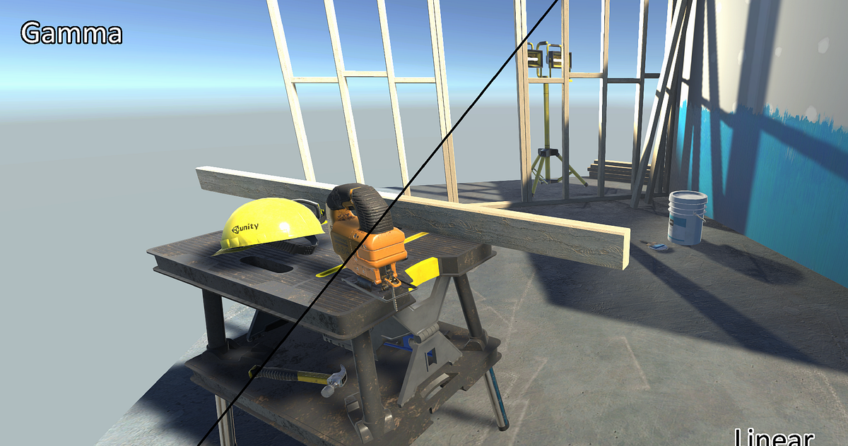
I'll check it out although I'm pretty sure I've tried some things like this, my main problem is blending of the colors I believe. In Linear vs in Gamma it looks diff. (I'm using 2d no lighting rn) so like alphas on top of eachother for example
looked at the wrong comment sry ahah
Actually yeah, no looking it over thats not what I want but is cool! Basically I have an old game we worked on that I want to convert the textures and art over to unity to look the exact same - for older users they can convert their old work over, but for newer users we want to use linear rendering. When using linear rendering with the old stuff and converting the gamma colors to linear to look the same the blending of some colors looks off. Which we need it to look the exact same. So we can do that by just using gamma color space but we'd like to use linear.
Very niche case ahah.
You're in a catch-22 situation.
Blending is different in different color spaces.
That's just the way it is. Mathematically.
You've seen the blending examples at the end if this, yes? https://docs.unity3d.com/Manual/LinearRendering-LinearOrGammaWorkflow.html

Yeah thats why I was hoping that I could change color spaces in runtime somehow. Cause for old levels - imported ones we could use gamma and then in newer levels created in the game we could use linear. Would fix all problems
Yup I've seen those examples
I think some stuff gets converted on import into the asset database. So it's a workflow thing, not a runtime thing. (well, really some of both I guess).
So unless you do it mathematically in the shaders...like that first article talks about, maybe with shader variants, IDK what to tell you. It's all in the math, and also in the final conversion that Unity/GPU will apply to the hardware. As you've read in those articles. I don't know of any magic bullet here. From what I'm reading, that is.
So maybe you could, in your shaders, have a function or something to covert back to gamma space to do your blending manually, and output an opaque result. A pain in the rear. Or maybe just the coversion back would be enough, IDK, since the back-buffer would be ?linear?
Yeah, from my understanding the most you can really affect blending is using different blend modes though, you cant make it completely custom as far as I know?
Sure you can. It's all math.
So you'd do the blending equation yourself.
But it's probably slower since you have to read the back buffer to know what you're blending on top of.
See the shader lab page for the blend command. That's all the math.
You can do that yourself and output an opaque result.
But yuck.
So I'd just turn Blend to Off and use the grabpass to do the blending myself I guess?
In BiRP you'd use grabpass, or some form of it (there's an option to do it similar to URP's grab-at-end-of-opaque by naming the grab texture and doing it at the right time).
In URP, you'd use the opaque texture grab, and do your special blending in the transparent materials/queue. URP doesn't use grabpass in shaders that I know of.
So for a traditional blend, you'd do something like
resultRGB = sourceColorRGB * opacity + backgroundColorRGB * (1-opacity).
I think that's it.
You could have those colors mathematically in any color space I'd suppose.
This is all spit-balling, so grain of salt.
Don't ask me how to convert between color spaces but I'd look for existing macros.
Hmm okay ill look into it, I tried to use the grab pass a bit before without blending and couldnt get it to blend right but I'll keep looking into it, thanks!
are you in BiRP?
Yup
Hello everyone, I'm new to shader programming and am using a stencil to see through walls that are obstructing the player like so: ```
Stencil
{
Ref 1
Comp Always
Pass Replace
}
The problem is I cannot see any of my image effects through this shader, is there something else I can add to make them show up?Yeah, there's a "named texture" option IIRC, that let's you grab and save a texture, like using a full-screen quad to grab the screen. MIGHT be better to use that if you have a lot of blending to do, similar to how URP does it. But if you need to, you could do an unnamed grabpass per object as it is shading. It's a 2-pass operation then...one to grab the background and the next to shade over it. It's more expensive that way, which is why URP switched to the newer method.
Ah okay ill look into it more, hopefully this could help thanks!
One is a shader graph shader that you create via the shader graph.
The other is a regular shader shader that you write with your own hands.
Hi, I can't find a solution anywhere... Anyone can help me? 😦
I fixed it, finally!
The solution was to remove all those keywords. I don't know why it works, but it does (I tried that because a normal lit shader graph worked, and it hadn't those keywords, so I tried removing them from my shaders and it worked)
Thats... odd. A normal Lit graph works because it already defines the keywords in it's generated code. Maybe defining them in the blackboard no longer works? 😕
Maybe, but defining them twice also shouldn't do anything
I'll try it out on Unity 2022 a bit later
I would like to add a very bright star-shaped highlight to this overtop of only the highest value dots 🤔 I have a highlight texture, but I can't seem to figure out a way to map it to the center point of voronoi cells


Im -still- trying to get this glitter to not be shit but 🤷♂️
its gotten a little better but its still not right, not good enough, not the look I want

panzer mentioned adding bloom to them which is more or less what im trying to do, ill try to follow those steps now
Try adding the surface normal to the sparkle normal and then use that for everything
(and normalize)
Probably better to use a texture for everything then, maybe put some billboard quads with that star texture and a shader with the sparkle normal


texture is way less flexible though 🤔
in code do you think it would be possible to map 2D UV coordinates into each cell, like imagine each cell has that UV drawn into it centered on the cell center?

Yes, though I think you'd need to write code for it
yeah unavoidable if I wanted this (with respecting cell boundaries)

    for( int j=-1; j<=1; j++ )
    for( int i=-1; i<=1; i++ )
    {
        int2 b = int2(i, j);
        //storeRand = voronoi_noise_randomVector(p+b, AngleOffset);
        //randRes =  voronoi_noise_randomVector(p+b, AngleOffset);
        //float2 r = float2(b) + storeRand-f;
        float2  r = float2(b) + voronoi_noise_randomVector(p+b, AngleOffset)-f;

        float d = dot(r,r);

        if( d < res.y )
        {
            res.y = d;
            mr = r;
            mb = b;
        }
    }
Distance = res.y;```this is the code that draws cell distance circles
if I wanted to map UV data in there, I know that it starts at 0 and increases/decreases linearly on the x/y
Out would be a vec2
Create, say, float2 RadiusInCell outside the loop, then in the if statement, set RadiusInCell= r;
Will do 👍
wow that was easy and worked perfecly

Nice!

Maybe also divide by ddxy of the out vector
Before the tiling and offset node
(should make it look flatter)
Flatter?
So the lens flares don't look stretched or squashed on the sides of the cube not facing directly towards you

ye
for some reason, nothing shows up

oh you're saying that it will correct this portion

to be still screenfacing?
it should roughly do that
Maybe in the tiling node, change the tiling to be something small?
Ahh that worked, 0.01
wonderful

:)
gunna check that 'every shadergraph node' video to see what DDXY even is
It's the sum of the screen space derivatives of whatever the input is, so ddx + ddy
precisely
I found a bug, with the DDXY the UV now scales in screenspace 🤔
zooming in and out affects the UV Tiling resolution
without it works as expected
you could multiply by the distance to the fragment
there are strange white lines around each cell 🤔 as far as I can tell they exist straight from the output

subtracted them out from the voronoi

not sure why they exist in the first place though
It's kinda related to mipmapping
oh the border of each cell its doing some kind of blend and that causes the UV coordinates to get weird there?
It relies on DDX and DDY to calculate the mipmap level for sampling. And since the UVs jump, it's trying to sample a quite blurred mipmap along those pixels
Could fix it by disabling mipmaps for that texture or using a Sample Texture 2D LOD node.
(Or whatever the equivalent of tex2Dgrad is (SAMPLE_TEXTURE2D_GRAD()?), which would allow you to specify the ddx/ddy values, which you could get straight from the regular UV)
Oh yeah you are right, disabling mipmaps for it removed it

Feels like we're getting somewhere 👀
I fractured a mesh in blender and need the pieces to break off individually, not all at once. The seams are noticeable when rendered in unity. Any tricks on how to hide them? Not worried about the normals, just the white speckles

If all else fails, you could use an un-fractured mesh and switch it out when it breaks
I imagine the speckles are being caused by the normals.
Can maybe use a Data Transfer modifier to transfer the normals from a non-fractured version of the mesh. Not sure how that'll look for the interior faces though.
I wondered if the speckles are the normals of the interior mesh faces peeking through, but then how are they receiving light?
This would work for the smaller asteroids because they will explode at all once, but the large ones come apart piece by piece
Could use multiple meshes for each stage of fracture
If the MeshRenderer is casting shadows then not sure. I guess bias settings might be affecting it.
Could try setting it to "Two Sided" shadows and see if that helps.
Maybe mesh deformation c# script would be the best choise but i dont really know how id do that exactly
better ish, I rotated the star UVs to be more randomized, and make them spin as well

but I'm starting to have doubts 🤔 feels like its moving away from good back towards bad/uncanny
every setup I do its incredibly difficult to control the ammount, intensity, density of the glit

easier to see the rotation and random rotation offset
The dots and sparkles might be a bit big. The sparkles especially keep getting cut off by the voronoi which isn't looking that great.
yeah I was wondering if I could edit the voronoi code to not be cells
to fix the cut off
I dont think its possible to do that though
have you added bloom?
Not yet per your way above post
Yeah, Bloom (and other post processing) can really help make stuff look good
I dont know why but I feel adverse to postprocessing, it feels like trying to fix a nail with a sledgehammer. Bloom might have tons of other affects on stuff in the scene so I dont want to add it just to fix this one thing
Unless other stuff has areas where the color goes >1 (in which case saturate the result), it should be ifne
if I use a different size cell for the glitter I can remove most of the cut-off, before I was trying to use the same cell size for the glitter and the other glitter

its the weekend, im going to have lunch and keep thinking on it 🤔
I have some resin glitter dice ive been studying carefully trying to figure out what it has and mine does not, iunno if its helping though
Heya, was wondering how i could use shaders to create something akin to this (in this case just used a perspective camera with 45 degrees angled quad) but with an orthographic camera?

find a tile-able grid texture, map it to a material, apply it to a quad
problem with that is it's an orthographic camera, hoped the shader would be the workaround to it
this is working pretty well.
I also introduced perlin noise to the cell density so that the sparkles are less uniform in size

🤔 I think I might finally be satisfied with that
the bright spike highlights were what was missing making it uncanny

without the spec highlight blocking it
Can you elaborate on this? I have no clue about the set up you want to use. Why it doesnt work currently?
If I am not mistaken, each vertical line would be when x/y={an integer multiple of some value plus an offset}, and each horizontal line is when y=arctan(1/{some integer}), idk where the offset goes tjere
i want to use an orthographic camera as my game was made with it in mind, orthographic camera's do not see depth unless it's a shader emulating so i was wondering how i could make a shader similar to it
sry this is for you @slender sonnet
wouldn't this go back to the same issue of not working with different sprites, or am i misunderstanding something?
is there a way, to place nodes on shadergraph from code?
say I have a shader graph
and i want to add a multiply node
but I want to add it from a c# script and not use the UI
is there a way to do that?
I assume still as an editor thing and not during runtime?
yes, exactly
I have a package which adds some Register/Get Variable functionality to SG
https://github.com/Cyanilux/ShaderGraphVariables
More importantly in it's "Extra Features" I also added keybindings for quickly placing nodes at the mouse position. By default bound to the alpha number keys.
Could see how I handled that in ExtraFeatures.cs (also first part of SGVariables.cs, to actually allow the editor to run the code) and maybe adapt that if required.
very nice, i will have a look
thank you
Idk what you want that pattern on, but what I said should give you the horizontal and vertical lines you want
Is it posable it add ignore Tag to shader graph shader?
shadergraph question 🤔 half my nodes turned grey, the nodes themselves not the output. Anyone know why?

did I hit some kind of hotkey or toggle some option?
trying to google it all I get results for is the shader itself doing stuff involving grey and transparent
Where is that chain connected to? It usually means the master port is not used by the current Graph Settings / Target.
Ahh you are right, I forgot I set it from lit to unlit

and was using emission before 👀
You can't edit subshader/pass tags in Shader Graph
Yeah for unlit would Add it to the Base Color result
A question regarding this - Ive been told that arccosine is slow to do and best to be avoided, so I went experimenting and found that saturate > power > mult produces 99% identical results to arcc > negate multiply > exponent 🤔
What does arcosine actually do, is this equivalent or am I missing something?

to the best of my eyeballs, the results are the same (first turn is arcosine, second is power mult)

Cyan, question about mipmaps and this look. What should I do if there's no texture involved at all? In the above I am using Distance node on the UVs to get circles from the voronoi, there's never a texture sampled at any step of the way 🤔

I can remove it by force but it looks kinda bad, and it stops working at steep angles


the only place I can see that might be the cause is the custom node voronoi has a bug written in it by me?
You're using DDXY, so that'll be why it's causing the lines
Eh idk, my knowledge on DDXY is quite limited
Fair, same here. Panzer was the one who suggested it to me
Should just be able to use the UV_Cells directly into the UV on the Tiling And Offset?
Or use the Spherical output on the Voronoi I guess
Looking at that now. The purpose of the DDXY is that at a steep angle the sparkles are still spherical instead of getting thinner

Hmm I see
I wonder if I could get the same effect by somehow using a fresnel to stretch the circle 🤔 Ill experiment with that now
Is this in HRP I'm using URP and don't see it in the graph editor, even googled pass tags.
What are you trying to do?
I followed this tutorial on how to add decals
https://youtu.be/f7iO9ernEmM
and I only want decals to show on the environment not the player, or enemies.
_ _

Decals have been available natively in HDRP for a while now, but not URP. Luckily, there are ways to add our own. In this tutorial, learn how to use some neat tricks involving space transformations and the depth buffer to make decals of our own which project a texture onto flat or curved surfaces!
✨ Based on NiloCat's fantastic impl...
The shape of the peak would be slightly different
But otherwise functionally the same
I think if you divide by dot(normal, view direction) it could do the same?
trying that now, my most recent attempt is almost there just backwards https://cdn.discordapp.com/attachments/996979168304697384/1011003452589088898/lolweird.gif

Draw the decals before the player/enemies. Use layers or a separate camera if you must. (EDIT) Put players/enemies in a higher render queue number than the decal render queue number.
In the UV
Cell UV
not the UV UV
Well I don't think the IgnoreProjector tag would help here as that tag only works in the Built-in RP afaik.
One way to make it not appear on players/enemies would be to use Stencils.
Shader Graph doesn't really have stencil support, but can still use two RenderObjects features on the Universal Renderer asset, instead of rendering those layers normally.
- Put player/enemies on "Player" and/or "Enemies" layers. Put decals on "Decals" layer.
- Remove those layers from the Opaque Layer Mask at the top of the Universal Renderer asset.
- Add RenderObjects feature, Event : Before Rendering Opaques (probably), Filter to Layers : Players/Enemies. Use the Overrides to add Stencil, Value : 1, Comparison : Always, Pass : Replace.
- Add another RenderObjects feature, Event : After Rendering Opaques, Filter to Layers : Decals. Use the Overrides to add Stencil, Value : 1, Comparison : NotEqual, Pass : Keep, Fail : Keep.
(Or as Carpe mentioned above, could use a separate camera to render the players/enemies ontop. Though I think that may be a little bit more expensive)
ive definitely made a mistake 🤔

(length(cell UV) is the usual voronoi output)
somehow I made cubes, and also its still backwards

The axis would be cross(view direction, cross(normal, view direction)) in 3D space
the top node there is view direction the name is just out of frame
I think the ddxy method would be most reliable tbh
It creates pixel lines that I cant eliminate
Could you set it to just repaint black everything that's near the boundary of two cells?

Doing this stopped working the steeper the angle got

Fair
There's definitely a geometric way of doing it
But you also need a way to get the 3D vector directions the UV g and UV r change along


I have the cross cross product, and the UV R and G
incidentally do cross products care which node is top bottom 🤔
Yes, but only a sign difference
length mult one minus gets me the circles

saturate at the end bc we don't like negative colors

you need to figure out the UV g and UV r directions in 3D space
It changes for each face though
oh
my thing is a cube so I can just use world position for that I think?
object rather?

That doesn't tell us about UVs though
I know what UVs are
Im saying any two vectors can be UVs
I can map textures onto that cube just from its object position values
this is starting to involve so much high level math just to make the steep angles shine in a way that probably no one will ever notice but us, it probably would be better to just not do this :C
If you do 3D voronoi but otherwise all the same things, the CellUV would be a 3D vector and then if you do normalize(reflect(CellUV, surface normal)+CellUV) you would get a vector parallel to the surface in the direction of the minimum
I do have 3d voronoi 🤔
You'd need to edit it to get the CellUV
It's the same as for 2D voronoi though, but with float3s instead of float2s
And then finally once you have the cellUV parallel to the surface (let's call it P), you can then get some 2D coordinates again but now flat to screen space by taking r=dot(P, normalize(cross(surface normal, view direction*))), g=dot(P, normalize(cross(cross(surface normal, view direction*), view direction*)))
*Could also use camera forward
How do you know all these formulas off of the top of your head? 👀
And then treat those 2D coordinates like you did before, with length(float2(r,g)) as your voronoi value
in no universe do I see myself being able to be like 'yeah just do (massive formula)' to get some extremely obscure vector angle
I don't, I'm partly guessing, but the rule is dot(a, b) gives the length of vector a in the b direction (if b is normalized), and cross(a,b) gives a vector perpendicular to both a and b
Ahh I see
dots and crosses, vector math
Indeed
Also since we're dealing with lengths we don't care about signs which is very nice
forgot to say to multiply one of them (r) by dot(view direction*, surface normal)
okay final_final_glitter_v2_final, no more messing with it.
I decided to forgo all that complex maths and just add fresnel to the sparkles to make it seem more dense at low angles

and no complex operations involved, a single dot product and the voronoi itself, the rest is all just mutiplication mostly
https://imgur.com/a/Igiri3D
Nodes for whomstever wants it
Not sure if this is what you meant but it works

will rendering after transparents come back to haunt me?
Depends. I believe anything on that IgnoreDecals layer also won't appear in the depth texture and opaque texture now. (But maybe that's the same even in the Before/After Opaques event, I'm not sure off the top of my head)
Hey everyone, just following up to this. I have a cutout with a stencil working properly as shown in the image, but I cannot figure out how to get my outline image effect to work inside it as well?

why isn't it working like this?

Decals are Transparent, so won't appear if you are filtering for Opaque
But the shader also requires the depth texture, so you'd need to make sure you are rendering after that has been generated. That's mainly why I suggested the stencil approach
What pipeline is this in? And how are the outlines handled?
Built-in, and the outlines are handled via an image effect I got off the asset store. I think this is the relevant shader code:

Right okay. I would assume it's also generating the depth texture in C# using Camera.depthTextureMode = DepthTextureMode.Depth?
Yes exactly
That should be using the ShadowCaster pass. So if you add the cutout to that pass too it should work.
Though it would also affect shadows which may not be ideal. Maybe there's a macro that can help there...
It might be #ifdef SHADOWS_DEPTH 🤔 (but apparently that's also for directional lights and spotlights... so probably won't help)
Sorry, still a little new to shaders. So I've added these tags to both the Outline shader: Tags { "LightMode" = "ShadowCaster" } and the cutout shader: Tags { "Queue" = "Geometry-1" "LightMode" = "ShadowCaster"} however now the cutout isn't working anymore, did I use it right?
You don't need it in the outline shader, only the cutout one. But not to the main pass, it should be a second separate one.
Is it a vert/frag shader or a surface shader?
The cutout is a vert/frag shader:

Ohh, it's using Stencils too. So wait, is this a quad rendering a circle texture?
And then shaders in the scene are testing against this stencil?
It's a sphere, but yeah, I've attached it to the player prefab and raycast to check if something is blocking the player
like this
https://youtu.be/-NB2TR8IjE8
And would this be compatible with shader graph or would i half to convert everything to .shader

Tutorial going over the core concepts and syntax for using the stencil buffer in Unity shaders.
Here is the full reference: https://docs.unity3d.com/Manual/SL-Stencil.html
Yes, shaders in the scene use this stencil:
            Ref 1
            Comp NotEqual
            Pass Keep
}```Right okay. So the "shaders in the scene" are surface shaders?
Yes they are
The RenderObjects feature has "overrides" for Stencil values, which would allow you to implement it without needing to convert it to a .shader
I don't know what the RenderObject or "overides" is but I'm guessing it has something to do with this.
These are RenderObject features. I've highlighted where the stencil overrides are.
That link might help, though they use the Depth overrides in that example.

If you add addshadow to the end of the #pragma surface surf lightModel line, I'm hoping that might use the same Stencil operations for the ShadowCaster pass...
@regal stag You're a hero! It worked like a charm. For anyone that might stumble upon this I added this to my surface shader: #pragma surface surfObject DustyroomStylized vertex:vertObject fullforwardshadows addshadow and this to my cutout shader: Pass { Tags { "LightMode" = "ShadowCaster" } }
The cutout shader probably doesn't even need the Shadowcaster pass. I was just confused about the implementation. Just using addshadow in the surface shader should be enough.
Hmm, taking that shadow caster pass away doesn't seem to work.
Hmm odd. I guess keep it then! 🤷
Nope didn't work

Can try the settings I mentioned in the original answer : #archived-shaders message
If that still doesn't work, then IDK though.
fair
Yeah I figured it was a good compromise because I want to have a lot of objects in the scene with this shader on it
guys i am reltively new to this, i wanted to ask smthn. i saw on the internet, that unity provides a premade Toonshader, but i am not able to use it i dont know why. has anyone here used it before?
i cant download it. its called toonshader 0.6.1
unity toon shader *
Not sure if you're still around, but I'm having weird issues with this solution. You can see that only at some angles does the outline effect come through
Why is my lerp result not red to transparency but rather red -> white -> transparent. It should be red to transparent

What does the alpha channel look like
presumably it's a gradient from white to black
No, it's white to transparent
Ah?
Ok so how could I get a proper red to transparent by mixing those two then?
Blend node give me the same result. I don't understand why.
I think you might be confused as to what transparency is.
Everything's just numbers. The RGB channels and A for alpha.
If you want Red to Transparent what you want is RGB: 1, 0, 0 and A: 1 -> 0
So you'd create a RGBA vector out of your color node and the alpha channel from your texture
But doing that, I lose the details from the texture.
For the sake if learning, I used a simple white to transparency texture, but in the future, I'd like to use this shader to create clothing and stack layers of textures (not decals, full texture wrapping all around the cloth)
It's basically like the lit layered, except it would handle transparency properly
As for what I mean by the lit layered not working properly, I opened both a ticket and a post on the forum but no reply so far
Unity Forum
Hi,
I'm trying to use the HDRP/Lit Layered to merge textures together.
Here is my first case, merging two gradient to transparent together:
h.png and...
I'm a little confused why you expect anything but what you have though.
You're blending between pure red, and that white and black, using a gradient. Why would the outcome suddenly not have white in it?
Because the alpha of the texture should feed the lerp. Meaning you get full red from the A which get applied on the pixels of the texture which is basically full white with a horizontal alpha decrementing
Even if you consider the black part of the texture which is fully transparent
Those two parts should merge properly, shouldn't they ? I mean, it red + white, why doesn't it result in red?

So obviously my understanding of lerp is wrong here but I don't know how to get what I want
Lerp is a linear blend using a 0->1 value as input.
If the alpha texture is a gradient (not what is shown in that preview) then there's a 50% blend between red and white at some point in the middle, getting pink, and then further down it seems to be a 100% blend to white, and then black
put a preview node between the alpha and the lerp
to show what that looks like
the alpha being used as T here is quite weird


yeah, it's as I say, a 0->1 blend between red and white at the top there
I'm using this PNG I created in GIMP
ok so yeah that makes sense. Anywhere in the image where the alpha is high it will trend towards being red. Anywhere the alpha is low will trend towards the texture itself
Ok I get it now, the alpha plays a role the blending of the lerp color, I thought it would only affect the alpha channel, not the color channel, that's my mistake
What you see is 0 as black (0, 0, 0), and 1 as white (1, 1, 1).
Lerp blends between A and B based on T.
When T is 0, you get A, and when T is 1 you get B
Got it, but what if I don't want the alpha to play a role in the calculation of the pixel color then?
what do you actually want?
Then don't use it as the blend factor of the lerp?
This

so you want multiply, no?
or Blend
oh - or just using a constant 0.5 as T in lerp
It's unclear what you want because you can get what you want via various ways, and we're just making assumptions
I don't know the name of the operation lol, I want my white -> transparent png to become red->transparent
sounds like multiply to me.
Ignore the whole "white to transparent" concept. Re-think what you have in terms of the color channels
Oh nevermind
If I don't plug the opacity alpha, then I do get what I want
That's the step I was missing

Now it's working like I expect. I just need to replug the opacity later
Thanks a lot for your patience and explanation lol
Must be annoying to explain beginners with their flawed understanding. Thanks again 😉
You've really got to break it down in terms of mathematical operations, because multiply is literally multiplication.
// Red: 1, 0, 0
// White: 1, 1, 1
// Black: 0, 0, 0
// At the top:
R: 1 * 1 = 1
G: 0 * 1 = 0
B: 0 * 1 = 0
// At the bottom:
R: 1 * 0 = 0
G: 0 * 0 = 0
B: 0 * 0 = 0
Once you start thinking in numbers or at the very least thinking as channels and not as an overall "transparent color" framing it starts to make sense
I do get the operation, the problem was the formula
I didn't know the 3rd input, opacity, affected the basic multiplication.
Like you explained, the lower the alpha was, the lower the 3rd factor in the multiplication was
So actually, it's not A.r * B.r
It's A.r * B.r * C.a
That is my mistake
I thought the C.a was simply added to the color result from A.r * B.r, which is huge difference 😉
Now it's crystal clear. Thanks again 😉
I'm afraid I'll have to bother you again, but how do I put back the alpha once I merged my colors?
I tried a multiply but still no alpha. Which node should I use to inject alpha in a texture?

Split and Combine
Annoyingly shader graph isn't very economical with the nodes. Ideally combine would be more flexible, but it's very verbose instead.
I must have mixed up the inputs

Strangely, the alpha doesn't get added in the combine?
I know I could plug the alpha from my gradient directly to the final alpha but I want to merge the combine with another texture layer to stack them 😉
you need to move the alpha from the texture straight to the alpha directly in the output
if you put the RGBA(4) into alpha it will use the first channel (red channel) as the alpha
Ah ok, I thought it was smart enough to get the alpha lol
no
Thanks for explaining
another option is to put another Split node in there
to pull teh alpha out
from the combine output
I must have missed something because the combine preview still has no alpha?

So even the split does nothing
I did miss something... Forgot to set the material as transparent, my bad :x
Ok, now another possible stupid question. How to reproduce the lit layered shader capabilities to handle smoothness differently between layers?
From what I see in shader graph, we only have one smoothness input.
Ah sorry about not elaborating on split and combine earlier. Shadergraph is icky when it comes to them as you just experienced. It really should be better at hooking that stuff up imo, there's rarely a circumstance where the first thing you hook up is what you would want
You need to blend the smoothness in a similar way you would the color. Depending on the intended output you might want to multiply the alpha by the smoothness to mask it, and then use max to combine those together. I'm not sure as to the actual correct blending for smoothness though, that may not work perfectly as intended. It's a similar logic to lerping things together with the alpha channel or using the blend node
Ok, so only use alpha channels to merge smoothness together then, that makes things easier already. Thanks! I'm not looking for AAA quality so even if it's a bit buggy, I won't mind.
Shader not rendering on the object ;-; what can I do


even tho it shows the preview on the shader graph
Is your material set to transparent on the gameobject too?
If you changed in the shader graph after, it won't update automatically on the gameobject
I had the material and the shader graph set to opaque, tried transparent too but both dont seem to do anything
There's just one thing I don't get about blending the alpha together, it's that with this method, the smoothness is still handled with only one unique variable. But the lit layered handles different smoothness for each mask. So this is a bit confusing at the moment.
you blend those different smoothnesses together using the alpha
or using the masks you use for blending, whatever that is
Ok, I think I get the picture after thinking carefully. I'll give it a proper shot now, thanks!
The max number of sample texture we can add in a shader graph is 16, is that correct ?
when i run my game in the editor, I see all the textures but when I build it, some of the textures don't appear. I see the purple "no texture" texture instead. How do i fix this?
You mean sample texture nodes or texture properties?
Nodes
But isn't it linked anyway?
You can't use 2 different textures on the same nodes anyway, right?
Theres no any limit of how many times you can use the sample texture node, maybe this makes it clearer https://forum.unity.com/threads/texture-samplers-limit-per-pass.605395/, limit of 16 is about different samplers, not sample texture nodes
OK, I'm confused about the meaning of sampler then. I thought it was a sample texture node but it's definitely not then.
I'll check some more doc, thanks
You dont need to worry about it, you will most definitely not hit the limit of 16
Well, the thing is I'm aiming to create a shader to stack texture togethers, it would work by the same amount amount of diffuse, normalmap, emissive and heightmap. meaning each layer needs 4 textures. You're saying I can put as many layers as I want like this?
Because the hdrp/lit layered is limited to 4 layers
I though it was because of the sampler limit but it's not?
What is the RGB value of a pixel in a normal map if we don't want this pixel to move?
0,0,1?
Ok, thanks Google 😄 1, 0.5, 0.5, 0.5 😉
Unity Forum
I'm creating a normal map from a render texture and GL drawing. It seems to work, but the areas that are not supposed to be affected by the normal map...
Seems 0.5, 0.5, 1.0, 1.0 also works? It's confusing...
Im having hard times trying to figure out what you are trying
Could you use Texture 2D Array instead?
I do not know how texture 2d array work
There. I have only 1 material for this tank top

I want to stack texture on it
here is layer 1

Er.. Main layer i mean
Layer 1

With layer 2

and layer 3

This way, I just need to change the layers to create whatever I want from the same model with only 1 material. I can also change the smoothness or metallic value of each part individually
There, jsut by changing colors, smoothness and metallic, I get a totally different feeling for the same model

It's awesome!
Different textures, each layers is again fully customizable

Im bit confused by the way shader graph handles samplers. Have you tried making much enough texture properties and connect them some way to see if you hit some limit?
Well, I've been able to merge my diffuse so far.
Now I'm stuck with the normal maps layers, since each layer has its own normal map AND like the lit layered, I want the main layer to be able to influence the other layers normal maps
I have the general idea but I'm just stuck with the strength parameter of each normal map which should be a number going above 1. But lerp and multiply nodes only use 0-1 inputs and I can't figure out how to increase the strength of my normal maps as I don't see any input in my shader
Nothing about the normal map input there. I remember in the default RP, there was a field which allowed me to increase or decrease the power of the normal map, but nothing here

It's confusing again lol
And as to why I don't use lit layered if it's already working, it's because of this bug :
Unity Forum
Hi,
I'm trying to use the HDRP/Lit Layered to merge textures together.
Here is my first case, merging two gradient to transparent together:
h.png and...
Which forces me to create my own shader but I'm a beginner so it's really slow and confusing 😢
Ok, found out there is a normal map strength node now which is what I was missing, nice 😄
I meant you could just quickly connect enough textures (like multiply all the textures together for example) to see if its possible to have that many textures, you can figure out the logic later if its even possible to have that many textures with shader graph
Ah, I see. Well, it should be ok for the limit anyway. The more the better but as long as I can get the same 4 minimum layers as lit layered, that should be enough for my ideas. (But more would be better because I also want to use this shader for the skin and apply several layers on the face, such as different layers of make up, face which already has the face texture + the eyebrows texture so only 2 layers left in lit layered lol. Yeah, my ideas are a bit strange but as long as it works ;))
If thats not possible, it may be that the layered lit is actually just custom editor which connects the textures into texture 2d arrays under the hood, that would decrease the amount of samplers (but also would ignore the wrap mode etc. per individual textures)
Maybe some other trick would be possible too
I can affirm you that the layered lit doesn't do this, each texture has it's own texture property
But, the samplers are shared between textures, and not individual.
You can also do this in shadergraph by creating a sample state node/property and connecting it to multiple sample textures nodes
But why doesn't the lit layered handle semi transparency then? It's something I still can't figure out because I can't think of a reason it shouldn't. So I'm thinking it might be a bug?
@frosty linden IF you don't care about individual layers tiling/offset, you can write some script/custom material UI, to pack the layers mask into the 4 channels of a single texture, to save samples
OK, though I do need individual tiling offset too unfortunately since some layers can have a simple 32x32 vertical white/transparent texture tiling 40 times on which I apply a bumpy 512x512 normal map to give volume tiling 6 times (which is another lack in lit layered, the exposed property changes both the diffuse and normal map tiling, another thing I hope to fix in my shader)
Wait, I thought samples and sampler are different things?
They are
So when do the sampler come into action in shader graph?
Is it a specific node or it's outside of shader graph?
Yo sample a texture using a texture object and a sampler state.
This is what the "Sample Texture" node does.
And on it you can input the Texture Object and the Sampler State

This is a "Sample"
Ah
You can see that the last input of the node is the sampler state
Yes, but I don't use this node at all for my shader, does this mean I can add as many textures as I want? What I mean is, there is a limit of 16 sampler, when is 1 sampler used by shader graph?
@dim yoke suggested to just sample a lot until I get an erreor but isn't there a better way to figure out the limit?
You can have up to 16 sampler states in a shader (but some are reserved by unity for lightmapping, so it's something like 13 or 14), but can sample 64 textures by using only 1 sampler if you'd like
Ok but when is a sampler used then? That's the only part I don't understand.
If you don't explicitely declare and use a sampler node, unity will create one for each texture on the fly. This explains the "16 texture limits"
Ah! That's easier to understand now, thanks.
So it means if I don't want to bother with managing sampler state, as long as I limit myself to 16 (or 12 textures then due to unity getting some) I don't have to worry about getting over the limit?
Yep
Ok, thanks a lot again. And sorry for the stupid beginners question :X
No PB 🙂
Hm, I'm reading the documentation for the Sampler node because now I'm greedy and might want to go over the limit, but from the documentation, it's talking about sampling the same texture? So don't get how using a sampler node would allow to sample two different textures to go over the limit?
Do I just need to create the sampler node and connect it to 64 textures and it's done??
Connect the sampler node to multiple sample textures
Yep
That seems easy... But what is the downside then? Is it less performant since textures will use the same sampler?
No, the main performance cost is the sampling operation itself
Ok, but if a sampler can handle 64 textures at once, why doesn't shader graph do this by default then instead of creating 1 sampler per texture if not explicitly used? It would seem better this way then, wouldn't it?
Because the sampler defines the interpolation between pixels, and extrapolation (tile/clamp/mirror) of the texture.
And in Unity you can define this on the texture asset.
It was decided to bind one texture to one sampler automatically in order to allow for a material to support any texture setting you want, but limits to 16-ish textures, unless you write yourself sampler states that are shared between texture samples
Ah! I get it now. Makes sense. Thanks again for the explanation! I'll try to stop bothering you now 😅
@frosty linden Oh, and btw, layered lit can have transparency
Really? But I can't get it to work despite trying all options
Unity Forum
Hi,
I'm trying to use the HDRP/Lit Layered to merge textures together.
Here is my first case, merging two gradient to transparent together:
h.png and...
Here is the link with my problem. Both transparent and opaque modes produce strange results when mixing layers containing transparency.
So I must be missing something here. I've checked the documentation and tutorials online but couldn't find any explanations about this behavior
It's not obvious to understand how the layered shader works.
Let me try to explain :
- Main layer is applied EVERYWHERE first
- Then layers 1 to 3 are put on top in order 1, 2, and 3, using the layer mask channels R G and B
- Layer mask alpha will affect the main layer transparency, Other layers will still stack on top of it, and this might be you issue, it is ignoring the layer mask alpha.
bumping this, would anyone know why this shader is flickering like this? I have a stencil cutout with a shadow caster pass for my outline effect to come through
Aaaaaahhhhh! I'm getting it now! That's why you have only 4 layers, because you use the four channels of the mask map individually, one for each layer. OK, it makes so much more sense now! Though it doesn't work for my case indeed because my layered textures are changing depending on player input, meaning I'd need to generate the mask map each time a layer texture changes at runtime, not really efficient.
But now I'm wondering about performance, because your solution uses only one texture as a mask for 4 layers, which is 4 times more performant than having 4 grayscale textures as masks...
Hi, I have a leaves texture but I want to remove the brown background. I also have another texture that highlights the parts I want to remove in blue. Does anyone know how I can make it so that only the leaves can be seen without the brown background?

But this only works if you have the same tiling/offset for the 4 masks
Ah yeah indeed!
Use your favorite image tool to apply the blue texture as alpha of the first one
Hi guys,
Do i need to do something special when i working with a shader for a canvas image?
I mean i have the same shader working with a SpriteRenderer without any problem, but when i apply that shader to a canvas image, it seems to work on editor but in an android build is fully transparent.
Image Nº1 is on Editor.
Image Nº2 is a mobile Build.
Do i need to do something special for a canvas shader?
My shader frag
fixed4 frag (v2f i) : SV_Target
            {
                fixed4 col = tex2D(_MainTex, i.uv);
                col.a = 0.5;
                return col;
            }


But how does Unity handles the number of layers dynamically? At the moment, if I have 4 layers of texture in my shader but only need two textures for a specific part of the outfit, I have to put a 4x4 fully transparent image in layers 3 and 4 so that mixing the texture works properly. Lit Layered has a slider to reduce the number of sample used. Can this feature be reproduce in shader graph too?
Because I'm not sure putting those 4x4 transparent png is very efficient. Even more if I want to add more layers later on
Yes, you can use the enum keywords and branch nodes
Hey guys, I was wondering if anyone has some tips or perhaps a link to some tutorial for getting transparent objects to look good in Unity? I'm using the URP and on version 2021.3.0f1. Whenever I set an object to be transparent it looks really flat.
Also, do you model an inside as well, with flipped normals?
Thanks!
Ok, I remember reading about branches which are kind of "if" statements. As for keywords, I read that each time I add more, it creates new shader variants which bump the number quite a lot when generating the shader. So if we want a compromise between simplicity and performances, taking into consideration I'm not looking for an AAA fully optimized game but not a potato either, average is OK, would it still be viable to keep this blank png at the moment which I'd fill at runtime when needed? Does one sample texture add a lot of heavy work in the end when we stack layers?
Is it really a single sample texture, since each layer has albedo / normal, or whatever ?
Indeed keywords generated shader variants, and shaders with different variants can't be batched together.
On the other side, I think it can be acceptable for you to expose a slider "number of layers" that would control branches in the shader. As supposely the value is constant for a whole object, the branching operations shouldn't be to heavy and still save you sampling operations.
Ok, I'll look into branches then, thanks thrice more for your help 😉
I don't get what you mean by "it looks flat".
And answering you about how to handle transparent objects is very dependend on the object type, and the wanted result
True. I'm trying to get a glass and a bottle to look good. Here's a screenshot and my settings for the material.


I guess it has a lot to do with getting the reflections to look good.
My goal is to make them look more like real glass
Ah yes, having good looking concave glass object can be very tricky.
The first issue to handle in the drawing order of transparent faces. As the polygons are rendered "in the order that they ares stored in the mesh data", you never really know which one might end on top, unless you precisely split the object into multiple meshes and tweak the rendering order.
And also very important for glass is to handle refraction, to make it convincing.
Alright, some good information. I appreciate the help.
About refraction, where would I tweak this setting?
URP doesn't provide a shader with refraction, you will have to either do it yourself with shadergraph or grab one from internet/asset store
Ok, cool. Again thanks for the help. I'll see what I can find in the asset store.
Any idea what could be happen?
I just found that if i use the shader with a canvas in world space, shader works if i change it to screen space the shader stop working.
Why is this happening im not using position in my shader, could be something with the vert?
I honestly have no idea why it would act different on android :/
😦
Where can I find an example of an HLSL shader for canvas UI?
I have a suspicion that it may have to do with my vert
My current vert:
v2f vert (appdata v)
            {
                v2f o;
                o.vertex = UnityObjectToClipPos(v.vertex);
                o.uv = TRANSFORM_TEX(v.uv, _MainTex);

                o.worldSpacePos = mul(unity_ObjectToWorld, float4(v.vertex.xyz, 1));
                return o;
            }
I guess my vert is working with world position.
What about the unity built-in shader sources ? 🙂
You can get them from here : https://unity3d.com/get-unity/download/archive
Go to you unity version, downloads dropdown and "built-in shaders"
You probably want to look at "DefaultResourcesExtra\UI\UI-Default.shader"
Yes, thank you!
My vert looks different,i will give a try updating my vert.
Quick question
I have a shader that gives me a texture, and another two that I want to use that texture for different effects
How can I make them share it?
Instead of recalculating it?
I guess you have also some scripting involved ?
You should be able to assign the generated texture to as many materials as you want without the need to generated an other one
This is for some future shaders I wanna make for volumetric lighting and fog
So a script is the way?
Performance budget is tight, and idk much about shaders
I don't know how you are doing your things right now, but no, a script is not forcefully the only way to do.
I've photshop, yo know how to do it? or have any tutorial?
Open the two images, copy the blue channel from the mask image into the alpha channel of the other
@amber saffron After trying each of the options one by one I found that adding this to my shader worked on canvas "ZTest [unity_GUIZTestMode]"
so i'm running a third person camera. I'm thinking about dissolving characters when they cross between the camera and the main character. Anyone have a suggested approach for this?
I'm thinking:
- feed world space position of target as a global to shader
- get the screen position of the world space target and if a pixel is within a radius - drop it?
i think ideally what i'd want to do is like a spherecast from camera to target - dropping any pixels that would the spherecast would hit - but i'm not sure how to write that in a shader
Hey I'm working on a dither shader graph and I am trying to line the dither up with the pixels of the texture. Can someone help me understand what I am doing wrong in this screenshot? I'm trying to make a checker pattern of pixels on that grass ball disappear rather than the big chunks I have now.

how can i mix multiple (6) colors to 1 color while ignoring black ones
I'm trying to make a custom function node for urp and this so far. Unity accepts this and the node doesn't throw an error, but my IDE doesn't know about UnitySamplerState. Is there something I can include to fix this? I'm having trouble finding documentation to describe what I can do with UnitySamplerState. I don't know where it is defined and so I can't do anything with it yet.

It's defined in https://github.com/Unity-Technologies/Graphics/blob/master/Packages/com.unity.render-pipelines.core/ShaderLibrary/Texture.hlsl
But idk about how to fix the IDE problem. I usually don't use any error checking.
Thanks. The definition is all I need. I was just thinking of all the ways I could find out what is available on that class.
Now that I read through that I realize I have no idea what I am doing.
I'm having trouble getting my bearings here. I hate to ask for someone to write the function for me but uhhh, can someone help me write this one?

I think you'd rather want to get the screen space position of the character, not world space.
and a rough screen space radius
I'm having an issue with a ray marching shader I'm working on. I'm transforming the camera world position to the object's local position and using that as the origin point to begin ray marching. This works great at a distance, however as the camera gets closer to the object it starts to turn transparent. I'm guessing that the transformation is placing the camera closer to the center of the ray traced volume?
Here is an example:


You need to multiply the texture dimensions with the UV. According to UnityTexture2D's description in this documentation page:
https://docs.unity3d.com/Packages/com.unity.shadergraph@10.3/manual/Custom-Function-Node.html
it should have a float4 texelSize variable. And if it's anything like _MainTex_TexelSize, the components of that variable should translate to this:
x: 1.0 / width
y: 1.0 / height
z: width
w: height
So your code should look something like this:
float2 sampledPixelCoordinate = InTex.texelSize.zw * uv;
I'm calculating the distance from the centre of the volume using:
float centreDist = distance(float2(0, 0), float2(rayOrigin.x, rayOrigin.z));
Where rayOrigin is the world camera position transformed to local space
I then check if centreDist is greater than a threshold value (finalDist) and then skip the current iteration of the loop if it is:
if (centreDist > finalDist) {
  continue;
}
If I don't perform this check, then the transparency issue no longer persists, however I also have no control over the shape of the raymarched volume
So the issue is either with the way I'm calculating the distance, the transformation to local space, or some mystery third option I haven't considered
Can someone tell me what this effect is called? I'm trying to get rid of the faces in between multiple transparent cubes but I'm not sure what the terminology is.
For the record I'm not competent in shader editing, and would prefer terminology or existing shader recommendations.

This is what I'm trying to fix

🤦♂️ I've just spent hours on this, all I needed to do was normalize the light direction vector and it all started working
If you don't need them to appear on top of other transparent objects, you can set them to transparent unlit (lighting isn't too hard to do manually) and then use the scene color
so lerp(scene color, cube color, alpha)
I do need other colors (16 in total), but that is a good idea, might help some
If I set the cubes themselves to be a Panoramic skybox I can get a nice effect, but it's not actually transparent
Nevermind, it's not even close to what I want even without needing transparency
did unity take down their toon shader, cz i cant install this one https://docs.unity3d.com/Packages/com.unity.toonshader@0.6/manual/index.html
I'm having a math/geometry problem question 🤔
A value of 0 at Glow Spread is no different than 'Distance' - it produces a sphere.
The higher that value is, it produces a cube with rounded fall off at all its corners - an SDF cube
My problem is I can't seem to figure out how to control the ammount of corner roundness separate to the size of the cube itself.
if the spread has the ammount of rounded cornerness that I want, its way too small, and if it has the size I want, its too cubic

I cant figure out at what step which math to do to decouple the size of the cube from the size of the roundness of its corners
here is a 2d version that sorta kinda is what I m trying to describe? except it hasnt worked in 3D and also its corners arent rounded, they're more diagonal

Rather than Length, maybe try Power and then add together the components; for powers >2 it should go more square
Oh and then after the sum, do Power but to 1/the previous power
So whereas a normal length is (x^2 + y^2 + z^2)^(1/2), do (x^p + y^p + z^p)^(1/p)
Hmm so that sorta worked but im still struggling to get the result I want out of it

is that set up correctly?
Yep
So I have two variables, power and size, but neither controls the corner roundness in the way I want
I want to introduce more roundness, but this only introduces more squareness

playing with the values only makes more squareness, I cant find any values that introduce more roundness
the only time it has any around is when its size is 0, which is a single point and is again, too small
the problem of size/roundness decoupling still is present

at very low power its actually doing the exact opposite
roundness out the wrong way that falls more towards square the more power goes down
enitre graph so you can see if I am doing anything weird

Maybe try subtracting something from the length?
subtract after the final power?

this looks neat 🤔 its not what I was shooting for but an interesting accident Ill save as a branch
Ill keep trying to change the node order maybe I can make it happen


I think I also independently got a flow working

Looking at yours now
I had to one-minus after the subtract for the power step and then one minus again after
That's not me BTW, just a link. But it does round the corners and keep the size of the box using an SDF set of functions.

hmm I wonder if there is some way to remove this overshoot(?) its getting from somewhere
oh huh it has something to do with the specularity
its not there when I do unlit
Ah saturate removes it
🤔 now I can control the size, and roundness, but I can't control the range of the roundness

when I say range of the roundness im refering to this distance here never changes

unless it does and im misunderstanding what im seeing?
im very close to what im targeting

I want it to fully fill the space, which I can do by increasing its size, but increasing its size also makes the soft range get pushed out as well 🤔
the divide value seems to control that

Hey all! Quick question. Using Shadergraph, how would I be able to achieve a shader similar to this?

Hey, thanks. I just got home to try that out and the hlsl compiled, but it does get an interesting result. The preview in the screenshot looks fuzzy rather than dithered per-pixel. The graph in the preview is functionally the same to the hlsl you helped me with and the custom function node yields the same result.

Just letting you know you helped me figure out where the problem isn't. Now I need to figure out the next thing to try.
its getting late so im going to leave it at this, its mostly working the only thing I want to do is try to eliminate how pronounced it comes to a square bit

soft and jelly-like

wow that gif is awful
still image

How Can I create smmmothly changed alpha chanel like on second image?


How can I render several circles???

Hey! 👋 Is there a way to get ZTest comparison value from an editor script?
I could potentially read the lines of the shader file, but trying to see if there's any option to get it in a nicer way.
The UI mask is either 0 or 1, it can't do "smooth transitions"
Isn't this what your drawCircle function is doing ?
maybe with a dithering pattern you can do a sort of fade ?
If the ZTest is not hard-coded in the shader and exposed in a property, you can use the Material.GetFloat API
Else, I don't think it's possible without reading the .shader code
Yes, this is an option while using the UI mask.
Else an other way to render the sprite is needed.
Why can't I see the sub graph node in my shader graph?
Using shader graph 12.1.7
OK nevermind, sub graphs are a type of asset, not a node. Found a youtube tutorial :x
Oh, there's even a convert to subgraph option, nice
Afaiu, compute shaders work on the GPU and could access GPU memory resources. And Afaik, A RenderTexture lives on the GPU. Is there a way to access a rendertexture on the GPU and read from it? The question really is if i call SetTexture on the compute shader, does that actually copy it over from GPU -> CPU - GPU or does it just assign it from GPU -> GPU directly?
Simple transparent Fresnel with bloom and chromatic abberation
You can access (read and write) a RT from a compute shader yes
It really is what the compute shader example here (and the base one when you create a compute shader asset) are doing : https://docs.unity3d.com/Manual/class-ComputeShader.html
There is still some CPU work done to assign the texture, but the data is on GPU only
Oh ok I see, it was not really made clear if I assign a RT to the compute shader that it actually does not copy anything over. The wording could make someone not used to working with shaders to assume that data has to be copied over
A RT is a pointer to GPU memory, so the CPU part is just pointer and data about the RT size and format.
Everything is handled on the GPU, with compute shaders or blit with pixel shaders,
To read it on the CPU, you need to copy it over to a regular texture object with Texture.ReadPixels, or copy it to a compute buffer and read the buffer
I was looking into trying to read an RT in a compute shader and return an array with every unique color I could find for the CPU to then work with, but I understand that the function will run in parallel and I've seen some posts just by searching on google that talk about creating a 3D array and flipping bits inside of it to represent the unique colors, however it does not seem to me that it is very efficient to have a 16 mil large array copied back to the CPU. Do you maybe know of a better way to solve this?
Oh boy, that's basically sorting optimisations, and IDK a lot about this 😄
But one thing that comes to me would be to process it in a form of chunks:
Let say you split the texture into groups of 16x16 pixels.
Each "worker" of the compute lists all unique colors of those chunk.
Then you combine those unique colors into groups and process again until everything is collapsed together
So a high level take on this would be something like
Assign texture to Compute
Assign buffer to Compute that is width x height large
Go through each pixel and read color
Loop through buffer
if color is not present, add
repeat?
How can i pass array of objects to compute shader when the object contains property that is array of n vectors, different for every object?
Is there a way to apply a mask map on a normal map to make the masked part neutral ?
There's no way. A structured buffer can only contain uniform blittable data. Your best bets is to create a different struct for each object type and use several buffers for each.
Sure, just multiply the normal map by the mask
but if the mask as some grey pixel, won't it create some problem ?
So I saw that Amplify Shader Editor was on special and I heard some good things about it, should I get it or stick with the normal shader graph? Mainly looking to make vfx with it.
ASG seems to do the same thing as Unity's shader graph so I don't know if it has increased functionality or is easier to use, or is it just a better looking editor?
Or should I even instead go for the "All In 1 Vfx Toolkit"?

Get the All In 1 Vfx Toolkit package from Seaside Studios and speed up your game development process. Find this & other VFX options on the Unity Asset Store.
is it possible to have two shadow passes? I want to add shadows to my standard geometry, then have a grass geometry pass, and finally add shadows to that grass


Basically combining these two shadow passes, although I want the grass geometry to be rendered above the ground shadow
It doesn't work. I must do something wrong. I'm using the alpha channel of my main texture as a mask for the normal. If I multiply the alpha channel by the normal map, if the alpha is full opaque, it gives me a resulting black normal map which is incorrect (0,0,0), it should be a neutral (0,0,1)
I tried to used a clamp but then I'm losing some normal strength when I stack my sub graph
Use the mask to lerp the normal to (0,0,1) where mask is 0, and normalize the result
Ok, I'll give it shot
If in a graph, you could also simply use the "normal strength" node with the mask input as strength
Ah, good idea, it's easier
I don't understand here. I'm feeding a JPG with no alpha channel, shouldn't the oneminus node result in full black?

It's the same with the invert color nodes, alpha behaves strangely.
Or is it getting its alpha value from one of the other 3 channels? Or maybe an average of the 3?
Hey all, why is my grass creating some sort of grid? It's visible only from certain angles/sides...

Maybe alpha generation is on in the texture settings ?
I put none in the alpha source.

What is the format of the texture (showed in the preview in the importer inspector) ?
But yeah, theorically it should be full black then :/
Although this might depend on the platform/api targeted


No, the preview bellow this screenshot

Ah, that's interesting, it's compressed as RGBA, so it does store an alpha channel (you can preview it in the A tab here)
But it's full white here?

Or is it just we can't see the difference, only when it's inverted?
It also looked full white in you SG screenshot, but it might just be that it's white and "a bit darker white but you can't make the difference" ^^
Yeah indeed
Now, I don't get why the automatic chosen format is BC7 with alpha :/
Its seems to come from the Compression High Quality
If I change to none or Normal Quality, the A channel is removed

Yeah, I'm not expert there, but I think that BC7 gives better RGB quality than DXT, with the addition of an alpha channel, even if unused
So, here is your why 🙂
Got it, thanks for your help again 😄
Seems a bit odd to get compression artifacts on a blank channel
If that's what's happening anyhow
I don't have unity opened right now, but I think that in the "format" section you can somehow force to a RGB format, while keeping the quality setting
Oh Indeed
Not artifact, I think it just gets filled with values from an other channel. IIRC in BC7 alpha is uncompressed (this doubles the texture size Oo)
Changing to another format triples the size of my texture. For my case, it doesn't matter because I'll load the texture at runtime from the StreamingAsset folder anyway (But needed the texture in the project to test) but for other projects who want optimization, this is indeed strange for the alpha channel to get filled by another channel, forcing to use another format which will increase the size of the texture in the end.

Well, you explicitely choose an uncompressed format
Ah, I thought those formats would also be compressed automatically. Nevermind my comment then 😄
If you go to the platform overides you can very precisely choose the format
Something like BC1 should be fine (BC7, but without alpha)
Ok thanks
How to handle the HDR emissive color? I need to apply a mask to the emissive so I was thinking of using multiply on mask * emissive strength * color
But the color node has no HDR options. Won't I lose the control over this with a custom property?
Hum, from what I see right now on my screen, color node HAS an HDR option
Ah yeah my bad! Need to enable it in the properties, sorry :x
How to use the Keyword node exactly? Is it a similar to a IF statement? To reproduce the lit layered feature, I was suggested to use an enum keyword and branch nodes but I'm not sure how to make it work and I can't find any proper tutorial about the keyword node online. So basically, my shader stacks textures together, based on the previous layer of texture, each layers having its own texture, color, smothneess and metallic. How does the keyword interact in all this to create variants? For each final properties of my global shader, I need a keyword node to feed the value from the relative sub graphs based on the keyword value? If so, I don't need branch then?

Yeah, you don't need a Branch node. The keyword already acts like that. Behind the scenes, it would probably be using #if .. #elseif .. #elseif .. (etc) .. #endif
Since you want multiple layers active you can't just input each layer into the keyword node though. That would mean only one layer is active but you can switch between them.
You'd want the "One" input to include the first layer. Then "Two" would be the first and second layers combined (I guess with Blend node?). "Three" being the result of three layers combined, etc.
Yes, that's how I did it. Two is the blending of the 2 first layers
It seems to work indeed
So if my shader uses 5 layers in total, does it mean I'll get 5 variants?
It means you get "5 times more" variants :p
Eh, it's more complicated as the shader will be generating variants for other things too.
Ahah ok 😄 I'll see how it goes. I remember some users reporting issues with variants generation times. Hope it won't be too slow.
Like I told before, you could also use a float property with comparison and branches to "select" the number of layers, and avoid the variants generation
And it will not process unused layers this way?
That would be calculating all layers though right? As Branch nodes don't use true branches, but ternary statements.
I think you'd have to use a Custom Function with if instead
In latest version, branch nodes are If(...) .
Since the float property controlling the number of layers is supposed to be constant for the whole object, in theory the unused branches won't be evaluated
Ah okay, didn't realise it had changed (again)
Latest version being 12.1.7 ?
15.0
The package manager doesn't offer me to update my shader grapg version
Is it because I didn't upgrade my unity version?
Ah, I was wrong, it's still ternary operators :

Ah
Now, IDK if this acts like a real IF or not
Worst case, you can just create your own custom branching with an easy to write custom node
Afaik hlsl ternary doesn't branch. It's like [flatten] if()
Idk if the compiler unity uses changes that though 🤷
Well, considering I knew 0 about shaders last week, I've only gone this far because shader graph makes things a bit easier (though still confusing). I do find some similarities with traditional coding but not sure how to code a custom branch function :x
Should just need to use a Custom Function node with if statements. Quite similar to C#
https://docs.unity3d.com/Packages/com.unity.shadergraph@12.0/manual/Custom-Function-Node.html
Heck of simple :
if ( predicate )
 o = a;
else
 o = b;
Seems easy enough lol. I'll try
But I'd need to create one custom function per property type then, correct?
Can I reuse a custom function written as a string?
Or do I need to put that in a file?
The easiest is to encapsulate your custom function in a subgraph
Oh, smart beginner way ahah 😄
In theory, you could do it for a float4, and if you don't use all the channels the compilers should strip them out
Might only need one custom function if you provide more inputs and use else if, like the keyword node approach
Got it, I'll see how that goes, thanks to the both of you 🙏
Ok, I think I misunderstood where the if statement needs to be applied
Now that I think about the purpose of the if, I'm assuming the statements needs to be add BETWEEN the layers... Not after everything is computed which would defeat the purpose of branching.

Though my current shader does work as intended, it will always process all layers. Dammit I'm a dumbass lol. Gotta redo most of it.
I'll try again when it's not midnight... Stupid mistake lol
Nah, this'll probably work. The compiler should remove parts that don't get used.
Ah?
This makes my night more peaceful, nice. I'll try it more tomorrow. Anyway, thanks to the both of you for your time 😉
Well it would do that with keywords / #if, I'm actually not too sure about if
Might be safer to move the if after each layer
Ok 😉 This part should be easy, though it's tedious. But I'll get there. Thanks again 😉
So i installed a toon shader, works fantastic and all but using the Inverted hull outline method for the outline shader, some of my models didn't work, so i just made an outline that basically renders the object twice at another scale. Any problem i might run into? Is it worse for performance than the inverted hull outline?
I use shader graph btw
Nvm still looks weird on some models
is there a way to generate a baked lightmap for a single object
-------- GLSL link error: L0008 The fragment floating-point variable vs_TEXCOORD0 does not match the vertex variable vs_TEXCOORD0.
 The vector size does not match.
This error on Build
in editor it is works fine
and I have pink material
this is my shader https://hastebin.com/ujayudukun.properties
You are using the TEXCOORD0 semantic twice in the appdata_t struct

how i make object visible through walls
the step function turns a smooth gradient into an on or off affair. just plug the image alpha into the output alpha.
If that doesn't work then the alpha on the original image is borked; open it up in an image editor and look for feathering effects
@frosty linden@amber saffron@regal stag
This was interesting:
There are certain cases where using the branch or flatten attributes may generate a compile error. The branch attribute may fail if either side of the if statement contains a gradient function, such as tex2D. The flatten attribute may fail if either side of the if statement contains a stream append statement or any other statement that has side-effects.
From https://docs.microsoft.com/en-us/windows/win32/direct3dhlsl/dx-graphics-hlsl-if
IDK if (pun!) I'm tracking your conversation well or not...
Conditionally execute a series of statements, based on the evaluation of the conditional expression.
Oh right... Yeah, using if might still be flattening the branches (executing both sides) even with the current setup :
Specifying [branch] before the if can force it (well, assuming the target platform supports that), but if @frosty linden's Layer code is using Sample Texture 2D nodes they may need to swap those texture samples out for custom functions with SAMPLE_TEXTURE2D_GRAD(texture, sampler, uv, dx, dy).
And then use DDX and DDY on the UV node in the graph and pass it into the Layer subgraphs and into that custom function... I think.
It's also explained somewhat in this article : https://medium.com/@jasonbooth_86226/branching-on-a-gpu-18bfc83694f2
why not use the alpha channel the texture probably has
This tweet by bgolus is good too. https://twitter.com/bgolus/status/1235254923819802626
The common wisdom of "don't use conditionals in shaders" is one of my biggest frustrations with how shaders are taught.
step(y, x) is a conditional! It compiles to identical code as:
float val = (x >= y ? 1.0 : 0.0)
or
float val = 0.0;
if (x >= y) val = 1.0;
Likes
882
Retweets
194

thx worked. Also forgot the turn on transparent in shader settings lol
@regal stag @amber saffron @meager pelican Well, this is indeed a bit confusing. I also read there http://xdpixel.com/how-to-avoid-branching-on-the-gpu/ about avoiding branching, though the tweet linked above would discredit this? This post https://exiin.com/blog/unity-shadergraph-how-to-properly-use-booleans-in-a-shader/ seems to lean toward lerp instead with a conversion of the boolean to float to "cache"? the formula. It's a bit out of my comprehension at the moment so I'll just go with a lerp in my custom function until advised otherwise.

Overview In this article, I want to teach you how to write GPU Shader friendly code that avoids the performance costs associated with branching. What Do You Mean By “Branching”? You are branching anytime you use an explicit if/then. When your compiler encounters a conditional, it has a decision to make. There are at least … Continue reading How ...

For those who are not familiar with the Unity shader programming language Shaderlab, or HLSL. Unity created an amazing new system called Shadergraph; A node-based system that allows artists to create shaders and materials the same way they can create textures with Substance Designer or similar software. But using Shadergraph the same way as a…
My knowledge on the performance side of branching is limited so can't really comment on the first one. The answer to anything related with performance is usually try both and profile. Tools like RenderDoc may help with that, if monitoring the FPS isn't enough.
In terms of that second link, it's just misleading. It's a bit funny as in older versions the Branch node actually used to use lerp! It then changed to a ternary statement (Predicate ? A : B). But either of these still always evaluates both sides (so I'm not sure you'd really call it a branch - but that's what the node is called). If they changed it from lerp to ternary - I'd assume ternary is already better for performance here.
In that article they seem to treat a ternary as a dynamic branch, which it's not. A ternary is also not necessarily equivalent to an if statement, unless you add [flatten] before it - which again, forces both sides to be evaluated.
I'm also really not sure why they need to use a Boolean in the first place if they're just going to convert it to a float. Why not just... use a float property instead? 🤦
In your case though, the Branch node or Lerp isn't necessarily what you want. Afaik that's not really any different from always having all layers "active". I think the point of branching here was to help with performance as it might have been able to skip those layer calculations? Idk, like I said the performance side is where my knowledge ends. Personally I usually stick to the keyword approaches.
Got it, thanks for your insight. Being more of a programmer, I might also use different shaders instead of branches, one shader per stack of layers and change the shader at runtime, this way, I'd be sure it only uses what's needed? Since each layers is is using the same sub graph, it's easy to maintain if I need to update too. Not sure what would be the downside of this solution then?
If I want to use heightmap to move the vertex positions with my shader, do I just need to plug my heightmap there? How to I control the elevation?

you'd have to use the heightmap combined with the normal and the incoming vertex position to calculate an offset
If I want the heightmap to just stretch forward, I wouldn't need to combine with the normal, right?
Which node do I need to use to get the vertex position? I can't find anything related in the Geometry nodes
Also is it possible to store values temporarily to reuse them in the same graph? Like local variables in a function. The idea being to just not having so many stretching lines everywhere making things confusing, simply store the local variable and reuse it elsewhere.
The position node
you can use redirect nodes
not sure what you mean by "stretch forward". What does "forward" mean?
Well... Forward... Relative to... the normal... Which answer my dumb question lol 😄
Redirect nodes are when you double click a line right? It does allow to organize the lines better but still quite stretchy when the shader is huge 😄
When you say combine, it's simply multiply the 3 vectors with each other? Would that work?
Hm, I can't connect the out(3) to the Position(3) after a multiply. Obviously I'm doing something wrong but not sure how to combine the heightmap, normal map and vertex position otherwise :x

OK, found a tutorial, nice
I can get the vertex to move but they only move up and down, not relative to the normal map
I must be missing something.

The heightmap should only affect the mole on the face. But it's only moving the whole face material up and down so far. Kinda scary lol

It's hard to see what nodes you are using since the names are blured, but I'm pretty sure it's wrong.
Are you using the position node as UVs for the texture sampling ? This is probably not what you want.
Also, you won't be able to displace the mole on the face like you said. Remember that your are connecting this to the VERTEX position. You are moving vertices, so unless you have a very high densely detailed mesh with vertices placed at the edge of the mole, it won't move.
To do regular vertex displacement, the formula is : vertex position = vertex position + vertex normal direction * height
The heightmap is generally sampled with UVs, and in the case of shadergraph, the vertex position and normal need to be in object space.
But even with this in mind, the level if detail you are wanting to displace is to high for simple vertex displacement
The real question here is why do you need vertex displacment for a mole ?
To make the mole stretch out, like some moles in real life 😉
Indeed, it would depend on how detailed the model is. I'm using Daz characters which are fairly high poly. I'll give it a shot with his mole and if it's not working I'll just forget about it. It's only to add more options to customize my layers but I'm pushing it a bit hard maybe lol.
Though I thought Unity would try to split the faces to create the displacement if needed
For the mistake about the UV on the texture, it's because of the unity tutorial:

Unity Learn
In this tutorial, we’ll create a Shader Graph to displace the vertices of a mesh along their normals by an amount controlled with procedural noise.
They use Voronoi for displacement and connected the position to UV, so being a beginner, I assumed I could do the same with the sample UV.
Here is the higher res screen if needed

Also, what happens if the heightmap is 4k black with a single white 1x1 dot which would be thinner than the face it's overlapping? Is it ignored?
Hey guys, I'm pretty new to shaders and having an issue I can't figure out - I'm trying to make a hair shader that lerps between two colors using the object position - but has a weird thing where it makes the whole screen yellow when the base head hair section is visible, and flickers when an actual hairstyle is on top.


Problem probably pretty simple but it's something to do with the position node, object should be right but it glitches out like this
You are puting the object space position as the uv. You should just leave it blank in the texture sample so that it uses the proper uvs of the mesh. That tutorial is probably for some procedural noise offset that does not use uvs
Ah got it, thanks
There is ni way a shader is affecting thw screen like this. Looks to me like your camera is entering a local volume with some post process on it. Or exiting it.
I'm using a global volume, but you're right, it's the bloom part
But it either does this at any intensity or doesn't at off, no in between
Haven't come across this before
Only seems to be happening with this specific shader/mat though
Again, a material like that cant change the bloom or turn it on or off
Look for the problem elsewhere
Unless you somehow created a fullscreen effect shader
Hey, I'm using shader graph and trying to use dithering to have transparency on an opaque material. i'm randomising the screen position to animate the dither noise and make it look less obvious, but this results in really nasty shadows. Is there any way to fix this? It would be nice to have an "is shadow pass" node in the shader graph
In the video i'm just comparing animated dither pattern to the static pattern, you can see how it messes with the shadows
IIRC the shadow passes have some specific keywords that you could use to do branching in your code (with some custom nodes).
I don't think the dithering is really necessary for the shadow pass, maybe a simple alpha clip is enought ?
But even with this, since the grass blades are moving, and looking at the low-ish resolution of the shadowmap, you might still end up with blocky looking things
Yeah I was thinking of just doing an alpha clip for the shadows. thanks heaps, I will look into shadow pass keywords
Keywords make conditional compilation, and that's shader variants. So in essence, you end up with different shaders...but one set of source code. A win-win. Unity will load the proper variant for the active keywords.
This is why each time you add a keyword in a shader, it compiles two variants for it...one with it off, and one with it on, and you end up with 2^(#keywords) variants.
IIUC
is there a way to make a texture scroll over the uv by incremental values? if using a time node, it's super smooth, but I need it to move 0.05 units per second without smoothing
Use a Floor node on the Time output
Then Multiply by 0.05 and Add to UV (or use in Offset input to Tiling And Offset)
And for enum keywords, there will be one variant per value of enum I guess?
Regarding the formula, I don't get how to get the vertex normal direction. The sample for the normal map is not a LOD one meaning I need to create a second Sample LOD for the normal map so I can use it on the vertex? Or do I need to generate a normal map from the heightmap?
Une the "normal vector" node, it output the geometry normal 🙂
Ah got it, it's a relative to the vertex itself then? Nice
As you warned about, the mole heightmap is too small in the end, too bad 😉 Is there no other technique which could give some more height to such a small facial detail? Would a pixel displacement work?
From what I see, pixel displacement would "sink" the texture inside to give the illusion of depth, which wouldn't work on a protuberant detail, too bad.
thanks!
Try saturating the input to the lerp (or the output); it might be a NaN or very large negative color going into the bloom somehow that screws it up
Not sure im correct here. Why does unity add this grey color (around the eyes) to transparent part ?

You're probably using "transparent" instead of "fade" in the material, which renders reflections even on fully transparent parts
your right, fade fixed it. Thank you so much
hello
how can i make a shader for 'gore'
let me get an example
like this one, where flesh becomes visible when you damage an entity


hi guys
i need help with a 2d shader for lava
i cant find any tutorials going over what i want to acheive
Hey guys, I'm working on a BeatSaber custom platform where I upload the beatsaber platform in unity trough the help of a plugin I guess, and add my own assets to it to make it into a custom map and then export it with the help of a mod to beat saber.
The problem I'm getting tho
is that my assets turn out white when I put them in, while I gave them the materials in blender and exported the materials in the same mesh
I read something about using the shaders that are compatible with beat saber but I thought that just throwing in assets with a material in it would also work
anyone an idea?
Like this:

Hello, any idea why Im getting this error?
UnityEngine.Canvas:SendWillRenderCanvases ()```Appreciate any help
Hi, very new to shader graph here! I'm trying to get the alpha to match with how dark the mask is, but instead I get a full opacity or no opacity result as shown on the right. I can see that it's just coloring a section if the pixel is above the threshold (0.5) but how do I make it so that it fades like in the mask?

the mask is black and white, it has no opacity of its own
nevermind, I just had to switch the surface type to transparent, not opaque haha
I thought I did that already whoops
hey guys are you know why my preview shader in shader graoh dont match with viewport?


It looks like you are using some sort of blending mode that is not alpha-blend on this shader, and as the background is not the same (light gray in shadergraph, sky in the viewport) it doesn't result in the same final color.
ah i will try thanks for answer before
hou to cnge to alpha-blend mode ?
Blend mode is in the Graph Settings.
But could also be that the Alpha contains values outside the 0-1 range. Try a Saturate node before connecting to the Alpha port.
hello! Im build a track creation tool, and to know which grid cell is selected I want to use an outline. Im using this package https://assetstore.unity.com/packages/tools/particles-effects/quick-outline-115488 but is not working as intended. What I got was this:

but I want something like the outline from Unity:

any suggestions? Thanks! 😊
Hi! I made a sdf shader for my UI elements, but it appears that this material won't work with world space UI elements, does anybody know why?

They should look circular
It is like they are not getting effected by materials at all.

Dont use alpha cliping, use transparent material instead
does anyone know shadergraph toon/cell/outline tutorials that work with the latest unity? Every single one I followed from 2 to 3 years ago resulted in broken shaders.
pay attention to which render pipeline they're targetting and which one you're using
all of them used urp from what I could see, just the lit/unlit nodes looked a bit different
it's not like they didn't work at all they just had bugs and didn't show the right results
the problem is I'm trying to learn to use shadergraph but if I can't recreate and fiddle around in examples I can't learn.
lets say i have separate objects that are getting rasterized on gpu, so i keep them in separate lists
I want to be able to render the objects in some order but even if i sort the lists this hierarchy is gonna be true Circle > Triangle > Quad, my idea was to make 9 lists 3 for objects in bg 3 for mid and 3 for foreground to get atleast 3 layers,
is there some good solution to this?
I will try tomorrow thanks for answering. How to check the aplha value
Hello, any idea why Im getting this error?
UnityEngine.Canvas:SendWillRenderCanvases ()```
Appreciate any helpit's a dumb question, but how can I get the vertex ID from a Mesh? i mean the SV_VertexID I can refer in the vertex shader
in what context?
shader graph? hand-written vertex shader?
Or you mean C# code looking at a Mesh?
SV_VertexID in the hand written vertex shader, i'm wondering how I can fetch those within UnityEngine.Mesh? purely asking for CPU purposes
well every vertex in the mesh is SV_VertexID at some point
so SV_VertexID goes from 0 to vertexCount? just like in the Mesh.vertices array?