
#archived-shaders
1 messages · Page 5 of 1
😾 even if I fixed the dot, it doesnt actually fix the fact that there is a weird circle now because distance math is spherical

since its probably not possible to get a nonspherical distance, maybe I can just introduce a noise texture to make the dot less obvious and leave it at that
im not even sure what I mean by non-spherical distance, it pobably wouldnt look any better if the dark spot was square instead of round 🤔

how do I loop over a texture 2d array? I want to composite all the results
oh wait, I'm going about it the wrong way
hey guys, I'm saying my camera opaque texture and it's coming with a slight color tint
any ideas why? I'm using an unlit shader during the transparency queue
Is there a way of solving this? I'm using custom shaders that are made with shader graph for both objects but the object in front of the camera seems to cull the other object at certain angles.
How can I apply a gradient from white to transparency in HDRP? I created a simple gradient texture PNG and apply it on the HDRP/Lit shader but it only renders full opacity or full transparency? How to display the gradient texture properly?

Texture is this one

I tried all options but nothing works?
Make sure that alpha is enabled in the texture import settings.
Yeah, good catch, alpha was taken from greyscale rather than texture alpha, thanks 😉
How about merging two gradient textures ? One vertical, the other one horizontal. I get a strange full transparent vertical line while the transition should be smooth.

Is there a way to fix this? Both texture have texture alpha enabled, RGB and alpha is transparency
I'm using the HDRP lit layered
Hello!
I followed brakey's grass rtutorial
in my grass it works perfectly fine, however if I use it in a tree from lowpolytree's pack (you can find it in the assets store for free) the y-blocking movement doesn't work
and the base of the tree moves just like the top of the tree
That's an example
(wind is exaggerated to show the wrong movement)
That should be the node that scales down the movement the more you get to the base, and it works with the grass, but not with the tree 😦 any clue?

Are the UVs of the tree laid out properly for that shader?
Hey everyone, I have a mesh with two different materials. One for a complex metal surface and one for glass.
Would it be more efficient to render glass by masking by vertex color instead of having a separate material?
I'm asking because I want to render hundreds of these meshes without the framerate tanking too much.
And I don't want to change it later when I have a lot more of these meshes with metal and glass.

No, keep them as separate materials. Mixing opaque & transparent things never works out well as transparent objects don't write to the depth buffer.
Oh, then sure
Okay then I'll try masking by vertex color and see if there is a performance difference. Thank you!
Rather than using UV for this part, you could use the Position node (Object space). Assuming the origin of the model is at the base of the tree, otherwise might need to offset by a value too.
Can use an Inverse Lerp or Smoothstep on the Split (G) output to remap the values if needed. (Since vertex positions may be a larger scale than UV which is typically 0-1). Output them in colour to visualise it.
Using object position works even better, almost in a funny way, the whole tree just bends like in cartoons ahah
The base however still move a bit, like it's 15% above the actual 0-movement value
But I think it's acceptable
Yeah would depend where the origin of the mesh is
If the base vertices are at negative Y values, could use a Maximum node with a value of 0 on the G output to clamp that. Then they shouldn't move
If the origin is floating below the model for some reason, then could provide an offset with Add/Subtract. (Or adjust it in the modelling program)
How can I clamp it without a maximum?
Depending on the wind force, the value of the movement is arbitrary without a clear maximum
Maybe I should clamp between 0 and a very high value...?
Hi guys! Can someone help me with a shader i'm tying to do in shadergraph (HDRP)? Basically is an impostor-like shader, i have this faces (billboard) and i want to display only the face that is facing the camera. How can i do this?

Wait why are you having such many faces?
cull the fragment if the normal is not within x degrees of the camera direction on the x/z axis
You misunderstand. You don't need to know the maximum, that's not what we're clamping.
The maximum node takes the larger of two values. If you use 0 and the G output it will always keep the value above 0.
(refering to praetors answer) Thats not going to be very efficient assuming this is supposed to be a way to increase performance. Just making single face and rotating it would be much faster (and smoother). If increasing performance is not the point, that would be the way to go
well it does have the advantage of all running on the GPU
I meant to say that you could rotate the mesh using vertex shader, no need to use CPU in any way
Because I will have an object rendered out in different angles, so I can fake it without losing the 3d effect
I will try and let you know (I'm not very skilled with the shaders), thanks!
That doesnt require using more than one face tho, its just waste of resources to process those vertices and fragments (even tho you cull those, fragments needs to be rasterized and fragment sjader run) and then just discard all but one
I have to go now but ill come back later
Well I have a texture atlas with all the angles, but they're not in order, so this is the only way I know. I searched for an asset but: amplify impostors is not compatible with the hdrp version I have, the other plugin that is avaliable is not compatible with hdrp. So sadly I need to do it myself without loosing so much time in it :(
Why they are not in order tho?
Hi, I recently switched to URP and now my water shader behaves a bit silly:
Everything is nice, but as soon as I move the camera, the white foams will be offsetted, also foam appears at objects' side which are in front of water. (On the side towards which I move the camera)
In this picture I moved the camera to the left. As you can see, suddenly the trees received "foams" on their left side.
Also look at the pond in the middle. Instead of foams all around the hexagon, they pile up on the right.
Why? 😄


https://i.imgur.com/Nr6MTY2.png
hey I can't figure out how to make Sine Time oscillate faster
any idea?
that length node sped it up a little bit, but there are no values to edit on it, so I dont really know what its doing
and I tried multiplying the output of Sine Time but that didn't have the desired effect
You cant, just take sine of the time multiplied by some speed
hmm, ok I'll give that a try
not working as expected, its just causing it to be dimmer/brighter
multiplying either Sine time or sine with time in, just results in raising/lowering the peaks of the sine wave, but not speeding it up at all
It would be Time -> Multiply -> Sine, to adjust frequency/speed
Then Multiply again after the sine to adjust amplitude if required
hey, @regal stag I just wanted to let you know, It worked 🙂 Adding an additional Pass to the shader, which is the used in a separete render feature wokred 🙂
First, the terrain depthnormal map is beeing drawn, and then with the next render feature and material override, I use the same handle and add all the other objects. I have a lot of...questions?...about performance, but I'll save them for another time 😛
Thank you again!


And what is the reason they are not in correct order? Just order them? You are losing much of the benefit of using billboards with this "lets render million faces but hide all but one of them" approach
let's say i order them (i need to re-do al the uvs and the cards manually for each model), how can i understand the direction and put the right section of the texture. Is not the same problem? I don't want to do in cpu side because i think that can be more performance heavy (i will put different models on this terrain)
maybe I'm missing something? I don't know
Just have ordered list of all textures (or single texture containing all of them in a row) and have single plane that you rotate with vertex shader and color it with the correct texture
is there any way to use the vertex color alpha in Unity's shader graph
i saw that but i forgot i needed to use the split node to get just the alpha as a 0-1
Hmmm...any URP instancing users around?
How can I pass the vertex info, from one pass to another using an instance identifier? Is it possible at all...I can't wrap my head around all the commands in the likes of:
UNITY_SETUP_INSTANCE_ID(v);
uint instanceID : SV_InstanceID
UNITY_VERTEX_INPUT_INSTANCE_ID
unity_InstanceID
and others...when and how to use them, to get the appdata_base v, from one pass onto another...
https://github.com/TwoTailsGames/Unity-Built-in-Shaders/blob/master/CGIncludes/UnityInstancing.cginc -> this is sort of helpful, but not much.
My deal is:
I have a instanced terrain shader with various passes, to make matters more interesting, it's a shadergraph shader, that is saved into a .shader file, so that I can include a customPass used as a render feature.
For the instancing to work, it needs to do some operations on the vertex input (new positions, normals, texcoords) with regards to the terrain hightmap etc.
This is done using a custom function and then passed to the Position output block in the Vertex stage.
I would like to use the modified vertex input in my custom pass, but I have a hard time figuring out how to do it.
Redoing the calculation in the custom pass does work as intended, but they are quite resource intensive, and the result is that the effect "lags" behind the terrain when the camera moves or rotates to fast.
I tried injecting the custom pass in different areas (like Before/After Prepasses, BeforeOpaques etc itp), but I see no major change in the lag effect.
TL; DR -> how can I pass modified vertex positions from one pass, as the input vertex position in another pass? Using a *.shader file, based on shadergraph code.
Could I somehow define a static float4, that would hold the vertex positions in the instances buffer somehow? So that once the initial passes do the calculations, it waits for the custom pass to ask for it?
Heyo! I'm messing around with compute shaders on android, and if I set the Result render texture's format to anything other than RFloat, it stops working and returns a black texture... anyone knows a solution, or which other texture formats may be supported? I just want color, lol
Anybody any idea about this issue? 😐
i wouldn't use urp
more info needed. is it your shader? an asset? how did you migrate it to urp? if an asset, does the creatot provide a urp verion?
Hey, I'm new to writing shaders and looking for tips on a clip plane shader that would used to show/hide a 3d environment. There are 2 environments that exist in the same space. When the clip plane is at the ground we can see environment A. When the clip plane is at the head then we can see environment B. Parts of the previous environment can be seen as it transitions from point to point.
Or would a Stencil Buffer setup like a portal be more appropriate
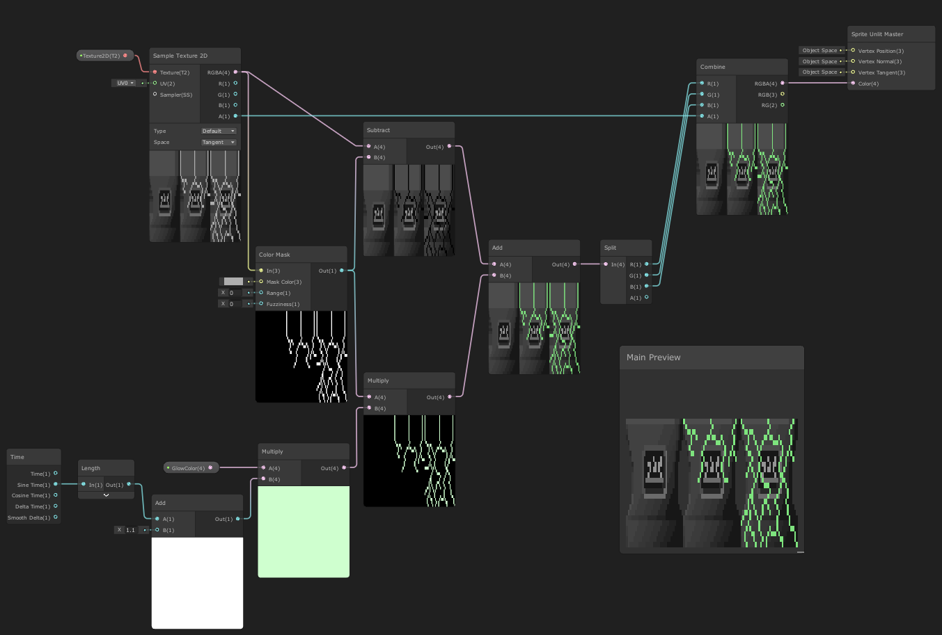
Im trying to make an adjustment to my glitter shader 🤔
When there is very few glitters, its very glittery
but when you turn down the power to have many glitters showing, they are individually way less glittering.
The circled value in power controls that scale, but I want to be able to control the number of glitters and the intensity/frequency separately 🤔


Is it maybe something about the normal vectors I am using to determine when to glitter or not? 🤔
Im having a hard time describing or visualizing what I mean. When glitter is this dense, nothing seems to change as much compared to when its very sparse.

The frequency of glittering vs. the density of the glitter flakes 🤔 I want to be able to adjust them separately
so far attempts to put power or multiply nodes at very stages have not had the desired result
multiplying after the power just makes it look pretty bad - everything is mega bright and many of them dont glit on or off ever

adding more glitter by making the voronoi larger also makes the glitter smaller, so that doesnt work either 🤔
One person answered this already, want to see if there’s more answers, here’s the question #💻┃unity-talk message
i'm having an issue with shader graph + ui
the image is transparent when i try to use a material, and people are saying to change the canvas mode to camera but that isn't working for me either
what seems wrong here


any stencil shadr tips
I'm trying to make a 2 pass blur, but I can only see one in the final resulting texture
this in the scriptable render feature thing

The frame debugger shows both passes being rendered, but only the vertical makes it to the resulting texture
ok, fixed it - I was using the original color texture in the shader second pass, when I should've been using the temporary buffer texture
Could you elaborate what you mean? What are you trying to do exactly and why?
Well I am trying to make a normal map out of Simple Noise to give an object some lighting effects
And that will also require to make the shader into an image?
I think
You can copy the code from "normal from texture" node
Also found a picture, perfect, thanks my friend

No, it's not URP by default, I just converted it if I remember correctly. Or maybe I did nothing 😐
Its this shader with a slight modification to work with orthographic cameras as well:
https://github.com/IronWarrior/ToonWaterShader
GitHub
Source code for Toon Water Shader tutorial for Unity. Renders and animates toon-style waves from a noise texture and generates shoreline foam based off the depth buffer. - GitHub - IronWarrior/Toon...
There are differences in the rendering pipeline between urp and built in. It will not work out if the box.
The tutorial for the shader looks very neat
https://roystan.net/articles/toon-water.html
I'd say, follow it, and see when the problem actually occurs. There are also articles online on the differences between urp and built in.
You could for example check, if your urp asset is rendering a depth texture.
I'm also not sure that the urp draws a depth normals texture the same way built in does, so the replacement normals part of the shader might be busted.
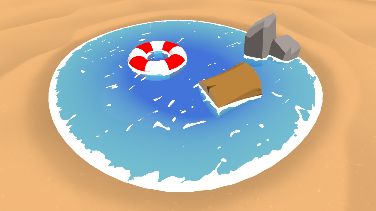
Learn to write a toon style water shader for Unity engine, complete with waves and shoreline foam.
Other, smarter people might have more precise info, what specific part is not working
Yeah, I reading the tutorial again, but to no avail. I guess I'll try to reconstruct it step by step. Thanks anyway! 🙂
When the flake normal is pointing within a small range of directions, it sparkles; the range of directions is determined by the power. So if you make the power larger, the range of directions is smaller, and so the number of glitters that happen to end up in that range becomes larger.
One way to get around it would be to go into the code (since shader graph doesn't allow loops), estimate the rate at which flakes would have the right range of normals (based on the power) and then run a for loop, randomly generating new normals and then adding glitter from those, to make up for it
Has anyone maybe experienced an issue where a Compute Shader works perfectly fine in editor but completely hangs in build, specifically iOS? It doesn't even crash, it just completely hangs the app - I've switched from GetData to AsyncGPUReadback and messed around with numthreads but apart from these two I don't see a reason why it wouldn't work - oh also the iPad I'm testing on does have Metal so it shouldn't be a hardware issue (maybe?)
Not all platforms support compute shader or its dependencies or whatever
it is iOS with Metal though so it should work

Is Metal being used though?
how do I get the standard geometry in a geometry shader? I want to add onto the original shape
what do you mean?
this is how I get my random values at the moment, I am not sure how do "estimate the rate at which flakes would have the right range of normals (based on the power) and then run a for loop, randomly generating new normals and then adding glitter from those, to make up for it" in code though


Studying the glitter carefully though I noticed that each flake only glitters once per rotation
Each individual dot only shows up one single time, maybe there is a way to alter that range so it blinks more times?

I tried various math on these bits but I wasnt able to get it to blink more than once

every time I try to alter the values, no matter where I do it, the only result is making the end result way more bland/washed out/intense

I cant seem to find the 'place' where I can alter frequency and not intensity
all I want is a slider that can take this, and add more dots

without affecting the intensity of any of the dots
cos(x) near x=0 (where the flakes are bright) is approximately 1 - (1/2) x^2; so this has a width of, say, 1 (where the second term equals 1/2). When you put that to some power N, and assuming again that x is quite small, it becomes approximately 1 - N/2 x^2; this would then have a width of sqrt(1/N).
Now, since this bright spot is roughly circular - it doesn't matter whether you rotate it around the normal of the flake - so the 'area' of the bright spot would go as the width squared - so just 1/N.
So roughly 1/N of the flakes are bright at any one time. If you want the number of bright flakes to be independent of N, you then need to add more flakes. Voronoi noise would probably be too slow to keep repeating, so instead you can cheat, and give each flake multiple normals (using a for loop). If your target fraction of bright flakes is F, you then need NF normals, so you set up a for loop to run int(FN)* times and give a new normal each time
*int() can be floor, ceil, round, whatever.
but you will have to write HLSL code for this
What is N exactly? the normal?
N is the power
Also if F^2 becomes comparable to 1 (a large fraction of bright flakes), you will have some flakes be bright twice; might not be what you want so you could do max(current flake brightness, new flake brightness) or something
Donno aboout iOS, but for android platform you can select the the preferred graphics api. Perhaps on the iOS is it's similar?
Correct me if I am wrong but I am not seeing why giving them even more normals is the only way, that doesnt make sense to me. Correct me if I am misunderstanding something but :
1: When the power is low, the range at which the sparkles show is 0 at tangent vector and 1 at perpindicular vector
2. when you increase the power, the range at which the sparkle shows up gets super narrow
3. why can't I just repeat the point at which they show up more frequently as in 3?

some kind of fraction modulo or whatever forces ranges of value to repeat to the view angle?
You can; though idk how to end up with nicely distributed spots without getting rings or something
How would I do that? 🤔 Maybe it will be fine and any rings won't be noticeable
Acos(dot product) gets you the angle, though I've heard acos is bad for performance in shaders. But whatever; if it's only once it's probably fine. Then you can multiply by some number, and do cos() and it should work
And saturate after the cos
(then divide the power by either the number of rings or sqrt(number of rings))
wait is Dot Product slow and bad to use? 😨
because I have been relying on them - a lot -

Dot product is fine
acos is slow
Dot product is just three multiplications and two additions
"Acos(dot product)" dot product is not acos?
dot product is not acos, i meant acos of dot product
Oh take the acos of the dot product, okay that was not clear
neat, okay setting up the other steps now

Hmm something weird is going on
Is this the right sequence?

You have to lower the power by the same factor as in the multiply
(or perhaps the square root, not too sure)
either way, power goes down as multiply goes up
bc both act to make the bright areas smaller
Like this?

swap the top and bottom inputs to the divide
the float going into the multiply should be in the bottom slot
of the divide
Its still doing something weird, maybe I need the square root like you said
its got an extremely obvious 'wave' of bright values as it rotates on top of the regular values

if I increase the divide higher than 2, the whole thing goes berzerk
the top input to the divide should be ~100 or something, what you had before as the power
but idk why that wave is there, that's weird
the top input is 150 atm
is that smaller than two?

once that 'wave' appears it just overtakes the entire cube
lowing the divide value seems no different than lowering the power value
i feel like there must be some bias in how the normals are distributed or something?

to the best of my knowledge its completely random values from -1 to 1
could you try removing the matrix multiply?
also put the remap before the normalize i think
Hmm removing it does appear to have removed the 'wave'
that was there because I was told to put it there, I have no comprehension of what it was actually doing
where does the square root go if I was going to try it?

right now if divide goes above 2, like even 2.1, the entire thing just becomes full sparkle noise
in the bottom one

and if it goes above 2 you should get more sparkles; at 2 you start to get each sparkle being able to sparkle twice, and more than 2 you have more than 2 opportunities to sparkle
if you increase the power float you could damp down more of the sparkles and reach balance
Damp? I am still having problems with the power value
If I take 2 and make it 3, I have to change power from 150 to like 1500

or else its just flooded
I feel like something must be wrong
because if you say 2 is twice and 3 is three times
then why is 2.1 causing there to be like 700% more sparkles
it should only blink 2.1 times if this was working as described
Im not blaming you here either, im pretty sure I must be implimenting it wrong
the rings do take up a much larger area than points which might explain it?

yeah if you set the power to 1000, there are ~200x more sparkles if the multiply is 3 vs if it's 2
before after the dot product there was also an exponent and mult by 0.5 which is no longer being done

I dont know what those did but I was told to do it
so maybe they need to come back?
the exponential is functionally the same as saturate()
it's just a little bit smoother on the edges
but for large powers it should look the same
but if the multiply is 30 and the power is 1000, and you reduce the multiply to 20, you only decrease the number of sparkles by ~10%
I dunno why the mult 0.5 is there only that without it, or at different values, it looks completely wrong
(so it works as expected for large values)
it's just when it's small it acts up bc it's a relatively big change
2^1 = 2, so to stop it from going to 2^100 in the power, you halve it; then the maximum is 1^100 which is just 1
Ah
I don't know how to use the square root, when I put it where you said, it didnt fix 2.1 being enormous

i'm not sure if it needs to be there or not
when divide is between 1 and 2, there are LESS sparkles
and then after 2 suddenly its just all sparkles
something is 100% wrong with this formula
but I have no idea what, only that it does not do what is advertised
and I have no idea why or how to correct it
maybe this is related?

if I dont absolute the view direction, the sparkles are completely wrong
absoluting it fixes it, but I dont know why it fixes it
50% of the sparkles are not visible without doing this
I assume its becaues their random vector is pointing inward or something
hm not absoluting and not remapping it to have negative values seems to cancel out, unneccessary steps?

i think that's because after 2 you go from having a point to a ring (much, much larger than a point - by a factor of order the power), and below 2 your point gets thinner but you don't get anything out of it
normalizing view direction also seems to be unneccessary
i think the length of the view direction encodes the depth in some sense so if you change the distance it'll be weird?
seems fine both in preview and scene
when I hook in the normalize, nothing changes
fair
also if you divide the power by the multiply number squared, then the peaks are the same width
(though you want power >> multiply number squared for it to work properly)
btw this is the sort of shape you'd expect for the number of sparkles as a function of the multiply number

divide the power.. by.. the number squared.. which number, itself?
the float that is 2.1 in this one
the one that feeds into the multiply in the acos->multiply->cos part

How do I do that? there's no square node
mult by itself I think??
I am an artist, not a mathematician if thats not already obvious
I hate to be a broken record here but are you absolutely positive this is making the glitters glit more often
specifically like this
https://cdn.discordapp.com/attachments/497874081329184799/1009453212446760970/unknown.png


because it just is not working at all not even remotely no matter how I look at it
am I stupid? Do I just not understand what im seeing? is it doing what its supposed to do and im stupid?
because its not doing what I want it to be doing
what I want it to be doing is as X value increases, there are more sparkles, linearly, not exponentially I guess???
but as I rotate the model the sparkles keep doing extremely weird shit
like very obvious waves of sparkles pass over it, or some sparkles remain pure white and never change
that to me is saying that its fundamentally broken and no ammount of adjusting values is going to fix it
Like when I rotate it
its VERY obvious that this acos thing is just adding weirdness to OTHER sparkles
but the ones affected by the power are completely unchanged
I am getting frustrated that were not making any progress and it seems to be only getting more convoluted and less functional, maybe we should just stop
nothing I do is improving it or resulting in the desired behaviour and its starting to affect my mental health because im a stupid failure as usual
and im too fucking stupid to fix it myself
so I have to rely on others
yeah i have to go im off the deep end now
thank you for trying to help me even though in the end it did not work
the entire thing is fundamentally flawed and worthless even before you started to help me

there is so obviously a massive wave that passes through it at certian angles
and that is throwing off EVERYTHING
and i have no idea whats generating it or how to fix it
its so incredibly painfully obvious
at the very least you helped me get rid of a lot of useless fluff that was doing nothing in the original graph even if its not doing what I want it to do

pretty much
They're distributed across a cube
That's why
You want them distributed across a sphere
Harder to do
You could write a custom node for it fairly easily
you can do that but only if you write HLSL yourself (and just give each flake multiple normals)
Remaining white probably means you're going along one of those rings?
Hey hi, i have some basic knowledge of OpenGL shader coding, tho its not very up to date.
Wonder if i should start HLSL with nodes then move into coding or start by coding.
What are your recomendations? If you could point out some up to date resources.
I started reading some of Cyan´s page btw
Maybe decide what's your goal first.
Is it just learning for the sake of learning or is there something you want to implement?
As far as i've read here and there, my main goal would be hand written URP, and checking shaderGraph in the meantime might be handful too, but secondary.
trying to boil it down to just the essentials to find out at its root where the weird shit is coming from - JUST the dot product and the UVs already produces weirdness

I dont know how it was -ever- working if its that broken at its core
The UV is basically a Vector2 with a 0-1 range so this isn't too surprising.
You really need a Vector3 with a -1 to 1 range.
oh okay, the random vectors were a vector 3, I just misunderstood the voronoi was a 2D UV and didnt notice it becomes 3d before going into the dot

I think the overall sparkly effect should be as follows:
- Generate flakes (using voronoi noise, with UV as input)
- Turn the cell value of each flake into a random Vector3
i. You could generate 3 floats each distributed from -1 to 1 and accept the fact that it won't be perfectly even
ii. You could generate 2 floats distributed from 0 to pi and 0 to 2 pi and turn those straight into a normalized vector3 using some trigonometry
iii. You could write a custom node to generate 3 random floats in the -1 to 1 range, check if the length of the resulting vector is <1; if so, normalize and return, if not, discard and generate 3 new random floats (if it takes more than, say, 3 tries, just output the normalized vector. You'll end up with some unevenness but probably not noticeable)
iv. You could generate 3 floats, turn them into a vector3, and then rotate it along a different random vector3 axis by some random angle - Calculate the specular reflection off each flake
i. If you want more sparkles at any one time, you can repeat 2 and 3 some number of times for a linear increase in sparkliness
ii. Or you can do the thing before where you convert to an angle, multiply, then convert back to add bright rings around the central specular peak
reading this now. I was also thinking something like this could somehow in some way help fix it

I guess having three floats with -1 to 1 might cause some bias towards the diagonal directions after normalising. I feel like it isn't too noticeable but maybe that's where the "wave" you mention is coming from
Could do, though I think the easiest method would just be to repeat the random normal -> add sparkle route some number of times.
I agree
Could try looking for methods to generate vectors on a unit sphere instead of a cube
iirc the fastest way is just 1) generate vector of 3 random floats between 0 and 1, 2) check if its length is <1, 3) if so, normalize, 4) if not, discard and restart
Arent if statements bad in shaders?
I guess, but "discard and restart" isn't good for shaders
Is it not quick to create 4 random vectors, 4 corresponding bools checking if their lengths are <1, then multiply the first three by those bools and the last by (1-OR(all the bools)), and then add everything and normalize?
Actually, iirc gaussian distributed components will be spherically symmetric
so just generate a bunch of random numbers and add them will be roughly gaussian
Idk, probably depends how you generate those random vectors to begin with. Using the Random Range method is still quite a lot of sin/frac/etc
True
What is the fastest way to generate a random number?
Maybe the random direction code from the Gradient Noise node would help here
float2 unity_gradientNoise_dir(float2 p)
{
    p = p % 289;
    float x = (34 * p.x + 1) * p.x % 289 + p.y;
    x = (34 * x + 1) * x % 289;
    x = frac(x / 41) * 2 - 1;
    return normalize(float2(x - floor(x + 0.5), abs(x) - 0.5));
}
I'm sure this could be extended to 3D (but haven't got time to look into it now)
Ill adapt my current random number value generator to work on the above there 🤔
Does it make more sense to do it three times on single value, or is there an easier way to expand that 2D vector into a 3d one?

Not sure. If you have (or can find) a library that generates 3D gradient noise they might already have done it for you.

you get in a single float from the voronoi cells, no?
Yeah I was about to say, I do have 3d noise nodes
3D simple noise takes in a vector3 though
perlin, simplex, voronoi, and white noise as nodes
you need to somewhat randomise the float to create two new ones
Isnt that what I was already doing?

I'm starting to feel like I am being guided into doing the thing I am already doing in order to fix my problem
but if im already doing it, its not going to fix the problem
It's a different method of generating random values, but yes it may have the same problem still :\
maybe I should add the object space position to the random noise in some way?

there's no glitter but at least the mask seems to be roughly in the place it should be
Also yeah, the 3d voronoi code should include a function that generates a 3d vector, so could look at that and see if that works better than your current method (3 x Random Float Value -> Vector3)
just mutiplying them together made a very obvious pattern 🤔

looking now
    float3x3 m = float3x3(15.27, 47.63, 99.41, 89.98, 95.07, 38.39, 33.83, 51.06, 60.77);
    UV = frac(sin(mul(UV, m)) * 46839.32);
    return float3(sin(UV.y*+offset)*0.5+0.5, cos(UV.x*offset)*0.5+0.5, sin(UV.z*offset)*0.5+0.5);
}```I think this is it?
Yea. Probably easiest to set up a Custom Function node using that, rather than recreating it in nodes.
Yeah as soon as I got to 'float3x3' I was like 'this is matrix math or something beyond what I comprehend'

its mad that something isnt being initialized

I forgot to assign to Out
but it still mad
    UV = frac(sin(mul(UV, m)) * 46839.32);
Out = float3(sin(UV.y*+offset)*0.5+0.5, cos(UV.x*offset)*0.5+0.5, sin(UV.z*offset)*0.5+0.5);```is this not right?
starting to think I should just do it in nodes
I hate fighting with @#$^@! HLSL code ,it never works and never makes sense
Looks okay to me. Probably need to give the function a name
I cant believe that fixed it
that is exactly why I hate HLSL
why would a name in any way matter or affect the code
completely illogical
Eh, it's more just the Custom Function node / generation
Functions need names or you can't call them, same for any language
I guess, I dont see why it couldnt interally have some kind of auto name

my voronoi noise I can control the size and density
but the new noise I just realized I was using the voronoi to also define the physical size and shape of the noises
Ah right...
so now I have to solve that 🤔
I could just use the 3D voronoi if its already doing random vectors?

the voronoi is already internally running the same function I am using to get my random vectors, so now its being run twice and that seems not efficient
Yeah, could edit the voronoi function (or a copy of it) to output the random vector. It probably already does that partially. (cells should be the x axis of it)
Ill see if I can do that
though the pulsar problem has returned as well and this time absolute didnt fix it - im starting to think that absolute never fixed it 🤔

notice its still pulsating even with the absolute, its just less
which is probably why I thought it fixed it before, I probably just never noticed that it wasnt fixed at all
oh
its because I didnt remap the values to -1 to 1
I'm hoping this is just because of the Cells (float) -> Random Vectors, but not sure

it doesnt do the pulsate if the random vectors are between -1 and 1 instead of 0 and 1
this is 'fixing' the pulsate b ut is it maybe introducing new different problems?
Oh right, the voronoi function is outputting them as 0-1 yeah
Removing the "*0.5+0.5" parts should change that
okay edit it to output the randoms, and remove that line
hurm
before I do that though
testing it out, its definitely not working

plugging it back into the nodes I had, there's still a very clear pulsation happening

the pulsate gets removed at Remap, and returns by the time it reaches Saturate
or im completely wrong and have no idea what im talking about and im misinterpreting everything I see
another reason why I hate HLSL, there's no way to debug anything, you cant just ask it to output whatever bogus values, I just have to stare at black and white colors and hope that I can visually debug it
you can't even see negative numbers, they're just black 🔥
its so @#$@ing frustrating that after like, a month of work the glitter still doesnt work
i've had so many people try to help me and its just fucked no matter what I do
im getting agitated again Im going to go into mental health crisis because I just cant fix this stupid piece of shit
I need it fixed, I wont be happy until its fixed, I need my efforts to produce results not waste hours of my life
its even more frustrating that I thought it WAS fixed
until I went and tried to use it for literally the very first thing, for literanny -anything-
and it just doesntg FUCKIWNETQ3946J
okay im leaving now
here have my stupid worthless piece of shit that im too fucking incompetent to make work
im obviously too fucking worthless to be able to achieve a single fucking thing with it
sorry im supposedto be shutting up and leaving , shutting off my pc
These are pretty complicated effects, if it's getting to you definitely take a break and come back to it when you are feeling in a better state of mind
So I'm organizing some texture atlasing - and I have a bunch of materials that share the same texture but have different colors.
I'm looking at the tradeoff between adding more textures to the atlas (adding multiple tinted versions of the same texture - potentially needing more atlases) - vs having more materials.
Any clues on how to figure out which approach to go with?
Have you thought about storing the colours in the mesh (vertex colours), that way it can still use the same material for batching.
Assuming for Built-in RP. As URP/HDRP would use the SRP Batcher so material instances isn't necessarily a problem.
too much work 😄
that'd make sense
pretty sure that's because they're not distributed evenly. Adding multiple such vectors would make them more even, but there are other ways of doing it too
the gold standard is 1) generate a random vector2 with components between 0 and 1, 2) multiply by vector2(pi, 2) and subtract vector2(0,1), 3) split to r, g, 4) output vector3(sin(r)*sqrt(1-g*g), cos(r)*sqrt(1-g*g), g)
if i've got my geometry right anyway
anyone know of a premade water shader that doesn't cause vr games to drop 50 fps when looking at it for a second 😅
urp
Hey I'm trying to get shadows on my unlit shader graph using a custom hlsl node like this
void MainLightShadowAttenuation_float(float3 WorldPos, out half Attenuation) {
    #if SHADERGRAPH_PREVIEW
        Attenuation = 1;
    #else
        #if SHADOWS_SCREEN
            half4 clipPos = TransformWorldToHClip(WorldPos);
            half4 shadowCoord = ComputeScreenPos(clipPos);
        #else
        half4 shadowCoord = TransformWorldToShadowCoord(WorldPos);
    #endif

        Light mainLight = GetMainLight(shadowCoord);
        Attenuation = mainLight.shadowAttenuation;
    #endif
}
Problem is that I can't get anything using my shader to receive shadows. Any idea where I should look for the problem?

Unlit graphs need keywords to make it receive shadows. Specifically, _MAIN_LIGHT_SHADOWS. Should also use _MAIN_LIGHT_SHADOWS_CASCADE and _SHADOWS_SOFT. Can set them up as Boolean Keywords in the Blackboard. (Global, Multi-Compile)
Alternatively, I have some SubGraphs that handle it for you here : https://github.com/Cyanilux/URP_ShaderGraphCustomLighting
@regal stag Hey thanks, this looks like the answer. I haven't gotten it working in my project yet though. Is there a reference for keywords like this that I can bookmark?
Whats the most performant kind of grass? is it best to make it with a shader?
Depends. A heavy GPU grass would eat up your GPU budget and might cause a GPU bottleneck. Statically/dynamically batched grass might eat up your CPU budget. Not sure about GPU instances one but I think it has more GPU than CPU overhead.
Rendering is always a trade off. There's no perfect solution.
is there something I can do to voronoi to get just the lines between cells?

this etc. I know voronois are distance spheres

I could take two voronoi, slightly off set, and difference their cell values maybe?
is there a better method than this?

ah yeah this method is not very good at catching lines that are parallel with the offset
can't you just take this part right here and run it through a step function
to capture the white parts
Step makes circles

oh that's kinda funny actually


im currently doing this huge mess but there has to be a way to do this that doesnt need three voronois
also Im struggling to figure out a way to make a mask to add texture that falls off from the cracks
Yeah thanks, I’ll try multiple ways I think
Can’t recommend anything but cool shader
Thanks 👍 the Cells' roundness is making it hard to mask around them because when I get enough of it around where I want, there's too much around other places

https://iquilezles.org/articles/voronoilines/ going to try to turn this into a node
it gives non-circular voronoi
I have no idea what im doing

HLSL is completely forieng to me, trying to copy paste the guy's code into the shape of an existing voronoi node HLSL is not working
his has no concept of angle offset or cell density
I hate that im too inexperienced to do this, but have no one who will just do it for me, and im completely unable to progress forward without it
so im stuck sitting here holding the bag, hating myself for being worthless, hating myself for not having friends who know these things and to them its easy
i dont think ive ever done anything in my entire life where the hard part wasnt done for me because im such a worthless piece of shit
time to go into menteal health crissi woo
oh boy its written in GLSL, I only have to learn TWO languages ive never seen before to make this POS work
honestly if you understand shader graph you're not too far off from learning written shader language

How do I replace the GLSL random2f with the HLSL random voronoi
"random2f" isnt a thing according to the internet google search
// Generate a pseudorandom 2D vector based on a 2D or 3D seed.
//
// https://thebookofshaders.com/edit.php#11/2d-gnoise.frag
//
// Inputs:
//   st  2D seed
// Returns 2D random point in [0,1]²
vec2 random2(vec2 st){
  st = vec2( dot(st,vec2(127.1,311.7)),
             dot(st,vec2(269.5,183.3)) );
  return fract(sin(st)*43758.5453123);
}
// Inputs:
//   st  3D seed
// Returns 2D random point in [0,1]²
vec2 random2(vec3 st){
  vec2 S = vec2( dot(st,vec3(127.1,311.7,783.089)),
             dot(st,vec3(269.5,183.3,173.542)) );
  return fract(sin(S)*43758.5453123);
}```random2 is though
great now i have to translate MULTIPLE files in two languages of which I comprehend neither
fucking shoot me in the forehead
i hate every moment of this
its like shoveling shards of glass into my heart
I wish I felt nothing so I could just make nice things
poetic...

The Book of Shaders
Gentle step-by-step guide through the abstract and complex universe of Fragment Shaders.
this is the only reference to random2f I can find
and it doesnt contain what random2f is
  return vec2(random(p.x+p.y*100.), random(p.x+p.y*1000.));
}``` maybe this is it from some random website
why is mine an Undeclared Identifier and theirs isnt
what did I do wrong
where is the mistake
oh boy HLSL doesnt have a concept of 'Random'
I keep going deeper and deeper into a wasteland of HLSL doesnt have whatever GLSL needs to work

line 158 has an undeclaried identifier
but its not even that many lines long
how do I fix it
its not the name of the custom node because I actually gave it a name this time
and its not that the names differ theyre the same

Ah. Okay
I think it was pissed this name was wrong

after changing it to be the same as the function
now its pissed that there's no matching 3 parameter function at 158
I dont know wtf is getting on about because

neither of those are 3 parameter
You don't return value like that in custom functions.
Your function needs to have no return type

Anything that you want to return needs to be as an out param
thats how this person did and it worked for them
Yep. That's the correct way.
how is mine different
they are identical
im too fucking stupid to see my own mistake, to me they're the same thing
Isn't that yours?
yes
it would be a lot more useful to tell me how they're different instead o- okay
wait what
They output data with out params instead of returning it.
oh it should be void and not float
fixed that, its still pissed about no matching 3 param

Yes. Might help reading on custom function node in the shader graph docs.
You still have only 2 params
And in the shader graph you use 3.

2 on the left. 1 on the right.
wtf is that x doing there its not even in this function
more stupid mistakes by stupid me
It's an out parameter.
As I said, you return things with out instead of a function return in custom node
I feel no joy despite getting it to work

thats the worst part of this anguish, even though the source of the anguish is now resolved, the anguish is still here
Thank you dlich for helping me through this troubling time
now I have to figure out how to give it the angle offset and cell density
OR I could just change nothing and do it externally

its late im just going to go to bed
ill feel normal in the morning
thanks again for the help
Could anybody give me the name of the HDRP/Lit properties for Tiling and Offset? I'm checking the Shader code but I can't find any vector or float related to it
I can see this :
[HideInInspector] _InvTilingScale0("Inverse tiling scale = 2 / (abs(_BaseColorMap_ST.x) + abs(_BaseColorMap_ST.y))", Float) = 1
But there is no _BaseColorMap_ST property in the file? Where does this come from?
Plus it's a hidden property so it shouldn't be the one I'm looking for.
The goal is to be able to change the tiling and offset at runtime. But can't find those 2 properties in their code. Quite strange.
How do you like it now? this is how I wanted it to work/look:
https://gfycat.com/granularangryelver


some of the cells are black
it can never be easy, it can never just work
here is my work, dunno how to fix the black holes though
also it uses two passes which is very not ideal
but https://iquilezles.org/articles/voronoilines/ they dont say how to impliment it in one pass
https://www.shadertoy.com/view/Xsyczh
https://www.shadertoy.com/view/tsfXDl
maybe something in here I can steal


With shader graph?🤔
could anyone help with this? i've got this blood effect, how can I remove the black background with alpha?

if I just plug this into the base color it's gonna obviously include the black background but I can't figure out the setup to get rid of it lol
I love it bro
Keep sharing progress
Make sure to ping me though 😉
Why theres no transparency in that picture to begin with, or is there? You have to plug the alpha channel to the Alpha block of the fragment stage
split the output of the multiply node and slap that "a" value into Alpha
Hey, is there an online tool or converter or anything that can turn a roughness map into a smoothness map?
I know I can use a one minus node to invert it, but I don't feel like making shader graphs if I can just change the texture (which I think will save space)
@naive shuttle Any image editing program which can invert colors works, online or offline
I used the invert button in paint.net, though it didn't give the same result as using a one minus node
Let me show the images
Using paint.net

Unity shader graph

What am I doing wrong here?
Invert and one minus are the same thing
I guess the color space used could change the appearance but I'm not sure
I would compare the methods in a scene instead of relying on the preview
Alright
If they really are different I would do the inversion in Gimp or Photoshop using linear color space
Also, how would I use a smoothness map in a normal urp material? I can only input metallic maps
It's either in metallic map alpha channel or base map alpha channel as defined by "smoothness source" dropdown
I recommend Gimp or PS for texture alpha channel editing as well

Does anyone know of any good tools for packing and messing with texture arrays in the editor? A quick search through the asset store didn't show anything up.
As a new Unity users is it worth using the ShaderGraph, or should it just use the options on the built-in shaders (ie "Standard" shader). I'm familiar with the node editors in Unreal and Blender, but the Unity ShaderGraph looks a bit different seems there is probably a learning curve, is it worth bothering with?
Depends on what you are planning to do
Nothing too crazy as I bake all my textures in Blender anyways
Unity has 3 render pipelines atm. built-in, hdrp and urp. First thing, is to choose which pipeline to go with
So basically materials use a texture/normal map/roughness map type of stuff
the standard lit shader (for built-in, hdrp, urp), supports all that. Its a pbr shader, so youll be fine
If you need more, then you can expand it with shadergraph
Shadergraph comes into play, if you want to add some custom features (like dissolve effects, vertex movement for water waves, wind for trees) and many other.
But at some point, you will cross the threshold, when it would be easier to write the shader from scrach, instead of using shadergraph. But overall, it's pretty good. Does the job. Has it's quirks, but it easy and fun to use
If you're in Unity 2021+ you can now import image files as a 2D Array (should be the "Texture Shape" option in the import settings). Input number of rows/columns and unity will slice it up for you.
Otherwise I have this which might work : https://gist.github.com/Cyanilux/e672f328c4cafb361b490a5943c1c211
I kinda disagree with that "cross the threshold" idea, especially as URP/HDRP doesn't have a surface shader replacement right now. So even if you know what you're doing, writing lit shaders can be quite slow.
But for anything that shader graph doesn't support (UI, stencils, colormask), sure
aye...but also, I often have this funny feeling, seeing a 30 000line shadergraph shader, that a custom writen shader could be lighter and way more performative
That looks perfect, thanks Cyan; just saved me a few hours!
Part of that code is usually split into separate SubShaders though to support multiple platforms. And Shader Graph does support custom interpolators (v12+) to move calculations to the vertex stage which is nice. I think the generated code does look quite bloated (with lots of functions for everything, even basic maths) but I imagine the compiled version isn't that bad.
But yeah, it is probably true that you can squeeze even more performance out of a hand-written one.
Inside of the custom node for that voronoi loops through all the positions twice
@tight phoenix haven't tested any of these but in theory they should all produce fairly unbiased random directions
Ill check those out
Is there a way to have a transparent material write to the opaque texture with shadergraph?
For context, I'm trying to blur stuff behind a plane. Transparent stuff doesn't seem to be factored in the opaque texture, no matter the render queue of the plane overlaying it. I can't get any info about transparent elements from scene colors and therefore my blur does not consider transparent elements
afaik not with shader graph, but when writing a shader, yes.
Can you share a bit of info on how would I do that? Does writing to the depth map also write to the opaque texture by default?
I did it by accident a while back; in the tags I set queue=transparent, but to stop it writing to the opaque texture you also need RenderType=transparent
If you just leave rendertype blank it's opaque by default iirc
Super, thank you @karmic hatch
I have a plane overlaying some objects in my game. That plane is rendered using the scene color. I need certain transparent elements to be rendered behind it.
My problem is that it seems to me that the only way a material will write to the opaque texture is if its render queue is 2500 or less (please correct me if I am wrong)
Now, whenever a transparent material's render queue is 2500, it renders 100% as intended when drawn on top of opaque geometry but if it's rendered on top of the skybox, its completely clear as if the skybox was rendered on top of it.
For one, I don't understand how the material can be rendered after geometry that's rendered after the skybox, but at the same time be rendered before the skybox?
I've tried writing the semi transparent material to the depth buffer, this time it renders over the skybox but will treat its background color as gray instead of whatever the skybox color is, presumably because it is drawn before the skybox?
Anyway, I'm hoping someone could shed some light on my misconceptions and how I could attain my goal of having transparent materials that are both drawn properly above the skybox and also part of the opaque map
The skybox is actually rendered after the opaque stage - as it would be a waste of performance to run the skybox shader on every pixel then cover them up.
This is why when you try to force a transparent object to be rendered during that stage, the skybox shows over it (assuming the object doesn't write to depth). And as you have found out, if you do write to depth, it blends with the grey colour used to clear the render target.
I haven't tested this myself, but the solution here would basically be, don't use the opaque texture. Render everything you want as normal. Then do your own copy pass in the "After Rendering Transparents" event. Can do this with a Blit in a custom renderer feature.
e.g. https://github.com/Cyanilux/URP_BlitRenderFeature - using Camera source, and TextureID destination : _CustomBlitTexture. Will also need to use a material/shader that samples _MainTex and outputs it directly to the Base Color (can use an Unlit Graph)
Your "plane" shader would then sample a global (aka not-exposed) Texture2D with the reference set to _CustomBlitTexture. And use Screen Position as the UV input.
That plane would need to be on a layer that isn't included in the "Transparent Layer Mask" on the Universal Renderer asset (as we wouldn't want to render it before this texture is generated!)
Can instead render that layer with the RenderObjects feature. Should also be able to use that layer (or another) for any other transparent objects you want to render after the plane too (maybe also with +1 to the queue)
@regal stag Thank you, that clarified everything -- much appreciated!
@regal stag Thanks for the custom nodes. I hate to bother you again but I'm getting this error on all of the nodes and it is going over my head. Do you know how to fix this? I put the folder into my project directly instead of using the package manager if that makes a difference.

Hey guys I am looking for help with a particular effect. I am fairly new but studying writing shaders. I have been searching for a way to have 2 environments live in the same space but only 1 is visible because the player is enclosed in an inverted sphere which its own shader that has a value with a range of 0-1. When that value is 0 environment 1 is visible and when the value is 1 then environment 2 is visible. looking for a way to have this as a vertical wipe sorta like a clip plane would behave.
Hmm, it's saying the SubGraph has errors, so if you double-click the node it should open it up, where there might be another error message?
It looks fine on the inside

Hm odd, maybe try re-saving it and then close & reopen the other graph
Otherwise might just be a shadergraph bug. 🤷
Sub Graphs have always been a bit of a pain to work with. Could try updating Unity to a newer version maybe.
It seems like restarting the editor fixed it.
I lied, it only fixed the ambient lighting node that I had placed. Any new nodes placed have errors.

Restarting with the new nodes placed did not cause the new errors to go away.
All the same error
Did you re-save the Ambient one? Maybe try resaving them all, then restart? 😅
https://github.com/Unity-Technologies/VFXToolbox This tool also can be used to compile images into sheets, for whatever purpose including arrays
You're a genius. No more errors. The previews appear to be rendering correctly.
Nice! Out of curiosity, what Unity editor version are you using?
2021.3.2f1
Hmm okay, maybe it's because I updated the package using a slightly different version (2021.3.7f1) and it didn't like it.
At least resaving + restarting fixed it 👍
I might upgrade and I will tell you if it makes a difference. I am having trouble getting results rn and I'm not sure if it is me or a compatibility issue. The ambient light node was not working so I had to use the built in one like I was before. Now I am trying to work the main light shadows node in and I'm having trouble getting it to work.
Actually I just thought to try applying the examples to check how they look. The toon shader you provide looks fine (aside from i think the ambient light not working) so it must just be an issue in my graph
Holy crap, it works! Thank you 🙂

Do you have any idea why some cells might be full black like this?

Im trying to fix whatever is causing this but I'm not even sure why its happening to begin with, where should I start?
bump
perhaps write both to textures and then pick from whichever you want to be using?
Is that the entire graph?
Yeah, the middle bit is a custom node tho. I actually just fixed the black dots by replacing the method in which it was generating randomness from the original one to one copied out of someone else's 2D voronoi node

that top randomness function was making the black squares - why I have no idea but replacing it removed them so it must have worked
2 render textures?
Nice!
yes
supports the stuff regular voronoi does now 👍

Though my "cells" results in the distance-based circular voronoi 🤔 and not the solid fill kind
So Ill have to see how to get that back

the only bad part about that would be that it is for VR
just store the x coordinate in the cell of the point whose distance you're using
How would I do that? This is the current cells function, and here is cells from a 2D voronoi that outputs the square fill bits


trying to figure out what the difference is
ahh hm I see theirs is storing the offset.x in res.y
res.y is a distance
Store voronoi_noise_randomVector(cell, offset) as a float2, then in the if (){} do Cells = voronoi_noise_randomVector.x
replacing d with r.x blew the whole thing up so that def wasnt it 🤔

I thought the above was doing exactly that but it made the voronoi turn mostly black
maybe I need to store it somewhere that isnt res.y
ill just make a new variable
nope making a new variable exploded the whole thing
Not res.y
Res.y is a distance that you are using
You can just put it in cells directly in the if()
Cells=r.x

that should work

Wait no
their code makes cells, my code makes half of distances
Create a new float2 to store voronoi_noise_randomvector
And then set rand=[that new float2].x
isnt that what I did with rand?
oh are you saying to not do the entire rand thing all at once here?
r also includes f which I presume is the fragment position in the cell

yes don't do the whole sum at once, calculate voronoi_noise_randomVector first, store the .x part in rand

Forgot a semicolon?


Did you put rand=storerand.x inside the if statement?
(though idk why it looks like someone put it through a shredder)
that shouldnt affect the left bit though
storeRand is never used in the main body 🤔
I dont know, was I supposed to?
Yes

Then it should work
this is confusing me more than if I had just copy and pasted the other one's function and tried to fix it
this?

but its going to assign to store rand every single loop??
I dont understand how this will work
it doesnt, purple checkerboard
Could send position + radius into shader and use alpha clipping. Something like this : https://www.patreon.com/posts/26438849
Though every material in the scene then needs to use that shader. (Or other shaders need to replicate that same functionality at least)
Could also look into stencils. Gives more control over which shaders/materials can be used, but it'll likely be much more complicated to setup (especially for a beginner).
I replicated a similar effect from a puzzle game, this twitter thread has some info : https://twitter.com/Cyanilux/status/1317566458558353408
In short, the idea there was :
- Render current dimension (sphere outside) - e.g. via RenderObjects feature if in URP. Or maybe some camera stacking + layermasks
- Render sphere with 3 passes - all with
ColorMask 0so it's invisible / only writes depth/stencil. Each pass has these ShaderLab settings :
Stencil { Ref 1, Comp Always, Pass Replace }, Cull Front, ZWrite Off, ZTest GreaterStencil { Ref 0, Comp Always, Pass Replace }, Cull Back, ZWrite Off, ZTest GreaterStencil { Ref 1, Comp Equal }, Cull Front, ZWrite On, ZTest Always, and vertex shader moves clipspace z for this 3rd pass. e.g.positionCS.z = UNITY_RAW_FAR_CLIP_VALUE;if in URP.
- Render next dimension (sphere inside), (maybe with another
Stencil { Ref 1, Comp Equal }? RenderObjects feature makes this pretty easy as it can override stencil values per layer - regardless of which materials/shaders used)
great now its STILL purple checker after reverting it
uhhh its still fragged up after reverting it

im getting tons of errors and all my old graphs are broken, hold on
ffs I closed the graph to reopen it
and now I cant find it again
and I dont remember what I called it
is there some way to find the most recently edited file maybe??? hold on trying to unfuck everything
float rand at the start, then in the if statement, rand = storerand.x
okay found it again

its still ripped apart so the code must be fucked in some way
im just going to revert everything and start from scratch
okay back to working, trying this


what is the difference bertween that working code and the commented out not working code
it doesnt look any different to me but its clearly different
why would running the function before have different results
As far as I can tell, nothing
Only thing I can think of is storeRand might not be defined as a float2
sadly it was

back to getting the normals, now I have to reintroduce the cells

hrm
looking at their code, I dont see why mine isnt doing the same thing

they randomize and store it as a float 2, and out res.y which is just that offset
but theirs has cells and mine doesnt

the variable names differ but as far as I can tell its identical logic
hm their loop runs on rand.x, mine is on rand.y

there we go
had to do it in the second loop, not the first one

mysteriously, the top one still rips apart the voronoi
I dont see a difference though, its gotta be some weird pemdas thing right?
theirs is almost identical

hm what's that float2(b) doing 🤔
for some reason this persons' code is using an int2 for b?
I guess converting from int2 to float2? Maybe just define the "b" variable as a float2
Tryin that now
Yup it fixed it
because reasons
🤷
all the voronoi

I think its done, here it is if anyone wants to use it for somethin
I dont think i have any more changes to do
I didnt know what to call the non spherical distance one 🤷♂️
I usually refer to it as "voronoi edges"
Technically you could call the circular/spherical one "Worley noise" too
@regal stag Sorry to bother you again. I'm having trouble with the shadow receiver node. Are you familiar with this behavior?
Discord wont let me upload my screenshot. So nvm while I figure out why that is.
Anyway, I can't get shadow receiver node to shadow receive and I was wondering if it depends on any specific settings.
Also I got an error that states:
There are 33 objects in the Scene with overlapping UV's. Please see the details list below or use the 'UV Overlap' visualisation mode in the Scene View or Lightmaps in Lighting Settings for more information.
which sounds relevant.
Oh I turned on shadowmask in the light settings and I got shadows casting on the toon material.
It sounds like your objects are using baked lighting. What GI mode to you use in the Lighting window? Shadowmask?
Hmm, Shadowmask is fine if you want the shadows to be baked. But the Main Light Shadows node should still work with realtime shadows 🤔
I tried to screenshot my settings but discord is not going to cooperate. Baked Global Illumination is checked, Lighting Mode is shadowmask, and realtime global illumination is off.
Well I'm not sure why it wasn't working before you switched it to Shadowmask. Unless it's something to do with the shadow settings on the Light component or the URP Asset.
how to get uvs in urp shadergraph? there's a UV node but it outputs 4?
Yeah... for some reason it's limited to UV0-3 rather than the full 8 channels the Mesh can actually store 😐
Just use the first two parts of it
x y
ignore z and w
UV0-3 are the channel, that's different
Kinda unclear if they are asking about the channels or Vector4 output, but yeah
I see
thanks
how would you do something like this in shadergraph
if (x < 2) { blah }
else if (x < 4) {other blah }
There's a comparison to get the bool, but then not sure?
I thought it would be branch but idk how
step node
that just gets the bool though, how do I then branch off and do different bits of code
But usually you want to avoid branches if you can
what's the blah and other blah?
usually it can just be a calculation involving multiplying that 1 or 0 by something
oh I see how branching works now right right
and this is just a shader to do some testing I don't care about efficiency
The Branch node isn't a "true" shader branch, so it's fine to use them
The issue was with my shadow cascade settings. Your package wasn't a part of the problem.
Do those curly brackets serve any purpose when defining a property?

Not anymore. It's a left-over from the "fixed function" style shaders from older versions of Unity (pre-Unity 5)
https://docs.unity3d.com/2019.3/Documentation/Manual/SL-ImplementingTexGen.html
But you do still need to include them or I think it'll error.
Something that further complicates things is that 2 environments are not identical. They are completely different.
MinionsArt's example can work with completely different environments. You'd just use the "appear" and "disappear" in two separate shaders for each environment. Rather than the texture swap, which does use the same geometry.
But I think you mentioned this is for VR too, and I feel like it's going to be really hard to get that to perform well. (iirc, using alpha clipping already removes some depth-testing optimisations that gpus tend to do).
Stencils would likely perform much better - as this is basically what they are designed to do. The method I explained should already work for different environments (but it still might be difficult to setup)
posting this here bc i put it in wrong channel

this is what the actual shader looks like in scene view, also idk why the scrolling for it is lagging

Any suggestions on how I could better replicate this sorta half mixed pigment look? my best attempt so far for comparison


I am able to make blobby stuff, but I am struggling to get it to look like the blobby stuff I want it to look like, and not just ANY blobby stuff
Im thinking I need a texture or something because thusfar noise alone hasnt reached the outcome I want
the above is mostly voronoi, gradient noise, and twirl node
maybe add two levels of gradient noise (one fairly high frequency, one low frequency) and then use that to sample a gradient with lots of variation? you could also multiply by some number and fract and then sample a gradient where both end points are the same so it can loop around
(specifically thinking of the middle top malachite looking one)
top right you could do by calculating the first and second derivatives* of gradient noise, then using those to rotate some distance around the peaks/valleys and then using that coordinate as a new input for more noise
though needless to say it'd be more difficult
(that should create the swirly patterns though)
assuming the noise is parabolic around a peak with some characteristic width r0, the derivative is 2r/r0 and the second derivative is 2/r0; so the radius from the nearest peak/valley (r) is the first derivative over the second derivative. Then we can subtract r from the current UV (or whatever is used as the input for the noise; if you use 3D noise this should be a vector parallel to the surface, and all derivatives must be parallel to the surface. It might look odd at the edges.). Then we rotate r by some angle, add the new vector back to the (UV-r) from earlier, and use that to sample a new noise
Note that I'm not meaning screen space derivatives, I'm meaning object space derivatives.
Also note that when you rotate, a constant angle might be preferable near the poles of rotation, where a constant distance would swirl things until they are a mess. In between, the second derivative goes to zero, and thus so does r - so rotating by a constant angle would blow up to infinity. How you go about navigating this (if you choose to implement anything similar) is up to you.
Layered perlin noise with distorted offset based on perlin noise might work.
I think Pink panzer was suggesting just that.
Here's what position + simplex noise offset -> simplex noise looks like

I was trying to think of a way that would get more of the swirls you get when mixing fluids; just adding position and a simplex noise offset looks pretty good but it feels too straight and not swirly enough to me
similar, in that it's adding a noise-based offset and then going into more noise, but trying to get more swirls
the expensive but 'easy' approach to get swirls would be to 1) calculate the derivative of the noise at a position, 2) cross the derivative with the surface normal, 3) multiply by a small jump length, 4) add this to the position and go back to step 1 until you've shifted far enough. 5) plug this final position into noise
and this also gets around the constant distance/constant angle problem
worst comes to worst it looks like position + simplex noise offset -> simplex noise
which frankly isn't bad
but in theory, for lots of very small jumps it should be quite swirly

Are you gonna keep reposting it, smaller each time?
Wtf
im not typung it all out again
and copy and pasting it is annoying bc im busy rn
scroll up a lil tho its bigger there
I don't want to be snide but others here are busy and this is annoying likewise
You could just quote the original post or post a message link
Hey there! Me again.
I have this weird problem. I have a fullscreen shader should output a modified UV map into a texture. I use it to create a painting effect, but it doesn't really matter here, for the demonstration purposes it's actually unmodified.
The problem is that map is totally fine in Scene window, and looks ridiculously pixelated in Game window. What can be the problem here?


Render texture has the same descriptor as cameraTargetDescriptor, and it's filter mode is set to Bilinear, so I'm at complete loss where this pixelation could even come from
To understand all the shaders in shadergraph I like to see the numerical representation of output values and what some shaders do.
Is this possible and used regularly?
https://assetstore.unity.com/packages/tools/utilities/shadergraph-extensions-debug-value-176735
There's some like this
But their utility is kind of limited, as shaders commonly to produce different values for every screen pixel which can't practically be logged into numbers
If I want to create a new shader graph to stack 8 textures + 8 normal maps max(I think that's the max sampling amount?), but with the number of layers being variable, what is the best way?
I think the only way to accomplish that with ShaderGraph is by leaving empty layers as black textures, as default inspector can't display texture arrays (at least, in 2021 version)
But if I recall correctly, you can write a custom inspector for your shader and set it manually from there
I wanted to see some output, because I'm trying to see the vertex position animation (wind) only when camera is close to the object.
If the player has a certain distance the animation should be 0 and not continue to be a negative number.
For now, I only achieved to do the opposite, with the divide node. Close is slow animation and further away the animation speeds up.
I tried to do the opposite with a multiply node, but things stays the same. How can I do the opposite and give the animation a min (Stop animation) and a max value?

In term of performances, is it heavy?
There will be some overhead, but I don't think a bunch of empty textures will have that much of an impact.
That said, I'd suggest testing performance anyway.
I believe what you want is an Inverse Lerp - T being for your Distance input, A and B as your Min/Max - or Max/Min if you need it the opposite.
(Could also use Remap node - which is the same thing but has an extra Lerp step which is unnecessary for a 0-1 output)
For either of these you'd then need to Saturate (to clamp between 0 and 1), as otherwise it'll extrapolate values.
An alternative is using a Smoothstep, which would have a smoother ease-in/out rather than being linear. That also already clamps automatically.
Sphere Mask would probably also work, that does the Distance for you too.
(For any of these nodes, can use the Node Library documentation to read up on them, if required. https://docs.unity3d.com/Packages/com.unity.shadergraph@12.0/manual/Node-Library.html)
Ok, worst case, I could just generate 8 different shader1, one for each number of layer and change at runtime
I'm trying to merge to gradient (color to transparency) together but I can't figure out how to get the proper alpha value in the end. It seems to only apply to the second gradient.

Not sure if I should use a maximum node to find the needed alpha in the resulting alpha. The idea is to have the same result as if we had two gradient layers in GIMP
Could you provide an image of what you want the result to look like?
I'm actually not sure now that I'm trying in GIMP lol
I'm currently using the HDRP Lit Layered shader and it's working fine so fat except for two points: It doesn't seems to handle transparency properly and I can't change the tiling or offset of the layers at runtime (can't find the properties in the shader variables).
So I was looking into shader graph to reproduce this shader without its 2 flaws
So however the HDRP lit layered handles the layered textures would be the way I need too
Not sure if that's clear
Thanks, I'll look in to that.
I guess I should start with small steps to get into it. Fist thing I notice is that applying a color to my white gradient gives a strange result. It should be full red going to transparency. But my shader graph makes it red to white to transparent for some reason.
I tried the different blend options but nothing works

You don't need to blend them. You'd just have Red in RGB channels and the gradient in the A component. But you shouldn't even need to pack them together as you'll probably need them separate for blending later anyway.
And the final Base Color & Alpha ports are separate too.
Well, that would work since the gradient is flawless, but what if I add some bumps in it and I need to keep those bumps for the final texture? I'll need to blend them then I guess?
Unless you need those bumps coloured differently, no
And if they need to be colored differently, then it's a blend?
I've got it working Cyan, thank you.
Only I did not consider that the vertex position would be constantly updated by camera <--> object distance.
So I now have a continue tremble of the leaves.

Maybe this is not the best way to make the animation stop?
That's the purpose of the Blend node, blending two Color/Vector4 inputs together.
It may be good to try to think of the RGB and Alpha parts separately (because of what I mentioned above, but also the previews in shader graph do not show transparency - only the Main Preview does that)
So rather than "A red gradient fading to transparent", it's "Red with a 0-1 alpha gradient".
You wouldn't want to use it to scale the noise. Use it to control the strength (Multiply on the Gradient Noise output)
How do I fix this ugly white outline around my oceans?


(The foam section seems to be the culprit here)
"fix"?
fix
remove
you see the single pixel outline around the mask of the ship?
Its because of the foamon the ocean shader
That's a conflict of the foam effect and the type of anti-aliasing used I think
huh
any suggestion as to how to cahnge the anti aliasing?
its weird
the effect isnt visable in the scene view
Scene view doesn't use AA
Try different types of AA, to see if it solves the problem acceptably
Or remove the foam effect from the shader entirely
Well I dont want to remove the foam
I just tried all three options ont he main camera
for anti aliasing
they all have a similar issue
Some AA may be enforced by quality settings in addition to camera's AA
FXAA for example shouldn't suffer from this issue but it reduces visual quality
Post processing anti aliasing shouldn suffer with that
I think msaa is the only problematic one
what does that mean
Of course, thanks, that make sense 🙂
Works now, awesome!
Assuming URP, it's the Anti Aliasing setting on the URP Asset.
The AA settings on the Camera are post-processing based and should work fine, as Aleksi mentioned.
ok
It is URP. Im trying to find the setting on the URP asset, but there doesnt seem to be one?
Oh, just a quick informative question about this.
Would this approach benefit the performance (stopping vertex position) if you should guess?
Or is is it negligible?
There a post process data settings propertie
but when I try to open an edit it
there liteerally no properites
That sounds like the Universal Renderer asset, not the pipeline asset


I don't think it'll have any effect. The noise is still calculated regardless of if the displacement ends up as 0. It needs to, because shaders run in parallel.

Haha!
Thank you so much for your help @regal stag
really appeciate it 🙂
got it working
So if I should do a performance increase, I should use script to disable the complete shader at certain distance?
Now I have this other issue while I'm here, I had a refraction/distortion part of the shader, that I could get working while the game was running. It would work in the scene & game view when the game wasnt running, but it wouldnt at all when the game was running.


(Obviously I havn't configured it properly yet)
I think it's the refraction, if it's a screen space thing, you could refract a pixel of ship into the water, where the ship is in reality the foreground. So then it has a very low depth - lower than the water surface in fact - so paints foam
There's an article on catlike coding where they briefly go through how to fix it
all fixed now
🙂
nice
but thanks anyway haha
Well, you can't "disable" the shader. Can switch it out for a different material - or easier to have the shader use a Boolean Keyword, which makes Unity compile it into separate versions. As long as it's set to "Multi-Compile" it can be toggled at runtime.
But then you still have some CPU side (C#) calculations in order to enable/disable keywords when you get close / far away. There's a balance.
Something that may optimise the shader is switching the procedural Gradient Noise node out for a tiling noise texture (Texture2D property & Sample Texture 2D LOD node). You'd also get mipmaps then, which may automatically reduce the displacement at a distance, removing the need for that distance calculation too.
What seems to happen, is that when the game is running, it creates a weird low res duplicate of the what ever its refracting, but unlike when the game isn't running, this doesnt move and change with the rising and lowering of the ocean surface (vertext displacement shader)
Your answer raises more questions, but that's something positive. One step at a time. Thank you!
Low res is probably bc the opaque texture is downsampled
@regal stag is there any reason your page breakdowns are all using ShaderGraph? Im learning to write shaders for URP from your page and wondering if this was just personal preference or if for learning purposes it was better to ilustrate breakdowns using shaderGraph.
I thought it would be better to learn writting shaders then move into shaderGraph, but i might be wrong.
Mostly just personal preference. I typically always use Shader Graph.
Would you recommend starting from there instead of directly writting shaders?
Reason i started learning how to write shaders instead of using graphs was just so i dont miss any "basics".
pd. i´ve coded some shaders in OpenGL in the past yet im not familiar with Unity shaders, read the intros in your page only.
Eh, idk. Having some basic knowledge of unlit shader code would probably be good. Especially as coding in HLSL can still be useful for the Custom Function node too.
Doing shader code first might also help show how the vertex and fragment stages are connected (as you need to pass data through yourself). But if you're familiar with shaders for OpenGL you might already understand that.
Unless you're in Built-in RP (which has access to surface shaders), it is kinda a pain to write lit shaders from scratch currently, so it's probably better to just use Shader Graph for that. Unless you want to do custom lighting models, then either is okay.
Most of the knowledge gained from the actual content of the shader will translate pretty well between the shader code and graph, so it doesn't really matter which one you use there.
Going URP now, im on BuiltIn planning to move on, so thats why i wanna learn (start using my own shaders).
Okay i understand, it was mostly the fear of skipping some stuff moving directly to shaderGraph
I thought of something. Give the second LOD1 a shader without the vertex-position.
#archived-shaders message anyone know the issue
No idea about the errors but they look unrelated to shader graph.
The previews are likely black because you haven't changed the Default values of the properties (under Node Settings tab of Graph Inspector, while a property is selected in Blackboard)
turns out gradient noise IS perlin noise 👀 Trying out yours and panzer's suggestions now today

Yeah, pretty sure that it's based on it. Or on simplex noise. Perlin and simplex are almost the same, just using different techniques.
what about the main preview?
it's grey when the shader is blue with a scrolling image and other effects
following your suggestions, already starting to get better results 👍

harder edge helps sell it, more like real paint. It does take quite a few node but im sure I can clean that up


okay now that im satisfied with this, back on trying to get Glitter to work 😬, starting with the randomness code you sent me
hi all! I'm working in URP and have a custom shader that is close to having the same options as the regular Lit shader, but does anyone know how to add the "Environment Reflections" option into a custom shader graph?

bringing in your node to see how it performs, having trouble setting it up

It seems mad about the name for some reason
renaming your method to have _float at the end fixed it 🤔
must be an HLSL/shadergraph thing??
probably
Shadergraph requires the precision to be appended to the function name. Should also be void and use out parameters instead of a return type.
https://docs.unity3d.com/Packages/com.unity.shadergraph@12.0/manual/Custom-Function-Node.html
Looks good, bringing in the other glitter logic now

Ahh I see "Part of the name this custom function has in the final generated code. Suffixed by the function type _half or _float."
also do u mean the mode or the default value
It uses the _ENVIRONMENTREFLECTIONS_OFF keyword, so you might be able to set up a Boolean Keyword with that
(assuming you can expose keywords that don't need to end in _ON now...)
in the inspector for each property you can set a default value
by default they're usually zero
so black
ok nvm but why does the scroll effect lag/pause sometimes
The scene view doesn't update materials constantly, to save on performance. There is a setting somewhere on a dropdown on the top of the scene view window to toggle it though.
should i toggle it or no
prob not actually
oh yeah also is there a way to make the shader of the sphere visible from inside it
Can change the Graph Settings so it renders both sides. (In the Graph Inspector window)
Hey, so i tried installing ShaderGraph, yet i cant go further version 7.4 from the package manager.
Is this limited to the Unity version?
Im on latest 2019
Yes, you need to be on newer Unity versions
damn okay, thnkx
how do i make it so it renders normally on both sides? when i do both its extra bright
both^

only rendering front:

Flip the normals when it hits the back side
That's because of the Fresnel Effect. You need to invert the normal for back faces. Can use an Is Front Face & Branch.

I think that should do it
Could also put the Fresnel Effect into the True and just leave False at 0.
o ok
why does this happpen tho it shows differently

the sphere isnt hollow btw if that changes anything
regular unity sphere
Probably haven't got the Depth Texture enabled on the URP Asset
The tutorial should really mention this. If it doesn't, maybe find a better tutorial creator.
I might be misunderstanding, but is it enough to have the keyword added into the graph as a property? I thought I might need to use something like a reflection probe node and connect it into the fragment block
I'm back this far, the glitter looks good, I am once again at the point of 'how do I increase the frequency without subtracting how many are visible'
Going to try to not lose my shit / lose my cool this time when it doesnt work

Would depend how your current shader is setup. Is it a Lit graph? Or Unlit & doing lighting calculations?
yep, its a Lit graph I'm using for the shader I'm working on
Then it'll already handle environmental reflections (based on Lighting.hlsl / GlobalIllumination.hlsl in the URP ShaderLibrary), you just need to specify the keyword which should allow it to be toggled
ah okay, so I can add the keyword in as a property and use a branch node for controlling it 👍 . Which would be the best input for the branch's output? I'm thinking metallic or smoothness?

As long as you use the _ENVIRONMENTREFLECTIONS_OFF reference it should work. As the code inside the ShaderLibrary is already using an #if defined() - (equivalent to using the Keyword node)
https://github.com/Unity-Technologies/Graphics/blob/4ccc5351ef4d264e7cf5d4cdab0024770dbc3740/com.unity.render-pipelines.universal/ShaderLibrary/GlobalIllumination.hlsl#L262
oh, great! I shall give it a spin, thank you! 😄
I cant keep bashing my skull off of this. I fundamentally do not understand how this works, and everything I try to do to alter the result, results in failure

I can already tell im severely agitated
all I want, I just want, a number, a value, one single thing, that changing this one single thing, I want this sharp angle appearance, except with X times more glitter showing

panzer was saying I needed to do some kind of loop that gives each spot multiple normal values but that sounded exccessive/way beyond me
I feel like whenever i do finally get this stupid piece of shit to work, its not even going to look good. Im going to finally get what i wished for only to find out its an x/y problem
the x/y problem being 'I want more glitter' and I just THINK this is the sollution to more glitter
yeah im already mentally compromised, Im going to go do something else for an hour
I would just repeat the process to generate a new normal and make each sparkle count twice
just checking - this method works with a Keyword node, right? I can't seem to find this node when searching for it in my shader graph and its definitely up-to-date 😕
tried also making a sub shader graph but it couldn't locate this node either
By keyword node I mean the node that appears when you drag the Boolean Keyword into the graph. But you don't need it in this case, as the ShaderLibrary is already doing the #if defined(). Sorry if that was not clear
ohhh haha, I was reading through the docs about the Keyword node 😆
well, I've got this, with _ENVIRONMENTREFLECTIONS_OFF set to 0 and _ENVIRONMENTREFLECTIONS_ON set to 1. Is this going in the right direction or have I misunderstood something? 😅 sorry if I have cyan!

oh wait I think I cracked it
You've misunderstood.
All you need is this :
In the Blackboard, create a Keyword -> Boolean (different from a regular boolean!)
In the node settings, set reference

oh my lordy I am a numpty hahaha
It is kinda inverted though, which is a bit annoying. (Ticking the field turns off the environmental reflections. But that's due to how Unity set up their keyword, so don't think we can really fix that)
Specifically it's because Boolean Keywords, when Exposed, use "[Toggle]" in the shader, rather than "[ToggleOff]" which is what the URP/Lit uses for this keyword
yep, just clocked that the Keyword was at the bottom of the list!
along with changing the metallic smoothness, I'm getting the same results now as the default Lit shader 
thank you so much for helping me with this, Cyan!!
I am back and cooled off. Proof of concept - doing it all twice and then adding them together increases the density and fullfills the 'multiple vector values'

so I just have to do this, but less dumbly 🤔
@tight phoenix I'd suggest using an Absolute node after the Dot Product. That'll take advantage of the negative values (when the random vector is pointing away from the view direction), so should double the amount of sparkles.
It's possible the Exponential setup is already kinda doing that though, I don't really understand that part.
I still think another solution though is 'instead of it glowing just once, it glows repeatedly at different angles
https://cdn.discordapp.com/attachments/497874081329184799/1009453212446760970/unknown.png
Trying this now

Makes sense. Could maybe try Absolute -> Multiply by 5 or something -> Sine (or Cosine) 🤔
Then maybe Saturate -> Power
it looks like the exponent is doing something like that, I also dont know why its there / what it does, that part was given to me
tryin that now
Doing absolute alone by itself seems to result is pretty much 95% the same as the exponential so Ill switch to that
Hmm

when I plug in the above, it removes all sparkles
they just vanish

im guessing it has something to do with white and black not being 1 and 0 but actually some way larger values??
sorry to ping again, but would Specular Highlights also follow this method?
I think so, with _SPECULARHIGHLIGHTS_OFF instead
if I understand correctly - the value multiplied by is how many times it will sparkle? Because 1 is none, and 2+ becomes just flooded with sparkles

I think I had the exact same problem last time I tried to fix this as well
I can feel the agitation growing again that im immediately all ready in the same dead end that I failed to escape from last time

different nodes, same result, no clue how to fix it
I want a value that is a linear value of X times it will shine based on angle

this set up is 'shines 1 time'
but how do I decouple amplitude, # of shines, whatever else from eachother
I did brute force more shines by adding another voronoi but this doesnt actually fix the real problem, this just creates more surfaces to catch the shine

more surfaces means more shines, but they each only shine once, so its the same problem just with a curtain over it
if I want it to shine multiple times, do I have to change the view direction? or the random values?
I have this currently, but not sure it's really doing what you want

Hm smoothstep, I havent tried that, copying your setup here 1 mo
Why use Cosine instead of Sine? my understanding of sines is that cosine starts at 1 and sign starts at 0 otherwise they're the same?
Does that do something different that I dont understand?
oh the results are different 🤔
different mult value shows difference

it keeps ending up just really intense

I have not found a set up yet that lets me control with a value the way I need
its always too little or too much

this gives me repetition but it doesnt work the way I want
I dont know how to describe what I want though
so far copy pasting the entire graph and adding two of them together has produced the best results

but is also the least usable and worst sollution, and it doesnt scale, if I want more I'd have to do it a third, fourth, etc time
Yeah I kinda also tried that, but instead of calculating a new random vector I just swizzled the components, which seemed to work
Ill try that now
Would be far cheaper than recalculating random vectors.
But still not really configurable with a float property.
Yeah :C
How did you combine the swizzle in?
once it exists, do you do the whole dotproduct + onward again?


at least this isnt duplicating the voronoi, which is the most expensive part
Yeah like this

we did that the other day and the rings made it go from some tiny amount to everything sparkling
well it did that because I'm stupid and most likely didnt do it right
I dont think that is the only result it would give
at its core, this is what the glitter is - except instead of object space its random vectors

No, that's how it would always go, it's only nice and smooth when the multiply value gets much larger than 2. At 2 it blows up.
if you say so
If you could write a for loop that runs all the sparkle stuff, and uses a component of the old vector as a new seed, that would be able to do arbitrarily many normals per flake
(So:
- Input voronoi cells
- Input power
- Input number of normals per flake
3.5 Start for loop - Create random normal
- Calculate sparkle brightness
- Add to output float (initialised to zero outside the loop)
- Use the r component of the normal vector as a seed to generate a new normal vector
7.5 End for loop)
@tight phoenix Hmm, how about this? Using Multiply->Sine/Cosine seems to basically makes everything sparkle a lot, but I realised we could then just mask some of that out using a threshold on the original voronoi cells output.
