
#archived-shaders
1 messages · Page 2 of 1
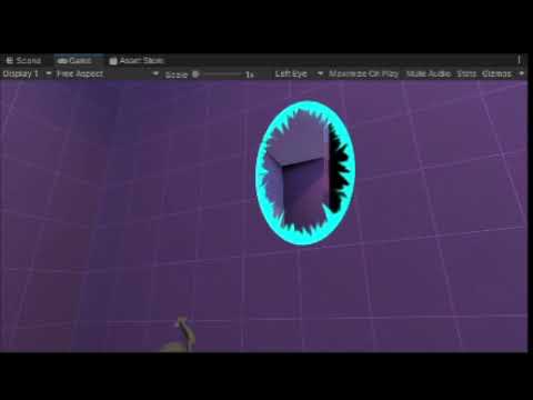
However, these points don't seem to change when I move or rotate the camera. I tried the same thing using unity_WorldToCamera and that caused the points to move around, but it's obviously not the right matrix to multiply these points by
Here is my code. Sorry if it's crappy, also the float2(1003, 564) is the screen dimensions for the current window, since using the _TexelSize.zw doesn't seem to be working.
#include "UnityCG.cginc"

#pragma kernel CSMain

RWTexture2D<float4> positions;
float4 positions_TexelSize;
RWTexture2D<float4> projectedParticles;
float4 projectedParticles_TexelSize;

[numthreads(16,16,1)]
void CSMain (uint3 id : SV_DispatchThreadID)
{
    float4 position = float4(positions[id.xy].xyz, 1.0);
    float4x4 projection = unity_CameraProjection;

    float4 projected = mul(projection, position);
    projectedParticles[uint2((0.5 * projected.xy + float2(0.5, 0.5)) * float2(1003, 564))] = float4(normalize(position.xyz), 1.0);
}```(this actually generates a texture which I then add to the screen, but that's not super relevant, as I know it's an issue in this compute shader)
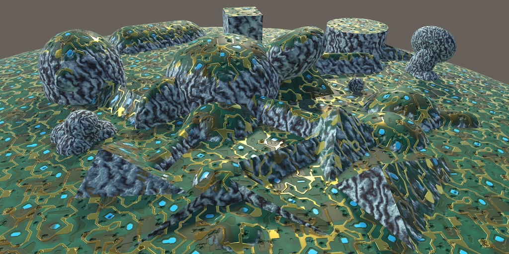
Is there a way to put procedural textures on a mesh without using a uv map? (no seams and the such) similar to how you can in blender and substance. Example below

Procedural texture meaning noise
Make a triplanar shader using shader graph
It takes a image texture, i'm trying to use simple noise and the such
Will it work the same?
Yes
Okie dokes
Sorry, bumping this question again because I am very stuck. Let me know if there's any more information I need to include/clarify.
anyone know how to fix this weird uv thing in a close ended sprite shape

nvm setting height of all points to 0
worked
ok another question anyone know how i can get as close as possible to a color ramp in blender
what ive got so far is this but the colors i choose arent exactly the colors replacing white and black

Hey so i need some help with merging code from two different SRP shaders but I have no idea how as i don't know anything about how to work with them
I've tried but it didn't work and i have no idea how to do it, can someone help me out?
You could just lerp in case you want to use two colors so black is one color and white is the other one
You can try setting all verts to (0,0,0) in the geometry shader to cull the polygon. But then again, you could just not emit it....
So your question is confusing to me, no offense.
What type of culling do you want?
I'm trying to understand if I should perform out-of-view checks on the input vertices inside the shader at all, to make it not produce grass blades outside of camera's view
or it's a stupid idea and I should always output same geometry for the input
I don't know if that makes sense at all
For some reason, i am unable to change the material on this sprite, what am i doing wrong?

I don't understand. If your positions are in world space, they're not supposed to move...they're in world space.
Or maybe you mean they stay the same place on the screen even if you move the camera? In that case, take a look at the Unity_ObjectToClipPosition macro usually used in a vertex shader. You won't need the Object2World part of it, since you're already in world space, but you need the view and projection matrix. UNITY_MATRIX_VP.
https://docs.unity3d.com/Manual/SL-UnityShaderVariables.html
https://docs.unity3d.com/Manual/SL-BuiltinFunctions.html
There's also a UnityWorldToClipPos macro that you could run in a normal vertex shader that you could run in a full screen pass:
inline float4 UnityWorldToClipPos( in float3 pos )
{
    return mul(UNITY_MATRIX_VP, float4(pos, 1.0));
}```
Which you could use to transfer your WS data to the screen without a texture, or write to the texture, no compute shader needed.

But IDK what you're doing to transfer all that to a texture, and don't forget about the perspective divide that happens during rasterization (dividing xyx by w).

I think. 😉  At least it will give you some matrices to play with.

Anyway, it looks kinda cool from the pic.  🙂
That does make sense 🙂
Well, what happens is that the GPU automatically clips things that are outside of the camera frustum. Of course, the fewer calcs you have to do, the faster the shader is (the fastest polygons are the ones you DON'T draw).
That said, if you have to jump through hoops just to cull the polygons, you may be spending more time figuring out culling than you would just letting the CPU cull it. The only way to tell is to run benchmarks both ways. Which means you have to write and test the culling code. Sigh.
Anyway, that's what vertex shaders do. They convert everything to CLIP SPACE. And if the polygon is outside of the -1 to +1 range in all dimensions, the polygon is not in the frustum.
yeah, I was wondering if I should output from geometry stage unconditionally and let the later stages cull everything that's out of view
or perform additional checks for every input vertex and not output anything for out-of-view vertices
checks guaranteed to add more calculations
but I have no idea if less geometry from the geometry stage saves much performance wise
but yeah, seems like I need to benchmark that
especially because I want to test a version w/o the tessellation stage so I can target shader model 4, instead of 5
still not sure if I want to target 5 or not
OK, yeah hard to tell, but I'm guessing you might have a win, it all depends on how many out-of-bounds polygons you'd have in the first place.
The real trick, if you can find a way to pull it off, is to NOT use a geometry shader stage. They're slow no matter what.
But then you get into procedural geometry...
SM4? OK, maybe see if you can do it all procedurally like with a compute buffer full of points or something. But don't let me side-track you.
I think you can pull that off in SM4
yeah, no worries, I'm still not locked into geometry shaders, just researching all the options for the foliage rendering
im trying to remake this effect my friend drew in procreate of rippling cloth banners but idk how i would do that with a sprite anyone have suggestions?

my first thought was normals but i plugin a scrolling noise texture and nothing happens
yea... it's a bit of rocket science for me, I got this shader from a youtube video and I'm still learning about the urp. I can' t figure out how to add my UV (which should be the first node on the top left if im not wrong) ad Vector2. And also this would only apply to the sprites that I allow, right? If so, isn't there a way to make it apply to all the sprites?
if normals work on a sprite, you could just use shader graph and put sine(time + position) into a normals from height node but maybe normals don't work on sprites?
normals do work i just want a way to convert the noise functions into a normal map

so it will be tileable and i can have control over all the variables
There's a normals from height node, but I wouldn't use noise, I'd just put in a simple sinusoid
There's a node that takes in a grayscale heightmap and spits out tangent space normals; if you just do sin(time + position) and put it into the normals from height node then it should give something good
Maybe multiply by some height difference so it's not waggling where it's meant to be attached to the wall
(by position, don't just whack in the vector3 but maybe add x and z components; also multiply both position and time by frequency parameters)
by position you mean this?

no, basically take the dot product of the position and some vector2 (which you set to be a property so you can change it), multiply the time by some float (another property), add them together, then put it into a sine node, then a normals from height node (strength of that can be a third property) then put that as the normal
finished the culling-enabled version of the shader, it is so much faster now ❤️
went from 65-80% GPU load down to 30% (which is almost the same load when foliage is disabled altogether)
closer?

Yep
yeah you could scroll gradient noise across
if you want it stretched along some diagonal axis you can do the dot product thing, cross the property vector with (0,0,1), then dot the position with that vector as well, and now you'll have 2 coordinates in a new diagonal basis
and you can then stretch one axis (multiply by some scale <1), add the time to the unstretched one, turn it into a vector2, then feed into your gradient noise
something like this?

Yes exactly
where would i plugin this dot product tho
would i just add it where the other one is added
this dot product tells you how far your position is along a direction perpendicular to the direction the flags wave along, so you want to multiply it by some small value, then put it into a new vector2 with the other dot product
then add time multiplied by some vector2, and put the result into the gradient noise node
np :)
noob question, don t know if here is good to ask, sorry if my topic is not good here
how can i make an effect for that blue image to looks like is coming from the edge of the screen, orrrr to looks a bit different from the background, thanks


I'm having a problem with a normal map that I'm not sure how to solve
the normal map gives it this square texture instead of smooth
if I SUPER crank up the contrast, that grid appears

but even after gausian blurring out that grid from the texture, the square grid still shows up in Unity

Ive tried various settings on the export, import, filetype, I cant seem to eliminate the squares
 instead of putting the texture in the sampler node directly, I put it in its own node, and set that node to Bump instead of White, and that fixed it

weird, but good to know that affects it
scratch that, it stopped working immediately
maybe I misunderstood what I was seeing
Hey, Im trying to make a dry up effect for a clay kiln, although Im getting some weird effects with the normal map. The 3rd pic shows how it's supposed to look (with the 1st pic as settings), and the 2nd pic shows my shader material settings, and the 4th pic is how it looks with the shader material...


Here's the shader graph

Im using URP
Change type from default to Normal

and make sure the texture itself is also set to being a Normal

I have the node graph for a signed distance cube, but I am struggling to change it from UV space into Object space

here is an object space graph for a spherical distance field, but I cant seem to figure out where to plug which part of my cube into this to get cube instead of sphere


if I try to plug in my signed distance cube in in place of the object space, instead of getting a cube, I get eight circles at each corner of the cube
and im not competent enough at vector math to know why or how to fix it 🤔

Output = length(max(abs(p)-b,0.0));
are the four nodes on the bottom equivalent to that formula?
the length of the maximum of the absolute of P minus B and zero?
the output appears identical but I cant be 100% sure I did it right
One quick question while I was writing some lighting in the shader…
Why do we use world space normals for lighting calculations ?
Simply put because the light direction is in world space
Hello I have a water shader which is using a sine wave to displace the geometry of the "water plane" mesh it is applied too. How would I go about optimising a large water plane? Currently my scene (which is nothing but water an a blank terrain) is rendering with ≈ 310 FPS
How could I optimise this? Simplifying the water plane mesh depending on the distance from the camera vertices are? Find a way to cull the verticies what exist under terrain?
Both options are great optimizations yes
great! I need to find a way to do those things then 😔
Rather not simplifying it but tessellating it closer to the camera and not tesselating further away
Splitting your water into chunks and only rendering the vissible ones is also a option
I have attempted to split the water into chunks however the sine waves don't match up
You need to transform it into world space


Working on this again today, trying to turn your instructions into nodes and I'm getting not the same results so I must be making a mistake somewhere.
Pictured is the Anistrophy, and the vectors perpendicular to the cube's faces


what am i doing wrong here? ive got an object space normal map that i baked in blender, when i try to use it in shader graph it doesnt work properly


for reference heres what it looks like without the normal map

I don't really use object space normal maps but it might be because the Transform node should be Direction mode
But you also should be able to just change the Fragment Normal output space in the Graph Settings to Object, that way you don't need to do the transformation


It's also might be that the vector need to be swizzled, as I know blender & unity use different axis.
There's a Swizzle node
oh wait cool
return vec4(subColor, 0)/(1.-0.7*dot(direction, SUN))*0.4;
re-creating this in shadergraph, what does 1.-0.7 mean and how do I represent that?
one point negative zero point seven?
source code is shader toy
Or maybe it doesn't need swizzling but needs inverting. I think the Y might be flipped 🤷
do you know what i should use as the mask for the swizzle?
oh
uhhhhhh i cant delete the swizzle node for some reason
something is very broken after adding the swizzle node
I think 1. would just be short for 1.0
Ahhh that's the one I missed. Thanks!
Ah okay ill try that
why would they write 1 minus 0.7, and not just write 0.3?
Probably don't need the Transform node. But you'd change the Space from Object to World on the Position node that is going into the Sine (or if it's using UV, swap it out for Position)
changing it changes the result 🤔
Because it's not 1.0 - 0.3, it's 0.3 * dot(..) then 1 - that
Ahh I see
https://www.shadertoy.com/view/NttcRr
I'm trying to re-create this in shader graph, I managed to do just the Subsurface part but the mainImage code is way too heavy for me


im pretty sure the nodes are right, its just a matter that im not sure what im supposed to pass in
For the anisotropy, don't add 1 to the strength (the dot product should go between -1 and 1, so if you multiply by something larger than 1 and add 1, it can go negative, which you don't want)
Oh hey Pink, I am trying to build your shadertoy in SG
i see :)
Not having much luck though, I read all your verbal comments and tried to make a graph of them but you were saying do this, no actually do it in this other order
I wasnt able to reproduce it
I can try changing this but its probably better to throw out all of that work because its based on your verbal instructions, not on any understanding of what I was doing
Like this?

Im definitely doing something wrong in that graph because the effect gets stronger the closer my camera is to the object
and not based on view directions
view direction node must not be what I want
object, world, view, tangent all produce crazy results
So basically what I had in terms of the subsurface color/brightness is:
- get whatever value you're using for the distance the light travels through the cube to reach the surface
- Remap it
- Multiply by the absorption color
- Negate
- Exponentiate
- Hyperbolic tangent to normalize it
- Multiply by an intensity
- Calculate anisotropy
i. Dot direction and sun direction
ii. Multiply by some float <1
iii. One minus
iv. Reciprocal - Multiply the subsurface intensity by anisotropy
I havent even gotten to color yet, I am just trying to map the angles
Add 1 after the multiplication
trying to do all of it at once is making me unable to figure out what does what
Done

for some reason the preview looks completely different to the actual model in a scene
strange
preview is mega black and white

model gets lighter the closer to the model I am, darker the further away

but otherwise looks shaded more or less normally
the entire graph is just me trying to debug the angles

ah okay
Okay it seems to be working-ish now, or at least isnt producing crazy results
Nice
its just kinda completely lit now
definitely looks nothing like this


without the ansio it looks like that
I have tried this but it is still not working

Seems to be working at least
the problem is probably because these ansio values are not for the color but for attenuating some other part I think?
the other part I have not yet gotten to?
Yeah it just multiplies the subsurface intensity

Doesn't do any of the work in terms of colors
here is the hyperbolic tangents bit, the end result of this would get multiplied by the anistrophy
That would just be a constant if I am not mistaken?
I feel like my mistake here is that there's no concept of the cube in there anywhere
You need some function for the distance through the cube that the light travels
here is the signed distance field of the cube, it works as expected

would this be that function?
What I did was I calculated the distance from each face multiplied by the brightness hitting that face, and plugged that in
I do have brightness to use

MainLightIntensity would just multiply at the end
let me plug that in I think I understand

I'm not sure what the second value in distance would be here
hm wait this is distance from the UV map, not from the object's faces
float fromFaceA = dot(axisA, position)*dot(axisA, SUN);
float fromFaceB = dot(axisB, position)*dot(axisB, SUN);
float fromFaceC = dot(normal, SUN);
where SUN is MainLightDirection, and AxisA and AxisB are vectors perpendicular to that face
(AxisA and AxisB you can get as AxisA = ObjectToWorld(ObjectSpaceNormal.xzy) and AxisB = cross(AxisA, normal))
Thats a lotta dot products, give me a sec to try to set this up

SUN direction is the value coming in from above
Axis ABC though im not fully clear on. I put in the SDF cube side for that?
I should make a subgraph passing in the sun angle for this to make it cleaner
AxisA is just a vector perpendicular to the normal (but aligned with one of the other faces) and axisB is a vector perpendicular to the normal and AxisA
vector perpendicular to the normal... so I need the cross product of... something?
the face normal and the view direction?
I have no idea how the SDF cube representation factors into this
Object space normal.yzx is object space AxisA
This?

Thank you for your patience by the way, I know I don't really know anything or what I am even doing
Do you have the normal to the surface?
is that the normal vector extruding from the face of the mesh?
yes
This then I think

indeed
let me scroll back up and look at the formula from before
float fromFaceB = dot(axisB, position)*dot(axisB, SUN);
float fromFaceC = dot(normal, SUN);```
so position in space, and object normal, I have those valuesMight be convenient to just turn the main light direction into object space (i believe the node is called transform?)
Ah yeah I am familiar with that
And then just do everything with the object space position and normal
I dont actually know what space the light direction is in, let me check

Ah okay thats World Space
ill transform to object space
How can I triplanar map noise textures to an object? I'm trying to get procedural textures without any uv unwrapping
do I want position or direction?

Direction
Direction I think yeah
Position also translates it depending on where the world space origin is compared to the object space origin

is Axis A is object position, what is axis B?
let me scroll back up and make sure thats what you said
Axis A and Axis B are both vectors perpendicular to the normal, but parallel to the normal of one of the other faces
They're mutually perpendicular
It's easy to get one perpendicular vector by just swizzling the object space normal
so rather than normal.xyz, swizzle to normal.yzx or something
Okay got my swizzle, setting this up


I think this is right??
let me look at the shadertoy what to do with abc once I have them
face A should have the swizzle, and face B should have cross(axisA, normal)
Hey, I'm trying to apply smoothness on a material using a voronoi texture, so that the white spots are smooth, whilst the dark spots arent. I want to add a sort of drying up effect, as if clay is drying up. Whenever I try this, this happens... (2nd pic WITH smoothness, 3rd pic with NO smoothness)


float fromFaceB = dot(axisB, position)*dot(axisB, SUN);
float fromFaceC = dot(normal, SUN);```
Now im confused, I dont see cross product or swizzle in hereshould I not be trying to replicate that?
is cross product and swizzle later steps?
It's when AxisA and AxisB are being defined
oh its an earlier step??
vec3 axisA = normal.zxy;
vec3 axisB = cross(normal, axisA);
oh, okay let me throw that together
So the issue is the sharp lines in the shiny areas? (like here:)

Pretty colors, now to bring this into the dot products

Yes, sorry, I meant that the points aren't moving around on the screen when I move the camera. I just tried UnityWorldToClipPos and it's almost working? It's really weird that I got different results by calling this function as opposed to multiplying float4(position, 1.0) by UNITY_MATRIX_VP. At the moment, it seems to be incorrectly moving for two axes of rotation, Y and Z. It strangely doesn't do so for X rotation. I'll try to upload a video
But, I think baking the roughness map from blender will give a better result nonetheless. I can then simply change the strength of that map to simulate it drying up @karmic hatch
It might be that the smoothness goes above 1 in certain places, try putting it through a saturate or hyperbolic tangent node before going into the fragment node?
I think it has to do with the uvs
my computer somehow lost the ability to encode MP4s one day, god knows why 😅 so I have to get a converter from mkv to mp4 so itll show up on discord
I just baked the roughness map anyways, so let me test that first
NOW I think I have it down right

The roughness map looks all good so I'll leave it at that
That looks right
alright here's the video. You can see that the object moves the wrong way when the camera rotates about its X axis
Try inverting the y direction somewhere?
HOKAY now I have those three values, time to look at the shadertoy again and see if I can figure out the next step
When you are getting the world space positions at the end just say position.y = -position.y and see if that works
it won't work, this is an issue with the matrix multiplication operations
the positions are all in a unit sphere, so inverting it wouldn't even really change anything
nice
The next step was to put those distances (fromA, fromB, fromC) into the subsurface scattering equation
here
Might be worth making a sub shader graph of that and then you just need to copy it 3 times
Also make sure the rgb components of the absorption color aren't too different or it'll look weird


Building the Subsurface function now, im definitely making a MAJOR mistake somewhere
since its completely broken from Remap onwards
trying to represent this


You're putting a float when it wants a vector2
right from the start remap is not happy with those values
It divides by the difference of the two components
So it divides by zero and dies right from the start
Oh 🤔 good catch
In my remap I assumed it goes from -1 to 1

float Remap(float value, float minimum, float maximum)
{
    value = (value + 1.)*0.5;
    return minimum + (maximum-minimum)*value;
}
is the vector 2 not the Subsurface value?
The vector2s are the two other inputs
oh is Remap a custom function not Remap?

Im confused how 10 and -0.2 are vector 2s and not floats
There wasn't a default remap, it's functionally the same, I just assumed it went between -1 and 1 for simplicity
The remap node wants a float (top) and two Vector2s
It's basically inverse lerp -> lerp
Inverse lerp involves a division by the difference between the two inputs
Putting in the float means it gets the same input twice, so the difference is zero, and the inverse lerp dies
remap is taking in subsurface ( a float), 10 and -0.2, but 10 and -0.2 are not floats?
Why does it work on yours? I am critically not understanding how 10 is a vector 2
Mine isn't general, it assumes things about the input that aren't true if you want to make a proper remap
It's techincally more of a lerp

I can do a lerp, and I can also do vector 2s
Im not understanding what values I should be putting in and where when all I see is 10 and -0.2

The input range is always -1, 1 if the cube has side lengths 2
(and it doesn't matter anyway bc it's linear)
Ah okay so it takes in the subsurface, which is between -1 and 1, and THEN those two values are the min and max
Now I understand
Ahh gotcha, tricky but more efficient if you know the assumed bits
indeed
now let me check this over make sure i've replicated it right
subColor = 1.2* hyperbolic exponential of negated surbsurface* color

and then returning a vector4 that is the result of that, 0, divided by this

ec4(subColor, 0)/(1.-0.7*dot(direction, SUN))*0.4;

im definitely making a mistake with (subColor, 0)/(
Yep that looks good
What's the bottom part?
return vec4(subColor, 0)/(1.-0.7*dot(direction, SUN))*0.4;

this should be that
the part past divide I mean
You're not doing the one minus
1.-0.7 had me DEEPLY confused

Nice that looks good
1.-0.7, (one point minus zero point seven) didn't parse to me, I assume its an expression with assumptions in it
You could combine the multiply after the hyperbolic tangent with the multiply just before the divide
GLSL doesn't like using 1 as a float so that's why it has to have a point
combine? Like, multiply once by 0.4 - 0.7?

When you multiply by 1.2, instead multiply by something bigger, 3 perhaps
I definitely did it wrong
wait what you arent talking about the divide part? you mean the upper part?
I'm sorry I am not very knowledgeable about this stuff, I know this must feel like trying to give a computer verbal instructions to make a PB&J sandwich and watching them make every mistake possible
These two operations can be merged to just one multiply (just change the float input), I'd say the one on the left is more intuitive to keep

I'm not able to parse the verb combine in this context
Ooh okay I will try that
Wait why are you doing the multiply by 0.7 after the one minus
Multiply by 0.7 (positive 0.7 otherwise it's retroreflective instead), then do the one minus
because I wasnt able to parse the correct order of operations from this
no wait, because of the 'Combine' thing
I didnt understand what I was supposed to be combining
Ill undo it
oh positive not negative


FromFaceA is a float, Subsurface() is a vector4 (because ShaderGraph does colors in vector 4)
I have an issue: I have these grass sprites placed on a tileset on which I applied a shader but the shader is moving the whole sprite but I want it to only move the top part. How can I solve this?

its not a float, its a vector 3

if its supposed to be a float, ive made a major mistake somewhere
Multiply by (y position minus the y position at the bottom of the grass)
When you're outputting to a texture, sometimes Unity has the texture upside down. (well, Direct X does that, IIRC).
#if UNITY_UV_STARTS_AT_TOP
pos.y = -pos.y;
#endif
https://forum.unity.com/threads/unity-flipping-render-textures.1030057/
IDK if that is your issue or not, but if it is, you need to check IF you need to flip it or not, otherwise on other platforms it won't work correctly if you hard-code the flipping.
Unity Forum
I tried everything from unity manual and from google, this is what I get (or vice versa) no matter what I do..
[ATTACH]
I created a little custom RP,...
FromFaceA, b, c are floats there

the blue at the end means it's a float
should I just throw away Y and Z and only take X?
axis a, axis b are vector3s
the line coming out of the multiply is blue
this is my shader graph, what should I multiply? (sorry im a newbie and I got this shader by a youtube video) @karmic hatch

oh the graph itself, I had NO idea it worked that way

the literal line on the graph is blue, I see now, I didnt know that meant float
so this was my mistake, ill switch these to floats

they are just being swizzled anyway so it won't affect things
uhh somehow I cant leave my subgraph, gotta restart unity
f
Ohhh, gotcha. Thank you! And, sorry, that's a statically-branching if statement, right?
F in chat
oh fuck im still stuck in the subgraph on reboot
I cant close this window and get back to regular unity

I believe in the bottom left part where you have the time node, multiply by the y position minus the y position at the bottom of the sprite
okay reset my layout
oh no
resetting layout fixed it, lost my layout though ill fix that later
how exactly do I do that, like step by step? Sorry again for the dumb questions
Okay making good progress, got subsurfaces, looks like I should add them together now?

Take the UV and rather than putting the time node straight into the multiply node, add a new multiply node in between and multiply the time and the uv green component (i think)
Yep add and put into emission color i think
hmm well I am passing in red, and getting a super HDR white


Play around with the values
these shouldnt be that bright im guessing?
oh the min and max and multiply, okay ill pass in variables for those
And the absorption color is actually the color of light absorbed, not the color transmitted - if you want the result to look reddish, you have to put in a blue-turquoise absorption color :)
Oh okay, I didnt realize that. Flipping it

This is the color I was using
It's down to taste though, pick whichever colors and values you think look nice
like this? @karmic hatch

Hmm, I don't seem to be able to get your softness, no matter what values I pass in, it lights the entire cube the same way
should I be expecting this?

From the actual UV node


u mean from the top left's UV nod, right?

its sorta working except on the wrong side maybe?


yes and put it through a Split node and take only the g component
Try swapping the -0.2 and 10 in the remap?
Will do
👀

I think we might be in buisness
Passing that one in now
I am having a little bit of trouble attenuating it with the minmax and that one multiplication

I cant seem to find a value range that isnt either blown out on the light side, or not visible on the dark side
If you change the 10,-0.2 and intensity together you can change both the light and dark sides independently
it might be a size problem with my model?
Could you elaborate? "If you change the 10,-0.2 and intensity together" what do you mean by change them together?
like that?

Just mess around with the values, 10 means it gets attenuated by quite a lot, while if you lower it to 3 it won't get attenuated much at all so the dark side won't be much darker than the light side. If you mess around with the intensity, both the light and dark side get changed equally, so by changing both the attenuation and the intensity you can get both the light and dark sides to look how you want
I will keep playing with the values, so far everything I give it is doing tihs

or perhaps u meant this? @karmic hatch

the MinMax is the attenuation, and the multiplcation is the intensity?
depends whether you want the offsets to be pixellated or smooth, though you pulled out the UV input on the top of the voronoi noise
yes
any values that make the back look right, make the front look like this
and same thing opposite, if the front is right, the back has no falloff at all

yea I d like it pixelated too
Im not sure what you mean by changing them together and being able to adjust front and back separately
that's weird, the hyperbolic tangent should take care of that...
every adjustment to front also affects back, and visa versa

you had the pixellated UV before
here
yea
Do I maybe need to saturate (clamp between 0 and 1) somewhere?
this is what you shoul dplug into the voronoi noise's UV input
it looks good in the graph, but looks not right on the model

Are the normals cube normals (sharp edges) or do they have smooth edges?
I think its very slightly curved
ill try it on a default cube
that would be good
thourgh the split?
UV -> Split -> comes out G -> goes into voronoid UV input -> goes out...
its even worse on a default cube, no overflow at all

Put the UV straight into the multiply node without the split
Put the split after the pixellated uv
I will play with the values more
yes it looks like there's a bit coming through but the intensity is low?
You can get the cube normals from the smooth normals if you find the maximum absolute value of the object normal's x,y,z components, then return a vector with x,y,z components of new normal x = sign(old normal x)*(abs(old normal x) == maximum(abs(old normal x, y, z)))
values that work on the back just dont work on the front, no matter what I try in all 3

so 2 connections?

Try reducing the value in the remap from 10 to 0
Okay

10 to 0, with a power of 3
again, im so sorry to be wasting ur time on something thats probably doable in 20 seconds and if u want I m willing to share screen u in call @karmic hatch

Now reduce the intensity to maybe 0.5 or something

Ok so the intensity is roughly flat all over
0.18, is the problem maybe that im expecting this but it only looks this way because its in a black void?

Hmm yours the base color is black right? mine was grey
Try changing the base color to black
yeah doing that now
I did have some specular and diffuse but yeah fairly dark

we all have to start somewhere

slightly better, but I still cant seem to get that STRONG highlight at the edges, weak at the body 🤔
maybe I need a third value
a power node maybe?
ok start increasing the attenuation from 0 up (and increase the intensity a bit too)?
that should be good
There's the -0.2 as well, increasing that makes the front side brighter but also adds a bit of flatness to the brightness profile on the bright side
not really, its still there

adding an extra multiplication only made it worse 💦 reverting and then trying what you said
I was thinking, isnt there a way to like mask out the bottom part(aka the base of the grass) from maybe one of the 2 nodes here on the right?

and I honestly still dont know how this split into a multiply thing works
maybe this will help show what I am doing wrong

The green bit of the UV (the red/green thing) goes from zero at the bottom to 1 at the top so multiplying by it masks the bottom but leaves the top unchanged
Can you make the vector2 going into the remap a property?
oh I see
it is a property isnt it? am I not adjusting it there?
dont ask me why it shows 4 boxes, its a vector2 in the actual graph
where is the 0.2 as well?

very odd

the first and second value are the vector2

adjusting values isnt working, I must have made a mistake in the graph somewhere
Its at least working now which is way ahead of where I was, its just a matter of fixing the output values
I will keep adjusting it and see if I can get it to look the way I'd expect
@karmic hatch how would I go on and fix the issue?
I'm not taking the hyperbolic tangent smh

I knew there must be a mistake on my part, let me plug the adds into hyperbolic tangent
wait wait wait hold on, another major thing

no wait maybe im dumb not a major thing
I was thinking the color was getting modified per thing and then passed into the next thing
but its not
no where in the graph does it account for the light;s intensity
also the Ansistrophy isnt being used either
ill try to see where those are supposed to be factored in
I need help with a rendering bug here's a video
https://youtu.be/BXF5u5lQFTQ
any ideas on what's happening?
so when i come close it looks fine, but when i get further away, it distorts
what else should i tell you? i feel like i haven't said much
getting closer 👀

HDRP/URP should handle that since it uses HDR color to do the bloom
Oh okay 🤔
Nice, those look pretty cool
Taking a break for now, thank you enormously Pink, I would have never gotten this far without your help
Well, that one is conditional compilation, so nope. It will either be compiled into the shader variant, nor not compiled into another one (I think you end up with two variants in that case due to how that macro/define is set up).
I noticed totally on accident that if its a sphere not a cube, that the very extreme values are doing something weird/interesting to the highlight, next time I look at this ill see if maybe clamping ranges between 0 and 1 somewhere might help

hey @karmic hatch my grass base is still detached? u got more ideas?
Probably knows exp(-large) is 0 but exp(+large) dies?
Wdym by detached?
that it s still floating

that bottom part is still getting rendered somehow
like it's not getting masked out
@karmic hatch
Oh you want it to disappear entirely?
yea, i guess? I mean I want the grass to be fully attached to the ground
like u know when there s that little wind blow that just touches the grass and doesnt detach it from the ground
cuz now it looks weird
but now that I think about it, it's better if I make a new shader cuz this is needed for the grass but not for the tree
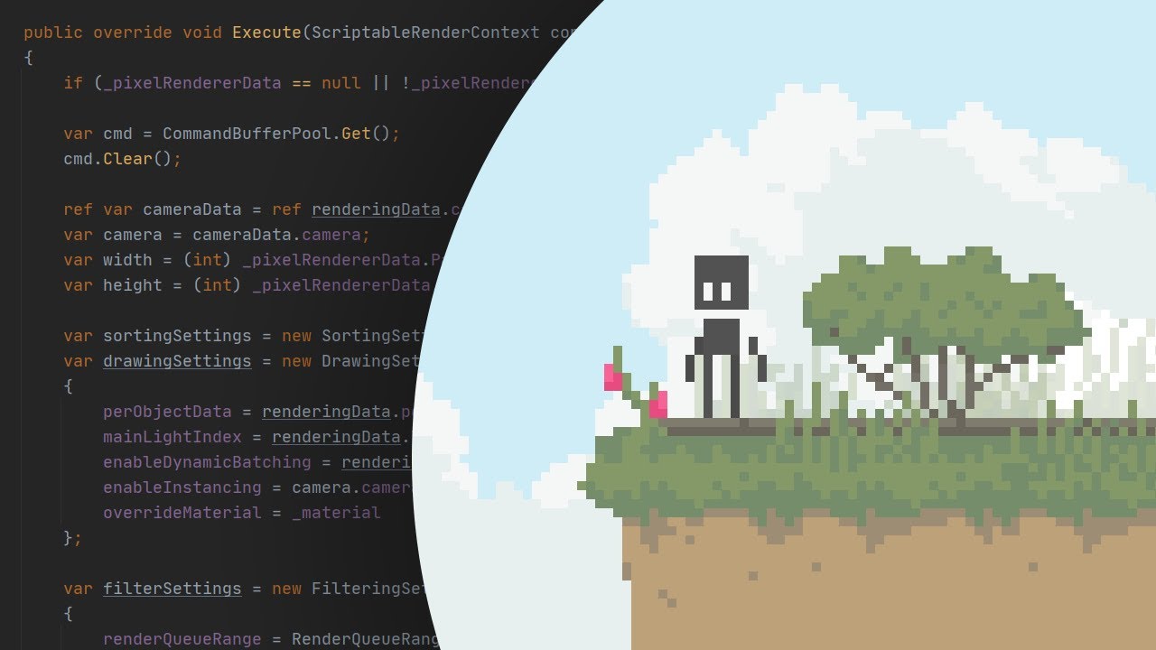
Check out the package:
https://github.com/aarthificial/pixelgraphics.git
Play the demo:
https://aarthificial.itch.io/pixelgraphics-demo
Source code:
https://github.com/aarthificial/pixelgraphics-demo
Consider supporting the channel on Patreon 🖤
https://patreon.com/aarthificial
Timestamps:
0:00 Intro
0:38 Package overview
2:06 Customization
3:...
this video shows and explains what I want to do but I cant figure out how to run his demo
There's a float that multiplies the strength of the effect, right?
yea I guess
I think it's the property feeding into the blend

I think the speed just multiplies the rate at which the grass moves, not how far
So it'll wiggle back and forth faster but not further
There was another float going into the blend node, can you try changing that in the material and see if it makes a better result?
the blend value u mean>?

what do u mean with further?
I put the BlendValue to 0 and now detachment is clear

this detached pixel wasnt there before
and btw these are different sprites
they are 16x16 tiles
Guys is it possible to write a projector shader to desaturate where alpha = 0?
on the source texture
Are you sure this is an issue with the shader and not the sprites just being misaligned?
yep
desaturate the black part instead of making it darker

cuz the grass is a different shader than the ground blocks, and the shader just makes the sprites "wiggle"
Can you try putting the ground material on the grass and seeing if it disappears?
so like on the trees it looks cool and nice cuz it makes everything wiggle, while on the grass it look bad cuz they become detached
ground material?
The material you use on the ground, that doesn't wiggle
its a sprite
Can you just put a normal sprite unlit shader on or something?
I dont know how to remove a shader without either breaking the shader or breaking my stuff
like I cant remove the material
You can always undo it after putting a different material on
Just make a new material, put on a sprite unlit shader with the texture you want, and put that on the grass
ok done
is there still a gap?
nope
hmm
After the blend node, could you put it into a saturate node then the texture node?
Might be some of the UVs going negative or something
math or adjustment?

Is the gap still there?
yep
f
Wdym?
Guys is it possible to write a projector shader to desaturate where alpha = 0?
on the source texture

like u see the bottom line is getting "masked out" but its in the voronoid and the UVs are still getting rendered good
after the blend node
or is there a way to increase the bottom black part?
to like troubleshoot it better
Maybe try skipping the voronoi entirely and just put the pixellated UVs into the sample texture node?

this wont animate it tho
just to see where the problem is


Ok maybe feed straight from UV to sample texture?
The split just takes one component, it doesn't alter any values
It might be the texture has a line of transparent pixels at the bottom, and offsetting very slightly would skip them?
fair enough
no gaps

Ok that's nice
idk
Maybe after the divide, add 0.01 and saturate? So have all the pixellation stuff, then at the end add a tiny offset, saturate, then put it into the texture sampler
seems good to me
No gap?
fair
how do I add a 0.01 ?
put an add node, and then type that into one of the inputs
the out where?

0.01 isnt doing much
So still a gap?
yep
im trying with different values
and I put the 0.01 to the Y value too
ok got it
I put a value of 0.0002 into the Y and now there s no gap
amazing :)
now just pretend that's your pixellated UV and use that throughout and it should hopefully work
fingers crossed
do I need the saturate?
Probably not, because the maximum value of the pixellated UV should be <1
mhh I mean its not really fixing the problem
Saturate basically clamps all the values between 0 and 1, it's good for being safe if a value might escape that (whether it's supposed to or just some numerical error) but in this case yeah it's probably not needed
the gap is still there I now can shift the sprites
i see
you can shift the sprites to remove the gap though right?
yep
but that s not really the fix I was going for, cuz like I could ve done that just by grabbing the sprites and position them a bit lower
did u check the vid I sent u earlier?
maybe that can help
this is part of his graph

as far as I can tell, multiply -> floor -> divide shouldn't put any pixels out of the 0-1 range that UVs live in
so i don't know why something should be going wrong there
it might be a numerical issue of some sort in which case a cheap fix is all it really warrants
cuz I just launched this guy's demo
but im getting the pink material error
idk, sorry
i'll have to sleep now but if you're still having trouble tomorrow i will be back
yea no probs
gn mate
and thanks for everything
Yeah true. But what when the object moves to negative quadrant? Then the world space cords would be 0 right?
negative quadrant ?
are there any free texture websites to download textures other than textures.com
You mean pbr textures or/and seamless ones?
Seamless textures
These were all valid ones: https://thegraphicassembly.com/best-websites-for-free-pbr-textures/
Thanks
I've written a simple shader in hlsl which I'm using inside of shadergraph (as shown in screenshot). But when I move the around (in the scene view, right now I can't test it in game), there's some weird clipping going on with the mesh. Why is this and how can I solve it?


Pretty sure it's because of Transparent surface type. Transparent objects don't render to the depth buffer (in order to achieve the correct alpha blending). But that also means it cannot sort per-pixel and only sorts based on the mesh origins and triangle/index order.
Should use Opaque instead. Unless you really need alpha blending... might then be able to do a prepass writing only to the depth (ColorMask 0, ZWrite On). But if you just need 0 or 1 alpha can use Opaque + Alpha Clipping instead.
i was using fog node in my shadergraph but the amount of fog is effected by the object direction towards camera
how can is fix this?
do i use some combination of world space of object space? im not sure which one
Thanks a lot, I didn't actually need a transparent surface, I just made it so 'cause I was trying to replicate a surface shader from SRP and those have alpha, so I thought 'Well, why not?'. Turns out it isn't that good to use transparent when you don't need it
I mean what when the worldspace values go negative ? -1 -2 -3 etc… won’t the calculations go off ?
Well no since both are in the same space. The calculations will go off if we dont translate thr normal map direction to world space.
So then I’ve messed up something while writing the Beckmanns distribution function or the spec function 🙄
As the object goes black when the world space cords are negative 🤣
I need help with a rendering bug here's a video
https://youtu.be/BXF5u5lQFTQ
any ideas on what's happening?
so when i come close it looks fine, but when i get further away, it distorts
What do I have to do to make this effect not get bigger or smaller based on distance from the object?


hm I got this far, the texture is futzed up but it does respect scale
how do I unfutz the texture though

Freebie: Object-stabilized screen-space UVs. Probably useful for VFX, I don't know! :D
With a hat tip to @Ed_dV who made the same thing for Unity, here's an @UnrealEngine version.
Material graph in the replies!
#realtimevfx #gamedev #gameart
Likes
855
Retweets
219
here is someone achieving it but I cant figure out how to translate UE4 to SG
Should be something like this
#archived-shaders message
👀 Sweet thanks, that looks to be exactly what I am shooting for. 👍
works perfectly 👍

hello, a shader of mine isn't being affected by a global light, anyone can help?
nvm fixed it
this is supposed to be the formula for a signed distance cube, but when I impliment it in shader graph, the result I get is eight points, the outer corners of a cube, and not the cube volume itself

right from the start, absolute has a completely opposite color to what theirs shows for some reason

this could bed an XY problem

im TRYING to do this
Beer-Lambert light light absorption through a transparent medium
this is as close as ive gotten and its obviously completely fuckin wrong

but im too inexperienced to know what im doing wrong, what, where, when why, or how to diagnose or do basically anything
That helped

yeah SDF is not the answer

even though i have the sdf of the cube, I cant use it to make this look because im too inexperienced
I want to create this printed mirror wall on the left

I made a mask on photoshop

but I don't know how to combine them in shaders, nor I can find any tutorial please help
Is it possible to toggle these at runtime?

Hi @kind juniper This is happening to us on Android phones and iOS phones, seems not to be just on some devices. In particular we think this native shader is the problem: ‘Particles/Standard Unlit’
Is there any other shader we can test that is similar to this? Many Thanks!!
There is anyway to debug this and get know what is the problem? im not sure if the platform is the problem this happen to us with iOS also.
Maybe try the mobile version of the particle shader.🤔
No clue. I've never encountered an error like that. Might want google a bit.
Hey @kind juniper
question
so
would there be a way to find out what shader I am using to get the right pipeline for it?
What file extension does it have?
..?
it says .shadergraph
Then what was the file that you took a screenshot of before?
the same thing
In general code
It was definitely a compiled shader, not a shader graph
ik
but
I looked up a solution and it says to use shader graph and it told me how to get it
that the material is pink
yea
hold on

there
that pink material isnt supposed to be pink
Okay, so yeah it is a shader graph. And it's not exactly compatible with Built in render pipeline. If you want to use it, you should switch to URP or HDRP
How do I get URP or HDRP
also what is better quality URP or HDRP
Would it be HDRP
High Definition Reder Pipeline
Yes. HDRP is for photorealistic stuff. It's also several times more complicated than urp.
so urp would be better for simple wise
Yep
how do I get URP
That you can Google. There are many steps. Can't explain everything here.
k
Any idea how to accomplish this effect:

instead of this:

My main problem is that i have no idea how to make objects have one unlit color and make them transparent at the same time.
Without parts of the mesh 'adding' to each others alpha
How to create transparent object with uniform color?
If you're only doing one trail or don't want them to overlay, you can use the scene color since it'll only include the background, not the trails, so it won't build up
(so lerp (scene color, trail color, alpha))
Thanks a lot for help. I don't know why i didn't think of that.
Any idea on how i could make this work with multiple trails
Late heads up to let you know that the shader was indeed faulty/incompatible. Top right of the master node, there is an exclamation mark icon.
The solution stays the same as dlich's, a render pipeline is required to use shader graph shaders.

Shader Graph does now have Built-in support in Unity 2021.2+, but may be a bit limited (Scene Color node might not work)
Hey anyone know of any good water/ocean shaders? I wanna make some really rough looking waves form on my avatar, I know mochi has a water shader but I'm looking for like hurricane type waves with froth and all with crescents if possible. Or something that is a really nice hurricane storm water shader so I get those really nice rough waves
I got this lava shader from an asset, how would I make it work properly on a sphere?

Like basically a sphere lava
It's not shader graph
Would need to se the shader to help i think
what's improper about it right now?
umm, nothing I just want a spherical version of it
Pastebin
Pastebin.com is the number one paste tool since 2002. Pastebin is a website where you can store text online for a set period of time.
I basically just want it to be a spherical lava ocean
What's not spherical about it now?
If you apply it to a sphere, does it not become spherical?
No it looks really buggy
Basically tries to be plane even though it's on a sphere
Sounds like it doesn't displace along the normals then
hi guys, I've been looking for this info for a while now :
How do you make UI SHADERS in unity 2021+ ?
ours have been working well on 2019, and while doing an update, they all broke
from what I understood, it was an error and it won't be fixed
but I guess the community have found workarounds of some sort
can you help me with it
Im kinda bussy so i cant do much rn
All you would need to do is change line 71
And maybe get the normals i didn't check if they where already in there or not
this is how it looks rn

I'll send you the code
can you maybe help me with removing those weird gaps?
they seem to be there because of the edges of all of these "sides", there are 6 sides here that are not connected with each other
because the height of the edges of all of them is different, the texture seems to be properly flowing though

that's it
I think thats because it sets the ner vert pos instead of adjusting it. So you want to do += instead of =
And if you didn't fix it already, it needs to move in the normal direction
Yes I'm doing vert.vertex.xyz += normalize(vert.vertex.xyz) * lerp(_MinHeight, _MaxHeight, texPixel.r) * _Amplitude;
what do you mean
that doesn't change anything
Well the other thing I can think of is that you are sampling the texture using the second uv chanell
Does your sphere have proper uvs there ?
it's the built in unity sphere
sorry I don't really know much about shaders 😅
this is from an asset
what do you mean by sampling the texture?
Built in sphere has weird uv mapping. Try importing a sphere from blender and using that.
tex2Dlod(_HeightMap, vert.texcoord1 + _FlowDirection * fmod(_Time.y, 1200) * _Speed); is sampling the height map in the vertex function
this is the blender sphere...for some reason

is there something I can fix?
The displacement is too strong. Try reducing the multiplier.
Seems like the displacement is toi strong yeah
noun
1.
the action of moving something from its place or position.
"vertical displacement of the shoreline"
I meant in the term for shaders lol
In this case it's the displacement of the vertices
I was playing around with the amplitude and it kinda makes sense now
it has this now, which I guess can be ignored but it keeps getting bigger if I increase amplitude

I guess it's due to the way the sphere vertices are placed. Can you enable wireframe mode in the scene view and take a screenshot?


Yeah, that makes sense. I think you wouldn't be able to get better results by sampling a texture for the heights.
You can't really map a rectangle to a sphere without any artefacts.
If you want procedural planets or something like that, I suggest checking Sebastian Lague's series on procedural planets. He managed to solve the issue somehow.
Oh
wasn't making procedural stuff but thanks I'll check that out
thanks a lot for helping out with this, I really appreciate it!
You could use triplanar sampling to have it go on any smooth surface without artefacts
How does that work
Never really used that before
you render that texture with 3 different UVs, the u and the v are set to the pixel's xy, yz, xz object/world positions, then, you combine them all this way -> get the pixel's normal, make it... ehh.. not normal? put it into an equation to make x + y + z = 1, after that you add everything together: nX*texYZ+nY*texXZ+nZ*texXY
A Unity Advanced Rendering rendering tutorial about triplanar texture mapping.
surely it's explained better here xD
I've never even made a shader myself tbh 😅
This one that I'm modifying is from an asset
you just need to modify the existing one
find the part that takes in the UVs and start from there by switching them out to object or world positions
could you help me a little with it?
I'm on my phone, so unfortunarely not right now
hey, im unsure which channel to ask this but here is my problem
my armor looks very dull
is there is a way to make it look better?
or adding albedo texture is the only way?
thanks


how can i convert uv to position on the mesh
I need to change texture on mesh based on some things from scene
How can I add URP Decal Projector support for my custom shaders?

can someone please list off the full versions of the image abbreviations?
prm_B
prm_G
prm_R
prm_Alpha
_cdr
I'm using the built in rendering pipeline to write a custom shader based off of this tweet. I'm stuck on the part where it says "Get length or sqrMagnitude of that (dot with itself)". Basically I think it's saying that I should get the dot product of a world position fragment, but wouldn't that just be 1 since the vectors would be identical??
this is the tweet:
https://twitter.com/Ed_dV/status/1321618279270473730?s=20&t=XVQB3h5doKLvlvlKVyjdbg

(2/2)
Files are available on my patreon if anybody wants to play with them or use them in your projects. See what's available at https://t.co/XsxxAIDuxW
Likes
119
then what colors do I put into the metallic, or smoothness maps?
Colors ? Metallic and smoothness maps are greyscale
Normal textures.
I am having some trouble with multiple UV channels.
Im trying to export multiple UV channels but I can't seem to find the other UV channels/map layouts

when I set anything at that UV3, its always the same layout as UV0
the mesh im exporting from 3dsmax definitely has different UV layouts in channel 3 (4) but for some reason when I bring it into unity, it doesnt
what are the steps to figuring out what is going wrong? Im guessing its something to do with the export of the mesh from 3dsmax
They show you the graph.
But since you're in BiRP, you know about the length keyword, yes?
I think what they're actually saying is that since the sqrt of the dot product of a vector with itself is the length...or another way to say that is that the dot product of a vector with itself is the squared magnitude....
You can either do sqrt(dot(v,v)) to get the length...which is the same as length(v), or just do dot(v,v) to get the squared length.
hmm, exporting as FBX instead of OBJ retained the extra UV channels, but now the extra UV channels wont show up in scene, they work in the preview though (text textures)


Unity Forum
I need to create a shader that has 3 UV sets total to use in my URP project. The 3 UV channels would be for texture 1, texture 2, and lightmap. I dont...
I cant find this in shadergraph
That's from blender.
In SG, just select the UV channel (UV0, UV1, UV2, UV3).
Ah that explains why I couldnt find it.
Is there a special way to combine UV channels in SG? per the picture above, the preview shows the two different texture channels working together, but in the actual mesh its taking the texture on UV3 and projecting it as if it was on UV0
IDK on that, but you'll probably have to show others your graph.

here is my graph which is just a copy of that guy's graph from that post - the preview its working
hm wait mayvbe I am dumb
it might not be the same mesh in the scene
okay it wasnt the right mesh in the scene - but this was my worry about using an FBX - the model export is completely wrong

I was using OBJs because they're simple and just work, but OBJ wouldnt export multiple UV channels
FBX supports multiple but it also brings in all kinds of useless bloat and settings and multiudes of ways to fuck up the mesh
that tiny cube is allegedly the same mesh 🤔
Also note that your x value is a hard-coded 1 in your blend.
But others will have to comment on this, as I'm spaghettied out for today. 😉
i guess this is an export settings problem now rather than shader
yeah I havent even started on making the blend 'correct' yet, I am still stuck just trying to get it to show up on the mesh
woohoo fixed the FBX, multiple uv channels working as expected

unity was converting units but Im already working at unity's scale in 3dsmax

anyone have a starting point i can use for a pixelated 2d fog my attemps have been underwhelming
or overengineered i should say
i think this is the bare minimum needed but theres a lot wrong (fog doesnt move only one direction for starters)

that makes sense, so then i think I'm doing that step correctly. the issue now is that for some reason the length is always 1, so then it doesn't make sense to be subtracting it with 1... maybe the way im getting the "world position from depth" part wrong.
I have a question that I have no idea how to properly explain, but I'll try. I have a position node that passes Absolute World Position (X, Z) into a Sample Texture 2D LOD node's UV input. Let's say for example the world position of the vertex is (5, 0, 5), how does the shader decide what part of the Texture to sample from? It's doing what I want, I just don't understand how it works.

Depending on how the texture/sampler is set up, it will either clamp or wrap (most common is wrap) the UV's around and around until they are in the 0 to 1 range. So in your example xz of 5's wrap around several times to end up being a (1, 1).
This is why the tiling and offset nodes multiply for tiling, and add for offsets. If you do the math, you'll see how it works accounting for wrapping.
But if you clamp, you clamp all results to 0 thru 1. Then there's some other weird stuff like mirror I won't bother with.
thanks, thats really helpful
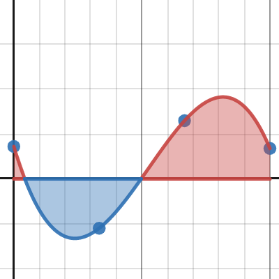
What are some different ways to rescale(?) transform(?) a linear range of values into a curved range of values?

math is not my strong suit 😨
isn't there like an animation curve node?
shit, is there? 👀
I think so
remembering highschool math, power node multiplies things by themselves x numbers of times 🤔 might be what I need
well yeah you could use pow node or mul to create like an x^2
You could also go to https://easings.net/ and see the math formula behind any of those curves
animation curve would be way easier to get the exact ranges I wanted though
Oh that helps
for example:
https://easings.net/#easeOutCubic
function easeOutCubic(x: number): number {
    return 1 - pow(1 - x, 3);
}```there's javascript code for that curve
which you could adapt to shadergraph
Wow this site is really handy, the preview buttons are awesome
yeah i love it
Thanks for the link 
why doesnt my custom shader function have any input/output dots?

maybe something just buggy with the node, created a new node and no issues..
You may have clicked the arrow in the top right of the node (when hovering over it). That hides any unused connections.
Hello, how would I go about getting the distance from an object with my outline shader and the camera? Cause I want my object outline to decrease in scale as I get firther away
URP + shaderlab not graphs btw
https://www.desmos.com/calculator/omcjqjxroq this rescales the 0-1 range to a curve

Desmos
might be useful
Also you could look into Lagrange polynomials, such as https://www.desmos.com/calculator/gcfrl9lozq where 4 evenly spaced values (say, in a float4/Vector4) are converted into a smooth polynomial interpolating them
Desmos
https://gfycat.com/klutzyunitedaustraliankestrel
What could I use to offset my UVs so that when the sphere is rotated, it looks like its inside out when its really right side in?
When the sphere is actually inside out, the texture moves opposite to the rotation of the object, so I'm thinking the answer is that I need to offset the UVs by twice as much as its rotating in the opposite direction of its rotation

But how to actually do that 🤔 I am not sure how to get the object's rotational value, or where to then add/subtract/divide/multiply/ what method to then translate the UVs
View Direction sorta does it but at a scale way beyond what I want 🤔
hmm the cross product of the tangent view direction vs the object view directionalmost kinda does it, but only on one axis, the other axsies get weird

I cant seem to isolate whatever is happening that makes it work on that one axis and then apply that to the other axis 🤔
this -almost- works but there must be a simpler less stupid way, the scale is way off on the result

there's too many small weird things to correct for, this cant be the answer, gunna restart from scratch 🤔
How do I move the normal vector in opposite direction? 🤔
I feel like the answer is just going to be braindead simple
Why don't you simply use an inside-out sphere mesh ?
That's less fun than solving this
I could but I want to see if I can do it without using an inside out sphere, mainly because I can't also use URP's lighting on the outside
and I don't want to layer two transparent spheres
Hey so I'm trying to plan out script and shader I want to set up, that will allow me to adjust the contrast value of individual tilemap layers.
So far, the only thing that works in my head is to have a camera outputting to render texture for each layer, then run each of those textures through a shader material that can adjust the contrast (haven't gotten to the bridge of how to do this yet)
but this seems a bit messy... +1 camera and material for every layer
Any one have any thoughts on better ways to do this?
I've barely touched tilemaps, but if you assign a material to the tilemap and there is a way in the shader to differentiate the layers (maybe zcoord ?), you can do what you've said with a single shader/material.
@tight phoenix For the normal, logically the normal of the inside but opposing side of the sphere has the same value, so you shouldn't need to touch it 🤔
I'm not sure what that means, but if I turn the mesh inside out, the specular highlight wont be at the surface anymore, itll be at the inside out surface
Unity is the ultimate game development platform. Use Unity to build high-quality 3D and 2D games, deploy them across mobile, desktop, VR/AR, consoles or the Web, and connect with loyal and enthusiastic players and customers.
Ah, erm yeah, sorry, my point was only for if looking trhough the exact center of the sphere
Ahh
I think all I need to do is move the normal vector by twice the object's rotation, this person here discusses how to get the rotation value of the object in the graph, maybe I can make progress here
time to learn matrix math
Have fun 😄
why doesnt this work? 🤔
if I take the real value, make it opposite, and add twice the opposite, shouldnt that make it rotate in the opposite direction?

obviously I am wrong, but I don't know where I am wrong in my assumptions to make it produce the result I desire
hmm the problem must be because im not sampling the object's rotation value
back to matrix math I guess
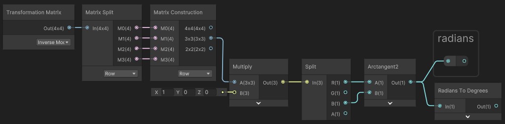
this sollutin only works in the Y axis, what do I have to change to make it work in all 3 axis?
no matter what values I plug in where, it just wont spin backwards
trying to rotate by the radians of the object didnt work

I can change which side the normal vector ends up on, but cant seem to make it rotate opposite
this should be stupidly easy
its literally just 'take whatever its doing, and do twice of it the other way'
why cant I figure it out? am I too stupid?
thjats what I was thinking too. I'm already using z-coord for parallaxing,so I might not want to use that value, instead just use a slider within the shader itself to have direct control over the variable.
but I think thats possible
but the thing is, i'd still need a camera and render texture per layer, because if I just try ot grab all the layers into one render texture, then its just all one flat image
if I could somehow get one camera to output 4 different render textures, that'd be nice
but maybe I should just concede to having the extra cameras
at least, get it working first
Is there a certain order in which image effect shaders process texels (or chunks of texels, really) when you use Graphics.Blit?
Like, should I expect the shader to affect the top-left region of a texture first, or something like that?
Is there a way to mix raytracing shaders and compute shaders in such a way such that I can use compute shaders for the shading but use raytracing shaders for ray-scene intersection?
Add position and normalized view direction dot surface normal multiplied by normalized view direction.
That gives the position on the other side of the sphere
(if it's radius 1/2 which the default unity sphere is)
Ill try this, one mo to set that up
Which space should each of those inputs be in?

Probably object space would work best (should make it independent of scaling)
Also you're adding and multiplying in the wrong order
oh I guess I forgot my pemdas or pedmas or whatever the acronyms is
probably should've used brackets tbf
Position + (View Direction * dot(View Direction, normal))
I'm definitely still making a mistake 🤔

is tangent space normal vector not the normal maybe?
Now im not sure what space/direction/thingy node represents surface normal
I thought it was tangent but now im doubting
Object space normal vector
Object space everything
Tangent space normal vector is just (0,0,1) by definition
Oh
(unless you use a normal map)
Object space everything isn't producing the correct result
its spinning twice as fast in the direction that I turn it, instead of spinning equally fast in the counter direction
something must be flipped
Hmm that is producing even stranger results

the effect is getting close to existing, I think its just a value is backwards or negative when it should be positive somewhere
No subtract top from bottom I mean
Subtract the view direction stuff from the position

Yes

this is the product of the current graph
minus the turning salmon part that's the gif's issue
up/down doesnt seem to change at all 🤔
while the others are rotating
I think the display sphere in shader graph is radius 1
But the default unity sphere is radius 0.5
So double the view direction stuff and it should work for the display sphere?
oh you are right it works in scene
ayy nice
that's weird that they aren't the same thing
Yeah I forget why i found that out, but it was probably screwing something up
Ig for scene view it could reasonably be used in game, whereas here it won't, so they can do an analytic sphere rather than a mesh
works great, added multiplying as a material param so it can scale arbitrarily

bigger on the inside 👀
If you're just using it on a unity default sphere and do everything in object space I think it would be fine with scaling
Or any sphere that's diameter 1 by default
(the scaling affects the world space stuff but not object space)
hmm yeah when I zoom in and out the effect is getting scaled
hmm or maybe its not, might be my imagination
ill use it as UVs instead of as a color, should reveal
okay yeah it was my imagination, everything works great 👍
trying to access the normals in _CameraDepthNormalsTexture by using DecodeDepthNormal() but for some reason the output normals are all solid black.
I was working so hard to get this working that now that its working I have no idea what problem I intended to solve by using it
or even HOW to use it to solve any kind of problem at all
Ig since you can get the back of the sphere as a function of properties of the front, you can more easily do refraction inside the sphere or go through some volumetric thing
I finally remembered what I was trying to do - get that colored glass look where the highlight is bright on the surface, but the color is very dark near the highlight, and brightly bottom/backlit


I don't know why I thought rotation based on normal vector would do literally anything to help me achieve this
this looks roughly right but this is just the exterior - I need to somehow also get the interior

which I knew i needed that reverse invert mapping 🤔
left is how it should look, right is how it does look (photoshop)

ill keep plugging away at it, I have the inside out UVs now 🤔
My point was to apply the shader directly to the tilemap, not to a rt containing the rendering of the tilemap
