#archived-shaders
1 messages · Page 1 of 1 (latest)
so you could generate a grid of spheres by performing the same check that you'd perform for one sphere, but by shifting the coordinates so that you're always looking within a small square around the origin
You have to use CanvasRenderer.SetMesh to turn your mesh into a UI thing, then it just works with sorting like any UI element
https://i.imgur.com/qt50AF1.mp4
Woah WHAT
Okay that's huge, how did you do that?

I managed to do this yesterday but I had to abuse the particle system
wait its not showing up in game, only editor 
Is your mesh on the right layer?
https://github.com/mob-sakai/ParticleEffectForUGUI is also a good package for particle effects in UGUI
It might be the shader , I just slapped my normal VFX shader on it, not a UI shader
the mesh itself is working at least
The shader is the issue tbh
I'm converting it, hang on
I also find that it has trouble sorting against RawImages
My bf is a raw image because it's using a render texture
This will massively improve my workflow if this works
its working now
I will DM, I want to write a tutorial on this now haha
here in this code the UV is passed to fragment function before displacement, and then x,y,z displacement takes place distorting the UV. Now any texture inside frag function using this UVs will be distorted depending on the displacement. How do I achieve this in shader-graph? If I use world UVs the texture stay the same after the displacement, like a projection from top, I want the distortions.

I think you can do that with a custom interpolator
Add Block node > Custom Interpolator

Yep, should work
interesting so how does that work? I am learning about this first time.
right click on the vertex block to get that option
then you can just connect the world UV to that new connection
and use it like any other node


oh wow. That is super cool. Thank you! trying now
made just for moving data from vertex to fragment
yeah I dont think theres much info about this very useful feature out there
found it by chance by right-clicking the vertex block :/
@neat hamlet you saved my life!!! it fixed my problem!!
glad it works!
thank you very much... I was trying to port an ocean shader from Built-in RP to HDRP using shader graphs and I couldn't solve this issue.
no problem 😄
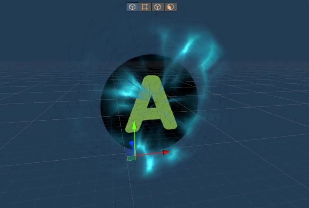
Hmm so I'm looking to create an effect where I have an invisible cylinder or so that expands outwards from a position and all walls inside the cylinder just stop showing up..
My idea was "oh okay, I'll just take the vertex position, see if thats in the cylinder and if so, will add like 300 to the Y axis to hide it"
Issue with that is that my walls are pretty simplistic (just cubes) at the moment, so they only have vertices at the ends, so I don't think that works, plus I'd want it to not be limited to vertex density.
But I can't really think of what else to do.. I guess I could hide it with alpha if I make the shader transparent instead of opaque, but that seems to have so many downsides.. so not sure
You could keep the shader opaque but use alpha clipping. Discards pixels if their alpha is below a threshold.
Can also use dithering with that if you need to fake some transparency
Hmm that works pretty well actually @ alpha clipping, just gotta see how I'll make the clipped off parts black instead of seehtrough
If its good enough for Elden ring its good enough for anyone haha
Could render both front and back faces. Make back faces black (using Is Front Face -> Branch if in Shader Graph. Otherwise look into VFACE / SV_IsFrontFace)
Not sure if that would look weird if it's still lit though. Could likely edit normals too, to point into cylinder center. (Or all in the same direction to at least make it a solid colour)
Or use multipass / two separate materials
hmm yeah does look a bit odd with just changing backface colours. Will have to try around~ Thanks
Hello is there anyone who can help me a little with making slime/jelly shader in unity urp ?
You could start by describing the specific kind of effect you want
That would be a start to finding suitable guides or resources
My goal is to make shader that make material little transparent and kinda like jelly. I tried with glass one and different normals but its still doesnt look like jelly. There is few tutorial on youtube but they dont work on Urp unity. And im not sure what to do ( trying shader or shadergraph) also someone mention subsurface scattering but well there isn't a lot of information about it. I'm graphic designer and kinda newbie to unity, so I dont understand creating shaders yet. Thanks for any advice or help
There isn't a lot more to it than that
There's tutorials for glasslike refraction and subsurface scattering
Personally I'd use custom reflections with authored cubemaps or matcaps for an exaggerated cartoony effect
But beyond that it's just tuning and artistry to get it looking good
So there also no solution to turn this shader https://youtu.be/LEfnQX9acgc into one working in urp ?

This video was inspired by one Reddit user. For me, this is the first big montage in the last couple of years ... I have a little lost the skill of shooting and editing, forgive me if the moments are not clear ...
Video diary dedicated to the game:
https://vk.com/golfkeeper
https://twitter.com/golf_keeper
Also sources from the video (shader, ...
Not directly, but there are refraction shaders for URP and it's not too complex to make your own
@grizzled bolt okay I will try then. Thanks a lot for help
I have a structuredbuffer of a set of objects I need to do computations on per-pixel. A certain computed value will differ per-object depending on a "type" I assign to them. Would it be especially costly to represent this type as an integer and use a switch statement to differentiate between object types, or should I have a separate buffer for each kind of object?
Yes, unless there's a poo-load of math. But it may not make much practical difference because the GPU uses a technique for latency hiding of texture reads. So if using a texture is a lot easier for you, I'd try it and see if it is "fast enough".
"or should I have a separate buffer for each kind of object?"
What?
Hell, you could have a separate material/shader "for each type of object" if you want to, as far as I can tell from your post.
So really, we need more detail.
How many "types" are there?
How many different calcs are there per type?
How "bad" is it if there's 15 types and you have to do different calcs for each type? Well, the worst case is divergence to such a degree that you execute all 15 possibilities for each pixel per frame. How bad is that? We cannot tell.
When I was saying "objects" I didn't mean for it to be conflated with "GameObjects." As I said, the computations are run per-object, per-pixel. If you're really curious about what I'm doing, I'm writing a raymarcher, and need distance data for each object. The number of calculations per-object varies, but this possible switch statement is likely to be run multiple times per object, which is why I'm concerned about performance.
It's likely there will be roughly 10 different object types, although I can't be sure what all I'll add, and so there may be even more.
That's really why I'm concerned about performance, since, as I understand it, passing computebuffers to a shader can take quite a bit of time
and, I'm still not 100% sure what's okay and what's not when it comes to branching in shaders using Unity's shader compiler. So that's why I'm asking about which approach I should use here.
okay new question
why does this cause no errors,
            {
                float3 pos = mul(float4(position, 0.0), r.inverseTransform);
                return length(pos);
}```but this causes a D3D11 error?
            {
                float3 pos = mul(float4(position, 0.0), r.inverseTransform);
                return 1.0 - length(pos);
}```anyone know how I can fix shaders? My friend sent me a shader to use but for me it doesn't take in lighting data

it also doesn't change its look based on the fog and how far away you are from it
here it is, top image is far away


keep in mind i'm extremely new to shaders and have no idea how to program them so i have no idea what i can do ¯_(ツ)_/¯
judging from your fragment shader above, you dont need to add vertex shader in you surfaceshader. the worldpos position is calculated internally by surface shader
hey @tight phoenix is this along the lines of what you wanted: https://www.shadertoy.com/view/NdGBzK

Yes very 👀
wonderful
the front face is given to you for free by unity so that's good, in my shader I calculate the refracted ray using Snell's law, I reorder the spheres by distance, check if a ray hits any of them and calculate the normal (the method used here isn't 100% accurate but it's good enough), if it does hit a sphere, I just pretend it's lit from the outside (I'm assuming the light won't look too different if it's refracted properly vs not) and then go through some rough specular/diffuse reflection. If it doesn't hit a sphere, it finds the location and normal where it hits the edge of the cube (I calculate the distance to each of the planes, sort them, then get the one corresponding to exiting the cube); if it's too low an angle, it reflects it and repeats to find where it exits (it might be possible for 2 reflections but I only consider one). Then it calculates the exiting refracted ray, and where that lands in the environment
Feel free to ask any questions ofc!
anyone know how i can fix this? i've been struggling with it for about 2 days now
Think about it in terms of divergence of parallel threads.
So if you have a ray you're marching in each of, say, 64 threads at once (each one would be processing a pixel) and the rays hit different object types, you have divergence.
What you have to consider is that all 64 "cores" are running in lockstep sharing the same instruction/program counter. So when there's divergence, some cores are masked off, others are active if they're inside a condition that applies to them, but in reality each applicable condition is executed time-wise for every one of the 64 cores because they share a program counter.
So you incur the cost of all applicable conditions being executed, even if some results are ignored due to a core being masked off. If ALL cores don't apply to the condition (they would all be masked off) AFAIK modern GPUs will skip over that condition by simply incrementing the program counter past it, or perhaps executing a series of fast no-ops to advance the PC rather than more expensive instructions.
There's no way for us to tell. Perhaps you should share your shader. Pastebin or some such is your best bet for posting it, IMO. Unless it is a graph. Also it would help to know what pipleline you're using.
i'm currently using standard
And yea i can share it through pastebin if you want me to
here ya go https://pastebin.com/rRyKbnNz
Pastebin
Pastebin.com is the number one paste tool since 2002. Pastebin is a website where you can store text online for a set period of time.
gotcha, so it sounds like I should just use buffers. ty
anyways, does anyone know a solution for this? i'm genuinely dumbfounded
for context, RenderObject is a struct I made, and its inverseTransform is a float4x4
Holy crap, no idea. And not going to even try to decipher that. Sorry. Maybe someone else will take a shot.
But you do have to make sure you've initialized everything properly, including shader globals. Some of that looks like it might be a shader reverse engineering, with all those "temp" variable names.
no worries, and yea its just really bothersome since i need the shader to have lighting but it just wont work
And i think i've initialized everything but i could be wrong 🤔 i don't know anything about shaders
What's the error?
"Failed to present D3D11 swapchain due to device reset/removed. This error can happen if you draw or dispatch very expensive workloads to the GPU..." etc

lol
What is it with these supposed compiler bugs lately?
IDK, maybe try making an interim variable. If I read it right, your only diff is the expression in the return statement.
So make
return result;```
Otherwise maybe you're getting some kind of NAN or NULL.Or returning the new result (which is different) is causing an infinite loop later.
Yep, tried making an interim variable. Didn't work.
I'm gonna try to see if I'm getting nan
But regardless it should cause a different exception, and it should do so regardless of if I try to perform arithmetic on its length or not, right??
The error only indicates a timeout. It isn't telling WHERE it times out.
You've caused that function to return a different result, and that could have an effect later on in program execution. Like some loop that you're checking for >= 0 but you've returned a negative value now if len is > 1.0 since you're doing 1.0 - len.
oh my god 🤦♀️ you're right
i had an if statement which would break a while loop, but i accidentally typed it just after the while loop's brackets
lol.
BTW, I occasionally do a magic show at midnight, it includes a psychic trick. 😉 (not really)
what?
I meant I "made a good guess". 🙂
ohh hahahaha
idk if this is a shader problem but yeah this looked diferent

now it looks way too red ?
it was metallic before
Another thing to do is index the object type into a material buffer. So you don't do if's or switch/case at all. But somehow you have to know the object's material index. IDK if this applies to your use-case at all.
But if you have 10 different materials/settings, you "just" have a buffer with various values you use in your calcs, one entry for each "type". Then it is indexing.
That is still divergent in terms of memory access, but what can you do?
IDK if you're actually ray-tracing an image or doing something else with your ray marcher, but have you seen this?
http://three-eyed-games.com/2018/05/03/gpu-ray-tracing-in-unity-part-1/
Unfortunately, the big issue isn't materials, although I never thought of approaching the materials in that manner, so thanks!
With ray marching, your objects are all primitive shapes (cube, sphere, torus, cone, etc.) and have unique signed distance fields. I need to differentiate between different objects so I can calculate the right distance for each object. Without separating each type of object into its own buffer, it seems like I'll either have to use branching or will just end up calculating the SDF of all object types for each object, and varying between them via the object's "type index" so as to avoid branching.
Word to the wise: Download HLSL tools for visual studio yall. If you have questions on how, it's really easy. And very helpful for anyone who does shaders in code
Hey, I can't figure out how to use the Parallax Occlusion Mapping node. What is the Heightmap Sampler? (Shader Graph)
Yeah, the SDF primitives will diverge across threads of each pixel's rays.
How are you searching these buffers? For-loop?
I feel like this should be fairly easy, but I cannot seem to get it to work.
I have a refraction shader and I want to remove the effect on the edge of the object it is on. This way you should not be able to see the edges of the object refracting
How can I best approach this? Already tried with distance, but could not get it working properly
Here is my setup. I am guessing I should get the noise generation output and make that fade in a way before adding it together with the refraction index?

If possible I want the shader to be able to be on any 3d object without issue, but this might be hard. Reducing it to planes only would also work, but less preferable of course
" and I want to remove the effect on the edge of the object it is on."
Clarify? What is an "edge" to you? The physical object's edges regardless of visual orientation, or is it the visual edge as if we're talking about an outline in view space?
From your graph I'm guessing it's an outline type of thing.
Right no you can clearly see the edge of objects, because the refraction changes (extreme form in screenshot). I want to reduce the refraction amount at the outline of the object

Just a wild guess, but you might be able to use a fresnel effect to scale the refraction amount, or maybe just the absolute value of the dot product of the view angle relative to the surface normal.
Does fresnel also apply to planes?
Well, yeah, but it's the same across it I think, since the view direction and the surface normal are always the same at every point.
You said you tried distance.... so I'd assume that was a distance to object-center. But you'd have to calc that distance in view-space for it to do what you're asking.
And then you'd still have varying amounts of distance for irregular shapes.
Thanks!
I will play with it a bit more.
How could I best combine the value of the fresnel or whatever I end up using with the noise output btw? I did not get this to work properly before as well
I was thinking it would scale it (multiply). So a value near-zero would have no refraction, and near-one (or higher) would give you your max.
I want to achieve this type of translucency in water. It is a custom shader code made on URP. How do I get similar results on HDRP? The default SSS material not working as it is just a one sided plane.

If I use diffuse color I am getting this shadows.

I can get kinda similar results with emission color but it will change depending on exposure and will glow at night.

Best option would be to use the color as unlit material and then only add the reflection on top as addition or screen blend mode, is there any option like that? I want to achieve it in shader graph as HLSL coding for HDRP is a bit complicated for me.
Yep, fresnel works perfect on spheres and capsules!
I'll look at another shader for the plane to get that to work properly
Do the specular and diffuse separately and for the diffuse part, lerp between the actual normal and a vector pointing straight up
@karmic hatch yes but how do I do that separately?
Make the material unlit, then the specular brightness is some function of dot(reflect(view direction, normal), sun direction)*saturate(dot(sun direction, normal)) and diffuse brightness is saturate(dot(sun direction, normal))
and plug in the actual surface normal for the specular part, and lerp(surface normal, up, 0.8) or something for the diffuse normal
and for the sky reflection and other reflections? Also I cant use normal maps in unlit.
okk got it
The sky reflection would just go into the specular part; you get out a vector that tells you where the reflected ray goes, so just find out what the brightness is there
Oh I forgot to mention but multiply the specular by some fresnel so it's stronger at lower angles
Well, that's what I plan to do
have been working on some other details before approaching the SDF types
Depending on how many we're talking about, you may wish to research "BVH GPU Acceleration Structures". It depends, if the SDF hit calc for each SDF is simple enough, and there's few enough there's too much overhead for the BVH tree to benefit you much. Because you still have to to a "hit" check on the bounding volume for each node in the tree. But it can often reduce the # of items you have to search to log(n).
And there's overhead for building that tree, but you might be able to do that only once per scene, unless things move.
Is it OKay to use code that I don't entirely understand in my projects?
In this case I've found a video that explains how to create water like ripples in a object surface that might be useful for me the future.
Thing is I haven't even seriously started working with rendering methods I barely understand the difference between CPU and GPU rendering, So I fear I could start a project that down the road needs to be altered to fit the project, but lack the knowledge to make it work.
Say I have a perfectly black and white texture, is there any cheap way extend the white / black portion of it?

Like making the The circle more like and eggs shape?
nah like expanding the circle
Could run a jump flood algorithm on it, e.g. https://bgolus.medium.com/the-quest-for-very-wide-outlines-ba82ed442cd9
But the cheapest method by far would be to use a distance field texture instead - or if it's always a circle like this, generate it with math, distance(fragmentPos, center). Can do some other shapes too. https://iquilezles.org/articles/distfunctions2d/
Can then step() at different values.
Provided that code has an appropriate license for usage, it's okay to use. But if you are worried that it might need to be altered you should try to learn what it's doing.
It's part of a youtube tutorial someone posted.
Others alreayd told me to try to learn what's happening in it
Hey, I'm trying to alter this CustomRenderTextureUpdate shader from ASE to be a a standard shader with alpha? Never written any shadercode before:
Idk if this is helpful but you can just use shader graphs instead of worrying about any actual coding
I dont think shader graph has an option for a customrendertexture shader
at least, in BIRP you need to add a .cginc file
yeah I'm new to this idk what I'm talking about lol
oh I read it the other way around :V its from custom render texture to a normal one
I think they meant to post code there anyway so I don't know how to help
Hi all -- I'm digging into some research right now about aperiodic texturing that could be performant on mobile for triplanar texturing. I started to look at wang tiles but I was curious if anyone had found a solid technique for breaking up tiling w/ a single tap.
Here's the GPU gems article for wang tiles. I feel like its up my alley but not clear on how to make the lookup texture for the pattern.
It also seems pretty complicated to author textures. There's an article written by a Path of Exile dev about how they used it: https://web.archive.org/web/20180311011512/https://www.pathofexile.com/forum/view-thread/55091
NVIDIA Developer
Chapter 12. Tile-Based Texture Mapping Li-Yi Wei NVIDIA Corporation Many graphics applications such as games and simulations frequently use large textures for walls, floors, or terrain. There are several issues with large textures. First, they can consume significant storage, in either disk space, system memory, or graphics memory. Second, they ...

Path of Exile
Path of Exile is a free online-only action RPG under development by Grinding Gear Games in New Zealand.
Has anyone been able to find an approach that's worked well for them? This is the most promising lead I've found so far. Seems like a lot of terrain shaders like Microsplat go for the extra samples to blend textures -- ideally I would only sample once for performance reasons.
I'm also kinda curious if something simpler like a truchet pattern would work? And if anyone has entertained the idea in the past.
@meager pelicanThis is how I did the plane and cubes. Works perfect on planes and good enough on cubes

if you multiply by 16 it goes to 1 in the center
There's some history of using Stochastic texturing to break up patterns, but IDK if that fits your use-case. As far as "single tap" that would be rough for most any technique AFAIK, maybe some random algorithm based on world-space could generate proper lookups, but I don't know of any. And triplanar has 3 lookups already, Maybe you can substitute stochastic for triplanar somehow, or merge them somehow so you're only left with the three triplanar lookups you already need. My head hurts just talking about this. But here's an interesting (old, and dead) thread:
https://forum.unity.com/threads/procedural-stochastic-texturing-prototype.628522/
And original blog link:
https://blog.unity.com/technology/procedural-stochastic-texturing-in-unity
IDK if that helps any. Good luck to you.

Unity Forum
This is the feedback thread for our research prototype implementing Procedural Stochastic Texturing. Use this space to ask questions, offer feedback...

does anyone know if there's something similar in unity to the unreal engine DistanceToNearestSurface node?
Not that I know of. That's an entire process, not just a node. The material-shaders/engine has to generate a distance field texture for the entire scene (well the opaques) as every object is drawn for maybe from the depth buffer, and that node "just" samples that field around some point passed in.
So if you want to make all your shaders write out a distance field texture somehow (MRT or separate passes and perhaps a custom pipeline), you could then create a custom node in SG to sample that texture. I don't do UE, so the specifics as to how the distance field is represented are unknown to me, but are probably not all that complicated otherwise it would be very expensive to do at all.
You might be able to fake it by using a world-space calc from the depth buffer, and running a full-screen pass to find the nearest point to some world-space point parameter. But wow. And it won't be 100% correct, due to using a depth buffer which doesn't know about pixels "behind" the nearest one.
Hello, I am trying to follow a tutorial for creating a Cell Shader however I run into a few issues. Within my lighting.hlsl I get these errors:
Cannot resolve symbol 'TransformWorldToShadowCoord'
Cannot resolve symbol 'Light'
Cannot resolve symbol 'GetMainLight'
``` (There are others of this type however to avoid message bloat I will remove them)
When I press `ShowGeneratedCode` on the custom function node in my Shader Graph I have around 227 errors. These are in the ss provided.
I am using `URP` and `Unity 2021.3.6f1`. Can someone please help me
Trying to invert the colors. this shader makes the hdr cubemap interior with wrong colors
i tried changing
o.Albedo = lerp( col.rgb, texCUBE(_InteriorCubemap, pos.xyz).rgb, mask);
to
o.Albedo = DecodeHDR(_MainTex, _InteriorCubemap);
but that just gives me : Shader error in 'Custom/InteriorMappingSurface': 'DecodeHDR': cannot implicitly convert from 'sampler2D' to 'half4' at line 67 (on d3d11)
but that just gives me :
Shader error in 'Custom/InteriorMappingSurface': 'DecodeHDR': cannot implicitly convert from 'sampler2D' to 'half4' at line 67 (on d3d11)
Pastebin if you rather wanna view the shader there:
https://pastebin.com/r0xpcwh8
This is what it looks rn


So how can I change this shader to show the correct colors?
I imagine you shouldn't replace the line completely. I'm not that familiar with DecodeHDR but looking at the default skybox shader as an example (https://github.com/TwoTailsGames/Unity-Built-in-Shaders/blob/master/DefaultResourcesExtra/Skybox.shader), it looks like you need to add half4 _InteriorCubemap_HDR; (around line 24). Then I'd try o.Albedo = lerp( col.rgb, DecodeHDR(texCUBE(_InteriorCubemap, pos.xyz),_InteriorCubemap_HDR).rgb, mask);
Wow thanks that fixed it
i tried something similiar except didnt know i had to also have a _InteriorCubemap_HDR
I have discovered that the 277 errors are due to Rider not having adequate *.shader support
Still don't understand why it can't resolve methods such as Cannot resolve symbol 'TransformWorldToShadowCoord' though
That's a little weird, as I thought rider was meant to have pretty good support for shader files (from what I've heard others mention). Also https://www.jetbrains.com/help/rider/Features_Unity.html#support-for-shader-files
My HLSL has support but the generated code file did not
Yeah but .shader should be fine too afaik. Maybe because it's in a Temp folder rather than Assets? 🤷
yeah the generated code was in the temp folder
I have recreated the the custom shader and it seems to be working. the errors are still present in the .hlsl file though
I had that idea about triplanar too! I'm still not totally clear on how it would work. Thanks for following up. It looks like microsplats technique is actually based off this but gets some savings by using branching.
After seeing this a couple days ago, thought I should add a section to my Intro to Shader Graph post mentioning it 😉
https://www.cyanilux.com/tutorials/intro-to-shader-graph/#custom-interpolators
A detailed introduction on how to use Unity Shader Graph (including v10+ changes). Graph setup, Data types, Understanding Previews, Properties, Keywords, Sub Graphs and more!
I was aware it existed but haven't really used it much
ah right, I used it for my glitchy wireframe effect right after I discovered it 😄 its very useful if you need the inacurracy of a vertex projected texture
I kind of got my ocean shader working in HDRP, thanks to you guys, it helped a lot. One last thing(probably) though: I want to add some realistic foam as well. How do I detect the sharp edges of the geometry? It is completely displaced by XYZ displacement maps and I have the normals as well, they are simulated using FFT. How I do I extract the sharp edges in shader graph from those? is there any node like curvature detect?

this is what I want. sharp edge should generate foam, then I can modify and do other stuff with that.

Bros, how can I animate a texture in shader graph? i have 5 frames, i need shader to use them one by one for each frame and loop that.
I see there is texture2d array but idk how to fill it with my textures
Could combine the 5 frames into a single Texture(2d). In Shader Graph you can then use the Flipbook node to select a portion of the uvs, and use the Time node in the Tile input to animate it. That then goes into the UV port of a Sample Texture 2D node. https://docs.unity3d.com/Packages/com.unity.shadergraph@10.10/manual/Flipbook-Node.html
Ye, found that Flipbook thing, now I will try to use it
Can also use texture array if you want (but not all platforms support them). Might depend on the Unity version but in 2021.2+ at least you can turn the texture2d into an array via the import settings.

For older versions may need an editor tool. e.g. https://gist.github.com/Cyanilux/e672f328c4cafb361b490a5943c1c211
there isn't a specific node for curvature afaik, but there are derivative nodes, so calculate the derivative of the normal, take the length of that vector, and then compare to some threshold
@karmic hatch okk so I already have the derivatives of the displacement for the normal calculation, so I take derivative of that and use the length and compare it to a threshold right?
yeah that should work
thanks.
Yo, you guys maybe know what's up with smoothness and normal maps breaking in the built-in render pipeline when using the shader graph? Setting it from opaque to transparent does that.
is it possible to get values from ShaderVariantCollection? For Example Shaders names and etc. I know you can open it as string, but I wonder is it possible to create script like": for each and etc
Question on sprite shaders written w/ HLSL. If you slice a sprite sheet up, the UVs seem to reference the entire sheet rather than the sliced sprite within the sheet. Curious if there's a way to get a local UV for just the sprite being rendered, rather than the full sprite sheet UV?
The scenario that brought this to attention is just a simple function in the frag shader which will decrease alpha of any pixels below a certain point in UV. In this case it's just the y axis, and would work great if the sheet was strictly horizontal, but the way it's arranged the sprites are sliced in a 8x4 grid.
Can probably add params to help the shader parse what portion of the UV to use in calculating any math, but that'd mean hardcoding params for each sprite sheet, or being forced to use exact same size sheets for most things to avoid all that. So ya, if there's a way to get UV data for just the sprite ur rendering off a sliced up sprite sheet that is what I'm looking for an answer to. Thanks!
I have a material that's ignoring/disabling the forward renderer on any object it's applied to, how can I fix this?
https://gyazo.com/8fde894d61ac6f5c917efed30bb5afb6

trying to create a silhouette effect
You don't have to hardcode anything. Just pass an x y indices of the texture slice and the total count of slices on x,y from c# and get the correct uvs from these params in the shader. Pretty sure that's what unity does behind the scenes with sprite shaders.
it was a render queue issue
Hi! Im trying to make a visible view cone for npc's in my game and that view cone need to collide with the objects like got cut off when cone face a wall or something. Is there a way i can do with shaders ?
hey, is there anyway to detect the position of shader on gameobj, then put the collider in exactly where the part of shade is, like in the image there's white part and i want to spawn an empy gameobj that contain collider exactly where the white shader is

Does it change dynamically or does it always look like that? I don't know myself but if it always stays like this, you could of course just place them manually.
If they only rotate in one way you could write a script to move the colliders independantly of the shader.
it change randomly when obj spawned
probably i will use alphaclip or the value of noise node for the randomizer
I would guess the best way to do that would be to have lots of thin triangular segments, raycast down the middle of them, and then scale them to match the length of the raycast; you might be able to do it with shaders if you put a camera at the npc position and used the depth texture from that to make parts of the cone transparent/opaque but that seems like more work
Is there a proper way to only render the backface in shader graph in 2020lts?
Or to render transparent particles after my custom shader using the opaque texture in the urp?
is there smth wrong with my gameobject? I have been changing its material but it doesn't change

coreGlowOut.materials[0] = blueGlow2;
I don't think you can edit the .materials directly as it returns a copy.
Do this instead :
Material[] mats = coreGlowOut.materials;
mats[0] = blueGlow2;
coreGlowOut.materials = mats;
(Can also use .sharedMaterials to avoid creating instances if they aren't required)
Hello, how come my shader becomes pink if I add a second pass to my unlit URP shaderlab file?
I'm trying to add wind effect to my palm trees in shadergraph
I'm taking the distance of the vertex from the origin of the object, normalizing it and using that to interpolate between the initial vertex position and the final vertex position. That works well.
Problem is the equation that factors in the time to determine the final offset. I used sin(time * wind speed). That looked too fake. I've tried sin(sin(time) + time * wind speed), figuring if I factored in another sine wave sampled at a different speed it'd be harder to notice a pattern. It works better but it's still noticeable.
I was wondering what you all use for this?
You could sample gradient noise at the vertex position and offset it by wind speed * time
@karmic hatch Ah yeah, fantastic! Needed some sort of uniform offset since it's a palm tree, ended up simply sampling the noise at (time * speed, 0) and using that as my offset, works fantastic. Thank you
ah okay. Yeah, that's what sounded like the solution, I think i just did a bad job explaining it. Appreciate the advice.
I think what i meant by "hard coded" is just having to pass that info to the shader thru a C# script. Since the asset in question has multiple sprite sheets all with their own slices, and dif assets will potentially have dif slices still, it's just a bit extra over the course of the project. But I can probably streamline the process w/ all that in mind. Thanks again!
Hi! I'm having trouble figuring out how I'd sample a render texture to have it so my object looks like it isn't blocking out anything. Current look:

Desired look:

I think I cant just make it transparent because I want to do deformations after I figure this effect out
Make it unlit, otherwise the lighting will make it look different to the background
That is true
(Though I've always just used Shader Graph so idk how to do the rest)
Not sure what UVs you are using for sampling currently, but should use the Screen Position to get that desired look (assuming the render texture is captured from the same camera too)
How'd I go about fixing these distortions then? Render texture camera and capture camera are the same and I'm not culling the distortion objects in the render texture

There shouldn't be any distortions afaik. Can you share the graph/code?
Right now it's just texture into screen position

Hm okay, that should be fine. Are the cameras using the same position/rotation and settings (fov)?
Yes, texture camera is child of the main camera
Should also definitely have these objects on a separate layer that isn't rendered to the render texture
They are rendered on a different layer
looking to create an eye "sprite" sheet for my 3d model, is it better to keep the textures square (2048x2048) or what are the downsides of having wider textures? (1024 x 4096)

only con i can think of is matching uvs to the texture in blender, since they will be distorted by the image ratio, but i think i can handle that
Anybody knows how can I make this texture scroll script work with my custom URP curved world shader?
using System.Collections;
using System.Collections.Generic;
using UnityEngine;

public class wateranimator : MonoBehaviour {

    public float speedX = 0.1f;
    public float speedY = 0.1f;
    private float curX;
    private float curY;

    // Use this for initialization
    void Start () {
        curX = GetComponent<Renderer>().material.mainTextureOffset.x;
        curY = GetComponent<Renderer>().material.mainTextureOffset.y;
    }

    // Update is called once per frame
    void FixedUpdate () {
        curX += Time.deltaTime * speedX;
        curY += Time.deltaTime * speedY;
        GetComponent<Renderer>().material.SetTextureOffset("Sprite", new Vector2(curX, curY));
    }
}```not without knowing how your custom URP curved world shader works
What can I provide?
Currently exporting the shader
Hi, I have a big problem with my game that's stopping me from progressing as I can't even get enough models into a scene without crashing. I made a reddit post about it which got over 1.5k views, yet still got no replies that really helped. Does anyone here have a clue what's going on?
reddit
8 votes and 1 comment so far on Reddit
I guess its a graphics problem but I didn't really know what other channel to put it in so I hope its ok here
132k tris isn't really that crazy, nor is 300k to be honest. Games often run way more than that in a scene
Start by crossing off your list of possibilities
Create a brand new project, fresh, no content in it
and drag in the exact same model and see if you can replicate the issue
Create another model that has a similar poly count and see if that also causes the same issue
Does the issue only exist when creating the object at runtime?
Ill try this now
Does anyone know how to replicate the "Soft Light" color mode from photoshop?
Ok yeah wow
@grand jolt no fps issue when I just spawn the objects in the editor first
So what is happening when I instantiate them through Start() instead?
Yes so that rules out a lot of things
When you play the game with those spawned objects in the editor does it lag?
Make sure you disable the code that was spawning it before
yeah I disabled it, no lag as long as I created them myself in the editor
Okay
but if they are spawned by the script instead it tanks
Next test
Play the game
and duplicate that pawn while in the game
if that doesn't lag, it's likely to do with how you are creating it
no just play and literally duplicate it in the editor WHILE playing


Instantiate isn't bad but usually people pool objects if they are created during runtime in large quantities
especially if they are reused
GameObject.Find is kind of a dodgy thing to use because it hard relies on that name never changing
but that's not why you're having issues
I don't really see any issue off the bat but if this is for chess there's definitely a cleaner way of doing this
This would likely fit better in a code-related channel now. But it looks like you are cloning the pawn into itself, so each time making more and more pawns, far more than just 21. Remove the unit.transform from the Instaniate, or parent them under a different object/transform.
And yeah, cache the GameObject.Find or even better, use a prefab and drag it into a field exposed to the inspector.

If that's true then that's 441 Pawns or roughly 2.6million polygons
which is insane lol
Oh damn
Yeah I was worried something like that might have happened somehow
I’ll try to implement the advice you have given, thanks a lot both of you
Hi. I'm new to the whole shaders concept and I'm trying to use shader graph to create a custom effect. Basically, I'd like to combine a dissolve and a color invert effect. I'm using URP and I'm unable to find the equivalent of what Scene Color is in 3D shaders. I've read online about using the Camera Opaque Texture but it seems I'm unable to do so. Is anyone able to help?
Thanks in advance.
The Scene Color node will work as long as the Opaque Texture is enabled and the graph is set to Transparent

Keep in mind this is a sprite graph. How would I go about setting it to transparent?
Ah... I assume you meant to say 2D rather than 3D then. Sprites should already be transparent by default. However, the opaque texture is not generated for the 2D Renderer.
Sorry, yeah, the 2D equivalent to what 3D Scene Color is
I mean... I suppose I could just apply the effect to a quad?
Assuming your using the Universal Renderer, maybe. But if you're scene is made of sprites they will be transparent and won't appear in that opaque texture / scene color.
Agh, is there any way that comes to mind to achieve that same effect then?
I imagine a render texture would work, but that implies a second camera and lots of performance issues hmm.
You could likely handle something similar with a blit feature (assuming you are using the Universal Renderer, or the 2D Renderer in a version that supports Renderer Features - I think 2021.2+). e.g. https://github.com/Cyanilux/URP_BlitRenderFeature
Blit the camera source to a global texture (via Texture ID), in the After Rendering Transparents event.
Should then be able to use that same Texture ID in the graph (as the property reference. Also untick the Exposed option). Then sample the texture with Sample Texture 2D node.
But note that any objects that use that shader must be drawn after the blit (so they don't appear in it which would cause a weird graphical loop). Would likely need to put them on a specific layer and use the RenderObjects feature to render it. Or maybe with camera stacking + two separate renderer assets. That part I'm unsure on as I don't typically work in 2D.
Thanks a lot for the detailed answer. Agh, I'm unfortunately working on 2019.4.40f1, so I don't think I'll be able to use that either
May still be able to use the blit by enqueuing the pass manually via the events in RenderPipelineManager. https://gist.github.com/Cyanilux/8fb3353529887e4184159841b8cad208
Is that different from using a Render Texture? Other than I assume using one camera instead of 2
Using another camera & render texture would result in rendering the scene twice, while a blit would just copy the current render before you render those additional objects that need the invert color effect.
Thank you very much for your help! I've been messing with the Render Texture in the meantime and it does indeed work when applying it to a quad, so the blit will no doubt produce the same result. Thanks again 🙏
Anyone know how you could have a shader that just makes shadows darker?

similar to the one in no more heroes
or is this more of a lighting thing?
notice how the shadow on travis is nearly pitch black
im always confused on how shaders work
Shadows themselves tend to be pitch black, technically
Why they appear to have a non-black color is because of ambient lighting
To make shadows darker, dim the scene's ambient light
It's possible to have a shader which lets you adjust the ambient light contribution to control shadow darkness per material, but it's much more complex than the first option
i tried changing the light strength but it did nothing to the shadows
https://www.youtube.com/watch?v=uLN69rtiu4Y
hey so i'm looking for something like this, seems like real good effect, any ideas on how to acheive this kind of normal-based offset through code?

These small lights hold a little secret; they don't contain anything at all! Another quick answer, a series on quick techniques too simple for a longer video.
Don't worry, longer videos are still coming.
🐦 https://twitter.com/JasperRLZ
💰 https://patreon.com/JasperRLZ
🤼 https://discord.gg/bkJmKKv
🌎 https://noclip.website
🎵 Mike Morasky - Porta...
turn down the ambient light or decrease the ambient occlusion on your material
not the direct light
Need to calculate the View Direction (vector from the vertex position to camera position) and transform it into Tangent space. Then use that to offset the texture sample.
If you're using Built-in RP this should help : https://halisavakis.com/my-take-on-shaders-parallax-effect-part-ii/
thanks, i'll check that out
interesting video though
https://www.ronja-tutorials.com/post/022-stencil-buffers/ check this tutorial
Summary The depth buffer helps us compare depths of objects to ensure they occlude each other properly. But theres also a part of the stencil buffer reserved for “stencil operations”. This part of the depth buffer is commonly referred to as stencil buffer. Stencil buffers are mostly used to only render parts of objects while discarding others.
T...
Is there any way I can make a shader that will mix the colors of objects when they intersect
Like sprites say I have a black and white sprite intersect where they intersect will be grey
Think ven diagram of shades
I'm guessing I can use a render texture rendering each object I want to use separately then multiplying the values idk
There's the Blend directive https://docs.unity3d.com/Manual/SL-Blend.html

Or only when the mesh geometry intersects?
I've got a white and black circle
And I want where they intersect to be grey
As if they were mixed like a paint
Maybe multiplied is the right word idk
no anything multiply 0 is 0, use lerp
So I make a material with two colors and a lerp? I don't see how that blends the colors of two different objects when they intersect wouldn't I need uv or position information in the shader or no
If it really is that easy then I must not understand shaders
Which I already knew but
When you say "intersect", do you mean in screen space or world space?
I still think you want to Blend, but I don't know enough to write the code for you. Here is an example of a shader someone wrote to invert the colors behind an object
Ok thanks I'll look into it
Found a vid that helps

✔️ Tested in 2020.3 ➕ 2021.1
Unity's shader graph blend node has twenty-two modes! Each combines two colors using a different formula. In this video, I look at the math behind each mode and see how it affects a couple of sample images.
👋 Subscribe for weekly game development videos!
► https://www.youtube.com/c/nedmakesgames?sub_confirmation=1
...
I'm trying to implement your solution, but I'm getting a bit lost.
blitPass.Setup("_CameraColorTexture", "_CameraColorTexture");
but Setup takes a ScriptableRenderer as single parameter and I'm unsure what to do. Could you help me?
I've made a custom shader for my circle sprites but they are almost hexagonal rn
Hey guys! Does anyone know if there's a way I can access an object's edges like this?

anyone know how i can remove the blue and have the background be alpha on a render texture


Still very new to using unity's shaders, but I've been using blender's for a long time, In Blender, you can take a group of nodes in its material editor, and merge them into a sort of nested node with inputs and outputs. Is there a way to do this in unity, or do I simply have to organize my node groups all in one sheet?
I tried looking this up, but wasn't really able to find anything that stood out.
Nevermind, I managed to figure it out on my own. Sorry for the trouble, folks. Turns out, I just needed to make a Sub-Graph, and that would sort it all out nicely.
Is there a performant way to force a palette in unity? I'm worried the method I'm using might be unworkable, right now, how i'm doing it is using Unity's visual shader graph's node system to build it.
How the nodes currently work is that the game compares each pixel on the camera screen, checking the Current Color, the Original Color, and the Color on the Palette, such that it compares the distance between the HSV of the original and palette color, with the previous distance cited in the previous operation, replacing colors that are closer to one on the palette with them, and repeating this for each color on the palette, and for each pixel on the screen.
I haven't noticed any frame drops when running an empty scene with an animate rainbow for testing, but Unity's graph editor is starting to CHUG as I attempt to add more colors to its palette. I don't know enough about unity's shader scripting to know if I can replicate this effect in some sort of code or not, but any advice anyone here can give would be helpful to me.
I can also provide the files for my Palette Crusher and its Component Parts, or screencaps of them if that would help.
Ah right, that's because I've updated the master branch since writing that, Sorry. There's an older version of the blit here : https://github.com/Cyanilux/URP_BlitRenderFeature/blob/2019-(v8)-to-2021.1-(v11)/Blit.cs
Alternatively, may still be able to use the newer one too, if you do this instead
ScriptableRenderer scriptableRenderer = camera.GetUniversalAdditionalCameraData().scriptableRenderer;
blitPass.Setup(scriptableRenderer);
scriptableRenderer.EnqueuePass(blitPass);
(Source/Destination is then controlled via the BlitSettings instead)
May also need to uncomment the [CreateAssetMenu(menuName = "Cyan/Blit")] at the start of the blit script class, so you can actually create that ScriptableObject. Not sure if you can set the BlitSettings field directly using that though so may also need to create a public Blit blit; field, then use blit.settings
Note, I'm not talking about Cel Shading, but explicitly inputting a specified high number color palette, like old school pixel art games, and forcing the game colors to comply with that set palette.
Im sorry but why force the game colors. You are making the game just make it with the pallete? Is it a gameplay feature where the palletes can change? If not why waste the computing power on it ?
I need it to make the game comply with a limited palette even when I use effects like lightning and gradients and some other visual effects that need it.
I've used it in blender, and it looks fantastic there.
I basically just need to force every pixel on screen to be crushed down to at least a 43 color palette that I specify
As an example of why I need this specific implenetation, it looks really fantastic in blender, and I've used it to great effect there.

So you are making a custom post processing shader right ?
Yes
I've got it working, but it only has 8 color inputs
and adding more makes unity's graph editor slow down more and more.
So I think I need to either learn how to do shader scripting, and I'm not sure where to find information on that that is relevant to what I'm doing, or I need a more performant way to convert a camera output into a forced-palette
Well sadly shadergraph does ot support arrays. What I would do is have my pallate as either a 1x43 pixel texture that a load into a array and use that as the lookup or have a predefined static array of float4s in the shader. Depending on your pipeline there is docs for writing custom post process shaders
I'm using HDRP currently
Rather than doing distance() checks and converting between colourspaces. I'd probably try to look into building a LUT (lookup texture). It's basically a 3D texture though tends to be laid out in a 2D strip. The idea would be to sample that texture using the colours on the screen (rgb), and it returns the new colour that should be applied. Related : https://halisavakis.com/my-take-on-shaders-color-grading-with-look-up-textures-lut/
Way cheaper but I'm not too sure how you'd manually create a LUT for a very specific colour palette... Maybe you could write a script to handle those distance checks and save that colour in a texture to generate the LUT. Or continue using a shader and Graphics.Blit to a RenderTexture, then copy to cpu Texture2D (e.g. with ReadPixels). Once baked don't need to run that again unless you need to edit the palette.
May also not need to handle a shader / custom pass yourself as I think the Tonemapping built into HDRP Post Processing volumes even has an option to take the LUT for you.
I remember hearing about LUT stuff, but I've had zero luck in the past with actually figuring out how to use that sorcery.
let me look into it. I might have an idea. I have an image editor that can do palette crushing
so if I can get a LUT into that image editor
I could in theory just crush that, right?
I guess so
Well, it... SORT of works.

It has a bunch of inbetween shades that I think are a consequence of it generating the 3D texture automatically, and using some kind of interpolation on it?
Should be able to change the filter mode in the import settings (to Point rather than Linear)
Yeah, I've got it set to point
I think 3D textures have some kind of other interpolation in them?
Hmm shouldn't do. Maybe mipmaps, can disable them too
Otherwise it might be that the tonemapping shader is overriding the filter state being used (or are you using your own custom pass?)
I'm currently using the inbuilt Tonemapping instead of a custom pass
turning mipmaps on and off doesn't seem to affect it at all.
Looking it up online, someone said that to make a LUT 3D texture that didn't have some sort of gradient, I would apparently have to write a C# Script to make it, but the advice I saw didn't actually explain how that might be done.
If anyone has an idea of how that might be done, here's my Bitcrushed LUT Sprite, which was made from the Lospec 500 Palette.
closest thing would be to use the dot product of smooth-shaded normal and flat-shaded normal but that wouldn't be too effective (especially for shapes with smooth, low curvature)
you can compare and branch so if it's that shade of blue, the comparison says it's identical, so it goes into the branch and gives (0,0,0,0), and otherwise it goes into the branch and doesn't change
what
It requires a change to the model (like in the vertex colors) to add a barycentric value to the vert. At least that's the easiest way. Research "GPU Barycentric Unity Shader". The barycentric values will tell you how close to a triangle's edge you are per pixel. Also research "GPU Wireframe Shader".
Anybody knows how can I make this texture scroll script work with my custom URP curved world shader?
using System.Collections;
using System.Collections.Generic;
using UnityEngine;

public class wateranimator : MonoBehaviour {

    public float speedX = 0.1f;
    public float speedY = 0.1f;
    private float curX;
    private float curY;

    // Use this for initialization
    void Start () {
        curX = GetComponent<Renderer>().material.mainTextureOffset.x;
        curY = GetComponent<Renderer>().material.mainTextureOffset.y;
    }

    // Update is called once per frame
    void FixedUpdate () {
        curX += Time.deltaTime * speedX;
        curY += Time.deltaTime * speedY;
        GetComponent<Renderer>().material.SetTextureOffset("_MainTex", new Vector2(curX, curY));
    }
}
Yo probably just need set the script or the shader to have the same texture reference name for settings the UVs ?
Yep they do have the same ref name (idk if the shader does in the version I sent but in unity, they both have the name "_MainTex")
But still doesn't work
Since you're in URP, are you using shadergraph ?
Is the texture property using the option "Use Tiling and Offset" ?
And the reference name in the property settings is "_MainTex" ?
Then it should just work :/
Yep it is
I don't even know what I'm doing wrong
do you guys find this familiar? not sure why im getting that texture as a result of this captions:


not sure if im doing something wrong there
Hey, do you guys have any good tutorial or anything about blurred-ui-frames? Build-In or URP. Was testing with my shaders, but they have issues with backgrounds with a round corners. The blurry ui-frame should cover everything behind and has to work with rounden corners. atm it works like inteded, but the corner is sharp and ignoring the alpha.

@wintry spade here's how I would personally go about doing that. In Photoshop or something create an image of a white square with rounded corners. Outside the corners let the rest be completely black.
Then take in the texture to your shader. Multiply the returned result you currently have in the fragment shader by the sampled image texture.
put the output of everything there into a comparison node (in the other input, put the blue color you want to remove, and set the mode to equals). Then put the comparison node output into the bool slot of a branch node, and branch between I guess the scene color and the textures, and then put that into the base color
i am trying to turn this on / off via scripting, this is a standard URP lit material, what is the string needed it for?
is it this?
and also what type is it? its not under the Floats section, its under Material (if this is the correct property)
Should be Material.enableInstancing (bool)
Ah! i see
lets try it out
it doesnt look like it 😦
main reason: having GPU instancing and reflections on makes this very dark

if i manually untick GPU instancing it's great and bright (toggling the environment reflections is working as expected)

Why do you need to access it in code then? Can you not untick it manually in the inspector?
im making an editor script to make sprites of the items in the game for an inventory system, so i need bright sprites, and then re-enable these things at the end of the generation
it is doing what its meant to be doing, but i might need to make an async function and await. since static classes cannot use Coroutines, though this is going beyond shaders now so I'll go to scripting channels 🙂
what about this one? i need to toggle Sepecular Highlights on/off (ah, its a float at the bottom)

So basically the problem was so simple to solve and I feel stupid as hell for not doing it myself, thank you so much for pointing out some details!
Oh ? What was it at the end ?
So I've heard branching inside of shaders isn't always the most performant (though unsure if this is true). Wondering is there any functional or performance difference between using a branch vs a lerp with a t value of 0/1?
2 portions of this have been taken using
            AsyncGPUReadback.Request(renderTexture, 0, cb =>
                {
                    var newTex = new Texture2D
                    (
                        resWidth,
                       resHeight,
                        TextureFormat.RGB565,
                        false
                    );
                    newTex.LoadRawTextureData (cb.GetData<uint>());
                    newTex.Apply();

                    myScreenshotOperation.Texture = newTex;

                   finished = true;

                });`````
did i do anything wrong in the AsyncGPUReadback? why that texture ?
Lerp would be generally better and branchless. There's also the step function: https://docs.microsoft.com/en-us/windows/win32/direct3dhlsl/dx-graphics-hlsl-step which you can use to create a multiplier to essentially ignore parts of the calculation.
Excellent, thank you 🙏
Not sure if you guys are using VFX Graph and Shader Graph together but I'm trying to access a shader global vector 4 from within VFX graph and can't find a way, is this possible?
ok so im attempting to start writing some shaders with URP since there are some features i want to try out. im following this tutorial to a t, but im getting an error. i tried googling a little on how HLSLINCLUDE should be used since HLSLEND isnt being highlit in my IDE, but im not sure if thats the problem or not https://danielilett.com/2021-04-02-basics-3-shaders-in-urp/


It's supposed to be ENDHLSL, not HLSLEND
I am trying to make a shadergraph shader that does this kind of effect - specifically that the inside bounds of a box are 'fake transparent' where you can see volumetric texture inside the box. The pictured one there uses a 3d texture.
I'm running into a lot of brick walls and dead ends though, I'm really not good at HLSL, and every example of this effect I can find does the entire effect in one single god object node that basically the entire graph is just inputs to this one node.
I can't find one that works the exact way I need it to work, and I can't change someone else's work to work the exact way I need it to work because I'm not skilled enough at HLSL.
How can I get unstuck?


Is the red what you have already?
If so, use the red to lerp between scene color and cloud color and that should be it (though if the red is just the total cloud density along that view line, it's probably nicer-looking to multiply by some negative constant and exponentiate, then use one minus that instead of the density directly)
If not, it's going to be much easier to do it in HLSL than shader graph
Sebastian Lague makes a cloud shader in one of his videos
im enabling a secondary camera and rendering it, just for 1 frame
and im getting this.... Semaphore.WaitForSignal:

its holding up the frame for 52.2 ms
Shadwer.CreateGPUProgram>Semaphore.WaitForSignal.... sounds familiar to anybody?
The red one isnt mine, sorry that wasnt clear. That is an example of one I found online that has the entire effect in one custom node, but it does all kinds of things I dont want, for example its world space instead of object space, and cant rotate
I was trying to find something lower level begginer intro this effect because these shader examples that are a single node 'fully finished' teach me nothing and im not able to edit them to do the look I want
ok so ive been looking into how lighting works in URP and it seems like it is a lot more complicated than it is un BRP. In BRP its pretty simple, include lighting and autolight, then use TRANSFER_SHADOW, SHADOW_ATTENUATION and _WorldSpaceLightPos0.xyz to calculate the light and shadows. I came across Cyan's URP shader examples and tutorial for URP shaders which seem to have a lot more than just a couple of lines to get it working. https://github.com/Cyanilux/URP_ShaderCodeTemplates/blob/main/URP_SimpleLitTemplate.shader https://www.cyanilux.com/tutorials/urp-shader-code/. does it need all of this stuff or is there anything as simple as in BRP?
The way Sebastian Lague does it is by marching a ray from one side of the box to the other, and sampling some noise function at regular intervals as you go through; it's not great for performance but it works
I'm trying to create a sabor sword kinda thing, and I followed few advices online and I got to the point where I need to mess around with the intensity of the color but I couldnt find option for the intensity !
for my understanding , the tutorial made a PBR graph shader and I made a Lit Graph shader (*which is supposed to be the PBR Graph shader for newer versions of unity *)
anyway, I couldnt find the intensity option in the Lit version.

the newer version of unity, look like this

there is no option for intensity, what should I do ?
the toturial is using URP and so do I!
i think im slowly figuring it out with the section of the tutorial with the summary differences between BRP and URP
Worst comes to worst you can just multiply by some intensity float
I'd like to combine two textures to remove the stretched UV look but I can't seem to figure out how to get black/white values that I can use as the blend mask


the blend node opacities need to have something plugged into them that will be white only on the face where the texture is not stretched, and black on the other faces, but I can't seem to figure out where to get that value from
I know it must exist since some of the faces are not derp, I just can't find it
I know steps and clamps are probably involved to get the value to be just 1 or 0 but I cant seem to work it out on my own because I'm too inexperienced

how can I make all the values on either end both 1, and all the values in between all 0?

I guess this does it but is there a less stupid way to do it?
divide the component along the axis the faces you want to be 1 are perpendicular to (let's say it's x), by each of the other components (so you have x/y and x/z). Floor and saturate them, then multiply together
What is the component in this context? The texture? or the UV coordinates? or something else?
I have this, I have no idea which value refers to position from it though

i think the direction out from that should be equivalent to position if it's a cube (multiply by scale for a cuboid)
Yeah its a cube
though this seems to work (i would just suggest instead of using the saturate/negate/add back together you could just abs it
I will try that, I googled 'how to make no value negative' because I knew there was a thing that did that (absolute) but I couldnt find the answer
Much less stupid compared to my earlier one, thank you

:)
https://cdn.discordapp.com/attachments/874376256815239230/1001599853400432650/unknown.png
Well, I wasn't able to ever figure out how to make a 3D LUT that didn't have interpolation between its colors, so I ended up making the brute force method work with Color-Space Comparisons. For any of you who were helping me here on that, here's the results, to satisfy any lingering lack of gratification on the payoff for that help I'm grateful for.

that's just the CPU waiting for the GPU to finish rendering
how do i set up a custom function with a texture input?
void Name_float(Texture2D texture, out float ouput)
with something like this in the file and a texture2d input in shadergraph i get this error
'Biome_float': cannot convert from 'const struct UnityTexture2D' to 'Texture2D<float4>'
Use UnityTexture2D instead of Texture2D
i tried that but got an error 😔
cannot resolve
do i need to like have a using type thing or something
What is the exact error when using UnityTexture2D?
cannot resolve symbol 'unitytexture2d'
oh although that's only in vs
nothing in the unity console 🤔
Yeah, it should work fine in shadergraph still
I'm not too sure, I don't tend to actually use any error checking with hlsl files.
You might be able to manually include the file that contains the UnityTexture2D type. Think it should be #include "Packages/com.unity.render-pipelines.core/ShaderLibrary/Texture.hlsl"
But that might just cause more errors if it relies on other parts of the ShaderLibrary too.
I have a set of nodes that displays textures on the correct faces that I want
and I have a set of nodes that creates the UV coordinates where those textures should go


I can't figure out a away to combine these two finished outputs
anyone know how to translate this vid from unreal engine to unity? dm me please https://www.youtube.com/watch?v=yJUoQFpBOeM&t=29s
In this Unreal Engine tutorial, I will show how to replicate the scanning system from the game Scanner Sombre.
the problem is the UV depth coordinate graph is based on extruding from the face, the depth is like Z depth, but all six faces that it 'extrudes' from at the same face, it will only allow you to put the same texture on all faces, and I need different textures based on the face

this is what im refering to when I say extruded depth
the problem with those coordinates is if I use them for a texture, all six faces will have the same texture

I managed to get different textures on the six faces
but I don't know how to then apply those correct textures over to that correct UV
hello i had a small question with regards to shadergraph. When using a shader for a sprite2d if the shader has a _MainTex reference then unity automatically passes in texture assigned to that sprite. Im assuming this means we can pass other properties to it like say color? if so would there be a place where all these references are listed? i looked at the documentation but i wasnt able to find it but i might just have not been looking in the right place
Hello Everyone !
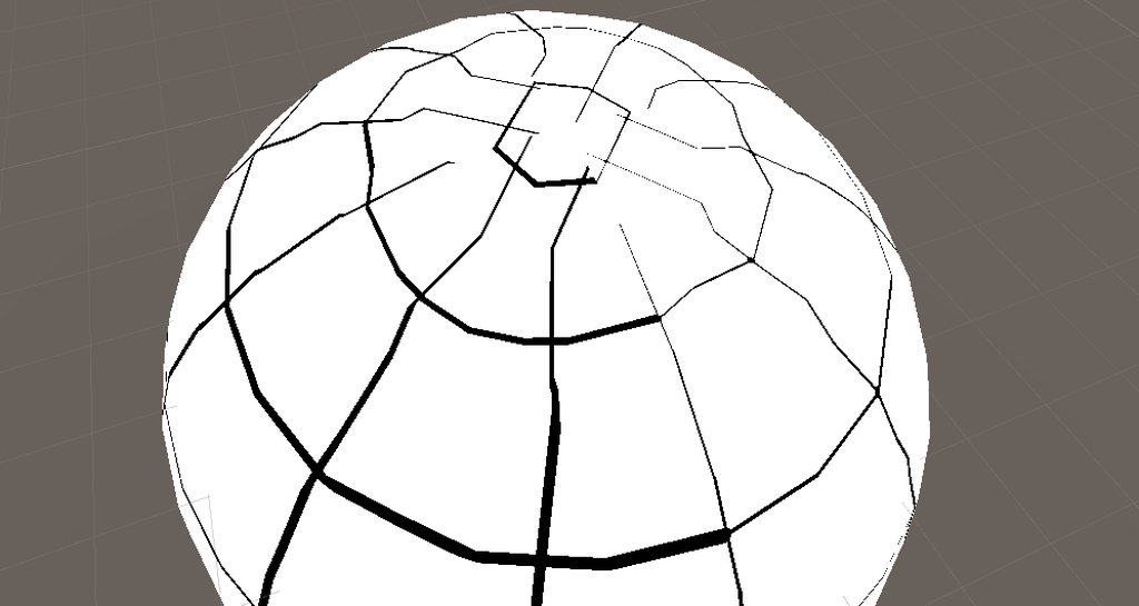
I'm looking to get some help on a specific shader i'm trying to reproduce. See that as a "case study"
I'm currently developing some tools for a personal projet and I made some code to "snap" on a grid at the surface of a sphere ( a planet in my context )
Where i'm struggling is to understand how can i reverse that code to show the actual grid on the sphere ( square-ish grid )
The grid type i'm trying to reproduce is something very close to what frostpunk & Dyson sphere program did.
If anyone is interested by the problem please let me know. I'm currently reading about shaders to be able to do it but I still struggle on that. ( I'm an experienced programmer learning technical artist stuff for fun & to get better in my own job )
Here is a very simple example of what i'm trying to do :
If I have a code that define position on the grid like :
float3 positionMouse;
float3 positionSnap = float3(math.round(positionMouse.x,positionMouse.y,positionMouse.z));
How do I figure out the formula/code that give me output for the "frag" function in the shader code to render the grid lines ?
Question about shader variant collections:
this show to shader I need, but when I open it I can see
- first: {fileID: 10770, guid: 0000000000000000f000000000000000, type: 0}
so guid does not show direction to shader in question, so I cannot access it in other ways. Anyone knows how to get shader name from fileID only or other way from shader variant collection?

Does anyone know why vertex position works great for unity primitives but does not work properly for blender primitives? (blender on top unity on bottom)


How can I sample _CameraDepthNormalsTexture in unlit urp 12.1 shadergraph? I've set up ConfigureInput in my renderpass already, can't find documentation on sampling it.
I would assume I can use a custom node and output a texture2d of _CameraDepthNormalsTexture
But it doesn't work

figured out this much
but now its screaming at me about redefinition of _Time
I think it's conflicting because Shader Graph includes it's own ShaderLibrary files (only for preview purposes in the editor). It can't just use URP's one, since it needs to support all pipelines.
So basically need to surround any includes (and code relying on them) in #ifdef SHADERGRAPH_PREVIEW. e.g.
#ifdef SHADERGRAPH_PREVIEW
#include "Packages/com.unity.render-pipelines.universal/ShaderLibrary/DeclareNormalsTexture.hlsl"
#end

void CameraNormals_half(float2 UV, out float3 Out){
#ifndef SHADERGRAPH_PREVIEW
// set values for preview purposes in the graph
Out = float3(0, 0, 1);
#else
// values actually used for final shader
Out = SampleSceneNormal(UV);
#end
}
Color is passed into the vertex colors of the mesh. Can obtain it in ShaderGraph with the Vertex Color node.
You should be able to produce a mask per face - I imagine you're already doing that since you managed to texture each face differently. You'd just need to use that UV in those 6 texture samples, no?
Or is each face combined into a single texture? I suppose you'd then offset the UVs themselves 6 times and then combine, masking it in a similar way. Then put the result into the UV port on the texture sample.
seems that specific process was waiting for a shader to be loaded, includiing the shader in the preload list solved it
Hi, I have this texture and I'm trying to make it fit a subdivided plane, what's the best way to do it? I tried using tiling, but ended up having to twiddle with the values to make it even fit. I feel like I'm missing something...


This is what I get with dimensions at (320, 240), the size of my image and plane
The plane has 240 height and 320 width cuts
How to access the color of a sprite renderer inside the shader? Is there a identifier there?

It's passed through the mesh vertex colours (Vertex Color node in SG, or COLOR semantic in vertex shader input struct in shader code)
thanks
Worked like a charm!
I'm honestly lost on where to start fixing this


put the UV through a tiling node first then you can change how it's tiled
is Colour the name i should use in script? i thought i needed to make a ReferenceName ?

Is there a way to convert a project from HDRP to URP? Or will i have to make a new project from scratch?
click on it and open the graph inspector, and then you can change the name it actually uses in the code. Colour is just the name it'll show you, not what it actually uses in code.
Nothing automatic, you have to convert it manually
how do i import an external shader file on runtime?
You don't
are there any workarounds?
I never tried this myself, but maybe asset bundles/addressables can do it
yeah i was searching on how to use the asset bundles but i didnt really understand it
im trying to make a mod for a game so that is uses a 360 panorama camera, but it uses a shader so yeah
is there a good way to pixelate the output of a shader?
nevermind i figured it out lol
ahh i see thankyou so much! also this is a bit of a side notw but thankyou so much for the blit scripts they are a life saver!!
How can I fix that issue with my shader ?
My code look like that :
        float2 RadialCoords(float3 a_coords)
        {
            float3 direction = normalize(a_coords);

            // Get a longitude wrapping eastward from x-, in the range 0-1.
            float longitude = 0.5 - atan2(direction.z, direction.x) / (2.0f * PI);
            // Get a latitude wrapping northward from y-, in the range 0-1.
            float latitude = 0.5 + asin(direction.y) / PI;

            float2 sphereCoords = float2(longitude, latitude);

            return sphereCoords;
        }

        fixed4 frag(v2f fragCoord) : SV_Target
        {
            float2 uv = fragCoord.uv;
            float3 snap = GridSnap(uv);
            float2 equiUV = RadialCoords(fragCoord.normal);

            if ((snap.x - equiUV.x) >= 0.0001 ||
                (snap.y - equiUV.y) >= 0.0001)
            {
                return float4(0.0, 0.0, 0.0, 0.5);
            }
            return float4(1.0, 1.0, 1.0, 1.0);
        }
In the shader 🙂
Thanks for the help !
Hi folks, I'm a bit of a shader newbie here. Got a small and hopefully easy question. Is the shader graph just essentially a nice UI wrapper around writing a shader in code? Is there anything that can be done in the graph but not in code, or vice versa?
@charred meteor nope, not as far as I know 🙂 Everything done in the graph is able to be done in the code & vice versa
It just require some custom node & stuff to execute some functions if you do complex stuff
Great, thanks very much! I'll have another question later but I need to dash out now 😛
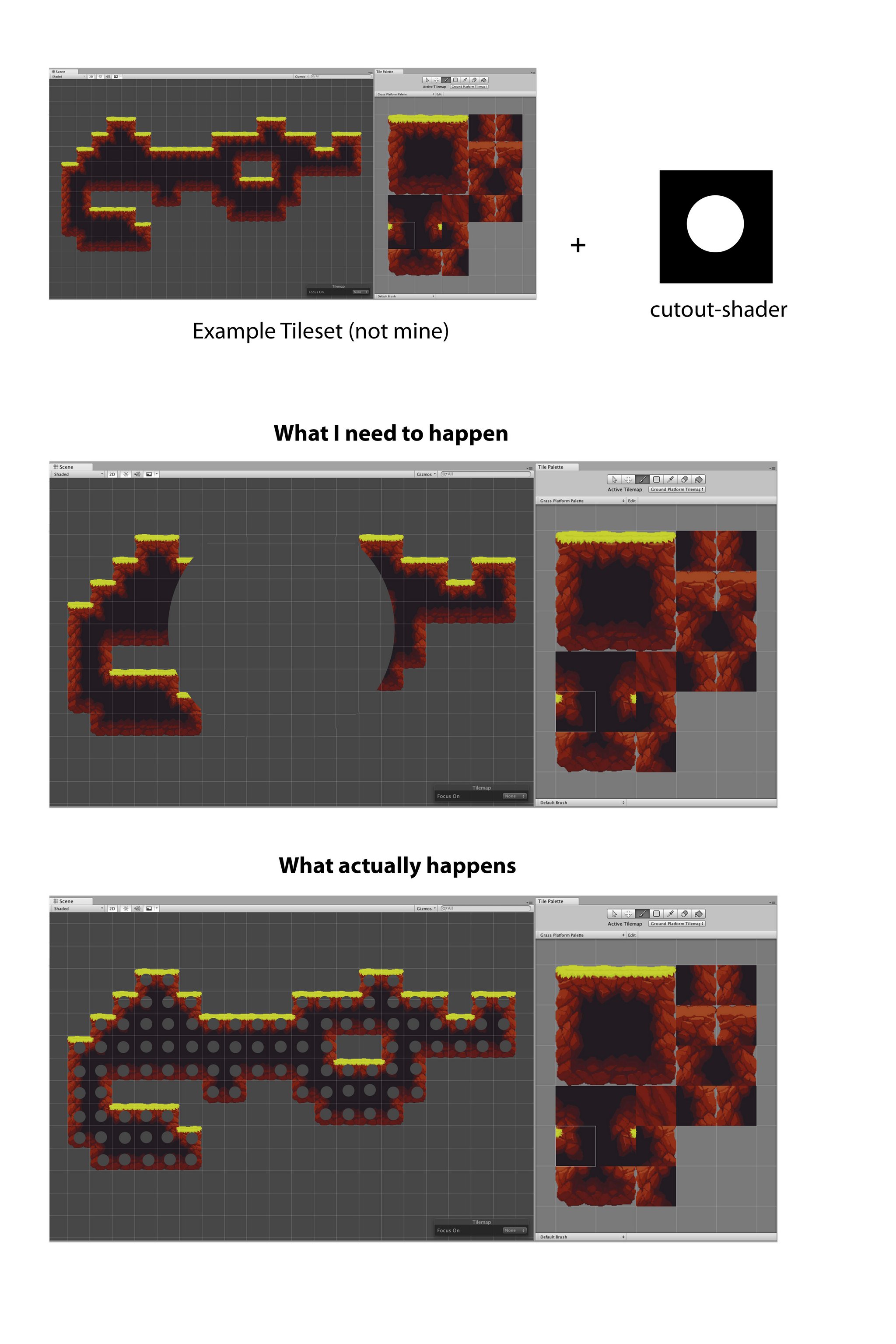
Actually Ive probably got time to type it out:
So, im wanting to do something very similar to what this person was doing in this thread
https://forum.unity.com/threads/apply-shader-to-tilemap-as-a-whole.963252/
Essentially, apply my shader to the whole tilemap as opposed to individual tiles. The difference being that my shader is written in code rather than using the graph, and I'm unsure as to the exact steps I need to take in order to get it to work correctly. The thread mentions using some kind of conversion on the UVs in order to get it to sample the map as opposed to the sprite, but I'm not sure how I do that conversion in code (It appears to be a node in the graph)
Unity Forum
Hey there,
as I am testing around with the new shader graph I tried to apply some shaders to tilemaps.
The problem is that the shader always gets...
If someone could point me in the right direction that would be very helpful, thanks 😄
Use the position values as input for sampling the texture instead of the UVs
Oh really, its that simple? So the tile coordinates? (0,0)(0,1) etc?
More the vertex coordinates
Forgive my ignorance, how am I able to calcualte that (And also I apologise as I have to head out now, but thank you!)
I think that the reason for your issue is just how the normal value is interpolated between the vertices, and you can't really do anything about that.
You don't calculate it, you just read it in the shader. This is what's done in this post of the thread you mentioned : https://forum.unity.com/threads/apply-shader-to-tilemap-as-a-whole.963252/#post-7285807
Unity Forum
Hey there,
as I am testing around with the new shader graph I tried to apply some shaders to tilemaps.
The problem is that the shader always gets...
Much appreciated, I’ll try this out later!
@amber saffron what would be your approach to do something like a building grid on a sphere like Dyson sphere program do ? ( or frostpunk , but on the sphere )
Just don't forget to enable tiling on the texture import settings like he did ^^
Taking dyson sphere program as example, having a way more defined sphere would greatly help 😄
I have a very vertex intensive sphere already calculated so that's not an issue on my side 😄
And seeing that I used to mod their game for fun i'm kinda aware on how they segment their sphere
The point i'm stuck at is creating the shader that show the building grid on top of the sphere ^^"
Like that one

The two things I found that could explain how they did it would be that paper :
https://www.sciencedirect.com/science/article/pii/S0925772112000296
And that tool :
https://github.com/penguian/eq_sphere_partitions
When i'm looking at their blog post there is that image : https://i0.hdslb.com/bfs/article/watermark/4e8c484ac9cadb178210b6a61b601fd6eed65b73.png@942w_512h_progressive.webp
That look awfully like a Healpix repartition : https://healpix.sourceforge.io/ ( first set of images ) --> https://healpix.sourceforge.io/images/gorski_f1.jpg
But where each section is put in a specific chunk to optimize the drawing of the sphere.
Once the segments are created I get they store the number of desired divisions for each lattitude so it divide into the desired amount of big square, and then devide again into 5x5 grids
The part I don't get is how to translate that into a shader that show the grid on the sphere. & where to find documentation explaining something similar so I can try & test by myself & learn from it
Hey I need to create a panning effect for a texture with dynamically changing speeds. I'm using Amplify for creating my shaders but the logic will still the same. Normally I use the Time node as an input for my Panner, and if I want to change the speed of it I just use a float as a scalar. However, for what I want this doesn't work - this is because it's multiplying Time (which is the amount of time since the program has run) by a value. So if I want a smooth speed-up transition it will look "jumpy" so to speak.
Does anyone know of a possible solution to this problem?
I was thinking, if it's possible, to instead use DeltaTime multiplied by a float and somehow accumulate that into a variable and use that in the Panner, but are persistent variables even possible in shaders?
I must say that I'm quite confused, I did similar maths to what you did (but in shadergraph), and ended with nicer lines :

You can't do this with only shaders, the best is to expose a "time" variable that is set by a script that is doing the time & speed calculation
Looks way better than mine for sure yeah ... Would love to see how you did that.
The size of the line are still distorded the closer you get to the equatorial region of the sphere tho . I wonder why, probably a projection issue
I suppose there is no way of reverse engineering a shader in a unity game right ? ( for learning purposes ) I'm dying to understand how they managed to do that building grid
This is what I ended up doing
I wasn't sure if there was a better way
but it's working

Technically, it's possible.
Some tools exist to decompile games, but I won't say more than this.
Other more "legit" solution is to use graphic analyzer tools like renderedoc to look at the shader 🙂
@amber saffron no worries on that. I modded the shit out of their game for galactic scale mod so I know how to get the code and the compiled shader & all.
But my point is not to steal but to learn & try by myself to get a similar result, just because !
For the longitudinal lines width, with this simple shader it is totally expected, as the more you get close to the poles, the more the "grid" is dense, and since the lines are drawn with a simple if x < 0.001 comparison, it makes sense.
You could thicken the line (the variable that selects where to draw the line) depending on the lattitude
I wouldn't be surprised if they had a dedicated mesh for the planet/grid
Yeah, the same way I could , depending on the latitude increase the numbers of segments.
And nope they have only one mesh, the one of the planet.
And they have a shader named "buildinggrid" that calculate the grid on top of the mesh.
For the mesh part I managed to make my own pretty easily, that's no issue, adding perling noise on the vertex on the mesh is no big deal either.
For the grid they have a set of snapping function that do a bunch of calculations. the main point is that they have 1 big array of "segment" and depending of the lattitude where you are.
like that the first image ( it's my code that do a similar stuff than their own code )
And then the snap function do something like that based on the lat / long of the point of the sphere you are in
public Vector3 SnapTo(float longitude_rad, float latitude_rad)
    {
        float f = latitude_rad / TAU * segment;
        float longitudeSegmentCount = DetermineLongitudeSegmentCount(Mathf.FloorToInt(Mathf.Max(0.0f, Mathf.Abs(f) - 0.1f)), segment);
        latitude_rad = (float) (Mathf.Round(f * CellNb) / CellNb / (double) segment * TAU_DBL);
        longitude_rad = (float) (Mathf.Round((float) (longitude_rad / TAU_DBL * longitudeSegmentCount * CellNb)) / CellNb / longitudeSegmentCount * TAU_DBL);
        return new Vector3(Mathf.Cos(latitude_rad) * Mathf.Sin(longitude_rad), Mathf.Sin(latitude_rad), Mathf.Cos(latitude_rad) * -Mathf.Cos(longitude_rad));
    }
The segment table was easy to reproduce because it come from a texture and we had understood how the repartition worked while working on Galactic Scale Mod 🙂

I have managed to make a mask for those six faces yes, but I'm not experienced enough to know how to use it on the other effect the way you are descriving.
The mask is just a black and white texture, but its precisely on those surface faces like that, its not suspended in the material the way the other depth one works
the first big graph produces the depth effect, and thes second big graph maps different textures onto the six faces, but I can't figure out how to combine those two together


I want this, but I want different textures on each face, which I can't figure out how to do.
I also wants lots of other things after this but those are problems I face after I manage to do this little

hrm actually after looking at that more closely, it still doesn't do what I want
I want to fake interior depth, layers of it, something like this or this where you can CLEARLY see there is something "inside of it"


and the something has volume and changes depending on viewing angle


really good example
Wouldn't it be more convenient to just use a texture? (Though for changing the number of segments in a shader, take the sine of floor(N*angle)/N where N is the number of latitude segments divided by 2 pi, multiply by some number A, floor it, multiply by 4 (if you want it to have four-fold symmetry); 4*floor(A) = number of segments on the equator.)
Actually floor(N*angle)/N would need to be modified slightly to be right but it's close
maybe 2pi*floor((angle*N/2pi+1)/(N+1)
but that would be my rough idea anyway
They Generated it with a texture at first so I guess it def make sense. but for the purpose of testing I'm experimenting first.
And seeing that for me it's easier to manipulate an array rather than dealing with a texture at that point ...
I'm trying to use float3 TransformObjectToWorldNormal() in #include "Packages/com.unity.render-pipelines.core/ShaderLibrary/SpaceTransforms.hlsl" but it's returning all black for some reason? if I remove it and just return the object space normal it looks like what you would expect.
yeah fair, though I am sure it is possible to procedurally generate
hard to visualise how can that formula can define the segments numbers tho Oo
yeah definitely possible especially for testing ppurposes of differents configuration of segments
It should step the angle between 0 and 2pi (but always remaining in between, never equal to zero or 2 pi so that you don't have a region with zero segments). Taking the sine would give you something proportional to the circumference at that angle, which we want to be proportional to the number of segments, but we have to turn it into steps again because we want integer numbers of segments. Then multiply by some number for nice symmetry.
Then multiply by some number for nice symmetry --> that's what would define the 4 quadrans in the example right ?
and I guess that would not induce any issues to just output the color of the line in the "float3 frag(interpolators i) : SV_Target" function of the shader. The distortion should not happen because you are already working with the correct angles.
In your example the angle is the angle between the equator & the uv coordinate of the interpolator , right ?
If I remember well it's something like : acos(u) asin(v) that can give me that angle am I right ?
It might if the color bands are thinner or as thin as the separation between vertices, otherwise it shouldn't. The angle is the polar angle, though instead of 2 pi it should just be pi. I think the angle should be proportional to one of u or v
fair enought ...
I'll try that this evening to see how that method look.
(just change Nlon, Nlat, Nsym at the top)
tbf I had a lot of it lying around so most of the work was done for me
My god it's looking very similar like DSP splitting
at least for the big 5x5 area
if you have lying around a way to do the x*x grid in the segment or know how to do that i'm taking the explanation
yep just did the minor gridlines
The important parts are just where it's dealing with the angles, most of it is boilerplate stuff for making/using a sphere
(btw the way I made the lines look roughly equal in thickness at the poles and at the equator is by dividing by sqrt(sin(angle)) but that's a bit hacky and imperfect, there's probably a better way)
@tight phoenix https://docs.unity3d.com/Packages/com.unity.shadergraph@14.0/manual/Refract-Node.html this could be useful for you
Ill look into it 🤔
Sure you need to fake it? It would be trivial to physically put the geometry in there
If you want refraction I think it'd be much harder (unless you do some screen space approximation)
i'm checking the code in detail and implementing it in a unity shader to play with it.
and on a bigger mesh because currently if i'm putting big number it's not looking good :

You could always have it in the fragment part to have it always look sharp (at the cost of performance)

ah that's just bc the shader isn't antialiased
Will definitely experiment with that
were it to include antialiasing it would just look like a green blob
yeah that's what I thought but hey the code is here and I guess that I get how you did and the math behind are clear
you can zoom in by moving cameraPos closer to -1.*cameraFwd
though it might also be worth randomising the angles otherwise the grid cells are all uniformly offset diagonally from one another and it might look a bit weird
(just add some random value calculated from thetaCoord onto spherePhi just before the if statements)
hummm I mean the offset between the longitudinal segment are not that bothersome I would say
it's expected ( if that's the offset you are talking about )
from one latitude to another they're all aligned diagonally if you have some very large number of them
like this

can i still use cginc files in URP even though its using hlsl files? they are almost the same right? so i should be able to change my custom file into a hlsl instead of a cginc?
you can use cginc files as includes
oh so i can just use them without a problem then?
why do URP use hlsl files instead then?
ok, ill just not worry about it then as long there is not a problem
does GetMainLight() (in URP) only get the directional light or is it usable with using multiple lights?
im guessing because of this that GetMainLight().distanceAttenuation is the URP equivalent to LIGHT_ATTENUATION()
// Abstraction over Light shading data.
struct Light
{
    half3   direction;
    half3   color;
    half    distanceAttenuation;
    half    shadowAttenuation;
};
that's what i'm doing, just taking the calculation in it just to visualize for now.
Quick question tho. the SphereNormal Method by what would you replace it in a unity shader context ?
If i'm using the normal position it give me that :
Just the normalised position

If it's a unit sphere, then just position is fine
LoL I think I messed up somewhere x)
fixed4 frag(const v2f fragCoord) : SV_Target {
                float4 frag_color = float4(0.2, 0.2, 0.2, 0.2);

                float3 normal = fragCoord.normal;
                float sphere_Theta = asin(normal.y);
                sphere_Theta += PI * 0.5;
                const float int_Theta = (sphere_Theta / (PI) * _Nlat + 1.);
                const float theta_Coord = PI * floor(int_Theta) / (_Nlat + 1.);
                const float lon_mult = floor(floor(_Nlon / _Nsym) * sin(theta_Coord)) * _Nsym;
                float sphere_phi = atan(float2(normal.x, normal.z));
                sphere_phi /= (2. * PI);
                sphere_phi *= lon_mult;

                if (fract(int_Theta * _Ngrid) < _GridLineThickness || fract(1. - int_Theta * _Ngrid) < _GridLineThickness || fract(sphere_phi * _Ngrid)
                    < 0.05 / sqrt(sin(sphere_Theta)) || fract(1. - sphere_phi * _Ngrid) < _GridLineThickness / sqrt(sin(sphere_Theta)))
                {
                    frag_color = float4(0, 0.8, 0, 0);
                }
                if (fract(int_Theta) < _GridLineThickness || fract(1. - int_Theta) < _GridLineThickness || fract(sphere_phi) < _GridLineThickness /
                    sqrt(sin(sphere_Theta)) || fract(1. - sphere_phi) < _GridLineThickness / sqrt(sin(sphere_Theta)))
                {
                    frag_color = float4(0, 1, 0, 0);
                }

                return frag_color;
            }
this is what I've done in the frag function
float sphere_phi = atan(float2(normal.x, normal.z)); --> this line had to change it a little
because that : float spherePhi = atan(normal.x, normal.z); was not supported in the shader
i think it should be swapped to atan2 rather than atan(float2()) which presumably does an elementwise atan

Already tried but giving me weird shit xD
it may be my normal position that is weird
Maybe switch from normal to normalize(position)
if normal isn't the world space or object space normal normal
ah yes
raaaaah shaders are so complicated when you don't know what you do with them grrrrr
you could do it in shader graph if you don't plan on doing anything that needs loops or whatever
yeaaaaah I guess
but here I just need to get the correct variable to replace the normal position and I think i'm good
the question is .. how ? xD
UnityObjectToWorldDir -->

I think it might be in view or tangent space?
Lol I'm giving myself an headache trying everything i can think off xD

Getting some very weird effects xD
No clues :/
I'm checking online but can't find what I need for that ^^"
https://docs.unity3d.com/Manual/SL-VertexFragmentShaderExamples.html
o.worldNormal = UnityObjectToWorldNormal(normal); --> they do that to get the surface normal of the mesh but don't seem to work
is there an easy way to grab a depth normal texture when coding a shader?
Maybe try just using that as the vertex color and see when it looks like the right thing?
Not sure what you mean, how would I know if it look like the right thing ? 🤔
float3 GetViewDirection(float2 texcord)
{
    float4 viewVec = mul(_InvProjMatrix, float4(texcord * 2 - 1, 0, -1));
    viewVec = mul(UNITY_MATRIX_M, float4(viewVec));
    viewVec.x = -viewVec.x;
    viewVec = normalize(viewVec);
    return viewVec;
}

float GetDepth(uint2 posSS, float2 texcord)
{
    float cameraDepth = 1 - LOAD_TEXTURE2D_X(_CameraDepthTexture, posSS).x;
    if (cameraDepth != 1)
    {
        cameraDepth = lerp(1 / _ProjectionParams.y, _ProjectionParams.w, cameraDepth);
        float normalizeFactor = GetViewDirection(texcord).b;
        cameraDepth = cameraDepth * normalizeFactor;
        return cameraDepth;
    }
    else
    {
        return _ProjectionParams.z ;
    }
}
``` this is what I had in an old HDRP shader to get the depthit should be green on top, blue on one side, and red on the third side (then black on the last quadrant)
like this

(though this looks like maybe they got the inside instead of the outside)
not affected by the camera rotation or anything , right ?
It shouldn't be

then plugging it into the shader should work, no?
fixed4 frag(const v2f fragCoord) : SV_Target
            {
                float4 frag_color = float4(0.2, 0.2, 0.2, 0.2);

                float3 normal = fragCoord.normal ;
                float sphere_Theta = asin(normal.y);
                sphere_Theta += PI * 0.5;
                const float int_Theta = (sphere_Theta / (PI) * _Nlat + 1.);
                const float theta_Coord = PI * floor(int_Theta) / (_Nlat + 1.);
                const float lon_mult = floor(floor(_Nlon / _Nsym) * sin(theta_Coord)) * _Nsym;
                float sphere_phi = atan2(normal.x, normal.y);
                sphere_phi /= (2. * PI);
                sphere_phi *= lon_mult;

                if (fract(int_Theta * _Ngrid) < _GridLineThickness || fract(1. - int_Theta * _Ngrid) < _GridLineThickness || fract(sphere_phi * _Ngrid)
                    < 0.05 / sqrt(sin(sphere_Theta)) || fract(1. - sphere_phi * _Ngrid) < _GridLineThickness / sqrt(sin(sphere_Theta)))
                {
                    frag_color = float4(0, 0.8, 0, 0);
                }
                if (fract(int_Theta) < _GridLineThickness || fract(1. - int_Theta) < _GridLineThickness || fract(sphere_phi) < _GridLineThickness /
                    sqrt(sin(sphere_Theta)) || fract(1. - sphere_phi) < _GridLineThickness / sqrt(sin(sphere_Theta)))
                {
                    frag_color = float4(0, 1, 0, 0);
                }

                return  frag_color;
            }
That , give me -->

So I would argue that nope xD something is wrong x)
( the #define Nlat 9.
#define Nlon 32.
#define Nsym 4.
#define Ngrid 5. are the same on the material using the shader than your shadertoy )
wait it should be atan2(normal.x, normal.z)
hopefully that might solve something
in this line: float sphere_phi = atan2(normal.x, normal.y);
also in the first line of ifs you forgot to swap a 0.05 for _GridLineThickness
Omg
Also just as a note, if _Nlon = 2*_Nlat then the grid is square on the equator
how did I ended up swapping a Z for a Y
easy typo to make

yep pretty neat !
Nice! I think the issues there are bc the sphere is too low-resolution (the normalised position might help though it might not)

Ah right, glad it works :)
Quick question , what part define the width of the bigger segment and what part manage the grid lines ?
You mean the thicker/thinner grid lines?
I love you ❤️ and it's pretty simple to understand the code too 🙂
yep
The first if governs the thin lines, the second one does the larger ones
The ratio of square size to grid line thickness should be the same for both
(so there are _Ngrid times more small gridlines, and they're _Ngrid times thinner)

Alright added some modifications but look pretty good
I'll have to play a bit with the code and make a function that "snap" on that grid
but I think it's doable 🙂
Oh I just figured out an exact way to have the line thickness be uniform: https://www.shadertoy.com/view/sdKBD3

And figure out how to mimic the distribution of segments
wait no it doesn't work at the north pole
there we go
(rather than having the thickness/sqrt(sin(thetacoord)), do thickness*min(PI-thetaCoord, thetaCoord)/(sin(sphereTheta)))

:)
Where exactly is the number of segment defined ?
is it : lon_mult ?
That part : floor(floor(_Nlon / _Nsym) * sin(theta_Coord)) * _Nsym , right ?
Because , let's say you wanna fine tune that. how would you say : between x & y lattitude I want : N segments
They're created evenly spaced in latitude, so if you want to change that you'd need to put int_theta through some function to make it grow more quickly where you want denser spacing, and less quickly where you want sparser spacing
It puts a line every time int_theta is an integer
int_Theta --> that's the number of segment on the longitude , gotcha
theta_Coord --> what's it's role the ?
theta_coord is the stepped angle, corresponds to the angle at the center of each segment
int_theta is basically the angle, but rescaled so it's zero at one pole and _Nlat on the other
_Nlat + 1 in fact
lon_mult = the floored line value , same than int_Theta it put the line on the longitude when it's an integer
& sphere_phi ?
nvm lon_mult is the symetry number
So I guess it's used to be sure that the parition is good where you are
Anyone use shader graph with the built-in render pipeline? I'm trying to figure out why the scene color node doesn't appear to be working, or what the BIRP equivalent is
hey, is it possible to alight trail effect in 3d view ??
does anyone knows how to fix the alignment of the trail to match the object ??
https://docs.unity.cn/Packages/com.unity.render-pipelines.high-definition@12.0/manual/Feature-Comparison.html Feature comparison says that there is no color texture... is that what scene color node usually samples?

i've been told that shader graph simply does not support the built-in pipeline at all
i tried to use it and got an almost-there result with some bizarre bugs
Fair enough, the Unity docs seem to suggest as much.

"compatibility purposes only"
whatever that means
hey guys
can you guys give me some suggestions for improving gameplay and ui here
https://www.youtube.com/watch?v=3MU_NFWVX2Y

Hello again everyone. I'm having a bit of difficulty understanding how to accomplish something with a shader and a tilemap.
Please note that what I describe below isn't actually what I want to do, but I feel its a simpler example for illustrating the thing I am having an issue with.
Also please note that I am coding this as opposed to using the Shader Graph. Additionally, if relevant, the tiles I am working with are loaded an atlas as opposed to the original source texture.
So in essence what I wish to do is traverse the entirety of my tile map and make adjustments to colour of the texture of the tiles based on their location in the tilemap.
The simple example of this would be having a tilemap where I wished to apply a gradient across the whole map, where any pixels on the left-most edge were completely unchanged, and on the right most edge were completely interpolated to the gradient color. I understand the principle for carrying out the could changing (i.e Lerp(TextureColor, GradientColour, XPosition) but I am unsure how to go about getting the "correct" XPosition for a number of reasons:
- I am unclear as to what vertex the shader is referring to when dealing with a tilemap. Is it talking about the vertices of the individual tile, or the tilemap as a whole?
- How do I ensure that the verts refer to the visible extremities of the tilemap? I.e, it reaches as far as there are sprites in the map, and no further
- What kind of conversion do I need to do with the verts in order to make sure that they are in the space of the tilemap, rather than worldspace etc.
If anyone could give me some help with this, I'd really appreciate it.
I've made a horrible little picture to give some more context

I'm pretty sure that you can use the vertex position.
The tilemap is rendered as a whole object, so the vertex position will be relative to the tilemap pivot point.
To make your gradient, you'll have to apply a scale and offset to the X value of the position, taking values according to the leftmost and rightmost tile
Those values can't be calculated directly from the shader, you'll have to pass them to the shader/material manually or calculate them via a script
Ah thats probably where I'm going wrong, thanks so much!
Ill give this a go and let you know 🙂
Uhm... Does anyone know why this is happening?


It only happens in scene view thankfully, but I'd still want to know what is causing that
Hello, I have a shader with two passes, the first one is intended to render an outline but culling the back faces of the geometry. And the second one is just a cell shader. However, for some reason only the first pass has an effect. and the underneath geometry isn't rendered at all. In the screenshot below you should be able to see both the current effect of the shader and my parameters, the outline color is black, and my regular geometry albedo color is red. Therefore the red geometry should appear with the outline, which it is not.
Here is my code if anyone can help me --> https://pastebin.com/ncQ64MCF

Pastebin
Pastebin.com is the number one paste tool since 2002. Pastebin is a website where you can store text online for a set period of time.
ive gotten a little stuck getting additional lights to work in URP. anyone got any pointers? ive tried reading a couple of URP shaders. and i am aware that in URP does not use second pass for rendering additional lights but i have not been able to figure it out so far. any pointers?
Good day gents! I have a small question about a gradients in shader graph.
I want a base colour to be a gradient, how can I achieve this? What time value should i put in Sample Gradient?

the time name of the value might be a little misleading. all it means is that its a value between 0 and 1. its like the gradient is on a range from 0-1 and the t selects which color from the gradient
if you want to create a gradient, one solution might be using lerp(colorA, colorB, uv.x)
TY! Found that solution on YT
Im trying to copy Brackeys Outline tutorial but it isnt working for some reason
Does it work in 2022 and with URP?
It looks fine in the preview but not outside of that
The outline is either tiny and doesnt change based on what I set the offset/thickness to
Or is works mostly fine but has black chunks around the sprite, some problem with the alpha
Any help?


By checking some old messages I found I could change the sprite to full rect to fix the outline
But one problem causes another
Now the alpha transparency is not working with the sprites so they have square black backgrounds
Theres apparently some sort of "Surface Options" but I cant find them anywhere
In the graph settings for surface option
And since you're outputting a constant 1 alpha, obviously it is opaque
Has anyone tried out the new render pass functionality in 2023.1A (out today)? It seems pretty nice. Framebuffer access from previous subpasses. It seems to completely replace the set / clear render target X methods with a streamlined render pass that Vulkan and OpenGL drivers use with a fallback option with the trusty set render target sequence for DX11 and DX12. But how does it set which shaders to use and what to draw?
2023 is probably a few years from now from being available to my current project. Shame.
Having pixel framebuffer access from previous shader passes within the same draw call would be incredibly nice. Simplifies my current juggling of render targets quite significantly if it's what I think it is.
Can someone please have a look at my issue regarding culling in shaders?
for some reason i cant connect my normal from texture to my normal node

Normal From Texture can only be used in the fragment stage. You'd typically connect it to the "Normal (Tangent)" port
Its intended to produce a normal map from a height map though. If you already have a normal map, use Sample Texture 2D instead with Normal mode.
Is this in URP?
If so, URP doesn't really support multipass shaders. You should split it into different shaders and assign two materials to the MeshRenderer. Or use RenderObjects feature to re-render objects on a specific layer with an override material.
hey, I've been asking for this for 2 days now, is not possible to align this trail perfectly with the sword??
No
Damn, I wish wishing to prevent myself from having to add an extra material too all materials in my project :'( do you know of an easy way to do this?
is there an URP equivalent to UnityObjectToViewPos?
does that get the screen position of the current pixel / vertex?
ComputeScreenPos() in the vertex shader, use built in : VPOS shader sematic for a fragment shader.
im not exactly sure of the actual terms but it should transform the input to view space
Like the UV position on the resulting camera texture? ComputeScreenPos() in CGProgram for vertex.
There's a mirror for core.include for URP but I stick with CG as it's easier.
And then a VPos * (_ScreenParams.zw - 1) for pixel UV as VPos returns the integer pixel coordinate.
screen pos is clip space right? so if i understand this should be different?
screen pos is not quite clip space I think
Transforms a point from object space to view space. This is the equivalent of
mul(UNITY_MATRIX_MV, float4(pos, 1.0)).xyz, and should be used in its place.
That's UnityObjectToViewPos
what im originally using it for is this float depth = -UnityObjectToViewPos(float3(0,0,0)).z; so that the halftone texture stays the same size no matter the distance from the camera

ok cool, ill try that
float depth = mul(UNITY_MATRIX_MV, float4(0, 0, 0, 1)).z;
well, negative that
if you make it custom you can
would be cool if there was a thing where the line comes out of another line, or mesh strip
I mean by default
Anything is possible with enough shader magic
I feel like this would be a useful component or trail option by default
all it would have to do is every frame connect the previous mesh strip with the new one with quads
Probably a geometry shader that takes an input of a circular buffer containing previous positions
Then extends the mesh out back to properly render a trail
well its doing something thats for certain, doesnt seem to completely replicate it. im getting some streching now. i had the same problem when i where first making the shader but i dont remember why it was happening. if i return the texture on a plane this is what happens. while it should look like a perfect grid of dots UV'd in screen space

wait hold on, there might be something else that isnt working
yeah, seems like the UVs arent quite working
looks like im missing GetVertexPositionInputs() for my screen pos
anyone happen to know where the definition of it is?
What is the performance cost of using Grab Screen Pos?
I am just using that and doing a color blend with it and that's it
why does this material receive such hard shadows?
The same happens when i remove the multiply by vertex color

set ambient occlusion to 1
or at least not zero
zero means you have no indirect lighting so when direct light is blocked then it's pitch black
hello
is there a way i can keep a texture size while it pans? my texture is 1024x1024
regardless if im actually using a square or in this case extending it a bit as a rectangle
its for some panning textures
Thank you
Where can i find the setting for that?
It's in the graph in the fragment node
Thanks!! Totally missed it
it works now :))
nice :)
GVPI is the standard vertex position converter for URP. Should come with the core include.
how do I customize that, its unity's trail effect ... i dont know if i could customize it
You code it yourself. Look at either the .shader code or the shader graph and go from there.
Question about shader variants. If I have two shaders that is almost identical. Lets say one of them have _NORMALMAP keyword and another doest. What would happen if I would add just one that Have _NORMALMAP tag and erase one without it. I would save on shaders, but how that would effect the project it self. In other words, can I just add shader variant with most keywords instead of all with less words? 😄
DIRLIGHTMAP_COMBINED FOG_LINEAR LIGHTMAP_ON SHADOWS_SHADOWMASK _ADDITIONAL_LIGHTS _ADDITIONAL_LIGHT_SHADOWS _MAIN_LIGHT_SHADOWS _RECEIVE_SHADOWS_OFF _REFLECTION_PROBE_BLENDING _REFLECTION_PROBE_BOX_PROJECTION _SHADOWS_SOFT
DIRLIGHTMAP_COMBINED FOG_LINEAR LIGHTMAP_ON SHADOWS_SHADOWMASK _ADDITIONAL_LIGHTS _ADDITIONAL_LIGHT_SHADOWS _MAIN_LIGHT_SHADOWS _RECEIVE_SHADOWS_OFF _REFLECTION_PROBE_BLENDING _REFLECTION_PROBE_BOX_PROJECTION _SHADOWS_SOFT _NORMALMAP
You can create your custom trail mesh renderer, but it's more of general code thing
Is this game's artsyle using a special shader for it's rendering?
Could this type of style be made with just a mesh renderer with unity's standard lit shader?
the game is cult of the lamb, made in unity
the character reacts to shadow and light so it's definitely not the sprite renderer, right?
sprite renderers can have shadow too, using custom shader
https://github.com/anlev/Unity-2D-Sprite-cast-and-receive-shadows/blob/master/SpriteShadow.shader
Most likely custom shaders are required, id imagine it would be really hard to get such bright and clean appearance by only using the default lit (3d) shader. It could be custom sprite shader with shadows tho.
@simple violet The shadows and shading are way softer than what you'd expect by default so there probably is quite a lot of work there, though I can't pinpoint what exactly
In addition to that there clearly is a localized "darkness" overlay as well as an animated "painterly" texture on everything
Hi guys im getting an error when i try to run my application on Android im getting this error:
2022-07-28 10:39:56.774 24694-24979/app.kokorokids.app.dev E/Unity: -------- GLSL link error:  The number of vertex shader storage blocks (1) is greater than the maximum number allowed (0).
2022-07-28 10:39:56.774 24694-24979/app.kokorokids.app.dev D/Unity: Note: Creation of internal variant of shader ‘Particles/Standard Unlit’ failed.
Some element are invisible since im getting this error, in the editor they work fine, i updated my unity engine to the 2020.3.37f1 to try to solve this error with out any luck.
I want to create a printed glass material like this

But I have no clue where to start, I followed some tutorial on youtube about how to make a glass material but this is very different
- easy / hacky method : use a texture to control the color and opacity to have the printed parts a bit more opaque & rought
- less easy but more realistic : control the refraction and refraction smootheness with a mask texture
Sounds like a shader/feature incompatible with your device.
Or the platform in general
Hi! I've been following this tutorial: https://youtube.com/playlist?list=PLFt_AvWsXl0eBW2EiBtl_sxmDtSgZBxB3. On episode 16, he starts coding a surface shader for the terrain. The problem is that I'm doing this in URP, as I need it in my project. Thus, I've created a shadergraph using a custom function node where I've put all the code from the surface shader, with the necessary adjustments, plus some boilerplate for it to work with shadergraph. Then, in a script, I'm using the Material.SetSomething methods to pass values onto the shader. I can't just use normal shadergraph properties as I need to pass arrays to the shader. Although the functions are getting called and there is no error at all, the values aren't actually getting to the shader and I'm just getting a completely transparent material. I haven't worked much with shaders, so I'm completely clueless as to what's the problem. The attachments are the shader function and the script that sends values to the shader(which doesn't work on its own). It isn't practical to provide more context about the project in this question, so heres a link to the github project: https://github.com/SebLague/Procedural-Landmass-Generation/tree/master/Proc Gen E16. All the C# scripts on my project are exactly the same, only the shader is different. Thanks in advance. Also, if this isn't the right channel, please let me know.
Heya! I'm trying to create a simple mesh and I'm not sure how to make sure I have the winding right (the mesh is created facing away half the time). Afaik the triangles array has to always be clockwise, but how do I achieve this?
Here is my code: https://gdl.space/imakilipug.cpp
(Shaders seemed closest to my topic)
you mean frosted glass? like the refraction is very blurry?
can we have different smoothness texture for refraction and reflection? because in HDRP refraction material it is using smoothness from reflection.
Nope, you can't have different smoothness for refraction and reflection, unless going to a custom refraction effect in shadergraph
I am using this to make a camera facing billboard shader and it is working fine. But I want it to face the camera keeping its vertical orientation intact. I mean if I move the camera up or down it shouldn't rotate.

I guess you'll need to compute a custom rotation matrix for this
@amber saffron okk. so transform matrix inverse view is 4x4 or 3x3 matrix?
I was trying to find more info about the transform matrix but couldnt find much
4x4
I oftenly get confused when working with matrices, but iirc if you just want a rotation matrix that is aligned with camera X and world Y, you could build one with this in the rows :
0. camera right vector
- world up
- world up CROSS camera right (or the other way around if the vector is inverted, I never get the cross product in the good direction 😄 )
alright! thanks for the info.
Would it be possible to make a shader that like blends Meshes? Something similar I guess to how devil trigger works on DMC, where you have Mesh#1 and like a dissolve effect revealing Mesh#2?
@amber saffron okk so which nodes in shader graph will give me the camera x vector and world y vector? position nodes?
As the final values need to be in object space you can :
- Use a "tranform" node, to transform (1,0,0) from view to object, in direction mode
- Similarly use "tranform" node to transform (0,1,0) direction from world to object
sorry im a total noob with shadergraph, apologies if the terms im using are wrong. im trying to make a shader with a node that controls the fragment alpha like this: I can input a 2d array of values between 0-1 (from a script) and it will output the value 0-1 for the given uv coordinate of the fragment. Does that even make sense? Which node could I use for that?
Sounds like texturing with extra steps
my levels are generated randomly with tiles, and Im trying to figure how i can create random patches of various different textures (dirt, grass, rocks), so my thinking is i can create a big noise map for the whole generated level, and then apply sections to each tile
with a few ground layers for each texture, using the alpha to blend in and out with the noise map
Im not an expert on shadergraph but to me it sounds like this would be easier with just shadercode
I assume you would need to make custom nodes anyway
so when you say texturing, do you think that would work for my use case?
I don't know, hard to completely understand what you want. But from what i do understand it seems likr you might want to find another solution
The reason i said that is because a texture is a 2d grid
i want to apply random patches of different textures to the ground, which is generated somewhat randomly
maybe my level generation just doesnt really vibe well with doing this
Well its definitely possible, im not the best person to answer this though
My first instinct would be generating some kind of noise map for the world generation and use that in the shader as well to apply different textures
yeah thats pretty much what i was trying to say
i want to apply a section of the noise map to each "tile" in the map
i thought maybe there was a node i could pass in such an array and it would return then value of 0-1 based on the uv
No you won't need to do that yourself ad far as i know
I think not, you can just use a sample texture node to blend between textures for different materials - say, grass, dirt, rocks...
There are some sample noise nodes
Gradient noise, Voronoi noise, and Simple noise are the ones you get
the sample noise works fine for an individual tile, the prolbem is that when the tiles are placed, the textures dont line up
Use the world positions instead of object space positions
the world space positions will line up if the tiles line up
hmm ok, not sure how to do that but ill experiment a bit
When you have the vector2 to put into the sample noise node, instead of putting in the UV or something, put a position node and set it to world space, swizzle it to get the xz components, then put that into the sample noise node
I have been doing some googling into subsurface scattering - its very nontrivial to do, however for my specific use case, the volume I am trying to give the appearance of SSS is a cube of known, fixed, dimensions.
Within the confines of 'its a cube', I wouldn't have to bother with depth buffer checks and stuff right?
I have been trying to find resources to figure out how to do it in shadergraph, I have gotten tutorials that show how to take in the scene light's direction, but most tutorials talk about extremely complex SSS, so I havent had much headway there
thanks a lot, i think this is going to work
giving the appearance of SSS really just involves adding some emission near where the dark side begins; you can get all fancy with physically accurate this and that but it doesn't need to be all that complicated really
if you could make the cube smooth shaded (by removing excess vertices) and then set the normals in the shader to flat shade it, you can use the vertex normals to tell you when you're near where light can hit
i imagine that would make it a fair bit easier
(in that case, i would take the dot of the normal and the direction to the light, remap to some arbitrary range that ends up looking nice, take the hyperbolic tangent and subtract 1 (just so it's smooth and the max value is 1), multiply by some color, negate, exponentiate, then multiply by some strength and put that as the emission color)
(exponentials often appear in stuff like this because that's how it works irl so they make them look realistic and good)
Sweet, thanks for the tips 👀 Thats a good idea using the vertex normals I had not considered that
Ill probably get stuck in the implementation phase, we'll see
Actually take the hyperbolic tangent after the exponential rather than before
ok i tested it and it doesn't look that great but it's more a matter of picking which metric to use as the distance through the cube
Also one thing that really helps sell the effect (in my experience anyway) is anisotropy; if you're looking towards the light source, you often have more light scattered towards you than if you're looking away from the light source
Ah like when you look at your hands behind a light instead of in front of the light, the SSS effect is far more pronounced, good point
the cube itself could be represented by a distance field, I have the formula for that already done, I just wasn't sure if it would be useful to me for this specific thing
https://www.shadertoy.com/view/NttcRr here's my attempt

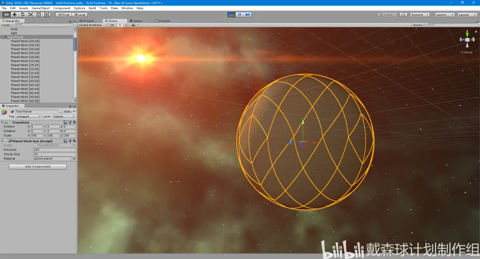
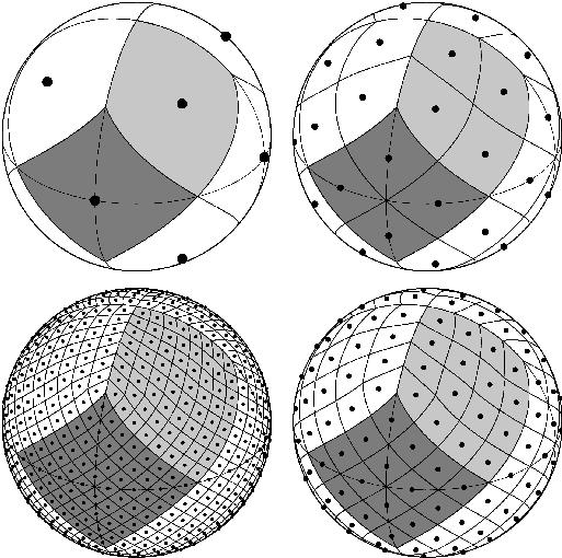
(I create vectors perpendicular to the cube's faces, and assume light bleeds across from the face in that direction, perpendicular to that face)
the anisotropy is just 1/(1 + [float] * dot(view direction, sun direction)) where [float] is between 0 and 1, closer to 1 for stronger anisotropy.
The backside (viewer facing light source) looks good but from the perspective of the light source, the cube has extremely high reflectivity. It's a white panel looking in from the front.
fair, that's fairly easy to change since it's just multiplying the diffuse brightness by something
That looks real good, a strong base to start with for sure
the main thing is just figuring out what you want to exponentiate to get your output color
Hey, how can I make the vertex colors sharp ?
This is what I have now, I want to remove that blending between these colors


maybe rounding could do the trick then its either 0 or one for each color channel
@knotty juniper I have tried that, it corrupts the color
I think there should be more math behind
Does anyone have any idea why my normal maps are completely wrong? I have been trying to render a normal from a highpoly to a low poly the entire day and every single attempt comes out broken in some way or another.
- the texture type is normal map
- the shader is just the normal plugged directly into the normal
- the mesh is all one smoothing group, exported from 3dsmax, where I also do the normal bake


put it through a step function perhaps
the baked normal map file itself looks more or less normal correct

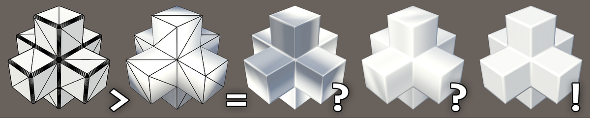
Medium
And how to tell what’s wrong with your content pipeline.
I followed this guide letter by letter and I cant get the normal to not be completely fucked
im at my wits end and cannot find a single thing im doing wrong or single tyhing to do differently, but the output is complete garbage
there is also a weird square grid on it tyhat you can only see from very sepcific angles

do you have a test mesh that i can use for testing
(i cant seem to be able to find any vertex colord meshes in my test project)
@knotty juniper I am using Polybrush for the Vertex painting
good idea let met test that
I think, I need to calculate somehow the other vertices to get the correct color value, or am I wrong?
Converting color space from Linear to RGB makes it less blurry, but this is not exactly the thing I want to achieve
mmm just rounding works fine for my value test

so you want some non solid R or G or B value to have hard cuts
Yes, exactly
is your transition always to black or do multible vertex colors mix?
Multiple colors
makes it kind of difficult
And if it would always transition to black, how would it look like ? Or what should I do
i would generate a mask from the vertex color
this could result in somting like this

you get a sharp mask for the transition between black and any other color
Anyone know why this doesn't work? I'm running Unity 2020.3.5f1 on URP, if that helps at all. I haven't changed this shader at all since I started creating it and it's just not working, so I'd really appreciate some help. This is the first shader I've tried working on in the Shader Graph (and in general) so my only understanding of shaders comes from limited experience in Blender.

im not quiet there yet but this is my result so far

its allows for selecting 3 colors for masking so far
This is interesting, but is the masking high on performance cost?
probably not
still needs some work
the black lines should not be there
this is currenty how i get the mask for each layer

dang i forgot that the color mask node exist
Shaders will appear pink if they do not match the active render pipeline
To fully use URP make sure you've fully completed its configuration process
https://docs.unity3d.com/Packages/com.unity.render-pipelines.universal@12.1/manual/InstallURPIntoAProject.html
Or alternatively create the project from an URP template in the Hub
Thanks, that explains it.
Hey guys, I added a material generated from an unlit shader graph onto my image, and it just turns maroon red

Im kinda new to shaders so I have no idea where to even start looking.
Im using the builtin render pipeline btw
are you sure that the UI provides Propper uv's?
wdym?
Whats weird is that it looks fine in the scene

Oh wait.
I think I know why.

@potent jetty i gone some solution not sure if it works for you
Black is the background color when no texcture is selected

only 3 colors so far but you can expand it
@knotty juniper Thanks man, I will look into it : )
hey, I've got something I'm going to program but i just want to check that it would actually work before i do it
i'm processing lots of "particles" on the GPU (not as in the particle system or VFX) and i need to get the bounding box of them all. can i have a value which all the instances can write to, setting the maximum and minimum of the particle position based on the currently processed particle?
maxPos.x = max(maxPos.x, particlePos.x);
something like that
would the threads ever interfere with one another, and if so, would it be more or less negligible? (I can probably still work with a close approximation of their bounding box)
thanks but I am so new in unity that I really don't know these stuffs, is there any tutorial I can learn from, sorry for being so noob
Yes they would, no it wouldn't be negligible.
Use ATOMIC operations, perhaps in group shared memory.
A few things to google-search about.
https://microsoft.github.io/DirectX-Specs/d3d/HLSL_SM_6_6_Int64_and_Float_Atomics.html (Unity isn't going to support/guarantee 6.6 operations, but reading this will tell you about uints).
For using ints (pre 6.6), "just" multiply the floating point values you have by some scale factor such as 10,000 and take an int. uint would not be able to store negatives.
https://docs.microsoft.com/en-us/windows/win32/direct3dhlsl/interlockedmax
Performs a guaranteed atomic max.
Since as far as I know it's fine to have branches within a shader as long as their constant does that mean I can have use a boolean to allow both specular and metallic workflows within the same shader? And even if different materials use different workflows it'll be fine?
You're better off using a shader variant. The two types are decided at compile time, making two variants in your example (specular or not-specular aka metallic).
Oh I'm unfamiliar with shader variants, I'm currently using URP so i'll look into it rn
Thank you for the tip
wow, thank you so much!
Anyone know how I could have a stencil like effect, but blur the edges of the stencil mask?
depends on how you use the stancel mask
you could use the mask to render a mask texture
then run a blur pass over that and use that for whatever you need
Is there something i can get for visual studio code to autofill .shader files?
Yup
Community version?
it's supposed to support shader & hlsl editing
I do not think vscode support it at all
I have visual studio
hey guys, is there such a thing as in-shader culling
specifically talking about geometry and tessellation stages ?
I'm looking into ways to make performance of a geometry grass shader better
I'm trying to make a shader for wavy grass with shader graph in hdrp. My grass quads look good when lit but when I can see the "dark" side of the quad it looks terrible. I followed this brackey guide https://youtu.be/L_Bzcw9tqTc
Is there anything I can do to light both sides of the quad or maybe somehow cull the quad if dark?
Or will this method for grass on quads just not work with realistic lighting?
Hey everyone I am trying to apply blurry effect in unity basically when i start the scene everything should be clear resolution but when I move with mouse rotation my scene should start blurring
i am running a smple shader script for blur
but when i run it all i see is a gray screen
can anyone help?
maybe you blurred too hard
btw make your MKV into an MP4. Discord supports embedded MP4s
I'm trying to follow along a video, but my verts seem to just stretch into infinity, and I'm quite confused on why. I have an extremely simple setup. The UVS on my mesh were reset to make every face take up the whole uv space


no i only used shader
how do I clamp the UVs the shader is reading to just that one sprite in my sprite atlas?

add to your UV a Vector2 of which sprite you want to access (as in (0,0) or (1,2) etc.) then divide that sum by however many sprites wide your atlas is.
so if your atlas is 8x8 sprites and you want to access the sprite 4th from the left and 3rd from the bottom, you would do (UV + (3, 2))/8
and it's (3, 2) and not (4, 3) because the index would start at (0, 0)
hopefully i haven't screwed that up, lmk if it works