
#A4T-C - Tool Changer A4T
1840 messages · Page 2 of 2 (latest)
 agile pelican
also i found out that for printers like voron 2.4 with flying gantry this design needs door buffer/extension for the 2020 aluminium profile so it wont block the z tension idlers to move all the way up, so for voron 2.4 it ill probably need door extension like this from stealtchanger https://stealthchanger.com/hardware/door_buffer/

 valid turtle
Could you not integrate the horizontal bar into the front Z joints? Seen something like that for the MadMax once
agile pelican
valid turtle
Could you not integrate the horizontal bar into the front Z joints? Seen somethi...
i dont think it will work
 tawdry sleet
Hi @sturdy gazelle can I get added to the testing list, I have a mercury 1 hydra, full metal gantry, awd printer with a4t toolhead, a personal mix of 5-6 projects 🙂 and I'd like to add one more, I was planning to adapt medusa hc to my build, but this looks like a better solution because I can keep my xol carriage and switch single/multi extruder if I need to.
I've built and tried 7-8 toolhead designs (front mounted and top mounted rails) and A4T is my favorite
Other than the mounting points for the docks I won't need to change anything to fit my build (and given that mercury one has a higher gantry than trident, this makes is better because the hotend fan is above the front frame)
 molten wasp
agile pelican
also i found out that for printers like voron 2.4 with flying gantry this design...
Or a new build using 4040v and 2040 extrusion
agile pelican
molten wasp
Or a new build using 4040v and 2040 extrusion
i have jst built it with the 2020, lol but i jst installed the doorbuffer so it will bw fine
 potent imp
I am itching to print out a tool holder assembly!
I was just looking at the new sovol and that is exactly how it works also. Im not a huge fan though, I would have rather seen a servo.
 gritty ridge
potent imp
I was just looking at the new sovol and that is exactly how it works also. Im no...
Why do you prefer a servo?
If you are referring to how extruder arm is opened (for toolchanges) then most of these methods (even ones that use a servo) use the extruder stepper to open the gears up. The servo isn't doing that except for maybe the EMNA toolchanger. Instead the servo is used to engage a gear onto the stepper which has a cam or eccentric lobe to push the arm open.
Some toolchangers that use stepper motor in this way use a mechanical method to enable the gear rather than a servo
 wintry hazel
I still would love to see someone explore using a remote servo, and a cable/sheath to remotely open/close the extruder. Would move most of the weight off the tool head, and allow for a powerful servo
potent imp
gritty ridge
Why do you prefer a servo?
If you are referring to how extruder arm is opened (...
Anything other than retracting the filament. I am just not a fan of mixing these two functions.
 keen ibex
@sturdy gazelle any new teaser? 😄
 sturdy gazelle
keen ibex
<@792573634706145290> any new teaser? 😄
Not at the moment. I've been in the process of selling a house, moving, and getting my life back together lol. I'll be able to get back on it soon though
Literally just signed the closing documents about 2 hours ago
 proven saddle
A4T-C does pretty much that uses the carriage to open, im not a fan of using a servo, maybe a stepper motor, but i have had bad luck with servos and using them for static load holding for any real time, and as i gather your looking at a rc style servo, the interrupt eats up clock time on the MCU, unless your offloading the servo control to another device.
 cyan barn
Saw this video earlier today about TPU on the M1D. Isn't the same issue applicable for A4T-C as well?
Any Super Early Birds left? Please get your Sovol M1D using our link (Kickstarter) → https://sovol-3d.kckb.me/gergo-uez (or https://gP3D.click/M1D)
This video is a response to the most frequently asked questions under our earlier episodes. Most prominently, we tested the Sovol M1D's capability to print flexible TPU alongside rigid PETG and P...
sturdy gazelle
proven saddle
A4T-C does pretty much that uses the carriage to open, im not a fan of using a s...
I'm working on a revision to the extruder that won't use any external input to open the release lever. So no pin on the dock or servo or anything. It's still a WIP but it's promising.
 carmine lantern
potent imp
Anything other than retracting the filament. I am just not a fan of mixing these...
You typically want to retract the filament anyway when parking the tool so there's no pressurized filament in the nozzle.
 lost ridge
Can't really search the thread at this time, has anyone discussed the possibility of putting the hotend fan in the back?
tawdry sleet
sturdy gazelle
I'm working on a revision to the extruder that won't use any external input to o...
If you look at the design for the feeder on MedusaHC, in my opinion that is a more elegant solution even if it adds a micro servo, compare that to the one from YUDX which, although it relies on the extruder motor it has to add so much mass to the toolhead to allow that motion and it negates the whole benefit of not needing a servo
you can also use that same servo motion to engage a locking pin at the very top of the hotend mount eliminating any vibration due to the bowden tube pulling
carmine lantern
The added mass for the extruder unlock on A4T-C will be minimal - a 1 way bearing and a plastic gear and shaft. If you're looking for a super light weight tool head you're not really looking for a toolchanger - there's always going to be trade-offs
lost ridge
Eventually there will be a sub 10 benchy done by a toolchanger.. Maybe
 cosmic plover
carmine lantern
The added mass for the extruder unlock on A4T-C will be minimal - a 1 way bearin...
Who needs light weight when you can just have moar powah!
carmine lantern
more power doesn't help much with VFAs though - a factor of weight and resonance.
keen ibex
sturdy gazelle
Not at the moment. I've been in the process of selling a house, moving, and gett...
Thank you for the honest reply! Wish you all the best. I hope everything runs well and as you expected it.
tawdry sleet
I've started combining Medusa HC with A4T, very early work, just theoretical so far, this is what I have after 6 obsessive hours of work, I will print it out of PLA to see if everything fits, I chose rapido 2 + sherpa because that's what I have around to test


 cosmic plover
Since it looks like this project is changing direction to a kinematic type mount, this video talks about something we might want to keep in mind.
We think we figured out why our @bondtechab and @Prusa3D INDX prints are coming out so terribly! It all comes down to some loose toolheads that aren’t getting seated properly on their ball bearings. So join us for #PrintFix Friday episode 259 for the start of our journey of getting our INDX Founders Edition printing perfectly - NO MATTER WHAT!...
 modern tulip
cosmic plover
Since it looks like this project is changing direction to a kinematic type mount...
they say you need to lubrate the mount (which tbh is nonsense, I think there are other issues with INDX than that). the tools are kinda floppy and its a steel on aluminum kinematic mount
but kinematic is much preferable to pin based
 toxic pilot
Yeah you see many tools that are not properly aligned. Maybe the upper tensioning/locking lever is not the best option here.
tawdry sleet
I designed a maxwell coupling between the hotend and the carriage, however now I'm thinking it might be too hot there in a heated chamber and I can't find any magnets d12 x 3 or d15 x 3 N42H or N42UH that can handle temperatures higher than 80 degrees
 spice shard
tawdry sleet
I designed a maxwell coupling between the hotend and the carriage, however now I...
Samarium Cobalt or Aluminium Nickel Cobalt.
But if it's uncommon size you may need to have a custom order which usually involves MOQ.
tawdry sleet
that's not really a solution I want it to be built with readily available parts
spice shard
Or good Neodymium magnets, there are classes of those with varying temp resistance.
tawdry sleet
as I see it now I have 3 ways forward:
- look for high temperature resistance magnets
- drop the xol carriage and move the magnets farther back, away from the hotend
- move the maxwell coupling higher up between the hotend and the extruder, it comes with some advantages and some disadvantages, on 1 side I would have space to use thicker magnets and it would eliminate the coupling behind the hotend allowing it to go farther back closed to the carriage, but the toolhead would need to be 10-15mm taller and the coupling point wouldn't be exactly in line with the carriage it would be higher up
 night perch
tawdry sleet
I've started combining Medusa HC with A4T, very early work, just theoretical so ...
This appeals to me. Can’t go wrong with rapido 2 and Sherpa
modern tulip
spice shard
Samarium Cobalt or Aluminium Nickel Cobalt.
N42SH or N52SH are much better than a larger SmCo though in terms of force. @tawdry sleet I would advise the N52SH 6x3 magnets, those are available. also if you seat the balls deeper between the pins you get a higher min displacement load. there has been discussion in monolith about this for ronin
the tangent angle where pins contact matters a lot
spice shard
@idle island has dome some buying on magnets not long ago
the higher heat resistant Neodymium ones
 dim perch
Would having a current A4T make it easier to move to this in the future or is it just as much work?
modern tulip
dim perch
Would having a current A4T make it easier to move to this in the future or is it...
prob not
dim perch
Is the gantry frame even the same?
modern tulip
dim perch
Would having a current A4T make it easier to move to this in the future or is it...
unless you wana get deep into the dev I would wait to see which project wins
modern tulip
dim perch
Is the gantry frame even the same?
well gantry and stuff is the same
carraige changes
there's a ton of projects https://toolchangers.baconmilkshake.com/
A reference for 3D printer toolchanger topologies
dim perch
I guess I meant the carriage. Whatever attaches to the MGN carriage and belts
modern tulip
CXchanger, and yudx have gotten the most attention of late
modern tulip
dim perch
I guess I meant the carriage. Whatever attaches to the MGN carriage and belts
basically everything on the x carraige would need to change
dim perch
I'm actually in those Discords as well
I've quite literally just finished my LDO kit V2.4 with Stealthchanger. I haven't even finished re-printing the parts in ABS. So, probably getting a bit ahead of myself. But a big reason I came down the Voron rabbit hole was tool changing and multicolor/material.
 idle island
spice shard
<@406876419222667264> has dome some buying on magnets not long ago
aye, the cobalt one seems to be better idea for magnet probes like klicky-00, have bunch of them and N52SH rated for 150C directly from factory in China
tawdry sleet
modern tulip
N42SH or N52SH are much better than a larger SmCo though in terms of force. <@21...
You are right d6x3 are a lot more common in SH variant, I ordered 50, in a few minutes I will post some updated design with those magnets
Still a long way to go before I test the design in real life, but now I have a plan


See the issue why 80 degrees regular magnets will 100% die in that location in a heated chamber
modern tulip
tawdry sleet
Still a long way to go before I test the design in real life, but now I have a p...
one thing we round in CXchanger and monolith is that for this sort of extruder kinematic mount you need the kinematic mount to be seated deeply. For CXchanger it could sustain a ton of load (left) because the tangent angle on the intersection is like 15-20 degrees off vertical, so its very hard to unseat from lateral force. But on the madmax style moutning used on ronin (right) its like a 45-50 degree angle, far easier to unseat which caused a lot of problems given the extruder applies significant load to the kinamatic mount.
I would def check the seating angle on those balls on your design

 tawdry sleet
modern tulip
one thing we round in CXchanger and monolith is that for this sort of extruder k...
I understand, thank you for the tip, it makes sense now that you say it, I will need to redesign it, because as is, the angle is very wide and the seating is very shallow, I kept worrying about level force by the cable/bowden tube, but forgot the extruder is actually pushing really hard downwards and that is the biggest force I need to worry

one more thing I'd like to pull from your experience, I came up with the idea to use a steel pipe D4 d2 for the filament path inside the extruder, in my mind this would be best because it would allow very little material to be removed from the extruder for the entrance, but I haven't seen it elsewhere and I don't know if it's a bad idea
 wintry hazel
Steel will wear faster with abrasive filament. And will be harder to manufacture
tawdry sleet
it's just pipe cut down to length, similar to the one used in xol carriage, but I understand the issue with abrasive filaments, I'll keep thinking
wintry hazel
I had wondered if you could cut into a solid PTFE tube, rather than using printed parts near the gear. But that would still require some manufacturing simple printing and cutting tube
tawdry sleet
A lot of extruders use some metal guide at the exit of the gears, so I think in short paths it would be fine, it won't eat away that fast with abrasive filaments
maybe I can use 10mm steel then switch to ptfe for internal path
modern tulip
tawdry sleet
one more thing I'd like to pull from your experience, I came up with the idea to...
its good in principal
its actually what INDX uses
wintry hazel
Only one way to find out! Plus, I would guess most people using the super abrasive filaments, aren’t going to be using this solution
tawdry sleet
@modern tulip did a little math how much attraction force would be needed to keep the coupling locked to counter the extruder especially when clogged
if I'd add so many magnets to counter that force it would be almost impossible to pull away without layer shift
modern tulip
well wait you aren't using induction- you just want to line it?
why not just use ptfe or do what orbiter or the peopoly lancer extruder do, use a brass or other metal filament guide?
tawdry sleet
I think kinematic coupling is a bad path
modern tulip
tawdry sleet
<@735335527993311243> did a little math how much attraction force would be neede...
are you calculating based on pull off force which is much higher- or sliding force off the slope?
modern tulip
tawdry sleet
I think kinematic coupling is a bad path
if you do not have kinematic its very hard to get your tool mounting position reproducible
and still easy to swap
tawdry sleet
modern tulip
well wait you aren't using induction- you just want to line it?
why not just us...
I was relying on the idea that you need very little steel to keep it straight
modern tulip
tawdry sleet
I was relying on the idea that you need very little steel to keep it straight
you could get closer since you can do a fine tip like they do on orbiter
tawdry sleet
for ptfe you would also need a printed case around it
modern tulip
you could prob just buy the orbiter filament guides
if you were gonna do this
tbh the filament path on these filament swappers is rough in general
indx has some issues
I recently saw it bend up PLA like it was tpu

 midnight latch
modern tulip
one thing we round in CXchanger and monolith is that for this sort of extruder k...
"Caused a lot of problems" is an overstatement for something where there's approx zero printing printers here. It's a concern and it's an area for more test. The style can support a steeper interface angle, but that requires (trivial) changes to the current design. Is it steep enough? Unclear. And there are other ways to handle this, like twisting the bottom of the coupling about X.
modern tulip
midnight latch
"Caused a lot of problems" is an overstatement for something where there's appro...
thats fair, mea culpa- it was an overstantement. Though the fact that the displacement force on the original ronin design was only 2kg lateral would absolutely fail if one tried to use the version that existed last week. I more mention it because it does seem to be an element that one needs to be very cognizant of with this sort of filament path swapping toolchanger
tawdry sleet
this was my thinking behind the steel pipe, you would need very little material, but now that I consider the force of the extruder pushing down ... that is no longer true, you need a lot more plastic to combat that force
 midnight latch
modern tulip
thats fair, mea culpa- it was an overstantement. Though the fact that the displa...
Yeah, I agree. We all missed it as a concern early. I think it's addressable but the Q is whether BHCS support enough interface angle in practice for a solid-enough grip.
modern tulip
midnight latch
Yeah, I agree. We all missed it as a concern early. I think it's addressable b...
honestly I was shocked because I was so confident that the original ronin kinematic would be way better with the madmax magnet optimizations and bigger pins. was very easy to miss the effect contact angle has.
I def think its addressable but yeah I think bhcs will be hard. though there does seem to be a few other options that are not too painful to source
I really want to get rid of that eyebolt personally
tawdry sleet
how would you stop the extruder to create a lever on the coupling, I'm out of ideas, it is a lot stronger than any force, 5-6 even 10 kg force and even though it is in the same plane as the coupling it is offset by a few mm
adding 2 pins would solve that but it would defeat the whole purpose of the coupling with precise alignment
tawdry sleet
just a though, it may be a dumb idea but I'm thinking of the kelvin coupling where you can mix different shapes as long as you prevent movement in all axis, I can keep the 120 degree distribution, but replace 1 ball and groove with 1 single pin, this would allow that pin to dictate the Z axis and the other 2 balls and grooves would precisely align the X and Y, because rotational movement would be allowed by that pin
tawdry sleet
would something like this work? 1 d3x12mm steel dowel pin entering in a steel D5 d3 pipe to lock the coupling on Z axis and prevent the extruder and the cable+bowden from creating a lever on the Z axis and 2 ball and groove pairs at 120 degrees to precisely lock it in on X and Y
what am I not seeing?


hmm it's overconstrained on Y it's not good enough
 shrewd surge
modern tulip
thats fair, mea culpa- it was an overstantement. Though the fact that the displa...
Ronin is still a work in progress with exactly zero working toolheads build. The Github repo makes it pretty clear that the design is a work in progress and you should not be building one just yet!

I'm not a mechanical/hardware engineer, because of that I make mistakes others wouldn't but I'm learning and the community has been an awesome resource to learn from so far!
shrewd surge
tawdry sleet
would something like this work? 1 d3x12mm steel dowel pin entering in a steel D5...
That would only work if the pin that holds z in place has a very very tight tolerance on the bushing. Any movement in z during printing is gonna show up as a print artifact
tawdry sleet
that's why I was thinking steel on steel, both precisely 3mm with a chamfer to ease the alignment
I understand now why no hotend changers use purely kinetic coupling, fighting the extruder's force makes it quite difficult
if you make it strong enough to stop the extruder, it will be so strong it will be hard to pull apart
shrewd surge
tawdry sleet
if you make it strong enough to stop the extruder, it will be so strong it will ...
Those scenarios are two different forces acting on two different axis. Extruder exerts a strong force in Z, while docking has forces on the Y axis.
You'd just need to design a mechanism that resists z forces but has a tuned force on Y so that the xy motors can pull the tool of the toolhead. Cxchanger does a pretty good job there
tawdry sleet
shrewd surge
Those scenarios are two different forces acting on two different axis. Extruder ...
That makes it worse, because the magnets are stronger on Y than on Z with this positioning
the only way to counter the Z push from the extruder is with pins, also the hotend holder needs a lot of plastic to prevent bending between the extruder and the hotend
shrewd surge
tawdry sleet
That makes it worse, because the magnets are stronger on Y than on Z with this p...
Not really, a well designed maxwell coupling, like cxchanger, resists forces in z. Video is from the og creator of cxchanger
But i dont want to clog up this project thread more then i already have haha 
sturdy gazelle
Lots of interesting chit chat going on here since I've been away...
As soon as my son gets his apartment I'll be able to get my office set back up and get back to work on this project. Sorry for the delay.
cyan barn
sturdy gazelle
Lots of interesting chit chat going on here since I've been away...
As soon as ...
Everyone's neurons are firing at high speed here 😄 . Take your time
sturdy gazelle
cyan barn
Everyone's neurons are firing at high speed here 😄 . Take your time
I see that lol.
modern tulip
tawdry sleet
just a though, it may be a dumb idea but I'm thinking of the kelvin coupling whe...
kelvin is harder than maxwell to do in practice
modern tulip
tawdry sleet
would something like this work? 1 d3x12mm steel dowel pin entering in a steel D5...
this is not kinematic since you are limited to the tolerance of the pin.
tawdry sleet
yes I gave up on the plan 🙂 I learned something from the cxchanger project, their maxwell coupling has some real improvements
sturdy gazelle
A Maxwell coupling is possible on my design, and it's likely I'll be going that direction. I just need my office back so I can finish it lol
 viscid vale
I'm just rehashing what's already been said here, but I'll include a drawing at least. With a maxwell coupling the relationship between how much attractive force you need and how much resistive force against the Z axis you need will be the key. The shallower your ramp angle, the less attractive force you need.
It will certainly be possible to tune this in a way where pulling away from the magnets when undocking a tool will not cause layer shifts, while resisting extrusion forces. The angle required is not really known yet, although CXChanger uses an angle of 29.7 degrees. That makes the ramp angle roughly 15 degrees.

There's no reason we couldn't even cut that angle in half, and still have an effective maxwell coupling. Although it would require more precision in manufacturing as there would be less tolerance before your pin might not make contact with both sides of the groove.

For reference, here's the version I tested that could only resist ~2.1kg of downward "extrusion" force. You can see why this did not work, but it's a solvable (solved?) issue.

 pure silo
viscid vale
I'm just rehashing what's already been said here, but I'll include a drawing at ...
This is the direction I took for Dragons Den and so far it has been solid as it gets. Very similar concept to the maxwell joint, opposing pins 120deg offset, except instead of a ball seating against the pins, I am using 3 pins that slide in between the other pins. Tolerance is critical though and the spacing between pins cannot be too tight or too loose, but the toolhead is completely held in place and cannot move at all except to slide in and out. It is also completely self aligning.


 next rivet
Really cool project!
Any thoughts made on integrating a load cell in the holder somehow?
Really interresting stuff about pressure advance calibration using a loadcell on youtube recently.
spice shard
next rivet
Really cool project!
Any thoughts made on integrating a load cell in the holder ...
Let's not scope creep too much just yet 😄
 mystic quiver
spice shard
Let's not scope creep too much just yet 😄

carmine lantern
spice shard
Let's not scope creep too much just yet 😄
The Best Time to throw out ideas is before the design is too far along and getting useful bits added become more complex
cyan barn
What's happening with the project? Its been quiet for a week
carmine lantern
Slimohan moved so he's still unpacking I think
sturdy gazelle
cyan barn
What's happening with the project? Its been quiet for a week
Yeah, still getting settled in the new house. And unfortunately my spawn is still staying with us temporarily until he gets an apartment, so my office is taken until then.
cyan barn
sturdy gazelle
Yeah, still getting settled in the new house. And unfortunately my spawn is stil...
Oh I know you are busy. Take your time.
Just surprised to see all the other conversations in here sudden went silent.
carmine lantern
I finally made some progress on my Trident 300 though - got most of the wiring complete, firmware for Manta, H36 and carto installed, cfg files created and tweaked for my setup, and basic homing, motion and bed leveling working.
 mortal locust
carmine lantern
I finally made some progress on my Trident 300 though - got most of the wiring c...

Patiently waiting 🙂

 cobalt musk
mortal locust
Patiently waiting 🙂
Purple frame is something else .
Looks so sick .
Congrats
carmine lantern
But will be very tricky to color match for a rigid door or top hat if you're adding a toolchanger
I have a LDO red Trident 250 that getting pieces for a rigid door is almost impossible
 slow helm
With a Trident LDO 300 kit, how much build area would remain for a project like this?
I’m still undecided whether to get an LDO 300 kit or build a frame myself with 350x350 and a Z-height of 300.
 versed path
slow helm
With a Trident LDO 300 kit, how much build area would remain for a project like ...
if you can ask formbot for 350 kit without the bed and buy 300mm bed would be better
carmine lantern
I think It's estimated to take up about 35mm of the Y motion on a Trident. I'm considering modding my front idlers and using longer Y rails since I'm going to use a rigid door that adds extra space at the front - it's only something like 10mm extra though, unless I put the window on the outside
slow helm
Okay, I think I'll actually build one with 350x350 and a Z-axis of 300.
potent imp
wouldn't it be better to have a bed that is 50mm bigger? Then you have more thermal mass and you dont have to worry about putting the build plate on straight. I use build plates that are 20mm larger at the minimum.
pure silo
potent imp
wouldn't it be better to have a bed that is 50mm bigger? Then you have more ther...
It depends. Having the bed bigger means you are less likely to be able to reach off the sides of the bed, so you wouldn't be able to have a nozzle brush, or alignment probe off the edge.
But everyone likes their printer set up differently to everyone else so it's entirely up to how you want yours to be
carmine lantern
pure silo
It depends. Having the bed bigger means you are less likely to be able to reach ...
You can but it'll need to be on a servo so it swings into and out of the print area
slow helm
https://www.printables.com/model/1468363-nozzle-cleaner-voron-trident/comments
If you use something like that, you don't need a servo and can utilize the maximum bed size, right?

Printables.com
Designed this Nozzle Cleaner Mount for my Voron Trident | Download free 3D printable STL models
carmine lantern
Well, no. If your bed is oversized then your nozzle doesn't clear the edges of the bed and can't reach the brush
 storm hinge
Oh... with trident r2 + indx comptible bed mounts I can put something like this up front. 😁
slow helm
@carmine lantern : I don't quite understand. Why is my bed oversized?
carmine lantern
I guess you missed the conversation about oversized beds directly above that my servo comment was a reply to?
slow helm
Yes, I missed it
@carmine lantern :
Would you build a Trident with a 300x300 bed and 300mm Z-height, or 350x350 and 300mm Z-height? In any case, it has to be a toolchanger
carmine lantern
I'm building 300x3 Trident if that answers your question. 😉
Personally I feel that the 2.4 is a better option at 350 due to the larger and heavier bed
pure silo
carmine lantern
Personally I feel that the 2.4 is a better option at 350 due to the larger and h...
I have a 300 trident and 350 2.4, I must say, I prefer my trident over the 2.4, but I do have aluminium gantry plates on the teident, so maybe that skews it haha. The 2.4 will be getting AtinyShellScript plates soon.
 random geode
i have a 250 trident and i built a 300 2.4 - took the 2.4 apart and decomissioned it before i bothered to serial it
carmine lantern
There's a lot more moving parts to wiggle loose with a 2.4 but for larger prints having the bed static is a benefit I think. Anyway, both work very well so make the one you prefer
slow helm
 potent imp
slow helm
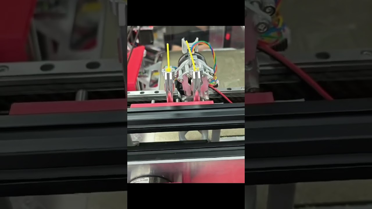
https://youtube.com/shorts/WFxnBoCGgj4?is=ZOJ2qPxHV8c5Y32N
I search for more info on the product a few days ago, I could not find anything.
proven saddle
Same they have been teasing this for awhile with no info
 pearl tundra
Hey, where can I get the files?
random geode
pearl tundra
Hey, where can I get the files?
you cant - its not out yet
 elfin ice
Maybe a preliminary BOM so we can get prepared 🙂
carmine lantern
V1 is mostly a proof of concept I think - there's a bunch of changes for V2 that significantly change the bom
lost ridge
8 dragon ace volcanoes probably
carmine lantern
I think using a bambu hotend is the intent just to keep the cost down
at least as the default design
 candid edge
Will rapido be supported too I hope
 urban solar
I hope there are plans for other hotends. The bambu mount in printed toolheads kind of sucks. TZ v6 2.0 would be a better low cost option
tawdry sleet
If anyone has time to do a quick review, next week I will print the parts out and test it fully, until now I tested parts of it, like the extruder hotend mount and maxwell coupling.
Disclaimer: this is my own interpretation of A4T hotend changer, I tried to learn from Medusa HC and cxchanger and bring the A4T flavor
consider this pre-alpha don't try to use it, it hasn't been tested.
It uses LGX Steel Drive Train + nema14 10T motor, Rapido 2 HF, Carto v4, BTT EBB36 and the dock is calibrated for Mercury One FMG AWD, In theory you could fit up to 8 hotends on this printer, but that seems overkill
Once everything is tested I will make the whole printer design public and free, but pretty much everything will be compatible with Trident or Trident inspired printers
 dusty plover
tawdry sleet
If anyone has time to do a quick review, next week I will print the parts out an...
I just cancelled my indx order and am aching for a new solution so I might give this a go. I gave the CAD an overview and like what’s there so far. I’ll probably try with a dragon ace as I have one on hand and see if I can just get that printing. I’ll order some parts tonight. My only concern is routing hotend wires through the front as some of those runs seem hard. I might adapt for a Bambu style hotend that I have as well since those have pretty flexible cables.
gritty ridge
dusty plover
I just cancelled my indx order and am aching for a new solution so I might give ...
What type of printer are you wanting to add a toolchanger to?
dusty plover
gritty ridge
What type of printer are you wanting to add a toolchanger to?
I’ve got both a 2.4 and a custom machine. The custom has 3 madmax heads in the front and I designed it with enough overtravel to have a full 250 trident bed that the heads can completely access. I’m going to leave the custom alone for now but if there’s a good horned changer I might swap to it. I’m targeting the 2.4 as I’d like to try for 5 or even 6 tools.
gritty ridge
dusty plover
I’ve got both a 2.4 and a custom machine. The custom has 3 madmax heads in the f...
That custom sounds pretty nice and your adjustment to still be able to use full bed sounds great! Have you considered any of the other hotend toolchangers to replace the INDX you were planning?
dusty plover
I’m here as I’ve been paying attention to the A4T-C development but I’ve been finding any cad that I can. I’ve also been looking at the Medusa hc and the cxchanger. The Euryale was also posted in boron mods recently but that seems more like a revision in the cxchanger and I don’t like wrapping around the beam on vorons. I figure trying a few doesn’t hurt as I can build it and maybe try 2 tools before committing. I’d still like to see the A4T-C completed but since I’m sitting around anyways I figure why not run off what I can find. The madmax on my custom build has been running really nicely but it gets annoying building a whole tool head to add another tool. I’ve explored stealthchanger and while it’s a good system I’m trying to take up as little space in the 2.4 as I can. INDX would probably have been ideal but after seeing some of the coils get caught in a blob of death I decided to wait and buy again once I’m confident. It was too expensive for me to feel uneasy about having a failure.
If there’s others you’re aware of I’d appreciate any info.
gritty ridge
dusty plover
I’m here as I’ve been paying attention to the A4T-C development but I’ve been fi...
Yeah, for sure. I agree about doing just a couple of tools at a time as scaling up should be easy once you get the first ones dialed in.
There are a few but given you're interested in adapting to 2.4 I am always curious about how the tools will dock into their bays. The one hotend changer that I think solves this issue really well is the Lineux HotSwap. Its now in open beta. I think current beta test group have it running on VzBot, Voron 2.4 and Voron Trident but do not know for sure.
I can send you more info if you're interested
dusty plover
Thanks for pointing that out. I’ve been stalking the lineux discord for a few months and saw the video of it. I’m hoping to retain the front mgn12 and keep the front mounting tool style. My recollection on the hot swap is it used something like the cxchanger where a pin pried the extruder open. The filament path was also a bit longer than others.
Funny enough I have a vzbot which would play well but since I’ve got the aluminum tool head and space feels more restricted (no overtravel) my plan is to leave it and integrate the box turtle I run on my 2.4 as well as a 3kg night owl mod I’ve been assembling.
tawdry sleet
dusty plover
I just cancelled my indx order and am aching for a new solution so I might give ...
there is plenty of room even for rapido's thick cables, I just printed everything out of PLA, I will upload some photos, I have made some small changes I will give you the new CAD


you can see in the last photo, you can easily fit 2 more cables if need be, I want to also add a 5V LED in parallel with the fan, to maintain the look and feel of the A4T, it's hard to have it addresable RGB, but a simple LED or a blinking LED would be easy if it's 5V like the fan
I Improved the cable routing in the hotend, removed some plastic and added more where it felt thin, fixed the dock's orrientation (dock is very much WIP)
I need to come up with a way of supporting the upper part of the fan mount, it's impossible to print it without supports even out of PLA with strong cooling
dusty plover
Thanks for confirming, and unfortunately supports are probably needed. As I've seen these toolheads get more complex the geometry just needs it.
I'm remixing the previous one a bit to fit some spare hardware I have and am ordering some of the parts I don't. I'll probably also run off a PLA prototype in the next few days. I'm hoping the rounded 4mm pegs I sourced are reliable, I don't know if you have a suggested retailer.
tawdry sleet
I still don't have the rounded pins, I odered them 3 weeks ago, they are hard to find, so I will most likely remix that for a very common of the shelf solution: stainless steel piercings 😆
I ordered 10 barbell piercings, they have 2 stainless steel 4mm balls bound together with a 10mm double headed screw, so the plan is to cut that screw in half and basically have 2 steel balls with a 5mm M1.6 threaded screw that can be easily locked in plastic
dusty plover
good thing I have those in bulk already 😛
tawdry sleet
😀
they are a lot more common then spherical rounded pins ... at least in Europe, and for 1 euro you get 2 balls and 2 screws
gritty ridge
tawdry sleet
Great pics of your design. Nice to see it printed out rather than something only in CAD. I'm a big believer in prototyping and testing. I can see some really nice design elements that you've incorporated. Well done!
What are the "rounded pins" for that you mention in the following post?
tawdry sleet
these, they are needed for the maxwell coupling, you can't really convince a regular steel bearing ball to stay in plastic, these are bullet shaped balls basically

I ordered these from aliexpress 3 weeks ago but are still in transit, I also ordered a few of these to see which work better, these will arrive today or tomorrow, I ordered them locally

 gritty ridge
tawdry sleet
I ordered these from aliexpress 3 weeks ago but are still in transit, I also ord...
Ah, I see. And now I also understand what you meant about the piercings. Clever idea. Hopefully it may work. I like that you're thinking of ideas and trying them out in actual tests.
potent imp
Piercings. What a great idea. Good job
tawdry sleet
After printing the parts in ABS, I learned a few things:
- Piercing balls offer much better quality than rounded dowel pins. They are perfect spheres, just as good as bearing balls, and with a drop of glue, they are permanently set—you have to break the plastic to remove them.
- Cold pressing magnets is not a good idea when aiming for 0.3mm tolerances. I will increase the hole size and rely on glue to keep them in place, adjusting the gap between them to 0.5mm. CA glue bonds to them extremely well; I actually had to throw away a few magnets because they were permanently encased in plastic.
- The Maxwell coupling (aside from the magnet spacing issue) is incredibly strong. You are more likely to break the plastic part than to accidentally dislodge it.
- ABS won't be durable enough for long-term use. Because the design leaves too little material in some parts for structural integrity, reinforced filaments like PC-CF or PA-CF will be necessary.
Printed in ABS (6 walls, 20% infill with extra reinforcements in some small parts) with everything mounted (except the Xol carriage and Carto V4), the complete toolhead weighs 210g. On top of that 1 hotend assembly with Rapido 2 HF come in at 78g so it will be a decently light design for a multi hotend
dusty plover
These are 4mm, right? What size is the thread?
potent imp
tawdry sleet
After printing the parts in ABS, I learned a few things:
1. Piercing balls offe...
Im not sure CA glue is a good long term solution. It makes abs brittle
For that part that gets shocked all the time, I think two part epoxy would be a better choice since it does not make the plastic brittle.
 tired glacier
The glue should be 100% dry before installing and only on the inside of the ball/on the threads, not touching any plastic. Should be safe to use.
gritty ridge
potent imp
For that part that gets shocked all the time, I think two part epoxy would be a ...
I've not heard that before: that CA is not good for ABS printed parts. I've heard that Loctite can have that effect on ABS
I've used CA with my ABS printed toolchanger for half a year and haven't seen any negative effects thus far
Is it possible you may have those two mixed up? I'd be interested in getting more details on this
urban solar
gritty ridge
I've used CA with my ABS printed toolchanger for half a year and haven't seen an...
Same, I've used CA with asa and never seen brittleness
tired glacier
Either way, it wouldn't be touching any plastic if applied correctly
potent imp
gritty ridge
I've not heard that before: that CA is not good for ABS printed parts. I've hear...
Negative. CA is certainly not good. Loctite, is made of CA. Any place I have gotten CA or Loctite, or anything that smells like CA on ABS/ASA , it has cracked over time. I was under the impression that it was going to lock it into the plastic. So yeah, if it is just locking threads metal to metal, its just fine and dandy.
tawdry sleet
New day, new lessons learned:
- One pair of touching magnets exerts significantly more force than two pairs separated by a ~0.5mm gap. Because of this steep drop in magnetic pull, self-alignment fails with the current design at that distance.
- I initially based my Maxwell coupler on the cxchanger, assuming it was a proven concept. I now strongly doubt its true kinematic effectiveness, at least given the dimensional tolerances inherent to 3D-printed plastic.
- After physical testing, I finally understand why the spheres are seated so deeply into the V-grooves in that design. They essentially act as standard alignment pins rather than forming a true kinematic coupling.
With these print tolerances, preventing the magnets from touching is almost impossible. When they touch, they introduce an overconstraint that completely negates the kinematic coupling mechanism. It's time to go back to the drawing board.
gritty ridge
potent imp
Negative. CA is certainly not good. Loctite, is made of CA. Any place I have...
Okay, thanks for replying. I have not had negative experiences with CA (cyanoacrylate) with ABS so will continue with what work for me. It is my understanding that loctite (red, blue) thread locker is not CA.
gritty ridge
tawdry sleet
New day, new lessons learned:
- One pair of touching magnets exerts significan...
Interesting. What magnets did you use. Dimensions and quantity? I use a very similar Maxwell coupling and find it very effective. Based on videos on Bilibili I have seen several tool changers based on CxChanger and they seem highly effective. Some have slightly different Maxwell implementations (magnets certainly).
I feel that these can be very effective and true kinematic couplings
tawdry sleet
I use d6x3mm n52, the issue are not the magnets, the issue is the positioning, where the top magnet stays outside of the triangle defined by the 3 balls and grove, that means if the distance is higher than 0.4-0.5mm it will be stronger then the other 2 and shift the plane towards it, that's true even if you had magnets strong enough to lift a car
on the other hand if you try to align them at 0.2-0.3mm, building that out of 3d printed plastic with cold pressed magnets and balls is impossible, 0.1mm difference in alignment of any of the balls, pins or magnets would shift the plane enough to create additional points of contact, breaking the true kinematic coupling
but I think my mathematical approach is to idealistic
gritty ridge
tawdry sleet
I use d6x3mm n52, the issue are not the magnets, the issue is the positioning, w...
Sorry, I am not understanding “shift the plane”. I can’t form a mental picture or model unfortunately
tawdry sleet
this is the hotend mount

at 0.5mm 2 pairs of magnets (any magnet) are weaker than 1 pair touching, that means the top magnet which is not in between the 3 balls will fight the other 2, that means the pressure on the 3 balls won't be equal
gritty ridge
I’ve done a lot of experimenting with hotend toolchangers. Many pitfalls, failures, broken parts, repaired parts, reworked designs etc. So it’s great to see you are doing something similar and building actual prototypes to test and review
tawdry sleet
this issue doesn't make it impossible, I just need to reposition the magnets and coupling pairs to distribute the forces evenly
gritty ridge
tawdry sleet
at 0.5mm 2 pairs of magnets (any magnet) are weaker than 1 pair touching, that m...
You may be right that it may not be equal, but in my tests they have proven to be fairly effective. In real world print tests. At least for me with my prototypes
tawdry sleet
gritty ridge
You may be right that it may not be equal, but in my tests they have proven to b...
it works, I built the original part based on the tolerances from cxchanger, but it's not a kinematic coupling
the balls and pins act like regular alignment pins
it feels insanely strong, and you can't feel any wiggle to the touch ... but the alignment will never be mathematically perfect because unavoidably there will be extra contact points
gritty ridge
tawdry sleet
it works, I built the original part based on the tolerances from cxchanger, but ...
If they guarantee 6 points of contact to constrain the two halves, and you achieve repeatability, whether you call it “alignment pins” or something else, isn’t that what matters?
tawdry sleet
but you can't be sure they touch in 6 points, if 1 magnet touches that will define the plane of contact pulling the ball just enough from 1 edge of the groove to allow some difference that will make the coupling nonrepeatable
but that is just in my head 🙂 the reality is that differences may be less than 0.01mm 🙂
gritty ridge
tawdry sleet
but you can't be sure they touch in 6 points, if 1 magnet touches that will defi...
If you describe a scenario known to cause failure then yes…it wouldn’t work. So approach it differently. Don’t let the magnets touch and then that scenario doesn’t happen
These magnets don’t exert any significant lateral pull. Instead they are trying to pull the Maxwell spheres into the Maxwell grooves
tawdry sleet
if you look at the hotend mount, I have a clear triangle defined there in the middle I will use it to position all 3 balls and groove on the edges at 120 degrees, and the magnets forming another triangle inverted at 120 degrees as well
this will allow more room for error and will allow all 3 magnets to be pressed at once in the exact same plane
tawdry sleet
gritty ridge
These magnets don’t exert any significant lateral pull. Instead they are trying ...
that's true, but aligning all 6 magnets in the exact same plane is very hard, that's why I was saying 0.1mm difference breaks everything
gritty ridge
Because you have printed out the parts. Have you had the chance to test them in an actual print? If so, and you observed this phenomenon then it sounds like you have a plan to adjust and retest.
If you haven’t tested and reviewed the empirical findings, you may be missing out on learning practical and useful information that you can use on your next iteration?
As I said earlier, I admire that you have taken the time to print out prototype parts that you can hold in your hands and review in the real world
tawdry sleet
I have printed them, they were very strong and seemed "glued" together, but I could feel small movement at the nozzle level when pushing by hand, and I pinpointed that to the top magnets touching
then on the 2nd iteration I increased the distance between them and that caused the plane shift
gritty ridge
I look forward to seeing more of your work and where you go with it. It may take several iterations but once you’ve adjusted and fix the issues you are seeing, I am optimistic your design will work
tawdry sleet
I still have some open issues, but the coupling is 1st to deal with
gritty ridge
tawdry sleet
I still have some open issues, but the coupling is 1st to deal with
You can try stronger attraction. It really does make a surprising difference
tawdry sleet
I can add 1 more magnet or even 2, but then docking will be hard
gritty ridge
Also, it would be helpful to set up a test jig of sorts to be able to quantify the repeatability. It’s pretty fast to do with a camera
tawdry sleet
this is my curent docking mount ... I hate it, that angled pin ruins it for me, even if it would work 😂

 gritty ridge
tawdry sleet
this is my curent docking mount ... I hate it, that angled pin ruins it for me, ...
I’m guessing that angle is necessary due to some physical constraints of the printer and space to work within
tawdry sleet
the side fans give you significantly less space to move sideways
so I came up with this to use the forward motion going into the dock to push the lever sideways
gritty ridge
tawdry sleet
so I came up with this to use the forward motion going into the dock to push the...
Oh, different than what I had thought. I see now what you are intending to. Very interesting. I am interested to see how that goes
I am guessing you’ve already looked at the other methods to open the tensioner arm and you are going with this idea?
tawdry sleet
well I do have engineering training, but I've worked 20 years as a software developer, my mind is empty of preexisting designs 🙂
tawdry sleet
gritty ridge
I am guessing you’ve already looked at the other methods to open the tensioner a...
not really, this is a bit further down the line of priorities, if the coupling works and the extruder hotend combo work I will figure out a way to dock/undock them
I saw a lot of designs using servos but I don't like adding anything extra on the toolhead, if it comes to it I'd rather add a motor on the frame to push/pull the lever
gritty ridge
tawdry sleet
not really, this is a bit further down the line of priorities, if the coupling w...
I hope you can set yourself up with a test environment. So that you have an easier time iterating.
tawdry sleet
if the extruder/hotend coupling works I can convert my printer to it and use a multi hotend with 1 hotend basically 🙂
gritty ridge
tawdry sleet
I saw a lot of designs using servos but I don't like adding anything extra on th...
Or use the extruder stepper that’s already on the toolhead to open the arm.
tawdry sleet
that would require adding stuff to the toolhead
some gears, more plastic etc
I'd rather have 1 stepper motor with a linar rail on the frame that pushes the whole dock to unlock the lever
I thought of that 2
gritty ridge
tawdry sleet
I'd rather have 1 stepper motor with a linar rail on the frame that pushes the w...
That sounds like a neat idea
Gotta run, but I’ll check back every now and then
wintry hazel
tawdry sleet
I saw a lot of designs using servos but I don't like adding anything extra on th...
I keep coming back to the idea of a remote mounted servo, and something like a cable/sheath to do the pulling. Adds some weight, yes, but you can put a much stronger servo remote mounted
tawdry sleet
I though of something similar, you can have 2 steel tubes on the toolhead D5xd3 5-10mm long, one on the toolhead mount and one on the lever, and when you dock 2 pins d3mm would enter inside them and have a motor that would pull them apart on the frame, the motor would pull all 4-5-6 at once it shouldn't matter how many hotends you have, only one will have resistance at once
but the motion is not linear and you would need a way of directing the force on all toolheads at once, it is possible and may be the best option, but it's not an easy design
this would also help with the calibration, you only have to align those pins and all the macros would work 100%
that motion could also lock the hotend in place so you simplify that as well, putting less tension on the belts and eliminating the risk on misalignment of the toolhead
pure silo
wintry hazel
I keep coming back to the idea of a remote mounted servo, and something like a c...
At this point you would be better off using a stepper with a horn/cam to actuate the cable pulling the arm.
tawdry sleet
good news, I managed to create a true kinematic coupling and it is extremely strong even though the angle is a lot higher than on cxchanger ~40 degrees.
bad news is building it is hard, requires a lot of work and effort, removing layer lines and using a manual press and measuring over and over until you can just about fit a piece of paper between the magnets, achieving this precision for multiple hotends will be a lot of work


and a big plus, my daughter loves it because it sort of looks like a cat
dusty plover
Great work! I’m still playing around a bit and I’ve nearly got a mount for a standard Bambu lab hotend based on the previous cad you shared. I also have some spare 4mm bushings that I’m messing with inserting so a single pin the center can help with alignment and help resist any downward force from pushing filament. Still waiting on some final pins to really test anything though.
What’s your experience getting the 2mm pins in their slot?
I noticed this individual using spring loaded t nuts for additional grip: https://youtube.com/shorts/PJJGttQ0gA8?feature=shared
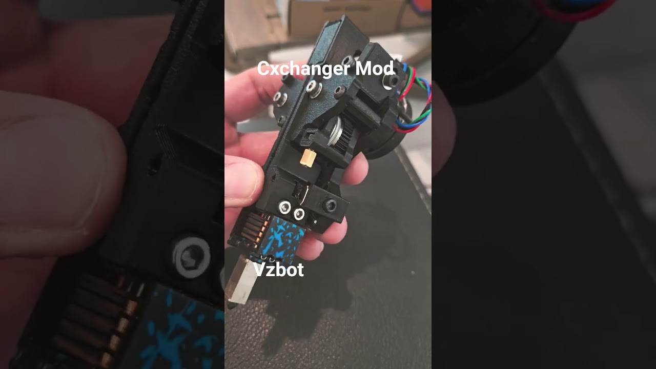
Toolchanger CXCHANGER Vzbot mod hotend changer
tawdry sleet
dusty plover
Great work! I’m still playing around a bit and I’ve nearly got a mount for a sta...
I ordered them cut to size 6mm pins to have them all consistent sizes, when they arrived they are 6.8mm 🙂 so I made the holes in CAD 1.9x7 with rounded corners 0.5mm, they fit very well, you just position 1 corner and push it down with something metallic, in my testing I didn't have any issues with them falling off. when I mount them in the printer I will also add a drop of glue to them just to be sure
On the pin idea, it will overconstrain the coupling and the result will be a worse alignment not a better one
if done properly a kinematic mount will be incredibly strong, On this test coupling I made, pushing sideways I can not pull it apart
my only concern is the cables+bowden tube may create a lever and coupled with extruder pushing may pull it apart, but if that's the case I will add 1 more magnet pair
tawdry sleet
dusty plover
I noticed this individual using spring loaded t nuts for additional grip: https:...
that is the exact thing I noticed when building my 1st iteration, at nozzle level I could feel it wobble
dusty plover
I’ll keep that in mind. I think I’m going to pursue this cxchanger style for a bit more and come back if I get anything of interest.
random geode
my issue with cxchanger is the fact the creator hasn't put it in english primarily - which is their right - it's not everyones first or even second language - just makes trying to follow the project a bit of a pain for me personally
dusty plover
someone's attempt to remedy that: https://github.com/WheelsTheCat/CxChanger
random geode
dusty plover
someone's attempt to remedy that: https://github.com/WheelsTheCat/CxChanger
neat - ty
versed path
tawdry sleet
good news, I managed to create a true kinematic coupling and it is extremely str...
this is the issue with fdm and precision i might have printed more than 10 back plate while testing maxwell coupling because 0.1mm difference can mess everything
now i know why cxc creator recommend cnc back plate lol
random geode
so is there a vendor fo the CxChanger CNC parts or is it a case of you've gotta get it cut by JLCMC or somewhere?
gritty ridge
random geode
so is there a vendor fo the CxChanger CNC parts or is it a case of you've gotta ...
There's a discord server for CxChanger in case you weren't aware.
random geode
gritty ridge
There's a discord server for CxChanger in case you weren't aware.
i was not
gritty ridge
random geode
i was not
One sec...
random geode
neither the OG repo or the translated one listed above mention a discord server for the project
 whole rockBOT
 sakitume has been warned
Reason: Posted an invite
random geode
you'll have to DM me bud
gritty ridge
Oh, looks like this discord server doesn't let me post links to other servers
whole rockBOT
sakitume has been warned
Reason: Posted an invite
gritty ridge
There's a link here I think: https://www.reddit.com/r/3Dprinting/comments/1vdpfi6/first_indx_clone_posted_on_bondtech_discord/
Was posted on bondtech discord. Different gears and mechanisms, but fully protected coil unlike INDX, seemingly better…

 Reddit
random geode
the link on the reddit thread is invalid
gritty ridge
haha...or maybe not
random geode
just send one via dm bud if you can - thanks - if not no worries
gritty ridge
sent
tawdry sleet
Update: 3rd Iteration
Alignment & Stability: The nozzle wobble is completely eliminated. Alignment is excellent and highly repeatable.
Assembly: Mounting is still tricky, but manageable using some custom-designed printed tools.
Current Challenge (Leverage Issue): The coupling handles parallel forces very well (e.g., extrusion pressure or nozzle probing). However, because the kinematic joint is centrally located, the nozzle below and the bowden/cables above act as large levers. Any forward or backward force at these extremities easily pries the coupling apart.
Currently brainstorming ways to improve this, my best guess is to keep the magnets in the middle but spread the balls/gooves as far as possible.
random geode
i mean theres a reason MadMax has so many magnets - i realise that madmax is an entire toolhead changer not just a filament path/hotend changer system but still
tawdry sleet
for the 4th iteration I'm switching from a cat design to a chihuahua design 🙂
 midnight latch
tawdry sleet
New day, new lessons learned:
- One pair of touching magnets exerts significan...
Well, yeah. When your magnets are outside the coupling, you can't ensure that the coupling always aligns.
gritty ridge
midnight latch
Well, yeah. When your magnets are outside the coupling, you can't ensure that t...
Why would that be?
midnight latch
gritty ridge
Why would that be?
Stable point can be without all pins and balls touching
gritty ridge
midnight latch
Stable point can be without all pins and balls touching
Hmmm, not able to parse and understand that
midnight latch
gritty ridge
Hmmm, not able to parse and understand that
If you apply a torque to the coupling, it may sit askew.
If the magnet forces are all within the triangle defined by the balls, it always aligns.
gritty ridge
midnight latch
If the magnet forces are all within the triangle defined by the balls, it always...
Ah, I see. Thanks for the clarification. I can agree with your point but can also conceive where it may be lacking. If the magnetic force were not within the triangle but closest to where the Maxwell sphere and grooves are located, I would imagine that would be more effective
The larger the distance between the triangle corners and the more central the magnetic attractive force, the higher the risk that a sphere/groove may not function as intended
Put another way, I feel losing that magnet on the bottom sphere (in the pic) rather than keeping it would be a net negative rather than a positive
tawdry sleet
Update: 4th Iteration
- "Chihuahua" Design: Proved to be the most reliable version so far.
- Alignment: Successfully preserves the highly repeatable alignment of the previous "Cat" design.
- Leverage Issue: Completely eliminates the leverage vulnerability at the top (cables/bowden) and significantly improves resistance at the nozzle level. While pushing or pulling the nozzle can still dislodge the toolhead, it now requires considerably more force.
Next Steps: I am satisfied with this design and will mount it on the printer. This effectively gives me a manual tool-changing setup with a single toolhead for now :). Moving on to real-life test prints.


 young lake
When you mount it can you measure the clearance between the gantry joint and the extruder motor ? I have a siboor kit, they are big and currently other toolchanger like cxchanger doesnt fit
tawdry sleet
young lake
When you mount it can you measure the clearance between the gantry joint and the...
my mercury one has the x gantry on top of the y rails so it runs quite tall so I designed it to lower the hotend as much as possible, if you look at the side photo the way the extruder motor is mounted there won't fit, because the plug would touch the gantry, the extruder motor stays a lot lower than cx changer
random geode
tawdry sleet
my mercury one has the x gantry on top of the y rails so it runs quite tall so I...
will this fit on a MercOne?
cause ngl my MercOne is my FAFO printer and it was gonna go on that before maybe my trident
tawdry sleet
random geode
will this fit on a MercOne?
I designed it for front mounted mercury one cuz that's what I have
random geode
tawdry sleet
I designed it for front mounted mercury one cuz that's what I have
sweet
tho i can't remember if my MercOne is MGN12 or MGN9 on X - but thats something easily swapped if needed
dusty plover
tawdry sleet
Update: 4th Iteration
- "Chihuahua" Design: Proved to be the most reliable vers...
Looks good! I was playing with your previous cad and was looking at docking. My concern at this moment is due to the cowl being around the hotend the pin to open the extruder gears needs to be pretty long. Other cxchanger-like mechanisms I’ve seen have part cooling fans underneath or at the back reducing the movement needed to clear the dock. There’s probably ways around this but the dock might need to be beefy to accommodate repeated use. Don’t know if you’re going to try a docking procedure yet.
 carmine agate
Hello, i am interested for my Mercury one to, mine the linear rail IS on top and mgn12 and the belts on the front. Is the same as yours?
 long hawk
mortal locust
Patiently waiting 🙂
What pink filiment did you use? I'm looking for a hot pink for blue extrusions. Ambrosia matte abs in hot pink ended up being a bubblegum pink. I may have to go with CookieCad to get a bright enough pink.
 amber plaza
long hawk
What pink filiment did you use? I'm looking for a hot pink for blue extrusions. ...
Not sure if you’re based in the US, but this seems like a good option: https://tonerplastics.com/product/village-plastics-abs-filament-reels/
ABS filament is a high strength, flexible thermoplastic suitable for 3D printing objects used in high temperature or industrial settings.
Oh god, 0.08mm tolerances, maybe not 💀
carmine lantern
Print fast enough and it won't matter as much 😄
 empty matrix
This looks amazing. Once you have a more or less stable bom and stls to print, I'd be happy to help testing.
tawdry sleet
carmine agate
Hello, i am interested for my Mercury one to, mine the linear rail IS on top and...
No, mine has the X linear rail on the front like voron trident, you just need to reprint the x joints the rest is the same, but don't do it yet, this design is very early alpha, wait until I have it working
carmine agate
I think i Will change It to the front because almost every toolchanger works with voron style,
Is just reprint the x joints, change again to normal 2020 and new linear rail
empty matrix
Do you have any STLs to look at per chance?
spice shard
long hawk
What pink filiment did you use? I'm looking for a hot pink for blue extrusions. ...
LDO pink
It's very pink
dusty plover
So I downloaded the CAD from @tawdry sleet that he posted a bit ago to try and work on it myself. I'll say it's really nice not starting from scratch and I'm grateful it was posted. I'm still playing around with mounting options and am not sure that I'm doing anything worth posting in the wake of the other solutions but I'm looking at the opening of the extruder. The CxChanger lends itself to it's own fanless hotends and other toolheads similar to VzBot and EVA designs due to the part cooling shroud not interfering with the docking maneuver. In the case of these A4T style changers there's a lot more depth from the front of the toolhead to the mounting. For context the CxChanger is about 20mm thick for the tool where these are more like 40mm. The pins to engage the tension lever need to be quite a bit longer as a result and we're looking at pins that are closer to 70mm or longer. I think the MedusaHC style (and A4T-C when released) make a bit more sense as the toolhead only needs to move in and out rather than do the little dance to engage the lever and concern itself with missed steps or the torque on that lever.
So I came up with this design: https://youtube.com/shorts/FlRJnokrzOQ?feature=share
It has a printed rack (I think that's the term) that pushes out the lever when engaged with the large drive gear. I've got a lot of work to do to determine if this is reliable and stands up to use but I'm surprised how well it works already. It takes very little force to engage and once pushed out by a retraction is held in place. A short extrusion movement pushes it back out to resume normal operation. I think I could make this use either a physical lever in the motion space or a servo to actuate it fairly easily.
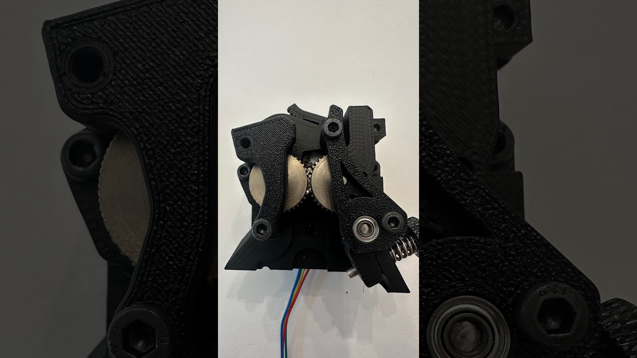
Extruder opening concept LGX gear extruder based on CxChanger and A4T changing designs.
This is closer to how I'm seeing Sovol build their hotend swapper which is where I got the idea. This isn't novel but I don't know if I've seen it discussed yet here so I wanted to throw it out to see if anyone has a good reason to shoot it down or if I might be on the right track.
elfin ice
dusty plover
This is closer to how I'm seeing Sovol build their hotend swapper which is where...
And now I thought. Why not use his too to lock in the hot end? (But sounds like a design nightmare 🙂 )
dusty plover
Honestly the footprint might be a little off from the Maxwell coupling ycsy developed but probably not too much. I could make it compatible when he decides to provide updated CAD next.
tawdry sleet
dusty plover
So I downloaded the CAD from <@212278001381933058> that he posted a bit ago to ...
it looks really nice, that part made of plastic might be a bit fragile given that the teeth won't lock in perfectly every time, it's a great idea.
my current idea for docking opening the lever was to have the whole movement on the dock where you can use stronger heavier motors and mechanisms, but I haven't started working on it until I checked the coupling, here is the latest version with the update coupling it is a lot easier to assemble correctly than the original cxchanger
dusty plover
Thanks! I’ll check it out. The part being plastic does concern me a bit but it opens the mechanism really easily. I’m trying to figure out a way to make a test rig to see if I can get it reliable over time. I’m also adding in a few extras to make sure it stays off the teeth when not engaged.
tawdry sleet
dusty plover
Thanks! I’ll check it out. The part being plastic does concern me a bit but it o...
you can add a spring beneath it a small limiter so that it doesn't go very high up but it still needs a way to engage
potent imp
dusty plover
So I downloaded the CAD from <@212278001381933058> that he posted a bit ago to ...
Very nice. not sure if you need a sensor in there, but I just finished slapping one on an LGX. Might save you lots of time. Works awesome.
potent imp
versed path
dusty plover
So I downloaded the CAD from <@212278001381933058> that he posted a bit ago to ...
This is sick, if you can manage to add one way bearing to this to make it all mechanical without a lever arm or a servo like yudx it would be amazing 🔥
gritty ridge
dusty plover
So I downloaded the CAD from <@212278001381933058> that he posted a bit ago to ...
This looks very good. I applaud your creativity as well as actually building a test print to properly evaluate.
This is very similar to several other designs in using the extruder stepper itself to actuate the extruder swingarm. But it is also very different in the mechanism you have come up with.
Your idea of using a servo or another mechanical lever sounds good as well. Srin designed his to use a mechanical system and I really liked how that worked for me. But it did some other clever things as well. Sergei's use of a servo also appeals to me but I don't have any direct experience with that method.
Please let us know if you are able to share. I would be interested in helping you test just the mechanism (rather than the entire extruder) as I already have a test bed/platform and custom Klipper extension that performs the extruder stepper manipulations to open/close. It's possible they could be easily adapted to test your mechanism, but they were written to take advantage of the design that once opened, it would stay open until the stepper was instructed to extrude.
Whether you feel comfortable to share or not, I encourage you to continue with this idea. I sincerely believe it is worth more to try something with actual test prints and physical evaluation versus trying to make design decisions primarily in the abstract via CAD or Discord chat. So seeing you do exactly this in your video is awesome to see.
dusty plover
Thanks for the encouragement. I’ll probably share in the next few days after I have some time to clean up the cad, finalize engagement and disengagement and verify compatibility with ycsy’s coupling. It should be compatible but my initial check showed the lever bumping the hotend mount when at its open position so it needs a small tweak.
cyan barn
@gritty ridge are you on the final stages of the BBox? I saw the Spiderman bust on YouTube.
gritty ridge
cyan barn
<@520048236535480320> are you on the final stages of the BBox? I saw the Spiderm...
Getting closer to a having a beta test. I want to make some adjustments to a couple of parts but nothing major. The core of the Klipper extension is solid but I want to refine the accompanying UI a little more (integration with Mainsail works well, but I haven’t had a chance to test it in Fluidd). I have two alpha testers helping and their builds are coming along. Once they are both successfully printing I think that would be the necessary milestone to allow opening it up to beta testers.
cosmic plover
Something I just thought of, but has anyone designed a modular auto loading system for open source 3D printers like a Voron? Not like a full on MMU type system, but something that would make it easier load filament into X number of tool-heads like what the Snapmaker U1 has.
dusty plover
cosmic plover
Something I just thought of, but has anyone designed a modular auto loading syst...
Look at the Bowden speed loader. It’s a manual switch but at its base it’s what you’re looking for.
empty matrix
It'll be interesting to compare sakitune's and Ycsy's versions. Are there plans to merge them into one at some point or have the designs diverges too much?
 potent yoke
cosmic plover
Something I just thought of, but has anyone designed a modular auto loading syst...
I have seen EMU used like that with a U1
tawdry sleet
dusty plover
Look at the Bowden speed loader. It’s a manual switch but at its base it’s what ...
something like ERFC's loader based on a stepper motor that would work in sync with the extruder using a SPF sensor would be nice, it would be a bit overkill considering it's x4 x5 x6 or however many hotends you have
 vernal valve
cosmic plover
Something I just thought of, but has anyone designed a modular auto loading syst...
I have that running on my sc
 amber plaza
vernal valve
That looks sick as hell, what is that?
Same question about the panel system
vernal valve
amber plaza
That looks sick as hell, what is that?
5 Filamentalist, 5 ProtoXtruder 2.0 and 5 PFS + some Endstops 😄
vernal valve
amber plaza
Same question about the panel system
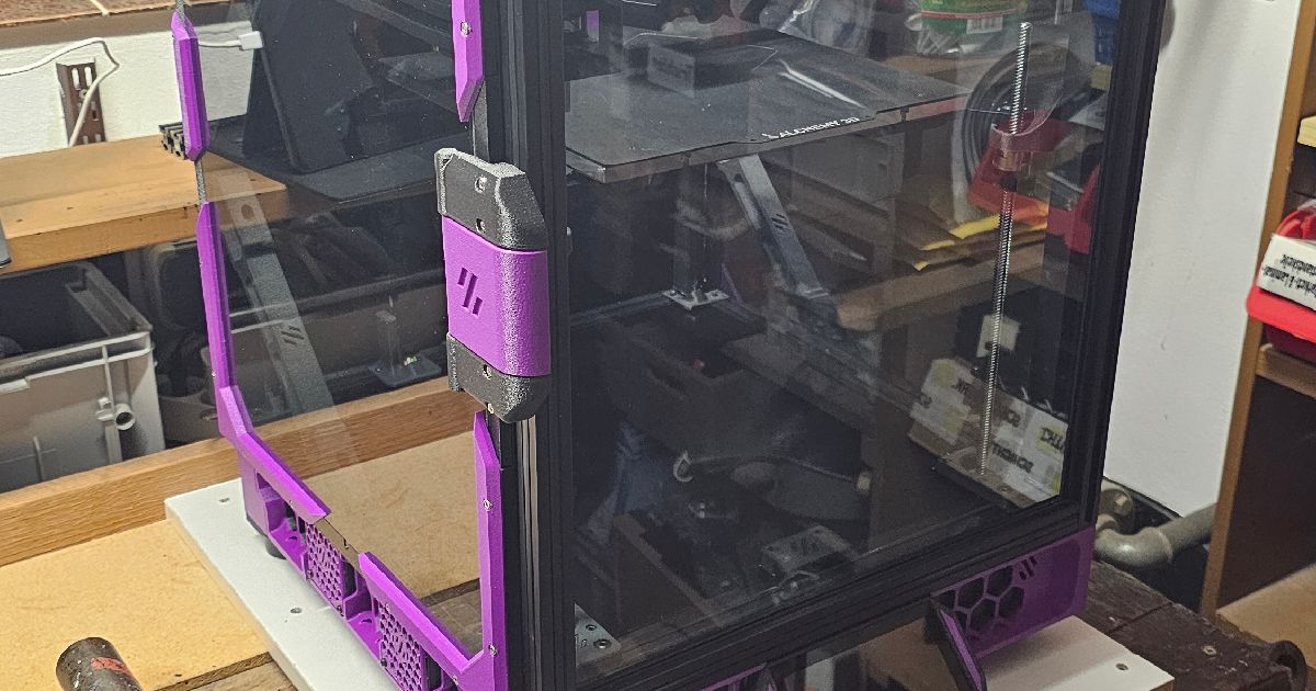
Printables.com
Voron Panel mounts with clearance at backside and to the gantry. | Download free 3D printable STL models
random geode
some sort of spacer frame?
amber plaza
vernal valve
https://www.printables.com/model/1116554-voron-24-trident-panel-mounts-with-clea...
Exceptional work, thank you
 humble bridge
vernal valve
5 Filamentalist, 5 ProtoXtruder 2.0 and 5 PFS + some Endstops 😄
What do you mean with PFS?
vernal valve
humble bridge
What do you mean with PFS?
Proportional Feedback Sensor
Like an belay in nice
humble bridge
vernal valve
Proportional Feedback Sensor
Thanks and all the mounting stuff is made by yourself?
vernal valve
humble bridge
Thanks and all the mounting stuff is made by yourself?
Yes
dusty plover
So here's some cad with the rack and pinion mechanism to open the extruder. A few notes:
- I separated the extruder lever to assemble with 2x10 self tapping screws - let's you print it without supports.
- The lever is held up by the shear force from a magnet attracting a screw - I'm still verifying reliability and might need to beef it up.
- I added a servo to actuate the mechanism but it is separate from the system to actuate from something else. The servo was the low hanging fruit that was still a good solution (and I like the idea of actuation independent from movement).
- There's a micro switch to detect opening that triggers when the opening is near it's max.
- I included a lever arm that uses a heatset and one that uses a square nut.
- It should be completely compatible with the coupling mechanism designed by Ycsy
- I've only tested this mechanically by hand. I've got a few more parts to assemble before I plop it on a machine.
feel free to let me know any feedback.

 dusty plover
to make a quick acknowledgement the servo mount was basically ripped from the Medusa HC project. I think the fit might need some adjustments before it's reliable.
tawdry sleet
I am testing the coupling with real life print, tomorrow I will print your mix @dusty plover to test the lever mechanism
I tested fully "clogged" with the hotend cold and the motor skips steps or chops the filament and the coupling doesn't move
I tested cartographer tap and it works flawlessly
dusty plover
I adjusted the depressor arm and fixed two holes in the rear that may have gotten misaligned while I was combining changes. Thanks for taking a look!
I've only run off portions of the main body but am finally running off the whole thing. @tawdry sleet how exactly were the ball bearing inserted into your hotend mount? If you cut down some threaded rods to hold them or however you aligned them it might help to know. I've got 4mm rounded pins that are 5mm long that seem nearly compatible (I know you mentioned these previously) and am playing with the hotend mounts to get a solution that doesn't have me mess up the part upon insertion.
tawdry sleet
dusty plover
I've only run off portions of the main body but am finally running off the whole...
I've built 2 versions to test which is better 1 with M4 5mm spherical pins from aliexpress and the other with piercing balls with a 2mm screw, the piercings are a lot better, smoother and easier to align
 severe dawn
I wonder how much force filaments like PET-CF will push on the hotend along the Y-axis, and whether it might even fall off during printing.
tawdry sleet
I used this precisely push the balls

that is an short M4 screw with a nut glued with 1.8mm space left inside the nut
this allowed me to push the piercing ball precisely and repeatable
afterwards I added a drop of AC glue next to it and the binding was permanent, you had to break the plastic to remove it
tawdry sleet
severe dawn
I wonder how much force filaments like PET-CF will push on the hotend along the ...
I tried with ABS with a cold hotend to simulate a complete clog, the coupling didn't move
@dusty plover in theory a ball bearing should work as well, use a 4mm ball, create a cilinder d3.8mm x 2.2mm and cold push it then add a drop of glue to fill the gaps around the ball more than to glue it to the plastic, it should work
tawdry sleet
@dusty plover in your design, the depressor is pushing down on the toothed plastic part to lock it in place on the main wheel when you want to open the extruder, but what is pushing it back up? are you relying on the elasticity of the plastic to pop back up?
dusty plover
The extruder pulls the lever down a bit to open and it pushes it back up to close. This seems to result in it lifting it above but I’m still messing around to make sure it’s reliable. There’s a spot in the lever to screw in a 6mm m3 bolt and a 3x6mm disc magnet on the back of the lever arm. This creates some shear force to lift the arm as well, not sure if it’s enough at the moment though
However I am now realizing the screw interferes with the servo mount. I’ll update CAD in a moment
Nothing helps you find problems like sending the project to someone else:
severe dawn
tawdry sleet
I tried with ABS with a cold hotend to simulate a complete clog, the coupling di...
in z direction 🙂 what about y? when the bowden tube/filament pushes the hotend to the front in some cases
dusty plover
obviously testing is needed and being spun up but I do have a madmax setup with 3 tool heads. This also uses a maxwell couping with 6x n52 3x6mm magnet pairs. Its been solid. This system is holding less weight with 4x pairs of the same magnets. My initial thoughts are it should be good so long as the filament path isn't too constrained vertically.
gritty ridge
dusty plover
obviously testing is needed and being spun up but I do have a madmax setup with ...
Thanks for sharing the CAD. I hope to find time to examine and test a mock-up of the mechanism you made for opening the extruder tensioner swing arm. I really like the idea of using a rack like you’ve done. What material are you currently using for it?
dusty plover
Test prints were pla, for testing now I’ve got it all run off in Asa-gf. I think plastic could hold up quite well for the limited use it’ll be in. If not I’m wondering how expensive it would be to EDM machine it.
cosmic plover
@tawdry sleet I saw in a different place/thread that RC car ball joint screws may be a good candidate for kinematic coupling.
https://www.hobbytown.com/omphobby-m4-380-rotor-ball-joint-screws-6-2x3mm-omp-oshm4064/p1518687
tawdry sleet
cosmic plover
<@212278001381933058> I saw in a different place/thread that RC car ball joint s...
those would work in theory, except for the very top ball which has very little space between it and the bowden tube, a redesign would be needed to use these
tawdry sleet
dusty plover
Test prints were pla, for testing now I’ve got it all run off in Asa-gf. I think...
I will print those out of asa kevlar, I have a spool around and I've found that material to be very strong when printing small parts that need to withstand force
carmine lantern
I found bearings with a threaded hole in them on ali a while ago for a different project I never finished - I wonder where I put them. 😅
tawdry sleet
@dusty plover I did some small changes with things I learned from my real life test:
- added a chamfer on the back where the fans meet the xol carriage because it was interfering with the belts
- moved 1 fan 0.5mm forward
- a few changes on your design:
- replaced the screw on the opening tool with another magnet facing the other, in theory the screw-magnet attraction should be enough, but I want to be sure that won't move and accidentally open the extruder mid print and 2 magnets face to face touching each other should make sure that doesn't happen
- changed all the heated insert holes to d4.7x4.5 because I have a lot of inserts M3 x 5 x 4
I'll calibrate my printer for ASA Kevlar and start printing everything
tawdry sleet
carmine lantern
I found bearings with a threaded hole in them on ali a while ago for a different...
these are really common and cheap and you can usually find them locally
https://www.amazon.de/-/en/Pack-Balls-1-2-1-6-Thread/dp/B0B6FM5C6K?th=1&psc=1

5 x screw on ball made of 316L surgical steel in silver.
Thread:
1.6 mm.
Ball diameter:
4 mm.
The balls can be screwed onto any jewellery with an external thread of 1.6.
dusty plover
I also ended up replacing the screw with another magnet 🧲 it seems to work more reliably. In addition I’m using another 6x2.5mm bearing on the screw to see if that helps it pull up easier.
tawdry sleet
I printed it out of asa kevlar, it moves easily with a d6x2.5 bearing and it bounces back due to the magnets instantly, but it looks soooo weak I think it needs to be a bit thicker
 night perch
dusty plover
So here's some cad with the rack and pinion mechanism to open the extruder. A fe...
Can you explain about this? Is this A4T-C or your take on the concept? Different from A4T-C?
tawdry sleet
the ultimate test for the coupling
this was printed with the chihuahua coupling at 500mm/s speed with 12.000 mm/s2 acceleration ... it passed the test imo

 tawdry sleet
night perch
Can you explain about this? Is this A4T-C or your take on the concept? Different...
it's a different design, we didn't have access to the original design
random geode
isnt Slimohan off dealing with IRL issues at the moment?
dusty plover
tawdry sleet
I printed it out of asa kevlar, it moves easily with a d6x2.5 bearing and it bou...
Since all force is directed down the shaft it’s been holding well. I’m going to try and run a stress test once I’ve got it hooked on a machine to see what it can handle but it hasn’t felt weak in my testing so far. As always though this thing is an experiment.
 dense stirrup
random geode
isnt Slimohan off dealing with IRL issues at the moment?
Think he is moving or something
night perch
tawdry sleet
it's a different design, we didn't have access to the original design
Ok, cool. It’s a bit confusing. Maybe a separate mod channel?
dusty plover
Honestly a separate channel might be a good idea at this point given differences in design decisions.
gritty ridge
dusty plover
Since all force is directed down the shaft it’s been holding well. I’m going to ...
That's why I am particularly interested in your design (rack is pushed along its length versus a cam lobe on a shaft). Several of us experimented with various cam designs on Quindec and I hope to find time to experiment with your rack idea.
carmine lantern
I think a collaboration in the community to make a great open source toolchanger is a good idea rather than 10 competing/conflicting designs personally
empty matrix
I agree, but that is an unreasonable expectation in the tinkering phase. I'd rather see many bright minds trying out different designs. Ideally all of that culminates in a democratically emerging common solution.
I for one really like Ycsy's approach. Loaks simlle enough without any belts and whistles. But others like servo approaches (which I don't because its more parts that need to be controlled separately).
@tawdry sleet, do you have any vids of it in action?
mortal locust
long hawk
What pink filiment did you use? I'm looking for a hot pink for blue extrusions. ...

West3D 3D Printing Supplies
Please note: Dolos Filament is more hygroscopic than normal filament, we recommend drying/keeping it dry for best results. Ambrosia Filament's line of ASA is part of our Low Calorie line of filament, no additives just butter smooth printing. Feed your Printer the Filament of the Gods. Dolos - the Greek spirit of tricke
urban solar
The dolos filament is known to have issues when used anywhere structural
carmine lantern
I really like the one way bearing idea for opening the tension arm - no additional servo or relying on the axis steppers via a dock post to open it.
Down side is retractions are limited to less than the reverse engagement distance of the one way bearing.
urban solar
Those one way bearings are known to fail too
dusty plover
Not really an update on testing the rack and pinion opening mechanism but I wanted to share some thoughts on adding pins to a plastic piece. The maxwell coupling needs to be relatively precise in the sphere position and using rounded pins has been troublesome but I looked at what was going wrong and ended up coming up with something that worked well. The pins need to be tight in the holes and issues arose when inserting a pin at an angle or if the hole was too undersized. It resulted in some plastic getting sheared off and pushed down the hole raising the pins sitting position or even keep it an angle rather than sitting correctly. This is worse if the pin is short or if there’s not a nice chamfer on the inserted end. I’ve been using 5mm M4 rounded pins and getting these issues.
I came up with actually putting a relief around the bottom of the hole for sheared material to go into as well as reaming the hole with a longer pin and some bushings to get a nice straight hole. It’s made inserting the short rounded pins easy to do and they sit really nicely. They’re still nice and snug and require a flush cutter to pull out. I’m including an image to try and illustrate but if anyone’s frustrated inserting small pins into a print it may help to try this.

I can’t imagine this is novel, but I haven’t seen it used yet in the 3D printing projects I’ve done.
cosmic plover
urban solar
The dolos filament is known to have issues when used anywhere structural
That's a bit disconcerting. Titanium Anno is my primary color on my 2.4 350 build. But at this point the only structural part that is printed are the bodies of the Super Beefy Z Idlers. (SBZI)
gritty ridge
carmine lantern
I think a collaboration in the community to make a great open source toolchanger...
I would argue we already have several good open source designs available to work with today rather than making a single new one.
I am referring to existing designs that are already fully usable and ripe for tuning and enhancement and customizing to meet your needs or to just use as is and enjoy printing with.
Having several options is good for the community as there isn't one particular design that is ideal for all use cases
I love seeing all of the variations people are experimenting with. I have built several of my own designs and hope to try out ones others have designed or currently designing.
These hotend changers are so much more cost effective than full blown tool changers that if you are the type that likes to experiment and build, there is no shortage of ideas to play with today and have a lot of enjoyment
 prisma ether
dusty plover
Not really an update on testing the rack and pinion opening mechanism but I want...
Hello. First time posting, but I've been lurking here for a while 👀
One suggestion to add up to your idea: add splined holes. This way you can get away with building even more interference. The extra material will deform and have somewhere to go. This design tends to be more forgiving than a round hole precisely the right size, and id argue its capable of providing a better fit.
 versed path
dusty plover
Not really an update on testing the rack and pinion opening mechanism but I want...
yeah i had the same issue then made the hole longer and added chamfer to make it self center but still getting the dimensions of the hole precise so it goes in straight is a struggle
 dusty plover
The reaming bit really helps it be straight. And in addition to splines making the hole hexagonal has a similar effect.
potent imp
I am wondering if it would just be simpler to have an extruder on every tool, and just mate the motor gear.
carmine lantern
There's a chance you'll get a collision when trying to mesh the gears over and over
potent imp
I was thinking a coupling of some sort with a taper and also rotating the extruder back and forth one tooth pitch of whatever engages.
dusty plover
The creator 5 does this. There’s also a toolchanger project called blackbox ce that does this. If space isn’t an issue a full tool head changer is probably actually the simplest, just takes the most parts.
tawdry sleet
@dusty plover I did a real life test with the lever mechanism, a few issues that need to be addressed, I will fix them later today and reprint:
- it needs significantly more distance between the lever and the main body, the spring tensioner doesn't do much because it doesn't have space to pull the lever closer
- the magnets snapback mechanism works in your hand, when you move it, it snaps right back, but because in real life test the rotation is only 5-7 degrees it's not enough to force the magnets to realign
- the rack doesn't seem long enough but that may be due to issue 1, if it were pushed forwards 1mm or so it would be enough
dusty plover
Thanks for the info. I’ll take a look as well. Did you test the prying method at all from the design you were working from? I’m interested in how they would compare.
tawdry sleet
I did, it had a lot of room to move, it would open up to 4mm if needed, with this design i could only open it ~1-1.5 mm, let me share a video 1 min
this is with 1.5mm retraction, but in reality it only moves it ~1mm afterwards it runs out of teeth and it's not enough for the filament to exit
dusty plover
Is that the motor skipping or where does the stuttering come from? My hand held test had a much larger gap.
Hmmm… I’ll spend some time trying to figure out that discrepancy. I’ve almost got mine built to hopefully do some motion tests tomorrow.
tawdry sleet
yes the extruder motor is skipping
dusty plover
Hmm…. Thanks for the video. That helps to see what’s going on. I’ll see if I can replicate that.
tawdry sleet
the real reason why it's skipping is due to the servo
the servo is extremely strong pushing on that gear
btw ... from what I've seen imo the servo can easily open the lever on it's own
let me try to adjust the angle of the servo so that it doesn't push that hard on the gear and try again
dusty plover
My impression was that the servo would engage the racking mechanism then pull away as the racking lever is pulled down by the large gear. I can’t really make out what’s happening in the video to see.
I think there’s a project for the e3ng that’s a toolchanger that just uses a servo to push the arm open. May be worth a look.
tawdry sleet
it's not due to the servo, even pushing by hand on the rack it locks in place and skips, it's due to the force required
I tried spinning the gear by hand and at the very end of the rack it completely locks in
dusty plover
Yeah, I’ll try to reproduce to get a feel for it myself. It’s 90% there. Thanks again for testing. I think there’s a path forward still just gotta refine some things.
tawdry sleet
I'll try a new design later today to see if the servo is enough
I don't really like that racking mechanism, it feels the weakest point in the design, you can't build it at cnc and made of plastic it only takes 1 missed engagement to break all the teeth
dusty plover
That’s a fair criticism but I’d like to verify it myself. I think some of the manufactured ones use a similar concept and while it’s a Cnc part I feel like I might be able to replicate it well enough.
gritty ridge
tawdry sleet
it's not due to the servo, even pushing by hand on the rack it locks in place an...
I temporarily boost the extruder stepper motor current when using it to open the extruder. It’s a necessary step for the designs I tried and built. I also don’t tension these extruders any more than absolutely necessary otherwise the mechanism suffers fatigue and breaks somewhere. I spent a couple of months on this until I was happy with my end result
I have many broken parts and corresponding revisions as well as different springs but in the end achieved what I felt was a fairly solid design that could handle thousands upon thousands of changes
gritty ridge
dusty plover
My impression was that the servo would engage the racking mechanism then pull aw...
That is the toolchanger by EMNA.
dusty plover
I plugged mine in (just the extruder and necessary parts to boot) and initial testing wasn't nearly so negative. The extruder opened enough that filament just fell out (no hotend in the path) and it had decent grip on it beside that. There's definitely some refining and I need to play around with the little dance it does to engage properly (no servo, just pressing it for now) but I'm still optimistic for the moment. I'd like to get it opening a bit more though so I'm going to work on the gear geometry.
empty matrix
Regarding the pins, isn't the relative height of the 3 mating surfaces significantly more important than whether the pins are slanted a bit? If the top is a sphere, I'd imagine that being rather irrelevant. I'd imagine a shape like this for the holes instead.
|     |
|  _  |
|_/ \_|
The servo is strong enough with a long enough lever, I will share the updated design on Monday I need to move the servo a little because it interferes with the ebb36 mount ... but it works, the only odd thing is that the filament gears sometimes get misaligned (tooth on tooth) and I added a small extruder movement to put them in place, that may be completely unnecessary in real life usage because as soon as you move the gear they snap right back in place
One more thing ebb36 doesn't seem to have enough power for carto, servo and neopixels, so you either have to route 5v from the mainboard or drop the leds
dusty plover
I’ve seen the gears thing too and any jiggle just fixes it. The Medusa HC project also had the power issue and needed 5v from a dedicated source for some servo. Are you using the gen1 ebb36? In wondering if the newer one has a beefier 5v rail.
tawdry sleet
I have gen 1 with maxx chip, the leds work up to ~50% then you get carto errors so it's right on the edge even without leds
urban solar
Gen 1 is rated for 1amp Gen 2 is 1.5
dusty plover
I've got a gen 2 but it's not on the machine i'd like to prototype this on. Might swap it in.
Also, I picked up a bunch of those clone bambu lab x1 hotends for really cheap with the intent of using them on a toolchanger. I made a mount that's compatible with all the CAD we've been throwing around.

It's also got the geometry set up for the rounded pins for the method I described [here](#1522282695516885204 message)
gritty ridge
dusty plover
I've got a gen 2 but it's not on the machine i'd like to prototype this on. Migh...
Thanks for sharing that link. That is definitely a good price for a complete hotend with heater and thermistor. I just ordered 10 of them for a couple of new toolchanger prototypes I am building
dusty plover
gritty ridge
Thanks for sharing that link. That is definitely a good price for a complete hot...
They’re from the Medusa HC BOM. Just watch out since some clones have wiring on the other side of the hotend than stock ones. I’m not totally sure as I’ve only had the clones.
gritty ridge
dusty plover
They’re from the Medusa HC BOM. Just watch out since some clones have wiring on ...
Thanks, I'm optimistic they'll be fine. I've had good luck and only buy when they are on sale. I have a good stockpile of the TZ2 and TZ3 hotends
 molten wasp
potent yoke
I have seen EMU used like that with a U1
I was thinking of the single lane EMU attached to each toolhead feed.
molten wasp
tawdry sleet
The servo is strong enough with a long enough lever, I will share the updated de...
Really like the motion, the extruder gears are really opening well.
I noticed the bearing on the servo arm, are you concerned about the extruder arm wearing quickly? Are you thinking of using a really hard wearing material, or perhaps using CNC parts for both?
molten wasp
tawdry sleet
I have gen 1 with maxx chip, the leds work up to ~50% then you get carto errors ...
Might not be popular, but what about the SHT36 V3?
tawdry sleet
molten wasp
Really like the motion, the extruder gears are really opening well.
I noticed t...
honestly I am trying to reduce the friction as much as possible
tawdry sleet
molten wasp
Might not be popular, but what about the SHT36 V3?
I changed the macros by turning off every 5V consumer from the ebb36 when opening the extruder and turning them back when closing and it works even with ebb36 v1
molten wasp
tawdry sleet
I changed the macros by turning off every 5V consumer from the ebb36 when openin...
Clever work around. Do you think a different board would eliminate the need for the macro?
tawdry sleet
molten wasp
Clever work around. Do you think a different board would eliminate the need for ...
Yes, any board with more than 1A power budget on the 5V rail would be fine, or with fewer consumers, it may be that once I properly connect the hotend and hotend fan directly to the main board this won't be needed for me either, I have it wired to the toolhead cuz I didn't have time to do the wiring
dusty plover
So the servo only latch opening that @tawdry sleet made is really compelling. I mocked it into the system I’ve been prototyping and so far it’s working well. I might build out the remainder and try to print. I did change the servo arm to a spiral and put a bearing on the lever in case that’s an idea that might help. I’m going to tweak a few more things and then see if I can get a macro going to stress test.
Hopefully we’ll see some toolchanges soon.
empty matrix
The thing that irks me most about the servo idea, is that it adds quite a bit of mass high up on the toolhead. I'd imagine that it has a detrimental effect on print quality at high accelerations. It'd be grand if someone could test this. If you tell me how much weight that is, I'd mock up a test myself.
tawdry sleet
The servo has 17 grams, the whole mechanism adds ~30 grams, let's have a working toolchange and then we can look into ways to improve it iteratively
urban solar
30 grams is not going to make a drastic difference
empty matrix
Its several centimeters above the rail. Its the twist that I am worried about, not the weight itself.
tawdry sleet
Single toolhead toolchanger 🤣
empty matrix
Btw, are you aware that a new version of A4T is in the works?
severe dawn

GitHub
Version 2 of [A}nother [4]01x [T]oolhead. Contribute to DW-Tas/A4Tv2 development by creating an account on GitHub.
random geode
severe dawn
https://github.com/DW-Tas/A4Tv2
see the great thing about A4Tv1 was its simplicity, you had 4 main things to print... hotend mount, fan shroud, outer shell, extruder adapter plate - boom done - that's A4T - sure you could do LEDs and toolhead board mounts n shiz - but the main body was 4 prints total - v2 seems a lot more "complicated" especially compared to v1 - with the bolt on 4010s and such - not that it'll be difficult to build or anything - but its not 4 parts any more
empty matrix
I mean, its a few more but not really a lot.
potent yoke
random geode
see the great thing about A4Tv1 was its simplicity, you had 4 main things to pr...
the other great thing about A4Tv1 is that it's all still there. If you're not planning on using the 4015 fans you can still use the old one.
random geode
oh i also didnt realise the fan swap - good call out 🙂
potent yoke
yeah, that's why the ducts were split off. It was the only way I could get the bigger fans in the same footprint
random geode
fair nuff
potent yoke
I think v1 lends itself better to this project though. mounting the fans otherwise could be a challenge in a hotend changer
empty matrix
I'd for sure create a remix trying to go for 4015. You can never have to much cooling :D
spice shard
empty matrix
I'd for sure create a remix trying to go for 4015. You can never have to much co...
Well technically there's also A5T but @potent yoke may personally send Tasmanian devils to haunt you 
potent yoke

 lone plinth
I like the new design, you dont have to rip out the fans everytime you change hotend
dusty plover
I think the current mechanisms in testing are pretty flexible and don’t lock modification out. It should be relatively easy to split off the fan assemblies and slap something else on, even adapting to other tool heads. Getting this on something with a top mounted mgn12 and rear fan would be easy. I’ve always thought the Eva style tool heads lend themselves better to hot end swappers with their rear fan mounts.
The only thing I can see being difficult in its current configuration is cpap since the tube needs to be routed behind the extrusion path when it’s usually in front for Voron style tool heads. It would have to route similar to indx.
mortal locust
urban solar
The dolos filament is known to have issues when used anywhere structural
I have found that anything that adds something to ASA usually makes it less sturdy. Good old solid colors with nothing special is the best way to go. But where's the fun in that 😉
viscid vale
tawdry sleet
The servo is strong enough with a long enough lever, I will share the updated de...
What servo are you using?
tawdry sleet
MG90S with metal gears
viscid vale
👍 Perfect, I have some of those. I'm thinking about going this route. I've had a look at your CAD and it looks really good. I think I have everything I'd need to build a print head. I am using Qidi Plus 4 style hotends but it looks very possible to modify your design to make those work.
Have you uploaded the CAD with the servo directly actuating the tension arm anywhere?
dusty plover
viscid vale
👍 Perfect, I have some of those. I'm thinking about going this route. I've had...
I put together one for a x1 style mount: #1522282695516885204 message. It should be a decent starting point if you’re giving it a go
 stoic vapor
What's the feasibility of this going on a misschanger v2?
Wait, that might be a stupid question. Is this a full toolchanger in and of itself?
Yeah, I'm just being dumb
viscid vale
dusty plover
I put together one for a x1 style mount: https://discord.com/channels/4601176029...
Yes, I saw that and downloaded your file. It will work with minimal modifications. Thank you!
 thick shale
potent yoke
the other great thing about A4Tv1 is that it's all still there. If you're not pl...
Off topic, but out of curiosity, what compelled you to revise the design of the A4T?
potent yoke
thick shale
Off topic, but out of curiosity, what compelled you to revise the design of the ...
I like making things
🤷♂️
thick shale
Oh, cool
I was just wondering if there was a game changing flaw or missed opportunity you couldn't bear living with
potent yoke
thick shale
Oh, cool
I was just wondering if there was a game changing flaw or missed opport...
those 4015 fans from peopoly are seriously good in comparison to 4010 fans
carmine lantern
Math says 50% better. 😉
could be more than that though if the walls are 1mm thick then it's actually 8 to 13mm which is 1.625x better
potent yoke
carmine lantern
Math says 50% better. 😉
The issue is that most 4015's actually aren't better than 12k 4010s
the math doesn't math 😂
carmine lantern
Yeah, figures
 noble minnow
so my 2x HoneyBadger Performance Series 4010 Blower Fan are better than the 4015 from peopoly?
potent yoke
noble minnow
so my 2x HoneyBadger Performance Series 4010 Blower Fan are better than the 4015...
not even close. The peopoly 4015 is closer to a 5015 than to the 12k gdstimes
and I think the honeybadgers are basically the same as the gdstime 4010s
carmine lantern
that name though - Peopoly Magneto X Lancer Extruder Side Turbo Fan
Are people just getting AI to name their products now? 😮
potent yoke
carmine lantern
that name though - Peopoly Magneto X Lancer Extruder Side Turbo Fan
I think that name is from mid 2024
gritty ridge
dusty plover
So the servo only latch opening that <@212278001381933058> made is really compel...
This looks great @dusty plover I would love to try this out. I was hoping to find time to evaluate EMNA toolchanger (which uses this approach) but never got around to it. But since you have a mockup/prototype underway I think it would be great to give your version a spin once you are able to share the .step file. Please let me know when/if that happens. Thanks
gritty ridge
tawdry sleet
Single toolhead toolchanger 🤣
Amazing progress @tawdry sleet , this is so great to see
tawdry sleet
Thank you ... I have everything for the next step, but I need time, I decided to go with 5 toolheads I could fit 7 maximum but 5 feels enough for now I can always scale it

wiring will be ... fun :), I've added a creality 2.2 I had abandoned in a drawer next to my btt kraken to have more extruder/thermal probe headers
but in total from the motherboards to the toolhead mounts I will have 40 different wires (10 thick, 30 thin), I need to find a way to cable manage them
This is the latest CAD, I am pretty confident in the coupling opening/closing the extruder, the dock is designed for the very custom build I have so if you want to use it make sure to adjust it for your build
I went with the piercing balls in the end, they are significantly better machined than any rounded pin and are easier to insert
gritty ridge
tawdry sleet
wiring will be ... fun :), I've added a creality 2.2 I had abandoned in a drawer...
That sounds good. 5 is a great number. 8 is actually tricky to do with all of the PTFE tubes to deal with.
For wiring, I have it easy as I only need 4 wires per hotend tool so I use USB-C cables and connectors which makes it also easy to swap out or replace entire tools in seconds.
But for your build (with hotend fan on each hotend tool) you need 5 wires for the heater, thermistor and fan. So unless you have something else with your build you could simplify it to 25 wires instead of 40.
The MedusaHC folks have some nice builds where they use cable sleeves.
tawdry sleet
each hotend has: heater, thermal proble, fan, LED, minimum I could go with is 10 for heaters 10 for thermal probes and 6 for all fan/leds (common ground for all fans and LEDs in parallel with the fan, they are simple orange 5V blinking LEDs)
I don't want to combine the ground for thermal probes and heaters, for probes to avoid interference, for heaters due to the high current
In the end I want to build a orca slicer plugin to lower the temperature of parked toolheads to 150 C and add preheating macros in the gcode to increase the heat a few steps ahead of toolchange so that when the tool changes it will be on the right temperature to start printing
hopefully with everything tunned correctly, toolchanges will be consistently under 5s
gritty ridge
tawdry sleet
each hotend has: heater, thermal proble, fan, LED, minimum I could go with is 10...
The heater and hotend fan are driven with an active ground for each. So they can cleanly share the 24v line. The thermistor would use its own dedicated pair of wires. The LED could go in parallel with your fan. So you only need 5 wires for each tool.
gritty ridge
tawdry sleet
In the end I want to build a orca slicer plugin to lower the temperature of park...
OrcaSlicer already has what you need so no need for a custom plugin
tawdry sleet
cool I didn't know that
gritty ridge
tawdry sleet
hopefully with everything tunned correctly, toolchanges will be consistently und...
Yes, I think you will achieve that speed for your tool changes
tawdry sleet
right now with a single toolhead change, parking and loading the hotend is consistently under 1s
with travel 400mm/s aproach 180mm/s maneuvers 20mm/s
gritty ridge
tawdry sleet
cool I didn't know that
It's under "Ooze prevention". You specify a temperature difference between print temp and standby. And preheat time in seconds. But you can provide an explicit standby temperature per filament which overrides the other setting and that is what I prefer to use
tawdry sleet
I can tune those to get a 100% consistent load/unload at maximum speed
found it, the main advantage of rapido 2 hf hotends is that time can be very low
it has 115W heater it will go from 150->220 in 2-3s
gritty ridge
tawdry sleet
it has 115W heater it will go from 150->220 in 2-3s
That is quite fast. But even a 40w heater will allow you to have zero time waiting due to preheat signal.
My toolchangers are pretty fast, but I think YUDX will be even faster
tawdry sleet
this will be my 1st, so fingers crossed 🙂
gritty ridge
Interestingly enough, I think the Creality I8 has the potential to be fastest. But the current previews from YouTube folks seem to indicate it is not yet fully tuned so can hopefully get even faster in real world printing
tawdry sleet
that may be, we'll see
I can't use common VIN for heater and fan, the fans are 5V and the heater is 24V
gritty ridge
tawdry sleet
I can't use common VIN for heater and fan, the fans are 5V and the heater is 24V
Ah, I see. I'm not used to buying 5v hotend fans. Well...I guess you'd need a minimum of 6 wires then, and with 5 hotends that's 30 wires, less than the original 40
tawdry sleet
the last 10 were for the endstops mounted on the dock 🙂 they won't get to the toolhead but still have to go to the dock
instead of relying on a macro variable to know which toolhead is loaded I will use those endstops to see which is open to know where to park back the toolhead
gritty ridge
tawdry sleet
the last 10 were for the endstops mounted on the dock 🙂 they won't get to the t...
Oh, I didn't know you were using switches on the dock. I think MedusaHC does that as well. I think it adds a level of confidence to know if tool dropoff or pickup may have failed if the dock sensor reading doesn't match what is expected. So yeah...I can see that being useful and probably worth the extra effort to wire them all up.
Oh...but then you could simplify that to just 6 wires (5 signals and a common ground)
viscid vale
tawdry sleet
This is the latest CAD, I am pretty confident in the coupling opening/closing th...
I think I'm going to print some of these components and start mocking stuff up. I'm still trying to decide what direction I'm going in but this looks promising enough to mess around with. I really like that you've already been printing with this toolhead.
viscid vale
tawdry sleet
This is the latest CAD, I am pretty confident in the coupling opening/closing th...
I was making a few small adjustments to the CAD to fit the hardware I have on hand. This is a pretty small deal, and I know this is a WIP, but it looks like there's a little bit of asymmetry in the maxwell coupling.


 tawdry sleet
You're right I missed that I think I resized the hole a couple of times and I think I resized it in different directions, but from a mechanical pov this shouldn't be an issue, the angle is important the 0.1mm offset is not, I will correct it
sturdy gazelle
All I can say is wow. I've been away for a bit taking care of the family thing and now that I'm finally able to get back to this it seems to have exploded lol. It's awesome to see all the different iterations popping up and all the community work being done.
That said, now that I'm finally able to get back to work on this we should start seeing some updates in the coming days.
Keep it up!!!
 wooden anvil
curious what everyone's opinion is, does this work better on a trident style printer or a 2.4 style printer?
empty matrix
A 2.4 style printer has the advantage that you can use the z movement for docking/undocking.
gritty ridge
empty matrix
A 2.4 style printer has the advantage that you can use the z movement for dockin...
I do not have a 2.4 style printer so I'm curious what the advantage would be. Can you describe this a little more?
empty matrix
Don't you need some sort of movement to pick-up and drop-off the tool? Or is the extruder holding onto the filament doing all of the work?
random geode
A4T-C is more like an INDX style system where all the actual extruder stuff stays on the carriage and the hotend and filament path gets swapped
so in theory it'll work fine for either Trident or 2.4 style systems
gritty ridge
empty matrix
Don't you need some sort of movement to pick-up and drop-off the tool? Or is the...
Yes, you need a movement. See this video: #1522282695516885204 message
The movement is to move along Y to the corresponding docking bay for the attached tool so that two screws/pins go into a slotted hole of the docking bay. Then the toolhead moves laterally a few mm along the slot so that the heads of the screws can't come out and then the toolhead moves away from the docking bay.
I believe the original A4T-C from @sturdy gazelle is based on MedusaHC from Sergei Irbis but removed the servo based actuator. The newer variant from @tawdry sleet and @dusty plover brings back the servo but this time it is solely the servo that opens the extruder tensioner swingarm.
So I've always had the impression that a 2.4 would require the docking move to also include a vertical movement (along Z) to go up to the docking bays or alternatively have moving docking bays like Lineux DockSlide and Lineux Hotswap
This is why I'm still trying to understand if there might be an advantage that a 2.4 might have that I may have overlooked
random geode
or you could reverse mount the tools on the rear bar like Hartk's version of INDX
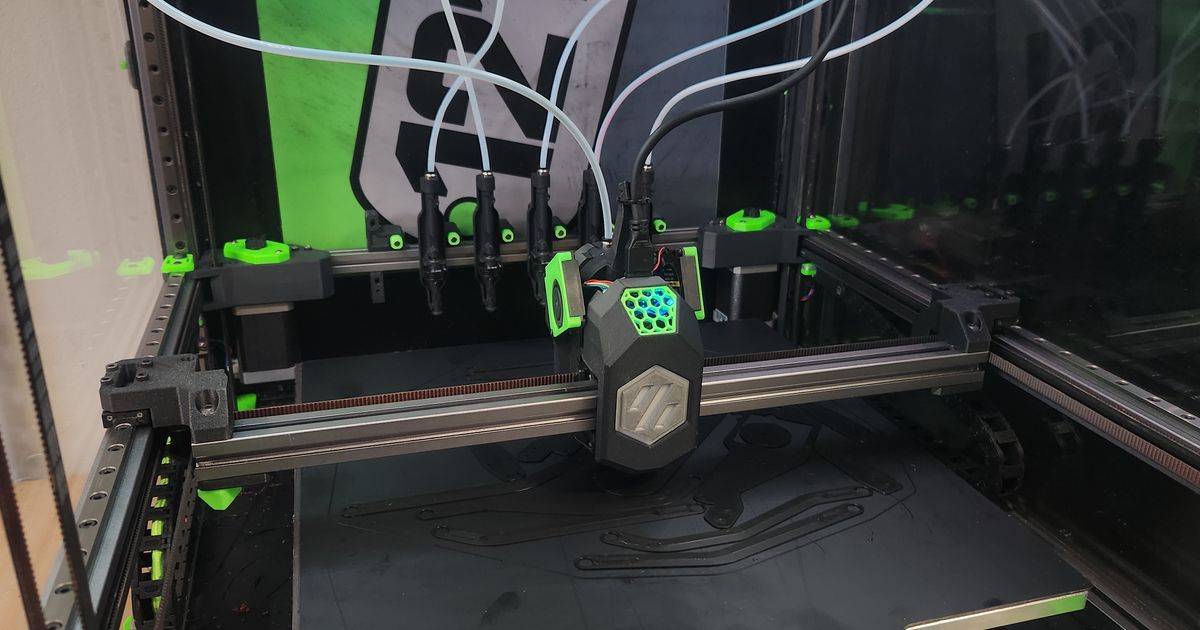
Printables.com
parts to mount indx on a v2.4 with tools in the rear | Download free 3D printable STL models
basically eliminates the need for a Z move for docking
i mean its a whole different gantry setup but it works
gritty ridge
random geode
https://www.printables.com/model/1762005-bondtech-indx-reverse-mounted-gantry-fo...
Oh..hey, thanks for sharing. That's interesting and I did not know this could be done on a 2.4. The docking bays are part of the flying gantry then. Clever
gritty ridge
random geode
im sure it could be adapted to A4T-C or other systems
Yeah, sounds like a good option for other hotend changers. My first experimental prototypes had docking bays on the front which allowed me lots of opportunity to learn and fine tune, but once I had things working well I migrated to moving the docking bays towards the back.
dusty plover
I’ve considered rear docking but am docking at the top currently like the stealthchanger to keep everything simpler. You can also mount a bar at the front of a 2.4 gantry to stow tools as well. Doing some math shows 6 tools on a 300mm 2.4 so I’m trying to target that but am currently figuring out how to get that many heaters….
Tha advantage to top mounting on a 2.4 is the free umbilical management that comes with it. Moving down gets your tool out of the way and keeps it all clean. I’ve got a different machine with 3 madmax heads at the front and while the umbilicals haven’t caused an issue I’ve had to plan out how they flex to avoid any severe crashes.
random geode
dusty plover
I’ve considered rear docking but am docking at the top currently like the stealt...
the advantage of having them on the rear bar like Hartk's example there means you could potentially just get a fatter Z chain or run 2 Z chains and have all your heater/thermistors go up that way into umbilical mounts
but different strokes for different folks as they say
gritty ridge
dusty plover
I’ve considered rear docking but am docking at the top currently like the stealt...
Can you elaborate on "figuring out how to get that many heaters…."? Are you referring to how to drive them?
dusty plover
If I run them all from the electronics bay that’s a decent idea but I’m leaning towards a Fanny pack-like solution for now
dusty plover
gritty ridge
Can you elaborate on "figuring out how to get that many heaters…."? Are you refe...
Driving them all. I’ve got 3 heater ports on my current board though one drives the lighting. I’ve got the other two wired up through the proper channels to prove this out with 2 tools. I also took the time to place the wiring for an offset probe. I need 4 more heaters and a fair bit more endstop. I can currently take a spare octopus board and mount it on the rear to give me the 4 ports, fans, thermistors, and the end stop ports I need for the docks. I’d like a dedicated board and I know some are in the works so I’m considering this a temporary evil. I’m also waiting on some parts to avoid cutting the cables on my Bambu style hotends. I want it all easy to swap out so I can place in different hotends as I like.
I even fired up kicad to see if I can make a small breakout board for each hotend but space is tight.
random geode
get an octopus pro or something? - has a lot of ports iirc
yea the octopus pro has 4 heater ports plus the bed heater output and thermistors for each - lots of fans too
gritty ridge
dusty plover
Driving them all. I’ve got 3 heater ports on my current board though one drives ...
Ah, I see. I may have already suggested this to you before. If so I apologize for repeating myself. But using Voron Klipper Expander boards are really easy to do and pretty cost effective. 3 of those boards will cost you $30US or less and that would support 6 hotends.
Plus, USB-C breakout boards and fast charge cables can make for an easy way to swap out hotend tools and simplify the wiring. But it is a bit of work
random geode
octopus pro also has a BLTouch port you can run the servo from
dusty plover
I’ve seen the usb c boards (on your YouTube) and that’s a good idea but I’m trying to avoid soldering wires on the toolhead just to make replacing stuff easier. I did look up the expander boards and I could make it work but that’s 2 more usb cables for the heaters and doesn’t solve my endstop issue and I think I’d still be short on fans.
I quickly joined the pulsar3d discord and saw the hydra expander board. That’s really what I’m looking for. The CXChanger fit has a link to a diy version of this too. I’m not experienced in pcb design enough to want to take on something like that by myself right now.
Mounting my spare octopus to the rear of the machine gives me what I need for the moment while those other projects mature.
gritty ridge
dusty plover
I’ve seen the usb c boards (on your YouTube) and that’s a good idea but I’m tryi...
Gotcha, I hear you. Its nice that you have the spare octopus board so you can get moving while those other options continue getting developed. Looking forward to your progress and updates!
Oh...hey @dusty plover before I forget, did you ever get a version of the rack that actuated the extruder tensioner arm that you wanted to share? I'm still interested in experimenting with that. On Quindec we used a second 50t gear/wheel with a cam lobe instead of a rack and I think your original experiments with the rack are still worth exploring (at least for me as I like to experiment).
empty matrix
gritty ridge
Yes, you need a movement. See this video: https://discord.com/channels/460117602...
Its just a different type of docking motion. Instead of moving along y for grabbing the tool, you "pick it up" from its resting position and "drop it down" onto it. In theory this requires less room along y between the tools, thus allowing to put more tools next to each other.
gritty ridge
empty matrix
Its just a different type of docking motion. Instead of moving along y for grabb...
Ah, thanks for describing that. I think I understand you now. So instead of the lateral (along X) movement to lock in/out the tool you can use the Z motion (drop in/out) that you might already be doing to reach a top mounted docking bay. This could even allow you to save a few mm between tools and could even lead you to squeezing in one more hotend tool if you just happened to short by a few mm
empty matrix
For my trident, I want to go with a servo actuated dock that moves all of the docked tools up/down.
gritty ridge
empty matrix
For my trident, I want to go with a servo actuated dock that moves all of the do...
Sounds interesting. Keep us posted on progress. I really enjoy seeing everyone trying different ideas and experimenting to make their own custom adaptations
versed path
random geode
the advantage of having them on the rear bar like Hartk's example there means yo...
also you can use eva/vzbot style fan ducts since there is nothing to hit except front door
dusty plover
gritty ridge
Oh...hey <@334114369384218624> before I forget, did you ever get a version of th...
I agree they’re worth exploring. I still think it can be done but my implementation kept seeing the rack slip. It worked maybe like half the time. Optimizing the angle it sits at and throwing in something that pulls it into the lgx gear as it engages might make it reliable.
I’ve integrated the servo mechanism into the cad I’m working from so I can come back to it but my desire to finish that mechanism and my desire for a running printer are in contrast. I’d like to get my 2.4 running again than maybe prototype the rack mechanism more when I can setup a dedicated testing unit rather than taking a printer down.
There’s no noteworthy updates since the cad I previously uploaded though.
gritty ridge
The TZ2 hotends arrived today. They seem fine. Heater measured at 12.2 ohms so it looks like normal 45w style heaters. These look the same as my other TZ2 hotends except the other ones I have had 85w heaters and also came with an extra cut style nozzle.
I'm actually glad these are 45w so I can compare against my other toolchanger prototypes and also not have to double up the mosfets
gritty ridge
 gritty ridge
Oh drats....I had meant to reply to your original post @dusty plover when I posted the above as these are the TZ2 hotends that you shared a link for. Thanks again for doing that
random geode
gritty ridge
which ones are these on AliE?
gritty ridge
random geode
which ones are these on AliE?
Link is in this post #1522282695516885204 message
About $6.80 iirc
random geode
gritty ridge
Link is in this post https://discord.com/channels/460117602945990666/15222826955...
ty
oh i ordered some from that same store the other day - nice
dusty plover
There’s probably some overlap in members here but armored turtle announced a hotend swapping system with more info soon.
I addition the hydra preorder went up: https://pulsar-3d.com/products/hydra
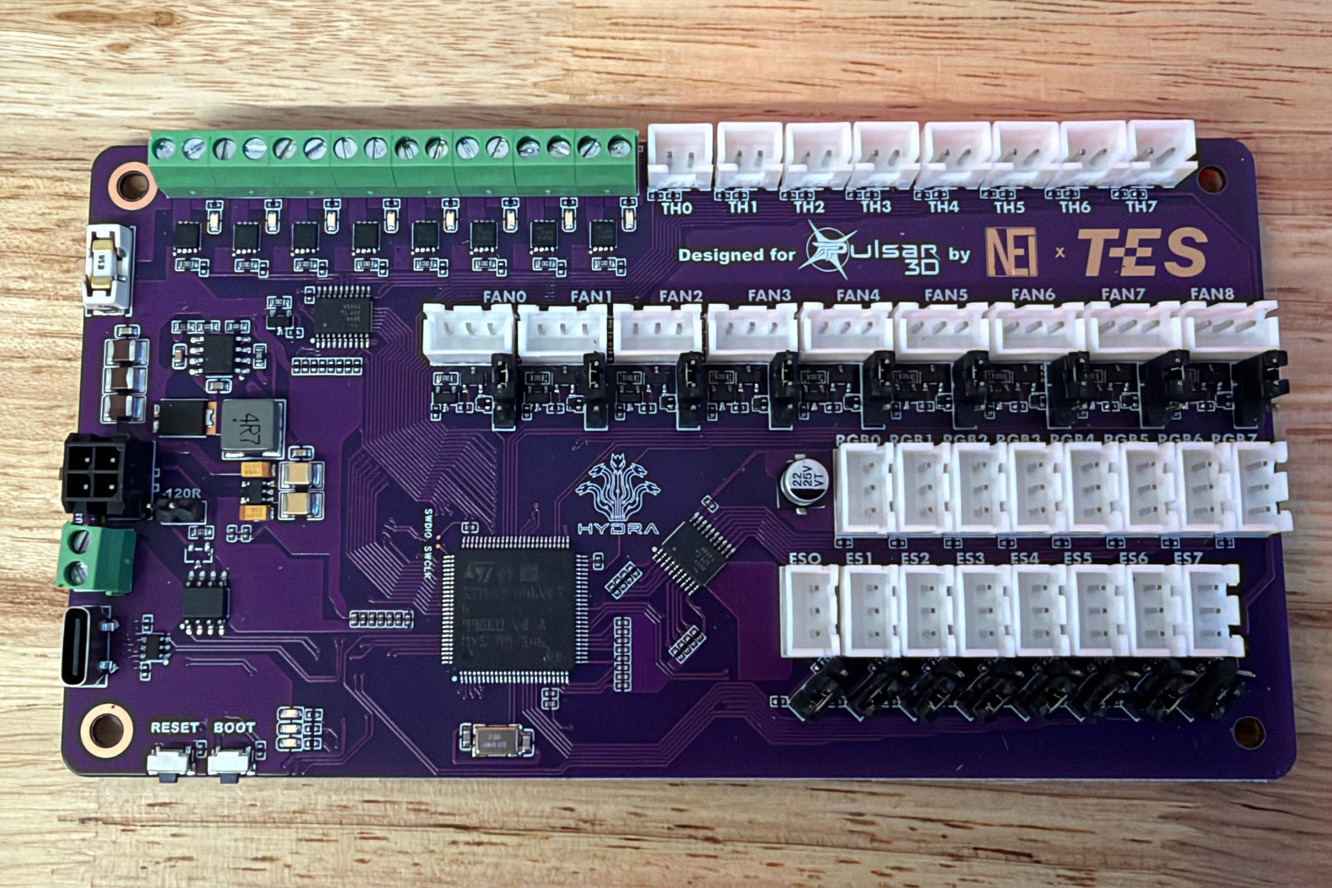
Pulsar3D
Build a multi-hotend printer with Hydra, a control board for hotend changers. Assembled in the USA. Check compatibility with your build.
urban solar
I've been waiting for that to be revealed so I could mention it here, you beat me to it lol
dusty plover

 sleek thorn
Hello! is there a GitHub repo for this project or are the info for building this spread in the thread?
shrewd surge
dusty plover
There’s probably some overlap in members here but armored turtle announced a hot...
got a link to that hotend swapping system off theirs?
<#1240479902088560690 message> ah got it
well fully 3d printed sounds .. interesting but metal is more fun 😆
random geode
dusty plover
There’s probably some overlap in members here but armored turtle announced a hot...
oh they actually have a listing now - neat
now i just need a few in Brexited to go in on a group buy 😛
cyan barn
Does A4T-C have any parts that need to be CNCed?
gritty ridge
cyan barn
Does A4T-C have any parts that need to be CNCed?
The answer may depend on which A4T-C you are thinking of. There's the original from Slimohan (still in development) which started this thread and then there are some similar designs (uses A4T part cooling I guess) that have been recently discussed and also being developed. Its unclear to me if any of these benefit from CNC parts
tawdry sleet
The amount of cables needed is insane, tomorrow I will finish the wiring and start creating the macros
 gritty ridge
tawdry sleet
The amount of cables needed is insane, tomorrow I will finish the wiring and sta...
Yes indeed.....lots and lots lots of wires. Do you have one of them wired up and tested already? I know a couple of my alpha testers wanted to wire all of the tools but I always suggest getting just at least one tested out in case something comes up. This way they don't have to try and fix the others but can instead incorporate any adjustments they learn with the first tool and add them when setting up the additional tools
molten wasp
tawdry sleet
The amount of cables needed is insane, tomorrow I will finish the wiring and sta...
@dw.tas are you planning on using a breakout board of some description, or straight connection?
tawdry sleet
My motherboard is a BTT Kraken which has most of the connections I need, and once the cables are on the frame I find it easier to go an extra 50-80cm than adding one more board, still I will have to add as an extension, I will use an old motherboard I have around, a Creality 2.2, because I need 1 more extruder slot and a few thermal probe slots, I am using a lot of them from the Kraken for heater, chamber, 2 bed probes, and I don't have enough.
 primal relic
@gritty ridge sorry if I didn't fully grasp the whole project. The a4t-c was first started by someone on now, I guess, you are the most actively developing the thing right?
If I understood correctly the tool is only held in place by some magnet and a kinematic coupling right ?
primal relic
Or maybe more @tawdry sleet 🙈 ?
gritty ridge
primal relic
<@520048236535480320> sorry if I didn't fully grasp the whole project. The a4t-c...
I am just a visitor. I tend to look for and join areas on the internet that have hotend toolchanger discussion as I find it fascinating. I've been building and developing several prototypes for the past 8 months. I think its so awesome to see all of these other designs coming together.
Slimohan originally started this thread and has a really neat design inspired by MedusaHC. His time has been limited due to other priorities but I think he's still working on it when he has time. Other participants to this thread (not me) have also shared their ideas of a hotend toolchanger (Ycsy and rilmar42 to name a few of the most recent sharings).
Many of the hotend toolchangers (including the ones in this thread) use a Maxwell coupling for the kinematic coupling with magnets to connect the two parts. Ycsy in particular has spent some solid time experimenting and fine tuning their implementation.
mortal locust
gritty ridge
I am just a visitor. I tend to look for and join areas on the internet that have...
What is the timeline for having a usable product? I have been loosely following this thread and without reading everything from the last two weeks, just would like to know the overall status of getting a custom INDX style toolchanger built. You can also tell me to read, which I am doing 😉
I am ready to build my Trident, just waiting on the "use this setup here" (example toolchanger)......
gritty ridge
mortal locust
What is the timeline for having a usable product? I have been loosely following ...
I can't speak to the status of the various A4T styled changers in this thread. Except to say that they are still being developed and not yet fully functional but look promising with each update.
There are other projects out there that are further along and functional versions up and running in case you aren't already aware of them.
mortal locust
gritty ridge
I can't speak to the status of the various A4T styled changers in this thread. E...
Thanks, honestly that is what I figured. I check this thread every few days. I love seeing all of the different setups. Looking forward to getting my SV08 and Trident setup using some kind of toolchanger. Thanks for the reply.
gritty ridge
mortal locust
Thanks, honestly that is what I figured. I check this thread every few days. I l...
Have fun. These are all really great projects. Check out Lineux HotSwap, someone just got their serial number rockin HotSwap on their Trident
 chilly breach
tawdry sleet
The amount of cables needed is insane, tomorrow I will finish the wiring and sta...
Do you guys have a github for this yet?
sturdy gazelle
A little sneak peek
 sturdy gazelle
chilly breach
Do you guys have a github for this yet?
It's coming
tawdry sleet
I finished the wiring, 2 things I learned:
- The servo works on EBB36 v1, with LEDs off and when static, but if the printer is doing anything else the power draw is too much, MG90S consumes to much from the 5V rail, causing all kind of weird issues, or even complete connection loss
- The presence switch needs a bit of redesign, it grabs the hotend mount layer lines and disintegrates on docking undocking moves (don't ask me how I know)
I ordered a MP1584EN buck converted and I plan on supplying the servo from the HE port of the EBB36 with 6V, and extra 2 grams won't be much of an issue, but the added complexity sucks a bit
chilly breach
Have you tried bending the tip of the lever slightly inwards so that it does not catch on the hotend part?
tawdry sleet
I did, that was an easy fix, for the servo I need to wait for the parts, I will work on the macros in the meantime
 teal hinge
Can you inject 5V through the EBB USB port from a dedicated supply? Or does that get messy with 24V can and 5V usb?
Would mean 1 more wire in the chain but some gland cable comes as 6 anyway
random geode
tawdry sleet
I finished the wiring, 2 things I learned:
1. The servo works on EBB36 v1, with ...
not surprised on the servo thing tbh - the toolhead boards we run weren't exactly designed to drive a servo
molten wasp
tawdry sleet
I finished the wiring, 2 things I learned:
1. The servo works on EBB36 v1, with ...
Do you think the EBB Gen2 would behave better?
random geode
molten wasp
Do you think the EBB Gen2 would behave better?
i mean it might - the Gen2 has 5v fans as an option - where as the gen1 is just 24v for fans afaik
cause for 5v fans you would have to assume they beefed up the 5v rail somewhat
chilly breach
tawdry sleet
I did, that was an easy fix, for the servo I need to wait for the parts, I will ...
Look at the Lineux btc macros as a start. I started to build this hotswap hotend changer and the dropoff and pickup works well.
I also worked on this https://github.com/JeandreCoetzer/ToolChangerDashboard which could be adapted for the A4T-C

GitHub
Contribute to JeandreCoetzer/ToolChangerDashboard development by creating an account on GitHub.
tawdry sleet
I wrote the macros they are behaving beautifully, full toolchange ~5s I can increase the speed a bit to get to 4s but it's not really worth it. The servo is still an issue I will fix it when I get the buck converter


I will upload a video in 1 sec need to cut it, it too big
random geode
tawdry sleet
I will upload a video in 1 sec need to cut it, it too big
did you see #1522282695516885204 message from Dreagor?
are you using gen1 or gen 2 ebb36's?
tawdry sleet
tawdry sleet
random geode
are you using gen1 or gen 2 ebb36's?
I am using EBB36 v1, it doesn't have enough 5V current for the servo honestly
my plan is to use that 24V->6V buck converter, power the servo from that and use the signal from the ebb36, I don't want to inject the voltage into it and pulling 1 extra wire from the mainboard is not an option either, 5V needs thicker wires than 24V, it would defeat the purpose of the EBB36
sturdy gazelle
tawdry sleet
I like your dock implementation
tawdry sleet
sturdy gazelle
I like your dock implementation
everything is controlled through hardware switches, no variables
I spent half a day on those macros but I am satisfied, I'll share them once I test with the new buck converter ETA 2 days
random geode
tawdry sleet
I am using EBB36 v1, it doesn't have enough 5V current for the servo honestly
so given that the gen2 has 5v for fans as an option do you think it'd fair better for the servo? assuming you could find enough spare IO for it
tawdry sleet
it depends because in certain conditions a MG90S servo can pull up to 2A in theory, even on v1 it works 90% of the time, so it should ... but I can't know for sure I don't have a v2
but a MP1584EN costs 1 euro, it weighs less than 2grams and for my mental sanity I would rather just use double sided tape and glue it to the servo, on top of that it can provide 6V, higher speed higher couple allowing you to tighten the screw more
random geode
so @tawdry sleet are you going to put yours up on github as a separate derivative or are you and @sturdy gazelle gonna work on merging the two? - i'm just askin questions 🙂 imo there's no right or wrong answer
sturdy gazelle
@tawdry sleet has a completely independent project, so merging is pretty unlikely. I don't think any of the parts would be interchangeable, they just kinda look the same lol. I have no objections to collaborations though, there are sooooo many good ideas in this thread and so much information.
random geode
coolio 🙂 like i said i was just askin the question 🙂 all good
tawdry sleet
honestly, I've started working on this because I liked Slimohan's photos and because my printer is very custom I am used to modding all projects or building them from scratch, I will post everything I've built here or you can attach it to Slimohan's github as an user_mod, or maybe he can integrate some of the tested ideas into his final project
viscid vale
@sturdy gazelle Are you using a Maxwell coupling in your latest revisions?
random geode
tawdry sleet
honestly, I've started working on this because I liked Slimohan's photos and bec...
sounds like a plan bud
sturdy gazelle
viscid vale
<@792573634706145290> Are you using a Maxwell coupling in your latest revisions?
It's in the works but the current design uses pins. @tawdry sleet are you using Maxwell?
sturdy gazelle
tawdry sleet
honestly, I've started working on this because I liked Slimohan's photos and bec...
I'm headed out of town until this evening but I'll shoot you a PM when I get back. You might like what I did with the extruder.
viscid vale
sturdy gazelle
It's in the works but the current design uses pins. <@212278001381933058> are yo...
I've had a look around @tawdry sleet 's CAD, and they are using a Maxwell coupling very similar to CXChanger.
viscid vale
viscid vale
I've had a look around <@212278001381933058> 's CAD, and they are using a Maxwel...
 tawdry sleet
viscid vale
I've had a look around <@212278001381933058> 's CAD, and they are using a Maxwel...
It's basically a variation of cxchanger's coupling
I've found that although in theory it would be ideal to have a magnet next to the top ball it made it impossible to build using a FDM printer, imo cxchanger design only works in aluminum cnc, in plastic, even a perfectly calibrated printer won't achieve tolerances of 0.2mm in 2 different planes on multiple assembled parts.
So, I've spread the pins and balls as far as possible, I've increased the distance between the magnets, I've made them flush with the plastic to allow regular mortal humans to assemble them and I've increased the count to compensate the fact that they were positioned centrally and with a bigger tolerance
primal relic
@tawdry sleet on the servo power issue. If you get a capacitor in the supply line of the servo motor, this might be enough. But it means you have a large enough capacitor on hand 🙃
tawdry sleet
I have a few but overall I see it as a worse compromise, at least with the buck converter I have the benefit of getting 6V out of the compromise
and the weight might actually be higher for the capacitor
chilly breach
tawdry sleet
It's basically a variation of cxchanger's coupling
I've found that although in t...
What size balls are you using? 4mm?
lost ridge
Had a dream here where slimohan pinged everyone in this channel saying that he's banning all discussion of projects that aren't his....I woke up
Strange dream but anyway I'm still so incredibly excited for these projects!
chilly breach
sturdy gazelle
A little sneak peek
Did you use the new v2 blower fans?
sturdy gazelle
chilly breach
Did you use the new v2 blower fans?
I'm using Delta fans
cyan barn
What's the nozzle swap time for A4T-C right now?
tawdry sleet
cyan barn
What's the nozzle swap time for A4T-C right now?
In the 25s video with 5 tool changes it is about 5s
After tunning and pushing the speeds up I got it to about 2s, in the attachment, analysis done by AI on the macro
I've done this mostly for testing the limits, I wouldn't run it at these speeds for day to day, squeezing out a few seconds and risking pushing the parts to close to the limit is not worth it:
- right now I'm using 300mm/s for travel towards the dock, this will most likely stay like this
- 180 mm/s for the approach/departure, this will be lowered for day to day, because if the hotend isn't docked at exactly the perfect location (0.25mm tolerance) it may push it into alignment slightly at this point and you don't want that push to be very violent
- 50 mm/s for docking maneuvers, this will also probably be lowered as well for day to day use
servo actions are done on approach and departure so that 500ms dwell time will be gone in the final macro, in the video, the speeds which are more realistic and closer to final values, are 300mm/s travel, 50mm/s approach, 20mm/s docking actions, removing/lowering the dwell time will make the final time about 4.5s
 tawdry sleet
lost ridge
Had a dream here where slimohan pinged everyone in this channel saying that he's...
You're right it is confusing for people who just read from time to time, I will finish my testing in a couple of days and I will hand over everything to Slimohan or whoever wants to take it over and I will stop the updates on this thread
molten wasp
tawdry sleet
but a MP1584EN costs 1 euro, it weighs less than 2grams and for my mental sanity...
Good idea, test the configurations first, then change the EBB later.
What size of the printer in your toolhead swap video? 5 toolheads is a good number, I'm thinking you could squeeze another 2 in there
tawdry sleet
The frame has the same sizes as an Ender 5 Plus, I just replaced the top 4 extrusions with better quality ones, it's quite big
In my build every hotend takes 60mm on the dock, but the minimum you'd need to allow the 3mm sideways move + the fans is about 52-53mm so if you want to squeeze more hotends you can, on my frame I think I can squeeze 8, but 5 feels more than enough, even with 5 I don't know where I will put the spools yet
random geode
tawdry sleet
You're right it is confusing for people who just read from time to time, I will ...
i mean i don't want to take over the project but i do wanna print it and use it 😛
it'll go on my MercOne cause its my FAFO printer bult from an E5+ like yours
 eager quest
random geode
i mean i don't want to take over the project but i do wanna print it and use it ...
same. ive been lurking for a while but slowly getting confused about what project is what and if they are "out there" in github, etc.
they have kept me interested enough that i didnt break down and buy a U1.
wooden anvil
eager quest
they have kept me interested enough that i didnt break down and buy a U1.
The u1 is on a killer sale right now and is a wonderful machine, and it's existence has really pushed forward the slicer technology for toolchangers.
My mom just bought a second one
eager quest
wooden anvil
The u1 is on a killer sale right now and is a wonderful machine, and it's existe...
my only issue with it is heating the chamber. not sure how easy it is to heat and/or insulate.
its back to $849 now that Prime Days is over, but Im sure it will go down again (BF perhaps)
wooden anvil
eager quest
my only issue with it is heating the chamber. not sure how easy it is to heat a...
Second hand experience, a friend of mine was printing voron parts with it just fine last week. He just bought the biqu lid.
I personally adapted my interruptible heat soak macro to work on the snapmaker, or the panda breath works really well apparently.
Then again, depends on what your standards are. He was comparing to an ender 3 in a tent and a voron 0.2.
eager quest
wooden anvil
Second hand experience, a friend of mine was printing voron parts with it just f...
id like to reliably print ABS/ASA with it. it would be nice to use different materials for supports so they remove easily.
i like INDX but nozzlegate is annoying, and the price just to add it onto a Voron
wooden anvil
eager quest
id like to reliably print ABS/ASA with it. it would be *nice* to use different m...
https://github.com/TheJoe1990/Tuning-Instructions/tree/main
I wrote a guide for how to use the multi material supports, is pretty cool.
I have been building an sv08 stealthchanger over the last 2 years and as I'm finishing it up I keep referencing the configurations of the U1.

GitHub
These are short guides I make mostly for my mom that may be useful for other people sometimes. - TheJoe1990/Tuning-Instructions
eager quest
wooden anvil
https://github.com/TheJoe1990/Tuning-Instructions/tree/main
I wrote a guide for...
nice, thanks!
im still trying to grasp all the various "toolchanger for voron" projects vs all the off-the-shelf type printers.
wooden anvil
eager quest
nice, thanks!
im still trying to grasp all the various "toolchanger for voron" ...
My interruptible heat soak is on there as well, that is something I've put a lot of work into and has really made printing ASA voron parts much more pleasant.
tawdry sleet
An update to the servo situation:
I got the buck converter, set it to 6V happy that this would finally complete my build, it didn't work
I figured that the 3.3V PWM signal was to low I lowered the voltage slowly until ~5.6V then it started working, but it was going very very slow, struggling to move even with no load
I thought the signal was degraded, I lowered the voltage to 5V and connected servo GND to EBB36 ground ... same behavior
I disconnected it from the buck converter and connected it directly to BTT Kraken servo port ... same behavior
The servo hasn't been moved in the last 3-4 days from the toolhead so it can't be that I force broke it.
Then it hit me, in the last few days I printed some PC-CF parts to redesign the z motor mounts to move the bed back 15mm (75C heated enclosure) and I read the MG90S specifications, it's rated up to 55C, so apparently I killed it with heat, being next to the extruder motor it probably got easily to 80-90C
I need to redesign the toolhead to find a way of opening the extruder without a servo, I want to be able to use my heated enclosure, I'm open to ideas, right now I am struggling to come up with one
random geode
tawdry sleet
An update to the servo situation:
I got the buck converter, set it to 6V happy ...
could you not use an N20 motor instead of a servo?
cause according to le google an N20 can handle up to 120c (depending on model obvs)
i mean one obvious issue is there is no encoder function by default so you'd probably need to define it as another motor and work out the forward/reverse distance to drive it and keep it super specific, also they can run on 12v not 5v (again depending on model) - but its a small lightweight(ish) option off the top fo my head
tawdry sleet
I think I will hit the same problem, I am thinking of a different approach, give me a couple of minutes I will post a few screenshots
tawdry sleet
It's just the beginning of the design, it's a rehash of my old plan to use the forward motion of the toolhead to open the extruder, before I tried the servo


 glacial monolith
High-temperature servos do exist, but most of them are expensive or large or use TTL-level UART connections instead of PWM, which is a PITA to work with in a 3D printer. The most suitable servo I have been able to find is the AGFRC B26CLM. It is rated up to 70C, has reasonable torque, is programmable (so you can disable motors at idle times), and scales up to 8.4V. I have ordered one for my own work-in-progress tool changer design (not based on A4T). I hope with an extra 2510 fan next to it it might work in a 60C chamber. I rarely push my chamber past 55C. Still probably not a solution for your 75C chamber.
tawdry sleet
it's a little monster, aside from the weight, it will need thick cables to the toolhead to power it, coreless servos use a lot more current
glacial monolith
Yes, spec is between 1.6 and 2.4 Amp loading current, depending on voltage. As long as I can keep it from stalling I should be fine with a 5 Amp buck converter in the electronics bay, with AWG 22-24 wire over the umbilical. The servo itself only has AWG 26 on its leads.
gritty ridge
tawdry sleet
An update to the servo situation:
I got the buck converter, set it to 6V happy ...
Another idea you could revisit is the method of using extruder stepper motor to open the extruder tensioner swingarm. Another gear is temporarily pressed onto the stepper so it can be engaged to open the arm. The current MedusaHC uses a servo to temporarily engage this other gear but Sergei shows an early prototype where he does without a servo by using a dock mounted bump stop to depress the gear into position.
I believe the A4T-C from @sturdy gazelle does this. And I know for sure Quindec does this. Also Dragon’s Den from Cameron Nefdt. They all do it their own way and are different but still use stepper to open the arm without using a servo.
This is also why I am interested in the rack (instead of gear) idea that @dusty plover shared as it’s another twist. It wouldn’t require a servo
wintry hazel
What about a solenoid to engage the extruder stepper to open the arm? Might take a lot less weight and energy than a servo?
gritty ridge
wintry hazel
What about a solenoid to engage the extruder stepper to open the arm? Might tak...
Worth considering for sure if you can find one that meets the criteria. But personally, I would avoid the additional electronic component and just taking advantage of the movement to the dock to depress the gear. It’s free that way and very simple
tawdry sleet
You'd need quite a big solenoid to pull the arm from 1-2mm
I've tested the arm that presses on the lever with bearing, it works, but 1st iterration angle was 45 degree 6mm forward motion to 6 mm sideways motion, and you would need to push at maximum 5mm/s to keep it from bending
wintry hazel
I wasn’t imagining the solenoid do the actual work, just change the gear path for the extruder to then do the work
tawdry sleet
6mm sideways motion = 2.5mm opening at filament level, now I've streched the arm to have a 2:1 fw to side motion 12mm:6mm and I will reprint it out of ASA
that leaves 4mm gap between the arm sticking out and the toolhead moving around when printing, but it should be enough
tawdry sleet
wintry hazel
I wasn’t imagining the solenoid do the actual work, just change the gear path fo...
it might be worth considering, right now I want to focus on my original approach to move as much weight as possible to the frame, this arm pressing on the bearing might actually work
gritty ridge
tawdry sleet
I've tested the arm that presses on the lever with bearing, it works, but 1st it...
I seem to recall the rod on the dock (that arm pushes against) also being quite long due to fans. But I might be remembering someone else’s design who had a similar issue as you
gritty ridge
tawdry sleet
I've tested the arm that presses on the lever with bearing, it works, but 1st it...
When you say “keep it from bending “ what do you mean by “it”? The tensioner arm? Or the rod on the dock?
tawdry sleet
gritty ridge
When you say “keep it from bending “ what do you mean by “it”? The tensioner arm...
I meant the rod on the dock, I replaced the long pin with a 3d printed angled twisted arm, to minimize the force needed to open the extruder and to maximize the contact with the bearing,
But still because it relies on toolhead motion you can't just ram into at at full force it will break/bend, from my testing at 20mm/s it felt too fast, I could see small bending at contact, now I changed the angle and want to try again to see how it behaves (I don't want to give up on my 5s toolchange goal)
sturdy gazelle
There's advantages and disadvantages to every design. A servo adds weight and a small amount of complexity. A pin on the dock the pushes the lever open adds a failure point if the part is strong enough. Extruder controlled openers mean you lose full retraction control, for instance if you want to unload filament. There's definitely some tradeoffs to each design.
tawdry sleet
The rod opening mechanism works much better than expected; there is no unwanted play, and the motion feels very fluid at 22.5 degrees. Who needs an extra stepper or servo when you have a CoreXY system that can push with much more force 🙂
**This will be my last update, as I've taken over Slimohan's thread long enough. ** If he wants to use anything from the project, he's more than welcome to. The macros are in an alpha state and were only used for testing. I haven't implemented per-extruder XYZ compensation yet, and they are highly specific to my build. However, anyone is free to use, improve, or take inspiration from them
sturdy gazelle
There's also a tradeoff when using the motion system to open it, you run the risk of lost steps if it binds or requires more force than planned to open the extruder. That would quickly ruin a print. Buuuut, it does clearly work
And you're free to keep on, I'm enjoying it. You have good ideas and a well thought out system @tawdry sleet
tawdry sleet
I've tested it with half current for all motors, weak enough to stop the toolhead by hand and it still worked
I think it will be fine ... time will tell
sturdy gazelle
I think it will be too. And honestly might be the most efficient way
I chose the extruder controlled route. Losing that full retraction control but shouldn't be a huge issue
urban solar
On paper at least, that does not sound like a great solution
With motion activated, you can bump the current up for the motion to unlock and then drop back to normal. AFC does that for cutters and it works quite well
tawdry sleet
The attack angle is quite low 22.5 degrees with a 6mm side motion, the force required is very low, MG90s pushing at 90 degrees could open it, this requires 4 times less force
urban solar
Oh yea, I see it. Having a hard time keeping track of which of the 3 or 4 designs going here is which.
toxic pilot
Can't you insert a longer steel pin into the printed arm to support its stiffness?
Or maybe use PET-CF or something alike. Though nice progress!
dusty plover
https://youtu.be/wiunEjQLO7o?si=ptVVURpPO-lyXHiu&t=1110 Don't know who else has seen this but Robert walks through the box turtle 1.1 stuff and at the end shows the toolchanger that armored turtle has been working on (like 18:30). It's close to the creator 5 where an extruder gear meshes with a gearset mounted to the tool. It uses pins and bushings as well.
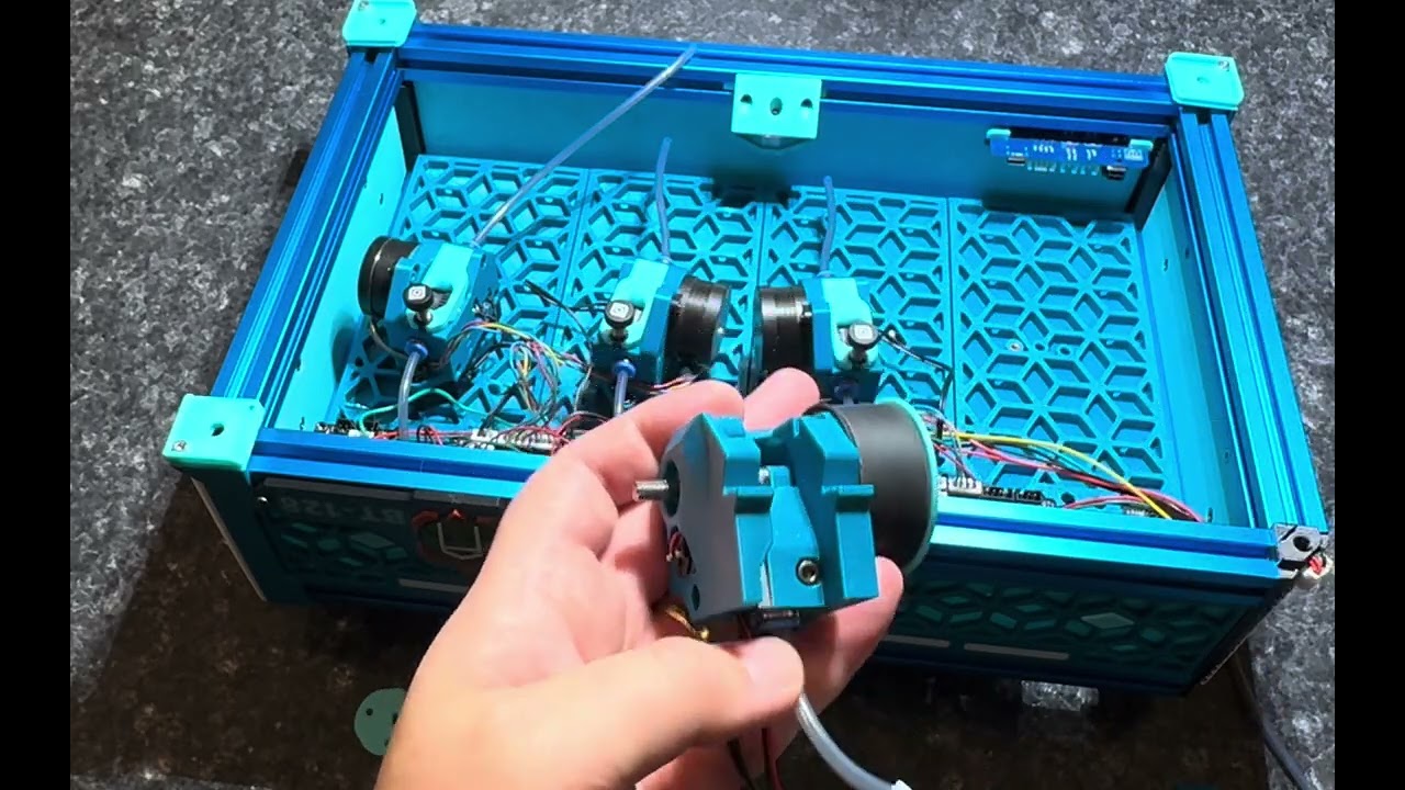
Just an overview of the changes to BoxTurtle for V1.1 and a brief preview of the AT tool changer (ATC)
AT manuals made with https://daedum.com
viscid vale
sturdy gazelle
I chose the extruder controlled route. Losing that full retraction control but s...
I'm really looking forward to seeing what you come up with
sturdy gazelle
dusty plover
https://youtu.be/wiunEjQLO7o?si=ptVVURpPO-lyXHiu&t=1110 Don't know who else has ...
I like that solution too. It's efficient and with the right gear choice it's still inexpensive
dusty plover
sturdy gazelle
I like that solution too. It's efficient and with the right gear choice it's sti...
My concern is gears lining up right but maybe they’ll come out with more info on that. I’ve ordered a similar stepper to mess around with it too as I’ve got some spare hgx gears. The hgx v2 are even smaller and I designed really compact extruders to use in a different system that might work well in something like this.
Really fun to see all the different ideas being worked on.
gritty ridge
dusty plover
My concern is gears lining up right but maybe they’ll come out with more info on...
I've not had the opportunity to see the Creator 5 first hand to see how it functions in detail but as it's already proven this type of mechanism can work I hope that this new implementation will be as successful.
 raw mirage
tawdry sleet
The rod opening mechanism works much better than expected; there is no unwanted ...
@tawdry sleet will you be creating your own thread or github or anything? I would love to continue to watch your progress on your project.
dusty plover
gritty ridge
I've not had the opportunity to see the Creator 5 first hand to see how it funct...
I’ve only gotten some idea from review videos but it’s a Maxwell coupling, and some kind of quick connector system that reminds me of a hose quick connect. In the center there’s the extruder drive pin that latches into a tools extruder gears.
From what I could see there was some play in the component that connected the extruder and gears which in guessing handles the small offsets needed based on the current gear positions.
The blackbox toolchanger project also does this.
This gear is from the blackbox project and is meant for meshing like this. https://kb-3d.com/store/motion-system/31-blackbox-igus-sls-extruder-drive-gear-1634506563098.html
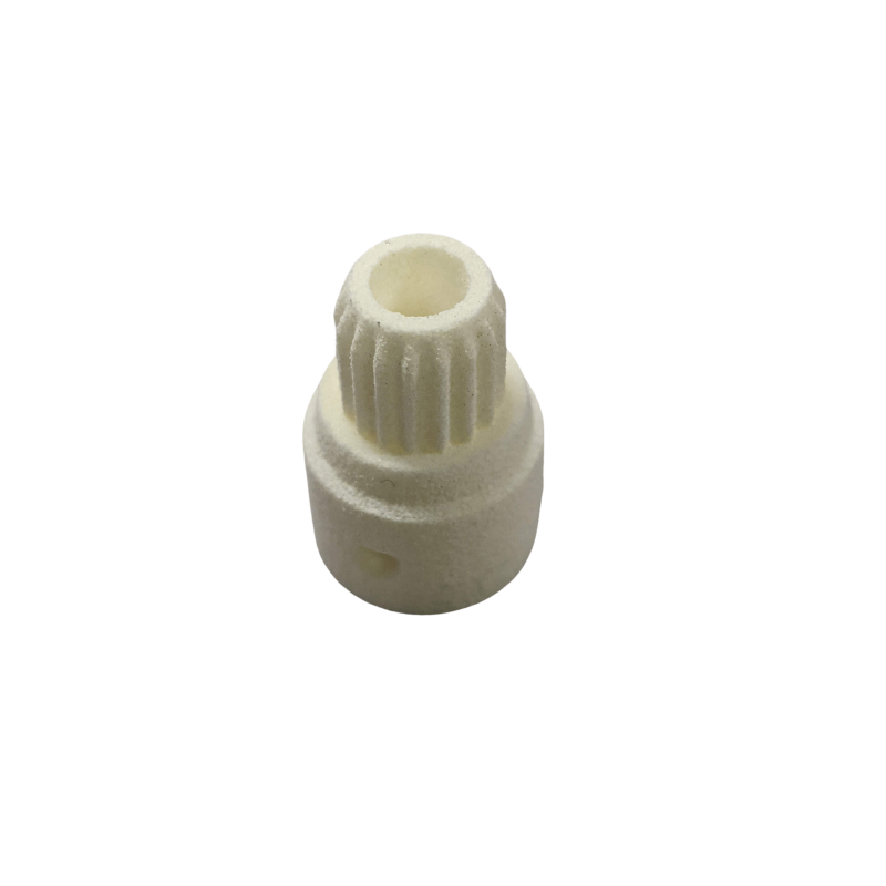
KB3D
This SLS Drive gear is produced in IGUS' Iglide material for the Blackbox tool-changing 3D printer. It allows gear mesh from any approach position.
carmine lantern
I'm considering combining a auto loading filament system with a tool changer but I haven't sorted out exactly how that'll work yet. Maybe the 3 rolls night owl mod so multiple 3 or 5kg spools can be used at once and that'll take care of the retraction when needed.
molten wasp
gritty ridge
I've not had the opportunity to see the Creator 5 first hand to see how it funct...
Instead of the gears being cylindrical, perhaps they've added a slight taper so the gear entering the housing meets the other gear which has a taper to match and they mesh under pressure
toxic pilot
Can check that as I own a Creator 5 Pro.
pure silo
sturdy gazelle
I chose the extruder controlled route. Losing that full retraction control but s...
I'm a little confused. Didn't you use a disconnect mechanism for the unlocking? That would allow to retain full extruder control as long as unlock gear is not engaged? Or did you change that design? I finally got my fully functioning with the extruder and docking/undocking. Extruder only locks in when at the dock and retains full functionality otherwise. 4mm retract to unlock the extruder, after approx 1mm it's released enough pressure that it not longer moves the filament.
gritty ridge
pure silo
I'm a little confused. Didn't you use a disconnect mechanism for the unlocking? ...
Yeah, I picked up on that too. With Quindec you can retract at any time except for when you are actuating the tensioner arm to open it (for tool change).
Unlike with YUDX where you are limited to how much you can retract during a print.
So I suspect there's something I (we) are missing
sturdy gazelle
pure silo
I'm a little confused. Didn't you use a disconnect mechanism for the unlocking? ...
There's been a change. I opted to use a one way bearing instead of the magnets.
pure silo
sturdy gazelle
There's been a change. I opted to use a one way bearing instead of the magnets.
I'm slightly disaapointed🤣 but I get it. I assume you found an issue and that's the solution
sturdy gazelle
Not necessarily an issue, but just making it a little bit simpler
You think I should stick with the previous design?
urban solar
I have concerns about long term reliability. The one way bearings used in the filamentalist are known to seize up
sturdy gazelle
urban solar
I have concerns about long term reliability. The one way bearings used in the fi...
That's not something I was aware of
I'm using the OWC511 GXRZ bearing
urban solar
I think they are fairly similar internally? I don't know enough specifics, not my area of experience, other than seeing the one from filamentalist fail
sturdy gazelle
That's good information. The previous design still exists, it wouldn't be an issue to keep on with that.
Wait, is it a printable bearing?
urban solar
no
sturdy gazelle
Ok, I just pulled specs on it. They're the same but different. The one I went with is used in fishing reels, so it's typically being spun at high speeds. In the case of the extruder it's moving pretty slow
gritty ridge
urban solar
I think they are fairly similar internally? I don't know enough specifics, not m...
Can you provide more detail about this "known to fail"? It would be helpful to know the frequency of this failure or how prevalent it is or if it was a reported issue on just one or two builds or something else
sturdy gazelle
I do have a question for the masses, is the loss of full retraction control a major issue? If it is then I'll just use the magnetic cam actuator and ditch the one way bearing.
urban solar
I feel like it is. I know I retract a decent amount at the end of prints 🤷♂️
wintry hazel
I retract 10mm on my Dragon UHF at print end. It lets me pull the filament out later when everything is cold, I really appreciate that. It wouldn’t be the end of the world if I could not, but it’s nice
amber plaza
sturdy gazelle
I do have a question for the masses, is the loss of full retraction control a ma...
That depends on what degree of control we’d be losing, I feel.
sturdy gazelle
amber plaza
That depends on what degree of control we’d be losing, I feel.
The bearing locks up pretty fast
Might get 10 ish mm of retraction before the cam fully opens the lever
amber plaza
sturdy gazelle
Might get 10 ish mm of retraction before the cam fully opens the lever
That’s honestly not that bad at all, iirc PETG needs the highest retraction distance and that’s only a few mm
sturdy gazelle
Oh it won't affect printing at all, I made sure of that. The only thing it really affects is if you want to do a full retraction to unload the tool
amber plaza
sturdy gazelle
Oh it won't affect printing at all, I made sure of that. The only thing it reall...
So what would someone do in order to unload the tool and not cause the CAM to open the lever?
sturdy gazelle
amber plaza
So what would someone do in order to unload the tool and not cause the CAM to op...
Ummm, good question lol.
amber plaza
sturdy gazelle
Ummm, good question lol.
Disposable toolheads? I’m sure you’ll figure it out
sturdy gazelle
amber plaza
Disposable toolheads? <:heh:996820360475459644> I’m sure you’ll figure it out
I have a couple ideas, one of them being staying with the magnetic actuator. I was hoping to avoid having to rely on a pin or something on the dock to interface with the toolhead at all but it may be unavoidable.
amber plaza
sturdy gazelle
I have a couple ideas, one of them being staying with the magnetic actuator. I w...
Why would a pin (or something) on the dock be a bad thing? I’m a civil engineer, not mechanical, so I know very little about making things that are designed to move lol
sturdy gazelle
It's just another failure point. The less things the toolhead has to interact with the better. But sometimes there's no getting around it, especially when you're trying to keep things as simple as possible.
cosmic plover
sturdy gazelle
I do have a question for the masses, is the loss of full retraction control a ma...
I do like the one-way bearing approach. In my experience I've never needed more than 1mm for retract, and typically run between .2 and .6mm. It will retract when it's docked which is beneficial for ooze prevention, and it allows the tool to be commanded to let go at any point and not just at the dock for maintenance.
I don't know if there is enough travel for tip forming for unloading though. That can always happen when docked by cutting the filament with flush-cutters where the extruder grabs.
pure silo
sturdy gazelle
I do have a question for the masses, is the loss of full retraction control a ma...
I think it depends. Technically you should never need to retract more than your printing retractions. Only time would be unloading filament which is kinda null for a hotend changer because you can just remove the hotend and pull out the filament. Just monitor the amount of retraction it would take before the bearing locks up and starts opening the extruder arm. On mine it takes about 4mm retraction to fully open but a little less than 1mm before the filament is no longer grabbed enough to be pulling it back. If it takes too much retraction you could be pulling the filament out of the heat zone and cause the molten tip to be stuck in the heatbreak
empty matrix
Also I would always opt for an active spool managemen or multi material system. Thus its motors can take care of unloading.
pure silo
DragonsDen is officially printing!
random geode
pure silo
DragonsDen is officially printing!
ooo very nice bud
raw mirage
pure silo
DragonsDen is officially printing!
Great job, looks amazing! How soon before you think you're ready to share the files?
pure silo
raw mirage
Great job, looks amazing! How soon before you think you're ready to share the fi...
Depends show time goes. I need to go through my config setup and make it a bit better as well as some of my patching for tool pickup etc. Toolchanges are 15s from print stop to print start. Can definitely be made faster
thick shale
why is it called dragonsden?
raw mirage
thick shale
why is it called dragonsden?
I can't speak for Cameron, but I'd assume it's cause he's based his design off of the Dragonburner toolhead.
urban solar
pure silo
Depends show time goes. I need to go through my config setup and make it a bit b...
15 seconds? the horror. *looks at my 1:30 mmu changes" lol
pure silo
urban solar
15 seconds? the horror. *looks at my 1:30 mmu changes" lol
Hahaha, yea my CAMMU MMU that I designed was approx 1min on changes. 30s to unload, 30s to load
urban solar
add in cut and purge, and you're not far off
 waxen parcel
raw mirage
I can't speak for Cameron, but I'd assume it's cause he's based his design off o...
Wait I am a little lost here, isn't this supposed to be an A4T based changer?
urban solar
Different project.
raw mirage
There are a couple different projects all floating around in here. Lol
waxen parcel
Ahh ok that makes sense because I double checked I was in the A4T-C thread 😅
 hearty oyster
btw dumb question: Is it x1c hotend because other ones wouldn't rlly work or just because?
toxic pilot
It is small, cheap and available.
sturdy gazelle
waxen parcel
Wait I am a little lost here, isn't this supposed to be an A4T based changer?
This thread has kinda become a hub for a few different projects, and I welcome it lol. I love seeing all the innovation and ideas people have. And all the different takes on achieving the goal.
Maybe I should rename the thread to the Voron Tool Changer Hub
urban solar
Hotend changer hub. to differentiate it from full toolhead changers?
elfin ice
As I’m preparing to order some of the required stuff, Is there a special board u guys use to have 8 heaters and thermistors? I’m still running on 2x skr1.4turbo 🙂
raw mirage
sturdy gazelle
This thread has kinda become a hub for a few different projects, and I welcome i...
I'm loving watching the different projects develop. Just trying to figure out which one I'm going to go with now. Lol
sturdy gazelle
raw mirage
I'm loving watching the different projects develop. Just trying to figure out wh...
Me too!! Wait....
dusty plover
elfin ice
As I’m preparing to order some of the required stuff, Is there a special board u...
The hydra board over on pulsar3d (and maybe sold on nameless engineering, I forget) is designed to tackle this. Not sure when it’s shipping though.
sturdy gazelle
dusty plover
The hydra board over on pulsar3d (and maybe sold on nameless engineering, I forg...
I saw that, it's pretty cool. I have something else in mind to use though. That's all I'm going to say 🤫
dusty plover
 elfin ice
sturdy gazelle
I saw that, it's pretty cool. I have something else in mind to use though. That'...
I just want to preorder first? 😉
glacial monolith
My plan for 8 heaters and thermistors is to just get another Octopus Pro 1.1, in addition to the one I have. Each one has room for 5 heaters and thermistors, leaving two spare for heatbed and LEDs. That board is only slightly more expensive than the Hydra, available now, and works very well.
dusty plover
I think you can use klipper expanders for a few extra hotends and fans as long as they’re within a certain wattage, adds a few thermistors as well.
sturdy gazelle
I will neither confirm nor deny that something may be soon available that will solve all these problems that is not the Hydra board.
elfin ice
Can u quantify soon?
Like soon u might get it before Christmas holiday where I might get some time to tinker around?
sturdy gazelle
That's all I'll say
 sturdy gazelle
 elfin ice
While calibrating my ercf I changed to EMU which is not finished till Christmas;-)
sturdy gazelle
My wife bought me a Box Turtle for my birthday over 2 years ago, it's still in the box lol
elfin ice
 raw mirage
sturdy gazelle
That's all I'll say
Looks great/exciting! Can't wait for you to share more! Can't wait for you to share your files for the toolhead as well. I'm currently printing some of YCSY's latest iteration to play around with, but I'd love to be able to print yours as well to compare.
cosmic plover
pure silo
Hahaha, yea my CAMMU MMU that I designed was approx 1min on changes. 30s to unlo...
Cries in Qidi Box
elfin ice
@potent yoke sorry you see this half build EMU, the 2 lanes are working fine, parts for filamentalists are ready but not build. Other housing parts are in printing queue, but i underestimated the printing time required 🙂
potent yoke
elfin ice
<@1020617964732555306> sorry you see this half build EMU, the 2 lanes are workin...
Don't be sorry, I love seeing EMUs in the wild. I might be just slightly biased, but I think everyone should have one 😄
toxic pilot
sturdy gazelle
My wife bought me a Box Turtle for my birthday over 2 years ago, it's still in t...
Is it called Box Turtle because of that? 🤣 🐢
hearty oyster
toxic pilot
It is small, cheap and available.
i don't really like it being on the lower end of flow rate
random geode
hearty oyster
i don't really like it being on the lower end of flow rate
well feel free to design your own with chube compacts or whatever - but you gotta remember that the faster you go the more likely the tool is to come loose when changing directions and shiz
hearty oyster
random geode
well feel free to design your own with chube compacts or whatever - but you gott...
yea true, seems like you will have to do compromises anyways
random geode
even on full toolchangers you wont see them going stupid fast - the prusa XL has the most secure locking afaik but even that doesnt go mega fast
trade offs
mutli-colour/multi-material or speed - you cant really do both due to the need to change tools
i mean you can get a toolchanger to go fast(ish) but there will be a limit for sure - and you'll probably hit the motion limit before you hit a flow rate one
hearty oyster
random geode
i mean you can get a toolchanger to go fast(ish) but there will be a limit for s...
i mean x1c hotend is just about 230 mm/s
dense stirrup
hearty oyster
i mean x1c hotend is just about 230 mm/s
Be careful with that thinking. It is more about the nozzle diameter 😉
urban solar
There are reasons to not want a bambu hotend beyond flow. They're limited to 300c, what if I want to print materials hotter than that? Also, the x1c mount is problematic into plastic in my experience. TZv6 2.0 is just as cheap but in a more conventional package
hearty oyster
damn 12 for a hotend that seems this good
 urban solar
I'd spend a little more and get a slightly more reputable one, with the 80w heater, but they are really good for the price
hearty oyster
urban solar
I'd spend a little more and get a slightly more reputable one, with the 80w heat...
yea would be nice for toolchanger type of things
urban solar
Yea, one high performance hotend, and a bunch of those
hearty oyster
urban solar
Yea, one high performance hotend, and a bunch of those
i have a phateus hotend for ad5m and it does like 50mm^3 asa and i would want to reuse it lol
but it doesn't seem like it would be good for nozzlechanger

probably should leave the channel as a4t-c and not random hotends
urban solar
Well the regular a4t supports a bunch of different ones, I have a chube compact and a dragon uhf mini on my printers, both in a4t
hearty oyster
urban solar
Well the regular a4t supports a bunch of different ones, I have a chube compact ...
i mean that nozzle/hotend changers would probably work better with square type of hotends
i would like to design a month for that hotend for a4t later tho
random geode
urban solar
Well the regular a4t supports a bunch of different ones, I have a chube compact ...
yes but this is A4T-C a hotend changer based on A4T - it's got nothing to do with the original author at this point - im sure other hotends will be made by other people but for now its bambu X1 based - its all mostly to do with what'll fit in the new hotend changer path - a TZ-V6 might fit but it all just depends what the spacing is like now between the filament path and the hotend cooling fan - cause there's now tool changer stuff in there taking up space
urban solar
random geode
yes but this is A4T-C a hotend changer based on A4T - it's got nothing to do wit...
dusty plover
I hope @sturdy gazelle doesn’t mind other project updates but I made another thing based off @tawdry sleet s Maxwell coupling and the armored turtle idea of using a bondtech 17t motor gear.
Currently testing a bit more, cleaning up wiring, and waiting on more gear sets to get another tool.
If this is too off track for this thread I’ll spin up another one if it proves a fruitful endeavor.
sturdy gazelle
dusty plover
If this is too off track for this thread I’ll spin up another one if it proves a...
Post away! This has kind of become a bit of a central location for a lot of projects, not just mine.
Excellent work btw!
viscid vale
dusty plover
I hope <@792573634706145290> doesn’t mind other project updates but I made anoth...
Do you have a dock to test docking/undocking?
That looks really cool
gritty ridge
hearty oyster
damn 12 for a hotend that seems this good
If you look around the X1C clones can sometimes be purchased for under $7US from AliExpress. These are complete hotends with thermistor and heater.
I scored earlier back in March and picked up about 20 TZ2 Bambu clone hotends for $9US and they all had 80w heaters.
These are great hotends for toolchangers
See this: #1522282695516885204 message
dusty plover
viscid vale
Do you have a dock to test docking/undocking?
I've got a dock at the top of my 2.4 since that seems like the lowest barrier to getting something working. I have a wire cover that contains the docking screws that I need to get on but my connectors are a bit thicker than I anticipated so I was struggling on initial assembly.
I'll try docking at some point but I'm trying to verify it even works. Tolerances got a bit tight so I had to reduce the size of a few magnets.
empty matrix
There just so many tool changer designs in the works currently Dx So many news to track and its so difficult to decide on one
shrewd surge
empty matrix
There just so many tool changer designs in the works currently Dx So many news t...
give it all half a year then then there are gonna be a couple stable and reliable once.
empty matrix
But I want to have it now! I'll just design my own with drugs and fun
random geode
empty matrix
But I want to have it now! I'll just design my own with drugs and fun
don't forget the blackjack and hookers
sturdy gazelle
empty matrix
But I want to have it now! I'll just design my own with drugs and fun
YUDX tool changer kits are available on AliExpress
cyan barn
True
dusty plover
I’m working on macros to enable extrusion with a shared motor but I’ve seemingly gotten a reliable docking procedure although the docks are barebones.
 midnight stone
Hi y’all. May I ask what the status of the project is right now? Is there a working variant?
I’m considering to try this project on my 2.4 with the next rebuild.
I don’t want to rush, I’m just super curious 🙂
 gloomy sun
dusty plover
I’m working on macros to enable extrusion with a shared motor but I’ve seemingly...
There is a reason for coupling with X. Movement or I could use z as well?
urban solar
Probably so it works on a trident as well?
dusty plover
gloomy sun
There is a reason for coupling with X. Movement or I could use z as well?
X works universally. You could move in z before undocking and it would save some space. This is just how I got it working since I had a 1515 extrusion dock laying around from when I thought I’d install indx.
I’d need to move docks above or below the extrusion for a z dock movement. It’s on the list but this was the lowest hanging fruit.
I also want to rework the part cooling to minify the toolhead and be able to make smaller tools as a result. This would also get rid of the last part that’s derived from A4T 🙃
Looking up sim tutorials while I wait on some parts.
gloomy sun
dusty plover
X works universally. You could move in z before undocking and it would save some...
So you could use this kind of latch, I mean, your dock undock is only due the magnet attraction right?
 midnight latch
gloomy sun
So you could use this kind of latch, I mean, your dock undock is only due the ma...
You can use push-pish latches but they lose travel and you need them both to attach perfectly. I abandoned them for MadMax for this reason.