#Nitro Voron 2.4
1 messages · Page 2 of 1


You have them the right way in this picture,
Now point the side that has the black screw towards the front of the printer
Unless I'm just being overly gentle with the wires
I find it easier to kinda hold the wires with one hand, close the assembly with a bit of tention, and sandwich it
Making sure not to pinch anything in the process


You could also rotate the heater cartridge to make it easier but shouldn't matter all that much
The heater block REALLY wants to unscrew. It takes zero effort
You'll have to make that tighter
I don't see a screw for it
Well, it kinda is the screw..
You could loosen that assembly, and try and turn it against the heat sync, I think that's what I did
You just have to watch your nozzle length and make sure it's got enough sticking out

This hotends seen some shit 


Nice!

It does! That's for the fillament sensor which sucks, I'd go ahead and pop it out of the tap harness and put it with the sensor in case you decide to install it somewhere else
If you're not comfortable with doing that, just tuck the extra wires in there , it's kinda tight but it does fit
Hmm...haven't even seen anything about the filament sensor yet
It's been sitting here the whole time but haven't seen anything about it in docs
That's because it says nothing, I had to jump through hoops to get mine working and couldn't even get it working on that pin, had to use a different one
And... It sucks. Lots of resistance, it's made out of the esun abs+ that will melt in chamber temp
Rip
I was hoping to have a filament run out sensor
You can use that one, just I wouldn use it there...


This is the intended purpose


This routing for the x end stop seems...suboptimal...

There's a channel for the wires to go into under the switch

Ahhhh..
I hate having to bend these wires at extreme angles like this
It's got heat shrink on it preventing the bend
Generally once or twice is fine
Lol make a little loop if you have to

Been working fine for months
Trying to figure out how to stuff the cables under the cover 😅
Good luck
Lmao
I found that generally you can kinda lay one over another but no more than 2 time, just make sure the screw hole is clear
Could have to deal with this.

Idk how this is possibly supposed to fit over the toolhead PCB

Remove that zip tie, lay everything out as flat as you can get it

The alignment between the front piece and toolhead board is...not great..

I can get it to mesh together with some force but it feels wrong
Have to like pull down on the front and push at the same time
Double check alignment, it shouldn't take force but it may take pursuasion
Oh dude that's fine
Glad I noticed this now

Are they really wanting me to cut and strip this cable myself 😳🤣

I can do it no prob but geez
Boom

Tomorrow is wiring..
I did a lot of that tonight lol
Oh man, please print and install this https://www.printables.com/model/642001-voron-stealthburner-sb2209-sb2040-misalignment-pro

Ok lol
I have seen quite a few of them go up in smoke because of misalignment. This will prevent you from becoming one of the casualties
Thanks homie
@jade citrus is the file available for that filament run out sensor so I could just print it with my own filament so it doesn't melt?

If you insist on using a runout sensor, I would place it outside the chamber. Personally I hate them.
I don't let it run out. LOL
I weigh my spools when new, so I can just grab a random spool and know I have at least enough to finish the job. I do use the box turtle at times for runout, but thats only when I am cleaing out a bunch of partial spools
Yeah but the box turtle needs some kind of "trigger" to know the filament loaded
How do you do that?
You use ramming?
I use ramming, but others use filament detection sensors. I have used them in the past but they were a bit unreliable.
Oh my plus4 the run out sensor acts as the detection sensor as well. I think the filamatrix has a built in sensor...they might be the best option
Filamatrix is definitely the best option if you are planning on a box turtle. at least starting out.
If you need a sensor right at the toolhead SB had a collection of parts called "fillamatrix" and it's got a sensor built into CW2
Filamatrix is different from fillamatrix?
filametrix is different from FilamATrix. the latter is the one updated and supported by the boxturtle crew
I'd like to go stealthchanger.
"Go with"? are you dating it? 😛
I might
With how much money you'd have to throw her way I'd be concerned about how one sided the relationship would be 
😭😳
Does tap work with stealthchanger?
Would I need a tap for each head?
Did I already ask this
stealthchanger requires TAP. it is a different shuttle and carriage though.
And it is quite nice upgrade
This is the one that I have. https://www.aliexpress.us/item/3256808225451808.html It is decent. Even if you are not building a toolchanger, it is nice because you can swap your toolhead without using any tools
How much of a pain is it? Doesn't seem like a 2nd toolhead would be too expensive.. don't need another toolhead PCB do I?
You would need another toolhead pcb, you need an entire second toolhead, an alignment endstop like the sexball, and a lot of patience. It is still a worthwhile change to that shuttle even if you never do automatic toolchanges though
I think the micron would be an awesome little multicolor machine
Sexball??? Helllll yeah I'm in
Mine is getting some toolchanging here soon
I gotta try getting 1 working first...
I hope I wired everything right in the toolhead lmao..
Gonna double check when I get home. Don't want magic smoke
Me too
Then gotta do the whole electronics bay
Take lots of pictures and ask lots of questions if needed. Nobody here minds at all
As long as y'all are around later 🤣
Kinda weird how I have to jump between multiple manuals for everything
I know it feels that way but it makes sense when you think about what is truly stock on these machines. Yours is far from stock even though it is a very common build
And the fan jumpers are set to 24v
the on, on, off, on relates to page 13 here https://github.com/bigtreetech/EBB/blob/master/EBB SB2209 CAN (RP2040)/Build Guide/EBB SB2209 CAN V1.0(RP2040)Build Guide_20250508.pdf

GitHub
Contribute to bigtreetech/EBB development by creating an account on GitHub.
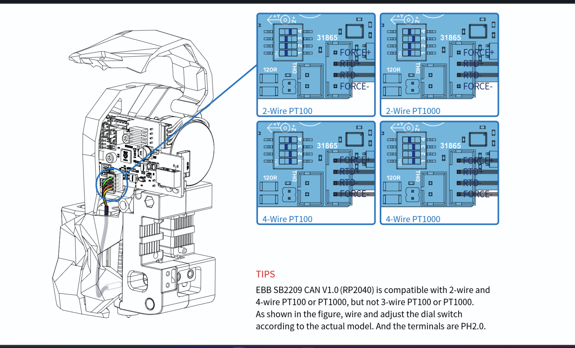
Did you say you have a pt 100? Switches should be on on on off. Top left pic

Cool.
also.. they gave me a PG7 mount STL and umbilical thing but I heard PG7 is bad?
Not bad. Bonkers to suggest it is bad as well. 😂 PUG’s benefit is that clamps around the cable instead of sliding over it. That means you have to depin the canbus cable if it has connectors on each end already
I mean from your description it kinda sounds bad
The are more flexible than the pugs. Just different
Sooo are the PUGs printed?
PG7 is great for cables not already terminated. PUG is great for cables already terminated.
It’s in the name. 
TPU im guessing?
I have some in abs
Technically. It’s not. https://www.printables.com/model/378567-pug-parametric-umbilical-gland

That’s why I always have so much difficulty finding them then
You would be surprised how flexible a print in ABS can be.
So should I just print in ASA then? (i dont have abs) I also have tpu but..
You absolutely can. And I would. TPU might actually be too flexible depending on your chamber temp. Lol
Same thing in this case
dope
jesus christ there are so many options
which one do i want???
I will let @boreal marsh answer getting ready for dinner
I would answer but my phone doesn’t like that printables page…
oof
7mm zip tie medium or maybe 5mm
Basically. You’ll want to measure the thickness of your cable to get the inner diameter of the PUG, then it’s really up to you on how long you want it to be.
Personally I would just use the pg7 you already have
deadass?
If you’ve got it might as well use it.
And already have the parts printed for it

It’s easy to replace later. You just snip the old one off
Correct
You will have to depin that JST-XH connector to fit it through the PG7
You just press the little tab down and pull the crimp out. It’s super easy.
depinning connectors is always sketchy cause the pins can break off so easily
well the retaining hooks
Not when crimped correctly. I’ve yet to break one.
So..

My tap is the 5 wire one on top and the limit switch is the 2 wire one to the bottom left of it

My connectors have different pin counts ofc
You’re looking at the wrong SB2209 manual.
Ope
GitHub
Contribute to bigtreetech/EBB development by creating an account on GitHub.
You need the RP2040 one. Not the older STM32 one.
Yeah
I looked it up on Google instead of following the formbot link on GitHub this time. I did follow the right one up till now lmao
lol. Fair. If you look it up again just be sure to search for BTT SB2209/RP2040
My CB1 does NOT want to plug into the manta
Feel like I'm gonna break kt
Can only get one side to clip in at a time
Might be worth a post in #voron_electronics not familiar with those boards
@jade citrus did u have this issue?
im pretty familiar with pc componets ans tiny button style connectors, its kinda like a big one of those, id just lightly get it lined up on there, wiggle it a little bit ( with essentially zero force downward) and itll kinda find its place, should be able to use 1-2 fingers with light amount of force to click it into place , you may have to kinda "shimmy" it evr so slightly as you go
should not require much force at all.
I tried that... It takes quite a bit of force to even get 1 side to clip in..
is it lined up all the way?
mine didnt take a whole bunch of force, wouldnt hurt to ask in the channel that wheels reccomended
There is also a ping for more eyes
man id rather have thse issues than trying to figure out uart on an uncooperative skr mini XD
I did alrdy, nothing yet
It can take a little time, be patient. It’s better than breaking something
absolutley
im pretty sure ive been destructive enough today, hell i just opened a help ticket
Yes, @odd dew a help ticket is always an option as well.
Most ppl will just say "mine went right in like a hotdog down a hallway!"
Maybe I gotta spit on it
Or patience. There is plenty of stuff to mount and wire up while waiting
Alright back to building. 😂
Yuppp
Idk what motherboard mounts I'm even supposed to use. There were a couple different kinds in the files..

All I know is these mounts really wanna strip under very light tension from the screws
Probably related to a slight dimensional issue with the print. If you have m3 hardware, you can always run bolts through and put nuts on the other side.
Under normal use, there is only the weight of the board, so it doesn’t need to be super tight
Sometimes. Sometimes they are mirrored, sometimes they are completely different. Those look in line though, so you should be good to go
The slots are there so you can adjust the part that clips onto the din rail. Slide them until they are centered

They're fixed
No sliding
Not sure what their plan was there. Maybe pick the one that is closest to centered and print a copy? Lack of knowledge on that board is a bit limiting
I am heading to bed. Good luck!
@jade citrus how'd u stop the PSU sliding down the din rail?
There's a PSU support bracket in the files that I printed but it seems to be for the stock rail orientation
i just vhb taped taht bracket i think
To what lmao
the bottom panel
i dont remember tbh lol
its supposed to stick out and attach to the 2020
yeahid just find a non destructive way to mount it somewhat in place
Hmm..
Ending it here for the night


Looks good to me!
Are you grounded to the case of the PSU? And the frame in some way shape or form?
There's one ground strap labeled "frame' I believe
Where's the best spot to ground to the frame? Surely grounding through the anodization isn't great
youll have to scrats a spot off to bare metal to do it right
the biggest concerns is all the stuff in close prximity to mains, to keep you from being electricuted in the case of a short to the frame
I don't think I see a frame ground..? Or a psu one

Sure you can, under the board into the channel, to the front and over
Hmmm....
My wiring look correct? I'm pretty sure it is..
I'm confused on how to hook up this z chain and pg7 mount and can't find anything in the manual
Do I have the wrong cable bridge? Don't see a way to mount the pg7. I do also have this piece but I don't see a way to connect it


Do I actually need this one? https://www.printables.com/model/463220-voron-cw2-stealthburner-ebb-sb2240-pg7-umbilical-m/files
The cable bridge in the formbot kit is ass. Though, the one you linked actually allows you to screw it in.
I think the intent is to not use the nut
I would advise you slip on both pg7s before managing the cable.
I don't understand why it includes those 2 files, I see no way of mounting the one I was holding there.
And the first one doesn't have a pg7 mount
There is another piece to the first that grips the connector directly, but not the pg7
I have the piece for the other end that screws to the top of the A drive with the pg7
So that end should be ok.
Do you have access to a printer?
the one on the right is for the ab drives , the one on the left has a second peice that just grabs the btt cable, and yes, its trash
Personally, this is the one i like
https://www.printables.com/model/566805-sb2209-pg7-stealthburner-mount/collections
that one works well
Had to dig the file out of the abyss, sorry.
the one he linked is what ive been using for a while, its the first abs print i ever did lol
Cutout or no cutout?
If you want to change it later, cutout.
Alright
cutout lets you run the cable through as you please, no cutout will require it to be fed throlugh it first
Choice seems obvious then
I did cutout cause i swapped from stock.
the cutout version works fine btw , no difference in stability
My graphs look interesting but normal.
i killed alot of hardware last night but im finnaly moving away from SB
whats the best print orientation for this thing

like that, whats the extra bit?
misalignment protector
not familiar with that one
Probably for the toolhead board
oh nice!
You should have like, a bunch more wire channels
And I don't remember exactly but the z drive wires may be of different lengths
Same length. And there are a couple more channels but these mfs are LOOOONG
I just finished my formbot 2.4 350 not too long ago, and the big thing I recommend is just skipping the cb1
I just ran that one under the board into the channel behind it
I cut my channels with a dremel
?
The double sided tape they provided ripped the top layer off my laminate dining room table...
That shit ain't coming off 💀
Gotta find places to put them lol
Yeah I purposefully didn't run the tape along the whole thing
I wasn't expecting it to be that strong


GitHub
Contribute to FORMBOT/Voron-2.4 development by creating an account on GitHub.
But anyways yeah. If you have another raspberry pi on hand, just use that from the start
See there's a HOLE in the middle there idk how they managed to get a channel over the hole that has wires coming through
It's not
I only have 2 pis, both in use by other printers..
I just cut the channel so it ended before the hole
What issue did u have with the CB1?
My cb1 kept dieing randomly
Oof
You might have more luck but yeah
Did u use the steel wire for the umbilical
I ran my umbilical to the exhaust port
My luck is trash but I'm having surgery tomorrow so I kinda wanna just get this thing somewhat working tonight
For that no, I figured the Bowden would support the cable enough
Oof, good luck
And yeah I get just wanting it to be done
If you are running it to the A drive you might want it though
Any chance u could take some pics of how u routed the z, a/b wires and stuff along the gantry and down the back
Oh. Another thing, I'm not sure if nevermore v4 is the best choice
It is running to the a drive currently..
I planned on using bed fans instead of nevermore
The B motor wires get run to the A drive inside the extrusion
Then there's some plastic covers in the kit which you put over them
Then do they go down the z chain?
Yeah
I see
I can't really get a picture of mine right now unfortunately, if you send a picture of yours I can double check it though
Well if u could be around to help finish it up tonight that would be sick
I should be available, just ping me whenever
send some pics 🙂
Oh shoot
Just remembered
Double check your mains wiring if you're following formbot's guide
They had neutral and live swapped iirc
It's not a humongous deal if they are, but it's better to be sure

Should be wired like this for US


Oh and here's a picture of my eBay when I was hooking everything up


Yeah yeah
Lol
Right now mine is a giant rats nest
Looks like I got the AC wiring on the switch and plug correct then..?
Yeah, it looks good.
Yeah
You do have the PSU and mainboard swapped between rails though
So long as everything reaches its fine
Everything is connected except the steppers
Sounds like you're good then
The whole correlation between x/y/a/b motors is confusing lmao like..which is which
It's BAsic

Left when looking at it upside down? Right side up? On its side? Inverted?
A drive is attached to z chain
The purple pg7 mount on the a motor makes it easier but is the A motor considered X in wiring?
You can always change it in config
So long as you put the A and B motor drivers next to each other it doesn't really matter
Even then that's really not that big of a deal
Until it crashes into something during software setup 💀
I mean you'll have to remember which is which
So I think I read to keep the stealthburner front unplugged from the toolhead board during flashing?
You want to have the heaters disconnected while flashing bed, and toolhead
There should be a 128mb SD card for flashing if you haven't found it already
There's 2 in the kit I'm guessing it's the no-name one and the sandisk is for permanent usage
Correct
Do u only have to flash the m8p or is there toolhead board flashing involved also
More than likely. the sb2209 manual probably says how
You may have to do it from klipper using the m8p, but I don't know
I see I see
First step is mounting the cable chain and connecting the steppers when I get home...then I'll send pics of it everything for a 2nd set of eyes
Then firmware
Weird thing I noticed ..is there really not an ecas connector that holds the ptfe in the toolhead on this thing?,
Why? The filament is under tension. Not needed until you are using an assist extruder
What about when I add on the box turtle? Or stealthchanger
Stealthchange is same as what you have now. all tension and a tiny bit of retraction. If you build a boxturtle, you are going to be replacing a few toolhead components. One of them holds an ECAS fitting since the boxturtle is a 4 pack of assist extruders
i just cut the bottom out of the center channel
I have a box turtle already but it's on my other printer. I'd have to make a filamatrix
Its a pretty normal move. Its not a forklift upgrade. You are just going to transfer stuff over and add a couple parts.
I feel like I HAVE to go stealthchanger, it was the main reason I went voron lol.
?
Did u delete a msg
Or am I going crazy
yep. Wanted to make it longer.
I think the next 6-9 months in the 3d printing-land are going to be game-changing.
And similar. Combine it with things like this: https://www.youtube.com/watch?v=hZe5zvMEsp0

Primed3D allows you to paint and print ANY 3D model in ANY colour, and print the whole thing using just 3-5 filaments, and now it can do even mode!
Primed3D: https://primed3D.3drevolution.net
[Please note: If you've used Primed3D before, please clear your browser cache if you're not getting the latest version]
GitHub: https://github.com/3DRev/...
🤔
The faster toolchanging gets, the faster the resolution improves on things like that bency


Is your bed/ssr connected to the right heater output?

Probably not a huge deal, but there should be a HEB iirc
HEB?

Should be..
#3 and 4 in from the left edge
Technically I want it disconnected during firmware/software install anyway right?
Uhhh yeah...tell me how I'm supposed to connect this to the ssr from the heater bed?? @jade citrus @south plume

Through the hole
Just swap frame and ssr, put the frame end on the ssr bracket, and the other one on the frame somewhere
Then you attach the other one to the frame with m3
Scrape off some of the coating when you do so and check resistance between the furthest point of the frame and ground
By frame does it mean the black extrusions or the din rail?
Black extrusions
Not sure how well I trust a ground through anodized aluminum
You need to scrape off the anodization
Is there a preferred spot?
I did mine just underneath the bed
Honestly, wherever the wire lands imo
It just matters that it's on there somewhere entirely up to you to make it look good /hide it better
I'm fighting to get 2 ground wires to secure to the ssr screws lmao
What's the other one?

I only had one earth ground for the ssr I believe
😵
You can put them on both sides
That whole mount should be grounded if done properly
Their thing has 2

Yeah I know I wanted it to be neat but oh well ig
They may have updated it tbh

On top
Ok
You have a multimeter right?
Mines a bad example as I rearranged a few things and added to it to solve my specific issues but yeah I have two, one from the 3-6 and one from the bed

I am grounded to the frame, it's just a touch more... In depth lol, I was having a neutral to ground fault and it kept biting me, since fixed that issue entirely just had to add some more grounds
Also, please don't stack the spade connectors, they will come loose.
Yup
"do as I say not as I do" looking ahh printer is what I've got
Double check your continuity then
I was gonna say...aren't YOURS stacked
They where in that picture yeah, the machines getting a full teardown, so if it's still like that it's getting fixed
Old pic, cant remember
Gotcha
Kinda like looking Through pictures and realizing where you messed up
For instance

Compression killed it but the bottom 3 outputs are ground, top 3 are vin
Maybe the other way, either way it's fixed now but it was like that until I noticed it in a picture
Surprised u didn't burn the neighborhood down
T nut isn't really the part your worried about, it's the exterior
The exterior?
Yeah like use the t nut to hold the screw but take the paint off of the outside where the ring terminal will actually be
If you have a few washers they may help there
Just using the t-nut as a clamp
Bad t nut then. It happens. You should have plenty of extra to just swap the nut out.

Probably check for continuity if you have a multimeter

Pliers n vice grip time
My pliers keep gripping the washers instead of the bolt head 💀💀
So how did u guys screw into the t nut with it parallel to the bottom frame piece..
I uhhhhh….. uh…. Just didn’t ground the frame. 😬 😅
I dont think I did either
Are the A/B motor cables and the can cable the only ones that need to run through the z chain?
And a thermistor if you want one in the Z chain. But otherwise yes.
No x chain on formbots
Hr uhhh I still have to install my y end stop..
Trying to find the mystery of the missing z chain anchor rn
I meant Z chain. Stupid phone changed it. Lol

Some people like to toss a thermistor in that chain for a chamber temp. It tends to help ensure you’re starting prints at the same temp everytime.
Nope. Lol
Cringe
I knew I should've printed extra z anchor pieces
I have no damn clue where it went
JT fell out of the hole and disappeared
I feel that. Like the washers I kept losing randomly yesterday. Lmao
All this misalignment protector is doing rn is stopping me from getting the front piece on

We blame @sweet jasper
i never bothered with the misallignment protector
just took a second to line it up then i wiggle it into place
Its all fun and games until it gets installed one row off.
And you have to run your led data pin back to the bigger half of the toolhead board
If you got a replacement hotend separately you'll have an extra thermistor you can use
Ooh I do have a TZ v6 coming
Well how do you get it to fit?
Does it have a pt1000 or ntc whatever
Idk
loosen the screws holding the board on the extruder. seat everything and then tighten the screws
Pt1000 is the better thermistor and is what the formbot kit comes with. If your v6 doesn't have one, swap the thermistors and use the worse one for your chamber thermistor
Not a huge deal though if it's a big hassle to swap them
This is where my chamber temp sensors came from 🤣 ones a v6 SF thermister
I'd assume it comes with one
That the v6 comes with a pt1000?
Formbot does send the v6 with a pt1000
They did for mine
Yea. I’m just confirming they do.
Yes I have a pt1000 rn for my e3d v6
Not all awake right now
As long as the tz v6 comes with one we're good
Same. Lol. Only I’m in bed
It typically does. Especially since it uses a glass ball thermistor instead of the standard thermistor can thing.
Interesting
So I should have one for the chamber then but the wire definitely won't be long enough
It will include a NTC thermistor with it.
Ntc?
Negative temperature coefficient
Yeah. It is not a PT1000
A PT1000 is a PTC thermistor. Positive temperature coefficient. Just means that a NTC thermistor goes down in resistance as temperature increases and a PTC goes up in resistance as temperature increases.
Technically it is a RTD and not a PTC thermistor.
It is not really an issue. Just use the NTC port on the tool head board.
I was wanting to use one of them for a chamber temp sensor
Nothing is stopping you from using the other as such a sensor.
Wire length
Buy wire and crimps
Fair. The wire on this is super thick tho
Or actually if you make a solder joint you should be good since the manta comes with crimps
Good to hear. Take it easy for a while!!!
... The thermistor wires?
Or do you have the heater cartridge
TZ v6 is out for delivery 👀

Cheers to BONDTECH for sponsoring RMRRF2026 coverage, check out the new INDX toolchanging system and more @ https://www.bondtech.se/
Interested in the INDX on a PRUSA, check it out here! https://www.prusa3d.com/#a_aid=nero3d (affiliate)
Trident R2 video - https://youtu.be/3KRxwH8ROfk
If you like what you see and want to help support the channe...
So I can use the thermistor from my e3d v6, extend the wires and turn it into a chamber temp sensor yes?
It's a pt1000
Yes
Any of the free temp ports per the manuel
not used to this level of expandability
You may need to finagle the settings and jumpers
@jade citrus i need assistance
formbot included 2 micro sd cards in the kit. One is a generic black one that says "128mb", the other is the 32 gig sandisk. I assumed the 128 would be to flash the board but apparently not, its not large enough for the image (and I think I wiped whatever was on it if anything was on it...)
the tz v6 is so tiny compared to the e3d v6
Did I order the wrong tz v6?? It's so much smaller than the e3d and the plugs are completely different..

It is right. Much smaller. You will need to crimp on the correct connectors
uh...so i have to steal them off the e3d..?
This is all the extras they gave me in the kit..

You will need crimpers and ends to do it properly

Mounting the hotend and an optional groove mount that we don’t need.
I think I have the right jst

That’s to make it a drop in replacement for the v6. If you print the dragon duct, you don’t need
The hotend will not go to that port as that only supports the PT1000. You will use the 2 pin version.
Oh..
so the connector I do have I dont need
and the connector I dont have..i do need..
Just plug that in and call it your chamber temp sensor.
I have to extend the wires
Check the box that the toolhead board came in.
Or just put it on the toolhead?
It makes more sense for Trident but you could move to the middle of the box for preheat and use it there.
hot
Ok so the red needs to be replaced with the 2 pin atx with the clip, the blue stays the same

and yes i still have my hospital band on
I set my ABS limit to 25mm3. You will need to go fast to use all of it.
thats one quiet printer
ATX is Molex MiniFit JR and the connector you have is MicroFit.
is that a v0?
#1317678719485083748
ah..i dont know the names of all connectors.
the right one came with the toolhead board tho.
i hope my 2.4 r2 is that quiet lmao
Am I right about which connector has to be swapped?
Yes.
I uh...
idk if the cable is gonna be long enough to reach
Yea that cable isn't long enough.

Also, do I have the board spacer correct?

Hmm, that seems too far to the right from memory.
The board has standoffs built in so IDK if you need the spacer.
My tool head board (self sourced) had the connection on the front and did not need extensions but wires were included in the box.

that would explain why the front doesnt go on smoothly.
Lower heatset not fully inserted BTW.


Yeah, I know the board.
im just sayin mine wont reach
oh nice it only recorded 1 seconid

the long cable will reach, short cable will not
so which ones the heater? lol
The one labeled 104NT is the thermistor.

128 is for flashing the board
The MCU firmware, are you trying to write the pi image to the 128mb card?
uhh...maybe..
💀
You put the firmware.bin you generate with klipper on that card and put it in the MCU SD card slot on the manta
errrr
so put pi os on the 32 gig card, put it in the printer, ssh to the printer to generate the firmware.bin, put the firmware.bin on the tiny card and insert that one too..?
Yes
thats not confusing at all
You don't have to leave the 128 in after flashing though
I mean... It's one SD card per computer
Or you just flash with esoterical's guide and use katapult instead of the SD flash.
Am I doing this wrong? They wont smoothly slide all the way in and lock into place and it keeps pushing the pins inward.

Yeah, don't put thoes in
huhhhh
Your red crimp seems to have crimped on the stop tabs and the wires crimp portion is not done.
They also go with the stop tabs up towards the latch.


1 bit. is insulation, too loose.
2nd is on some insulation and wires (which go to far). The wires should stop after the 2nd flag and before the 3rd item.
3rd item should not be touched.
its hard to apply the right amount of force without crushing the connector or bending it in half

What crimpers are you using?

The IWS-2820 Mirco crimping pliers are our latest new design pliers, which works on 0.08mm² open barrel terminals and connectors. Double-hinge mechanism and ultra-precise jaw provide reliable and accurate connections every time. This micro crimping tools works on typical JAM, Molex, JST and T...
Are you using the right size hole?
fuck if i know
why do they have insulation in the 2nd hole in 🤨
When I was crimping 24awg I used 1.9 for insulation and 1.6 or wires iirc
What? They don't
im not even sure what gauge this wire is
do you do the insulation or wire first?
Wire

Yeah, if you have it in the correct orientation it will to that. You may have over done the insulation but otherwise it looks OK.

You can do a bit more forward to get the end of the crimp done but much better.
its hard to get it in the right amount without getting the wire into the 3rd tab while also making sure the first tab doesnt crimp the wire

So which port does this new thermistor plug into?
guessing i have to change the dip switches
TH1, Ignore the dip switches.
Sorry, TH0
ah..ok..
Just to the left of the 4 pin.
and while flashing, I want the CAN cable unplugged and the bed heater too
Unplug the hotend heater and SSR just in case.
well, the can cable also houses the power and all that stuff so having that unplugged leaves nothing connected to the toolhead
You can flash katapult over the USB cable.
Manta m8p uses a compute module
Generally
I have mine hooked up to a standard pi over uart but yeah
We are talkingn about the tool head board here....
Oh my apologies
again, what usb cable?
Nitro asked about having the can cable unplugged so I figured you were talking about the mainboard
The one included in the tool head board box.
Oh.
alright lets do one thing at a time.. lmao
this micro sd is giving me a rough time
https://i.imgur.com/5HNAxfJ.png bruhhhh...


its 16
i was wrong
i work in IT professionally and this is making me look dumb.
wtf
I downloaded CB1_Debian12_Klipper_kernel6.6_20241219.img.xz from https://github.com/bigtreetech/CB1/releases, opened it with winzip and dragged this file out CB1_Debian12_Klipper_kernel6.6_20241219.img and selected "other os" in ras pi imager..
Tried raspberry pi imagery and balena etcher both, redownloaded the file..
i think they sent me a faulty sd card..

GitHub
OS System image for CB1. Contribute to bigtreetech/CB1 development by creating an account on GitHub.
embarassed to follow this up by saying...i rebooted my pc and it worked...i tell our end users this everyday..
well it looks like it didnt flash properly because it make a 5gb partition and a 9 gig empty unallocated space instead of a "boot" partition. gonna try balena instead.
No, I think first boot will re-size.
Click on "WRITE" and accept that all previous data on the SD card will be deleted.
If the imager didn't already eject the SD-Card, eject it, pull it out from your Computer and plug it back in.
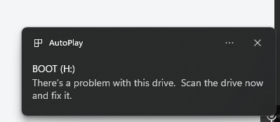
The Card will now show up as "BOOT".
Open the system.cfg file.
it never showed up a drive I could use.
oh what the fffff
Sure, windows does not support ext4 partions
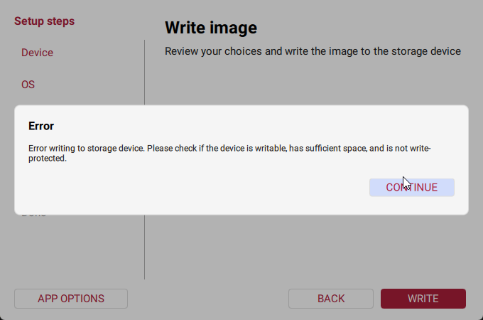
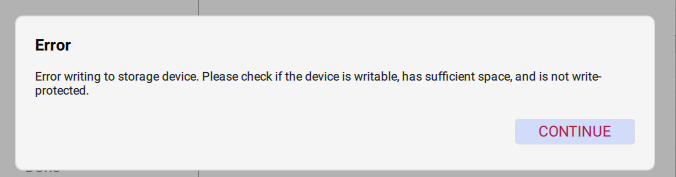
used balena this time instead, told me there was a "problem with boot" and it told me i had to format it
That was likely because it did not like the ext4 and or connect or disconnect with windows.
Well how am I supposed to set the wifi information...I was able to do this prreviously for a different printer
Pi flasher does not work for no images.
and the printer doesnt have an SFP port sadly
Long Ethernet cable
dont have any :/
sadge
guess i might have to hook up the screen early.
I am terrifed to turn this thing on lmao
@sweet jasper yo
Concerned about your wiring? Post a few pics please
I took a whole ass video but it's too spicy for discord 🙄 why do I pay for nitro


I have the power to the SSR unhooked from the distribution board
Looks pretty good. I hate that these two wires look similar

Wdym?

Just that the colors look similar at a casual glance. If you want cream of the crop review, post in #voron_electronics and ask them for a sanity check
from my lookovers, + is connected to + and - is connected to -...
I would be cool with plugging it in. Just be ready to reverse that decision.
At some point, you have to have faith in yourself.

did you flash the board and the OS?
(the 2 sd cards)
you didn't flash the boards sd card then yet?
Is that the 128 gig one..?
the 128mb one? yeah
I kinda need to get the os working before I can flash this one tho
Which needs to be built on the os
you do both the board SD card and the OS sd card at your personal computer though...
you still need to flash klipper on the board after that.
and then flash klipper on the toolhead board
didnt realize i had to flash the 128 on my pc
but also katapult (before klipper) on both of them
(or whatever its currently called)
Which guide is this in..?
im looking at the bttwiki guide and the formbot 2.4 r2 guide, neither of them mention this
eeeeuuuuuuhhhhh.... guides....uhhh... its a little broken up i'll post what i got here.
let me see if its on page 958 of the voron manual
nope
not one mention of firmware in the voron manual
wait.... is the SD card on the m8p the sd card that holds the klipper/katapult flash??....
i literally have no idea
that was for the other observers
https://www.youtube.com/watch?v=7x-eafpESLc&t=1297s this guy downloaded the file straight from armbian instead of the one from github like i was directed to
For CANbus please follow esoterical’s a guide over mine: https://canbus.esoterical.online/
Turn your dream 3D Printing project into a reality at PCBWay:
https://pcbway.com/g/s49dwT
Hope you guys stick it out for this long video. Thanks again to Formbot for hooking me up with a discount. I really like this kit and if you want to build a Vo...
download this PDF
https://github.com/bigtreetech/Manta-M8P/blob/master/V2.0/BIGTREETECH MANTA M8P V2.0 User Manual.pdf

GitHub
Contribute to bigtreetech/Manta-M8P development by creating an account on GitHub.
mhm
so they lead you to here right https://github.com/bigtreetech/CB1/releases
I downloaded the file and flashed it, but the file they edit (ON WINDOWS) is in a "BOOT" partition that its supposed to create (page 29)
GitHub
OS System image for CB1. Contribute to bigtreetech/CB1 development by creating an account on GitHub.
their file is called raspios-bullseye, but the latest file is for debian 12 for the cb1.
you just open the SD card on windows?
hmmm.... windows 11 or 10?
normal
oh sure..THIS time it opens...
let me see win+E
it was telling me to f ormat it before
progress boys
the manta has 2 sd card slots, i assume i plug it into the top one under the cb1
i think the one for the CB1 is under the cb1, lemmie check.
i dont think either slot is mentioned in the manual
its listed just not marked in the diagram
you set the wifi password and stuff?
yup
did you plug in the wifi antenna?
ah

the small SD card goes on the end
the RPI sd card goes on the side
the only reason i probably figured this out the first time, is because i broke my m8p mounting bracket.
the small one is the MCU one, on the silkscreen.
CARD is for the CB1
the Rpi one is the one that says card

looks right to me
Ok
was it in the wrong one before?
ah.
but no antenna
if you have an ethernet cord, thats also an option
it will eventually, but its in the other room and i dont have one long enough
we arent even to canbus yet
i would try to find the tiny string antenna that should have come with the cb1
this is confusing lmao theres like 2 sd cards, but 3 boards need to be flashed..
I plugged it in
I think I found the ip for it but ssh is refusing my connection lmao
grrrr
keep in mind that, i think the CB1 will only connect to 2.4ghz wifi, not 5ghz, unless it has a dual wifi mode
kk
do I really gotta enable root ssh on the sd before plugging it in
you used the RPI image from the git right?
GitHub
OS System image for CB1. Contribute to bigtreetech/CB1 development by creating an account on GitHub.
its not taking username: biqu password: biqu
?

its not even asking for a password
i guess its possible this isnt even it..
but..lmao
if only i had a long enough ethernet cable.
bruh
the wifi lines were commented out
im gonna lose my shit
#-----------------------------------------#
check_interval=5        # Cycle to detect whether wifi is connected, time 5s

eth=end0        # Ethernet card device number
wlan=wlan0      # Wireless NIC device number

hostname="BIGTREETECH-CB1"

###########################################
# System time zone setting, default Time zone: Etc/UTC (UTC, +0000)
# More settable time zones can be viewed by running the command: timedatectl list-timezones
#TimeZone="Asia/Shanghai"

###########################################
## klipperScreen Target Screen
## ks_src: "HDMI-1", "TFT35"
#ks_src="HDMI-1"

## ks_angle: Rotation angle
##       normal: 0; inverted: 180;
##       left: 90; right: 270;
#ks_angle="normal"

###########################################
## wifi name
WIFI_SSID="Virus.exe"
## wifi password
WIFI_PASSWD="NkYwAbLHjp3yW&"

###########################################
# BTT-PAD7 (ON/OFF)
BTT_PAD7="OFF"
# touch vibration effects
TOUCH_VIBRATION="OFF"
# touch sound effects
TOUCH_SOUND="OFF"
# Automatic brightness adjustment
AUTO_BRIGHTNESS="OFF"
###########################################
idc if u know my wifi creds, come find me lmao
Do you see stuff on the LCD?
nope, just a backlight
do you have the HDMI-5 or something
it says btt hdmi 1.2

GitHub
This library contains all the open source materials of BIGTREETECH touch screen hardware. - bigtreetech/BIGTREETECH-TouchScreenHardware
Which port is it plugged into?
probably need to tweak the config file to get it to recognize the screen
Did you power cycle after moving?
yes

do i need to like...hold anything while its booting..??
no
is the wifi antenna extremely short range or something?
can i use a wifi dongle?
I would expect something to be showing up on the screen
This seems like the Pi instructions not the CB1.
do me a favor and run angryip so that we know we know we have the right IP
ngl, i dont think its connecting. period.
its not getting a lease, its hostname is set to hostname="BIGTREETECH-CB1" and i dont have a device called that connected
i could have swore these were the instructions i used for the CB1
PI OS would not be used for CB1.
seems like some people have issues connecting via wifi for the first time
personally, i also used an ethernet cable during setup
Move the printer?
The Dr that repaired my hernia yesterday would say no
Fair enouh.
there is a green flashing light next to the cb1..
You attached the antenna right?
Is there a light under the heat sink you can see?
i do have a usb wifi dongle i could try..
And there's no output to the display?
fair. can you show the Dip switches near the cb1?
Likely the pi isn't booting, try pressing down on the top left corner of the cb1
The corner towards the middle of the board
Uhhhh
The mounting on mine had issues and would disconnect randomly
The things covered in yellow?

Nothing
There should be four in a row
Likely covered with orange
This green light keeps flashing

I think that's the one that means the pi is alive
Not sure why it wouldn't show on the display though...


That's for the microcontroller
Oh
What's this switch?

Should I try the USB wifi dongle?
I'd have to change a setting in the file right?
Do you have a computer next to the printer?
I'm gonna re flash
I have a laptop I could pull out.
Can you just run Ethernet to the computer
I guess try that and see what happens
Don't forget to reconfigure wifi when you do
ok
Mother ffffff

https://i.imgur.com/hxbaGZQ.png back to this crap
i wonder if my sd card is bad.
is your wifi name really virus.exe ?
yes
for my 2.4
my 5ghz is called virus.msi
2.4 is my IOT network also, sergregated vlan
was checking to see if periods in the wifi ssid need to be escaped. they dont.
im getting the same error on a completely different computer so either the iso is fked or my sd card is.
or...the reader i guess?
its certainly possible that the sd card is bad
of course i dont have another one
if i were to get a new one from best buy tomorrow... is there any specific kind i need?
A 32 gig micro SD is $42 rn??
Yeah all the silicon is getting expensive
Production is being moved to ram from storage iirc
It's just worstbuy pricing, Amazon is still fine
Nevermind then
Did you try Ethernet yet?
Or the lite iso
Ethernet from your laptop to the printer should work
I think
For ssh? Or..
For ssh
What would I even use for an IP.
i would try a sandisk or samsung 32gb from bestbuy.
but yes, he wants you to try to log into the pi directly from PC to pi with ssh.
Ssh requires a hostname/ip to connect to though
might be able to find the ip with angryip
Hmm..
Not entirely sure, if you're on Windows I think you can just find the connection info somewhere since you're only connected to one device
Just in the Ethernet settings
I haven't done it before but you should be able to connect
ah. i found the setup guide i used
Not a fuckin thing.
GitHub
OS System image for CB1. Contribute to bigtreetech/CB1 development by creating an account on GitHub.
Didn't think this would be the hard part.
i did
Did you try the lite version maybe?
Minimal. Whatever it's called
The one that doesn't have whatever crap btt decided was needed
Honestly at this point I'd recommend adding a cm4 or pi4 to your Amazon order
In my experience the cb1 sucked
Well that image actually successfully flashed with pi imager but still no image on screen

Armbian
Download Armbian for BigTreeTech CB1 by Bigtreetech. Standard support, 9 images available including Noble, Trixie, Resolute, Forky, Sid.
Oh I didn't even know that was there
I just grabbed the minimal one from btt's GitHub, that version is probably cleaner though
Does it show up on the network?
And the green light is still blinking right?
no, yes