#Picked up a used 2.4 - Need help with config
54 messages · Page 1 of 1 (latest)
(I'm hoping you're talking about potato being some kind of nickname for that board and not the debian release, which is is 22 years past end-of-life... 🙃 )
Then there's probably some figuring out to do with regards to how things are wired. You'll need to look into the electronics bay and answer at least these questions:
- What kind of Octopus is it (1.0, 1.1, Pro 1.0 or Pro 1.1)
- Do you have a toolhead board? Is it a "simple adapter" one (like a HartK board) or something "smart" connected via CAN or USB (like a BTT EBB SB2209, or an LDO Nitehawk)? If it's CAN, does it have a separate adapter (like a U2C) or using the Octopus as a canbus bridge?
- Run
lsusbandls /dev/serial/by-id/, it will tell you something about what's there too. - What stepper drivers do you have? Most kits have TCM2209 allover, but especially the AB motors are often changed for something else (TCM5160 or 2240 or who knows). You can usually see on the edge of the little step stick board, or checking the tiny writing on the driver chip on the underside of one. If it's BTT ones, you can usually tell if it's a 2209 or not by the size/color of the heatsink.
- What stepper driver slots are used for what motor? The usual deal is to just use the first six/seven stepper slots for B, A, Z, Z1, Z2, Z3,E (last one depending on if you have a "smart" toolhead board or not). The fourth stepper motor should hopefully be unused, as that is just a parallel connector to the third one (for printers with dual z steppers on one channel, which this voron is not). And even more hopefully the motor wires are labelled...
- Check where all the other important things are connected (bed and hotend heaters and thermistors, X/Y endstops and tap).
- Check that the wiring generally isn't too insane.
- Take plenty of pictures, it can help a lot both now and later.
You should probably do this following along with the electronics section of the Voron assembly manual, to see how close this is to a "stock vanilla" build. There's a lot of variation in how electronics can be set up, but if it's close to a standard LDO kit it should make things a bit easier.
For a klipper config, I think the Voron example config is one of the best starting points:
https://github.com/VoronDesign/Voron-2/blob/Voron2.4/firmware/klipper_configurations/Octopus/Voron2_Octopus_Config.cfg
It still has to be adapted for the specifics of your build (the TAP and possible toolhead board). Voron owners who never invest the time to go through and understand how the config actually works usually have a hard time, so that is worth doing. I personally always remove the various "leftover bits" (for other size printers or something) instead of leaving them commented out just to keep things a bit more compact and readable.
I have the base config setup now and when i load mainsail i can see the printer and adjust the temps ont he bed / extruder. I cannot however home it. When i home it just crashes into the bed 🙁

Then it's probably a good idea to go through the "startup procedure" here:
https://docs.vorondesign.com/build/startup/
Just to verify things are connected where they should (and the config matches the hardware/wiring), and that motors are turning in the right direction.
if i goto the tool head and manually lift the tool head, the LED for the tap, changes to red. implying thats working. But something in the config is not
That LED does indicate that the tap has power and that it "mechanically works", but it doesn't tell you where it's been wired in.
And the fact that you can read extruder heat probably means you either figured out already how the toolhead is wired. Many LDO kits shipped with a HartK toolhead board (which is just a breakout board to wire everything into the octopus), that should make things a bit easier.
i did find the breakout board that everythign is connected to
but my question is, what in the config do i change to make the homing work lol
Which one is it?

You need to check that the endstops are set up right, assuming you even have them for XY. Usually microswitches on the gantry, possibly one mounted on the side of the toolhead. Then verify that they are wired/configured right, either by a QUERY_ENDSTOPS or in the Endstops section on the Machine page.
If you don't have endstop switches (or maybe those little hall effect sensors, not sure if those came in any LDO kits), you'll have to get familiar with sensorless homing...
I ran the query and stepper_x:open stepper_y:open stepper_z:TRIGGERED
the z shows triggered, even if i move the tool head up or down
That looks like the "downstairs end" of a HartK toolhead board (LDO-branded, which is what they had in a lot of their kits). Also looks like regular BTT TMC2209 stepper drivers all around.
x and y function just fine via query. as i move the tool head, they are opening / triggering .. its just z
That probably just means it's not wired to the endstop port you have configured. Endstop switches are usually wired to be "normally closed", so if the switch is disconnected (or some wire breaks) they will read "triggered" to prevent you from crashing things.
Also could you post the config file (printer.cfg) as it looks so far, or maybe even a klippy.log file?
#####################################################################
Z Stepper Settings
#####################################################################
Z0 Stepper - Front Left
Connected to MOTOR_2
Endstop connected to DIAG_2
[stepper_z]
step_pin: PF11
dir_pin: !PG3
enable_pin: !PG5
rotation_distance: 40
gear_ratio: 80:16
microsteps: 32
endstop_pin: PG10
#endstop_pin: probe:z_virtual_endstop
Z-position of nozzle (in mm) to z-endstop trigger point relative to print surface (Z0)
(+) value = endstop above Z0, (-) value = endstop below
Increasing position_endstop brings nozzle closer to the bed
After you run Z_ENDSTOP_CALIBRATE, position_endstop will be stored at the very end of your config
#position_endstop: -0.5
##--------------------------------------------------------------------
That's good, that's two out of three!
@fair pivot When posting configs or logs, please surround with code fences (```) so that Discord formats them correctly. Example:
```ini
[mcu]
serial: /dev/serial/by-id/usb-klipper-12345-if00
```
[mcu]
serial: /dev/serial/by-id/usb-klipper-12345-if00
#   Z Stepper Settings
#####################################################################

## Z0 Stepper - Front Left
##  Connected to MOTOR_2
##  Endstop connected to DIAG_2
[stepper_z]
step_pin: PF11
dir_pin: !PG3
enable_pin: !PG5
rotation_distance: 40
gear_ratio: 80:16
microsteps: 32
endstop_pin: PG10
#endstop_pin: probe:z_virtual_endstop
##  Z-position of nozzle (in mm) to z-endstop trigger point relative to print surface (Z0)
##  (+) value = endstop above Z0, (-) value = endstop below
##  Increasing position_endstop brings nozzle closer to the bed
##  After you run Z_ENDSTOP_CALIBRATE, position_endstop will be stored at the very end of your config
position_endstop: -0.5
##--------------------------------------------------------------------

##  Uncomment below for 250mm build
#position_max: 210

##  Uncomment below for 300mm build
#position_max: 260

##  Uncomment below for 350mm build
position_max: 310

##--------------------------------------------------------------------
position_min: -5
homing_speed: 8
second_homing_speed: 3
homing_retract_dist: 3
i assume its that section thats giving me the hard time
So, the endstop pin configured there, PG10 is the third endstop connector on the octopus. You need to check if that's where the tap is connected (I'm guessing the first two, which are PG6 and PG9 are used for X and Y). It could be connected to any of the other endstop ports, or the PROBE port (which is near the lower-left corner of the octopus).
Should be a wire from the toolhead board, probably labelled XES or PROBE, to either of those places.


That may be a step for later, but I think you need to have the endstop_pin for Z be that probe:z_virtual_endstop option and define the endstop pin in a [probe] section. I think it's needed for QGL to work, and with a tap you usually want some hotend temperature control logic there too (to make sure the nozzle isn't so hot it will make marks on the bed. But for just figuring out the wiring and pin used, you don't need to just yet.
I see no z end stop
Right. If I remember correctly, those XES and YES wires do not actually go to the toolhead. It's basically just a "second function" to bring two two-pin connectors together to that four-pin one (XY STOP), which then usually goes to a little endstop board mounted under the right-side XY joint on the gantry.
makes sense
i made the virtual end stop change but i dont understand the probe reference
#   Probe
#####################################################################

##  Inductive Probe
##  This probe is not used for Z height, only Quad Gantry Leveling
[probe]

#--------------------------------------------------------------------

## Select the probe port by type:
## For the PROBE port. Will not work with Diode. May need pull-up resistor from signal to 24V.
#pin: ~!PB7
## For the DIAG_7 port. NEEDS BAT85 DIODE! Change to !PG15 if probe is NO.
#pin: PG15
## For Octopus Pro PROBE port; NPN and PNP proximity switch types can be set by jumper
pin: ~!PC5

#--------------------------------------------------------------------

x_offset: 0
y_offset: 0
z_offset: 5
speed: 10.0
samples: 3
samples_result: median
sample_retract_dist: 3.0
samples_tolerance: 0.006
samples_tolerance_retries: 3
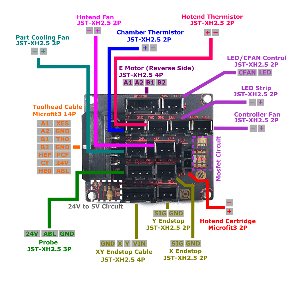
That breakout board should be this one:
https://docs.ldomotors.com/toolhead_wiring_kit/breakout_pcb_pinout.png
(found on https://docs.ldomotors.com/en/voron/toolhead_harness)
It's likely the Z TAP is wired to the "PROBE" port there, and then maybe going to the probe port on the octopus.
That is a good start for a probe section. The comments refer to the inductive probe that often comes with the kit. If you can find a wire going to the probe port, pin: ~!PB7 is a good starting point (though you may need to remove the ! if it's acting inverted).
There are a couple different ways to sort out the power for a TAP probe (as the probe port by default provides 24V), but I'm assuming whoever built this did that already and that there should just be an adequate signal somewhere.
so question.. I just moved the gantry manually to the center
i homed, and X went to the wrong side to home.
#   X/Y Stepper Settings
#####################################################################

##  B Stepper - Left
##  Connected to MOTOR_0
##  Endstop connected to DIAG_0
[stepper_x]
step_pin: PF13
dir_pin: !PF12
enable_pin: !PF14
rotation_distance: 40
microsteps: 32
full_steps_per_rotation:200  #set to 400 for 0.9 degree stepper
endstop_pin: PG6
position_min: 0
##--------------------------------------------------------------------

##  Uncomment below for 250mm build
#position_endstop: 250
#position_max: 250

##  Uncomment for 300mm build
#position_endstop: 300
#position_max: 300

##  Uncomment for 350mm build
position_endstop: 350
position_max: 350```


are you saying the ! will fix that part?OK, so X/Y direction is a different set of things to check separate from the Z probe. Best thing to do there is to follow the Voron setup guide I linked earlier, it tells you what to do if the toolhead is moving in the wrong direction.
You don't need to do full-on homing, you can just position the toolhead in the center, and do a G92 X150 Y150 and then move the motors with the web ui buttons (I think). Or use FORCE_MOVE (https://www.klipper3d.org/G-Codes.html#force_move)
TL;DR: Put [force_move] somewhere in your config to enable the feature, then use something like SET_KINEMATIC_POSITION X=150 Y=150 Z=20 to make the printer think it's homed and good. Then move the toolhead a little bit in X and Y to see it does the right thing.
Also a good idea to move a bit in Z (though not so much it might crash the toolhead into the bed), to make sure all the Z steppers are going in the right direction.
I've got X and Y going the right direction and homing
i have z going in the right direction
i.e. if i manualy move it all to center, query shows all open. If i move them to the proper places, query shows triggered.
so 1 step closer
Good stuff.
Now for that tap, you need to figure out where it's connected. It's not 100% certain that it's even going via that breakout board (where it could be using pretty much any leftover connector), it could also be a separate cable going all the way out to the toolhead.
BTW just as an example, this is what my [probe] section looks like, also using a tap (it's with a nitehawk sb toolhead board so a different pin, but the rest should be applicable):
pin: !nhk:gpio12 #Y endstop pin on Nitehawk used for TAP
x_offset: 0
y_offset: 0
#z_offset: 0

speed: 10.0
samples: 2
samples_result: median
sample_retract_dist: 3.0
samples_tolerance: 0.02
samples_tolerance_retries: 3

activate_gcode:
    {% set PROBE_TEMP = 150 %}
    {% set MAX_TEMP = PROBE_TEMP + 5 %}
    {% set ACTUAL_TEMP = printer.extruder.temperature %}
    {% set TARGET_TEMP = printer.extruder.target %}

    # Check if extruder target is too hot
    {% if TARGET_TEMP > PROBE_TEMP %}
        { action_respond_info('Extruder target of %.1f°C is too high, lowering to %.1f°C' % (TARGET_TEMP, PROBE_TEMP)) }
        M104 S{ PROBE_TEMP }
    {% endif %}

    # Nozzle may still be too hot
    {% if ACTUAL_TEMP > MAX_TEMP %}
        { action_respond_info('Extruder temperature %.1f°C is too high, waiting until below %.1f°C' % (ACTUAL_TEMP, MAX_TEMP)) }
        M106 S255 #Run parts cooling fan to cool quicker
        TEMPERATURE_WAIT SENSOR=extruder MAXIMUM={ MAX_TEMP }
        M107
{% endif %}```(deal with this AFTER you have the probe triggering correctly, until then it's useless)
But it has some gcode in there to make sure the hotend isn't above 150°C before doing any probing.
You should have a z_offset in there to start, it's just that when you tweak that in mainsail, it will comment that out and put it's own one in a special section at the end of the file.
Buying a used Voron is always a bit of a gamble. Not only are you missing out on the hours of fun of building one, but there is also a lot of variety in what parts are in it and how they're connected (even if you have a well-known kit and follow all the instructions, there is still some things one can do differently). And all of that just has to be figured out.