#Bradford White GEA2
1 messages · Page 1 of 1 (latest)
 wheat abyss
I got one of these https://amzn.to/3yQVAWT and measure the voltages (I don’t have an oscilloscope or signal analyzer)
From left to right on the terminals I numbered them as 1 to 8

Between 1 and 3 there was ~ 7.22v
Between 1 and 7 the voltage seemed to bounce between ~9 and 12v
Between 1 and 8 there was a constant ~12.2v
This is with the heater (heat pump) running
8 seems to be ground
7 seems to oscillate between voltages
Terminals 3 and 7 bounce between 3 and 5v
Terminals 3 and 8 is a steady 5v
The rj45 terminal block is wired 568b per the description
 fallen chasm
Nice, that seems to match what I'm seeing; I have a very basic Python script setup to send a single broadcast packet via an inverted Arduino software serial interface. I think I should have some time tomorrow. Hopefully I can get a response on one of the 0V pins.
For reference, this is what I measured (rounded to whole volt):
pin 1: GND
pin 2: 0V
pin 3: -7V
pin 4: 0V
pin 5: 0V
pin 6: 0V
pin 7: -12V
pin 8: -12V
Could be we have some differences, as I see in the bottom-left of my control panel 238-52365-00, whereas yours is 238-54366-00....
You may have a newer revision
wheat abyss
I don’t think the connect device has changed so I doubt the communication between them has either.
fallen chasm
I'm not sure I follow your measurements; you say you're measuring between pins 1 and X, but then say pin 8 is ground?
wheat abyss
Measuring with negative on pin 8 and positive on Pin 1, I get 12v.
1 is likely ground I don't know why I thought 8 was
for pin 7, it definitely jumped between 9 and 12 volts
pin 3 was 5 volts
and when measuring between 3 and 7 it jumped between 3 and 5v
will try and take a look in the connect later today or tomorrow.
fallen chasm
I ordered the same terminal you have. Mine should be here tomorrow, so I can stop using my ghetto cable haha

I do wonder if you're on to something, I'm seeing -12V and -7V when I test with GND as pin 1. I wonder if I'm looking at it backwards. The photo of the board I shared earlier shows that it should be +5V (and presumably +12.3V), so what I'm seeing with the scope doesn't really make sense
fallen chasm
Hm, I may have to wait to see what you find probing your wifi module. I've sent a broadcast packet over all 0V lines and haven't received a single response. Kinda stumped myself.
Packet looks like:
E2 FF 08 BB 01 9A 85 E3
E2 packet start
FF packet dest (broadcast)
08 packet length (bytes)
BB packet source/sender
01 read firmware version
9A CRC MSB
85 CRC LSB
E3 packet end
Okay, good news! Pretty sure I figured out there the data pin is. I think you were right, pin 8 is ground, but pin 7 seems to be acting as the data pin for me. I'm getting a response!
Weird part though... the water heater is only signaling at 1V... Not sure what the deal is with that. Any thoughts @vague ravine ? It looks like a valid GEA2 packet, just... 1V for some reason, haha.
The 3 screenshots I sent are, in order:
- The packet sent by my Arduino
- Both packets
- The response from the water heater
Arduino packet:
E2 FF 08 BB 01 9A 85 E3
Water heater response packet:
E2 BB 0C 60 01 04 09 04 16 CB A0 E3


I can see the packet on the scope, but of course the Arduino isn't seeing it b/c the voltage is so low
Note: I rescaled the voltage to 330mV per division in the 3rd screenshot
 vague ravine
Can you double check the ground connection against chassis ground? Maybe it's just a lower voltage and the 1V is relative to it, not ground?
fallen chasm
vague ravine
Can you double check the ground connection against chassis ground? Maybe it's ju...
Hm, I think it must be isolated.
All 8 pins read 3-4 MΩ to chassis ground
I may have to take the top housing apart again so I can expose the control board I shared the picture of before. That way at least I can be sure I'm on GND
 fallen chasm
That being said, I'm relatively confident I've identified GND. With GND as pin 8, I'm getting a clean 5V and 12.2V to pins 3 and 1 respectively.
I'm also only able to get any response from pin 7 with pin 8 as GND, only at 1V
fallen chasm
So I shut off the breaker, opened the control panel, and did some continuity testing with my multimeter. I can confirm 100% that:
pin8: GND
pin3: 5V
pin1: 12.3V
However, pins 2, 4, 5, 6, and 7 don't appear to be connected to anything I was able to probe from the back PCB (and I spent a good hour or more looking). I would have thought they'd be connected right in the same place as the 3 pins I mentioned above, but that doesn't seem to be the case.
fallen chasm
Is GEA1 also 5V? Everything in the docs on this heater says it should be GEA2, but kind of grasping at straws at this point, haha
wheat abyss
I haven't had time yet to pull down my bwconnect box (it's mounted to the ceiling above the water heater) to open it and probe voltages inside it yet. still on my todo list - I started to do it last night but crashed after getting less than 4 hours sleep the night before. 😬 .. stuck in office until later today.
fallen chasm
No worries, definitely more of a weekend project, hehe
fallen chasm
Well, I may not be getting 5V back from the board, but I sure can write to it!
https://services.pyrahex.com/public/videos/tmp/water_heater.mp4
This document seems to be pretty accurate for the Bradford White as well:
https://github.com/doitaljosh/geabus-documentation/blob/master/hewh-interface.docx
Everything I tried responded as expected, even though I had to use the scope to see it lol
Apparently you can get pretty wild and directly control the compressor, heating elements, etc. I think I'll stay away from that though, haha
wheat abyss
wow. have you seen this? > https://github.com/mulcmu/esphome-ge-laundry-uart would be cool to get this into an esphome component
fallen chasm
The document makes it sound like you can even set the temperature above the normal lockout, to where it will actually make it hit the thermal cutout
huh, I haven't seen that. I'll check it out
wheat abyss
So does it seem like BW uses same commands etc as the GE? that doc is a map to everything if so. for me most important is mode and temp control, and energy monitoring.
fallen chasm
Yep, seems to be that way. I'll probably hold off on working on it too much more until I can figure out why I'm only getting 1V back from the water heater. I'll be interested to hear what level the BWCAdapter is running at when you have a chance to check that out.
If It should only be 1V, I need to get a logic level convertor or something to avoid overdriving that pin. Also to actually receive responses without having to use my scope, haha
wheat abyss
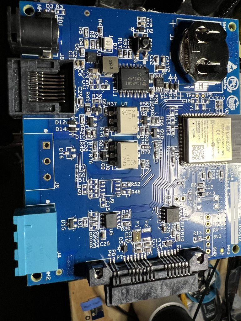
I did not do much probing but this thing has test points every where . Pics from multiple angles for best light to see traces. Posted in Imgur so not as bad compression https://imgur.com/a/qM5SQTD
 vague ravine
Interesting, it has two optoisolators like the other Beans
And a straight up ESP32 module 😄
fallen chasm
Nice. I'd definitely be interested what pins it's using to talk to the water heater, and at what voltage they're talking
fallen chasm
It's interesting that they have pins 1, 2, 7, 8 circled on the back. If it matches up to what I've measured:
1: 12V
2: unknown
7: DATA
8: GND
Not sure what pin 2 is for, I couldn't get any communication on it, and it isn't carrying any voltage like pins 1 and 3
fallen chasm
Of course, that's assuming they are numbering in order with the RJ45 connector, haha
wheat abyss
I’ll check that.
The connect box is powered by 5v in the little bit of probing I did I don’t think I saw anything over 5
wheat abyss
1,2 & 7,8 match our original numbering: #1279229546608066611 message
fallen chasm
I think 5V is on pin 3 though
wheat abyss
the whole pin order matches.
there was one test point that had alternating voltage. i'm trying to trace it now.
majority ot TPs were 3.3v

 fallen chasm
Interesting that pin 7 seems to connect through C29 to GND on that optocoupler
https://rocelec.widen.net/view/pdf/rwjc9al1ln/ONSM-S-A0003590761-1.pdf?t.download=true&u=5oefqw
wheat abyss
pin 8 does too.

as far as I can tell 3,7,8 are the only pins passed through to the board
fallen chasm
My brain doesn't do so hot with circuits, but it seems odd that pin 7 and 8 are set up that way.
Looks like maybe pin 7 is controlling current flow from pin 3 via that (transistor?) before R41?
Not sure I know what I'm looking at tbh, haha
wheat abyss
yeah this is a little over my head as well. a bit more going out from the optocoupler pins... hurts my head.
 fallen chasm
You know, we have all these lovely 1-wire protocols out there... why can't they use something normal, haha
wheat abyss
I'm getting some of the boards from this project made. #1279229546608066611 message
they say it supports gea2 so figure what the heck.
fallen chasm
It does look like the water heater side is tied into the emitter side of the top optocoupler, and the detector side of the bottom one. Makes sense they set it up that way to split up send/receive.
No clue what all the crap to the left of that is doing, haha
fallen chasm
wheat abyss
they say it supports gea2 so figure what the heck.
Can't hurt to try
 fallen chasm
I think GEA2 can be full-duplex, but it sure doesn't look like this water heater is
Ah yeah, it says there
7 is halfdplx, 4&5 are fulldplx tx/rx
Damn, that document is excellent actually
Interesting, I wonder if I can get what I need with just a cap and 2 diodes...
wheat abyss
I should have the boards in a 10 days or so, they sent me questions including a photo so pretty sure they are done production , I didn't get fast shipping though, and have to get a few components still.
I think I'll have 5 in total so will be happy to send one.
the ge dryer is half duplex and this was the guys test setup. https://github.com/mulcmu/esphome-ge-laundry-uart/blob/main/dryer testing.jpg

buck converter, resister and one of these - https://www.dfrobot.com/product-2285.html
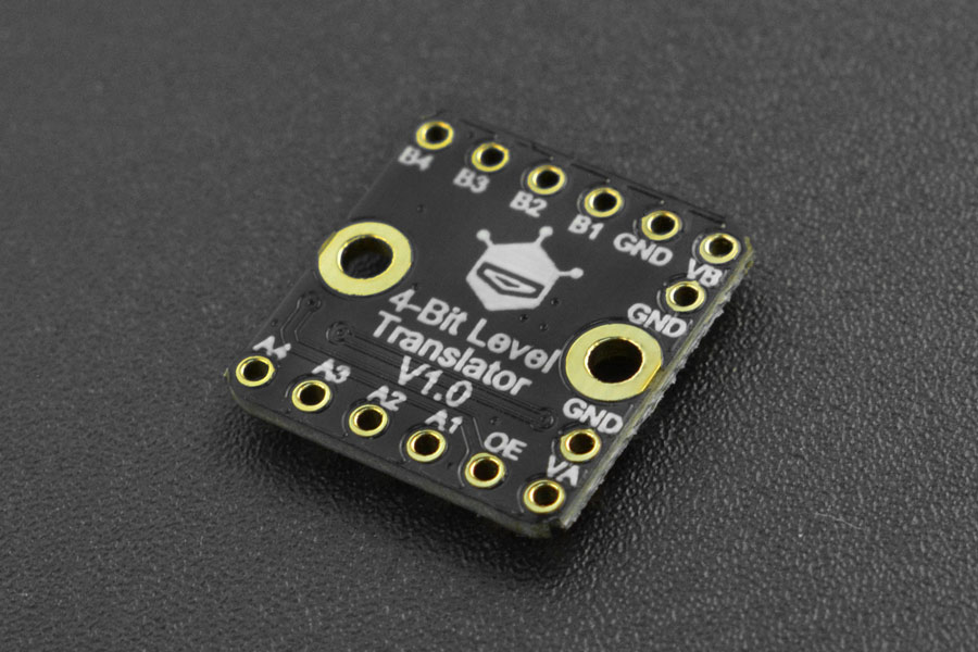
This 4-bit non-inverting translator uses two separate configurable power-supply rails.
fallen chasm
wheat abyss
I think I'll have 5 in total so will be happy to send one.
I appreciate the offer! I'd like to keep digging to understand all this a bit better though
fallen chasm
wheat abyss
the ge dryer is half duplex and this was the guys test setup. <https://github.co...
Hm, that looks about like what I'm doing with the Arduino, although I don't have the logic level converter since both (should be) talking at 5V
fallen chasm
I'm just stuck on why I'm only getting 1V from the water heater. Looking at all these example builds, I'm not seeing what is pulling that signal level up to 5V. Unless something is damaged on my water heater board? Kind of at a loss
fallen chasm
I went ahead and ordered a few logic level converters from Adafruit, I should be able to try that out this weekend. If for whatever reason the water heater is still talking at 1V (maybe something on the Arduino is pulling it low for some reason?), maybe I can at least use the converter to talk to it at 1V (it's only rated down to 1.2V, but I'm grasping at straws, haha)
vague ravine
Does the bus read 1.2V even when the Arduino is disconnected?
fallen chasm
I haven't tried that yet. I could probably test that with a simple voltage divider.
My plan was to try using the converter with Pi 3.3V -> water heater 5V. Using it more as a way to try to isolate whatever the arduino/pi is doing with pull-up/pull-down.
If I still see the water heater talking back at 1V, then I'll try dialing down that side to talk at 1.2V and see if that gets me by
fallen chasm
vague ravine
Does the bus read 1.2V even when the Arduino is disconnected?
Oh, I may have slightly misread your question. The bus never shows any traffic unless I poke it with a valid GEA2 packet first
When I send a valid packet using the Arduino at 5V, I get a response back at almost exactly 1.0V
vague ravine
What if you interact with the water heater via its buttons or knobs or something?
With my washer at least, every button and knob triggered a message
fallen chasm
I didn't see anything when I was testing before, but maybe that was before I was using the scope. Lemme give that a try
fallen chasm
Nope, I poked every button on there, but no GEA messages. Not sure if it's an external vs internal bus thing? I'm hooked up to the external bus on the RJ45 connector.
I did look a little closer at the responses to the Arduino's messages, and they're actually more like 0.8V
 vague ravine
Hmmm. What about if you power cycle the heater?
0.8V and 1.2V are really odd signaling voltages
fallen chasm
I can try that. 1.2V is the minimum rated voltage on the logic level converter I ordered, I'm not seeing that on the water heater
That's why I ordered the logic level converter too: to see if adding some isolation between the Arduino and water heater might show a different result. Like, maybe something on the Arduino is pulling that voltage lower than it should be?
I'm using the SoftwareSerial library with inverse_logic set to True. Maybe the Arduino's pull-down is too strong? Just spit-balling
I could also use a much shorter cable and test the voltage. I think I've been testing with a 3m cable so I can have my laptop set on the counter.
vague ravine
From what I recall, the bus has a global 4.7K (or 47k?) pulldown and individual devices pull it up to signal
Looks like for mine it was 4.7K. If the bus is nominally 3.3V, you'd need a ~1K pulldown to drop it to 0.8V. With a 5V bus, it'd be 1.5K.
fallen chasm
Not really seeing anything different after the power cycle