#annies projects
1 messages · Page 2 of 1
 nova ingot
ok, so i wired a pot into my circuit, a 10k. i tried implimenting the pot control but like i said .01v difference
do i need a different pot?
with an led thrown in, i get a 4.72 high and a 2.5 low
 keen epoch
How are you doing it? You need a much smaller pot to limit current, like 100 ohms
keen epoch
nova ingot
i did not, but i kinda discovered it. i could get 2 with resistors. that means i...
If you are trying to indicate battery power, you can only do so much. Dont forget about the constant drain on your battery while using this circuit.
nova ingot

im trying to vary the power
i only get drastic changes with this. when the led is removed, i only get a .01v difference
and i dont get a full 5v with the led
nova ingot
keen epoch
How are you doing it? You need a much smaller pot to limit current, like 100 ohm...
so the smaller the pot, the more it can restrict at the low end, the larger, the less?
keen epoch
So with that circuit, you risk burning out the LED. Put a current limiting resistor on it, you are basically varying the brightness
and you cant exactly measure power with the way you have shown. You need a load, like a resistor.
nova ingot
i know.
keen epoch
Use 100 ohms as as load, use a smaller pot and you'll vary the power. BUT note your also forming a voltage divider, so you may not get the voltage you want out
You'll have to use more advanced circuits if you want to add current limting
nova ingot
this is the current wire up on my breadboard, reading at a steady 3.91v
 keen epoch
Wheres the center lead of your Pot? Is it just floating?
nova ingot
oh, remove the pot
measured straight from the lipo charge board, which outputs the battery
keen epoch
But that will only give you voltage. If the pot is all the way to the left or right (depending how you have it hooked up) that would explain the reading close to the battery voltage. Turn the pot half way and re-measure
nova ingot
with a resistored 3.2v led, 2.54v-3.36v, with a middle of 2.57v
without the led, 3.95v-3.95v, with a median of 3.95v
@keen epoch
keen epoch
That makes sense. Your measuring the LED voltage + the resistor voltage
This is Kirchhoff's voltage law in action.
The sum of all voltages in a loop must be 0
This is the last thing I'll leave you for the night 🙂
This is the circuit you have. LED1 is assumed to be a blue LED and is assumed to be 3.20V.
VR1 is your output, Any where along that node, you will measure that voltage. So you are measuring the voltage across R1 and LED 1. Assume that VR1 is set to 0%, or its a "short" meaning, no resistance.

I have to refresh my memory for this, and I may be a bit tired.
Edit, scratch all of that. I may have misread. Your voltage shouldnt be going down that much with a single LED. I may have to answer this in the morning but are you trying to pull current from the charger or the battery?
nova ingot
battery via the charger
im removing battery level indicator for now and focusing solely on the output. i want to go from the battery to the charge board, to the 5v booster, to the pot, to the barrel port, then down the ground and back to the board with a switch somewhere in there to shut off all power @keen epoch
keen epoch
So the battery is hooked up, on the charger, and you are powering from the battery with the charger not connected?
nova ingot
correct
keen epoch
your battery shouldnt be dropping that much with a 10mA LED 🤔
 keen epoch
tie your free leg of your pot to 5V or CN2
its basically acting like a 10k resistor (or what ever value you picked)
nova ingot
so tie both to 5v?
nova ingot
wait, ione to 3v and one to 5v works
kinda. i get a low of 3.95 and a high of510
i found out how to use 2 pots, just for fun 😛
cant figure out how to get it lower. resistors seem to do nothing
keen epoch
ok so you have your 3 legs, 1,2,3, with 2 being the wiper or center. Connect that to your 3rd or 1st leg. that "node" will be your output
 nova ingot
ok. i have 1 and 3 at 5v and 3v respectively and 2 heading to the barrel (or the multimeter in this case)
keen epoch
hold on, you have two different voltages going to the pot?
nova ingot
yes. im trying to get the voltage output to be at most 3v to 5v
keen epoch
Dont do it like that, you could end up feeding the 3V supply. You wont be able to limit the lower range too much, at atleast not with out a buck-boost conveter
converter
nova ingot
should i ut in a diode to prevent feedback?
keen epoch
Let me think. You could do a diode "or" circuit. But if you are trying to limit current, a pot isnt the best way to go. Its easy, yes but you'll also end up varying your voltage too.
 keen epoch
so, think pragmatically here: Will the user (or you) ever have to vary the voltage between 3V and 5V?
Ive never had to do that. From 5V? Yes. But I would use an external supply
nova ingot
then i should replace the potentiometer with a toggle switch like originally had it
keen epoch
also the 5V power will dominate anything because its greater.
keen epoch
nova ingot
then i should replace the potentiometer with a toggle switch like originally had...
yes
nova ingot
so we are back around to the level indicator
tried and true method at least
since i have a sticker with voltage on it, should i just remove the leds that tell you which voltage you are using?
cause i really like the idea of using leds for that.
keen epoch
You can still use the LEDs
nova ingot
then i need to figure out how to impliment them, because i cant
keen epoch
to indicate which voltage is selected?
nova ingot
yes
keen epoch
You would need a DPDT switch
nova ingot
i dont have one yet
keen epoch
then thats what you need 🙂
nova ingot
i was hoping not to need one as they are bigger
keen epoch
There is another way, but its more complex

Electrical Engineering Stack Exchange
I am building 3V3/5V source for my breadboard. The actual voltage will be selectable by the switch. I would like indication, which voltage is actually selected by lighting green LED for 5V and yell...
or use comparators
Or possible even a TL431 circuit
but silicon is cheaper than copper, remember that 😉
nova ingot
no to the complex. here is a question. i can throw both my control box and my battery pack into one enclosure (the big one with window) should i do that since it will show a variety of somple components?
 keen nacelle
For reasons of looking cool? Or something else?
nova ingot
- a kind of intro level diy that introduces basic soldering, components, and whatnot, 2) to give a box that has switches, pots, and battery all in one. just plug into your breadboard and run jumpers to and from
ive got the proto types on my desk and they work well
it allows you to use less space on your breadboard too. the toggle switches alone take up 5 points for just 3 pins
nova ingot
you know what, ill make it an option. either the control box, the bat pack, or the combo
here is the question though: A) which pots do i use B) should i put in a couple selector switches so you can choose which switch or pot to use for a specific output C) is there anything else i should add, and D) what are some simple projects i should include for after the box is assempled
keen epoch
whats the purpose of the pots?
nova ingot
whatever the person wants really
keen epoch
you can just have them go to terminals "A,B,C" or "1,2,3"
nova ingot
yes, but which pots?10k, 100k, other?
keen epoch
Ive found 2k or 5k pots work best
nova ingot
i can currently get 1k, 10k, or 100k
keen epoch
1K would be OK. I would do 1K and 10k
nova ingot
should i do one or the other, or both?
keen epoch
Up to you honestly 🙂 it doesnt matter too much. Ive found that you lose some upper range with the 10k though.
keen epoch
Good idea
nova ingot
ill alow them to select the battery capacity, and the pot type. then ill assemble the kit and ship it out
i also had an idea to replace the led power level indicator section with a volt meter
keen epoch
Good 🙂 Just be aware of project creep and loosing sight of your intentions
keen epoch
nova ingot
i also had an idea to replace the led power level indicator section with a volt ...
I thought of that too
nova ingot

Put a voltage meter anywhere with this very handy display. These are often used by RC hobbyists for keeping track of batteries but we thought it would be great on a breadboard or enclosure. ...
so i can offer that as an option too
keen epoch
also good
nova ingot
anything you think i should add?
keen epoch
-User selectable 3.3V/5V
-Lithium Battery w/Level indication
-Integrated Charger
-Small form factor
-User selectable pots with knobs
Did I get all that?
I think without making it too complex your OK. I mean, we can get as complex as you want to get and learn a whole bunch of stuff, but then we have project creep.
So I think you are good.
nova ingot
user selectable switches too
im thinking of having all the switches and pots go to the same 4 rotary switches so you can assign them to different outputs without having to rewire
keen epoch
Why not have them freely available? They might use a pot and switches
nova ingot
exactly. each pot or switch will go to each rotary switch. they can set all 4 to the liniar 10 k if they wished, or each switch to a different pot or switch
then if they decide to swap out a pot for a switch, they just turn the rotary switch and select the toggle. no nttd to pull wires
i got tired of wiring but this is cort of what i mean

i may have to ixnay that for now
may nees a dp4t
nova ingot
im making one other mod to my prototype.
instead of a bunch of wires leading off the box, a port for one of these should do https://www.adafruit.com/product/1675

These little cables are handy when programming or debugging a tiny board that uses 10-pin 1.27mm (0.05") pitch SWD programming connectors. We see these connectors often on ARM Cortex ...
nova ingot
should i put a diode on the outgoing power line
id like to ad a small display but that may be too complex. plus id be starting into my other idea of a custom 100 in one electronic lab
keen epoch
FYI I may not to get to the rest of your Q's tonight, I'll be away
nova ingot
thats fine. im gonna start designing what i can. ill need the comparator version of the indicator but that can wait
nova ingot
im afraid i dont know how to wire a dpdt
keen nacelle
Looks like there are two inputs and four outputs https://learningaboutelectronics.com/Articles/Double-pole-double-throw-switch-DPDT
This is an article explaining what a double pole double throw (DPDT) switch is
and how it is used in a circuit
so absent a datasheet that comes with the switch, I'd imagine setting up a breadboard with power to an LED going through the switch could figure out the connections nicely
or a multimeter with continuity but unless you've bought one since we did that resistor measuring thing, that's not an option for you
nova ingot
ok. i figured it.its 2 seperate switches that share a single actuator
nova ingot
i know its Christmas day so you can feel free to ignore this stuff for the day, im just posting thoughts anyways, helps me think. happy Yuletide
im thinking of this instead nof the boost and charge boards as seperate items. this also allows the user to incorporate arduino projects right into the set. i can cut slots in the top for connecting the other arduino boards, or even to connect displays and other boards as they become more advanced in electronics, all while keeping the ribbon cable outpute for everything. they can even use jumper wires to go right from the ribbon cable port to the arduino projects. they wont even need special knowledge to solder in the shield as the box will be primarily for the control hub. maybe ill sell 2 versions, one with arduino, one without, naybe even a rasberry version or something. right now, just the arduino and the non arduino. in the non arduino, ill replace the 2 boards with a bower boost 500c once they come in
keen epoch
FYI this popped up on reddit today
https://www.reddit.com/r/AskElectronics/comments/rovfch/battery_indicatornot_working/
nova ingot
I still need to set up the indicator. I have the arduino compatible board designed but without the indicator.
nova ingot
Ok. Im gonna go comparator route, but am a little lost on it
keen epoch
How so?
Do you know how comparators work?
If not, I would suggest delving into books 🙂 or YT
keen epoch
To understand them or to play with them?
keen epoch
They are called Comparators 🙂
you can technically use an op-amp in open loop mode but this..has its own set of isssues you want to avoid for now

Learn more about the TI Precision Labs - Op Amp Evaluation Module used in the hands-on lab modules
https://www.ti.com/tool/ti-plabs-amp-evm
The comparator’s job is to compare two analog input signals and produce a
digital or logic level output based on that comparison. In this video
we’ll discuss the basic functionality of the analog compara...
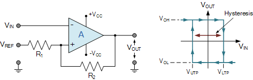
Electronics Tutorial about the Op-amp Comparator and the Op-amp Comparator Circuit used as a voltage comparator to switch between different voltage levels

The LM311 is designed to operate from a wide range of power-supply voltages, including ±15-V supplies for operational amplifiers and 5-V supplies.
OR LM339
which is a quad
nova ingot
i was just about to link that last one and ask if it would work.
so i would only get 4 leds, 5 if i wire the lowest one into a low battery output pin
keen epoch
Your 4th LED would technically be a low LED pin
Think about it: Do you really need a 5th?
You'll know via the charger the battery is charged.
Your 1st led would be your "4.20V" LED. 2nd would would be 4.2-3.8, 3.8-3.3, then 3.3V and lower would be the last LED.
nova ingot
id like one but no. ill have to modify my label nut it shouldnt be too hard to do
i could place the 5v led indicator as the 5th, then i wont have to change my main label. ill just have to remove the 3v indicator and reroute the 5v indicator. technically it would be mostly unlit, but it will look nicer with the 5th i think
keen epoch
You could have 5V,3.3V, Then below that Battery level: Charged, 3.8V, 3.3V,3V, 2.9V (low battery)
Before you do this, be sure to read up on how this will work. Try to examine the pitfalls of using certain components. If you dont have them, you can also simulate stuff online
keen epoch
Just checking in-How is your understanding with comparators going?
nova ingot
On hold for the short term
Hard couple of days
going to see about getting one this week
keen epoch
Alright. Hope everything is ok
nova ingot
just meh. not feeling like learning but wanting to build. no real excitement though
keen epoch
I get that. I really do. Just want to get your hands dirty or build a kit or something
and none of your current projects phase you.
Feelings this myself, which is why I made "shop time" to literally get my hands dirty. Sometimes tapping holes is fun 🙂
(Although I am undertaking a huge project and this is a tiny part of it)
nova ingot
exactly. i came up with some new ideas and such though. working on a wastelane mp3 player/ pipboy. essentially, some wastelander heard about pipbys and built their own out of parts and tins
right now im trying to find a decent led that can be surface mounted and decently small
keen epoch
nova ingot
exactly. i came up with some new ideas and such though. working on a wastelane m...
you should combine your machining skills and make an aluminum enclosure for it. It would be a lot of swarf to hog out though
keen epoch
nova ingot
right now im trying to find a decent led that can be surface mounted and decentl...
white? I have a suggestion. Cree LED 3030 J series
nova ingot
unfortunately i dont have machines to work on, which is half my issue with creating things
keen epoch
You need a hot plate and/or hot air station
keen epoch
nova ingot
unfortunately i dont have machines to work on, which is half my issue with creat...
😉 learn how to cast aluminum and do a gingery style lathe/mill
Or look on FB market place for older lathes
nova ingot
https://www.adafruit.com/product/4893 this is about what im looking for but a non adressable kind, like a traditional led

These incredibly small and slim surface-mount NeoPixel LEDs are an easy way to add a lot of very tiny (but bright!) colorful dots to your project. They are just 3.2mm x 1.0mm x ...
nova ingot
keen epoch
😉 learn how to cast aluminum and do a gingery style lathe/mill
learned to cast too 😛 and to black smith
keen epoch
My large project is to make a lathe, but..cheating a bit
nova ingot
just cant do any of it because of where i live
keen epoch
Ahh thats tough :(. Is there a maker/hackerspace nearby?
I would Honestly offer my services if you had a had CAD file..and if youd be comfortable giving an address and all that
nova ingot
not that i can really find. machines like that may not be there anyways as they are dangerous. i do have a 3d printer and know how to vacuform
even getting into screen printing a bit
keen epoch
My local one has a bridgeport, a surface grinder and a lathe
nova ingot
need to clean out my spare room and set it up for crafts
keen epoch
But you have to show proficiency somehow in order to use them (and be a member)
nova ingot
would sequin leds work as surface mount?
keen epoch
Never heard of those tbh
nova ingot

Sew a little sparkle into your wearable project with an Adafruit LED Sequin. These are the kid-sister to our popular Flora NeoPixel, they only show a single color and they don't have ...
nova ingot
i looked up maker spaces in my area and they all seem to be geared to young students or corporate team building
keen epoch
See if they have open nights. Your usually free to check it out
(if you dont have anxiety that is)
nova ingot
i do 😦
keen epoch
I was asked to do a presentation on microcontrollers on my 2nd time there. In front of people I didnt know
I know the feels
nova ingot
looks like my college has a maker space but i dont know how to inquire about it (no contact info)
nova ingot
maybe. ill try a few numbers after the new year
i thought about starting my own maker space, but i just dont have the funds
nova ingot
still need supplies. also, not sure if there is interest here. might find out once the next semester starts
what do you think? its a pimple adaptor for the spi sd card breakout @keen epoch

 nova ingot
i just added a fill too. ill need to rename them but thats not too hard
keen epoch
thats what is meant by a ground plane
nova ingot
@keen epoch
 nova ingot
yes
keen epoch
what ever your 0v is
nova ingot
i have just one issue. those 2 pads in the center are not connected
keen epoch
use Via's
nova ingot
im not sure how to connect it while keeping the pad clear
should i just connect the 2 vias in the pads?
keen epoch
use them outside of the pads
nova ingot
that should pit a wire connecting them to the fils right?
keen epoch
you have room
the gnd fill will go around them, and you can use top/bottom routing after that


 keen epoch
is that 3rd pin ground?
nova ingot
3rd pin?
keen epoch
3rd from the left, I cant read it
nova ingot
bottom?
nova ingot
res. 3rd from left is gnd on red. its the same on the back, so long as you are looking at the back. it goes vin, 3v, gnd, gap, sck, miso, mosi, cs
i cant tell if those are going to be copper or covered pads at the top
 nova ingot
ug. i cant figure out how to fix it. i mean i could just sand it off until there is copper
nova ingot
ill probably be heading off too
keen epoch
So if those pads dont need to be a certain size, eagle library has a test pin library. Place them on the schematic, connect and name your signal

this is what it looks like when on board

you can technically solder to them if thats all you need to do
this is what it looks like from JLPCB
 nova ingot
those pads are where the led sequins go
keen epoch
ahh ok. you are better off making a part library for them then, or just buy 1206 LEDs. They are pretty easy to solder.
nova ingot
@keen nacelle i cant seem to get the code to work on the feather
The pins are all the same, but i suspect its the voltage divider
Or some part of the code that uses the vds output
nova ingot
keen epoch
ahh ok. you are better off making a part library for them then, or just buy 1206...
i went with this. i may be able to use headers to add stability this way too'
 keen nacelle
@nova ingot Can you elaborate please? In what way doesn’t it work?
If the voltage divider is different then you’re right that the code reading its value will need adjustment
keen epoch
nova ingot
<@!176497571576020992> i cant seem to get the code to work on the feather
I'll take a look either on lunch or later
or you can ask general help
Uhhh yea, Im not too familar with feather code
Oh
Line 17, what does it spit out? 0 to 1024 (or what ever the ADC is)? or 0 to 3.3 (or 5V?)
you might have to convert it
nvm, I see down below you do that. But it looks like you are reading two different pins.
First you are reading (analog_in) and then an undefined pin called "pin"
shouldnt they both say "analog_in"? or "A.0"
Do this instead:
voltage = get_voltage(analog_in) voltage= (voltage * 3.3) / 65536 print(voltage)
That should work, but Im not familiar with your language.
Also Big tip so you dont use floats all over the place: Figure out your thresholds in counts (0 to 2^16) and compare that way.
(I use 8 bit procs, so thats why I do things in counts)
nova ingot
sorry for slow updates and replies. supply day
keen epoch
Dont worry about it 🙂
nova ingot
whenever i get new stuff, i alway unpackage, update my spreadsheet, and solder the headers
keen epoch
Good idea 🙂
nova ingot
i ran into an issue with the comparator @keen epoch
i dont know how to wire it to this
 keen epoch
Generally the emitter goes to gnd on the comparator
https://www.componentsinfo.com/lm311-pinout-applications-circuits/
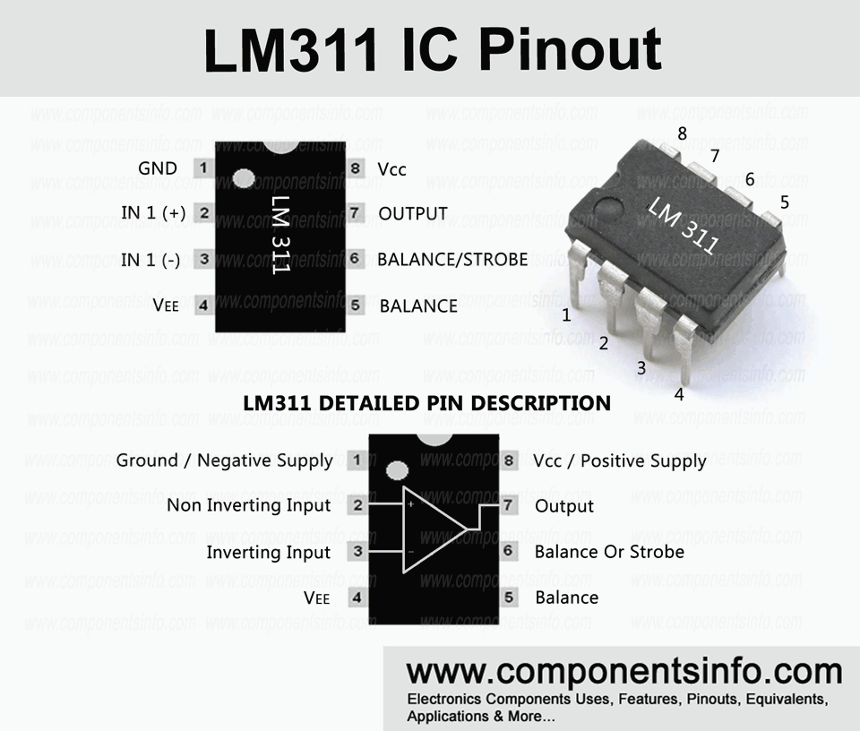
LM311 is a voltage comparator op amp IC with many good features; in this article we will discuss LM311 pinout, application, equivalent, descriptions,
also it helps to read the datasheet a bit
nova ingot
so how many leds will it drive?
cause if its one, ill have to get 4 or 5
nvr mnd, seems to be one
Order today, ships today. TLC374CN – Comparator Differential CMOS, MOS, Open-Drain, TTL 14-PDIP from Texas Instruments. Pricing and Availability on millions of electronic components from Digi-Key Electronics.
keen epoch
one might be a bit much. You'll have to use an common emitter amp after it
nova ingot
keen epoch
one might be a bit much. You'll have to use an common emitter amp after it
im confused
 nova ingot
https://www.instructables.com/Li-Ion-battery-level-indicator/ you linked this earlier

Instructables
Li - Ion Battery Level Indicator: Are you looking for a simple circuit to measure your Lithium Ion single cell charging and discharging level? Here is one chip circuit, powered up from the same Lithium Ion battery you want to measure.This circuit is design to measure 3.7V rechargeab…
https://www.digikey.com/en/products/detail/texas-instruments/LM339J/149031 if i got this would i just have to wire it up like in the diagram?
nova ingot
339n yes. i take it the 339j is too different
keen epoch
J looks like a slightly larger DIP package
nova ingot
im switching the 311 for a quad
keen epoch
*smaller
I can see if I have an LM339 floating around, probably not though
so I can kind of build it along side (time permitting)
nova ingot
the j is in stock at digi key and has a minimum of 1
keen epoch
this is the hard(er) part about that. Make sure theres not much difference between parts
But for your purposes, I think you are OK
Oh is it$13? lol
nova ingot
so the j has a max input of 3mv, and the n 5mv @30v
i may be looking at the wrong stat for voltages
here is the problem. it seems the j links to the same datasheet as the n
keen epoch
thats ok
keen epoch
nova ingot
i may be looking at the wrong stat for voltages
yea, I think you are. That sounds like offset voltage
Not a problem here
nova ingot
it looks like the only pin differences are the bottom 4 left are swapped


and i think i have a bad jst on my new power boost
keen epoch
GLGA is different
or what ever that package is. Just make sure you get a DIP 14 and you'll be ok
nova ingot
they both are
keen epoch
(afk a bit)
nova ingot
since the generall layouts are the same (just a few numbers swapped) it should wire up the exact same way right? i just have to make sure to arange the leds correctly
keen nacelle
@nova ingot not even the neopixel lights up?
you do need a * 2 on line 34:
def get_voltage(pin):
    return (pin.value * 3.3) / 65536 * 2
# TODO: multiply depend on how much voltage was cut```because the resistors are equal so we're reading half the battery voltage
keen nacelle
keen epoch
First you are reading (analog_in) and then an undefined pin called "pin"
Did you modify it? pin is defined in the function's scope; it doesn't need to be globally defined.
keen epoch
keen nacelle
Did you modify it? `pin` is defined in the function's scope; it doesn't need to ...
I think you replied to the wrong person. But like I said Im not familar with the language so I could be wrong
nova ingot
keen nacelle
<@!393614551985291264> not even the neopixel lights up?
just blinks red
keen nacelle
@nova ingot That code wouldn't blink if it was running, so it sounds like it crashed and the CircuitPython runtime is indicating that by blinking red. Maybe some libraries it needs aren't on the device. Can you check the Serial output using Mu Editor?
nova ingot
keen nacelle
@nova ingot Yep, it's missing the NeoPixel library. See https://circuitpython.org/libraries and copy the neopixel.mpy from the lib directory in that archive to the lib directory on the device.

The easiest way to program microcontrollers
nova ingot
ok. its putting out a string of numbers
keen nacelle
good, those are the voltages it's reading off the battery
nova ingot
ITS WORKING!
keen nacelle

nova ingot
i swapped out red for blue and green for purple so i would have colors that are different than what its showed and its shining blue!
thogh that may be because i dont have the voltage divider connected
keen nacelle
that sounds like it'd leave the pin floating, yes
nova ingot
SO, THE LED IN THE SWITCH IS PUPLE
[i feel like there is some coding missing in the pwm section
nova ingot
yes. after i tested it i reverted the colors to default
keen nacelle
and you changed it only with the wiring? or also in the code?
nova ingot
only in the code. while testing the neopix. the switch is the next test
its wired just like the qt py
does this essentially say to copy the color of the neopix?
 nova ingot
i think i may know part of the issue. the individual wires for the switch leds are all gnd and the common is power in. where do i wire the common
keen nacelle
what's it currently wired to?
nova ingot
3v
keen nacelle
that sounds reasonable
keen nacelle
checking
oh, hm
so the LEDs are lighting as expected, just the colors aren't matching the neopixel?
or are they lighting strangely too?
nova ingot
i think so. hard to tell as i have only full bats
keen nacelle
well let's make it sweep, then
nova ingot
neo pixel is right, switch is not
keen nacelle
try running that change
is it evident what that'll do?
if not I can describe my intent
nova ingot
it is sweeoing, but the colors are still wrong
green is purple
red, cyan
yellow blue'
its like its trying to mix but is getting it wrong
keen nacelle
hm
purple being red and blue?
or is there a purple LED?
okay new idea
can you get back to the serial and press ctrl-C?
then if you paste in the initialization for the LED pins you can set the PWM manually and test them that way
was that enough to make sense or do I need to be more specific?
er, ctrl-c and then enter
you'll enter an interactive mode where you can type/paste and execute statements in real time
keen nacelle
okay uh
so the imports this'll need are
from pwmio import PWMOut```then you can paste in the red_pwm = PWMOut(board.A1) # a green_pwm = PWMOut(board.A2) # b blue_pwm = PWMOut(board.A3) # d
and now you can set, for instance, red_pwm.duty_cycle = 0xffff and see what it does
(it should turn on the red LED all the way, or there may be a wiring problem)
nova ingot
im sure the wiring is right, ive triple checked it
nova ingot
=== import board
=== from pwmio import PWMOut
=== red_pwm = PWMOut(board.A1) # a
=== green_pwm = PWMOut(board.A2) # b
=== blue_pwm = PWMOut(board.A3) # d
=== red_pwm.duty_cycle = 0xffff
Traceback (most recent call last):
File "<stdin>", line 4, in <module>
ValueError: A1 in use
paste mode; Ctrl-C to cancel, Ctrl-D to finish
=== import board
=== from pwmio import PWMOut=== red_pwm = PWMOut(board.A1) # a
=== green_pwm = PWMOut(board.A2) # b
=== blue_pwm = PWMOut(board.A3) # d
=== red_pwm.duty_cycle = 0xffff
Traceback (most recent call last):
File "<stdin>", line 4, in <module>
ValueError: A1 in use
keen nacelle
try adding exit(0) as the first line of the code.py
then try again
I guess the existing code was already using the pins
nova ingot
return color_value * 0xffff // 255 could this be the issue
keen nacelle
oh!
uh, maybe
that's easy enough to test
you can paste that function in and feed it values and see if the right things come out
did the LEDs all behave as expected when you manually set them on/off then?
nova ingot
i manually changed that line in the code and it shifted colors
keen nacelle
from my poking at it, I don't think that line is the issue
65535
>>> 128 * 0xffff // 255
32896
>>> 0 * 0xffff // 255
0``` because these all look rightand yeah, it'll shift the colors if you change the code that determines the colors
but I don't know that it means it's the problem
I don't have more ideas yet - were you able to start setting PWM cycles in the realtime mode?
nova ingot
no. i couldnt figure it out
keen nacelle
did you try putting exit(0) as the first line so that the saved code didn't grab the pin?
nova ingot
import board
from pwmio import PWMOut
red_pwm = PWMOut(board.A1) # a
green_pwm = PWMOut(board.A2) # b
blue_pwm = PWMOut(board.A3) # d
red_pwm.duty_cycle = 0xffff
keen nacelle
what did you do with that / what were its results?
 nova ingot
many times
keen nacelle
hrm
I don't know what's happening, sorry
maybe those in #help-with-circuitpython have more ideas for things to check?
nova ingot
ill try tomorrow
keen nacelle
does it turn red if you replace everything in code.py with just the code you pasted?
nova ingot
@keen nacelle IT GOT FIXED
keen nacelle
@nova ingot Cool! What did you change?
nova ingot
def get_pwm(color_value):
return 0xffff - (color_value * 0xffff // 255)
keen nacelle
oh, inverted?
oh right because ground
that makes sense but I would not have guessed it
keen nacelle
“white - green” is a helpful way of thinking about it.
nova ingot
keen epoch
https://www.electronics-tutorials.ws/opamp/op-amp-comparator.html
hey. have a question. any quad comparator will work for the voltage meter right?
nova ingot
threads get archived when not used for a while. if you go to the hashtag at the top and click archived you will find them
keen epoch
ahh I didnt know that
keen epoch
nova ingot
hey. have a question. any quad comparator will work for the voltage meter right?
WHich one are you looking at specifically? Generally yes
nova ingot
Order today, ships today. LM339NE3 – Comparator Differential CMOS, MOS, Open-Collector, TTL 14-PDIP from Texas Instruments. Pricing and Availability on millions of electronic components from Digi-Key Electronics.
nova ingot
it seems to be the same as the other lm models
keen epoch
yes
but it will just have enough current to drive those LEDs
I dont know why they dont use transistors
nova ingot
ok, o it will drive the dels, but will it properly show the actual power level of the battery?
im gearing up for class on monday
keen epoch
Instructables
Li - Ion Battery Level Indicator: Are you looking for a simple circuit to measure your Lithium Ion single cell charging and discharging level? Here is one chip circuit, powered up from the same Lithium Ion battery you want to measure.This circuit is design to measure 3.7V rechargeab…
But yes
keen epoch
nova ingot
im gearing up for class on monday
What classes are you taking?
nova ingot
microcontroller programming. ill be learninf rasberry pi and python
keen epoch
Huh, those are more microcomputers. I would have figured arduino would be there :). Good luck and have fun
nova ingot
i plan on it
keen epoch
🥰
nova ingot
i am going to replicate the rover in both arduino and circuit python
keen epoch
which rover? There are many lol
nova ingot
i have the boards for it so i should be able to
pirover is what they are calling it
im also thinking of doing a battle bot and building a scorpion, just for fun and destruction
keen epoch
Oh I cant say heck
I always wanted to do one for the heck of it
Even figuring out armor would be fun. Hardened steel or not?
nova ingot
maybe we will meet up one day and battle it out
keen epoch
Yes and hopefully we have character sheets done and some good dice 😛
nova ingot
lol. the only characters i have are currently gods
keen epoch
Could always get into a battle mech and dual it out. I havent played MW5 but it looks pretty cool. I cant bring myself to buy new games strangely enough. Its been being dumped into my hobbies
But-Id be down. Depending on where you live
nova ingot
found out what kind of bot it is: Yahboom G1 Tank robot
apparently it includes a tool kit and i get to keep everything
keen epoch
Wow
$150
Not too expensive but expensive enough. Almost expensive as a text book
Oh man, you can have so much fun just to design power for the thing
Easy, off the shelf power? Ryobi Batteries. 18V will have more than enough. Want to switch it up? 40V batteries and then upgrade the motors to BLDC motors
Haha robot go vrrrrrr
nova ingot
i paid 250 for materials and am getting a tool kit and a multimeter
keen epoch
Did you get one of those trainer kits? Its a giant suitcase with a bread board + power supply
I still have mine from many years ago. I want to get rid of it..but Im like "Some day I'll use it". That day hasnt come
keen epoch
now you just get to do it at home :p
nova ingot
yeah. i actually plan on doing up a custom modular lab. put in a few standard components and a couple monitors, and placing in a rpi arduino and feather
didnt have those in the old electronic labs
keen epoch
Sounds interesting. Planning on getting a scope in there too?
nova ingot
maybe. right now im still figuring out what to add and how to incorporate it all.
keen epoch
https://www.aliexpress.com/item/1005003466564953.html?spm=a2g0o.ams_97944.topranking.2.2957hUBghUBgGt&pdp_ext_f={"ship_from":"CN","sku_id":"12000025916748508"}&scm=1007.26694.226824.0&scm_id=1007.26694.226824.0&scm-url=1007.26694.226824.0&pvid=155c47c4-3df7-4ccc-a06e-dc9182b45804&fromRankId=6426736&_t=fromRankId:6426736
Once you get your robot working you should incorporate something like that

aliexpress.com
Smarter Shopping, Better Living! Aliexpress.com
keen epoch
btw I looked in my stock and I dont have DIP comparators
keen epoch
Im gonna add an LM339 to my digikey order. It might be awhile before I pull the trigger though
 nova ingot

I call it the ma1a-alpha, aka church
I even mounted an altoids tin to the bottom for tools and extra parts
nova ingot
in the background yeah
its decent sized, id say as large as an xbox and as tall as that breadboard in the back, minus the camera
keen epoch
Wow lots of room for activities
nova ingot
the current chassis is a little small. that area with the boards behind the eyes is practically full, but there is a little room for other things. there are a few more servo pins, a few more sensor slots, and 2 more motor jts
plus alot of unused holes, 2 of which were used to mount the aloid tin to the bottom
 nova ingot
i think im gonna run my pip boy on a pi and use the micro controllers to drive various things
nova ingot
morning
keen epoch
Evening 🙂
nova ingot
ok. starting here, i will be stating my project and my progress.
the project lore:
My name is Annabelle and i was born in the wastelands of post nuclear war america. all my life my mother told me stories of the vault dwellers. so i made a decision to try to resurrect that technology. i learned how to seek out and refurbish old tech and slowly built up what i needed. the only thing missing was a case. luckily mentats tins were everywhere.
ok, real lore. i like taking scifi tech and pulling it into the real world. this time its the pipboy. i have wanted one since the first fallout game i ever played, but didnt like most of the commercially available ones. i also like the tactile feel of pots, switches, and buttons as well as altoid tins. so i decided to make a pipboy in a tin
what i want in it:
a fm radio
mp3 player
geiger counter
map with gps
inventory lists for food, tech, medical, books, and movies
a remote link cable for communicating with a pc
health screen which tells blood pressure and heart rate. this is a would be nice item
technically i already have the mp3 player, but i still cant get it to work. as part of the mp3 player system is a custom memory card. i aim to have both run by seperate MCUs but am unsure how to get them to talk to eachother right now. it is all wired up
for the remote link, im thinking of taking a 1/4'' audio jack and building a connector out of washers and gaskets to create contact points and allow data and audio transfer at the least, video at the most
nova ingot
and buried
anyways, im considering adding biotec to this, in the form of a heart rate monitor and maybe a body comp device if i can figure out how
hopefully i can interface with myfitnesspal
nova ingot
so, i started my enclosure and messed up already

I now have 2 extra holes and nothing to put in them
keen nacelle
Could it be antennas for show?
nova ingot
no. needs to be funtional, but i may be able to put wires to the main body, just need to seal it. still, dont like that i messed up
i even checked before drilling
nova ingot
My next project is a shell for my paintball gun that makes it look like a gun from halo
With an ammo counter
And an audio component for the gun sounds
nova ingot
my teacher just did the most awsome thing
keen epoch
what did they do?
nova ingot
they are giving me a free raspberry pi 3 for this project
nova ingot
well i have my contact pins, some comparators and even got some vintage audio stuff
keen nacelle
nova ingot
And an audio component for the gun sounds
Sounds fun! Getting small speakers that sound good may be challenging