#PCF8591 create command for WiFi
1 messages · Page 1 of 1 (latest)
 red anvil
For a shipmodel project I'm trying to program my Raspberry Pi controlled transmitter. After having established a WiFi connection I'm now trying to make the step to send a command with a value coming from a joystick (15 joysticks in total, each with 6 different functions controlled by a yet to be added additional parameter), with an add-on for the propulsion of the model.
I can't seem to figure out how to translate the raw values and then write them into the parameter command. Each of 15 joysticks has a 2-digit ID to make sure the correct joystick controls the correct function. How can I make this happen?
 delicate basin
To post code, see #welcome message. You can edit your existing messages to add the backticks.
I'm confused about the joysticks. These are analog-pot joysticks, not I2C, right?
red anvil
delicate basin
I'm confused about the joysticks. These are analog-pot joysticks, not I2C, right...
That is correct, I use 8 PCF8591's to translate the pot's resistance to something the Pi can understand
delicate basin
So here you are trying to read the analog value, I think?
            if joystick[key].value != 0:
                print(f"{key} is at a high level: {joystick[key].value}")
That is correct, it was an attempt to get the value into the "commando" parameter. This code was actually suggested by AI in VSCode because I had a list of print statements, 1 for each value, below it
delicate basin
this is just checking whether the value is 0 or not, as opposed to the full analog value, which can range from 0-65535. Because these are essentially analog pots, it may even be the case that the range does not start at 0, but a little bit above. Instead, print out .value in a loop, as you are doing, and move the joysticks to see what kind of range you are getting. You can take out the call to main() for now so you can just see what's going on with the analog values.
you are interested in the range, right? (figuring out where joystick is on the full range of movement)
red anvil
delicate basin
this is just checking whether the value is 0 or not, as opposed to the full anal...
Thanks, this will get me started indeed. Before prompting for a command I had this script running while moving the joysticks and saw widely different values, also per input. So 1 input would be between say 8500-12000 , another around the 30000 ar so.
delicate basin
even when they were in the same position (e.g. both in the middle?)
red anvil
delicate basin
you are interested in the range, right? (figuring out where joystick is on the f...
This would be necessary for translating the values correctly
delicate basin
the joysticks are wired with ground at one end and _3.3V at the other, is that right?
red anvil
delicate basin
even when they were in the same position (e.g. both in the middle?)
Yes, with the first input having the lowest value, going up in order to input 4 on the highest
delicate basin
and the slider pin is connected to each PCF8591 analog input pin?
delicate basin
red anvil
Yes, with the first input having the lowest value, going up in order to input 4 ...
I don't understand what you mean here. Do you have a schematic?
the joysticks should be wired in parallel
red anvil
delicate basin
the joysticks are wired with ground at one end and _3.3V at the other, is that r...
I use the Adafruit joysticks, 2 pots are on the same PCB and for sure share voltage and GND, the other joysticks are all hooked up to the power supply, I can check later today what voltage it provides, it might also be 5V
red anvil
delicate basin
I don't understand what you mean here. Do you have a schematic?
I'll work on a schematic shortly. For each PCF8591 there are 4 axis of joysticks connected, each axis has it's own input. When I read 1 PCF the values on AIN0 are the lowest, AIN1 is higher, AIN2 is even higher and AIN4 is the highest
delicate basin
use 3.3V for everything so that the I2C signals are at the 3.3v
red anvil
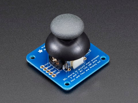
This mini-kit makes it easy to mount a PSP/Xbox-like thumb joystick to your project. The thumbstick is an analog joystick - more accurate and sensitive than just 'directional' ...
red anvil
delicate basin
use 3.3V for everything so that the I2C signals are at the 3.3v
I'll check and correct if needed
delicate basin
the Xout and Yout pins should each go to a separate PC8591 analog input pin. Vcc should be 3.3V and GND should be GND
red anvil
That is indeed how I wired the joysticks
delicate basin
at rest (not pushed), you should be getting a middle range value on Xout and Yout, I think, because the springs will bring the pot to around the middle.
so AIN0, 1,2,3 should all be around the same, at rest
sounds like something might be weird with the wiring
red anvil
These are the values from a test yesterday. There are a few PCF modules which are on the limit of what the wire can reach, the onboard LED of those PCF's is often completely off. Most of the PCF's are actually working fine for as far as I can tell
 delicate basin
i assume one PCF board is connected to two joysticks?
red anvil
The voltage after the TCA9548A I2C multiplexer is 5V indeed
delicate basin
a picture of the wiring of one of the PCF's and its connected joysticks would be helpful.
So you are not using the STEMMA/QT connectors?
do not run this further until you fix that, as you might be damaging the RPi I2C pins by driving them at 5v
red anvil
The joysticks are hidden below the plate, but can be accessed if needed, the plate is not permanently fixed in place

 red anvil
delicate basin
do not run this further until you fix that, as you might be damaging the RPi I2C...
red anvil
delicate basin
do not run this further until you fix that, as you might be damaging the RPi I2C...
No, on the joysticks I soldered wires directly onto the board, so no Dupont connectors like on the PCF
delicate basin
those are not our PCF8591 boards. Please give a link to the supplier
red anvil
delicate basin
do not run this further until you fix that, as you might be damaging the RPi I2C...
The power is passed around the TCA9548A and is only there connected to 5V since the TCA9548A doesn't have power connectors for the I2C lines
delicate basin
is it our TCA9548A board or another supplier?
red anvil
delicate basin
is it our TCA9548A board or another supplier?
This one is from Adafruit, it's visible hanging in the overall view below the line of PCF's
red anvil
delicate basin
those are not our PCF8591 boards. Please give a link to the supplier

Beschrijving:
- De modulechip maakt gebruik van PCF8951
- De module ondersteunt de externe 4-kanaals spanningsingang (ingangbereik 0-5 V).
- De module integreert de fotoweerstand, die de omgevingslichtintensiteit met AD kan vastleggen.
- Module geïntegreerde thermistor, kan door AD nauwke...
delicate basin
to be clear, this is a Raspberry Pi, not a Pi Pico, is that right?
red anvil
It's a Raspberry Pi 4 model B
delicate basin
that PCF8591 module has extra stuff on it: photoresistor, temp sensor, etc. If those are connected to the ADC pins, then you will get bad values. Maybe removing the jumpers disconnects those?? There is no schematic! Ugh
also there are various resistors on the bottom, doing I don't know what
there are dozens of these listed on Amazon, but I can't find any schematics
ok, I think this is generically known as a "YL-40" module
red anvil
delicate basin
that PCF8591 module has extra stuff on it: photoresistor, temp sensor, etc. If t...
I have indeed removed the jumpers because of this reason. For as far as I can find on the internet, that is the way te remove them
It's a good thing that the issue with the high voltage is addressed, however my question is about the program. I want the value that is changed (IE I move a joystick) to be added to the 2 digits from the input into the parameter "commando" so it will be send to the shipmodel. How can I make that happen?
delicate basin
... so in any case, wire 3.3V to the TCA multiplexer, yes
you can convert the 0-66535 value to the range you want, and then use str() to convert the integer to a string that you can send in the URL to http://192.168.178.80:8000/cmd/{command}. I don't know the protocol that is being used there, though
do you have any spare PCF8591 modules? If so, connect one directly to the RPi, remove the jumpers, as you have, and try various voltages on the A0-A3 pins to see if you are getting reasonable values. I am still suspicious of the wiring.
Also, the PCF8591 can be configured as differential or single-ended ADC, and if it's configured wrong then you'll get weird values
red anvil
delicate basin
do you have any spare PCF8591 modules? If so, connect one directly to the RPi, r...
I will see what I can do about that. I'm in the process of adding a 3,3V regulator, and I won't be checking anything before that properly works
red anvil
delicate basin
you can convert the 0-66535 value to the range you want, and then use `str()` to...
On the receiving end I have FastAPI running
delicate basin
make sure you tie the ground connections of everything together
fastapi is very general. I would need to see the webserver script to see how it's receiving things
red anvil
That is currently also work in progress. I think I should be able to control the propulsion if I can somehow get it to either read the Board and Busio libraries from Circuitpython or if that doesn't work in the same program that is creating a FastAPI server then I'd need a way to get the command from the server in the program controlling the main propulsion
This is the server with control for the propulsion
delicate basin
So the essence is
    srv = commando[:3]
    angle = int(commando[3:])
Exactly
And that is what I'm trying to create from the transmitter side where my question began
delicate basin
the single command is the servo id plus the angle. You haven't converted to angle on the sending side yet. Maybe you don't want to do that? Maybe convert on the receiving side. That is more flexible, I would think. Just report the raw values to the receiving side, and have it figure out what to do (denoise, adjust for individual controls, etc.)
I would think there's a way in fastapi to send a command with args, instead of stuffing it all together into a single string. But I don't know anything about it
red anvil
delicate basin
I would think there's a way in fastapi to send a command with args, instead of s...
If it works better than I'm all for it
delicate basin
I think it will be easier to code.
so are there two separate computers here? The RPi reading the control panel, and the receiver on the "ship"? Is this a remote-control model, or is it some game board? The reason to use the web interface is because the control panel is separate from the thing being controlled.
where did you get the "cmd" example for the FastAPI?
red anvil
delicate basin
the single command is the servo id plus the angle. You haven't converted to angl...
My general idea is to have as much generalised as possible a command and have the boat figure out what to do with it. So a range of 0-255 is pretty general and then have the boat rescale the value to 0-180 with some means of adjustments to both range and midpoint as well. This all considering that each joystick axis has about 6 different functions which are to be controlled by a selector on the yet to be made UI on a 10" touchscreen
delicate basin
so the boat is separate, battery powered, on the pond or whatever?
advantage of putting the specialization on the boat is that a single control panel can control different kinds of boats
disadvantage is that you don't specialize the control panel with labels for what that particular boat needs
red anvil
delicate basin
so are there two separate computers here? The RPi reading the control panel, and...
This is a remote controlled ship model, both the transmitter with it's joysticks and the boat itself are battery powered. The model will be able to do basically everything the real ship can
delicate basin
so I'm not sure about that division of labor after all
it depends on where, whether you need flexibility
red anvil
delicate basin
advantage of putting the specialization on the boat is that a single control pan...
That is the reason for this setup. I will make an add-on for controlling the propulsion on each model like the real ship is controlled
delicate basin
so then it doesn't matter so much
what kind of computer is on the boat? Another Raspberry pi or something weaker?
red anvil
delicate basin
disadvantage is that you don't specialize the control panel with labels for what...
That indeed is a small disadvantage though it makes is so much easier to use the same program on the transmitter to control the second model
delicate basin
now I'm thinking that the boat specialization should be done on the control panel side, because it's probably easier to deal with that when setting things up and debugging.
it's a lot easier to connect your control panel to a laptop on shore on a table than bring back the boat each time to edit its program
red anvil
delicate basin
what kind of computer is on the boat? Another Raspberry pi or something weaker?
Another Pi 4 model B indeed. This in part because of the camera systems (7 camera's now to be mounted on an ESP32 per camera, then 2 more connected through USB to the Pi because those are in ROV's and WiFi won't penetrate water
delicate basin
of course, you could remotely login to the boat and edit its program too
red anvil
delicate basin
it's a lot easier to connect your control panel to a laptop on shore on a table ...
There is 10" touchscreen and 2 USB-ports in the side. Simply connecting a keyboard pretty much makes it a laptop
red anvil
delicate basin
it's a lot easier to connect your control panel to a laptop on shore on a table ...
In the boat I keep the Pi within reach to connect a touchscreen and keyboard if need be so I can troubleshoot the boat almost as easy as the transmitter
delicate basin
still maybe easier to tweak the controller than the boat. "Oh, I need to adjust the servo angle a bit."
though there is calibration too. Two identical boats might still need slightly different servo angles to turn a certain amount due to slight mechanical differences.
I will leave you to decide that 🙂 . In any case, next steps here are to document the wiring with a schematic, check it, and maybe check a standalone PCF8591 + joystick to understand what is going on with the weird values
red anvil
delicate basin
still maybe easier to tweak the controller than the boat. "Oh, I need to adjust ...
I thought of implementing perhaps even some sort of file holding the parameters for all the different in- outputs. This would be especially useful for cranes which have a limited height they can reach and preferably won't go below their resting point as well
delicate basin
a config file sounds like a good idea. Basically it is scaling, but it might also be reversal (use a negative scale). You could use JSON for that
red anvil
delicate basin
though there is calibration too. Two identical boats might still need slightly d...
This has been on my mind for the last like 10 years or so and I'm filling in the details on the fly
delicate basin
is this a one-person project?
red anvil
delicate basin
a config file sounds like a good idea. Basically it is scaling, but it might als...
Sounds like a plan indeed. I'd like to be able to modify it's values from the transmitter as need be
delicate basin
also think about making various things table driven from the config file or elsehwere. Any time you see repetitive code like this:
out16 = port1.get_pin(0)
out16.switch_to_output(value=True)
out17 = port1.get_pin(1)
out17.switch_to_output(value=True)
out18 = port1.get_pin(2)
out18.switch_to_output(value=True)
For 99% it is, my father has a lot more knowledge of programming then I do, though tailored to data rather then robotics. I started this project 18 years ago with this incredibly high goal and very little experience even building a shipmodel
delicate basin
... it is crying out to be described as data and to use arrays instead of separate names. out[port_number] instead of out16, out17, etc.
red anvil
delicate basin
also think about making various things table driven from the config file or else...
That's a good plan. Will this also work if those outputs are not logically connected to a command? I can see it work perfectly if output 1 is called with command 1 and 2 for 2 and so on. That is not the case here. I started making a list of all the functions, devided by 4 sections of shipmodel, then started appointing commands and joysticks to them. In terms of control I chose to keep things as intiutive as possible so 1 crane has functions controlled by 3 joysticks spread over 2 PCF's. Not because that is the minimum amount needed, but to keep up/down on the X axis of the joystick and left-right on the Y axis which is very intuitive considering the way the joysticks are mounted
delicate basin
well, in FastAPI everything does not have to be one kind of URL that is just cmd:
http://x.x.x.x/servo?change=<ii>
http://x.x.x.x/servopair?change1=<i>&change2=<j>
you could also decide to do something like:
http://x.x.x.x/rudder?angle=...
or
http://x.x.x.x/rudder?change...
q is whether to send the incremental change or the value you want. You use the joysticks to nudge the rudder one way or the other (unlike a ship's wheel!)
Don't know if you want to name the objects you are controlling, or just speak in terms of servos
red anvil
I now connected the 3,3V regulator succesfully (I checked the voltage) and now the numbers are more clear. I noticed that once I started moving a joystick the values dropped to an almost useful scale of 215,512 and 768 for as far as I could see.
 delicate basin
those values still look weird, because if you are not touching the joysticks they should all be centered and you should be reading about 65536/2 (roughly) at each analog input
https://realpython.com/fastapi-python-web-apis/ I am getting deas from
red anvil
delicate basin
you could also decide to do something like:
`http://x.x.x.x/rudder?angle=...`
or...
That sounds like a plan to me. Though I'd like to stick with my 3 digit ID's to keep it all completely general. The first digit is used to indicate what sort of thing I'm controlling, with 0 being propulsion, and A-Y being selectable from the touchscreen
red anvil
delicate basin
those values still look weird, because if you are not touching the joysticks the...
That would be very nice indeed
delicate basin
is your father a software professional
delicate basin
red anvil
That would be very nice indeed
yes, that is why i am suspicious of the wiring
red anvil
delicate basin
q is whether to send the incremental change or the value you want. You use the j...
Sending the change for the most part would actually be very useful, espacially for all functions that have a resting position that is not in the center like cranes.
red anvil
delicate basin
is your father a software professional
In data he is, yes. He was the one who came up with FastAPI.
red anvil
delicate basin
yes, that is why i am suspicious of the wiring
I'll check the wiring and I'll run my multimeter across lots more wires then I have now
delicate basin
so he would have a lot of ideas about this, and how to structure your code, the config files, the FastAPI URL's etc. In other words, the abstractions you want.
red anvil
delicate basin
<https://realpython.com/fastapi-python-web-apis/> I am getting deas from
Thanks, I'll be reading that too
red anvil
delicate basin
so he would have a lot of ideas about this, and how to structure your code, the ...
Yes, and he also suggested breaking up the commands in sections
delicate basin
also use the voltmeter to read the A<n> values at the PCF boards yourself as you move the joysticks
red anvil
I will
red anvil
The first test results are in, it would help if the pots actually work. On the first 6 axis, 2 are giving 0V, the others range from 0 for maximum in 1 direction to almost 3,3V in the other, some come close to this but don't reach 0V and don't reach 3V. Actually, all joysticks are broken on at least 1 axis
delicate basin
red anvil
The first test results are in, it would help if the pots actually work. On the f...
it sounds like some of the pots are wired in series?
Vcc on all the pots should be connected together, whether by daisy-chaining or by going back to a common point. GND should similarly all be wired together. Then each Xout and Yout go to separate Ain pins.
did you solder the joysticks to the boards? We are talking about genuine Adafruit 480 512 boards?
red anvil
These indeed are the genuine Adafruit boards and the joysticks are soldered to the board. I now also measured the resistance of the pots (+ wire from the multimeter to the Xout or Yout and the - to the ground), this gives wildly different values for various pots. I appear to have 1 working pot which measured 3K-ish Ohm with the pot in the center, 0 at 1 end and 5K-ish Ohm on the other and that on both axis. All other pots had these values at best on 1 axis and some even measured close to or at 0 Ohm regardless of it's position.
Should the pots reach 10K Ohm?
delicate basin
can you unplug the pots from the PCF boards, so that there is no connection to anything other than your ohmmeter? Are the Vcc's all tied together and the same for the GND's?
I don't want anything on the PCF boards to affect the measurements
do you have any unused ones you can take a picture of?
and measure resistance on unused ones
red anvil
I have now taken the PCF's away and got halfway through testing the resistance with nothing attached to the joysticks. 1 joystick passed the test taking 1 loose joystick as baseline (highest resistance of all), but most don't reach the 5K Ohm on the 1 end and also don't quite reach 0 Ohm on the other end. Multimeter is set to 20K Ohm
delicate basin
so you are measuring resistance between Xout and GND or VCC and also between Yout and GND or VCC?
I would expect them not to quite get to 5k or 0
I don't have a sample of this to test, unfortunately
could you take a sharp picture of one of the "bad" ones from the bottom and top? Take off the knob


 delicate basin
Those don't look our genuine boards. See pictures here https://www.adafruit.com/product/512
This mini-kit makes it easy to mount a PSP/Xbox-like thumb joystick to your project. The thumbstick is an analog joystick - more accurate and sensitive than just 'directional' ...
the silkscreen does not match what's on our boards. And there is no Adafruit "star"
soldering of the upper left one and the upper middle one could be better 🙂
I have to go out now for a couple of hours. I'll check back later
red anvil
This is the top side

It does match yours, you designed them to be top mounted, that would leave them exposed to rain in my case
delicate basin
ah ok, well, I really have to go, will check back
red anvil
It seemed best not to change too much, I might have accidentally connected things the wrong way around
delicate basin
make sure you are not using the SEL pin by mistake. But it's ok to mount the headers on the bottom
red anvil
That is good to know
delicate basin
I found I had one of these after all. Some measurements:
between VCC and GND: 4.8k ohms
between VCC and Xout: 46 - 4.8k, 3.65k mid position
between VCC and Yout: 50 - 4.8k, 3.75k mid position
red anvil
delicate basin
I found I had one of these after all. Some measurements:
between VCC and GND: 4....
I had a few which feel in those parameters
delicate basin
These are pretty much exactly what I would expect. The basic pots are 10k each, so between VCC and GND they are in parallel, hence the 4.8k.
The othermeasurements are kind of as expected, though I might have expected the mid position to be more like 2.4k than 3.6k
you might try touching up the soldering on some of the "bad" ones
the unassmelbed ones should be similar. If all the unassembled ones test "good", then I suspect soldering
red anvil
That sounds reasonable indeed. I'll touch the soldering up as soon as I can
red anvil
It's not the soldering, the value remain way of. Also, when I start moving a joystick slowly it's not scaling like I would expect with resistance even going towards 6K Ohm at about 3/4
delicate basin
i see a small "dead zone" in one direction but not the other on each axis
this I think is the spring mechanics
red anvil
Do you mean that a fysical spring can affect the resistance? And would that be repairable?
delicate basin
red anvil
Do you mean that a fysical spring can affect the resistance? And would that be r...
i mean that in one direction there is a little dead zone before moving the joystick causes the resistance to change
delicate basin
maybe try measuring the resistance directly from the pins on the back of the breakout board
 red anvil
delicate basin
maybe try measuring the resistance directly from the pins on the back of the bre...
red anvil
delicate basin
maybe try measuring the resistance directly from the pins on the back of the bre...
I have, that gave the same result
delicate basin
this is the upper left joystock in your photos. There should be ~10k across the outside pins in each boxed set. The middle pin is the slider
the one I marked with an arrow has questionable soldering, but it's hard for me to see
red anvil
delicate basin
this is the upper left joystock in your photos. There should be ~10k across the ...
I don't think that would be 10K, because the GND and VCC are still connected to one another
delicate basin
ah, you're right, so 5k
red anvil
delicate basin
the one I marked with an arrow has questionable soldering, but it's hard for me ...
It's got a bit rusty after sitting idle for almost 6 years now. There are 5 which I bought less then a year ago, the others are over 3 years old. None have seen any use other then the occasional wobble to get a little feel for things
delicate basin
I searched the support threads in https://forums.adafruit.com with 512 joystick. There are some complaints about dead spots, but I didn't see anyone complain that the potentiometers were bad.
you could look at those in detail
it's possible they went bad over the years, especially if there was moisture. pot wipers can become erratic. I have noticed this in much older electronic equipment. They become scratchy
red anvil
Even if they've been inside all the time?
delicate basin
the middle top looks quite corroded??
or is that just solder flux?
it's true, mine is probably the same vintage and works fine
did you use electronics solder (not plumbing solder) on these when you solder them up?
red anvil
delicate basin
did you use electronics solder (not plumbing solder) on these when you solder th...
I did use electronics solder indeed and no flux
delicate basin
that's good. did you try these joysticks at the time and they were ok?
red anvil
Unfortunately no, I'm only recently starting to get a bit to grips with the programming side of the project
Behind the scenes I have tested a PCF using your test program and a 10K pot and proved that at least 1 PCF is giving proper voltage readings.
Though it appears that something is off with the TCA9648A in between the PCF and the Pi. I tested with a new PCF connected straight to the Pi and got properly changing values both in voltage and in raw value (basically 512 through almost 65K) but switching this setup (so the 2 10K Ohm pots) to a PCF connected through the TCA9648A gives mostly constant values though at times it does jump around
The GND of the TCA9648A goes directly to the Pi which has a Geekworm X735 V3.0 hat for handling power. From it's 5V pin runs the power (including GND) for all the devices including those connected behind the TCA9648A. On the X735 board the GND is connected to the DC connector powered directly (fused) by a 4S LiPo battery of 11000mAh. Can this cause the problems with the readings?
delicate basin
red anvil
The GND of the TCA9648A goes directly to the Pi which has a Geekworm X735 V3.0 h...
The grounds should be tied together. Otherwise the ADC doesn't have a stable reference voltage to compare to
the I2C multiplexer should be supplied with 3.3V, not 5v, so that its connections to the RPI will be 3.3v compatible
red anvil
I'll be working on that shortly
delicate basin
getting late there; I'll be around tomorrow
red anvil
I have tried to combine the GND of both the I2C systems (straight from the Pi, the other being all behind the TCA9548A) and then tried to see what addresses are connected to the TCA9548A (your example code) but then the I2C couldn't find anything attached anymore. Then I tried to remove the devices one by one and then reconnecting one by one and suddenly the i2cdetect found devices again. Ran the TCA9548A example code again and then all devices were lost again. At this point I'm considering taking all the wiring out and starting all over again. I'm thinking of routing the power lines across all PCB's so the 3,3V and the GND all come from the Pi rather then using ribbon cables and then combining all like 23 wires in 1 place causing a huge cluster of wires
I don't have any pullup resistors added and I haven't removed any on the PCB's
delicate basin
These kinds of "daisy-chain" jumpers seem to be made just by one company, but they would help: https://schmartboard.com/daisy-chained-jumpers/. An alternative would be to connect all the ground jumpers to a a few terminal blocks (like a multiway Wago connector or a screw terminal block).
It is still strange that you were seeing bad resistance values on the disconnected joysticks. If they don't look rusty or damaged or whatever, I am at a loss to explain that.
red anvil
delicate basin
These kinds of "daisy-chain" jumpers seem to be made just by one company, but th...
I was thinking more along these lines. Where VCC and GND have 2 wires soldered to each connector, one coming from the power supply, the other continuing to the next board. The SDA and SCL lines will remain ribbon cables.
 delicate basin
red anvil
I was thinking more along these lines. Where VCC and GND have 2 wires soldered t...
delicate basin
red anvil
I was thinking more along these lines. Where VCC and GND have 2 wires soldered t...
disadvantage is that it's harder to disassemble due to the soldered terminals. Something like this could be used for the power wiring: https://www.karwei.nl/assortiment/wago-lasklem-5-voudig-0-14-4mm2-hersluitbaar-8-stuks/p/B225693
easily available at a hardware store
I think they will hold dupont jumper ends
or just bare wires if you have already cut the jumpers in half
red anvil
delicate basin
disadvantage is that it's harder to disassemble due to the soldered terminals. S...
That's true, on the other hand, the connection will be rock solid, even when the wire is at the limit like I have now for 2 PCF's. Added advantage is that the the power wiring is easily recognizable and takes up much less space. Even the Wago's (of which I have a few laying around) will make a mess again. And if something would be wrong with the power cables it's quickly visible where it goes wrong, while even the Wago's it will be a search to find the wrong connection. So trouble shooting will be much more easy. This then also applies to the SDA and SCL lines because those are not obstructed anymore by a huge cluster of power lines.
red anvil
delicate basin
I think they will hold dupont jumper ends
They do indeed, there perfectly fine connectors
red anvil
delicate basin
It is still strange that you were seeing bad resistance values on the disconnect...
I agree it would be very strange. Fact is though that we've spent a good deal of time on parts that now cheaper to replace then what has been spent discussing what is wrong, even though there's good value in there too
delicate basin
sounds good; you have a better idea of how you want to arrange things.
Our I2C breakouts are all redesigned now to have chainable STEMMA/QT connectors: https://www.adafruit.com/product/4648

Measuring voltage and adjusting it is what electronics is all about so you won’t get far without friends like the Adafruit PCF8591 Quad 8-bit ADC + 8-bit DAC combo. Analog ...
8-channel ADC: https://www.adafruit.com/product/5836

Many microcontrollers have ADCs these days, for reading analog/resistive sensors like potentiometers, thermistors, LDR light sensors, etc. but sometimes you need MOAR! Or maybe you're ...
red anvil
delicate basin
Our I2C breakouts are all redesigned now to have chainable STEMMA/QT connectors:...
I am considering this option as back-up for if the current PCF's prove to be faulty as well. I'd need to look into the STEMMA/ Qwiic options, these would be the only devices that have them so that might be a challenge. The ADS7830 would actually be cheaper then replacing all the current PCF's so that is a plus and it would seem it's hardly bigger but I'd need half the amount which is a big advantage.
delicate basin
I know it's traditional to use analog spring-loaded joysticks, I think partly because of how old radio-controlled models worked, but since this could be whatever you want, have you considered simple digital joysticks for some things, or rotary encoders, or potentiometers that don't spring back to center? For instance the rudder wheel could be a potentiometer. The crane control could be just a digital on/off joystick, etc.
red anvil
A hall sensor in the place of the potmeter would indeed improve reliability. For the main propulsion I use AS5600's to measure the angle of the propulsion (360 degree rotatable azipods) and potmeters for their fysical resistance for the throttle lever on top. This helps to keep the lever in place, taking away the challenge of designing a proper spring system which would also make controlling the model a bit more difficult considering I can indepently control of total of 3 (normally 1 will be retracted into the hull, so normally 2) azipods and 2 bow thrusters. The same Adafruit joysticks will be used for controlling the bow thrusters.
Replacing these joysticks wouldn't make sense because with a press on a button on the touchscreen that joystick goes from controlling a crane to putting a lifeboat overboard, tick that button again and now it's controlling the lifeboat. In total I have 6 functions groups for the joysticks so I can have basically all PWM controlled functions (except for the fire pumps, they'll have a slider on the touchscreen) will be controlled by these 15 joysticks.
delicate basin
much more complicated than I realized! 🙂
red anvil
I can understand that. For reference, in the model itself we're talking 8 16 channel servo modules, 4-6 16 channel MCP23017's (I replaced a few by TLC5947's), 2 LMS9DS1's (1 for back-up and error detection), a couple of TCA9548A's to make it all controllable. A MCP2221A makes a second I2C network so that if a non propulsion device (IE 2 PWM modules, a PCF for registring how far the retractable asipod is retracted and 1 LSM9DS1 to solve the adress issue straight away) I can still steer my model back to shore. This actually fits very well in the spirits of the real ship which has it's engine rooms devided such that fire in 1 area on the ship can never make it loose control
red anvil
https://nl.aliexpress.com/item/1005010490860801.html?spm=a2g0o.detail.pcDetailTopMoreOtherSeller.10.f0e9WifKWifKYc&gps-id=pcDetailTopMoreOtherSeller&scm=1007.40050.354490.0&scm_id=1007.40050.354490.0&scm-url=1007.40050.354490.0&pvid=bab9262d-a290-4b44-b8b2-4d7d85c82041&_t=gps-id:pcDetailTopMoreOtherSeller,scm-url:1007.40050.354490.0,pvid:bab9262d-a290-4b44-b8b2-4d7d85c82041,tpp_buckets:668%232846%238114%231999&pdp_ext_f={"order"%3A"172"%2C"spu_best_type"%3A"price"%2C"eval"%3A"1"%2C"sceneId"%3A"30050"%2C"fromPage"%3A"recommend"}&pdp_npi=6%40dis!EUR!4.39!4.39!!!33.98!33.98!%402103835e17735860167263307e8337!12000052580802466!rec!NL!4169443729!XZ!1!0!n_tag%3A-29919%3Bd%3Ae9bce063%3Bm03_new_user%3A-29895&utparam-url=scene%3ApcDetailTopMoreOtherSeller|query_from%3A|x_object_id%3A1005010490860801|_p_origin_prod%3A
I might replace the potmeters with these, hoping that the current boards and top will fit on these. That would be an upgrade and repair in 1
red anvil
Can one use each channel on the TCA9548A as an individual I2C network? So can I connect several devices, each with a unique I2C address, to the same channel on the TCA9548A? In the example code I see sensors being called upon simply by the channel which they're attached too, can I add an I2C address there?
red anvil
red anvil
Can one use each channel on the TCA9548A as an individual I2C network? So can I ...
I found the answer here: https://learn.adafruit.com/working-with-multiple-i2c-devices/circuitpython-6

A more indepth look at dealing with I2C address conflicts.