#SST flash debugging
1 messages · Page 1 of 1 (latest)
 gaunt pilot
You could skip getting serial console working if you start up in user-invoked safe mode. That should eliminate the need to mount CIRCUITPY early, because main.c won't try to run boot.py, safemode.py, or code.py. Then you can delay or just comment out mounting the filesystem early.
One thing I have done is to insert code I want to run into an innocuous user-invokable routine in, say, microcontroller or micrcontroller.cpu, like .temperature or maybe something better. Then I can make that code happen when I'm already in the REPL. So you could put the mounting in there, say. Then you can just log with mp_printf(&mp_plat_print, ...) and it will come out on USB serial.
Re SWD: did it work at all? Did you use the onboard gdb debug interface? If that doesn't work, you could use the header near the power pins. The tab on the SWD plug should point toward the edge of the board with the USB connectors
I made these sorts of aliases for ease in getting the gdb interface up with the J-Link: alias gdbserver-same54p20a='JLinkGDBServer -device ATSAME54P20A -if SWD'
i am talking about the small 10-pin SWD header
 radiant scroll
On the SWD front, I've attached the J-Link to the correct header on board in the correct orientation. I can start pyocd, and it successfully connects to SWD over CMSIS-DAP. I have not tried JLinkGDBServer, but will.
gaunt pilot
i have never used ocd that successfully. The J-Link software is better
radiant scroll
Where pyocd collapses is when I connect to 3333 from GDB.
Got it. I'll go that route.
radiant scroll
With an unmodified CP image flashed, I get the LED strobe, but no further. If I reset during the strobe, it does not enter safe mode.
gaunt pilot
that is what Ross was getting too
radiant scroll
This board with the new flash part is a special kind of special.
gaunt pilot
I have aliases to invoke gdb also, like alias tm0-gdb='gdb-multiarch build-trinket_m0/firmware.elf'
so I specify the .elf file on the command line. I can't remember why I started using gdb-multiarch -- I think maybe it was to get the gdb python support to work
there is also stuff in .gdbinit there to use the svd_gdb.py library to access the registers by name
Scott set that up years ago
radiant scroll
Which port does JLinkGDBServer listen on?
gaunt pilot
3333
NO WRONG :2331
define jlink
target extended-remote :2331
end
in .gdbinit
so I start up gdb, per the alias above, or by hand (I have aliases for the common boards but not all)
then I do jlink in gdb, and it connects. when I recompile, I do jload to get it to reflash, or jloadc to reflash and restart immediately
this is just my workflow, that I made up, to avoid having to remember the indivual commands
I was doing a lot of work on setting the fuses right, so there are some commands in there to read and change the fuses in various ways
there is a j-link interface right on the board, at the DBG USB port
or I thought so,
maybe I am wrong, maybe that is just the ICE
radiant scroll
OK, a tiny bit of progress. I'm doing all of this by hand right now. I can target remote:2331, monitor reset, cont. It behaves as I've described, then hangs up. ctl-c breaks me into reset_into_safe_mode.
gaunt pilot
ok great, you can set a breakpoint a bit earlier to get a stack trace about who invoked safe mode. I'll look and try to remember: it's been a year or two
radiant scroll
I'll go over your .gdbinit, but for now I prefer to keep everything completely transparent.
gaunt pilot
did you just set a breakpoint on reset_into_safe_mode()?
radiant scroll
It's a hard fault triggering safe mode.
gaunt pilot
so if you set a breakpoint there, you will catch who's calling it
and you can see the reason too
it's SAFE_MODE_HARD_FAULT?
radiant scroll
Yup. HardFault_Handler is calling reset_into_safe_mode.
gaunt pilot
is there a useful backtrace?
radiant scroll
This is where I needed to get, I can carry on from here. I'll need to build with symbols for the bt to be truly useful. I appreciate your help.
gaunt pilot
that sounds like a secondary bug. I guess you want to do some breakpointing/bisecting to find where it's hanging up
and re the serial port thing: you were trying to set the console to go to some serial pins but you weren't seeing any output?
I rarely do that, so I"m not sure of the compile flag settings
radiant scroll
Now that I've got SWD working, I can make progress. So many broken tools.
gaunt pilot
🙂
radiant scroll
No problem with the gcc flags. That's second nature to me. With SWD I may not need the serial console.
gaunt pilot
very occasionally I have to power-cycle the J-Link, but that was rare. mon reset is your friend in gdb to get the hw back to a good state
I think that was only when I was messing with fuse setting. There was a trick to get it to actually write the fuses, but never mind that for this
radiant scroll
I'll keep you posted. Thanks again, sincerely.
gaunt pilot
i cut my teeth on samd gdb debugging in the beginning, but it's kind of like a piano piece I learned 8 years ago and only play once a year now
radiant scroll
You were spot on, Dan. Hard fault is secondary due to uninited vfs->next, failure to mount the fs was one more level up in the failure chain, and, of course, flash failure to init was the root cause.
gaunt pilot
the flash failure to init should really go into safe mode with reason SAFE_MODE_NO_CIRCUITPY. It does do that sometimes already with other errors (like can't init the filesystem) (takes care not to recurse if we are already in that safe mode)
There is SAFE_MODE_FLASH_WRITE_FAIL but that's too specific, you're not trying to write. I think that may be used only for internal flash, but not deliberately.
radiant scroll
You're right. Noted. I'll see if I can add that once I've shot the flash bug.
I've worked my way to original bug reported in #10172, the hard fault in memcpy during an attempt to initialize the fs. Progress!
radiant scroll
This may be it: With my updated toml we're hanging up in wait_for_flash_ready. It's got a hard-coded assumption re: status that's probably not right for this flash part. Back to the datasheet...
But first, a walk, a shower, and some breakfast!
radiant scroll
Well that's...interesting. Contrary to the datasheet, the SST26VF064B doesn't appear to reset the WEL (Write Enable Latch) status bit after completing a Page Program. The BUSY bit comes down, but the WEL stays up. I'm going to poke around some more to be certain we're not doing something strange like reading the wrong register.
 primal plank
👋 so I'm on the thread
radiant scroll
I bypassed the WEL bit test, and now we're back to hard faulting. Now it looks like the Page Program ops are never actually writing to the flash. Pass me a shovel...
(That explains why the WEL bit never comes down)
primal plank
https://www.adafruit.com/product/5315 or https://www.digikey.com/short/f28zdvjb can be really helpful for flash debugging

This SOIC Test Clip is a great way to test and connect to Flash memory, EEPROMs or other 8-SOIC chips, with pinpoint accuracy and NO soldering! It's sort of like an alligator ...
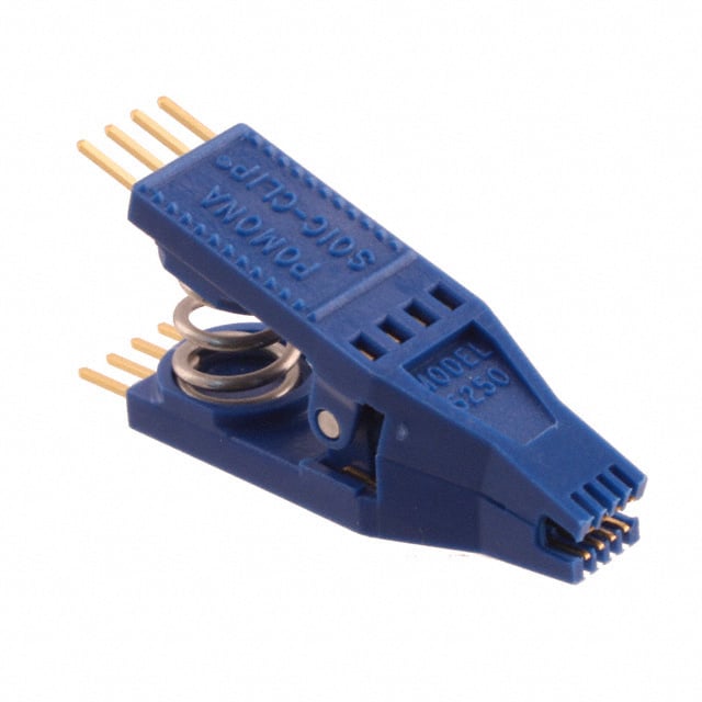
DigiKey Electronics
Order today, ships today. 5250 – SOIC, 0.15 to 0.35" Wide Test Clip 8 (2 x 4) from Pomona Electronics. Pricing and Availability on millions of electronic components from Digi-Key Electronics.
try lowering the clock speed of the flash if you haven't already
radiant scroll
So the question is: how did this ever work? What's happening is that write_flash is calling spi_flash_write_data but not the generic version as would be correct for external flash. Instead, it's calling the specialized version in ports/atmel-samd/supervisor. My, oh my.
For this board with its external flash, we need to exclude the specialized flash functions so they don't override the generic functions.
(Thanks for the tool tips, I'll order one)
primal plank
No, the custom one is to use the QSPI peripheral
you'll need a logic analyzer with it
radiant scroll
I see, my bad. I got excited there for a second.
I see we're reading flash in QUAD depending on the board, but are always writing in SINGLE unconditionally.
radiant scroll
The SST26VF064B is unusual in that it has two separate controls for quad spi mode. In the configuration register the IOC bit controls the operation of the WP# and HOLD# pins switching them between use as data (IOC=1) or WP# and HOLD# (IOC=0). Additionally, there are a pair of ops for enabling/resetting quad mode: EQIO(0x38, Enter Quad I/O) and RSTQIO(0xFF, Reset Quad I/O). CP is not set up to use these ops, so I've tried running the part in single mode. No luck.
gaunt pilot
forwarding a few messages from other thread
@neon lark @radiant scroll I compared the datasheets for SST26VF016B and SST26VF064B, and they seem virtually identical, including the 38H operation, etc.
The SST26VF016B and SST26VF064B were PR'd https://github.com/adafruit/nvm.toml/pull/11 by flyerink, who is/was a Microchip employee, Frenkie Wang, in Shenzhen.
That PR says they were tested and worked. So SST26VF032B should be workable too. https://github.com/adafruit/circuitpython/issues/10172 says something changed at CircuitPython 8.2.0 that broke it, but the testing was on an Xplained board with non-SST flash, I think. I pinged @flyerink about this: https://github.com/adafruit/nvm.toml/pull/11#issuecomment-2796895713. flyerink has a microchip email address you can see in their profile.
@neon lark 👆
radiant scroll
gaunt pilot
That PR says they were tested and worked. So SST26VF032B should be workable too....
The mention of 8.2.0 in issue #10172 is likely a red herring. Problems with the SST26VF064B go back to at least version 8.1.0 as shown in issue #8047.
 neon lark
I sent an invite to my guy in memory products, so hopefully he can help
radiant scroll
gaunt pilot
The SST26VF016B and SST26VF064B were PR'd <https://github.com/adafruit/nvm.toml/...
The SST26VF016B is not used by any boards supported by CircuitPython, so it's likely that it's never been tested with CircuitPython.
gaunt pilot
I don't know what flyerink meant when they said it was tested; it would be good to know
looking at the data sheets, I think the 16, 32, and 64 all operate the same way
radiant scroll
I'm walking methodically through init. I've found that we inadvertently cleared the IOC bit in supervisor_flash_init by zeroing the config register after setting it in spi_flash_init_device. After fixing that, still failing in same way: wait_for_flash_ready hanging up due to WEL bit in status register never coming down after a page program command (0x02). If I ignore the WEL bit, CP thinks the flash write has completed, but nothing is actually written to the flash.
I'm working under the assumption that whatever the 016 or 064 was tested with, it wasn't CircuitPython. I'm now looking closely at the protection mechanisms on the parts.
gaunt pilot
radiant scroll
I'm walking methodically through init. I've found that we inadvertently cleared ...
If you are getting stuck, it would be fine to wait for the Microchip support engineer and pose q's to them
radiant scroll
@gaunt pilot @primal plank @neon lark Got it! CircuitPython now successfully initializes a CIRCUITPY drive on the SST26VF064B flash. The root cause is the unusual protection mechanism built into the part. It's a hack at this point, but I've disabled protection by issuing a ULBPR (0x98, Global Block-Protection Unlock) in supervisor_flash_init() like this:
    #if 0
    if (flash_device->has_sector_protection) {
        write_enable();

        // Turn off sector protection
        uint8_t data[1] = {0x00};
        spi_flash_write_command(CMD_WRITE_STATUS_BYTE1, data, 1);
    }
    #else
    // Experimental: Unlock all block-protection bits
    spi_flash_command(CMD_ENABLE_WRITE);
    // Global Block-Protection Unlock
    spi_flash_command(0x98);
    #endif
The code that's #if'd out is where the IOC bit gets cleared in error.
Once I determined that it was the sector erase prior to the page program that was actually failing, it pointed me to the part's protection mechanism. The rest was straight forward. @gaunt pilot and @primal plank we'll need to chat about how to fix this properly.
 mental hollow
Nice, just made an account to help, that block protection can be tricky.
Ross was letting me know
radiant scroll
mental hollow
Nice, just made an account to help, that block protection can be tricky.
I think for CircuitPython we'll want to turn it off completely, similar to the hack above. Is there something more subtle you can suggest?
mental hollow
radiant scroll
I think for CircuitPython we'll want to turn it off completely, similar to the h...
Unfortunately, the Block protection is enabled after power cycling, so the quickest way to unlock it is the Global Unlock command. I had to go through and double check but I do not believe this can be disabled.
radiant scroll
mental hollow
Unfortunately, the Block protection is enabled after power cycling, so the quick...
Thanks for the double check. Using the ULBPR should be fine.
gaunt pilot
@neon lark could you try this build, which is for xplained same54? https://github.com/adafruit/circuitpython/actions/runs/14451538234/artifacts/2941892628 ? It's from @radiant scroll's pull request https://github.com/adafruit/circuitpython/pull/10249 to fix how SST flash chips work. It should also load on the curiosity board, though the pin defs will be wrong. But see if CIRCUITPY comes up. This build also has support for 16, 32, and 64 versions of the SST chip.
neon lark
@gaunt pilot I am having issues flashing to the SAME54 Xplained Pro.
Here's what I have tried:
Connected to PC, was not detected. Checked SentinelOne and confirmed it was not getting blocked.
Tried connecting Atmel ICE and flashing UF2 via SWD debug connector (same way I flashed the binary you sent last week for the Nano board).
That gives this error:

Sentinel One just updated. It was blocking it.
Working on getting it whitelisted.
So I just discovered that Sentinel One was not blocking the SAME54 Xplained Pro (but the error screenshot above prevented flashing). But it did block the Curiosity board when I flashed the UF2.
gaunt pilot
neon lark
So I just discovered that Sentinel One was not blocking the SAME54 Xplained Pro ...
TCF is something in Eclipse: "Target Communication Framework". You flash the UF2 by uploading to the BOOT drive on the xplained board. So you have to load the UF2 bootloader on the xplained board. I thought you did that last week, but maybe not.
neon lark
I didn't find an Xplained board last week. I just found one today though
BOOT drive never appeared for the Xplained board. Tried both Target and Debug USB connectors
gaunt pilot
are you flashing https://github.com/adafruit/uf2-samdx1/releases/download/v3.16.0/bootloader-same54_xplained-v3.16.0.bin to the xplained board?
That has to be there, then you'll be able to double-click to get the BOOT drive for that bootloader
neon lark
Sorry, was having an old man moment! 🤣
Just flashed the binary. Then got the Sentinel One blocking thing. Currently putting in a request to have the SAME54 Xplained whitelisted
neon lark
Have had the SAME54 Xplained Pro whitelisted on Sentinel One.
Programmed it with the binary you linked yesterday.
When I double-click the reset button, no xxxxBOOT drives appears in Windows Explorer
gaunt pilot
@Ross I programmed the xplained board with a J-Link connected to the SWD connector with that .bin, and double-click shows E54XBOOT. Just to confirm, the USB cable is connected to the "TARGET USB" jack?
radiant scroll
As Dan said, also when you double-click reset, LED0 should start pulsing, not flashing.
gaunt pilot
(not sure how to program using the DEBUG USB jack without using Atmel Studio, which I don't have installed)
look like that capability is no longer there by default: https://www.segger.com/products/debug-probes/j-link/models/other-j-links/j-link-edbg/
radiant scroll
One other thing, for your whitelisting, the id will be 0x00b5/0x239a running the UF2 bootloader, running CircuitPython it will be 0x80b6/0x239a.
neon lark
I have Atmel Studio installed. I tried programming the binary using the EDBG. For some reason that autodetects it as an SAMD51P20A. I was able to program the binary and see LED0 pulsing. But no drive.
Wait, sentinel one is blocking again 😖
gaunt pilot
do you have to open a ticket for each of these 😦
radiant scroll
I feel for you.
neon lark
gaunt pilot
do you have to open a ticket for each of these 😦
Yup. It's exhausting 🤦♂️
gaunt pilot
I guess they won't wildcard exempt 0x239a as VID
neon lark
Ok, flashed the binary and saw E54XBOOT.
Pressed reset and Sentinel One blocked it again. Put in a new whitelist request
gaunt pilot
@neon lark assuming this works, the next step is to update the curiosity board def repo to the tip of adafruit/main so you can pick up the changes. You could rebase or merge from upstream (adafruit).
neon lark
I had the resubmit the whitelist request this morning as it was blocked (again) by sentinel one when I tried to flash the UF2 to E54XBOOT drive
primal plank
is it done based on usb vid/pid? you could change it
neon lark
It's done on the USB serial numbers that come up when it connects
primal plank
you could hard code that in tinyusb
neon lark
Sorry I was out sick yesterday.
Looks like the SAME54 Xplained Pro is now whitelisted. I have it connected to Target USB. It shows up as having 7.95MB storage.
I can program it (just a simple LED toggle) and copy library files to it successfully.
neon lark
@gaunt pilot was the microchip chat thread deleted? I didn't at it in the archived threads.
I'm trying to find a message that was part of it
gaunt pilot
you should be able to click the spool of thread icon at the top and see it. It's not listed visibly after several days of inactivity
neon lark
gaunt pilot
<@408440154814939136> assuming this works, the next step is to update the curios...
@gaunt pilot I will need help with this
gaunt pilot
neon lark
<@329766224093249548> I will need help with this
did you make any changes besides adding the board to ports/atmel-samd/boards ? You could bring main on your fork up to date, and then create a branch for the board locally. Then copy the board files to that branch, commit them, and submit a PR to adafruit/circuitpython.
# copy the curiosity board files from your development branch off somewhere else.
git remote add adafruit https://github.com/adafruit/circuitpython
git checkout main
git pull --ff-only adafruit main
git submodule update --init --filter=blob:none   # bring the submodules up to date
git checkout -b curiosity-board
# copy the board files back to this new branch
# try a build
# when it's ok:
git commit -a
git push
# now go to https://github.com/adafruit/circuitpython. You should see a box with a button about "recent pushes", and making a pull request. Go ahead and do that.
I'm going over all of the pin and SERCOM configurations with a fine tooth comb to make sure they're correct.
Then I will start on the above instructions
gaunt pilot
are you testing them in CIrcuitPython itself? That may be the easiest way to surface any issues? And did you get it loaded on the curiosity board itself?
neon lark
I have CP on the curiosity board (sans the SST26VF0xxB support).
I can toggle IO pins and confirm with logic analyzer.
The SERCOMs have been a bit more challenging so far
gaunt pilot
neon lark
I have CP on the curiosity board (sans the SST26VF0xxB support).
I can toggle IO...
if you go ahead and make a draft PR as above, it will have the SST support in the builds (or your local build)
i.e. bringing it up to date on main will incorporate the SST fixes
i have the schematic saved somewhere, I thought. could you say more about the sercom challenges?
like, are you creating, say, a UART on some designated pins, but it's saying "Invalid pins"?
neon lark
I'm still pretty new to 32-bit, was an 8-bit guy for several years.
I have multiple SPI buses on my board. I have one each for SD card, LCD, and an extra general purpose one. The general purpose one would likely become the one that users would utilize when working with. I guess that would become my default one?
gaunt pilot
yes, for connecting external stuff. The SD one would have board.SD_MOSI, etc. and the LCD one would have board.LCD_MOSI (or DISPLAY_MOSI or whtaeever)
so you could just test each one with busio.SPI(mosi=..., miso=..., sck=...) and if that doesn't error then you are fine. Maybe I am saying something obvious to you
and the display may be write only, so no miso needed
neon lark
gaunt pilot
if you go ahead and make a draft PR as above, it will have the SST support in th...
Ok, I synced my fork with Adafruits main branch.
Then built the new firmware, put the board into bootloader mode and dropped the firmware.uf2 file onto the CPYNANOBOOT drive.
CIRCUITPY drive doesn't appear, I tried resetting the board as well.
Flashing the default-objects-no-external-flash.uf2 you sent last week works though.
Not sure what I'm doing wrong in my build.
gaunt pilot
neon lark
Ok, I synced my fork with Adafruits main branch.
Then built the new firmware, p...
can you get to the REPL via /dev/ttyACM0?
oh, wait, you're on windows, ok, via Tera Term or similar
when you're connected to the REPL, and you press the reset button, what shows up in the REPL window?
neon lark
Windows Device Manager sees it as COM40.
In TeraTerm nothing comes up initially, or when I press the reset button
gaunt pilot
so you if unplug it the COM40 goes away?
neon lark
Yes
gaunt pilot
does ctrl-C do anything?
neon lark
Checked several times that sentinel one is not blocking it
gaunt pilot
when you press reset, do you see anything interesting on the RGB LED?
gaunt pilot
that's good, that means it's coming up. You would press reset during those flashes to get it into safe mode
is the source for that build pushed to your repo?
neon lark
I'll push it now
gaunt pilot
you could try another build with INTERNAL_FLASH_FILESYSTEM=1 in mpconfigboard.mk. Also did you do a make clean BOARD=... beforehand or remove the build-* directory before rebuidling?
this is good, you made a PR against adafruit/circuitpython. We can make this a draft and work on it easily.
neon lark
I didn't do a make clean. I'll try that now
I just pushed my changes to the development branch
gaunt pilot
So there is an SST26VF016B on the test board right now?
neon lark
No, it's a 64. Need to update the files. Doh!
gaunt pilot
you don't need to do a clean build every time, just when you've updated stuff like the error messages, or some underlying sw.
neon lark
Ok, updated mpconfig.mk for the SST26VF064B.
Rebuilt and flashed the uf2.
It appears in Device Manager, but doesn't show in TeraTerm. Tried CTRL-C, resetting but doesn't show.
gaunt pilot
there is an mpconfigboard.h and a pins.c at the top level of your repo, which should not be there. Could you git rm them and commit and push?
(and make sure they are not inadvertently the latest versions of those files instead of being in the board directory)
neon lark
Fixed
gaunt pilot
ok, I changed your build slightly, doing
EXTERNAL_FLASH_DEVICES = "N25Q256A,SST26VF064B"
so I could try loading it on the xplained board. With INTERNAL_FLASH_FILESYSTEM = 1 it did come up. with QSPI_FLASH_FILESYSTEM = 1 it did not.
so that's fishy -- I wonder if one of the QSPI pins is getting used for something else.
no, pins look ok
neon lark
QSPI pins only being used for that
 gaunt pilot
I can't find my schematic for your curiosity board right now. Could you give me a link or upload it? I commented out #define EXTERNAL_FLASH_QSPI_DUAL in mpconfigboard.h and that helped on the xplained board, but I don't know if you are using the flash in dual or quad mode
neon lark
gaunt pilot
hmm, you must be using it in quad mode, because of the schematic above, and the quad mode pins are PA08-PA011, but in our code, it says the dual mode pins are PA08, PA09, PB10, PB11 WRONG: PB10 and PB11 are QSPI SCK and CS
anyway, it is quad mode, so remove that EXTERNAL_FLASH_QSPI_DUAL line. I can upload my build here
neon lark
When I created the schematic, I based it of the Feather M4 CAN.
I'm not sure if the Feather is dual or quad mode?
gaunt pilot
that's my build, with quad mode, and support for the SST 64 chip.
Feather M4 CAN does NOT have WRONG -- looking in the wrong fileEXTERNAL_FLASH_QSPI_DUAL set. It uses quad mode
anyway, try that uf2 above
my mistake about the pin difference, but I have no idea why we used dual mode on the Feather CAN. The SST may be different for DUAL mode and it's not being set up properly for that. But we can use quad mode anyway, I would think. I will see if there's a reason for the dual mode on the feather
no reason that I can see. Feather M4 CAN is one of the few boards I don't have on the shelf, so can't test it with quad mode
neon lark
That works, Windows sees the 8MB flash and I can program it.
Thank you!
gaunt pilot
yay!!
If you change the external flash devices line to :
EXTERNAL_FLASH_DEVICES = "N25Q256A,SST26VF016B,SST26VF032B,SST26VF064B"
it will support all those possibilities. Not sure if the N25 chip even has the same footprint, so you could delete that if it doesn't make sense
radiant scroll
Just tuned in to the flash show. Bravo for getting it working!
neon lark
radiant scroll
Just tuned in to the flash show. Bravo for getting it working!
Thank you @radiant scroll and @gaunt pilot !
radiant scroll
Goes for me, too.💪
neon lark
Now just need to test the buses and I should be good to go!
gaunt pilot
The pull-request version still has the #define EXTERNAL_FLASH_QSPI_DUAL in mpconfigboard.h. Delete that line.
neon lark
Do I just delete it, or change to:
#define EXTERNAL_FLASH_QSPI_QUAD ?
gaunt pilot
it defaults to quad