
#Velocity's Macro Armpad and ring
1 messages · Page 1 of 1 (latest)
 lime veldt
Research says that some of my best options may be a Feather nRF52840 Express https://core-electronics.com.au/adafruit-feather-nrf52840-express.html
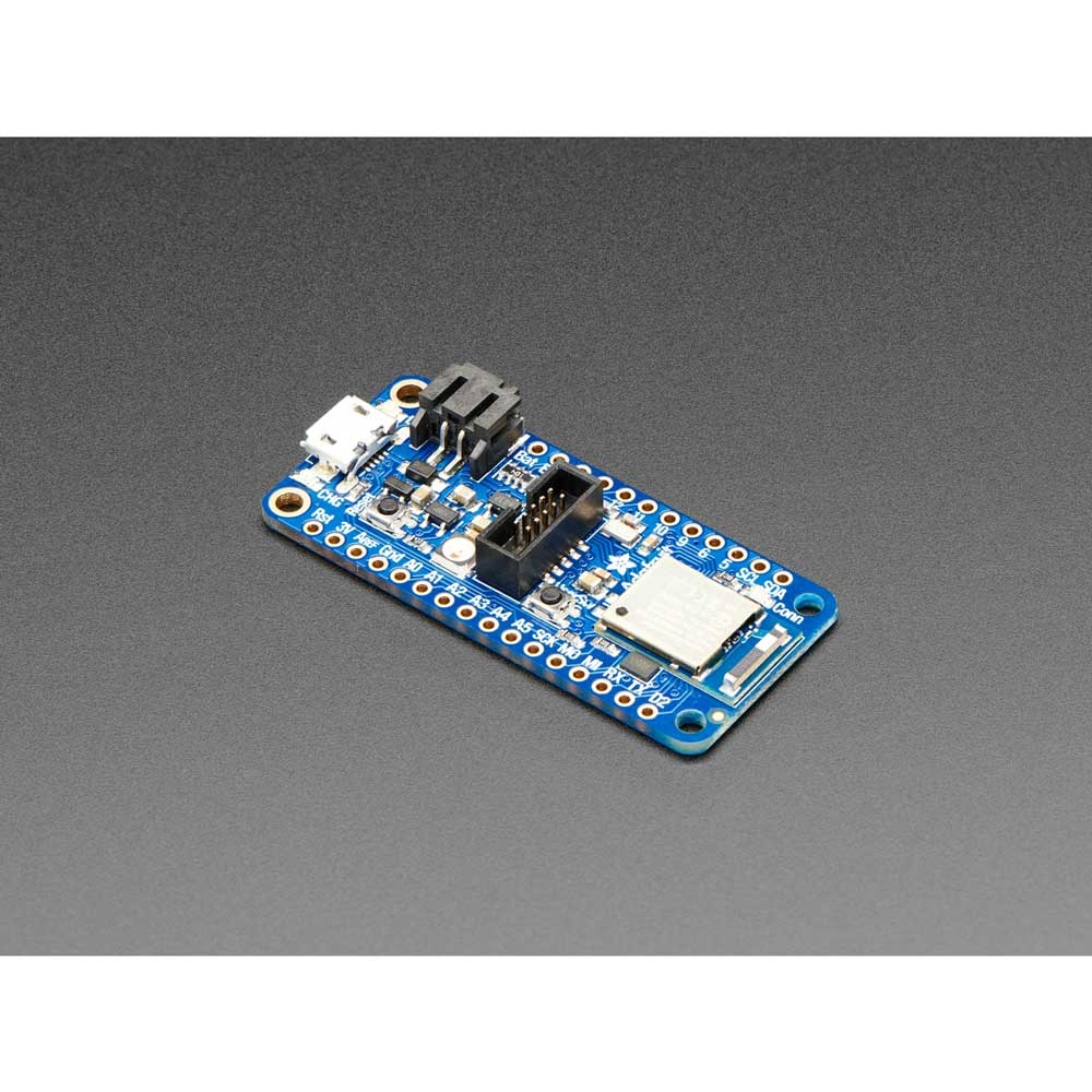
The Adafruit Feather nRF52840 Express is the new Feather family member with Bluetooth Low Energy and native USB support featuring the nRF52840! It's Adafruit's take on...
I think theres about 21 useable pins

And hopefully a 2400mah battery should work fine, hoping to get about atleast 10 hours of battery life out of it https://core-electronics.com.au/polymer-lithium-ion-battery-2400mah.html

Welcome to the awesomeness that is LiPo batteries. Polymer Lithium Ion batteries offer superior energy density with this 2400mAh battery being on 6mm in height!
For dials, I got 2 of these

And for the keypad, got this old keyswitch tester I've always wanted to turn into a macro pad

Im willing to accept all advice and criticisms, I'm not knowledgeable in electronics, not yet, so any help is great
If im good at anything, its 3d modeling
 atomic swan
I may have missed it, but on a first run through I didn't see any explanation of a keypad matrix.
That page gives a really good description of exactly how they're wired, and how you work them.
The example they show has 16 keys using only 8 wires altogether. A good rule of thumb is to make the array as close to square as possible, that will tend to minimize the wire count.
e.g. for a 20 key matrix, you'd want to go 5 by 4, using 9 wires. You could do it 10 by 2, but that would be 12 wires: that's three more.
lime veldt
atomic swan
I may have missed it, but on a first run through I didn't see any explanation o...
You wouldnt of missed it, I dont know much about a keypad matrix
Currently testing some placements

So a keypad matrix needs good code to handle multiple buttons it seems?
atomic swan
It's not trivial. Not just the code, but the wiring as well. Think what would happen if the driver lines were "active high", meaning they have transistors that drive them both up and down. For any of the driver wires, only one of those is ever turned on at a time, so that's OK in isolation.
Now think what will happen if you drive one line low, and leave the others high, and then press two keys on a common output, but one connected to the low driver, and another to one of the highs.
That means you'd have one driver trying to pull the line high, and another trying to pull it low, effectively a short from vcc to ground through two transistors. That's bad.
The usual solution is to use single ended drivers with pullup resistors to vcc. In that scenario, pressing two keys at once doesn't cause a dangeous short.
All that said, the programming for it needs to be done carefully to handle multiple keys being pressed at once.
lime veldt
atomic swan
The usual solution is to use single ended drivers with pullup resistors to vcc. ...
Well, thats not scary at all
atomic swan
Then you need to worry about de-bounce, since many switches don't have a perfect switch, they open and close a few times before closing permanently. Again, there's many explanations of that, but it is something to be aware of.
That said, all this is well documented if you take the time to look on the web, and ask here. Many of us (me included) have made one or more of these mistakes in the past, and can provide help with getting your setup going.
lime veldt
I hope to get it made up right, if i can use less cables, saving ports and room, it be perfect
atomic swan
Another random thought. When making the case, make the sides shorter, and then rather than have it be an inverted U shape, make it just a gentle curve. Then put some slots in the sides so you can thread a padded cloth band though it, using velcro to hold it closed. That'll "breathe" a lot better, so your wrist won't get so hot and sweaty. Think like a NATO watch band but on major steroids.
lime veldt
Oh the part that sits on the arm would be the bottom plate, its only curved on the part that touches my arm, the part that connects to the rest would be flat
lime veldt


This OLED display module uses the SSD1306 drive chip, has 128x32 self-illuminating white pixels, and adopts the back chip-mounting pad design. Small size, the length...
Chosen screen


