#help-with-rp2040-pio
1 messages · Page 2 of 1
 small meteor
 lament hearth
dont know where to start getting that coded onto a pico
small meteor
You just press the white button while plugging the Pico into your USB port.
Then let it go - it mounts like a thumb drive does.
 distant spade
@lament hearth your best bet is to wait for rotaryio support I think
circuitpython is much easier than C
small meteor
With CircuitPython you do that (above) one time only, then can play for weeks without doing it a second time. ;)
lament hearth
im ok with the basics, in C, micropython and circuitpython, I got lots of LEDS flashing on and off-board, but i dont know enough about porting Arduino C code onto python
small meteor
A lot of ordinary Arduino code is apt to be similar.
But if it calls an Arduino library, that can be a issue.
So you can read the keyboard and print messages all day long without using a lot of Arduino Libraries.
lament hearth
yes it calls keyboard and usb joystick as its a HID USB controller
its a matrix button box
small meteor
Look at HID as advanced.
The pico is too new for a lot of example code to be available.
lament hearth
it seems that way 😦 So prob best to wait for the arduino C port...then I can use my existing code.
small meteor
follow the TAGS of this project:
https://github.com/wa1tnr/camelforth-rp2040-aU
rpi-rp2 rp2040 rpi-pico raspberry-pi-pico
Those are the main ones I've seen so far.
pico is too generic and produces false leads.
lament hearth
that leads to a forth interpreter for the rp2040?
small meteor
raspberry-pi-pico has 27 entries.
That one does, yeah.
But it's tagged with the usual tags for this hardware.
The pio is like a do-everything generic port that can emulate others.
Like spi or i2c or even pwm.
That's extra - they have those ports as well, I think.
lament hearth
i understand pwm but not spi or 12c or what they do or if they are important
small meteor
i2c is most of the modern add-on devices. uses SDA and SCL.
spi uses MOSI and MISO.
They're both 'serial ports' of a different kind.
lament hearth
soz means nothing to me, too many acronyms Im not familiar with 😦
small meteor
Well you buy a gadget like an LCD or a graphic display, and you find out you need one of those to talk to it.
lament hearth
ah ok
small meteor
It's better to know ahead of time which one you want to work with i2c or spi.
Then choose a compatible gadget like a temperature sensor or a compass.
lament hearth
i dont think i need either for my project!
small meteor
Sometimes watching a video helps to at least grasp what can be done.
A demo in person (a friend or taking a class) is even better.
lament hearth
sure, youtube is great for that but for me its either too basic or too complicated, learning curve is v steep, I got on ok with arduino and teensy examples, adapting them to what i needed and understanding how the code worked, but with the pico i just hit a wall
small meteor
It's important to want what you haveinstead of having what you want too. ;)
I felt that way in the bookstore: either too simple or way too baroque. ;)
Do you have a pico board with you?
lament hearth
yep
small meteor
You can just drag and drop the .UF2 from my project in that link above.
It starts a Forth intepreter and has a blink word you can type.
Just press ENTER a few times to align the USB port to the baud rate then type blink and press ENTER.
It'll blink the LED once.
(You use a hyperterm like program to talk to it on the USB port)
🕳️ 🐇
If you get that far, type:
ok WORDS
(the ok is prompt, you don't type it)
lament hearth
what do you use as editor - thonny or Mu or s/thing else?
small meteor
Oh I use vim only, pretty much, or any GUI editor I have laying around.
I do like mu .. just installed it the other day.
The lower half of mu is like that hyperterm I spoke about. Or Serial Monitor in Arduino IDE.
thonny looks interesting as well.
Old school is SCREEN.
lament hearth
i had circuitpython on the pico before, nothings happening
small meteor
The pico has to present as a thumb drive like device to your operating system.
Just like a lot of cameras, the Kindle, or your smartphone does.
lament hearth
yep it does when i plug it in with button pressed
small meteor
Right. That's where you drag and drop a .UF2 file.
lament hearth
yep did that
small meteor
So what do you have then?
lament hearth
nothing!
small meteor
You need to connect to the pico via USB and hyperterm, putty and the like.
To type at it, and see messages back from it.
lament hearth
putty?
small meteor
What operating system do you use and what terminal program do you like to work with?
small meteor
Yes that one. drag and drop that one. ;)
lament hearth
i have mu and thonny, i like neither 😉
small meteor
So hyperterm in Windows, or putty, or any other terminal.
You can use the Serial Monitor in Arduino, maybe.
lament hearth
no it doesnt like the [pico as pico running circuitpython, doesnt recognise the board
small meteor
Well I am not a Windows user so I don't know exactly how it recognized the USB port to talk to it.
Before mu Adafruit used to recommend a few other programs.
They all do the very same thing: establish a typewritten conversation with a text interpreter.
lament hearth
should camelforth be calling up stuff from other libraries to use?
small meteor
No it'll run the way it is. ;)
(technically I think they call it 'static linked libraries' or something like that)
From your computer's perspective, it's just a USB port with an active conversation on it.
(sending text messages back and forth; keystrokes from you, and reports from the Pico in text messages to hyperterm, Serial Monitor and the like).
lament hearth
neither thonny nor mu is recognising anything running on the pico and the led is dormant
small meteor
The LED won't blink until you type blink and press ENTER. ;)
lament hearth
but i need a working terminal to type blink, and i dont have that part
small meteor
Yeah you need that for a lot of things with microcontrollers.
I thought putty was supposed to be good.
hyperterm came with a lot of versions of Windows.
lament hearth
not mine! Looking up putty now
i appreciate your time but this is taking me down an entirely different complicated route i dont need to follow.
 blazing dawn
how can I find the micropython machine module ? is it available on github? Im intrested in the machine.UART class .
distant spade
@blazing dawn it's built into micropython

GitHub
MicroPython - a lean and efficient Python implementation for microcontrollers and constrained systems - micropython/micropython
 candid seal
Just curious: Is IRQ support planned to remain out of scope for CircuitPython?
 latent venture
candid seal
Just curious: Is IRQ support planned to remain out of scope for CircuitPython?
latent venture
candid seal
Just curious: Is IRQ support planned to remain out of scope for CircuitPython?
That would interest me too!
candid seal
yeah. I watched the livestream deep dive and they were talking about interesting ways to bring threading support to circuitpython for this chip in the future. Obviously there's already work going in to support the PIO. Would be really neat to see irq support added as well so we can take full advantage of the pico in circuitpy (and leverage all the existing circuitpy libs)
 fast perch
I have a "silly PIO idea" -- a neopixel decoder. 🤪
distant spade
@candid seal @latent venture I think the start of it would simply being able to read and write the irq state from CP. Having it actually interrupt Python code is something I'm less keen on.
irq allocation is a bit tricky since we abstract SM assignment further
small meteor
I saw that the remnants of CircuitPython was still in the flash chip after loading CamelForth. ;)
I guess you have to 'nuke' it to remove that (don't want to remove it).
This is the part where I 'should' take the time to learn how to integrate a VM written in C, into CircuitPython. ;)
distant spade
I've got some newer PIO changes in https://github.com/tannewt/circuitpython/tree/rp2040_audiobusio

GitHub
CircuitPython, an education focused port of MicroPython. - tannewt/circuitpython
blazing dawn
distant spade
<@!493827757243891715> it's built into micropython
Aha, thanks!
small meteor
Does anyone knows if it is possiable that the pico communicate with the ESP32
 storm heath
@small meteor What is the ESP32 doing ? I have connected an ESP32 Airlift breakout to my Pico and it works. Are you using something like that or are you just trying to communicate with the ESP32 via the UART?
small meteor
I made a burgler alrm with the pico and now I want that the ESP32 send a message to my mobile phone you think tht is possiable
storm heath
What is running on the ESP32? Which ESP32 board is it?
small meteor
Oh on the moment I have not the esp32 working but I am running troug Windows and micropython
On this moment I am running the pico
esp32 wroom
storm heath
I don't see why you cannot have the Pico Communicate to the ESP32 via the the UART -- I have not done it myself but it should be possible. As I noted, an Airlift works well with the Pico and is a lot simpler. https://www.adafruit.com/product/4201
small meteor
jerryn: thank you
storm heath
You're welcome -- Good luck!
 wheat holly
is pico pins voltage == esp32 pins voltage?
storm heath
I'm not sure what you mean -- both use 3.3V for GPIO signals.
@small meteor are you planning to use WiFi or BLE on the ESP32?
small meteor
Wifi
storm heath
ok -- just curious.
 muted shoal
storm heath
I don't see why you cannot have the Pico Communicate to the ESP32 via the the UA...
muted shoal
storm heath
I don't see why you cannot have the Pico Communicate to the ESP32 via the the UA...
I attempted doing similar with an esp8266 and am unable to get the ESP to really respond to any sort of AT command sent to it. unsure what the issue with that is, it is definitely connected to the device, as i can sometimes get it to spit out some form of data, idunno :/
 sour path
distant spade
I've got some newer PIO changes in https://github.com/tannewt/circuitpython/tree...
sour path
distant spade
I've got some newer PIO changes in https://github.com/tannewt/circuitpython/tree...
Is stride_in_bytes to support multiple bytes per pull?
distant spade
@sour path yup!
muted shoal
anyone have any tips for seeing/fixing the uart issue above?
storm heath
@muted shoal just to clarify, you have an ESP8266 with the AT-Firmware connected to a Pico? What are you running on the Pico?
muted shoal
oh wait I had to reflash it with a correct AT firmware?
storm heath
What is on the ESP8266?
muted shoal
At the moment an arduino script that isn't capable of really interacting with anything
I assumed it was directly interacting with it without the need for a different firmware
I'll try flashing it and seeing if it works
storm heath
THat may explain why it does not respond to AT commands 😉
muted shoal
yes that would likely explain it
small meteor
I used this advice to -Wall to the c compiler for RP2040 SDK projects:
https://stackoverflow.com/questions/14231292/cmake-and-compiler-warnings
example of that use is here:
https://github.com/wa1tnr/camelforth-rp2040-aU/commit/a32cbd623d54ae2308f4dfdf609454597cd9642c
 silent zealot
Are there any resources out yet about IR receivers with the Pi Pico? More specifically, are there IR micropython libraries that will work with the Pico?
candid seal
There are some Micropython ir libs listed here you can take a look at to see if they’ll work. But I haven’t tried yet.

GitHub
A curated list of awesome MicroPython libraries, frameworks, software and resources. - mcauser/awesome-micropython
And if you don’t need Micropython, the CPY irremote library may work (again haven’t personally tried)

GitHub
CircuitPython drivers for IR remote send and receive - adafruit/Adafruit_CircuitPython_IRRemote
distant spade
@silent zealot @candid seal IR in circuitpython requires pulseio which we haven't implemented yet
fast perch
I am still not understanding how to correctly set up my pio program
one time I got some bits coming "out" but I don't know why. I'm trying to do a tx-only spi as what should be a very simple exercise..
distant spade
@fast perch what code do you have?
fast perch
OK so I started figuring out that "set pindir" instructions are relative to "first_set_pin"...
so now I have a data and a clock out
fast perch
seems like the way the datasheet shows is a bit different
sck is side-set, mosi is out, miso is in .. they can have different bases. so finding the first_set_pin= and "set pindir" instruction is not obvious to me
since set pindir can only cover 5 consecutive pins
fast perch
yessss OK I finally got my SPI to read & write. I officially know the first thing about pio.
😎
Maybe you already noticed this, but ...
distant spade
yay! that's a good first hurdle
fast perch
-        rx_source = (const volatile uint8_t*) &self->pio->rxf[self->state_machine];
-        if (!self->in_shift_right) {
+        rx_source = (volatile uint8_t*) &self->pio->rxf[self->state_machine];
+        if (self->in_shift_right) {
             rx_source += 3;
         }
     }
I found that I was reading all zeros because I needed this change
distant spade
do you think we need initial_out_value and initial_out_pindir?
something like that
fast perch
er the const-removal was an accident
fast perch
@distant spade I'll think about how it "should" look. I am tempted to think that it would be a big help if all "set", "out" and "side-set" pins that don't overlap with "in" pins should be automatically set to have the "out" direction
after all if the only way your program can USE a certain pin is as an output then why leave it configured as an input
then the existing "set" aperture just has to be chosen to allow whatever direction changes are required (a la i2c)
distant spade
right. I think the thing we're really missing now is default values that usually work
distant spade
@cyan plinth what do you think about initial_out_value and initial_out_pindir?
could have something similar for set and sideset
 cyan plinth
distant spade
<@!228322543507865601> what do you think about initial_out_value and initial_out...
cyan plinth
distant spade
<@!228322543507865601> what do you think about initial_out_value and initial_out...
Those make sense to me (ditto the set/sideset). Just thinking it through a bit in my head, but I don't see why it wouldn't work.
distant spade
we can then actually run it prior to initing the target program
cyan plinth
Should be simple enough with pio_sm_set_consecutive_pindirs and pio_sm_set_pins_with_mask
distant spade
yup yup
cyan plinth
I can try it out on my ParallelBus code if someone else is putting it in, or if you need I can probably add those to the state machine constructions and test it out too
sour path
This is PIO code I came up with to control 8 strands of Neopixels. Data must be interleaved before it is passed in.
.program ws2812x8
.wrap_target
  set y 0
  mov osr ~ y
  out pindirs 8       ; set all pins out

  loop:               ;                           Output
    pull              ; pull data to osr          0
    mov x osr         ; save osr to x             0
    mov osr ~ y       ; set osr to all ones       0
    out pins 8    [1] ; output all ones           1 x 2 cycles
    mov osr x     [2] ; move x back to osr        1 x 3 cycles
    out pins 8    [1] ; output data to 8 pins     data x 2 cycles
    mov osr y     [2] ; set osr to all zeros      data x 3 cycles
    out pins 8        ; output zero to all pins   0
  jmp loop            ; loop                      0
.wrap
 gritty juniper
Anyone tried using J-link to program or debug a pico? I understand that a second pico can be used to translate SWO to USB, but I have a working Segger J-Link setup just waiting to be used.
distant spade
@gritty juniper I think support was added in the beta. I haven't tried it yet
small meteor
I did a pretty thorough job of sussing about getchar(); to gain keyboard input,
via USB.
uint8_t ch_read;
do {
    ch_read = getchar();
} while (( ch_read == '\0' ) || ( ch_read == 0xff ));
// valid character now in ch_read
Program runs without generating any junk; but after nearly an hour it suddenly starts seeing an endless string of:
0xff 0xff 0xff 0xff ..
from the USB port!
Testing against the develop branch of the pico-sdk now to see if any improvement.
Program with the problem is found here:
https://github.com/wa1tnr/camelforth-rp2040-aU/blob/main/17-camelforth-a.d/pico-examples/camelforth-a/forth/rp2040_pico_getkey_usb.inc
fast perch
@small meteor do you mean that getchar() returns 0xff (which the loop checks for) or that the loop terminates with ch_read == 0xff?
fast perch
OK .. there may be a problem that occurs after (2^32-1) microseconds. reading a character waits until "at_the_end_of_time" but unfortunately "at_the_end_of_time" is defined as ULONG_MAX and is interpreted as a timestamp in microseconds since boot time. 2^31-1 microseconds is 1.19 hours.
I filed an issue with pico-sdk: https://github.com/raspberrypi/pico-sdk/issues/132

GitHub
I haven't reproduced this for myself, but user on the Adafruit Discord a user reported: Program runs without generating any junk; but after nearly an hour it suddenly starts seeing an endle...
small meteor
@fast perch I mean that getchar() behaves 'normally' (as expected) for almost an hour, then changes behavior with no new user input (terminal just idling the session).
I have both UART0 and USB printing in tandem.
CamelForth demo's the issue; haven't reduced it to the bare minimum to repeat the experiment without side-issues.
This is how I trap the bug/error with getchar() so it has lower impact:
The '\0' char trap is extraneous .. no proof it is an issue; there for 'good luck'.
If you just load the provided .UF2 in the prebuilt directory it demo's the issue.
It's not supposed to 'ever' return 0xff at all .. I have no idea why it suddenly begins to do so.
 granite marlin
@small meteor I don't know if you caught the second message, but Jeff recognized the bug in the sdk and filed an issue for it. It's already been tagged for the 1.02 milestone of the sdk.
small meteor
@granite marlin Wow.
Thanks!
That helps - I tried the develop branch yesterday . . no change.
granite marlin
It hasn't been fixed yet, it's just been picked up.
small meteor
I have a porting issue with
function = (func) pgm_read_word(&dictionary[plc].function);
PROGMEM isn't a thing in the pico-sdk.
I've never used mbed so I don't know how Arduino-specific PROGMEM is.
(very few hits in the ARM compiler toolchain used for CircuitPython)
(all of them are in share/doc)
 $ ./arm-none-eabi-gcc --version
arm-none-eabi-gcc (GNU Arm Embedded Toolchain 10-2020-q4-major) 10.2.1 20201103 (release)
Copyright (C) 2020 Free Software Foundation, Inc.
(That's current for CircuitPython)
(53 hits (from 'ag the silver searcher') and all are in share/doc there as well)
$ ag progmem | cat | egrep -v 'share/doc'
(with, and without, the -v switch, to compare)
Plenty of hits from Arduino IDE.
It's so pivotal I was just surprised at the absence.
(I didn't design that program so I don't know what else to use ;)
If I can port that I may be able to port the other one after learning how to port Cortex Forth to RP2040. ;)
small meteor
@granite marlin No I didn't catch the second message. Sometimes I don't read all the words (dotcom). ;)
I knew the bug was way too consistent to not be related somehow to a counter expiring.
What I didn't know was when the 'idle timer' begins - when the RP2040 is powered on, or after the last time getchar() receives a valid keystroke on /dev/ttyACM0 (or if in fact somehow /dev/ttyACM0 driver in Linux was generating the string of 0xff 0xff 0xff .. on its own).
small meteor
oh haha yeah that makes sense.
Power on to 1.19 hours sounds very very close to observations.
I've waited on this bug quite a few times now.
Just as an aside I found no [functioning] way at all to read keystrokes off UART0.
 sinful drift
Is it possible to program Pulse Density Modulation (PDM) on the Pico PIO? You could have PDM microphone input and PDM (easy to filter) for audio / CV outputs.
distant spade
@sinful drift I was thinking about doing it in CP for input
should be straight forward to capture
sinful drift
@distant spade I was imagining input would be easy but it would be very nice to have multiple PDM outputs for synthesizer control signals, etc. But I haven't wrapped my head around what's possible with the PIO microcode yet.
sinful drift
sinful drift
<@!252717193496756235> I was imagining input would be easy but it would be very ...
A CP Midi to CV converter even.
sinful drift
distant spade
I suspect output will need to be done by the CPU
I was imagining multiple PDM outputs (1-bit DACs) clocking at 96kHz or something to make the filtering trivial... easier to deal with then PWM if the PIO can program it. I'll keep looking into it, but it doesn't seem you have the compare instructions you might need for a PDM algorithm
small meteor
uint8_t getKey(void) {     // hardware-independent wrapper
    uint8_t ch_read;
    do {
        ch_read = getchar_timeout_us(18); // 4 tries per 87 uSec char window at 115200 bps
    } while ((ch_read == '\0') || (ch_read == 0xff));
    return ch_read;
}
That's my current solution. ;)
I have not checked to see what's necessary there and what can be omitted.
fast perch
I'm looking for where the rp2040 datasheet says which clock drives PIO? I would expect to see it in figure 28..
.. is it clk_sys?
 shell badge
Section 2.15.2
Clock sources might be a good place to look
Looks like 2.15.3.1 table Instances shows GPIO comes from internal clock generator
@fast perch
fast perch
PIO, not GPIO?
shell badge
Not sure if they’re being explicitly different in this case
fast perch
I can see in examples that clk_sys is used to set the pio clock divisor
    float div = (float)clock_get_hz(clk_sys) / (32 * 100000);
    sm_config_set_clkdiv(&c, div);
``` (page 374/375)I’m going to say it’s clk_sys then
fast perch
yeah, I'm pretty sure it's clk_sys, I'd just like chapter & verse
there are clock control bits named CLK_SYS_PIO{0,1}
distant spade
@fast perch I assume sys too. I don't think there is a very complex clock tree
gritty juniper
Ok, I was able to get Jlink debugging up and running with the RP2040 (Pico)--both standalone and in VSCode. Support was added in the latest Segger JLink beta v6.95d. You can find it here: https://www.segger.com/downloads/jlink/#J-LinkSoftwareAndDocumentationPackBeta. However, after quite a bit of experimentation, I found that the RP2040 QSPI flash was not being updated through the debugger. Initially it appeared to work (all of the standard messages were fine, with no errors). However, when I turned the "verify download" option on, it was clearly not. I looked through the RPI and Segger forums, but only found a vague comment from a few weeks ago (pre-release of the 6.95d beta) that "QSPI flash programming support is work in progress." I'll ask directly once Segger approves my account to post forum messages. For those that are interested, here is the response I got from the Jlink GDB server (with d/l verification on):
Reading all registers
Read 4 bytes @ address 0x10000C74 (Data = 0x4B089A05)
Downloading 256 bytes @ address 0x10000000 - Verified OK
Downloading 4096 bytes @ address 0x10000100 - Verify failed
Downloading 4096 bytes @ address 0x10001100 - Verify failed
Downloading 4096 bytes @ address 0x10002100 - Verify failed
Downloading 4096 bytes @ address 0x10003100 - Verify failed
Downloading 1944 bytes @ address 0x10004100 - Verify failed
Downloading 3280 bytes @ address 0x10004898 - Verify failed
Downloading 28 bytes @ address 0x10005568 - Verify failed
Downloading 2524 bytes @ address 0x10005584 - Verify failed
Writing register (PC = 0x10000104)
Read 4 bytes @ address 0x10000104 (Data = 0x49272000)``` spiral sun
Hello! Anyone here use their Pico to operate something like a tb6612 motor driver?
I know 5v can run the motor bc I can run the motors purely off the RPi's 5v and gnd and both of my motors go. What I am struggling with is getting it to communicate via the Picos SDA and SCL (pin14/15) pins
spiral sun


This is how far I was able to get using this guide (https://www.tomshardware.com/how-to/dc-motors-raspberry-pi-pico) and my code is below. I just don't understand why the motors refuse to respond to the driver.
import utime
from machine import Pin

motor1a = Pin(14, Pin.OUT)
motor1b = Pin(15, Pin.OUT)

def forward():
    motor1a.high()
    motor1b.low()

def backward():
    motor1a.low()
    motor1b.high()

def stop():
    motor1a.low()
    motor1b.low()

def test():
    forward()
    utime.sleep_ms(2000)
    backward()
    utime.sleep_ms(2000)
    stop()
    print("I finished a loop")

for i in range(5):
    test()
Realized I've been using Micropython this whole time and not circuit python - the motor driver is an adafruit board so it might play nicer with circuit python
distant spade
@spiral sun if it's an adafruit board then there should be a guide with a circuitpython example
spiral sun
There is, I went down that rabbit hole but the guide is for a stepper motor not a DC motor. and the metro board is difficult to compare to the raspberry pi pico
distant spade
I can help you adjust for a different board if you need. It should just be using different pin names
spiral sun
Thanks, I greatly appreciate it
for clarity, I started following this guide: https://www.tomshardware.com/how-to/dc-motors-raspberry-pi-pico
but instead of using the motor driver board they're using, I'm using the adafruit tb6612 https://www.adafruit.com/product/2448

Tom's Hardware
Make things move with your Raspberry Pi Pico and a DC motor.
Spin two DC motors, step one bi-polar or uni-polar stepper, or fire off two solenoids with 1.2A per channel using the TB6612. These are perhaps better known as "the drivers in our ...
distant spade
ah, I see the guide only covers stepper motors
good news! hot off the press: https://learn.adafruit.com/use-dc-stepper-servo-motor-solenoid-rp2040-pico/dc-motors

Adafruit Learning System
How to use different types of motors with the RP2040 Pico
published yesterday I think
spiral sun
Nice!
it would seem for something like what I'm doing, I would need two L9110H since my robot has two motors
but this guide is simple enough. And no soldering for the motor driver! I always worry my joints are what cause issues.
distant spade
you can always post pics of your joints here if you want feedback
spiral sun

do you know what this specific tip is called? Going to try and find one ends with a USBA or USBC for my battery bank
distant spade
it's a barrel jack to screw terminal
I think you'd want to replace the barrel jack side
spiral sun
well if I've already got a 5v barrel male to usb I could use that in conjunction with the barrel screw jack to barrel male
something like this with a power supply outputting 5V shouldn't be an issue
 distant spade
yup! true
 tiny vale
@spiral sun you could take a usb cable, chop the other end off then feed the red and black wire into a terminal block to achieve the same thing. you could even put some heat shrink around it to make it look neat
storm heath
@small meteor Nice!
small meteor
@storm heath After reverse-engineering Dr. C. H. Ting's eForth assembler for STM32F407, I was able to setup a second USART he hadn't provided for.
The technique seems generalized, from there. ;
storm heath
Well done!
 tribal sandal
Is there a guide to using the pico as a USB Host device? I’ve looked at tinyUSB but I’m not sure how to implement it as a host device. I also read the Adafruit guide using Adafruit’s tinyUSB lib with Arduino. But from what understand doesn’t have a host example.
Also, would I need a usb host shield or is that taken care of in the pico chip?
small meteor
@tribal sandal I think I've seen it mentioned.
pico-examples/usb/host
Sounds a bit like if you connect a mouse directly to the RPi Pico RP2040 board, it will 'receive' the mouse's cursor information, and you could use that to, say, light up colored LED's connected to the Pico GPIO pins:
https://github.com/raspberrypi/pico-examples/blob/master/usb/host/host_hid/host_hid.c#L158
(whereas more usually, people want to have the Pico behave just like a mouse does, when they plug the Pico into a USB port on a desktop computer, 'going the other way' with it.)
tribal sandal
I’ve read those examples, but I’m not sure if I’d need to level shift? Yeah, there are a lot of people using it as a keyboard or mouse.
small meteor
Oh good point on level shifting.
AFAIK USB is 3.3 V not 5.0 V.
What's confusing is the availability of 5.0 VDC on VBUS on the same connector.
Feather M0 Express schematic:
https://learn.adafruit.com/assets/40553
PA24 PA25 (see Cell D3 of that schematic)
In Cell A6 you see D+ and D-.
The implication: direct connection from the USB connector to the MCU which is a 3.3 V logic MCU.
So they intended for you to convert 5.0 VDC using a voltage regulator, to power your project that has a 3.3 V logic level.
(or, for some older stuff, to use 5.0 VDC as-is .. say, on an Uno R3).
But that Uno R3 would have to signal at 3.3 V same as everybody else.
So my guess is that all keyboards and mice in fact will signal at 3.3 V logic, not 5.0 V logic.
@tribal sandal short answer: no, level-shifting doesn't seem appropriate. Check with others .. I have no experience in using USB keyboards with MCU target boards. ;)
tribal sandal
@small meteor thanks for the response. I’ll keep researching
tribal sandal
@small meteor you are right. “USB 1.1 devices have ±3.3-V signal levels.” The 5v is only there to power the mouse/keyboard, not the logic. https://www.analog.com/en/analog-dialogue/articles/switching-in-usb-consumer-applications.html
In this article, we describe the USB, then go on to explore the crucial role of switches in improving performance in various applications.
small meteor
@tribal sandal That's how I had it figured, thanks for the confirm. ;)
tribal sandal
For future information, using the Pico in USB host mode is not difficult. Load the usb_host example found in the examples GitHub. Use a OTG cable from the micro usb to a keyboard/mouse. Power via the VBUS 5v and GND, as per page 20 on the data sheet. https://datasheets.raspberrypi.org/pico/pico-datasheet.pdf#page20 no level shifting, attaching to test points or anything extra.
 worn zodiac
I'm trying to write a MAX7219 7-segment library for the Pico in C and I'm not sure how to write an "INTERFACE library". Is there a tutorial somewhere? Is there some coding convention I need to follow?
small meteor
@worn zodiac The SDK examples aren't entirely broad, so I would say you're on your own.
Wonder if this has even had any stackexchange q & a just yet.
New boards take months to mature and people just wait for 'someone else to do it'.
But I'm just guessing. .. Barely know what they mean by an interface (I think someone meant to explain it but maybe put it off ;)
Seemed like an architecture comment similar to 'In plan 9 everything is a file'.
Maybe it's a well-known technical term. I read the entire section of the SDK on 'Every Library is an INTERFACE'.
They explain that the philosophy is that everything 'just works' using reasonable defaults, and that you don't have to be awfully specific to pull in libs you require.
I would substitute 'hierarchal' where they say 'interface'.
Satisfying a CMakeLists.txt helps a lot in understanding how this SDK expects you to do your projects.
By laziness and default selection, I was able to construct what was suspiciously large of a binary (.uf2) for what the program did; saw libs pulled in I wasn't using.
I think that's much of what that section wants to advise about - how to not build huge binaries if you're willing to put in a little work figuring out what general lib header calls what specific ones and why.
So you start with something that 'just works' but is rather bloated, and you fine tune from there to get it to a trim size.
Maybe they just mean it's not an HAL (hardware abstraction layer).
It's the opposite of an HAL. Maybe that's the rub.
Maybe they're saying, over here, we have your Hardware Abstraction Layer, but over there, there is this 'INTERFACE' and they are very opposite approaches.
Wild guessin'.
Also: maybe the lead developer had observed that in some systems they'd worked with in the past there was no clear interface to a given library they wanted to work with .. and that this was systemic, in their view.
So they decided to remedy that when they designed this SDK. Just supposing; I have no real idea what they were saying.
🛩️
small meteor
CMake INTERFACE libraries mentioned:
https://raspberrypi.github.io/pico-sdk-doxygen/modules.html
In 'Runtime Infrastructure'.
This looks like an explainer:
http://mariobadr.com/creating-a-header-only-library-with-cmake.html
add_library(my-library-name INTERFACE)
(My total ignorance of CMake paradigms is evident in my above navel-gazing, sorry)
By specifying INTERFACE as the second parameter to add_library, we are no longer allowed to provide source files since the library is not meant to generate any build output.
SDK Page 11:
INTERFACE libraries also make it easy to aggregate functionality into readily consumable chunks (such as pico_stdlib), which don’t directly contribute any code, but depend on a handful of lower-level libraries that do.
Like a metapackage, this lets you pull in a group of libraries related to a particular goal without listing them all by name.
small meteor
🛩️
Simple command interpreter, with USB reflash mapped to the tilde keystroke:
same idea, full CamelForth implementation:
https://github.com/wa1tnr/camelforth-rp2040-aU/blob/dvlp-aa-/17-camelforth-a.d/pico-examples/camelforth-a/forth/rp2040_reflash.inc#L7
This eliminates unplugging the USB to reflash. No button pressing either. ;)
(not my insight; credit given in the commit comments ;)
worn zodiac
@small meteor Thank you for your reply. I believe https://www.raspberrypi.org/forums/viewtopic.php?f=145&t=303104 is what I'm looking for.
small meteor
@worn zodiac You probably won't see '../../thispath' in a properly constructed CMakeLists.txt
worn zodiac
Fair enough. At least it gives me enough to get started.
small meteor
Oh absolutely. The experience you get when it compiles is valuable and keeps motivation up. ;)
worn zodiac
I've made considerable progress with understanding how CMAKE files work, how to create "INTERFACE" libraries, and how to set up libraries as Git submodules so that they can just be installed into an existing project. More coming on my blog when I get a moment this week.
worn zodiac
The whole SDK?
small meteor
@worn zodiac Well I thought there was a 'link' that caused the SDK to be pulled in when you git submodule --init it or something like that.
Personally I just copy it over.
I put in a dummy directory _pico-sdk_ in my git repo to show where it belongs.
If you're a beginner and don't know what to do, it may be less helpful to show it that way, but it won't interfere with the better way.
worn zodiac
small meteor
<@!750460739881402480> Well I thought there was a 'link' that caused the SDK to ...
There is... If you look at the "root" CMakeLists.txt in your typical Pico repo, you add in a line:
include(pico_sdk_import.cmake)
which includes the Pico SDK.
It's not being added as a git submodule, though.
small meteor
@worn zodiac That's to compile, I think but doesn't install the SDK at all -- the SDK has to already be in just the right spot for cmake to work with it, I think.
I'm a little concerned that someone grabs a git repository but doesn't know where to place it in their own filesystem.
That's why for now I'm emulating the layout scheme used in pico-examples.
worn zodiac
Yep. It is to compile.
There are no "libraries" in the traditional sense in the SDK. Everything is an "interface" library, i.e. it's just source code that's added in to the single binary when compiled.
As long as CMAKE can find the source code files, it's good to go.
small meteor
@worn zodiac I'm sure I'll get used to it. Took me an entire day to reverse engineer my CMakeLists.txt files to get them to compile at all.
I usually do 'empirical' programming. I let the error messages tell me what I did wrong.
Sounds like you bootstrapped yourself pretty well pretty fast. ;)
worn zodiac
It's been fun, for sure. The last time I wrote in C was 19 years ago 🙂
But, I was shocked by how quickly it all came back to me.
I don't think CMake existed back then. I still remember building my own Makefiles
small meteor
This rust project is wild:
It's a little astonishing that people have done this more than once. ;)
spiral sun
Quick question
Adafruit Learning System
How to use different types of motors with the RP2040 Pico
using this guide for DC motors but instead of hooking up just one DC motor I am doing too. I see that they have the motor controller plugged into GP27 and GP28. If I want the second motor to be controlled independently I obviously wouldn't use the same pins, but these are the only ones in the pinout labeled ADC1 and ADC2
does this mean that only one DC motor can be hooked up? Or are there other alternatives?
spiral sun
nvm I figured it out
worn zodiac
spiral sun
using this guide for DC motors but instead of hooking up just one DC motor I am ...
The L9110H is a single H-bridge driver IC. It can only drive a single motor. If you need to drive two motors, you'll need two of these, or you can use the L293D - which is a dual H-bridge IC.
All GPIO pins on the RP2040 microcontroller are available for PWM, but they're divided into 8 slices of 2 channels each. If you're thinking of controlling 2 motors, I'd use different channels.
spiral sun
worn zodiac
The L9110H is a single H-bridge driver IC. It can only drive a single motor. If ...
I think I discovered accidentally there are multiple channels hahah
but yes I do have two L9110H motor drivers
Complete n00b question, how can you tell what the different channels are? Does this diagram not say?
 worn zodiac
No. It does not. Refer to the RP2040 datasheet (not the Pico datasheet, but the RP2040 one). https://datasheets.raspberrypi.org/rp2040/rp2040-datasheet.pdf section 4.5.2
You'll see how the PWM's 8 slices are allocated to the pins.
spiral sun
Thanks so much!
Currently debugging issue where I cannot get the other motor to go in reverse. Think it's a code issue tbh
spiral sun
hmmm. Definitely perplexing. I can get both motors to go forward, but only one goes backward. and it's not my code. Wild
Hardware is faulty - swapped the motor micro controller with the second one
sad days. Need to file for replacement
fast perch
hum I haven't been able to adapt this pio example to circuitpython ... https://github.com/raspberrypi/pico-examples/blob/master/pio/pio_blink/blink.c
GitHub
Contribute to raspberrypi/pico-examples development by creating an account on GitHub.
I've got https://gist.github.com/11f354a661e693d5bd52c1a5564d2be2 but the LED never turns on. If I place a set pins, 1 line above the pull block it turns the LED on forever, otherwise it stays off. I guess this means that the pull block instruction is not finishing, despite how I do send a 32-bit value with sm.write().

 neon dock
fast perch
I've got https://gist.github.com/11f354a661e693d5bd52c1a5564d2be2 but the LED ne...
neon dock
fast perch
I've got https://gist.github.com/11f354a661e693d5bd52c1a5564d2be2 but the LED ne...
Are there supposed to be 2 forever labels?
fast perch
not particularly
neon dock
Your last instruction does jmp forever, which is [re]defined on the line just above it
fast perch
(removing the second .forever doesn't make a difference, LED either stays on or off depending whether I put a 'set pins' above the 'pull or not)
neon dock
So much for a simple fix/oversight!
fast perch
thanks for taking a look
jmp 7 is accepted but I wonder if it ever means anything useful
small meteor
I'm writing to flash now. ;)
Turns out if you no_flash (run only in SRAM) the old copy (in copy_to_ram) is still resident, so you get a cold boot into the copy_to_ram version any time you want it.
Just compile as copy_to_ram (or the default, I suppose) and flash that UF2 to the target, then recompile as no_flash and upload that for testing.
I haven't figured it all out yet.
pico_set_binary_type(camelforth-a copy_to_ram)
That goes where
pico_enable_stdio_usb(camelforth-a 1) .. does in CMakeLists.txt.
At one point, I believed I had to resort to
pico_set_binary_type(camelforth-a no_flash)
.. as the target would hang when I wrote to flash; and the no_flash variant seemed to be okay in this regard.
But now it works in copy_to_ram and I don't know why .. where I made the mistake (if any). ;)
On a new target board with an erased QSPI flashROM I'm not sure my stuff would work, without iteration of flashing a no_flash version, but I have no real explanation. ;)
distant spade
@fast perch what is your latest code?
fast perch
@distant spade just about the same as that gist
my core code is probably a bit old though
I removed the bottom "forever" label though I'm pretty confident it's not passing the "pull" line for the reasons I gave..
distant spade
my changes were merged in right?
fast perch
I may be on a slightly old 'main' of circuitpython, do you think that could matter?
worn zodiac
fast perch
I've got https://gist.github.com/11f354a661e693d5bd52c1a5564d2be2 but the LED ne...
One quick observation... Since you have a jmp forever, you're never going to load a new value in your pull block instruction. After the first time, you'll never pull another value.
distant spade
my PR adds the 32 bit write
fast perch
@worn zodiac yes I think that's true
distant spade
and the wait_for_txstall which you'll want
fast perch
I think (the example is not well explained) that the intent is to take a 32-bit timing value once, and use it forever
distant spade
otherwise your write will never finish
GitHub
This also uses newer pin auto-init.
These examples now need adafruit/circuitpython#4251 in CircuitPython.
fast perch
I'll have to learn what txstall is
distant spade
txstall is true when a pull or out is waiting for a tx fifo value
you'll never stall since you are only pulling once at the start
(write is trying to ensure all the data is written before returning)
fast perch
so the default (waiting for a txstall) helps make sure that typical code like neopixel_write has finished the last pixel (not just had the last pixel bits queued up) before .write() returns
lest you manage to, I dunno, deinit the state machine before it truly finishes
worn zodiac
That still doesn't explain why his LED either turns on or off and never changes state, does it?
I mean, once the state machine is initialized, it should execute his forever loop... forever, especially if the write is a blocking write. No?
distant spade
what does the led do now?
I added 32 bit writes to my latest PR
before would do 8 bits
so it could appear as always on
worn zodiac
Because it's running at too fast a frequency
distant spade
exactly
fast perch
Right now it appears always off
not a 50% duty cycle
loading X with 0 would give the biggest possible delay, but still you'd reach the set pins, 1 and turn the LED on first
and weirdly the write returns, as though it HAS consumed the value
fast perch
hmmm several people have noticed that a transmission is not always ctrl-c'able.. I wonder if this is needed. https://gist.github.com/bf0afa2710276714ebcc27d0e60239d7 ```--- a/ports/raspberrypi/common-hal/rp2pio/StateMachine.c
+++ b/ports/raspberrypi/common-hal/rp2pio/StateMachine.c
@@ -673,6 +673,9 @@ static bool _transfer(rp2pio_statemachine_obj_t *self,
while (!pio_sm_is_tx_fifo_empty(self->pio, self->state_machine) ||
(self->wait_for_txstall && (self->pio->fdebug & stall_mask) == 0)) {
RUN_BACKGROUND_TASKS;
-
if (mp_hal_is_interrupted()) { -
break; -
}} }
return true;
@distant spade thoughts about that ^^ ?
distant spade
ya, that seems like it is needed
worn zodiac
@distant spade I'm curious... If the clock divider on the PIO is a 16 integer, 8 fractional bit divider, am I right in assuming that the lowest frequency the PIO can run is 2.029 kHz? (133MHz/65535.255). Or am I messing up the math somewhere?
distant spade
@worn zodiac I think its a bit slower because the 16 bit portion can be 0x10000 by setting to all zeroes
so just under 2k
worn zodiac
sorry. I don't understand.
distant spade
its (125mhz / (65535 + 255/256))
>>> (125000000 / (65535 + 255/256))
1907.3487464993445
133 is the currently documented max but we're running at 125
worn zodiac
Re: frequence, got it. That was my mistake. And I get the fraction now. Thank you.
distant spade
my PR that was merged in last night should raise an error if you try and set it lower than that
worn zodiac
OK. That's good to know.
I've been learning the C SDK the last few weeks. So, I haven't played with CPY port in a while... I'll get back to it... eventually 🙂 I find programming in C so refreshing...
distant spade
@worn zodiac the core of circuitpython is C and we're always looking for help 😉
worn zodiac
distant spade
<@!750460739881402480> the core of circuitpython is C and we're always looking f...
I'd love to, but I'm afraid my C expertise is about 20 years old :(. Is there a way I can look at open issues and perhaps pick one or two simple bugs to fix?
 frank quail
worn zodiac
I'd love to, but I'm afraid my C expertise is about 20 years old :(. Is there a ...
frank quail
worn zodiac
I'd love to, but I'm afraid my C expertise is about 20 years old :(. Is there a ...
there's even "good first issue" tags https://github.com/adafruit/circuitpython/issues?q=is%3Aissue+is%3Aopen+label%3A"good+first+issue"
worn zodiac
Yep. Looking at them now
fast perch
OK still having trouble getting this example to do what I expect. I've simplified things to nail down the problem. ```python
import adafruit_pioasm
import board
import array
import rp2pio
import time
pull = adafruit_pioasm.assemble("""
.program blink
set pins, 1 ; Turn LED on
pull block ; These two instructions take the blink duration
set pins, 0 ; Turn LED off
forever:
jmp forever
""")
sm = rp2pio.StateMachine(pull,
frequency=24_000_000,
first_set_pin=board.LED,
wait_for_txstall=False)
sm.write(array.array('I', [1]))
print("write returned")
while True: pass
So I _expect_ this to possibly blink the LED for a short period of time,but then turn it off forever. Instead, the light turns ON forever. "sm.write" returns right away.@distant spade and yeah I'm at the tip of main now and it didn't make a difference
distant spade
@fast perch I'm back now
distant spade
what happens if you write more than one entry?
its probably worth exposing the program counter and current instruction
fast perch
print("about to write", data)
sm.write(data)
print("write returned")
``` 1 through 7 return immediately, LED stays on. 8, LED turns off and write does not finish.and is not ctrl-c'able, I should deploy that patch we discussed earlier
distant spade
interesting! the tx fifo should be 8 deep
fast perch
it does become ctrl-c'able with that patch, yay
fast perch
E001
80A0
E000
0003
``` I checked 80A0, looks right for `pull block` // up.
if (tx) {
while (!pio_sm_is_tx_fifo_empty(self->pio, self->state_machine) ||
(self->wait_for_txstall && (self->pio->fdebug & stall_mask) == 0)) {
``` so wait_for_txstall doesn't short circuit this wait loop, because also the tx fifo is not emptyright, it still blocks on the fifo
writing one value should immediately return and lead to the set
fast perch
that is what I expected as well
transfer out_len=32 out_stride=4
``` this seems rightI'd print out the current instruction and current pc to see what it is
fast perch
is 8 when it switches to/from DMA?
distant spade
maybe
distant spade
ya, maybe _transfer is writing to the wrong place
though that code path should be used by short neopixels
it's a byte at a time though
fast perch
oh I think I see the problem. ```c
if (out_stride_in_bytes == 1) {
*tx_destination = *data_out;
} else if (in_stride_in_bytes == 2) {
((uint16_t) tx_destination) = ((uint16_t) data_out);
} else if (in_stride_in_bytes == 4) {
((uint32_t) tx_destination) = ((uint32_t) data_out);
haha s/in/out
fast perch
hehe
we didn't send it out to users so that's good
and I was the one who reviewed the code so ... whatever conclusion we want to draw from that
fast perch
yay it finally works. I had more bugs in MY code too
 shut obsidian
Is there a "default" UF2 file available that resets the Pico to it's factory state? I'm trying to develop and easy way to load CircuitPython to it, but I need a way to bring it back to its factory state so I can develop the tool.
frank quail
I'm not sure what the factory state is, I don't remember if it comes with some program on it or an empty Micropython install or what
I know there is a "nuke" uf2 on this page to erase the flash:
https://www.raspberrypi.org/documentation/rp2040/getting-started/ in the "About Raspberry Pi pico" tab (no direct link, bad site design) there is a "Utilities" section, where you can find "Resetting Flash memory"
and the micropython install https://micropython.org/download/rp2-pico/
worn zodiac
If you hold down the push button while plugging in the USB (or setting RUN low) it loads the default USB mass storage device. Isn't that the "factory-default" state?
 harsh stratus
Not sure if this belongs here, if it doesn't please tell me where to ask it. I was looking at the new boards Adafruit was making based on the rp2040 and saw that the Feather and QT Py had type c ports whereas the ItsyBitsy only had a micro usb port. What was the reason for having different ports on the boards?
shut obsidian
@frank quail the "nuke" uf2 is what I was looking for, thank you!
small meteor
If you erase page zero the Pico RP2040 just asserts a mass storage on USB to reflash it with an UF2.
I have a 'reflash' word in CamelForth that starts the mass storage on USB, to upload the UF2.
It functions the same in copy_to_ram as in no_flash.
erasures happen in multiples of 0x1000 bytes (4096 in decimal).
 vagrant widget
small meteor
I have a 'reflash' word in CamelForth that starts the mass storage on USB, to up...
vagrant widget
small meteor
I have a 'reflash' word in CamelForth that starts the mass storage on USB, to up...
you can also just reboot directly into MSD mode, without erasing anything
GitHub
Contribute to raspberrypi/pico-sdk development by creating an account on GitHub.
 blissful sphinx
I just got my Picos and am trying to load the blink example from the Raspberry pi website. Using the downloaded file which is 26 kB, it works fine and blinks. When I went through the instructions in the Getting Started with Pico C++ document to clone pico-sdk and pico-examples and then build blink.c, my uf2 file is 28kB and it does not blink when uploaded. Does anybody know how to fix this? Thanks
 harsh dust
@blissful sphinx I have been following the same document and had no problems. Are you working in ~/pico/pico-examples/blink? I ask because I am working in my own source tree and just using cmake with the correct files to build my makefile, so my config is slightly different. I would suggest checking to make sure you actually re-built your .uf2. Try ```
cd pico/pico-examples/build/blink
ls -l
Make sure it has the current date. Here's what mine looks like: ```
pi@matchbox:~ $ cd pico/pico-examples/build/blink
pi@matchbox:~/pico/pico-examples/build/blink $ ls -l
total 1076
-rwxr-xr-x 1 pi pi 24384 Feb 4 21:53 blink.bin
-rw-r--r-- 1 pi pi 371955 Feb 4 21:53 blink.dis
-rwxr-xr-x 1 pi pi 380832 Feb 4 21:53 blink.elf
-rw-r--r-- 1 pi pi 213021 Feb 4 21:53 blink.elf.map
-rw-r--r-- 1 pi pi 68644 Feb 4 21:53 blink.hex
-rw-r--r-- 1 pi pi 49152 Feb 4 21:53 blink.uf2
drwxr-xr-x 4 pi pi 4096 Feb 28 17:05 CMakeFiles
-rw-r--r-- 1 pi pi 988 Feb 4 21:53 cmake_install.cmake
drwxr-xr-x 4 pi pi 4096 Feb 4 21:53 elf2uf2
-rw-r--r-- 1 pi pi 76219 Feb 4 21:53 Makefile
pi@matchbox:~/pico/pico-examples/build/blink $
If you rebuild everything and check again, you should have a timestamp for the time of the build. I just tested that blink.uf2 listed above and it works on a fresh Pico.
If you can't get it to recompile, trick the system into believing there's a new source file with touch ~/pico/pico-examples/blink/blink.c and re-making.
I have some interviews tomorrow so let me know how it turns out and I'll answer as promptly as I can.
small meteor
@vagrant widget Thanks. I tried all three modes; 0 and 2 presents RPI-RP2 in Linux. I don't quite understand what 1 does.
reset_usb_boot(0, 0); // 0, 0 or 0, 2 presents RPI-RP2
Still don't have a means to simulate what the RUN pin does, from software. ;)
(Haven't even tried that pin, yet)
@blissful sphinx The compiler produces a detailed report as to what it did.
In Linux this is how a build a Raspberry Pi Pico RP2040 application:
$ cd pico-sdk
$ git submodule update --init
$ cd ../pico-examples
$ mkdir ./build
$ cd ./build
$ export PICO_SDK_PATH=../../pico-sdk
$ cmake ..
$ cd blink
$ make
To capture a log, replace the last step with:
$ make > ./this_captured_build.log 2>&1
The copy of blink under build is where make is issued.
I frequently erase all contents of 'pico-examples/build' and do a new 'cmake ..' there.
I keep pico-examples and pico-sdk on the same directory level.
(That's all Linux based; the syntax will differ on other (non-Linux) systems.)
$ make > ./this_captured_build.log
Sent this way, the errors (and only the errors) are shown during compile, on my system.
Not sure what gets sent where, but the annoying errors seem to be retained on-screen without the '2>&1' redirect.
(STDERR isn't redirected)
vagrant widget
small meteor
<@!204112578425782272> Thanks. I tried all three modes; 0 and 2 presents `RPI-R...
1 disables MSD, so only picotool will work
small meteor
https://github.com/raspberrypi/picotool
That's a nice capability! Thanks, @vagrant widget - takes me a long time to become aware of 'all these things' for a new platform.
fast perch
In CircuitPython, is there a way to enable input pulls of a statemachine?
fast perch
.. looks like not
distant spade
@fast perch I added it in the branch I sent you for rotaryio
(or had added the API at least)
fast perch
oh, well, I duplicated the code now. oh well, it was good learning! now I'll compare it to what you'd written..
@distant spade can you remind me where it's at? I don't see it mentioned in the issue.
distant spade
GitHub
CircuitPython, an education focused port of MicroPython. - tannewt/circuitpython
fast perch
TFW when you thought you had a couple of rotary encoders, but they're audio-taper potentiometers
distant spade
🙂
fast perch
oh you got quite far along!
@distant spade It repeatedly comes up that with PIO, pins need to be sequential. I even ended up implementing somewhere a (pure python) function to check a sequence of pins for this property. ```python
_gpio_order = [getattr(microcontroller.pin, f"GPIO{i}", None) for i in range(32)]
def _pin_directly_follows(a, b):
if a not in _gpio_order or b not in _gpio_order:
return False
return _gpio_order.index(a) + 1 == _gpio_order.index(b)
that'd be fine with me
fast perch
rp2pio.pins_are_sequental(GPIO0, GPIO1, GPIO7) -> False ?
fast perch
+ // Deal with pull up/downs
+ uint32_t pull_up = mask_and_rotate(first_in_pin, in_pin_count, pull_pin_up);
+ uint32_t pull_down = mask_and_rotate(first_in_pin, in_pin_count, pull_pin_down);
+ if (initial_pin_direction & (pull_up | pull_down)) {
+ mp_raise_ValueError(translate("pull masks conflict with direction masks"));
+ }
Does this restriction make sense? Any pin that's been selected as an output, it's nonsense to program its pulls?
distant spade
@fast perch is it possible to have an in pin start as an output?
fast perch
I think the various sets can overlap
@distant spade hm is something missing here? or is the wrong function being called? ```python
void common_hal_audiobusio_pdmin_deinit(audiobusio_pdmin_obj_t* self) {
if (common_hal_audiobusio_pdmin_deinited(self)) {
return;
       }
   }
looks like it needs +common_hal_rp2pio_statemachine_deinit(&self->state_machine);
 charred stone
Has anyone written PIO code for a 16x2/20x4 LCD?
charred stone
Wrote this to start with:
.side_set 2

; A 4-bit character LCD driver.
; Side set 0 is enable, 1 is register select

; Setup display
; Set instruction can set up to 5 bits which is enough to control the LCD in 4-bit mode
set pins, 0b0010    side 0b00 ; Set to 4-bit mode
nop                 side 0b01
set pins, 0b1100    side 0b00 ; Set number of lines and font
nop                 side 0b01

set pins, 0b0000    side 0b00
nop                 side 0b01
set pins, 0b0111    side 0b00 ; Set display, cursor, and blink enable
nop                 side 0b01

set pins, 0b0000    side 0b00
nop                 side 0b01
set pins, 0b0001    side 0b00 ; Clear display
nop                 side 0b01

.wrap_target
    out pins, 4   side 0b10 ; stall here if no data (clock low)
    nop           side 0b11
.wrap```
But I don't have an LCD to test it with yetIf anyone is interested, I wrote a 3-part series on creating CMake Interface libraries on my blog:

Pragmatik.tech
The entire C SDK for the Pico is created as a set of CMake Interface libraries. In this article, we will determine what is an Interface library, and how to write a simple one so that we can use it as a model for future development on the Pico.
In this first part of a 3-part tutorial, we set up a simple CMake environment and create a simple C pro...
Pragmatik.tech
In this second part of our three-part series on creating CMake INTERFACE libraries, we create a simple library - by moving the multiply_by function which we wrote in the first part of the series to a different file. We then go through the steps to make this library an INTERFACE library.
To recap: This is the second part of a three-part tutorial ...
Pragmatik.tech
In this third, and final, part of our three-part series on creating CMake INTERFACE libraries, we use the INTERFACE library that we created in the second part in a simple C program.
To recap: In the first part of the series, we set up a simple CMake environment and create a simple C program which we will use as an example. In the second part of ...
 south copper
Is there a udev rules file for the Pico? I've been trying to run openocd from vscode and it's failing due to permissions. It doesn't do "sudo openocd...." I got around it by setting the setuid bit on the openocd file but I'm not comfortable with this as a permanent solution.
vagrant widget
south copper
Is there a udev rules file for the Pico? I've been trying to run openocd from vs...
with picoprobe?
SUBSYSTEMS=="usb", ATTRS{idVendor}=="18d1", ATTRS{idProduct}=="2d00", GROUP="wheel"
use something like this, but replace in the vid and pid from lsusb for the device in question
then anybody in wheel can access it without sudo
south copper
vagrant widget
with picoprobe?
Thanks much. I was hoping there already was a file. I added it to the end of the file in the openocd/contrib dir and it works without the setuid business. I'm going to open an issue in github for this.
small meteor
south copper
small meteor
<@!626251055658958879>
*<https://github.com/adafruit/circuitpython/blob/main/po...
That's interesting. I'm using the SDK and coding in C. When running picoprobe the board shows up as "2e8a:0004 Raspberry Pi Picoprobe" which I think is defined in picoprobe/src/usb_descriptors.c. I didn't realize that the USB changed for different when different software is loaded. This is good to know.
small meteor
@south copper This forth:
https://github.com/wa1tnr/camelforth-rp2040-b-MS-U
.. implements the SDK flash write stuff.
My impression was that the QSPI flash was the only identifier of these boards that means anything that cannot be changed.
I just happened to see that CircuitPython ref the other day which is why I mentioned it here - looks like something udev rules would make use of.
south copper
@small meteor
I think it comes down to whatever the USB driver presents at when connected. If you use the boot button, it is seen as "2e8a:0003 Raspberry Pi RP2 Boot" which is probably coded in the fixed onchip bootloader.
I'm an old forth person too and it came in handy at my job once. I was working for a company that was making a board for a Sun workstation and the BIOS code on the boards was done in forth and I was the only person around who had worked with it or even heard of it.
small meteor
;) Yeah I fell into Forth by accident. Changed the way I code in C/C++ .. a lot!
BTW I never did find a work-around: flash block has to be erased in some kinds of programs, for the pico rp2040, or the flash just disappears from access.
(if you ran the example code you probably didn't run into this)
I would like to cold start and not write to flash as the first thing I do, thanks much.
south copper
I think the only way to do that is with a HW debug tool. The RP2040 doesn't have internal flash for programs so it is stored in the QSPI flash and executed from there. In order to do anything, you need a program in the flash.
small meteor
I would like to remove this one line from my program, with no functional changes:
flash_range_erase(FLASH_TARGET_OFFSET_B, FLASH_SECTOR_SIZE);
Obviously it's initializing something I'm not initializing by some other path.
south copper
That must be something Forthy. For the stuff I'm writing in C, I don't need to do that and I believe I can use the flash as I want except for the region my code resides in.
small meteor
I think it's just my ignorance of the big picture in the SDK.
I took my flash stuff out of the example and didn't look to hard elsewhere.
south copper
It takes a while. I've got a way to go to feel really comfortable. The onre thing that is wonderful as far as I'm concerned is that I can easily run a real debugger. I've gotten used to this with my professional use and to make it so accessible and cheap (just another pico) is WONDERFUL. It's going to be a game changer for a lot of people.
@small meteor I just came across this which explains the USB product IDs https://github.com/raspberrypi/usb-pid
GitHub
Raspberry Pi Pico PID allocations. Contribute to raspberrypi/usb-pid development by creating an account on GitHub.
small meteor
@south copper Thanks!
Well now it's working. ;)
I removed that flash erase with no functional change noted.
;)
vagrant widget
south copper
<@456226577798135808> I just came across this which explains the USB product IDs...
oh, nice, that solves a problem that was being asked about a while back!
 blazing scaffold
Very nice project, but it uses non-free software. Is it possible to make a guitar tuner library to replace this non-free one?
https://www.youtube.com/watch?v=Fu0Qsz2h3HE
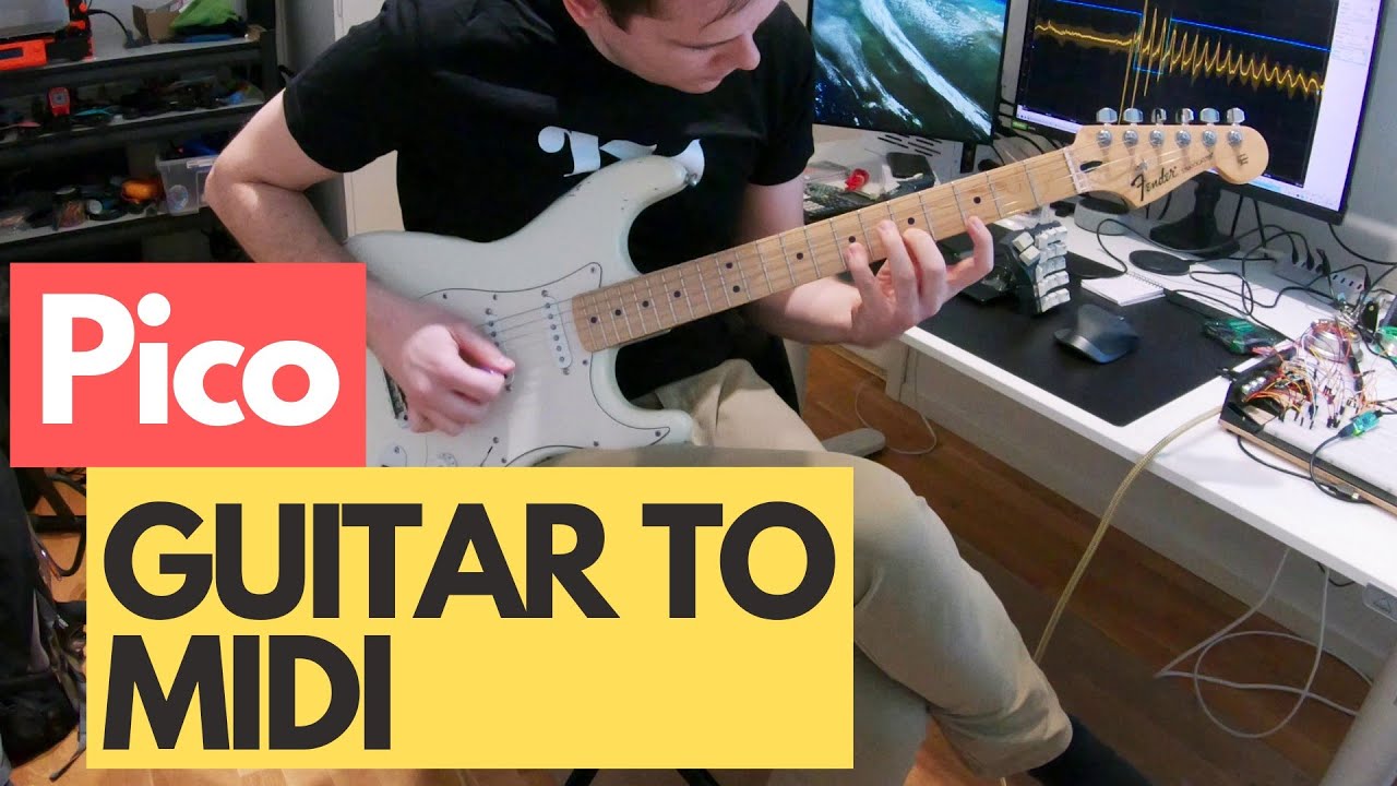
#raspberry #pi #pico #guitar #midi #guitartomidi
In this video I am demoing my Raspberry Pi Pico based Guitar To MIDI converter. I am quite blown away by the results as I would not have expected this 4$ micro controller to perform this task. The latency is lower than any other controller I have tried. If you enjoyed this video. Please leave a t...
blazing scaffold
And, is circuitpython suggested for this, or is arduino "better"?
distant spade
@blazing scaffold how does it sample audio?
blazing scaffold
Looking at the code, it does seem to use the two cores. So no cpy here.
It seems to be doing a 10khz sample by reading from the ADC directly (after amping the signal with an external opamp)
blazing scaffold
@distant spade Is there another way to sample the audio?
distant spade
we have pdmin now
which uses a pdm microphone (what we use on circuit playgrounds)
 cobalt fox
Is the RP2040's BOOTSEL button accessible by code to use as a regular button? Just curious if it could be used outside of the reset process. Please reply or @ me. Thx fellow makers!
small meteor
@cobalt fox BOOTSEL is in the schematic.
It physically interacts as CS (chip select) for QSPI flashROM.
When you hold it down, flashROM is inactive (entirely) as the chip isn't selected.
vagrant widget
so its less of a gpio button, and more of a way to make SPI access fail
cobalt fox
@small meteor so no then? no 'user' accessible buttons? maybe in the next revision.... 🙂 At least it has an onboard LED.
small meteor
No user accessible buttons - that's right.
It's a $4 board and I bet they're losing money on them.
(but your vendor is perhaps turning a profit)
cobalt fox
Where's the best place to find a "large" reference chart of all the specs of all the RP's? Looking to compare ones with onboard wifi, size, current draw, etc.
storm heath
Does this help https://www.raspberrypi.org/documentation/faqs/#hardware-compare?
Current draw is down several pages under "Power"
That is for Raspberry Pi's -- not RP2040s - not sure what you are looking for.
cobalt fox
Thx @storm heath. I'm looking for power consumptions for typical scenarios, like idle, idle w/ wifi/network/bluetooth/etc disabled, receiving/transmitting, various sleep modes, etc. I'm a noob in the MCU world and most of my experience is with Espressif/ESP32 boards.
storm heath
If you are looking for Raspberry Pi info you may get more help in #help-with-linux-sbcs -- this channel is for the RP2040
cobalt fox
Probably, I figured the RP2040 or Zero was as close to a comparison to low power consumption MCUs as I could get--at least at this point in time. I'm sure someone wrote up a table of real world power readings for them in various modes. Just need to find it, or buy them myself and find out. But would need to invest in a good low current-capable tester.
small meteor
It's not really that at all. It's learning how to use the low power modes.
Mostly a software problem.
cobalt fox
definitely that too
small meteor
Simple example: USB usually will disconnect/fail when you blindly access low power and then try to 'come back' to normal.
So if you wanted USB to work, you'd then remove the power (entirely) to cold boot again.
You could power it low/down and maybe bring it back, but you'd lose USB.
So if you wanted information back from the system, it'd have to be either preserved on-system, or transmitted 'somehow' (I'm guessing the USART won't be nearly as problematic in this regard).
These are just guesses.
storm heath
There has been a lot of recent work getting low power running with CircuitPython on the ESP32s2 boards and it is now being worked on for the nRF52840 boards.
 solar cloud
anyone have a waveshare e-paper working with the pico?
distant spade
@solar cloud you'll need to be more specific about what display it is. CircuitPython supports many e-paper displays already but not all
solar cloud
5.83inch E-Paper E-Ink Display HAT For Raspberry Pi, 648×480 Pixels, Black / White Dual-Color, SPI Interface
This one specifically
They provide a raspberry pi python example but not sure all the dependencies work
distant spade
5.83 inch high resolution 648x480, e-ink display, GDEW0583T8-Good Display
we don't have a driver for the UC8179 that I know of
very similar to the UC8176 on @silver stream's display
 silver stream
@themitch22 all waveshare 4.2 and above work with adafruit_il0398
@solar cloud my display currently isn't showing all 3 levels of black well. But I will get to it soon.
See the example 0398 which calls the above file to create the display.
silver stream
I turned rotation off to 0.
candid seal
on the feather RP2040, which GPIO pin is the built in neopixel on? I don't see it in the documentation.
storm heath
@candid seal it is on GPIO16 https://github.com/adafruit/circuitpython/blob/main/ports/raspberrypi/boards/adafruit_feather_rp2040/pins.c#L30
In CircuitPython it is board.NEOPIXEL
candid seal
storm heath
<@!248264531606765568> it is on GPIO16 <https://github.com/adafruit/circuitpytho...
ah, thank you!
charred stone
Just wrote a 4x4 keypad driver:
.side_set 4 opt

; A 4x4 keypad driver.

nop                 side 0b0001     ; Setup to read first row
.wrap_target
start:
    mov y, x                        ; Store last isr value
    in pins, 4      side 0b0010     ; Read all columns and select next row
    in pins, 4      side 0b0100     ; Read all columns and select next row
    in pins, 4      side 0b1000     ; Read all columns and select next row
    in pins, 4      side 0b0001     ; Read all columns and select next row
    in null, 16

    mov x, isr                      ; Setup for button check
    jmp !x, start                   ; If ISR is zero (no buttons pressed), jump to start
    jmp x!=y, pressed               ; If ISR is not equal to last value, jump to to push
    jmp start

pressed:
    push                            ; Push ISR
.wrap```
It will queue up to 8 presses (if the FIFOs are joined) and take care of debouncing if the clock divider is set low enoughI'm trying to re-build a RPi Pico c++ project for Feather RP2040, but I can't get it working. For now I’m just building the blink example so I’m pretty sure my code itself isn’t the issue.
I am building with cmake -D"PICO_BOARD=adafruit_feather_rp2040" ..
sorry to be a potato, but is there anything else I need to do to build for this board?
I've got the SDK updated and I see the feather rp2040 header file in the default boards directory.
When I run picotool info on the installed binary it shows up as the correct board type, but I can’t even get the blink example to flash the led on GP13
candid seal
There must be a step I'm missing in addition to the cmake build flag. When I compile blink for the default pico and load it on a RPi_pico, the built in LED blinks. If I compile for feather and load that onto the RPi Pico, it correctly blinks an LED connected to GP13 - so the board configuration is being loaded correctly in either case. But, the feather binary still doesn't do anything on the feather_rp2040
as a control, I tested that I can build circuitpython for the feather rp2040 and that loads and works fine - so I don't think it's anything to do with my cable/computer/build environment
distant spade
candid seal
There must be a step I'm missing in addition to the cmake build flag. When I com...
Try increasing the flash divisor in the board definition
PICO_FLASH_SPI_CLKDIV=6
candid seal
distant spade
Try increasing the flash divisor in the board definition
Thanks for the tip! I tried this, but it didn't help
candid seal
I noticed the board definition still has the flash chip size as 4MB and not 8. I changed it to 8, but still no dice 😦
fast perch
I have an untested idea to make pulsein less CPU intensive by doing the pulse length counting right in pio... I think that jmp pin can be used in this way. It ends up being quite a few instructions, though. ```
mov x, 0 ; could do via init
mov y, 1 ; to save instructions & allow wrap
wait_true:
; In this section, we're waiting for pin to become true
jmp x--, ignore_overflow0
ignore_overflow0:
jmp pin, became_true
jmp wait_true
became_true:
; we want to shift out the 31-bit counter + a "1" bit (from y) to indicate
; the pin became true at time 'x'
in 31, x
in 1, y
wait_false:
jmp x--, ignore_overflow1
ignore_overflow2:
jmp pin, wait_false [1] ; Delay to match timing of "wait true"
; we want to shift out the 31-bit counter + a "0" bit (from null) to
; indicate the pin became false at time 'x'
in 31, x
in 1, null
jmp wait_true               ; would be nice to .wrap
er I still have some true/false backwards in that code, oops. think it's right now
fast perch
I'm not sure CP can set the pin used by 'jmp pin'
candid seal
So first off I’ll start by promising this will be the last post I clog up this discord with on this particular issue 🙂
Also I should be up front that I just took up learning about microelectronics and programming as a hobby recently, so it is probable I do not know what I am doing or talking about 😛
That all said...
regarding my above posts about not being able to run c code on the Feather RP2040, I wonder if the issue is with the board itself? I also ordered a Sparkfun Thing Plus play with and that came today. Building my code for the Thing Plus with the correct cmake flag and it works perfectly as expected. So I’m at a loss to say why I cant get anything working on the feather (except circuitpy). I am curious if others have the same issue or if it is just me. I am aware these are very new so this is all expected. Again, not complaining here just trying to figure it out and maybe be helpful in case it isn't "just me"
small meteor
@candid seal Not sure what that would be.
The regular Pi Pico works fine with their SDK.
candid seal
me either - the regular pi pico and thing plus work fine. It's just the feather giving me issues
candid seal
other than the adafruit_feather_rp2040.h definition file I don't know what else to check
small meteor
My guess is that l.a. would not have released it without a working C/C++ SDK going.
candid seal
yeah it has 8 MB. I updated the definition header (still said 4MB) but still no dice
I built circuitpython from source and that works fine
so I'm just very confused 😛
small meteor
You can turn on all compiler warnings.
candid seal
thats a good point
small meteor
My CamelForth project has all warnings turned on.
if ( CMAKE_COMPILER_IS_GNUCC )
    set(CMAKE_CXX_FLAGS  "${CMAKE_CXX_FLAGS} -Wall -Wextra")
endif()
I acknowledge this - I assume it must be on my end, but with other boards working and apparently no issues with the board definition file I just can't think of what else could be the issue
small meteor
Maybe 'make > ./build.log 2>&1 ; date'
Then you will have a complete build log. It does expose your $HOME and related paths you own under that login, so it's prudent to search and replace those. ;)
The SDK has a 'just works' philosophy behind it, so your binaries tend to be bigger but work with less troubleshooting (I think; not really sure yet).
I drag and drop the built .UF2 directly onto the device (the drive exposed when you do the magic thing on a cold boot).
I have had good results with both no_flash and copy_to_ram.
You may want to try erasing a small block of flash to gain access to flash space.
candid seal
Thanks @small meteor I will try all those things. I am running make with the build log now (taking a lot longer than normal). Appreciate the input!!
small meteor
"We're all in this together." -Harry Tuttle
make should take the same amount of time if you redirect output to a logfile.
I throw ;date on the end of the command line but it's superfluous as it builds pretty fast. (well my application does, heh)
candid seal
I forgot to cd into build first and it was making building the whole pico-examples folder :/
small meteor
 $ cd pico-examples
 $ mkdir build
 $ cd build
 $ rm -rf ./stuff* <figure this out manually>
 $ export PICO_SDK_PATH=../../pico-sdk
 $ cmake ..
 $ cd application_dir
 $ make > ./build.log 2>&1 ; date
stuff* won't be there if mkdir build succeeds. ;)
I run a cleanup script in build so that I don't have to do anything else there (such as destroy it and create it anew).
The $PICO_SDK_PATH will persist until you close that shell, if it was export 'ed as in the above.
This all assumes Debian Linux. ;)
I think if you have an .UF2 built the compiler completed without errors (maybe warnings, but no errors).
candid seal
it compiles without errors and builds the UF2
it's just that the UF2 doesn't do anything on the feather
small meteor
So just to be very clear: make is typed under pico-examples/build/my_application as that's how things were designed.
What is it programmed to 'do'?
candid seal
and I know the definitions are imported correct bc if I install that UF2 on the standard Pico and put an LED on GPIO13, it flashes
small meteor
So yeah you may be toggling the wrong port pin.
small meteor
;)


 candid seal
small meteor
So yeah you may be toggling the wrong port pin.
candid seal
small meteor
So yeah you may be toggling the wrong port pin.
could you elaborate on this? I'm not sure what you mean
small meteor
I looked - GPIO13 seems good for the Feather RP2040.
candid seal
yeah that's where the led is
small meteor
candid seal
and...I have the blink.c set to 'DEFAULT_LED' for the LED Pin
and if I compile against the standard pico board def (led as GPIO25) it builds, compiles, and loads onto a pico and blinks the builtin led correctly
candid seal
what I mean is i'm not speifying LED pin. I'm letting the compiler pull from whatever is in the board definition
candid seal
 candid seal
small meteor
Just use `13` there instead of `LED_PIN` to force it.
candid seal
small meteor
Just use `13` there instead of `LED_PIN` to force it.
I have tried that too
candid seal
ok fair point. I have tried my own code, but only blink so far for code I know for certain doesn't have issues
I'll do printf
small meteor
printf(foo) works similar to Serial.Print(foo) in Arduinoville.
If printf() works and blink doesn't that says something.
printf() accepts format strings similar to sprintf() in Linux.
(but it doesn't always need them)
printf("Hello\n"); is valid.
candid seal
I have noticed that the feather doesn't even show up with a serial port with these binaries I've compiled
under cpy is the only place it shows up. Even though I have
small meteor
Hm.
candid seal
in my cmakelists
 small meteor
I spent a whole day getting the environment correct. Well, working .. not correct until I have more experience and could say that. ;)
That looks like it'd enable USB yep.
candid seal
small meteor
I spent a whole day getting the environment correct. Well, working .. not corre...
I even re-tried all this on a raspberrypi 4 with the environment set up by their super easy script
small meteor
I get a live /dev/ttyACM0 as usual. That's where the serial dialog happens.
candid seal
you're using a feather 2040?
small meteor
(I also enable the USART and can see messages from the Pico (using printf()) but I can't gain keystrokes via USART.
candid seal
that is really good for me to know if yours is working!! That at least confirms the issue is on my end beyond any doubt
small meteor
I don't have the Feather RP2040. I bought a Pico from Valros. Whatever (new jersey).
small meteor
Try building Camelforth. ;)
candid seal
ok
small meteor
Complete build environment there. Just add in pico-sdk
small meteor
If it works it'll print its identity when it boots.
I wouldn't change anything .. the flash issue may prevent it from completing anyway.
The pico version I wrote on the other hand might load on the Feather.
Maybe not.
Try the no_flash variant of CMakeLists.txt
That might obviate the differences.
The no_flash option forces you to upload the .UF2 every reset. ;)
(it never does reside anywhere in QSPI flash space)
small meteor
Come to think of it it'll try to use flash_range_erase(foo, bar) so you have to disable that line.
The effect of it isn't felt in CamelForth until you try to DUMP the memory.
It completes but is weird. ;) the flash_range_erase(foo, bar) wakes up QSPI flash (sets some parameter that wasn't being set)
That and the LED pin assignment is probably all the porting necessary to run on your harware (albeit missing functionality related to QSPI flashROM).
I think if you get a Forth interpreter going on your target that'll improve your understanding of how it relates to the SDK.
candid seal
still trying to figure out how to build in your directory
candid seal
small meteor
Complete build environment there. Just add in pico-sdk
ah - there's the step i'm missing
small meteor
pico-examples and pico-sdk are on the same directory level, just like with the SDK examples.
My pico-examples is an extract of theirs.
(I didn't want a ton of examples in my repo from them; I used the same structure, or something similar, anyway .. whatever satisfies cmake).
candid seal
ok I built camelforth-b...I think
first is control build - no changes to anything and loaded onto a RPi Pico, but nothing is happening
candid seal
yes
small meteor
CamelForth should blink 3 times on power on. ;)
small meteor
;) so 'it does SOMETHING' ;)
candid seal
😆 exactly
small meteor
See if you can find the serial device.
/dev/ttyACM0 in Linux. Any telecomm program should work.
candid seal
yeah Ive got the serial pport too
small meteor
Should at least echo keystrokes.
candid seal
 small meteor
That's quit a few zero's in that device name.
btw when it's working I think you can just type 'blink' and it will blink once.
blink blink blink will blink 3 times, &c.
Control J may be necessary instead of ENTER. ;)
(Control M is Carriage Return; Control J is LINEFEED).
candid seal
small meteor
btw when it's working I think you can just type 'blink' and it will blink once.
very cool - it's def working then. Booted up Adruino IDE serial monitor to send the commands and all running on the Pico alright
now I'm going to try to build for feather
small meteor
Sweet.
candid seal
should I pass the cmake build flag for the correct board, or hardcode the LED to 13 in teh source?
small meteor
I hardcoded the LED in that file I showed you to GPIO25 as I hadn't even known the Feather RP2040 existed.
So you would edit that file to say 13 not 25 unless it has both. ;)
candid seal
sweet I'll do that
small meteor
I didn't choose a board when I made this program, that I'm aware of. I copied existing work.
In general I preserved what was there in the SDK pico-examples directory .. with the exception of each of the examples, themselves. ;)
a) add my example
b) remove all of their examples
I kept their top level files intact or redacted what was obviously only there in support of their examples, that mine did not require.
candid seal
I'm first gonna try the standard default pico build (default board) with just the led pin changed
small meteor
Yeah I don't think there's two chips so some of that approach should work.
RP2040 is the MCU on both boards afaik
small meteor
QSPI flash identifies somehow back to the system, so that part should be very specific to the Adafruit board.
candid seal
there's no circuitpython build for the Sparkfun thing plus, but I just loaded the standrard pico CPY build onto it and it works 100%
for example
small meteor
I'm trying to think of how to differentiate between them. ;)
candid seal
no dice on the feather
will run cmake with -DPICO_BOARD=adafruit_feather_rp2040 now and see if it makes a difference
small meteor
;)
Where's you get that define from?
(I scanned the learn.adafruit.com on the Feather RP2040 - nothing seen wrt C/C++ at all)
candid seal
 small meteor
(they point you to the root directory of the Raspberry Pi repo for the SDK)
candid seal
small meteor
Where's you get that define from?
Appendix D in the C++ SDK
no sorry, the command is in Appendx C
the instructions for building alternate boards are in APpendix D
small meteor
;)
small meteor
Well that picotool report looks okay.
0x10000000 is QSPI flashROM space.
It seems to know you have an adafruit feather. hmm.
 small meteor
Well it is a 8 MB flash chip on the Feather.
candid seal
but I'm glad I've at least replicated my issue in an independent build environment
small meteor
I don't know where that's allocated; I assume the lowest address on that flash is still
0x10000000.
candid seal
yeah I have some feeling that the flash chip is the issue here (but again I shoudl preference that I don't know much about this stuff...)
I watched the "From the Bench" vid last night where L.A talked about this feather and mentioned that the reason it now has 8MB instead of 4MB was some issue with the flash chips...?
small meteor
If it's working you should see the three blinks from CamelForth
candid seal
I don't even get a serial port showing up
small meteor
She said it was easier to use the 8MB chip so they just went ahead and used the larger chip.
candid seal
The thing plus is 16MB and it works with the sdk examples
small meteor
The 'it works' test is very limited.
candid seal
so again, I'm just very confused. I guess the only thing to do is sit back and wait for others to either complain or not
candid seal
I'm new to programming and microcontrollers, but I do feel pretty confident I've eliminated my computer, cable, build environment from the list of sources for issue
small meteor
That CamelForth revision history is complete so you can start from an earlier version and see what changed and when.
Generally only a few lines of code are changed in any one commit, there.
candid seal
I'm going to go have a beer, but I really really appreciate you helping me look into this!
small meteor
;)
candid seal
I'll come back to it later tonight
candid seal
small meteor
;)
🙏
small meteor
take care!
small meteor
@candid seal Updated the camelforth repository for multiple targets. UNTESTED.
candid seal
Sweet, thanks for letting me know!I will test it out
small meteor
also look at my build log for the exact gcc version
the SDK seems too small to include a compiler.
@candid seal I don't remember my decision process wrt the compiler version.
-- The C compiler identification is GNU 7.3.1
-- The CXX compiler identification is GNU 7.3.1
yet:
~$   gcc --version
gcc (Debian 8.3.0-6) 8.3.0
doesn't seem to be a factor, because:
PICO compiler is pico_arm_gcc
 91 [ 32%] Performing configure step for 'ELF2UF2Build'
 92 -- The C compiler identification is GNU 8.3.0
 93 -- The CXX compiler identification is GNU 8.3.0
 $   cat -n /var/lib/dpkg/info/gcc-arm-none-eabi.list |egrep bin|egrep '\.'
     8  /usr/bin/arm-none-eabi-gcc-7.3.1
 $   cat /var/lib/dpkg/info/gcc-8.list |egrep bin |egrep 'cc\-8'|egrep -v linux
/usr/bin/gcc-8
 $   which gcc
/usr/bin/gcc
 $   ls -la /usr/bin/gcc
lrwxrwxrwx 1 root root 5 Feb 25  2019 /usr/bin/gcc -> gcc-8
So when it wants gcc it uses version 8.3.0.
When it wants arm-none-eabi-gcc it uses version 7.3.1.
Both are stock debian packages - almost definitely. When I download the eabi from the vendor, it goes in ~/dev and root isn't used to 'install' it.
The one in ~/dev is the one I use to build CircuitPython.
candid seal
I watched a deep dive that @distant spade did last week and it’s got me thinking the issue could be the flash configuration - which I think he may have been alluding to in his earlier reply to me.
small meteor
So you have to say something special for Feather RP2040 to make it go?
candid seal
I’ve spent hours trying to debug this issue - now I’m just waiting for someone else with an 8MB feather to tell me if they can build their own C code without doing fancy flash configuration.
candid seal
Sounds like Scott had to do some custom configuration of the flash boot process to get CPY to run
small meteor
I don't know. It just doesn't seem that likely that it's them and not you. ;)
Did you read all the issues in the repository?
candid seal
Yeah I still acknowledge this
small meteor
(I'm guessing that'd mean, perforce, you read the raspberrypi github not the adafruit github for those issues with the SDK).
Within a week or two if there's documentation to happen on the learn.adafruit.com site that hasn't happened yet, it'll probably be there.
candid seal
There’s not many other boards out yet
small meteor
nobody has chips
candid seal
It’s just so new.
small meteor
They have designs and advertisements
I had to go to the New Jersey vendor to get one RPi Pico RP2040.
I didn't blow it up and it 'works' so I'm happy with it.
candid seal
I live like 30 miles outside NYC so even among the people that ordered I think I got it relatively early.
small meteor
What night were the Feather RP2040's in stock, anyway?
candid seal
I’m not sure if there were multiple batches or not. I got an email notification in the afternoon early last week and they shipped next day. Came a day after that since I’m close
small meteor
Yeah I'm in Connecticut so if I order on Thursday before 11 a.m. I get it Friday morning.
Alright well if you want to talk further catch me in #general-chat as my byline is excessive in this chan for one subject. ;)
candid seal
Thanks for all your help! And yes I’ll take this to the off topic channel - much appreciated!
small meteor
;)
 full oak
Has anyone found a way to do Frequency Shift Keying or Phase shift Keying or Amplitude shift keying on the Raspberry Pi Pico ?
Ideally I’d like to use ASK as I already have some Ardunio s using 433 MHz for communication between each other
 small meteor
I don't see how configurable GPIO gives you those keying methods. ;)
PSK in particular seems a candidate for analog techiques.
I guess we'll see examples soon enough if it's feasible to do them.
(I always assumed an external chip would be required for any comms other than those built in).
full oak
Ohhhh .. I was hoping there was a equivalent to Ardunio airspace RadioHead RH_ASK Library
small meteor
I haven't really heard detailed protocol discussions here.
Digital kind of came and went in Ham Radio a while ago.
But I would still comb articles in ham magazines since if they do them they're going to want to publish about them.
(all those you mentioned I've heard about in a ham radio context, including but not limited to packet radio).
full oak
Alright.. Ill hold experimenting for now.. it was more of a tinkering around than a must complete project
small meteor
Don't let me discourage you .. I'm just making guesses.
It just sounds too involved for what the pio seems to be about.
full oak
But these 433mhz modules are pretty cool.. like $3 for A transmitter and receiver... far cheaper than say LoRa or RFM69 models
small meteor
There are a few people using this channel who have done significant pio programming (I haven't).
433 MHz 'module' could be anything.
My guess is the LoRa stuff is cheap enough for what it is delivering.
full oak
Ohh .. well more specificity these chips

eBay
433Mhz Wireless RF Transmitter + Receiver Module (Pair). 1 X Regeneration Wireless Transmitter Module. Transmitter Speed: 4 KB/S. Transmitter Power: 10 mW. 1 X Receiver Module. Model: MX-FS-03V. Attenna: 25 cm Single core wire or multi-core wire.
small meteor
Do you have a proper vendor and datasheet on that?
I don't even access anything on that ebay.com domain. ;)
full oak
I have only followed the “dronebot workshop” guide made for Ardunio
 acoustic beacon
can anyone point me to a pio example setting up a number of consecutive input pins? i’d like to try reading a parallel data bus. something using micropython would be good, or C. i’ve looked through all the examples i can find, but they tend to deal mostly with serial or led strings. thanks!
 olive forum
hey folks, I don't know if this makes any sense, but I'm trying to convert some pioasm to adafruit_pioasm and I found these lines don't work:
    set x, 0
    mov pins, !x
I am not sure if that is enough to go on - I know that https://learn.adafruit.com/intro-to-rp2040-pio-with-circuitpython lists one of the differences as "mov operator restrictions" but I can't find the elaboration of that - does anyone have anything that might help me?
solar cloud
anyone have an EasyEDA symbol/footprint for the pico?
distant spade
olive forum
hey folks, I don't know if this makes any sense, but I'm trying to convert some ...
I don't think it supports !x yet
need to add it here: https://github.com/adafruit/Adafruit_CircuitPython_PIOASM/blob/main/adafruit_pioasm.py#L141-L147
GitHub
Simple assembler to convert pioasm to bytes. Contribute to adafruit/Adafruit_CircuitPython_PIOASM development by creating an account on GitHub.
olive forum
distant spade
need to add it here: https://github.com/adafruit/Adafruit_CircuitPython_PIOASM/b...
Thanks, yeah I am currently looking for the alternative. My SO question is here: https://raspberrypi.stackexchange.com/questions/122307/pico-asm-conversion-between-pioasm-and-adafruit-pioasm-mov-command

Raspberry Pi Stack Exchange
I am running CircuitPython on a Raspberry Pi Pico and I am attempting to do some pioasm, which is different on CircuitPython than in MicroPython.
According to the adafruit pioasm documentation:
Ma...
distant spade
olive forum
Thanks, yeah I am currently looking for the alternative. My SO question is here:...
I'd suggest filing an issue on the library. It shouldn't be hard to implement
 ebon lily
does pio allow to set, say, sort of "events" or something?
https://mauser.pt/catalog/product_info.php?cPath=1667_2604_2682&products_id=096-7627 <-- i bought one of this, and wanted to do something when one button is detected to be pressed

Esta placa é um teclado de 16 botões que estão dispostos em uma matriz 4 x 4. Em 4 linhas há 4 colunas ligadas, razão pela qual apenas 8 linhas de E / S são necessárias.
- CARACTERÍSTICAS ESPECIAIS: Vincula quatro linhas a quatro colunas e requer apenas 8 linhas de E / S
- DIMENSÕES: 39 x 43 x 7 mm
- PESO: 12 g
so, i was thinking about letting pio handle this and then interrupt the python to say that this button was pressed
i have absolutely no idea if this is possible at all or not
small meteor
@ebon lily I think I saw it said somewhere that Micropython has some interrupt handling.
small meteor
If it's done in CircuitPython not all that much will be RP2040 specific, would be my guess.
CircuitPython tends towards a consistent interface across platforms.
 crude locust
Just found this resource of PIO examples for the Pico
https://github.com/raspberrypi/pico-examples/tree/master/pio
GitHub
Contribute to raspberrypi/pico-examples development by creating an account on GitHub.
neon dock
crude locust
Just found this resource of PIO examples for the Pico
https://github.com/raspber...
You can also check out the examples folder for the "Adafruit_CircuitPython_PIOASM" library on GitHub: https://github.com/adafruit/Adafruit_CircuitPython_PIOASM
GitHub
Simple assembler to convert pioasm to bytes. Contribute to adafruit/Adafruit_CircuitPython_PIOASM development by creating an account on GitHub.
ebon lily
🤔 so, i will probably have to use all 8 pios?
im reading it and my head is just going "nope nope nope nope"
it feels like i want to put a square into a triangle
 modern anchor
anybody know what GPIO the bootsel button is on the pico
ebon lily
i am 99% sure it isn't accessible at all
modern anchor
really it is on the pimoroni tiny 2040
ebon lily
the documentation doesn't give it any gpio pin number, only for the led
modern anchor
got it
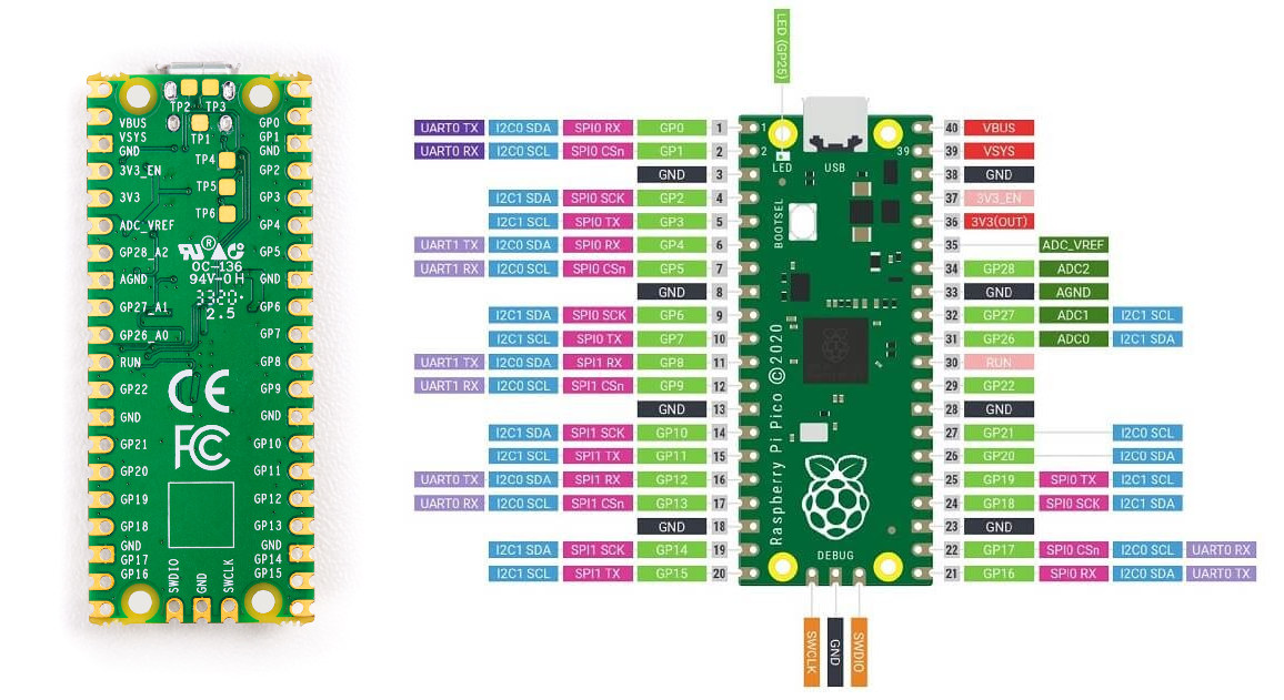
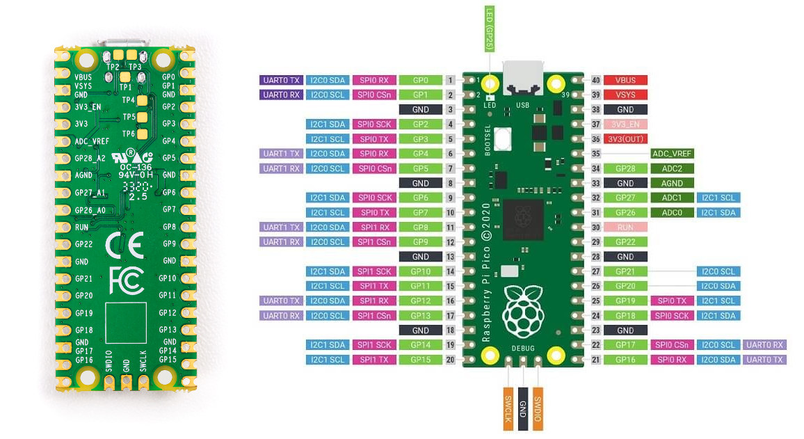 modern anchor
yah just assumed it would cause of the pimoroni board
ebon lily
i doubt you can do anything, even with pio (it seems pio is super low in the hardware level)
small meteor
@modern anchor BOOTSEL is a physical CS (or /CS) line to QSPI flashROM.
ebon lily
possibly, to give access to it over gpio
modern anchor

i think you can
but it lost in the github LMAO how do i find it now
oh yah its c not on circuitpython so pio i guess
ebon lily
GitHub
Contribute to raspberrypi/pico-examples development by creating an account on GitHub.
yeah, it's hacky at best, and seems to require disabling the flash
where the code.py is
so, even pio probably can't do anything
modern anchor
yah i got 180 buttons shipping from china, just used all my pushbuttons making this https://github.com/ArielWolle/PI-Pico-Touchscreen

GitHub
Contribute to ArielWolle/PI-Pico-Touchscreen development by creating an account on GitHub.
ebon lily
that looks interesting
modern anchor
thx
full oak
More of an Ardunio guy ... if I have a Raspberry Pi Pico and want to turn something on every day for about a minute.. what “sleep” code should I use ? Just a very large number or would it be best to do a “for i” loop for minute x total minutes
I don’t care if time “drifts”
It wouldn’t have a RTC attached
Something like sleep for 23.9 hours and a short on time
Basically I didn’t know if there is a “max sleep” time?
- ***and on for a short time
small meteor
4.1.19 hardware_rtc on p. 164 of the SDK manual
Wants to trade in year month day day-of-week hour minute second.
• void rtc_set_alarm (datetime_t *t, rtc_callback_t user_callback)
 drowsy cave
Hi everyone. I've been trying to get Audio working on the Pico. I've tried https://github.com/adafruit/Adafruit_CircuitPython_PIOASM/blob/main/examples/pioasm_i2sout.py
GitHub
Simple assembler to convert pioasm to bytes. Contribute to adafruit/Adafruit_CircuitPython_PIOASM development by creating an account on GitHub.
But I'm getting
Traceback (most recent call last):
File "code.py", line 40, in <module>
File "adafruit_pioasm.py", line 65, in assemble
IndexError: list index out of range
Any idea if it's me doing something wrong, or if it's the code?
Line 40 is assembled = adafruit_pioasm.assemble(program)
drowsy cave
Ignore me! It's compiling now that I've updated the UF2 and the pioasm library
No output, but hey.
Ah. Output. Yes, that's fairly horrible.
small meteor
@drowsy cave #help-with-circuitpython The system is portable to other platforms.
(Same dev team does all the ports)
small meteor
@drowsy cave Fair enough, but still circuitpython people are more likely to know.
You could ask here and just drop a notice, there, saying it's here. I don't know how many visit both.
Also the error looks superficially more like a problem with python (any python) than something specific to hardware.
drowsy cave
That's fine. Got it working - I needed to grab the latest UF2 and ASM library.
small meteor
@drowsy cave I was going to go for 'do you have newlines for line endings' as the parser seems cued to newlines (rather than carriage returns).
drowsy cave
Interesting... It does compile now, though. It just sounds blummin' awful!
small meteor
lol
It's a demo - if you put it on a scope that'd be interesting to see.
Maybe 'integrate' (if that's the word) using a capacitor.
@candid seal Got a Feather RP2040 on order.
Will find out mid-week where things stand.
Can't imagine having an issue, though. ;)
git remote update ; git pull ; # /done_deal
candid seal
@small meteor awesome!
small meteor
zoom.
I only got one for testing; the one I have already is sufficient for my uses.
candid seal
Definitely let me know the outcome please 🙏
I summarized my issue in the support forum thread.
I just tried it again after days with a fresh clone of the pico repos. I can build blink for RPi Pico, and I can build blink for the Sparkfun Thing Plus RP2040. The respective compiled binaries run on each
I can build blink for the Feather RP2040 too, but it still doesn’t do anything - I am admittedly not an expert in this, but it is hard for me to believe the problem is with my end given 2 out of 3 boards work as expected. So, very interested to hear reports from others 🙂
small meteor
Maybe you just haven't made a big enough mistake with regard to belief, yet, to know. ;)
Meanwhile you can start your github repository of your problem code.
Though it looks like you stuck to blink (factory demo) so that should be factored out. ;)
I have all the warnings turned on.
cmake is a big puzzle to me; I spent an entire day getting it to work 'correctly'.