#help-with-rp2040-pio
1 messages · Page 1 of 1 (latest)
 lucid garnet
On-chip programmable LDO to generate core voltage" Does this allow me to run the pico at 2.75v or maybe communicate with an analog 2.75v device? If not, what does this feature do?
Ah, so you can do 1.8v logic with it
Dunno how I'd make it use of that 😅
 distant spade
check the datasheet though. I haven't thought about non-3.3v voltages
lucid garnet
I was hoping I could talk to a coin cell operated device that seems to be running 2.75v logic
distant spade
I'm not sure 🙂
distant spade
np, will have another on friday 🙂
lucid garnet
Great!
distant spade
I enjoy it
lucid garnet
Everything that happens at adafruit exposes so many details about things that would otherwise be so esoteric ^_^
distant spade
ya, I love to be able to work in the open
the month I was secretly working on the rp2040 was weird
lucid garnet
I bet. Secret early access but not many people to geek out with about it
distant spade
yup yup
lucid garnet
Can't wait for the learn articles on the pio. Still trying to wrap my head around everything to do with it
distant spade
and having to make sure I don't leak it 🙂
I think we'll be fully learning the PIO over the next few years
it's all early days
lucid garnet
distant spade
and having to make sure I don't leak it 🙂
Random windows or history, ya
lucid garnet
distant spade
I think we'll be fully learning the PIO over the next few years
The bringer of light, you will be
distant spade
🙂 I like geeking out on it
 frank quail
I remember there was talk recently about the MPY port to ESP32S2 and you said something like Damien couldn't work on it because he had to prioritize what he was contracted for or something
distant spade
😄
frank quail
turns out is was the RPF !
lucid garnet
I came from software and game programming but never really was that great. But EE on the other hand- reading data sheets and making schematics - it's all there in the docs it's like a puzzle piecing it all together. I'm finding circuits are a much bigger draw to me.
distant spade
ya, I'm mostly software trained too. after all of my esp32-s2 work the closed system of the rp2040 is nice
lucid garnet
Really happy for the pico and circuit python. I kind loath c in arduino. Python flows like butter
distant spade
great! had you heard of circuitpython before?
lucid garnet
I had always heard of it when tinkering with arduino and doing adafruit stuff but never got a board and started to play with it until now with the pico
I'm very happy to do micro stuff with python.
distant spade
kk. I was curious since micropython is officially supported and promoted
lucid garnet
Ya, is that going to have the most support for a while now or is circuit python going to be fleshed out for it right away?
lucid garnet
Cool. I figured it start down the road of CP and if there's any gaps I need to fill I'd look into MP
distant spade
you can always help add things to CP too 😉
lucid garnet
Def
I'm trying to get my nokia 5110 screen working on it now, but the init sequences aren't set up in CP like many other screens.
For displayio at least to use with the stage and game and bmp stuff
distant spade
ugame is a built in module too
lucid garnet
I have just draw pixel and text support from the ada lib otherwise
I didn't delve too deep, but one of the basic learns for the pygamer stuff didn't run on my pico because ugame wasn't found or something
distant spade
you can probably enable it easily
lucid garnet
No module named ugame it said
distant spade
you have to enable it in the build
distant spade

Adafruit Learning System
How to build CircuitPython yourself on different platforms
distant spade
yup, to use ugame on it
lucid garnet
Ok cool tyvm that was the key
Do you have a lead on how I could go about initializing the nokia 5110 so that I can use it with the displayio stuff?
It needs an INIT_SEQUENCE
Trying to make an old school virtual pet and need an old tyme screen lol
distant spade
I've never looked at the 5110 unfortunately
@minor parcel would know (author of ugame)
lucid garnet
So far I can do it with adafruit_pcd8544 but that screen isn't part of the game lib init sequence options and adafruit_pcd8544 doesn't have an easy way to handle graphics
distant spade
right
lucid garnet
So I converted all my pixels to a list and drew each one individually 😅
But that probably won't work well when trying to animate and such
 minor parcel
you can copy the init sequence from any library for that display
minor parcel
in practice you can use the defaults, just send the display on command
lucid garnet
minor parcel
you can copy the init sequence from any library for that display
thanks! I'm looking through https://github.com/adafruit/Adafruit-PCD8544-Nokia-5110-LCD-library/blob/cc8e97fc9bb0274a1dbd4efaff21537a88f17a39/Adafruit_PCD8544.cpp but I'm not sure how to spot the init sequence. I don't see anything that looks similar to the init sequences used for other displays

GitHub
Arduino driver for PC8544, most commonly found in small Nokia 5110's - adafruit/Adafruit-PCD8544-Nokia-5110-LCD-library
  @brief Initialize the display. Set bias and contrast, enter normal mode.
 */
void Adafruit_PCD8544::initDisplay() {

  // toggle RST low to reset
  if (_rst > 0) {
    digitalWrite(_rst, LOW);
    delay(500);
    digitalWrite(_rst, HIGH);
  }

  setBias(_bias);
  setContrast(_contrast);

  // normal mode
  command(PCD8544_FUNCTIONSET);

  // Set display to Normal
  command(PCD8544_DISPLAYCONTROL | PCD8544_DISPLAYNORMAL);
}``` I'm guessing this is the init sequence from that lib, but I'm unsure how to translate that to the byte sequence the other displays use as their INIT_SEQUENCE paramthis convo forked from other PIO conversations, so perhaps we can follow up in #help-with-circuitpython
minor parcel
you only really need the last one, command(PCD8544_DISPLAYCONTROL | PCD8544_DISPLAYNORMAL);
those two constants are numbers
you will find them in the .h files
lucid garnet
yep, i found them there
minor parcel
so basically you just need to send that one byte to switch the display on with all the defaults
lucid garnet
  0x08 ///< Basic instruction set - Set display configuration```

```#define PCD8544_DISPLAYNORMAL 0x4 ///< Display control, normal mode```you might need to adjust bias and contrast for your particular screen, the commands for that will be in those setBias and setContrast functions
lucid garnet
I'm unfamiliar with working with byte sequences. Would that be b"\x08\x4" as in ```display = displayio.Display(display_bus, b"\x08\x4", width=84, height=48, backlight_pin=board.GP18)
no, because they OR them together
lucid garnet
oh, right
minor parcel
command(PCD8544_DISPLAYCONTROL | PCD8544_DISPLAYNORMAL); would be b"\x0c\x00" I think, because you also need to specify the parameter count
lucid garnet
ok ty.
lucid garnet
minor parcel
you might need to adjust bias and contrast for your particular screen, the comma...
which object has these functions? The displayIO object?
minor parcel
GitHub
Arduino driver for PC8544, most commonly found in small Nokia 5110's - adafruit/Adafruit-PCD8544-Nokia-5110-LCD-library
GitHub
Arduino driver for PC8544, most commonly found in small Nokia 5110's - adafruit/Adafruit-PCD8544-Nokia-5110-LCD-library
you would just look at what whose functions do, and add appropriate bytes to the initialization for displayio
each of them sends 3 bytes
lucid garnet
oic, i thought you were referencing a setBias function in displayio that I'd need to call. I'll look to see what byte sequences were used in the original library and see how to add those to the byte sequence for initialization
minor parcel
you can also refer to the datasheet to see how those registers are to be used
lucid garnet
ok thanks. can I ask how you OR'd those to bytes together last time so I can try to do that now that I need to for these other bytes please?
lucid garnet
ok, hex is what i was lookin for. tyvm. processing...
ok, i found the byte commands and documented them here
bias
  command(PCD8544_FUNCTIONSET[0x20] | PCD8544_EXTENDEDINSTRUCTION [0x01] );
  command(PCD8544_SETBIAS [0x10]| val [5]);
  command(PCD8544_FUNCTIONSET[0x20]);


contrast
  command(PCD8544_FUNCTIONSET[0x20] | PCD8544_EXTENDEDINSTRUCTION[0x01]);
  command(PCD8544_SETVOP [0x80]| val[50]);
command(PCD8544_FUNCTIONSET[0x20]);```and am assembling the final commands ORd together here ``` #normal mode
b"\0x20" #one command
#set normal mode
b"\x0c\x00" #two commands
#bias
b"\0x21\x00" #two commands
b"\x15\x00" #two commands
b"\0x20" #one command? need to tell it one though...
#contrast
b"\0x21\x00" #two commands
b"\0xb2\x00" #two commands
b"\0x20" #one command? need to tell it one though...
but I'm missing the knowledge of how to specify that there's one command I believe
for the last of three for bias and contrast
minor parcel
I think you want the normal mode at the end
minor parcel
and you want \x00 after that \x20 too
lucid garnet
Ok. I thought x00 told it that there was two commands?
minor parcel
it tells it there are no parameters
minor parcel
other displays take a command (with DC set) and then parameters (with DC unset)
lucid garnet
Ok
minor parcel
this display wants everything as commands
minor parcel
I don't see any delays in that Arduino library
lucid garnet
Ok cool. Phew, thanks for the detailed walk through. This is stretching my skillset
minor parcel
there is only a delay for the reset pin
lucid garnet
I have to break now but will attempt to call those init byte sequences shortly
lucid garnet
minor parcel
there is only a delay for the reset pin
Ok. And that's accounted for elsewhere already or needs to be specified in my byte commands now?
minor parcel
did you even provide a reset pin?
lucid garnet
display_bus = displayio.FourWire(spi, command=board.GP21, chip_select=board.GP20, reset=board.GP19)
display = displayio.Display(display_bus, b"\x0c\x00", width=84, height=48, backlight_pin=board.GP18)
yep
lucid garnet
am I concatting these properly to send as the init_sequence param? ```display = displayio.Display(display_bus, b"\0x21\x00" b"\x15\x00" b"\0x20\x00" b"\0x21\x00"b"\0xb2\x00" b"\0x20\x00" b"\0x20\x00" b"\x0c\x00" , width=84, height=48, backlight_pin=board.GP18)
Adafruit_CircuitPython_ILI9341 had them all on new lines
minor parcel
in Python "abc" "def" is the same as "abcdef"
you can just split it onto separate lines for clarity
lucid garnet
ok
minor parcel
but you can also just have it a single string
easier to put comments when they are split
lucid garnet
#bias
b"\0x21\x00"
b"\x15\x00"
b"\0x20\x00"
#contrast
b"\0x21\x00"
b"\0xb2\x00"
b"\0x20\x00"
#normal mode
b"\0x20\x00"
#set normal mode
b"\x0c\x00"
#bias

spi = busio.SPI(board.GP10, MOSI=board.GP11)
display_bus = displayio.FourWire(spi, command=board.GP21, chip_select=board.GP20, reset=board.GP19)
display = displayio.Display(display_bus, INIT_SQEQUENCE , width=84, height=48, backlight_pin=board.GP18,backlight_on_high = False)
you will need to put that in parens if you want to write it that way
as in INIT_SEQENCE = ( ...
I also think you have to specify color_depth
and bytes_per_cell
lucid garnet
Ok ty again. I'll tackle this next step after lunch!
minor parcel
best look at some of the b&w oled displays and see how they do it
lucid garnet
to see how adafruit implemented their INIT SEQUENCES?
minor parcel
to see how the other parameters need to be specified for a 1-bit display
because I think it defaults to 16-bit color
lucid garnet
Oh ya, there's a grayscale param you can set when you make the displayio.Display object
I'm guessing that accomplishes what you're referring to
 wanton pewter
Basic question while I wait for the mailman, is the onboard temperature sensor meant to measure the temp of the rp2040 chip or of the environment? Has anyone tested readings from it and compared with external readings to see how accurate it is?
distant spade
@wanton pewter the chip itself
an off-pcb temp sensor will be better for measuring the environment
wanton pewter
@distant spade thanks, good to know and will consider off-pcb. Maybe I'll play around with getting a reading off the CPU ASAP and doing some measurements to see how much it differs from the off-pcb.
distant spade
I tested it with circuitpython so I know it works
I didn't compare with another reading though. just saw it was in an expected range
 hollow shoal
how do you 'upload' your micropython scripts to the pico? I can connect with REPL
distant spade
@hollow shoal it's easier with circuitpython. MicroPython requires thonny
this covers micropython: https://datasheets.raspberrypi.org/pico/sdk/pico_python_sdk.pdf
CircuitPython instructions are here: https://learn.adafruit.com/getting-started-with-raspberry-pi-pico-circuitpython

Adafruit Learning System
CircuitPython for Pico will get you started in minutes!
 orchid cairn
I may have done something bad to my new pico 🙂 The drive is showing as full with no extra files on the device. I tried re-loading circuit python (the release and most recent) and micropython and a uf2 blink and storage.erase_filesystem(). I get a REPL but I'm not sure what to try next.
brett@panini:/media/brett/CIRCUITPY$ df -h /media/brett/CIRCUITPY/
Filesystem Size Used Avail Use% Mounted on
/dev/sdb1 1004K 1001K 3.0K 100% /media/brett/CIRCUITPY
brett@panini:/media/brett/CIRCUITPY$ ls -la /media/brett/CIRCUITPY/
total 21
drwxr-xr-x 3 brett brett 16384 Dec 31 1969 .
drwxr-x---+ 3 root root 4096 Jan 25 19:13 ..
-rw-r--r-- 1 brett brett 95 Sep 1 2016 boot_out.txt
drwxr-xr-x 2 brett brett 512 Sep 1 2016 .fseventsd
-rw-r--r-- 1 brett brett 0 Sep 1 2016 .metadata_never_index
orchid cairn
I can and it does run. If I add a print("Hello World!") I see the message in the serial terminal
@distant spade Also Thanks! 🙂
orchid cairn
So now with a 22 byte code.py and 82 byte boot_out.txt the drive shows 1001K in use:
brett@panini:/media/brett/CIRCUITPY$ ls -la /media/brett/CIRCUITPY/
total 21
drwxr-xr-x 2 brett brett 16384 Dec 31 1969 .
drwxr-x---+ 3 root root 4096 Jan 25 19:20 ..
-rw-r--r-- 1 brett brett 82 Sep 1 2016 boot_out.txt
-rw-r--r-- 1 brett brett 22 Jan 25 19:21 code.py
brett@panini:/media/brett/CIRCUITPY$ df -h /media/brett/CIRCUITPY/
Filesystem Size Used Avail Use% Mounted on
/dev/sdc1 1004K 1001K 3.0K 100% /media/brett/CIRCUITPY
distant spade
weird!
hollow shoal
@distant spade Thanks for the help! I was scratching my head with the raspi documentation trying to figure it out w/o thonny. Didn't think to check for a circuit python port. ❤️
orchid cairn
I tried storage.erase_filesystem() in the repl which causes a reset, the board doesn't auto-remount and if I unplug and plug it in I still see code.py 😕
orchid cairn
@distant spade I do see code.py after the erase, I edited it to say 'Hola' instead and it stays the same after the erase. Yes I'm running 6.2.0-beta.0. I tried the most recent one on S3 but did not try erase_filesystem on that. I will try that now
distant spade
right, the erase will recreate it
was the filesystem full after the erase? what host OS are you on?
orchid cairn
@distant spade I just tried loading the most recent one on S3 and it behaves the same. After erase I see the
brett@panini:/media/brett$ ls -la /media/brett/CIRCUITPY/
total 21
drwxr-xr-x 2 brett brett 16384 Dec 31 1969 .
drwxr-x---+ 3 root root 4096 Jan 25 19:40 ..
-rw-r--r-- 1 brett brett 96 Sep 1 2016 boot_out.txt
-rw-r--r-- 1 brett brett 15 Jan 25 19:29 code.py
-rw-r--r-- 1 brett brett 0 Jan 25 19:29 .code.py.swp
brett@panini:/media/brett$ cat /media/brett/CIRCUITPY/code.py
print("Hola!")
brett@panini:/media/brett$ df -h /media/brett/CIRCUITPY/
Filesystem Size Used Avail Use% Mounted on
/dev/sdb1 1004K 1001K 3.0K 100% /media/brett/CIRCUITPY
Sorry, partial message, I still see the same full drive
distant spade
weird! what os?
orchid cairn
I'm on Ubuntu 20.04.1 LTS
distant spade
I'm on arch
df -h /run/media/tannewt/CIRCUITPY/
Filesystem      Size  Used Avail Use% Mounted on
/dev/sdb1      1004K  2.0K 1002K   1% /run/media/tannewt/CIRCUITPY
I also tested it on a windows computer and the drive shows full there. I reloaded the beta on that machine and the drive still showed full
distant spade
please file an issue I know some other devs run ubuntu and can try and repro
orchid cairn
Sounds good. On the adafruit/circuitpython github?
distant spade
yes please
orchid cairn
@distant spade Thanks! I'll open an issue.
distant spade
it's a weird issue. I haven't seen that before
 fair pagoda
Can CP read the onboard temperature sensor? MicroPython has it on machine.ADC4. I'm using CircuitPython 6.2.0-beta.0 on 2021-01-22.
fair pagoda
Tricky. I read that via analogio?
distant spade
nope, just read that attribute
import microcontroller
print(microcontroller.cpu[0].temperature)
Thanks. 20.0114 C if you want to know. 🙂
distant spade
🎉 🌡️
fair pagoda
I'll have to hook up the barometer and impress you with 865 kPa. Life at 1445m...
distant spade
🙂
 charred stone
Which pin group does the wait command use?
distant spade
looks
@charred stone looks like input when source is "pin"
and with "gpio" it is direct
hollow shoal
I can't seem to get circuit python working, or I am just having a brain fart and have forgotten something. Using the examples on this page https://circuitpython.readthedocs.io/en/6.0.x/shared-bindings/digitalio/index.html#digitalio.DigitalInOut
gives me the following error
Traceback (most recent call last):
File "code.py", line 4, in <module>
NameError: name 'D13' is not defined
charred stone
I set first_in_pin and in_pin_count, but it is still giving me ValueError: Instruction 1 uses extra pin for the wait command
charred stone
Okay, I'll dig into that. Thanks
distant spade

GitHub
CircuitPython - a Python implementation for teaching coding with microcontrollers - adafruit/circuitpython
 muted shoal
would an rj45->microb+PoE(or is poe not needed due to the low voltage requirements for the rp2040?) theoretically allow direct network connection? or would it require some bit of programming to properly interpret this signal
distant spade
you'd need a lot of work to talk to the network
though maybe usb host can do network
muted shoal
ah
distant spade
usually networking on a micro uses a wiznet chip: https://learn.adafruit.com/ethernet-for-circuitpython

Adafruit Learning System
Add Ethernet Connectivity to your CircuitPython Project
you can also use a wifi coprocessor
muted shoal
alrighty
charred stone
I added a print to confirm the assembler is using a wait source of 1 but Instruction 1 uses extra pin should only result from a source of 0.
distant spade
my logic must be wrong
or it's from somewhere else
what is your pioasm?
pioasm library is here too: https://github.com/adafruit/Adafruit_CircuitPython_PIOASM/blob/main/adafruit_pioasm.py
GitHub
Simple assembler to convert pioasm to bytes. Contribute to adafruit/Adafruit_CircuitPython_PIOASM development by creating an account on GitHub.
charred stone
I could have sworn that's what I used, but I copied and pasted that and it's working now
distant spade
😄 great!
@charred stone you might beat me to hooking up readinto and writeto_readinto (or whatever it's called)
charred stone
Never mind, still not working. I'll dig into it more tomorrow.
distant spade
👍
charred stone
My code is shiftreg = """ .program shiftreg .wrap_target out pins 1 wait 1 pin 0 .wrap """ if you want to try it, I'm trying to emulate a shift register
distant spade
did you verify the encoding is correct?
charred stone
I just tried (0x2090 & 0x0060) >> 5 and got 0, so that might be it. 0x2090 was printed after the wait command by assemble
orchid cairn
@distant spade I had some success! (will post this to the issue as well) I ran the 'nuke' example from the pico sdk (which 'Obliterate the contents of flash'). Now the drive shows as only 2K used. Thanks for all your hard work on this and the live streams and everything!
distant spade
@charred stone looks like the assembler is wrong
GitHub
Simple assembler to convert pioasm to bytes. Contribute to adafruit/Adafruit_CircuitPython_PIOASM development by creating an account on GitHub.
needs to shift 5 not 4
charred stone
That works, thanks
distant spade
want to do a PR?
charred stone
Sure, do you have a PR template?
distant spade
nope, just instructions: https://learn.adafruit.com/contribute-to-circuitpython-with-git-and-github

Adafruit Learning System
From fork to merge, this guide covers all the steps necessary for a successful Git and GitHub workflow.
charred stone
Thanks. Looks like the online editor will do all that for me
distant spade
yup!
charred stone
Should be good
 fast perch
a question for those who have learned a bit of PIO already -- is it plausible to use it to drive a group of segmented LED displays like these (say 4 or 8 digits total)? https://www.adafruit.com/product/1907

Display, elegantly, 012345678 or 9! Gaze, hypnotized, at ABCDEFGHIJKLM - well it can display the whole alphabet. You get the point. This is a nice, bright 14-segment alphanumeric display ...
muted shoal
how would one go about, if even possible, integrating an esp8266(one of the small ones) in with a pico to enable wireless capability
one of these
not the larger ones sadly as I dont have any of the larger ones lying around
fast perch
This guide is marked as outdated but talks about how to use esp8266 as a wifi coprocessor -- I haven't tried it personally @muted shoal https://learn.adafruit.com/adding-a-wifi-co-processor-to-circuitpython-esp8266-esp32/firmware-files
 fast perch
good luck! You're not alone in missing wifi on this thing
wanton pewter
I bought a few Picos to play with and wanted to get started with CP and the bare board before adding external sensors / buttons. So here's a minimal code.py that reads the temperature off the CPU and displays it in morse code on the LED: https://gist.github.com/jay0lee/e3cec7b2d126e3887c5c899635aeef90
 distant spade
@fast perch I'm not sure if you could easily do that display. there isn't a mechanic to decode characters to signals within PIO
fast perch
Can I put in ram [lit segments of character 0], [lit segments of character 1], ... [lit segments of character N], then have PIO "scan it out" at a high speed, though?
distant spade
yup!
fast perch
can it loop over the N pieces of data endlessly?
distant spade
if you are shifting out each byte basically
I think the DMA can
it's not really a PIO function. it just spits out what is in its fifo
(this is why I was thinking about an async PIO api)
fast perch
I decided to pick some up, it would be nice to get the to run with pio and if it doesn't work it'd be a good learning experience
@distant spade can CP do that kind of dma-looping yet or is its API "one and done" like you need for neopixels?
distant spade
we don't have an api for looping yet
right now we only have writing
though under the hood it's a transfer method
here was my brainstorm for an api: https://gist.github.com/tannewt/ecaed6ccb215a940f1b061763ef3737a
For CircuitPython help see #help-with-circuitpython. This channel is for RP2040 specific features like the PIO.
distant spade
distant spade
For CircuitPython help see <#537365702651150357>. This channel is for RP2040 spe...
hollow shoal
does circuit python support the extra thread/core on the Pico?
orchid cairn
I'm trying to look into using irqs with the pio. I think I understand how to set/clear/wait them on in pio assembly but am struggling to find how to interact with them from the circuitpython side of things. Are there any examples or leads or is this not yet supported?
@hollow shoal I can't provide an authoritative answer but based on the livestream (can be found on adafruit youtube) last Friday there isn't yet support in CP. Some discussions were using it somewhat like the PIO statemachines instead of replicating the _thread interface in micropython
hollow shoal
Thanks for the info braingram! I'm quite far off from ever using the _thread stuff, but it was neat to read about. I'm sure CP will get it implemented before I even need it!
distant spade
orchid cairn
I'm trying to look into using irqs with the pio. I think I understand how to set...
I haven't added this yet. what are you trying to do?
distant spade
hollow shoal
Thanks for the info braingram! I'm quite far off from ever using the _thread stu...
Yup, not yet. Not sure what would be most useful
orchid cairn
distant spade
I haven't added this yet. what are you trying to do?
There is a dual laser and camera trigger project that I used an ice40 fpga for that I want to try and do with the pico and pio. In brief it needs 5 synchronized outputs that cycle through a programmable pattern at 15 hz. I'm happy to go into more details if it would be helpful. My though was to have each pin driven from a pio sm running a programmable delayed pulse code (that way the pulses could easily overlap) and have them all waiting for an irq triggered at 15 hz from either another pio or the main core.
distant spade
one thing I was thinking of adding was a "restart" that can take multiple state machines
and, ya more details would be good
could you do it with one state machine?
five separate sm will be tough because they'll be on different PIO
orchid cairn
Oops, I think my message got blocked because of the link to the description 🙂
orchid cairn
googling "teensytimertool double exposure" should take you to a description of a teensy implementation
distant spade
ya, I see the link. you can do smaller sentences to see which it dislikes
(I can edit the word list if its something we shouldn't block)
orchid cairn
I'm not sure how to see the blocked message but maybe not important if you saw the link
distant spade
I can see them because I'm a mod
no worries

GitHub
Generic Interface to Teensy Timers. Contribute to luni64/TeensyTimerTool development by creating an account on GitHub.
seems like you could just have one SM output the bit pattern
where each cycle is the smallest resolution
they'd need to be 5 consecutive pins though
orchid cairn
That seems right, there would need to be changes to the logic when the pulses change order but for this application that's not too bad. I'll give it a shot 🙂 Thanks for the help!
 atomic ferry
I know I've seen it in the docs before, but I'm having trouble finding the state machine page. And is there a tutorial for working with them? I'm not sure what they are and I keep hearing how useful they look
distant spade
no tutorial
(for circuitpython at least)
is the cp api
raspberry pi has some docs on the PIO though
 mossy pecan
Where do you find the headers separately from the RP2040 bundle with headers? I recently got a few to play with and place it on a breadboard or something.
distant spade
@mossy pecan any .1 inch 20+ pin headers will work
mossy pecan
Got it. Thanks @distant spade!
 willow plover
Is there any documentation on how to receive data from the PIO statemachine
distant spade
@willow plover I haven't added that yet but it shouldn't be hard
what data are you trying to receive? is a blocking read ok?
willow plover
Trying to read a bit stream at a baud rate, I'm using circuit python with the pioasm library, can't work out how to get the data out, there is a sm.write function but not a sm.read
distant spade
right, I need to add it 🙂
you could take a crack at it
there is an internal transfer function that should work
outer layer: https://github.com/adafruit/circuitpython/blob/main/ports/raspberrypi/bindings/rp2pio/StateMachine.c
GitHub
CircuitPython - a Python implementation for teaching coding with microcontrollers - adafruit/circuitpython
GitHub
CircuitPython - a Python implementation for teaching coding with microcontrollers - adafruit/circuitpython
 ashen zodiac
is it okay to just discuss the rp2040 here? I'm wondering why there wasn't more of an open source hardware push with this new device? I always understood why the RPi was not open HW due to the broadcom chip and their IP. When wouldn't the RPi foundation want to go the route of open hardware for this new silicon? I know there is an ARM M0 on there which requires licensing, but does that prevent the rest of the silicon from being open? Also if Rpi moved to a RISC-V based core in the future does anyone think they would fully open the chip?
 shell badge
yup 🙂
it's kind of two sided
Raspberry Pi foundation does support open source hardware, in fact many of their microcontroller boards ARE open sourced. or at least the schematic
For the initial release, it's understandable why they might choose a more closed source route to the RP2040
but it's not entirely closed source. Compared to a lot of other microcontrollers, RPi did an amazing job documenting the RP2040 and working with open source companies like Adafruit and Sparkfun and Pimoroni to democratize the initial release of the board.
There are obviously limitations as you mention with the ARM architecture
but, all things considered rp2040 is a really great MCU that really does feel like it makes the efforts to bridge the gap of the closed nature of the ARM architecture and appeal documentation wise to the open source community.
as for doing a RISC-V chip? not sure if that would make the situation much better. Risc-V is great because the architecture and instruction set is open source, but it doesn't necessarily make it a more likely reason to "open source" a microcontroller. With silicon products, there is a lot more at risk with open sourcing that say the risk Adafruit measures with open sourcing their designs.
 pale cosmos
Yah, not to be a jerk about things, but if they open-sourced the inards of the RP2040 pretty much the only people who'd really benefit are semiconductor fabs making RP2040 clones and undercutting them.
shell badge
yeah, silicon business is already pretty cut throat
it's very rare to see new silicon companies standup outside of say, china
pale cosmos
Yah, and the HDL files and whatnot for making the RP2040 wouldn't help you make a FPGA or simulator clone necessarily.
shell badge
not that chinese silicon is bad, it's just the Chinese government is heavily investing in standing up new semi companies very heavily. so the fact that RPi made their own silicon with plans to develop more is kind of remarkable
but it took over 10 years of selling SBCs to get to that point.
pale cosmos
Did they actually specify who was fabbing it?
pale cosmos
Yeah.
shell badge
I want to get better at VLSI design so I can jump on the silicon sharing that Skywater does
sorry, wafer sharing
shell badge
i don't have that kind of time right now
but I've got plans for grad school for which i plan to take some heavily VLSI classes
pale cosmos
But yah, I can imagine that there's a clear benefit for RPi to stick with all-ARM processors and unless they plan on making the mainstream pi's also move over to RISC-V, probably makes more sense to stay ARM.
Also, the British connection.
pale cosmos
I was once in an org that decided to have a completely impartial decision so they lined things up in a spreadsheet with coefficiants for the practical and then values to put a number on the abstract concepts.
Naturally, everybody monkeyed with the coefficients and the numbers set for the abstract concepts until they got the answer they wanted.
So, everybody's probably like "Yeah, let's do another ARM thingie"
shell badge
yeah, basically
pale cosmos
I'd love to see a Pi processor that has some of the neat bits things that the RP2040 has plus a few Cortex-Axx cores.
 hidden gazelle
Does anyone have the pinouts for the Adafruit ItsyBitsy RP2040 ?
Just curious what is different from the other ItsyBitsy M0/M4
 abstract basin
hey, just got 3 pi picos... I am trying to make sure they work and they seem to be dead, unless i am doing something wrong? I pressed the btn plugged it in and held it for 3 seconds, then let go and nothing, I should be seeing a file system no? is the led supposed to turn on, because mine is not
nvm lol, was using a micro usb cable without data lines. the picos work fine!
 neon dock
abstract basin
nvm lol, was using a micro usb cable without data lines. the picos work fine!
neon dock
abstract basin
nvm lol, was using a micro usb cable without data lines. the picos work fine!
I think we've all been there, and after reading the notice on the learn guides to make sure it's a Power + Data cable, and not power only! 🙂
abstract basin
yeah, has anyone tried out the HID functionality with the pico yet? I was wondering if there were any examples online... couldnt find anything with a google search
neon dock
I haven't gone through them yet, but there may be something in their examples repo?
https://github.com/raspberrypi/pico-examples
Found this directory which seems promising
https://github.com/raspberrypi/pico-examples/tree/master/usb/device

GitHub
Contribute to raspberrypi/pico-examples development by creating an account on GitHub.
abstract basin
thanks, ill look through it
atomic ferry
Is there a reason pulseio isn't included? I'm trying to use it to dim an LED, it looks like micropython has PWM support
I'm not sure if that belongs in #help-with-circuitpython or here
Oh, it's called pwmio. The guide I was looking at must be old
 vast fog
How many interrupts does the rp2040 have? Does each state machine have its own or is it only 2 per pio?
ashen zodiac
@shell badge @pale cosmos thanks so much for the great responses to my question. all of those are very interesting points and help put it in perspective 🙂
distant spade
abstract basin
yeah, has anyone tried out the HID functionality with the pico yet? I was wonder...
Look for CircuitPython USB HID examples. It'll work the same on the Pico
distant spade
atomic ferry
Is there a reason `pulseio` isn't included? I'm trying to use it to dim an LED, ...
PWMOut is moving to pwmio and is available there on rp2040. pulseio will just be for PulseIn and PulseOut which we haven't implemented yet.
distant spade
vast fog
How many interrupts does the rp2040 have? Does each state machine have its own o...
There are 8 IRQs in a PIO but only the lower four can be masked onto the lines to the CPU.
(see section 3.2.6)
atomic ferry
Thank you! The docs are great once I wrapped my head around how to navigate. Every system is a little different haha
distant spade
np 🙂 feel free to ask questions as needed. that's what this chat is for
abstract basin
distant spade
Look for CircuitPython USB HID examples. It'll work the same on the Pico
dont you mean micropython? or does the pico work with CircuitPython?
distant spade
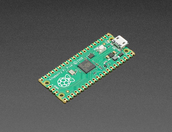
The Raspberry Pi foundation changed single-board computing when they released the Raspberry Pi computer, now they’re ready to do the same for microcontrollers with the release of the brand new Raspberry Pi Pico. This low-cost microcontroller board features a powerful new chip, the RP2040, and all...
distant spade

atomic ferry
Is there an example for a generic gamepad?
distant spade
no guide but an example: https://github.com/adafruit/Adafruit_CircuitPython_HID/blob/master/examples/hid_simple_gamepad.py
GitHub
USB Human Interface Device drivers. Contribute to adafruit/Adafruit_CircuitPython_HID development by creating an account on GitHub.
atomic ferry
Aha, thank you! I’m still learning the different sources for examples
distant spade
np, happy to point to places
we have a lot of docs but they aren't always easy to find
 worn zodiac
Is there a plan to support the Pi Pico PIO in CircuitPython?
 jaunty otter
Not really about pio, but I noticed that on the product page for the raspberry pi pico micropython book (product 4898), the link to the pico doesn’t work. It just links back to the book.
worn zodiac
@distant spade That's great! Where might I see examples? I'm really new to PIO (and it's been 30 years since I wrote any assembly), but I'd love to get back into it. #midlifecrisis 🙂
distant spade
jaunty otter
Not really about pio, but I noticed that on the product page for the raspberry p...
GitHub
Contribute to raspberrypi/pico-feedback development by creating an account on GitHub.
distant spade
worn zodiac
<@!252717193496756235> That's great! Where might I see examples? I'm really new ...
https://github.com/adafruit/Adafruit_CircuitPython_PIOASM/tree/main/examples and my stream https://www.youtube.com/watch?v=LXAwW2IYT7o
GitHub
Simple assembler to convert pioasm to bytes. Contribute to adafruit/Adafruit_CircuitPython_PIOASM development by creating an account on GitHub.
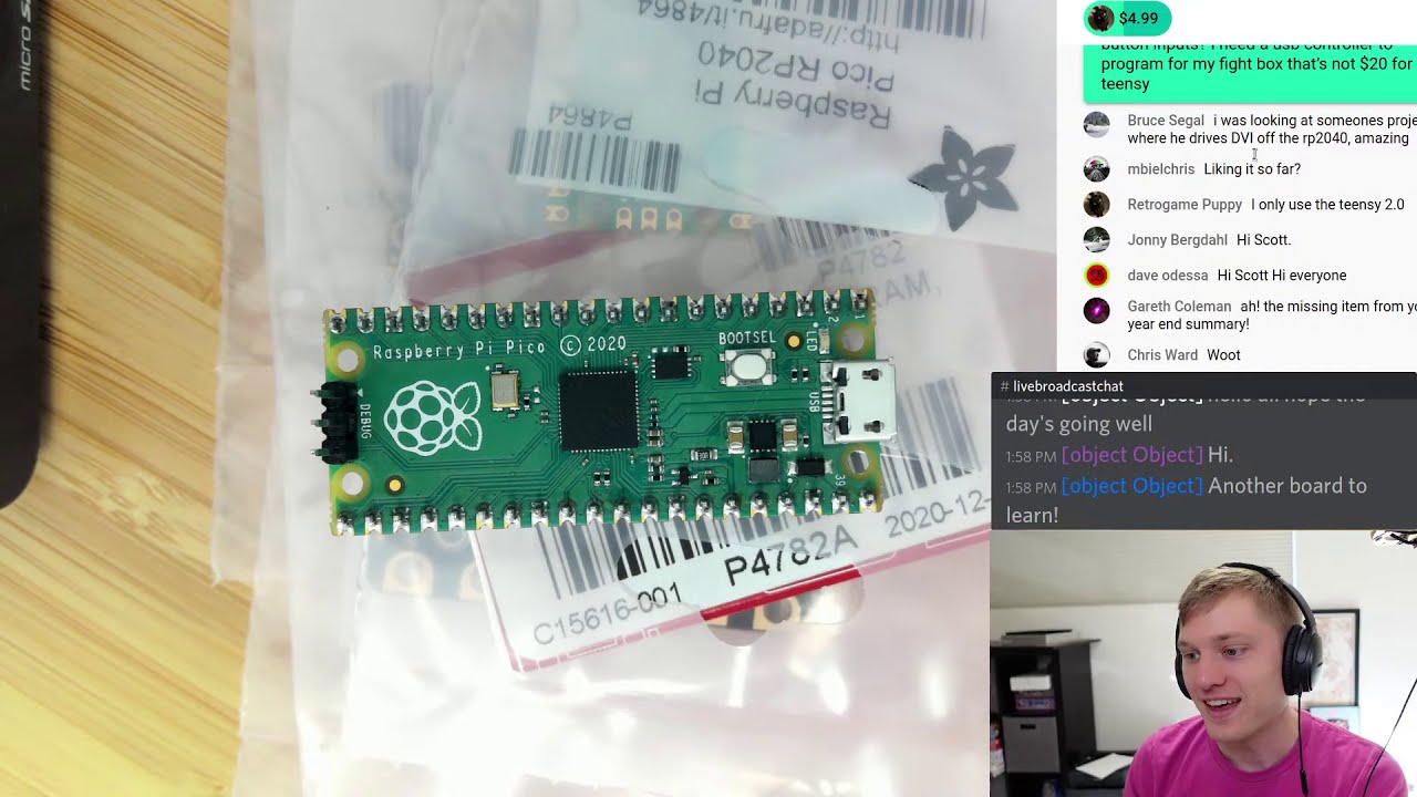
I’m sponsored by Adafruit to work on CircuitPython. Support them, and by extension me, by purchasing hardware from https://adafruit.com
Chat with me and lot of others on the Adafruit Discord at https://adafru.it/discord.
Deep Dive happens every week. Normally Fridays at 2pm Pacific but occasionally shifted to Thursday at 2pm. Typically goes for...
fair pagoda
What happened to GP15?
`Adafruit CircuitPython 6.2.0-beta.0 on 2021-01-22; Raspberry Pi Pico with rp2040
import board
hasattr(board, "GP15")
False
`
worn zodiac
fair pagoda
What happened to GP15?
`Adafruit CircuitPython 6.2.0-beta.0 on 2021-01-22; Raspb...
Get the beta1. It added it back in.
I had the same issue 2 days ago, @fair pagoda. LOL
A dir(board) showed me GP15 was missing. Reading the GitHub comments, looks like it's a "special use" pin also - something to do with USB. I didn't understand all of it.
fair pagoda
Maybe it's connected to the BOOTSEL button. Hmm...
frank quail
discussion is here https://github.com/adafruit/circuitpython/issues/4034
worn zodiac
Would PIO be useful to build something like a decoder with debounce for a quadrature encoder input?
Obviously, after the input side of things are working.
distant spade
maybe? you could do three samples and detect if it's zero still. not sure it's easy to detect if you are all ones though
 storm heath
I'm sure there are more elegant ways to do this, but I managed to get the "color wheel" working with PIO -- this example is for 7 Neopixel "jewel" -- cool stuff!
distant spade
awesome @storm heath !
 empty edge
wee. I have a LED blinking at human speeds in 4 instructions.
distant spade
it's a good place to start
empty edge
but I'm having some difficulty porting it from MicroPython to CircuitPython. pioasm_simpletest worked, but I use an out pin, not a set pin
distant spade
it's possible my out pin setup is wrong
I think I've only actually tested set and sideset
storm heath
@distant spade I was confused -- CP with PIO does match the MicroPython example -- but as you noted the order is reversed since they shift out all 24 bits -- so you have to set then in order g,r,b on the jewel with CP. slowly making sense.
storm heath
and confirmed by the WS2812 datasheet.
charred stone
@empty edge @distant spade I'm also having issues with the out pin. The pin seems to be floating.
Channel 1 should be the out pin output, channel 2 is the square wave example using set.
distant spade
@charred stone I think you need to set the pint to output from the PIO
you can add it as a set pin and then set the direction in init
or prepend the init code to your pio program but it'll take space then
neon dock
From @distant spade's implorations and Pepsi Python challenge during today's deep dive, I just flashed CP 6.2.0-b1 onto my 2nd pico. Compared to the work and setup needed just to run the demo "blink" code from the RPi "Getting Started Guide", it's not even a contest.
The guide way was several hours, with many brew install this that theother somethingelse larry darryl darryl, some more git clones, add in some cmake thiss and a sprinkle of ./configure that.
The CircuitPython way was about 5 minutes, from download to blinking LED, and mostly because I coded it manually in the REPL and couldn't quite remember the right imports and syntax off-hand.
 small meteor
I'm posting this here because its most pico related:
I'm trying to get the hello_world to work (this is the SDK for C/C++) I'm on an arch linux system:
I get this error when trying to cmake:
Using PICO_SDK_PATH from environment ('../../pico-sdk/')
Pico SDK is located at /home/carrot/CS Development/pico/pico-sdk
Defaulting PICO_PLATFORM to rp2040 since not specified.
Defaulting PICO platform compiler to pico_arm_gcc since not specified.
-- Defaulting build type to 'Release' since not specified.
PICO compiler is pico_arm_gcc
PICO_GCC_TRIPLE defaulted to arm-none-eabi
CMake Error at /home/carrot/CS Development/pico/pico-sdk/cmake/preload/toolchains/find_compiler.cmake:28 (message):
Compiler 'arm-none-eabi-gcc' not found, you can specify search path with
"PICO_TOOLCHAIN_PATH".
Call Stack (most recent call first):
/home/carrot/CS Development/pico/pico-sdk/cmake/preload/toolchains/pico_arm_gcc.cmake:20 (pico_find_compiler)
/usr/share/cmake-3.19/Modules/CMakeDetermineSystem.cmake:123 (include)
CMakeLists.txt:6 (project)
CMake Error: CMake was unable to find a build program corresponding to "Unix Makefiles". CMAKE_MAKE_PROGRAM is not set. You probably need to select a different build tool.
CMake Error: CMAKE_C_COMPILER not set, after EnableLanguage
CMake Error: CMAKE_CXX_COMPILER not set, after EnableLanguage
CMake Error: CMAKE_ASM_COMPILER not set, after EnableLanguage
-- Configuring incomplete, errors occurred!
[carrot@sys build]$ ```
https://datasheets.raspberrypi.org/pico/getting-started-with-pico.pdf
I'm following this guide and am on page 9 cedar valley
would like to convert the Raspberry Pi Pico Python SDK measure built in temp sensor with ADC channel #5 example on page 14 from MicroPython to CircuitPython and could use a how-to tutorial, any guidance would be appreciated. https://datasheets.raspberrypi.org/pico/raspberry-pi-pico-python-sdk.pdf
 robust wagon
@cedar valley Take a look to this guide. let me know if that helps. https://learn.adafruit.com/circuitpython-essentials/circuitpython-analog-in

@small meteor Hello, I could not help you with that but maybe you could try CircuitPython for the pico. https://circuitpython.org/board/raspberry_pi_pico/
The Raspberry Pi foundation changed single-board computing when they released the Raspberry Pi computer, now they’re ready to do the same for microcontrollers with the release of the brand new Raspberry Pi Pico. This low-cost microcontroller board features a powerful new chip, the RP2040, and all...
cedar valley
Thank you @robust wagon ! Was able to download CircuitPython onto the Pico and run hello world with the Mu Python editor. Will take a look at the analog tutorial and see what I can do
robust wagon
@small meteor I do not have a Pico but here you can see all the libraries supported with Circuitpython. https://circuitpython.readthedocs.io/projects/bundle/en/latest/drivers.html and you can read more in here also https://learn.adafruit.com/getting-started-with-raspberry-pi-pico-circuitpython/micropython-or-circuitpython
Adafruit Learning System
CircuitPython for Pico will get you started in minutes!
@cedar valley Nice 👍 enjoy you new Pico with CircuitPython
small meteor
Would C/C++ be more efficient compared to CircuitPython or is there any difference at all?
I'm trying to see if it'd be worth while trying to get C/C++ working on my system rather than using CircuitPython
@ me if you respond because I go to🌛 sleep good night
empty edge
@small meteor C is more efficient to run, since it's native machine code, but tougher to update (compile/download/debug), which hurts the experimenting feedback loop. You get direct access to everything though; CircuitPython has possibly limited interfaces. MicroPython has more raw access available, but equally less guidance such as diagnostics.
for instance, with a C program you'll want to add USB support and a command to start the bootloader again, just so you can load a new program without unplugging the board
or program it over SWD, requiring an adapter (which could be another pico)
note that PIO itself can't be programmed in C, so you're looking at the same assembly and performance in that. C is for the CPUs
 glacial sable
small meteor
Would C/C++ be more efficient compared to CircuitPython or is there any differen...
glacial sable
small meteor
Would C/C++ be more efficient compared to CircuitPython or is there any differen...
The Pio would be the same but the handling can be much faster in c.
glacial sable
pretty straight forward to get the c toolchain and sdk setup on linux.
tho there are a couple of things that are omitted in the raspberry pi foundation guides.
the default cmakelists file does not have
set(CMAKE_C_STANDARD 11)
set(CMAKE_CXX_STANDARD 17)
^ which had me stuck for a bit.
cedar valley
when using the Pico and Mu editor, does the MicroPython machine.ADC class have an equivalent in CircuitPython? using "board.ADC" throws an error. I am attempting to convert and run the MicroPython example on page 13 of the Pico Python SDK to CircuitPython https://datasheets.raspberrypi.org/pico/raspberry-pi-pico-python-sdk.pdf
 rapid stag
cedar valley
when using the Pico and Mu editor, does the MicroPython machine.ADC class have a...
rapid stag
cedar valley
when using the Pico and Mu editor, does the MicroPython machine.ADC class have a...
That code is MicroPython, not CircuitPython. We don't have machine in CircuitPython.
If you are trying to read the internal temperature sensor, do this for now:
>>> import microcontroller
>>> microcontroller.cpu[0].temperature
25.2659
However, after PR #4087 is merged, it will simply be microcontroller.cpu.temperature.
wanton pewter
@danh why the change? Are there sensors per-core or is it indeed one sensor?
https://github.com/adafruit/circuitpython/pull/4087 I see now, it's for compatibility with other boards but looks like individual core readings will still be available.
GitHub
This will allow microcontroller.cpu.temperature, etc. to work properly on an RP2040 or other multi-cpu chip. It will default to the values for cpu 0. In addition, it adds microcontroller.cpus, ind...
 wooden rune
has anyone tried the ST7789 display? trying to follow the docs but it doesn't seem as though the board.SPI() function exists on Pico?
frank quail
wooden rune
has anyone tried the ST7789 display? trying to follow the docs but it doesn't se...
you would need to use busio.SPI() with the pins you are using
https://circuitpython.readthedocs.io/en/latest/shared-bindings/busio/index.html#busio.SPI
(board.SPI when available is a shortcut to busio.SPI() with the default SPI pins on the board)
wooden rune
oh, thanks!
charred stone
Got my shift register emulator working.shiftreg = """ .program shiftreg .wrap_target wait 1 pin 1 out pins 1 wait 0 pin 1 .wrap """
wooden rune
@frank quail I think I have wired stuff up correctly but when I initialize using busio.SPI I get SPI peripheral in use?
wooden rune
wooden rune
<@!199811382793863168> I think I have wired stuff up correctly but when I initia...
@frank quail Never mind I figured it out, thanks for the push in the right direction!
frank quail
ah good, I was not sure I could help with that 😛
 gritty juniper
One thing I found was that when you create a StateMachine class instance, if you set the first_sideset_pin argument to the same pin as the first_set_pin argument (as in the ws2812 example), but then don't actually set the sideset value in the asm code, but do attempt to use the set instruction, the result will be that the pin output will not change. Or rather, it won't be set to a '1' simply using the set instruction.
For example, the following pio asm code results in the output pin (in this case, GP0) remaining low:
SQUAREWAVE_PIN = board.GP0 squarewave_program = """ .program squarewave again: set pins 1 [1] set pins 0 jmp again """ squarewave_assembled = adafruit_pioasm.assemble(squarewave_program) squarewave_sm = rp2pio.StateMachine( squarewave_assembled, frequency=1000000 * 4, # 1Mhz * 4 clocks per bit init=adafruit_pioasm.assemble("set pindirs 1"), first_set_pin=SQUAREWAVE_PIN, first_sideset_pin=SQUAREWAVE_PIN, auto_pull=False, )
Removing the "first_sideset_pin" argument fixes this. Just something to be aware of with side setting pins
In other words, if you have overlapping "set" pins and "sideset" pins, make sure to use the side option when setting the output to a "1". As it turns out, setting the output to a "0" works using the set instruction even without the side option. In fact, it appears that set pins 0 and set pins 0 side 0 have the same resulting opcode (0xe000)
 thorny meteor
wooden rune
<@!199811382793863168> I think I have wired stuff up correctly but when I initia...
thorny meteor
wooden rune
<@!199811382793863168> I think I have wired stuff up correctly but when I initia...
What was it?I am having the same issue and no idea how to fix it.
charred stone
gritty juniper
In other words, if you have overlapping "set" pins and "sideset" pins, make sure...
This is because the delay and sideset pins are encoded in every instruction even if not explicitly set
wooden rune
thorny meteor
What was it?I am having the same issue and no idea how to fix it.
I switched from SPI0 to SPI1 pins (from gp16,17,18,19 to gp10,11,12,13)
lucid garnet
Vga output via PIO?? https://youtu.be/WaPJmCgseQw
 tight chasm
Hi everyone ! I was trying some stuff with my Pico using CircuitPython.. But I think I messed up somewhere..
So I wanted to use a library wich is present into CircuitPython bundle.. It is adafruit_dht.. But whenever I try to use it into my code I get this error :
>>> import adafruit_dht
>>> dhtDevice = adafruit_dht.DHT11(board.GP15)
Traceback (most recent call last):
  File "<stdin>", line 1, in <module>
  File "adafruit_dht.py", line 264, in __init__
  File "adafruit_dht.py", line 52, in __init__
Exception: Bitbanging is not supported when using CircuitPython.
(sorry in advance for some of my english mistake.. French is my mother language 🙂 )
storm heath
@tight chasm teh dht library trues to use pulseio but that is not present on the pico -- when it does not find pulseio it tries to use bitbang but that is not supported... I'm not sure if pulseio is just not implemented yet or if the DHT library need to be updated.
tight chasm
oh okey thanks for your quick answer 🙂
rapid stag
pulseio.PWMOut is deprecated in 6.x, will be removed in 7.x. It's just a renaming. pulseio.PulseIn and PulseOut will still be in pulseio.
storm heath
so it looks like pulseio is just not implemented for the rp2040 yet.
rapid stag
right
tight chasm
Ok got it, I'll just wait for it to be implemented, for now I will just mess with an other sensor 👍
storm heath
Good luck -- the pico is fun to explore!
tight chasm
First time messing with microcontroller.. It's cool ! Did a traffic light for now lol
storm heath
If you have any sensors that use I2C or SPI, they should work well.
small meteor
Can Pi Pico be used with C++ or only python variants
 nova fern
it can use both. (you'd find that out pretty quickly with a google search)
 storm mantle
Trying to set a pin to a high impedance state so I can drive a led matrix. I tried setting the pin as an input but it still sinks enough current to light dimly.
I looked in the datasheet and it seems like it should be possible but I can't figure out how to do it using the SDK. I guess the next step is to try manipulating the pins at the register level without the SDK.
Page 27 of the RP2040 data sheet indicates that GPIO_OE and GPIO_HI_OE have to be set to 0 to set the pin to a high impedance state but I don't see a way to do this with the SDK.
glacial sable
/*! \brief Set a single GPIO direction
 *  \ingroup hardware_gpio
 *
 * \param gpio GPIO number
 * \param out true for out, false for in
 */
static inline void gpio_set_dir(uint gpio, bool out)
That is the function that my code uses to set the pin as an input but it still sinks a fair amount of current when set as an input.
I think I need to set the bit corresponding to the pin in the GPIO_OE register to 0. Not quite sure how to do that though.
looking at the SDK repo now.
glacial sable
leakage should only be ~1 uA iovdd <= 3.6
tho just setting pin to input i'm getting 55uA. : s
storm mantle
Thank you for confirming that.
glacial sable
ok maybe i have the answer for you
disable pulls up/downs on your input
@storm mantle gpio_disable_pulls(INPUT)
leakage drops to a few nA for me.
3uA at 3.6V, 1.3nA at 3.3V
storm mantle
Cool,  that did the trick!
Would be nice if there were a way to disable_pulls with a mask.
 sour bone
I'm looking for some help with the pico wiring/code. Can I post schematics here? Be gentle this is all new to me.
sour bone
I've documented the attempt so far to get a TMC2226 driver working with a Raspberry Pi Pico on github. I'm guessing something is wrong with my wiring? Could someone more knowledgeable about this stuff take a look at the readme? https://github.com/atrueresistance/pico-micropython-examples/tree/master/stepper motors/TMC2226

GitHub
Examples to accompany the "Raspberry Pi Pico Python SDK" book. - atrueresistance/pico-micropython-examples
distant spade
@sour bone it looks like your driver chip takes a UART connection
sour bone
Oh, not sure what that means. . or at least am not smart enough yet. I'll see what I can google. Are there any UART examples? I don't remember seeing any in the official pico book.
distant spade
I recommend starting with an adafruit learn guide and using the parts from us: https://learn.adafruit.com/all-about-stepper-motors

Adafruit Learning System
The Adafruit guide to choosing and using stepper motors.
parts from amazon tend to be cheap but not documented
(full search: https://learn.adafruit.com/search?q=stepper )
thorny meteor
wooden rune
I switched from SPI0 to SPI1 pins (from gp16,17,18,19 to gp10,11,12,13)
No diff in my case, keep getting message that SCLK pin is in use, doesn't matter which pin I use
fair pagoda
You may need to power cycle the Pi Pico to free up the SPI pins.
small meteor
So the rp2040-pio doesn't run Linux, right? langostino
storm heath
right
It is like many other MCU's ,runs whatever you load to it -- no built in OS.
I have not tried the C/C++ SDK yet, but MicroPython and CircuitPython work well. Lots to learn about PIO.
small meteor
So somebody really wanted this to work for Python. ;)
I'm guessing the price point would be critical to that motive.
storm heath
The C/C++ SDK looks interesting too -- just need to find time to explore it. https://datasheets.raspberrypi.org/pico/raspberry-pi-pico-c-sdk.pdf
small meteor
I take it there's a datasheet describing the main chip(s) for this board.
small meteor
Thank you!
storm heath
lots of other docs available here https://www.raspberrypi.org/documentation/pico/getting-started/ scroll down a bit
small meteor
I'm wondering if 'threading' is relevant considering two separated M0 cores (I think I read that somewhere). Or if the two ersatz/real MCU's are programmed as if they were two cores connected via some kind of bus.
storm heath
¯_(ツ)_/¯ 😉
small meteor
I mean, Chuck (Moore) has 144 cores in a single chip and I have no idea how the programming interface leverages all that complexity. ;)
glacial sable
well if its chuck it will be forth
storm heath
only a matter of time before forth is available for the RP2040 -- if it is not already -- have not looked.
glacial sable
i looked, thought about porting it for a few minutes, then got onto something else.
small meteor
This sounds pretty useful:
Code may be executed directly from external memory through a dedicated SPI, DSPI or QSPI interface
glacial sable
xip
small meteor
2.1 Bus Fabric helps me to appreciate wigoh:
https://datasheets.raspberrypi.org/rp2040/rp2040-datasheet.pdf
glacial sable
the abh with pio and dma is the nicer imo
small meteor
And 2.1.1 AHB-Lite Crossbar - that's exciting!
glacial sable
32bit word xfer per cycle, thats nice
small meteor
Wow this thing is really something.
glacial sable
have a look at https://github.com/raspberrypi/pico-examples/blob/master/pio/logic_analyser/logic_analyser.c I think thats neat.
small meteor
the Pico SDK provides higher level libraries for dealing with timers, synchronization, USB (TinyUSB) and multi-core programming along with various utilities
from
https://github.com/raspberrypi/pico-sdk
CMakeLists.txt is more than Oh I am sure they did the right thing - I won't look at it vis a vis two variant Hello World programs:
https://github.com/raspberrypi/pico-examples/blob/master/hello_world/usb/CMakeLists.txt#L8
glacial sable
i made a few mods
cmake_minimum_required(VERSION 3.12)

set(NAME projectname)

set(PICO_SDK_FETCH_FROM_GIT on)
set(PICO_SDK_PATH off)
include(pico_sdk_import.cmake)

project(${NAME} C CXX ASM)
set(CMAKE_C_STANDARD 11)
set(CMAKE_CXX_STANDARD 17)

pico_sdk_init()

add_executable(${NAME}
    hello.c
)

target_link_libraries(${NAME}
    # libs here!
)

pico_set_program_name(${NAME} "Meta Title")
pico_set_program_description(${NAME} "Meta Desc")
pico_set_program_version(${NAME} "0.0.0")
pico_set_program_url(${NAME} "meta URL")

# Add pico_stdlib library which aggregates commonly used features
target_link_libraries(${NAME} pico_stdlib)

# create map/bin/hex/uf2 file in addition to ELF.
pico_add_extra_outputs(${NAME})

pico_enable_stdio_usb(${NAME} 1)
pico_enable_stdio_uart(${NAME} 0)

add_custom_command(TARGET ${NAME}
    POST_BUILD
    COMMAND picotool info -a ${CMAKE_CURRENT_BINARY_DIR}/${NAME}.uf2
    VERBATIM
)
the git fetch will blow out the project folder out to something like 2.5ish GB tho
small meteor
;)
glacial sable
it just the way i like to have dependencies. all in project.
small meteor
Looks like drag n drop .UF2 is the usual method to update firmware.
thorny meteor
fair pagoda
You may need to power cycle the Pi Pico to free up the SPI pins.
trying to make it work with st7789 screen but maybe i should start with something more simple to see if SPI really works
glacial sable
drag and drop get a little annoying for dev cycles, but it works for everyone.
@thorny meteor did you try the https://github.com/raspberrypi/pico-examples/tree/master/pio/st7789_lcd/
glacial sable
reminds me i need to try openocd on rp2040,
small meteor
https://datasheets.raspberrypi.org/pico/getting-started-with-pico.pdf
has the git commands to manually install, I think (working on it now).
2.1. Get the SDK and examples
The introductory paragraphs do mention the default system is a Raspberry Pi, which I had overlooked.
And it's gonna want this:
$ apt install cmake gcc-arm-none-eabi libnewlib-arm-none-eabi build-essential
with a sudo there ;)
I don't know if it will like what Debian (AMD64) gives as 'gcc-arm-none-eabi' ;)
small meteor
Thanks!
I had been using a special version d/l from ARM per the CircuitPython building instructions.
glacial sable
they guide in their sdk getting started is fine, just follow that
i'll see if i can fine the link
i have arm's compiler too.
as well as
small meteor
I usually keep arm's version in ~/dev
(in this case /dev means develop not device ;)
Then I run a custom ~/.profile
I found that I could freely change ~/.profile and start a new xterm, then reinstate the usual profile, and everything works as expected.
glacial sable
source ~/.profile also is good for that
small meteor
Only the specially started xterm has the unusual $PATH to point to ~/dev.
Oh okay I'll have to try that.
Thanks.
glacial sable
this is the guide i used https://datasheets.raspberrypi.org/pico/getting-started-with-pico.pdf
and the only issue i had was with the CMakeLists.txt
i needed to spec the standards for c and c++
these lines
set(CMAKE_C_STANDARD 11)
set(CMAKE_CXX_STANDARD 17)
oh and https://github.com/raspberrypi/pico-sdk/blob/master/README.md has some notes on the cmake stuff for how to include the sdk.
small meteor
;)
Just so long as I don't have to use an RPi itself, and most of debians official tools work, I'm probably fine.
Wants (or prefers) Doxygen. 25 MB to me and 3 .deb files -- not bad.
$ strings blink.elf | fmt -w64
Suggestive of a good build and has lots of files and their paths listed. ;)
This doesn't look bad at all.
13 kb for the .bin file.
The .hex is 37 kb and the .uf2 is 26 kb. ;)
small meteor
2.2 Install the Toolchain
https://datasheets.raspberrypi.org/pico/getting-started-with-pico.pdf
Debian AMD64's satisfaction of gcc-arm-none-eabi worked fine.
The only outlier was it also wants doxygen.
There were no python extortions at all .. no use of pip.
Whoops wrong channel. sorry.
(thought I was telling this in the Arduino server!)
storm heath
I already had gcc-10 installed so I just bypassed the gcc install -- works fine
small meteor
Yeah it's great - when I get hardware I'll like this SDK environment.
storm heath
Just working through some of the SDK examples -- blink/hello_world work, woohoo! about to try hooking up to an RPi via SWD and try openocd.
small meteor
;) nice.
 open kelp
has anyone tried using the microSD breakout board with the Pico?
I'm getting errors
AttributeError: 'SPIDevice' object has no attribute 'spi'
complete error is: Traceback (most recent call last):
File "code.py", line 19, in <module>
File "adafruit_sdcard.py", line 101, in init
File "adafruit_sdcard.py", line 122, in _init_card
File "adafruit_sdcard.py", line 110, in _clock_card
AttributeError: 'SPIDevice' object has no attribute 'spi'
storm heath
Woohoo! Openocd works! Using RPI 400 to pico. Very nice!
open kelp
@storm heath good to know about the microSD card issue being known. I have the same error on Pico and ESP32S2 metro
storm heath
Not sure about status on Pico
If I recall the conversation correctly, it may impact all boards with the latest builds.
open kelp
I tested with success on a xiao today with adafruit-circuitpython-seeeduino_xiao-en_US-6.2.0-beta.1.uf2
small meteor
@slate palm The schottky diode, D1, separates VBUS from VSYS in the schematic, Figure 14.
So, VSYS cannot backfeed J1 (looks like USB microB there at J1).
If VBUS is 5.0 V then VSYS is around 4.75 V (one schottky diode drop below VBUS).
 slate palm
Thank you!
small meteor
The datasheet spelled it out in quite a bit of detail, and covered each contingency .. I didn't realize that when I posted the above comment (which is correct but not comprehensive).
They did a superb job documenting power considerations. ;)
slate palm
👍
small meteor
The thing about a schottky diode is it has a low forward voltage drop (around 0.28 V) compared with other kinds of diodes, which are sometimes closer to 0.7 V. So the schottky variety is particularly well suited for insertion inline like this.
slate palm
oh those power curves showing sleep state are nice
small meteor
I got four oversized shottky diodes from DigiKey for 44 cents apiece. ;)
pale cosmos
When you want to make sure power goes only one way, sometimes you really need to give it your best Schottky.
(although I am fond of ideal diodes as well)
small meteor
import board
from time import sleep
#disable warnings (optional)
GPIO.setwarnings(False)
#Select GPIO Mode
GPIO.setmode(GPIO.BCM)
#set red,green and blue pins
redPin = 24
greenPin = 25
bluePin = 26
#set pins as outputs
GPIO.setup(redPin,GPIO.OUT)
GPIO.setup(greenPin,GPIO.OUT)
GPIO.setup(bluePin,GPIO.OUT)

def turnOff():
    GPIO.output(redPin,GPIO.HIGH)
    GPIO.output(greenPin,GPIO.HIGH)
    GPIO.output(bluePin,GPIO.HIGH)

def white():
    GPIO.output(redPin,GPIO.LOW)
    GPIO.output(greenPin,GPIO.LOW)
    GPIO.output(bluePin,GPIO.LOW)

def red():
    GPIO.output(redPin,GPIO.LOW)
    GPIO.output(greenPin,GPIO.HIGH)
    GPIO.output(bluePin,GPIO.HIGH)

def green():
    GPIO.output(redPin,GPIO.HIGH)
    GPIO.output(greenPin,GPIO.LOW)
    GPIO.output(bluePin,GPIO.HIGH)

def blue():
    GPIO.output(redPin,GPIO.HIGH)
    GPIO.output(greenPin,GPIO.HIGH)
    GPIO.output(bluePin,GPIO.LOW)

def yellow():
    GPIO.output(redPin,GPIO.LOW)
    GPIO.output(greenPin,GPIO.LOW)
    GPIO.output(bluePin,GPIO.HIGH)

def purple():
    GPIO.output(redPin,GPIO.LOW)
    GPIO.output(greenPin,GPIO.HIGH)
    GPIO.output(bluePin,GPIO.LOW)

def lightBlue():
    GPIO.out
"Traceback (most recent call last): File "<stdin>", line 2, in <module> ImportError: no module named 'board'"
pi pico thonny
frank quail
don't import board
what is that code from ?
and for ?
looks like raspberry pi RPi.GPIO module but it doesn't import it ?
frank quail
"no module named board" makes me wonder if it's running on a Pi or Micropython
small meteor
.. oh
frank quail
right
small meteor
I figured it would be the saem..
frank quail
the pico's confusing branding strikes again
storm heath
other than it's creator, the Pico has nothing to do with a Raspberry Pi
frank quail
you want to look at code for Micropython or Circuitpython, depending on what you are using, not generally "Raspberry Pi", or you're gonna get code for the linux computers (which the pico isn't)
small meteor
frank quail
you want to look at code for Micropython or Circuitpython, depending on what you...
oh.
storm heath
@small meteor What are you trying to do?
small meteor
I have a 4 pin RGB LED that i want to change colors with just because
storm heath
Are you using MicroPython or CircutPython?
small meteor
Thonny Micropython
storm heath
Have you tried the demo in the micropython book https://hackspace.raspberrypi.org/books/micropython-pico you can download it free -- the "hello,LED" example ahows you how to control the onboard LED -- then you can expand it for your 3 LEDs.
see Chapter 4 (but don't skip 1-3 ) 😉
small meteor
Did my pico just die? It got unpluged while running a script and now even holding boot sel it wont show drive info
Nope. Just the USB port wasnt working
Okay, now my question, (sorry if this can all be read in the starter guide) From thonny after pressing run how do i save the program to my pico, because when re plugged it forgets it?
storm heath
If you were editing it on the pico -- it should save it there. Make sure you are working on the Pico and not locally. click file/Save as and save it on the Pico. Also the file name in the tab at the top should have square brackets [] surrounding it if it os on the Pico.
small meteor
Does it have to be named anything special?
storm heath
to run automatically it should be main.py -- but to run it from Thonny no, it can be anything -- with some limitations - what are you calling it?
storm heath
that should be OK
do you have the "Files" panel open -- click on View and select Files. It will show you your local and Pico files
small meteor
storm heath
I don't think that will do anything -- main.py will run at boot. At least I don't know how to avoid it.
small meteor
Okay, regardless, i got it to do what i wanted, with help from you of course, appreciate it
small meteor
thanks
thorny meteor
small meteor
*<https://datasheets.raspberrypi.org/pico/getting-started-with-pico.pdf*> points...
no, I tried only the example from CircuitPython library, will give this one a shot thx
storm heath
@small meteor FYI . This explains how to uses the RUN pin https://www.raspberrypi.org/blog/how-to-add-a-reset-button-to-your-raspberry-pi-pico/?fbclid=IwAR1s4-Ij6HI0OQqa1JygX_uRFMnXvNFsQ2_ppF6n20ve0KmAL4dyB-V-EJM it just resets the board when grounded.
tight chasm
Was anyone able to make adafruit_character_lcd to work with a Pico ?
 exotic moth
@tight chasm If you're referring to CircuitPython, you'll be better off asking in the #help-with-circuitpython channel. This is more for topics specific to the chip.
tight chasm
Ok I'll do that
slate palm
@small meteor If it makes you feel better I've done the same thing like 5x in last 48 hours. I assumed my RPi Python code would just easily move over....doh.
 uneven plaza
If you solder the pins of Pi Pico upside then you can see their description and place also buttons for RESET (pins RUN and GND) and BOOTSEL (pins TP6 and GND)...
slate palm
Is that more helpful for you than soldering it right side up and hitting the BOOTSEL button or unplugging USB?
So I'm chasing down weird issues with my Pico and trying to get this ultrasonic sensor working
I can completely remove the us sensor and trigger the echo pin by touching a wire
did I do something wrong in setting up the pins?
trigger = digitalio.DigitalInOut(board.GP21)
trigger.direction = digitalio.Direction.OUTPUT
echo = digitalio.DigitalInOut(board.GP22)
echo.direction = digitalio.Direction.INPUT
 nocturne lark
frank quail
you want to look at code for Micropython or Circuitpython, depending on what you...
nocturne lark
frank quail
you want to look at code for Micropython or Circuitpython, depending on what you...
Micropython and Circuitpython are bare metal languages for Microcontollers
worn zodiac
Is frequency the frequency at which the PIO program executes or is the number of clock cycles per instruction? In other words, if I set frequency=2000 would that mean the state machines are running at 2kHz or 66.5kHz (133 MHz / 2000)?
worn zodiac
Also, is the lowest frequency 2000?
distant spade
@worn zodiac it'd be 2khz or so
there is math to determine the closest divisor
GitHub
CircuitPython - a Python implementation for teaching coding with microcontrollers - adafruit/circuitpython
gritty juniper
uneven plaza
If you solder the pins of Pi Pico upside then you can see their description and ...
That makes a lot of sense. I cannot for the life of me understand why the RPI folks didn't silkscreen the pin names on the top side of the board (you know, where they can be seen...). I also like the reset button addon. Nice workaround, @uneven plaza!
worn zodiac
distant spade
<@!750460739881402480> it'd be 2khz or so
Thank you, @distant spade. I found the docs on readthedocs. Guess, I should get an RTFM sticker now 🙂
distant spade
np
distant spade
gritty juniper
That makes a lot of sense. I cannot for the life of me understand why the RPI f...
hopefully they'll revise the board and add them
worn zodiac
If I wanted to use PIO for PWM where it sends the same 32-bit word in a loop until the Output FIFO is written by a new value, how would I do it? I'm thinking something like the below:
Set Autopull true
Write initial word to FIFO
Copy word to X
Loop:
    Out from OSR to pin.
    If Shift counter > 0
        Goto Loop
    else
        Copy from X to FIFO
        Goto Loop
And, to write out a new value, I'd just call write in my CPY code. This would overwrite the FIFO. Although I'd need it to copy the FIFO to X before this loop starts. Ugh!
distant spade
I've thought about this. I think the state machine needs to check the fifo and if its empy, move a value from x or y into the osr
I haven't tried it myself yet
I need something similar for transmitting I2S
worn zodiac
Once the FIFO is PULLed, it's empty, right? That was my assumption. Not sure if it's right or not.
distant spade
yup, it nothing else has been added
worn zodiac
I see this in the RP2040 datasheet (section 3.4.7.2):
Block: If 1, stall if TX FIFO is empty. If 0, pulling from an empty FIFO copies scratch X to OSR.
A nonblocking PULL on an empty FIFO has the same effect as MOV OSR, X. The program can either preload scratch register
X with a suitable default, or execute a MOV X, OSR after each PULL NOBLOCK, so that the last valid FIFO word will be recycled
until new data is available.
I guess you could set AutoPull OFF, and then just PULL noblock when the OSR is empty.
So much to learn... 🙂
worn zodiac
Their instruction set design is so thoughtful
slate palm
Should I be able to trigger a 1 on an input pin just by touching a wire?
Trying to get an ultrasonic sensor working and it's behaving very erratically.
basically the same whether or not the sensor is in play...
I have the 5V version of the HC-SR04, I suspect that's actually the issue.... Have a voltage divider to 3V on the echo pin. Acting super weird.
 silent gyro
have anyone found a good instruction for setting up a debian/ubuntu computer for developing c/c++ for the pi pico WITHOUT using vscode(ium)?
i prefer using emacs or kate(KDEs texteditor, has builtin c/make tools)
I just got mine and im having issues getting make to compile my project
lucid garnet
slate palm
Should I be able to trigger a 1 on an input pin just by touching a wire?
If you are at the same voltage, I think gnd is low and that voltage is high/1. But if it's a 5v device that's trying to talk to a 3v pico, you might need more than a voltage divider for logic communication
The threshold for high on 5v is different than 3v
So if you arbitrarily get a 5v high signal to be 3v it still might not be the right thing to trigger a 3v high
Someone who knows more can provide better insight
slate palm
The sensor goes 5V high/low on the Echo return pin after it received the chirp. But yeah, I think my issues are stemming from the logic levels.
I actually need a longer range distance sensor for my real project, I just had these. Im going to stop trying with these and buy something with 3.3V compatibility and probably UART.
Looks like Adafruit has a few choices
lucid garnet
Probably good unless you want to get a logic level shifter
You can also use a mosfet and have your 5v logic open a gate to the pico 3v output
@slate palm
slate palm
That makes sense
RPi needs to just make a Pico+ board that operates on 5V logic instead 😂
small meteor
@silent gyro I didn't have any issues - good compile.
It did want 'doxygen' which is a bit unusual.
Everything else seemed reasonably standard.
Scroll back here, I posted some notes as I went.
$ apt-get install cmake gcc-arm-none-eabi libnewlib-arm-none-eabi build-essential doxygen
Looks like my first RP2040 board will arrive on Monday or Tuesday!
worn zodiac
silent gyro
have anyone found a good instruction for setting up a debian/ubuntu computer for...
I have not tried it, although I did set up my RPi to operate like that. I found the instructions in the "Getting Started" guide to not be the most organized, and it took me a couple of failures to realize that, e.g. you need to start the build from the build subdirectory.
I'm a huge fan of VSCode, and since I couldn't set up the compiler on my M1 Mac, I installed all the tools on the Pi, and used VSCode's Remote extension to develop on it. Works great!
silent gyro
worn zodiac
I'm a huge fan of VSCode, and since I couldn't set up the compiler on my M1 Mac,...
I can't stand VSCode for more than a couple of minutes before I get angry at it...
Just like with windows...
silent gyro
worn zodiac
I have not tried it, although I did set up my RPi to operate like that. I found ...
Yeah
That seems to be the biggest issue for me too
Is there a way to get the pico to show up as a Linux writable device file?
ie is there a way of doing something similar to how you can write a 0/1 to the caps/num/scroll lock LEDs but with the Pico?
I'm thinking "scriptable ((ba/z)sh) neopixels that are controlled by echoing to files in the filetree.
Making it work as a usb drive (outside of program retrieval mode) would probably work too
Assuming I can read those files through the C/C++ code
distant spade
silent gyro
Is there a way to get the pico to show up as a Linux writable device file?
ie i...
Take a look at CircuitPython. It shows up as a drive by default and also supports HID
fair pagoda
Anyone remember Styx (not the band, 9p for embedded devices.)
small meteor
;)
 keen quest
Did that run the Lorelei operating system?
silent gyro
distant spade
Take a look at CircuitPython. It shows up as a drive by default and also support...
I dont know python
I dont Want to learn python
I dont like the syntax of python
I wont use python
lua for the win
1 based indexes anyone?
minor parcel
you might be in the wrong place then
I mean, you are welcome and all that, but there is a risk we will manage to convert you
lucid garnet
Is there any way to pull a unique identifier off an rp2040 device? Like a chip serial number or whatnot that can be used for validating customers in some way?
storm heath
microcontroller.cpu.uid
but I'm not sure it has been fully implmented for the rp2040 -- I am not getting consistent values
frank quail
the flash chip has a unique identifier, which is used by Circuipython to provide a serial number, though i'm not sure if that's implemented yet (there's an open issue on it, I believe it requires updating the version of the SDK used maybe), but here is a (merged) PR that lets you do that in the pico SDK: https://github.com/raspberrypi/pico-sdk/pull/12
distant spade
lucid garnet
Is there any way to pull a unique identifier off an rp2040 device? Like a chip s...
I've snuck it into my audio work that also updates the pico-sdk. The chip itself has no id so we use the flash one.
lucid garnet
Ok, can the flash chips be as easily read/ altered as eeprom stuff?
/is there a way to modify the flash id?
I'm considering editing a CP build to have production code running on it, and linking an encrypted text file using people's id to prevent sharing
 vagrant widget
if you can run the decryption on the rp2040
then an attacker can just run your code in an emulator, and dump the decrypted version
distant spade
lucid garnet
/is there a way to modify the flash id?
No, I believe the id is fixed.
lucid garnet
Let me take a step back and start from my goal I guess. I want to be able to provide new software or programs in a way that they can't just be shared and dropped onto the device for someone who didn't buy it. I was imagining having like a game engine on the booting uf2 and game data on a file but need a way that they can't be shared and ran on another device in some way
vagrant widget
not really possible with the current rp2040 chip
lucid garnet
Or at least, by regular people
frank quail
so like a user-specific signature on the data that the code would check ?
vagrant widget
there is currently no way to encrypt the code
the best you can do is to just read the unique id and stop if it doesnt match
anything more complex is just a waste of time and can still be undone
lucid garnet
Yea, so each person would have their Id embedded somehow in the game code txt, and the engine would check to see if that specific code was there before running. So a specific uf2 with the program would need to be made for each device that checks against it's code before running
And also that it matches what's on the flash.
vagrant widget
yep
lucid garnet
Can you pull uf2s off of devices and decrypt them easily?
vagrant widget
they arent encrypted
lucid garnet
I mean
vagrant widget
so you can use SWD or picotool to just dump the entire thing
and then just pass it thru objdump -D to disassemble it
lucid garnet
Like take a uf2 and get it back into python
vagrant widget
if your using micropython, i think the raw python source is just saved directly to the flash
lucid garnet
Circuit python
vagrant widget
frank quail
~~by copying CURRENT.UF2~~
the RP2040 doesnt have that file available in its rom
frank quail
ah my bad
lucid garnet
Ok, so if I put a uf2 on the rp2040 it cannot be pulled back? Only wiped?
vagrant widget
picotool and SWD still allow dumping
vagrant widget
yeah
vagrant widget
not really, because the RP2040 doesnt support crypto, so the code must be decrypted outside of the cpu, and pass plaintext over the QSPI bus
the most you can do is just confirm that the crypto chip has a given key, but now your just repeating the same thing i said before:
the best you can do is to just read the unique id and stop if it doesnt match
anything more complex is just a waste of time and can still be undone
and your code cant be protected, so i can just dump it and remove that condition
lucid garnet
Lol I heard that but I have to get all my ideas out to get shut down before I can step away from them 😅
Well if there's no usb access to the chip itself you'd have to desolder the chip to do that, right?
vagrant widget
SWD can still dump it
lucid garnet
I mean, if there's no physical way to connect to the rp2040 at all
vagrant widget
the only way to stop dumping, is to block access to SWD and the BOOTSEL button
encase the whole board in epoxy!!
the usb is fine, since your firmware controls what usb can do
lucid garnet
Ro2040!=pico
Oh,
So, what do you mean by swd being able to dump it if the firmware controls usb stuff?
vagrant widget
the BOOTSEL mode can only be entered via 3 routes:
- hold the BOOTSEL button on startup
- have an invalid stage2 in the flash
- have the current code run a function to reboot into BOOTSEL mode
lucid garnet
There is no button on an rp2040 chip
vagrant widget
SWD gives full control of the chip, more then BOOTSEL mode, allowing read/write/erase and debug
if you have a bare chip, you choose where the button on the board goes, or can just not put a button on it
lucid garnet
So with swd you'd still need a pad exposed right?
vagrant widget
yeah
but if this was a custom pcb without those pads
well, i could just desolder the spi flash chip, then dump it directly, or transplant it onto a regular pico board
lucid garnet
Yes, but then you'd be one person who has access to a dumped and rewritten firmware and no one else could benefit afterwards unless they also desoldered?
vagrant widget
i could then upload the firmware to a random website, and now everybody has it
vagrant widget
use a regular pico, or make a clone of the pcb, without those limitations
lucid garnet
A normal user would not reassemble a board with buttons and screen and whatnot after writing the dumped code to a pico
vagrant widget
but what about an evil user? take it apart, dump the firmware, clone the pcb, re-sell it for half the cost and not have to develop the firmware
lucid garnet
That person will have to invest a good amount of time and money and would not be providing the same user experience
Buttons, screen, layout, shell, etc
distant spade
My opinion is that it's not worth your time worrying about code security. Spend that time building your brand and therefore brand loyalty
code security won't help if someone re-implements your thing with more features
lucid garnet
Ya. I'm fine at one point opening things up. But I don't want it to be as simple as copying and pasting a txt file onto the device that can be shared easily on day one
One step removed from that would be ideal I guess
worn zodiac
I'm trying to write a simple PWM program using the PIO. I don't have an oscilloscope or logic analyzer worth its salt. Any chance someone could take a look at this program and see if (a) the logic is correct, and (b) whether the PWM is actually being set correctly? I'd really appreciate it:
import time
import rp2pio
import board
import adafruit_pioasm


init = """
set pindirs 1
set x 0
"""

pwm = """
.program pwm
.wraptarget
pull noblock
mov x osr
out pins 32 [31]
.wrap
"""

# squarewave = """
# .program squarewave
#     set pins 1 [31]  ; Drive pin high and then delay for one cycle
#     nop [31]
#     nop [31]
#     nop [31]
#     set pins 0 [31]  ; Drive pin low
#     nop [31]
#     nop [31]
#     nop [31]
# """

#assembled = adafruit_pioasm.assemble(squarewave)
pwm_assembled = adafruit_pioasm.assemble(pwm)

sm = rp2pio.StateMachine(
    pwm_assembled,
    frequency=2000,
    init=adafruit_pioasm.assemble(init),
    first_out_pin=board.GP16,
    auto_pull=False
)

zeros = b"0"
ones = b"11111111111111111111111111111111"
half = b"00000000000000001111111111111111"
quarter = b"00000000000000000000000011111111"

i = 0

while i < 5:
    print("Writing Ones: ", int(ones, 2))
    sm.write(ones)
    time.sleep(5)
    print("Writing Quarter: ", int(quarter, 2))
    sm.write(quarter)
    time.sleep(5)
    i = i + 1

sm.write(zeros)
how are you going to use it?
worn zodiac
I'm literally playing around. My hope was to use it in a motor driver - when I get around to it.
But first, I was hoping that it'd help me learn PIO ASM. I think the logic is correct, but I can't tell. Using an LED doesn't help, I think the data shifts out too fast for the duty cycle to show a perceptible difference in brightness to the human eye.
distant spade
ya, brightness tends to be non-linear so you'll only be able to perceive the smallest values
you could use a second pico (or pio) to capture the signal
worn zodiac
That's a good idea... So, read it in via an input GPIO and see if I can't print it out?
BTW, how far off are you from the RP2PIO being able to read in data from the input FIFO?
And, just for my understanding, when the OUT command is executed to shift out 32 bits, the pin should be seeing a bit shifted out each cycle (i.e. it takes 32 cycles to shift out 32 bits). Correct?
distant spade
I'm busy with audio but the underlying code is there. it just isn't connected up
out sets the number of bits you specify for that cycle
so 32 would set each pins value
at the same time
worn zodiac
Ah! That's interesting.
So, 32 would require an array of 32 pins for it to work? Not just one?
Or, does it mean that it shifts out 32 bits in one clock cycle - which might explain why I can't see anything on my crappy 200khz "homebuilt" oscilloscope.
small meteor
Where's the documentation for what you're trying to do? I'm not familiar with its location. ;)
worn zodiac
Documentation for PIO?
small meteor
I have no idea what you are doing or where it is located. I can usually suss out documentation, though.
worn zodiac
Take a look at my message above... Discord isn't allowing me to paste a link here.
small meteor
Just talk me through it. What's the name of the document you think has the answer?
I don't know what 'OUT' is or where to learn about it - not google-able ;)
small meteor
thanks. Let me take a look.
worn zodiac
Look at Chapter 3
small meteor
;)
I'm probably headed into the SDK pdf but I'll look here first.
Table 377 says 'bit count' as the rightmost column.
so five bits for that part.
I think (wild guess here) Scott was saying that you specify which of 32 pins (probably not all realized in hardware) you want with that field of 5 bits.
And so you 'set up' all those port pins with a single instruction - a pattern of ON and OFF states for all those GPIO pins.
Basically it looks to me like Bits 13, 14, 15 specify which of those instructions you wanted.
I have no idea why it takes three bits to call out the source or destination, for OUT and IN as I don't understand enough about them.
worn zodiac
Well, that field of 5 bits specify how many bits you want to send out.
So, you can go up to 32 bits.
small meteor
2^4 (two, raised to the fourth power) is equal to 16 so 16+8+4+2+1 seems like there's enough addressing space to setup all 32 pins with five bits, to me.
Like I say, I was just wild guessing based on that one table, cold read. ;)
So 'SOURCE' can be 'PINS'.
Maybe 'PINS' holds the bitmask of the GPIO pins you want to set or reset as a group.
(SOURCE can also be a scratch register)
Maybe the input shift register accepts a bitstream that specifies the pattern of GPIO pins ('PINS') you wanted to set. And bit count decides how 'chunky' you are in talking to the input shift register.
So in one cycle, you are able to tell the Input Shift Register quite a bit of information; it is then a servant that carries out what you asked. Just a guess.
If I'm right then PINS specifies the exact bitmask of the 32 (possible) GPIO pins to manipulate.
3.2.5 Pin Mapping
worn zodiac
Thanks! I've been reading that datasheet, but it.is.a.lot!
Will take a look at 3.2.5. I think I'm close to figuring out what's going on. Of course, my "real" job gets in the way of this experimentation 🙂
small meteor
Fig. 40 it looks like the TX_FIFO (sorry about ISR talk, we want OSR) ..
The TX_FIFO holds 'long term data' (the big supply, could be a kilobyte? Or just like 128 bytes).
a guess.
The thing that says 'SHIFTER' there is essentially a ring buffer, and bidirectional.
For some reason I'd have never have thought of, you don't have to shift out all the bits needed to specify something, all at once.
Maybe you're doing a weird encoding where you only wanted 3 or 5 or 6 bits, not in even powers of two.
So if you're using only seven GPIO pins out of a possible 32 of them (not all implemented; just the 'space') .. you won't want to shift out all 32 possible bits.
Maybe that saves on efficiency somewhere that's important to real gains in performance.
So I think the point of the OUT instruction is to setup a shift register, pretty much.
;) I'm getting confused now.
3.4.5.2 OUT Operation
distant spade
worn zodiac
So, 32 would require an array of 32 pins for it to work? Not just one?
Correct, with PIO you give it the starting pin and the number of pins to use. if you shift more than that number, you'd drop bits
small meteor
So it looks like you have a 3-bit space to work with (up to 8 GPIO in a single go) not 32-space.
distant spade
where are you getting the 3 bits from?
small meteor
Destination: Bits 5-7
distant spade
you can definitely do 30 bits out to pins at once using OUT
that lets you select pins vs scratch registers or pin direction
small meteor
Sorry I'm conflating again. PINS is 000 destination and the others are scratch registers.
distant spade
not the pin count
small meteor
I figured you knew but I went down the rabbit hole. Your original statement was clear enough (a lot of pins in one go).
distant spade
🙂
small meteor
Definitely not contradicting, but I get lost in the details. This thing looks fun to program.
distant spade
yup! it's pretty neat
small meteor
3.5.6 might tell me more of what I was trying to suss out.
@worn zodiac This might answer the 'capability' question:
Internally, PIO has a 32-bit register for the output levels of each GPIO it can drive, and another register for the output enables (Hi/Lo-Z). On every system clock cycle, each state machine can write to some or all of the GPIOs in each of these registers.
Looks like a fretless bass type thing where you pick a window of 32 bits to deal with.
distant spade
yup, except the chip only brings out 30 pins iirc
small meteor
OUT is more about GPIO for these purposes whereas SET wants only 5 bits (32-space).
OUT seems more GPIO-ish and SET seems more register oriented.
Yeah, it's flexible because you might only need a few pins for this device; another few for that device, and a third few for a third device.
So if you have a character LCD that's 6 pins in total.
Not going to fit into an even-power-of-two scheme all that well, except for the 4 data lines.
worn zodiac
Thank you, @small meteor and @distant spade. You answered my question. My mental concept of a "shift register" (74HC595??) is parallel-in, serial-out. So, I just assumed (obviously, incorrectly) that an OUT would shift bit_count bits via a single pin, one per clock cycle. What I failed to read (thank you, nis) was that the RP2040 shift register is eminently configurable.
It's back to the drawing board for my PWM program. I just need to be able to shift bits out one at a time on a single pin.
vagrant widget
yeah, the PIO shifters are highly flexible
you can load a 32bit word from the fifo into the OSR
you can save a 32bit word from the ISR to the fifo
you can shift (left or right) by N bits, and present those N bits on N pins (or the reverse, read N pins, and put them into the shifter)
and it can also automatically deal with the fifo after M bits have been shifted
small meteor
Haha I understood that (now). A few hours ago I'd have been deer-in-headlights. Thanks @vagrant widget
The SDK material near page 32 (3.2.1 A First PIO Application) and what leads up to it is good reading.
worn zodiac
Any idea why the assembler is throwing a "list index out of range" error when attempting to assemble this snippet?
code.py output:
set x 30
0xe03e
pull [1]
Traceback (most recent call last):
  File "code.py", line 37, in <module>
  File "adafruit_pioasm.py", line 129, in assemble
IndexError: list index out of range
Nope. That wasn't it. It won't accept 1E, but it does accept 0x1e. But, still the same error. The error is on the pull command, not the set
small meteor
Maybe there's a specific TX FIFO you need to access.
(I don't remember if push or pull is associated with TX or RX ;)
I'd modulate pull[1] from 0 through 3 and see where that gets you.
worn zodiac
The [1] just adds a 1 cycle delay.
small meteor
It's going to be several days before I gain enough experience with RP2040 to really be of much use. ;)
worn zodiac
This program actually seems to work. With the 31 cycle delay, I can at least perceive differences in the output via an LED.
.program pwm
.wrap_target
    pull noblock [1]
    mov x osr
    bitloop:
        out pins 1 [31]
        jmp !osre bitloop
.wrap
I couple that with out_shift_right=True when I initialize the state machine in CPY, and I think it works 🙂
small meteor
;)
 sour path
worn zodiac
Any idea why the assembler is throwing a "list index out of range" error when at...
sour path
worn zodiac
Any idea why the assembler is throwing a "list index out of range" error when at...
That was a bug that has been fixed in the source code.
worn zodiac
Aha! So, do I get a new set of CPY libraries now?
sour path
I'm not sure if it's released. If not, you can download the newest version of the file here https://github.com/adafruit/Adafruit_CircuitPython_PIOASM
GitHub
Simple assembler to convert pioasm to bytes. Contribute to adafruit/Adafruit_CircuitPython_PIOASM development by creating an account on GitHub.
robust wagon
Does anyone know if there is any limitation for the number of PWM pins that I can create, I am getting this out of timers for pin error when creating more than two, those some pins share the same pwm output?
distant spade
@robust wagon you should be able to do 16 total pwm but those 16 are shared
pin 16 shares pwm with pin 0 for example
(it simply wraps around)
robust wagon
I have this code and it fails, even in the REPL: Adafruit CircuitPython 6.2.0-beta.1 on 2021-01-27; Raspberry Pi Pico with rp2040
import pwmio
import board
pinred = pwmio.PWMOut(board.GP17, frequency=5000, duty_cycle=0)
pinblue = pwmio.PWMOut(board.GP19, frequency=5000, duty_cycle=0)
pingreen = pwmio.PWMOut(board.GP18, frequency=5000, duty_cycle=0)
Traceback (most recent call last):
File "<stdin>", line 1, in <module>
ValueError: All timers for this pin are in use
I can inverse the definition, and when I try to define the third one it throws the same error
distant spade
hrm, could also be a bug
robust wagon
I checked and according to the pinout these are all pwm pins
distant spade
file an issue and I'll take a look next week sometime
must be a bug in this code: https://github.com/adafruit/circuitpython/blob/main/ports/raspberrypi/common-hal/pwmio/PWMOut.c#L96-L118
GitHub
CircuitPython - a Python implementation for teaching coding with microcontrollers - adafruit/circuitpython
robust wagon
will do, thanks for your help!
robust wagon
Oh, yes I was looking and trying to change the frequencies to see if they have any effect, but no, I will look in the slice function to see if I can see something, but C is not my mother language 😋 But I try for sure
robust wagon
@distant spade I will submit the issue, I am wondering if when the mask is defined, in the code, we are missing something. I cannot test that part of the code. However, if you select any pins in the same (8 2 Channel Slice) the code will fail. If we take the table 526 in the RP2040 datasheet, we could predict more or less which pins will fail. For example, for PIN 2, associated pins in the (8 2 Channel) will be 3, 8 and 9 and if we try in the following code all will have the same error. import pwmio import board ping1 = pwmio.PWMOut(board.GP2, frequency=550) ping2 = pwmio.PWMOut(board.GP19, frequency=550) So I am not sure if this is related with the mask or the slice definition
I have not tested all the combinations, but I test a few.
distant spade
That’s certainly where the bug is. I didn’t see it though when I glanced at it
 harsh stratus
Just got my pico yesterday and have started learning how to use it but I am having trouble finding some documentation on how to write pio assembly. I found the examples for a square wave and neopixel but not too much else. Does anyone have some links to where I can get started with it?
Running circuitpython right now but I did hear that not all the features of the pio is supported yet so willing to switch to micropython if necessary
 compact granite
uneven plaza
If you solder the pins of Pi Pico upside then you can see their description and ...
compact granite
uneven plaza
If you solder the pins of Pi Pico upside then you can see their description and ...
i can't get enough of this, this is beautiful
sour path
harsh stratus
Just got my pico yesterday and have started learning how to use it but I am havi...
It's in the datasheet https://datasheets.raspberrypi.org/pico/pico-datasheet.pdf
harsh stratus
@sour path Thanks, I will give it a read
compact granite
compact granite
i can't get enough of this, this is beautiful
lmao. now this is a devboard
shell badge
Insert Enjiner stonks meme
small meteor
Looks like QSPI flashROM U3 Pin 1 (/CS aka QSPI_SS) gets grounded through R11 (1k) and SW1 (BOOTSEL) to activate the USB bootloader (otherwise, flash gets enabled, and it always boots from the flash, if it can).
TP6 provides an alternate path to the top of SW1 and is to be grounded in lieu of pressing SW1.
I don't see another convenient way to add an external switch to access this boot mode.
small meteor
Took two hands to get to the USB boot thing to drag n drop a .UF2. ;)
When CIRCUITPY is exposed that's not an issue. ;)
 inner briar
I have a question about the c/c++ SDK. Am I right in thinking it adds the source to the boards API into your project as dependencies instead of linking against prebuild libs? When I built the blink example project it built a lot of other files. Just getting my head around how it all its together and the tool chain works.
worn zodiac
It seems to add all the source files into the build/src directory and then compiles and links everything into a single .UF2 file.
inner briar
I get the impression that the 'SDK' is minimum requirements with more focus on documenting the chip. With the expectation that others will create more hobby friendly solutions.
worn zodiac
Possibly.
I'm impressed by the sheer volume (and quality) of the documentation they've produced so far.
The SDK is all of the APIs that are available for the board.
inner briar
Yes, as someone who has worked with early releases of hardware and have had to also deal with NDAs. It's excellent. In the past I was lucky if I got a tool chain that worked! 😄 And documentation was one helloworld.c file.
neon dock
inner briar
Yes, as someone who has worked with early releases of hardware and have had to a...
And documentation was one helloworld.c file
Possibly silly, but asking seriously. Did it at least compile most of those times?
vagrant widget
inner briar
I have a question about the c/c++ SDK. Am I right in thinking it adds the source...
your cmake file in each project can also alter #defines that change how the sdk is built, so it cant be pre-built
worn zodiac
Everything is built each time you make and you'll notice that the right libraries are included.
I think the objective is to make the binary as small as feasible - for the obvious reasons
small meteor
I got getchar() to read keystrokes from USB - but I can't read them off the UART (possibly a wiring issue, but I doubt it).
void _USB_read_tnr(void) {
    ch = getchar();
    // backspace primitives
    if (ch == '\010') {
        uart_putc(UART_ID, '\010'); putchar('\010');
        return ;
    }
    uart_putc(UART_ID, ch); putchar(ch);
    // printf("%c", ch);
}
size is mostly handled by --gc-sections in the linker
it will dynamically figure out the minimal subset of things to include, based on the symbols the code references
 prime sluice
Anyone here tried to use a little OLED on Pico and gotten an i2c_device error? File "adafruit_bus_device/i2c_device.py", line 102, in write OSError: [Errno 19] Unsupported operation
the line in question display = adafruit_ssd1306.SSD1306_I2C(128, 32, i2c)
distant spade
@prime sluice we've seen similar issues with other i2c devices
@rapid stag is going to take a peek soon
prime sluice
Right on, thanks.
@distant spade @rapid stag Ah, I think I've fixed it by including the display address. This works now: display = adafruit_ssd1306.SSD1306_I2C(128, 32, i2c, addr=0x3d)
rapid stag
@broken quest you can just cd into the submodule and do a pull
and check the commit is the one your want.
small meteor
dot S and dump are a bit odd at the moment ..
But, CamelForth works on the Raspberry Pi Pico RP2040:
robust wagon
distant spade
That’s certainly where the bug is. I didn’t see it though when I glanced at it
`Regarding this issue (#4143) for the PWMIO, Hwo would be a good workflow to debug this. I have the gdb installed, but my question will be. is this.. worflow would be change in C code, build firmware, flash it and see the result and then iterate? or there another way. If you did a Deep dive in this maybe you can point me to that and I will take a look. Thanks.
distant spade
I don't usually use gdb unless its a crash
I'm a printf debugger usually.
and ya. I add prints, compile, load with uf2 and then connect to the repl
(was just doing it for audio now)
I do have a reset button which makes getting into the bootloader easier
you can print from CP C code with something like mp_printf(&mp_plat_print, "no sample conversion done\n");
neon dock
distant spade
I do have a reset button which makes getting into the bootloader easier
When I was working with it last week, I got a bit lazy, and couldn't be bothered to get a button and stuff out. So I got a single staple out of the stapler I had under hand (not a red Swingline), and used it to reset. Not [overly] proud of it, but it worked 🤷
vagrant widget
i have an old https://www.sparkfun.com/products/retired/11122 that i'm thinking of playing with on my pico
the product page claims its 5v, and i know the pico is 3.3v only
what would happen if i simply powered the lcd from 3.3v only?, its a classic HD44780 driver chip

This is a basic 8 character by 2 line display with black text on green background. The screen utilizes the extremely common HD44780 parallel interface chip
distant spade
it's probably ok
it might just cause the contrast to be less
but I make no promises
vagrant widget
the constract adjustment pot is missing, and must be supplied externally
i remember getting nothing at all (a few years ago) because i didnt connect one
just a plain old pot on pins 1/2/3 according to the datasheet
skimming over the datasheet, it looks like 2mhz is the max clock for feeding it data, so pio is a bit overkill, but would free up cycles and make the timing more reliable
robust wagon
distant spade
I don't usually use gdb unless its a crash
Thanks it worked, I will see what I can find out. Thank yo very much. code.py output:
Hola CompiladorHola CompiladorHola CompiladorTraceback (most recent call last):
File "code.py", line 7, in <module>
ValueError: All timers for this pin are in useCode done running.
Press any key to enter the REPL. Use CTRL-D to reload.
Adafruit CircuitPython 6.2.0-beta.1-125-ge12d38c14-dirty on 2021-02-08; Raspberry Pi Pico with rp2040
small meteor
The one thing about the pico is you can hand out your own .UF2 like it was halloween candy. ;)
I updated CamelForth (new repository) with a 'blink' word for the onboard LED of the pico.
I just took the existing blink.c from the example code Raspberry Pi provided, and changed the while loop to a single iteration.
They can iterate blink in a forth colon-definition word, or use a singleton there.
 lament hearth
Is there any news yet on Arduino C being ported over to the pi pico?
distant spade
@lament hearth arduino just posted pictures of their boards on twitter
lament hearth
I understood they would incorporate the existing C language to use with the Pi Pico boards?
https://www.seeedstudio.com/blog/2021/01/29/arduino-ide-support-announced-for-the-raspberry-pi-pico/

Latest open tech from seeed studio
Arduino has announced their port of the Arduino core for the RP2040, bringing Arduino IDE, CLI support and thousands of libraries to the Raspberry Pi Pico!
Interested in a timescale for my current project cos I just cant get on with python stuff, and i have working code for a teensy
distant spade
C itself is already usable with Pico. There is a C and C++ SDK already
Arduino's work means the Arduino IDE will support it and the Arduino API will be available
 thorn ingot
I believe this is the correct channel for the qt py
I picked up two qtpy's off adafruit:
UF2 Bootloader v1.23.1-adafruit.1-328-gf06693a-dirty SFHWRO
Model: QT Py M0
Board-ID: SAMD21E18A-QTPy-v0
and after dropping a uf2 file onto the boards nothing happens, they just sit idle. I can rename it/delete it and the board does not auto restart or anything.
I also have a regular pi pico and the file works fine (instantly restarts after uploading file)
Do i need to update the bootloader? https://learn.adafruit.com/adafruit-qt-py/uf2-bootloader-details#updating-the-bootloader-2929771-34
 distant spade
@thorn ingot that will happen if the bootloader detects that the uf2 is for a different board
what uf2 did you copy over?
thorn ingot
compiled the blink.c example for the pico
distant spade
it's not supported from the pico sdk
the samd21 has different peripherals from the rp2040
thorn ingot
oh this is an atmel chip?
distant spade
did you think you were getting the qt py with an rp2040? it's announced but not released yet
thorn ingot
Yeah i didnt look too much into, my bad haha
I mean i could still use it I just need to know what sdk i need
distant spade
sorry about that! we're eagerly awaiting rp2040 chips so we can make 'em
officially it's the atmel software framework but I wouldn't recommend it
circuitpython will work the same on both
thorn ingot
thank you
distant spade
np!
lament hearth
distant spade
Arduino's work means the Arduino IDE will support it and the Arduino API will be...
Ive had a look at a few tutorials and info on installing C/C++ onto the pico and I honestly think its beyond me, looks like a very complex set of steps with console commands, unless you know of a really simple and clear set of steps I can follow?
small meteor
The SDK is covered in the PDF's from Raspberry Pi people.
@lament hearth Not sure where you're looking.
type cmake .. in the build directory.
Then cd to the project itself (one level down from build and type make or make -j4 there.
lament hearth
which build directory?
small meteor
It builds in build not in the project source directory.
lament hearth
I really need baby steps Im afraid
small meteor
It's a C compiler.
lament hearth
The C sdk is 269 pages of tech stuff 😦
small meteor
getting started with begins the name of the PDF.
No this is a beginner's document.
https://www.raspberrypi.org/ points to:
https://www.raspberrypi.org/products/ which points to:
https://www.raspberrypi.org/products/raspberry-pi-pico/ which points to:
https://www.raspberrypi.org/documentation/pico/getting-started/ which points to:
Which is the 'simple' beginner's PDF.
3.1 Building "Blink" gives the compiling basics.
lament hearth
I can blink an LED and print 'hello world'
small meteor
$ cd pico-examples
$ mkdir build
$ cd build
but i want to transfer the progranm hat runs ok on a teensy 2 board to the pico
small meteor
They assume a Raspberry Pi running Raspbian but any standard computer will do.
Start at the beginning.
lament hearth
my program is a 6 x 5 button matrix HID with rotary encoders