#help-with-hw-design
1 messages · Page 67 of 1

 woven bluff
I need a MCU that fits in there, any suggestions? there's Arduino Nano for reference

no AVR, ARM Cortex preferred
 supple pollen
The STM32G031J6M6 is available in a SOIC-8 package, the 14-SOIC
ATSAMD11C14A, and CY8C401LQI comes in a QFN-16.
 split obsidian
supple pollen
I'm guessing something like this
split obsidian
supple pollen
I'm guessing something like this
Found it 🙂

 knotty tiger
split obsidian
Found it 🙂
knotty tiger
split obsidian
Found it 🙂
that looks plausible, and might even give you both-off if you can Hi-Z the GPIO pin (might depend on whether base current from leakage through the left-hand LED is enough to turn on the transistor)
split obsidian
it works 🙂 just tested it out...at least on a circuit simulator
knotty tiger
if it's marginal in practice, using the LED with the higher forward voltage (green in your case) as the one connected to the transistor base might help
 limpid nest
For a snubber diode, can I use just a normal rectifying diode?
limpid nest
hmmm if I have five motors with the same power rail, they only need one diode and cap, huh
 inland jungle
if the motors are far away from each other individual might be better, generally you want the diode and cap close to the motor. not sure there is a hard and fast rule though
limpid nest
they are far apart from each other and from the electronics so idk
inland jungle
if it were me, I would at least put the caps at the motors, what kind of motors are these?
limpid nest
just simple brushed DC
hm I could do something where I distribute the electronics to each motor. Then I'd only have like 1' of wires between the motors and the electronics
inland jungle
we had DC motor noise that was fritzing our MCUs until we followed the recommendations here and put capacitors across the terminals AND from each terminal to the motor casing:
https://www.pololu.com/docs/0J15/9#:~:text=Capacitors are usually the most,the motor casing as possible.
Detailed information about the 3pi Robot, Orangutan SV-328/168 and LV-168, and Baby Orangutan B motor drivers, including truth tables and sample code.
so yeah, the shorter the power lines to the motor the better I think
limpid nest
There's no control involved, just a switch
limpid nest
If I want an opto isolator to drive an N Channel fet with its output, what should I be looking for?
 digital mantle
Did anyone work with connectors that are similar to MagSafe connectors? I’m working on medical product prototype and looking for some cool, small and IP67 resistant connectors.
 distant raven
digital mantle
Did anyone work with connectors that are similar to MagSafe connectors? I’m work...
distant raven
digital mantle
Did anyone work with connectors that are similar to MagSafe connectors? I’m work...
I’ve got a design that I’m working on with them. Seem pretty cool but I’m not sure how resistant they are and if they would allow you to achieve IP67 rating for the system
digital mantle
distant raven
I’ve got a design that I’m working on with them. Seem pretty cool but I’m not su...
Do you have any images of connectors that you are using?
distant raven
On the Adafruit website, look up magnetic connector
 worldly schooner

If you love power adapters or toys & gadgets that have magnetic connections, you can now experiment with these futuristic connectors easily. It's sorta like a DIY ...
inland jungle
limpid nest
If I want an opto isolator to drive an N Channel fet with its output, what shoul...
how fast? if it's not super fast, then any cheap transistor optoisolator should work, like PC817
limpid nest
not fast at all
limpid nest
inland jungle
how fast? if it's not super fast, then any cheap transistor optoisolator should ...
I'm making sure I understand how this one works. Do you just connect the emitter of the device to the gate of the FET? and the collector to the the voltage source?
 inland jungle
yup, probably stick a resistor in there to limit the inrush current
also, put a ~10k resistor to ground on the gate so that it doesn't float up and turn on when you don't want it to
limpid nest
yeah
inland jungle
depending on the mosfet and the voltages you're using, you can just use the same mosfet voltage
as long as the gate can handle the voltage
inland jungle
I've done the same thing, but I had to use a voltage divider after the opto when the gate couldn't take the full voltage
like 24V on the mosfet, but the gate could only take 18V
limpid nest
yeah fortunately my gate can take what I'm doing
supple pollen
limpid nest
If I want an opto isolator to drive an N Channel fet with its output, what shoul...
Probably either phototransistor output, or logic output.
 sick silo
Is this a good design to detect which side of a split keyboard is plugged in to usb? VBUS goes to usb V+, VCOM goes to the other keyboard half (Is there a better voltage marker to use here?). I also wasn't sure of the proper way to show schottky diode values. First value is the Max reverse voltage and second is the voltage drop when forward biased (at 1A).

Idea is to use the voltage divider so I can convert 5V to 3V3 for mcu, and prevent detection when power comes from the other half of the keyboard.
supple pollen
Looks workable
woven bluff
does RP2040 support routing like xbar ? I know samd support limited multiplexing.
 unique patio
woven bluff
does RP2040 support routing like xbar ? I know samd support limited multiplexing...
unique patio
woven bluff
does RP2040 support routing like xbar ? I know samd support limited multiplexing...
The RP2040 does not have a full crossbar. The pinouts diagram shows what you can do.
Not many chips do. The nRF528xx are a pretty full crossbar
limpid nest
If I want to add snubber diode(s) to a setup with 5 brushed DC motors where they share a common power rail and a common ground rail is switched, do I need 5 diodes and 5 caps? or can I do one diode and one cap?
 hushed blade
I am not a full expert, but since nobody else has answered: I'm pretty sure the textbook answer is that that sort of protection should be as close to the source of back emf as possible -- so one set per motor. That said, depending on the particular motor, load factors, etc. you might be able to get away with less. If you were making thousands to sell, it might be worth the effort to reduce BOM as much as possible. For a one-off thing I'd probably just do the full way and save myself some time.
limpid nest
I can't easily get close to the motors is the thing
so it's one board with 5 power pairs coming to it
closest I can get is about 1 foot and it's really inconvenient
limpid nest
hushed blade
I am not a full expert, but since nobody else has answered: I'm pretty sure the ...
I appreciate the input
hushed blade
if you can't get close, I think going one or two makes more sense than 5. The values of your cap(s) might change because of this.
But having 5 of the same value, for instance, probably stops making sense. There's some value in having multiple caps of different values. You'd need someone more knowledgeable about the theory to explain why or if it matters much in this specific case though.
hushed blade
Sorry, caps specifically. I agree, only one diode is probably needed
knotty tiger
one reason you might want multiple caps of different values is non-ideal behaviors (parasitic inductance, ESR, etc) of the capacitors that can cause undesired resonances, or decreased efficacy in filtering
hushed blade
Yeah, my knowledge is mostly rule-of-thumb based. When dealing with things super sensitive to noise, or that generates a lot of noise, I instinctively use two or maybe three caps of different values. Couldn't adequately explain why except it helps with noisy things.
limpid nest
I'm mostly trying to avoid damaging my power supply
The different values thing has to do with resonance
woven bluff
is there a repo with adafruit products made into symbol and footprint ?
I'm looking for itsybitsy-m4 as symbol and footprint
 teal storm
does EAGLE have bullet connectors. im turning jerry the hoverfish into a hexacopter
do i have to add them myself
supple pollen
woven bluff
I'm looking for itsybitsy-m4 as symbol and footprint
I've been known to take the design files for something like that and simply delete everything but the board outline and pins.
supple pollen
teal storm
does EAGLE have bullet connectors. im turning jerry the hoverfish into a hexacop...
I haven't looked, there are a fair number of connector libraries, but I suspect all you'd need would be a big pad with a big drill.
teal storm
im just gonna put a big pad
i look through the libs like 3 times now and i dont think its there
 stray bridge
Hey everyone, I was just wondering if there happens to be an available schematic for the trust-m stemma breakout. I am building a smaller breakout for a project, and I haven't been able to figure out their use of capacitors on the board.
unique patio
stray bridge
Hey everyone, I was just wondering if there happens to be an available schematic...

There should be a repo for the PCB. I'll check on that
they are just decoupling caps
stray bridge
Thank you very much! That was the missing component in this!
woven bluff
supple pollen
I've been known to take the design files for something like that and simply dele...
I don't think KiCAD can convert pcb to footprint
supple pollen
Ah, I've done this in Eagle but not KiCAD. Since KiCAD is open source, there's probably a way, but it may well involve some coding.
 bright thistle
Ok, finally got myself a soldering station and put the components on the board!

My smd solders are ugly as sin :/

Not like the through hole ones are any better :/

Removed the excess rosin with a qtip wet with windex
worldly schooner
No idea what you're talking about, looks fine to me. 😉
If you're not using paste and reflow, it's really hard to get really clean-looking SMD work with an iron.
Most of the through hole looks fine, it's just the one pin that looks kinda colder than the other three on the 4-pin USB(?) connector.
supple pollen
I'd use a little less solder, but those are not bad looking joints
bright thistle
worldly schooner
No idea what you're talking about, looks fine to me. 😉
Heh, thanks ^_^
I've been using an (alas cheap) hand iron, and (lots) of rosin, trying to replicate the workflow by a yt guy under the name "androkavo"
It is a USB connector (power only), do you mean the top left one in the cluster?
C2 here is a 1210, while C1 is a 1206, this is probably the steadiest my hands have ever been 🤣
This is just rev.1, second revision is already designed and uses kk254 connectors instead (should be easier to source and work with)
worldly schooner
Haha, I do a lot of work with 0603, and I can't recommend it unless you have a really nice iron and a lot of confidence.
Though most of my work is individual rework of a few resistors at a time, doing a whole board from scratch would be much more painful...
woven bluff
I use iron and paste, but I have lots of shorting problem smaller than SOIC
worldly schooner
Definitely avoid BGA if you don't have a hotplate. QFN is doable if you extend your pads out from under the chip, but I'd recommend sticking to QFP or SOP when given the option.
woven bluff
So I always brush the board with flux and hot air all over, after soldering
worldly schooner
Do you stencil your paste?
woven bluff
I don't have stencils
worldly schooner
You might be able to just hot air the components instead of using the iron if you can stencil the paste on beforehand.
woven bluff
hot air will blow off the components
worldly schooner
Usually you would order them with a new board. Saves a lot of time in assembly.
Oh, right, not all hot air stations have airflow control.
A low airflow high heat setting is nice for pseudo reflow, if you have it.
woven bluff
I do have airflow control, just not experienced in the settings
I usually use 450C and 10% for reflow
worldly schooner
10% is blowing parts off the paste?
Maybe bump the temperature up 50C and hold it a bit farther?
Guess the exact settings depend on the hot air station you use, too, and I haven't experienced what others use...
woven bluff
will not blow off soldered parts, but blows off paste and unsoldered parts
woven bluff
I know ppl using their home oven to reflow graphic card
knotty tiger
ROHS is great, and there's still probably stuff on there you don't want floating around a food oven
bright thistle
woven bluff
I know ppl using their home oven to reflow graphic card
Yeah, about that...
I wouldn't want fumes from the paste lingering inside an oven you'd cook with afterwards...
Nor I would reflow in a greasy environment
knotty tiger
strong solvents solve many problems…
supple pollen
I have used my home oven to cure base cement on a CRT I was repairing
 supple pollen
I had never rebased a CRT before, but I had little to lose, so I gave it a go. In the end, the operation was a success and I was able to get this old scope going again
 knotty tiger
supple pollen
I have used my home oven to cure base cement on a CRT I was repairing
knotty tiger
supple pollen
I have used my home oven to cure base cement on a CRT I was repairing
you have a vacuum system that's good enough to pump down CRTs? or was the vacuum intact?
 craggy plank
i found this new unplated perfboard from late 1900's in my lab and took it home. I'm trying to imagine how one would secure components to it with no copper plating. is it litterally just bending the pins and soldering wire-to-lead?
 supple pollen
The vacuum was in intact, just the pin base had come off
woven bluff
now you can play bad apple on it
knotty tiger
craggy plank
i found this new unplated perfboard from late 1900's in my lab and took it home....
yeah, or use with wire wrap sockets
supple pollen
craggy plank
i found this new unplated perfboard from late 1900's in my lab and took it home....
Yup
 craggy plank
knotty tiger
yeah, or use with wire wrap sockets
craggy plank
knotty tiger
yeah, or use with wire wrap sockets
OH cool! I was wondering if it could be used for wire-wrap. I have a box of yellowed wire-wrap supplies still in package in my lab, haha
distant raven
craggy plank
i found this new unplated perfboard from late 1900's in my lab and took it home....
Late 1900s, that’s a big oof age wise lol..
knotty tiger
distant raven
Late 1900s, that’s a big oof age wise lol..
Radio Shack still existed, so yeah
distant raven
Historians will say I was born in the late 1900s but it still hurts
supple pollen
Yeah, it would be fine for holding wire-wrap sockets
craggy plank
:)
woven bluff
early 2000s are already in college
knotty tiger
you can tape parts in place until they're more solidly attached with wire wrap or solder
woven bluff
makes me feel old
craggy plank
haha, yeah I always give my coworkers crap because I'm the youngest one there. born in 1998, a year out of college now.
distant raven
Two of my kids were born in the 2010s which already feel like a lifetime ago
craggy plank
know a bit of the feeling with much younger cousins.
distant raven
I’ll be the ripe young age of 30 this year which is wild for my brain to comprehend. And here I am hitting the ripest age to launch successful startups related to hardware
knotty tiger
anyway, yeah unplated perfboard is more annoying to work with because you can't tack-solder stuff to plated holes and solder up stuff up with wire-wrap wire. (i use wire-wrap wire more often for that than for wire wrap!) you actually have to bend/twist stuff to mechanically hold in place. it's cheaper, though
distant raven
Indeed it is
craggy plank
knotty tiger
anyway, yeah unplated perfboard is more annoying to work with because you can't ...
Interesting. I think it used to be cheaper, but I genuinely can't even find it for sale anymore. The cheapest stuff I get is lots of questionable quality stripboard, which is always fun. Really seems like everything is just PTH boards now.
distant raven
I just go straight to designing custom PCB
knotty tiger
the Radio Shack perfboards were cheap phenolic and didn't have great mechanical properties
craggy plank
I designed my own custom protoboard at one point, JLCPCB PCBs can be cheaper than ordering pre-made one sometimes.
woven bluff
JLCPCB now being taxed at UK
craggy plank
knotty tiger
the Radio Shack perfboards were cheap phenolic and didn't have great mechanical ...
Yeah, the phenolic boards I have don't exactly inspire confidence. Works in a pinch though.
bright thistle
anyone knows the mouser numbers for "dupont" terminals and housings?
(i know dupont is not the correct term, just cannot remember the correct name)
craggy plank
pin headers?
knotty tiger
there's a huge variety; getting comfortable with the search functions is probably your best bet
bright thistle
woven bluff
I'd use PFC/FFC for board to board connection
tough luck, I need them to connect to Pi header
woven bluff
adafruit sells a kit to breakout pi to breadboard
bright thistle
going from my board (SL connector) to Pi
knotty tiger
do you need wire terminals? or stuff to connect directly board-to-board?
craggy plank
https://www.mouser.com/c/connectors/headers-wire-housings/?pitch=2.54 mm&type=Pin Strip
Here's pin headers, but find a connector with a pitch of 2.54mm
bright thistle
and from the touch buttons (pigtail, because Molex couldn't be arsed to make a SL peg-free SMD header!) to my board (SL)
distant raven
Thinking about grabbing two $15 stm32 chips and trying to make myself a black magic probe compatible board
Order today, ships today. STM32L4P5CGT6P – ARM® Cortex®-M4 series Microcontroller IC 32-Bit Single-Core 120MHz 1MB (1M x 8) FLASH 48-LQFP (7x7) from STMicroelectronics. Pricing and Availability on millions of electronic components from Digi-Key Electronics.
knotty tiger
@bright thistle how many signals? could you crimp a 40-pin IDC to a ribbon cable and individually crimp SL terminations onto the wires you'll actually connect?
distant raven
I want to do more with ribbon cables and shallow Hirose flat connectors
bright thistle
knotty tiger
<@263394624888897537> how many signals? could you crimp a 40-pin IDC to a ribbon...
To Pi

From buttons
 distant raven
I bought some Hirose 6+2 flat connectors and they are.. tiny
craggy plank
bright thistle
To Pi
Any idea what those connectors are?
distant raven
0.35mm pitch. Maybe 3mm long in side haha..
bright thistle
craggy plank
Any idea what those connectors are?
Molex SL
supple pollen
I needed to replace a specific shape modular phone jack in some equipment from 1984 and was pleased to find out Hirose still makes that specific jack.
craggy plank
Gotcha, you had mentioned that.
distant raven
Hirose connectors are very nice
 woven bluff
small pin number 2.54mm connector is very uncommon
supple pollen
It's nice they include the pads for the SMD version
knotty tiger
bright thistle
To Pi
for that few signals, you could probably do something with Adafruit's bare 0.1in jumper wires and custom connector housings
supple pollen
 craggy plank
worldly schooner
craggy plank
worldly schooner
2.54 should be really common, actually. Anything like a DuPont should work.
bright thistle
supple pollen
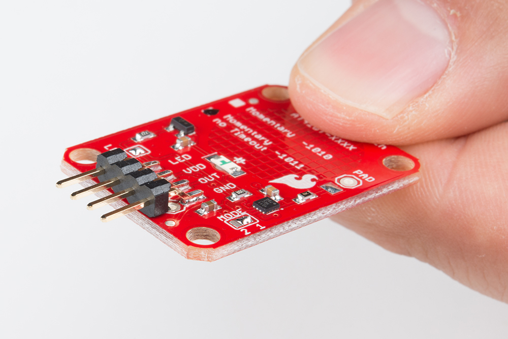
https://cdn.sparkfun.com/assets/learn_tutorials/7/2/2/Capacitive_Touch_Breakout_...
yep, probably will end up using a simple smd header.
shame really, I'd really liked a latched/polarized connector so to make it mefoolproof
knotty tiger
the connector on the Pi isn't keyed, is it?
craggy plank
I don't believe the pictures on the website are accurate, they just have generic pictures, but don't show the number of pins.
bright thistle
knotty tiger
the connector on the Pi isn't keyed, is it?
no, pi has bare 2x20 header
woven bluff
2-row 2.54mm you can always use IDC
worldly schooner

Totaling 560 pieces, this JST-XH Connector Kit is a must-have for your workstation. You'll have enough sockets and headers to fuel your maker tendencies for days on ...
bright thistle
craggy plank
<@263394624888897537> https://www.molex.com/molex/search/deepSearch?pQuery=q%253...
yes, the problem is the other side of the connector XD
craggy plank
bright thistle
yes, the problem is the other side of the connector XD
AH! Yeah, I'm getting a little confused as to which side we're talking about here, haha.
woven bluff
phoenix contact also have 2.54mm screw terminal if you are desperate
craggy plank
@bright thistle Here's the header! https://www.molex.com/molex/products/part-detail/pcb_headers/0705430003
When you said "housing" I thought you were referring to the "crimp housing" haha
worldly schooner
Can't really key the Pi end of the connection, unless you route it out by other means first. https://www.adafruit.com/product/2310

Design your own Pi HAT, attach custom circuitry and otherwise dress your Pi Zero, A+, B+, Pi 2, Pi 3 and Pi 4 (any Pi with a 2x20 connector) with this jaunty prototyping HAT kit.To kick ...
craggy plank
The molex website is great because the product page links to connectors it mates with.
worldly schooner
Haha, sorry, we're all having too much fun with this...
Not any one individual's fault.
bright thistle
nah, it's on me, should've explained myself better 😄
woven bluff
that's why I hate non-standard connectors
worldly schooner
https://www.molex.com/molex/products/part-detail/pcb_headers/0705530003 for non-pegged right angle.
bright thistle
worldly schooner
https://www.molex.com/molex/products/part-detail/pcb_headers/0705530003 for non-...
sadly, is through hole, and I need the SMD (pegged only, afaik), because the button will have to be flush behind plexy, cannot have solder pegs. now...
worldly schooner
You can probably solder to the SMT pads on the back if you're okay with that orientation.
Can't do the same with the vertical headers, unfortunately.
bright thistle
clean slate.
I have the finished board.
I'm currently using SL connectors, and can source the crimp housing for the board side. Heck, Molex has a cable builder!
what I'm missing are:
-
crimp housing "DuPont" style, for the Pi side of the cable
-
if possible, an SMD 2.54 keyed header for the buttons' side. if not possible, I'll just slap a basic header/housing and call it a day
bright thistle
worldly schooner
You can probably solder to the SMT pads on the back if you're okay with that ori...
that's... a way to do it, indeed
worldly schooner
Adafruit Industries, Unique & fun DIY electronics and kits : - Tools Gift Certificates Arduino Cables Sensors LEDs Books Breakout Boards Power EL Wire/Tape/Panel Components & Parts LCDs & Displays Wearables Prototyping Raspberry Pi Wireless Young Engineers 3D printing NeoPixels Kits & Projects Robotics & CNC Accessories Cosplay/Costuming Hallow...
knotty tiger
yeah that's what i was alluding to earlier
and get some of https://www.adafruit.com/?q=raw+jumper&sort=BestMatch , cut off one end, crimp on SL terminations
Adafruit Industries, Unique & fun DIY electronics and kits : - Tools Gift Certificates Arduino Cables Sensors LEDs Books Breakout Boards Power EL Wire/Tape/Panel Components & Parts LCDs & Displays Wearables Prototyping Raspberry Pi Wireless Young Engineers 3D printing NeoPixels Kits & Projects Robotics & CNC Accessories Cosplay/Costuming Hallow...
craggy plank
1) crimp housing "DuPont" style, for the Pi side of the cable
https://www.mouser.com/ProductDetail/HARTING/09185406813?qs=GZB%2FOSW0r0G7wPxAoQA0Lw%3D%3D There we go
Alternatives:
https://www.mouser.com/ProductDetail/3M-Electronic-Solutions-Division/3417-6600?qs=QV10cN0MjFtvWrDHVBQaiA%3D%3D
@bright thistle
bright thistle
worldly schooner
https://www.molex.com/molex/products/part-detail/pcb_headers/0705530003 for non-...
ok, I'm going with this one for the buttons 🙂
and make an according cable. WCS, I'll just have to switch wires' positions in the housing
knotty tiger
if it's only 5 wires, i would use a 40-position housing (or smaller, if you're not fussy about possible misalignment) and only populate the used positions, instead of the added friction and stress of a full 40-pin IDC
worldly schooner
Dupont kits aren't that much more expensive, if you want to go with your own hookup wire. I personally like Adafruit's approach for smaller quantites, but https://www.amazon.com/Dupont-Connector-Kit-Connectors-Plusivo/dp/B078RRPRQZ if you're interested in the other route.

Dupont Connector Kit - 1004pcs Crimp Connector Kit with 2.54 mm Crimp Pin Connector Housings, Single Row Male Headers, Male/Female Crimp Pins and Ribbon Cable from Plusivo
knotty tiger
is this a one-off, or are you going to be manufacturing?
bright thistle
knotty tiger
is this a one-off, or are you going to be manufacturing?
nah, one-off.
I'll be sharing the results, tho 🙂
worldly schooner
You could also use the permaproto hat and route your desired pins to a combination of your preferred connectors as well, but I think your PCB has you covered...
bright thistle
worldly schooner
You could also use the permaproto hat and route your desired pins to a combinati...
yep, it bundles whatever pins I need them to be 🙂
namely, power
knotty tiger
i prefer custom wiring harnesses to adapter PCBs if done neatly. less bulky
bright thistle
btw, I just dared to connect the board to my laptop, and nothing blew up.
so either I have an open circuit, or it works as intended XD
unique patio
stray bridge
Thank you very much! That was the missing component in this!
We created the repo now with the Eagle files: https://github.com/adafruit/Adafruit-Infineon-Trust-M-PCB
distant raven
unique patio
We created the repo now with the Eagle files: <https://github.com/adafruit/Adafr...
ya know, I never considered this as a valuable breakout until just now. I might just have to get one to play around with. probably be a cool addition to any IoT project
stray bridge
distant raven
ya know, I never considered this as a valuable breakout until just now. I might ...
It’s quite a fantastic chip. It can generate a 2048 bit rsa keypair internally, store it, and then act as a crypto bastion, and it uses mbedtls to secure the wire. It also has a trng and can generate a sharedKey for another pubkey on another trust-m chip.
Then you can use the shared key for authentication, pass the other side an encrypted message with that shared key, verify that it is the same as yours, and you know you are indeed talking to the correct MCU and can use the shared key to setup further crypto to pass data without ever having exchanged key materials.
stray bridge
unique patio
We created the repo now with the Eagle files: <https://github.com/adafruit/Adafr...
You guys are amazing!
I am working on a project where I need to “marry” two MCU’s together, and took some hints fro the automotive industry. I looked at the Infineon products as well as the Maxim 1Wire devices, which look rather amazing, as the entire device has two pins, and uses voltage pulses on the power pin as a data line, so the device can almost be attached to an mcu by adding nothing more than one Gpio pad and ground. The Maxim chips didn’t have a dev board though, so I started with the trust-m and it is a very, very useful device.
It can run crypto faster than any MCU can from what I can tell, and the key materials never leave the chip, meaning the MCU is not the important part to protect, and since it guards the wire protocol as well, decaping the trust-m board and going at the silicon is really the only way to get the key materials out of it.
distant raven
That’s pretty neat
stray bridge
The general idea is you send data that can only ever be read by one, singular MCU, so if someone were to sniff the wire while also breaking the wire guarding encryption, they would be presented with data that requires heavy capital investment to acquire plain text from. 2048 bit RSA is nothing to scoff at hahah. The automotive industry does this all the time, BMW marries their PMC (Powertrain Management Controller) to things like the throttle body and the sensor network on the engine, that’s why the dealerships have to wire up the car to a computer when those parts fail.
distant raven
Yeah, makes sense
stray bridge
I did manage to trim a lot of space on a breakout for this chip, though.

I’m pretty sure eagle is trying hard to tell me I need more space around those bits, but I have a feeling they are fine.
distant raven
Just change your clearance between pads
I think 0.15mm between pads is doable
Which is ~6 mil
stray bridge
It was done with defaults, I’d never used the software until two days ago, so I’m sure I can squeeze some more out of it.
 distant raven
This was a fun 2 layer design
stray bridge
I bet it was. I’m excited to make a few more designs, it was a really fun experience.
I realized I had the device I needed, it was just way too big, and bam, pcb designer.
knotty tiger
stray bridge
The general idea is you send data that can only ever be read by one, singular MC...
2048 RSA is a bit on the weak side today (only 112 bits of strength)
stray bridge
True, but that still leaves it on the end of needing gigantic piles of cash to break the key.
There are other higher-tier crypto chips, but this is one of the few with an Arduino library that actually works properly.
knotty tiger
i wouldn't use 112-bit strength for protecting anything long-term today
stray bridge
If the plain RSA isn’t enough, you can use RSA to negotiate an AES256 key and use that for your data protection algo.
knotty tiger
it fails forward secrecy if the entire transaction is monitored and the RSA key is broken later
stray bridge
Using the pub key to gen a shared secret, which is not transmitted, and then using that as the pass phrase for the aes session is about all we could reall hope for for 4 dollars.
knotty tiger
Yubikey has supported 3072 and 4096 bit RSA for years (though i think it's closed source)
stray bridge
Let’s be real, though, is anyone going to be issuing a replay attack against a calibrated sensor the chip will be authenticating?
 tawny apex
forward secrecy is only needed if the protected data would be valuable in the future.
stray bridge
I simply need to make sure that probe A can only every be used on machine 7, as they were calibrated to each other and married with a crypto wedding.
knotty tiger
but yeah for stuff like authenticating chips to each other on a vehicle bus, it's probably totally adequate for the life of the device
for being a secure key store for long-term secrets, probably not
stray bridge
The biggest advantage is you can’t get the key material back off the chip, it was created there.
Cloning the chip then becomes a task best suited for an electron microscope.
I believe it also does ecdsa but I haven’t had time to verify that.
knotty tiger
i guess if you fork over enough money you can get the CMVP-certified versions that are guaranteed against certain kinds of physical key extraction attacks
stray bridge
Yeah, exactly.
There are other chips that are using rsa 4096 bit keys and as such are more secure, but the chip itself costs more than an assembled breakout. If I were designing an MCU it would be a much different story, the price would be negated and I could put a big bad boi crypto engine on the board directly. The optiga chips are about the cheapest thing that has a full set of features, on the other hand, and I’d rather have projects with less than cutting-edge deciphering techniques than having nothing, or incorrectly configured key generation. The chip takes the scary bits away from setting up good crypto, even if it isn’t excellent crypto.
woven bluff
DRV8251, DRV8231... all gone
distant raven
Unfortunately the part shortage
woven bluff
cause ?
distant raven
Global parts shortage affects even parts you wouldn’t expect
Covid and supply chain issues over the last two years is the biggest culprit
woven bluff
I found an adafruit 8871 breakout
any idea how do I blow the 8871 off without frying it ?
distant raven
Texas Instruments Texas Instruments DRV8871DDA US$21.9369
LCSC electronic components online Power Management ICs Motor Driver ICs
- leaded datasheet+inventory and pricing
LCSC has them if you’re willing to pay $21 a piece
$15 for the L6201 https://lcsc.com/mobile/product-detail/Motor-Driver-ICs_STMicroelectronics-L6201PSTR_C178265.html
STMicroelectronics STMicroelectronics L6201PSTR US$13.9538
LCSC electronic components online Power Management ICs Motor Driver ICs
- leaded datasheet+inventory and pricing
There’s a few of these DVR8860 https://lcsc.com/mobile/product-detail/Motor-Driver-ICs_Texas-Instruments-DRV8860PWR_C2149500.html
Texas Instruments Texas Instruments DRV8860PWR US$2.9322
LCSC electronic components online Power Management ICs Motor Driver ICs
- leaded datasheet+inventory and pricing
I’m not super knowledgeable on motor drivers though so that might not meet your needs
 ember laurel
yeah motor drivers is close to impossible, unless you go to some chinese scalpers
 broken python
knotty tiger
Yubikey has supported 3072 and 4096 bit RSA for years (though i think it's close...
broken python
knotty tiger
Yubikey has supported 3072 and 4096 bit RSA for years (though i think it's close...
As a Yubikey fan, I had to chime in here - you are correct! Yubikey supported those RSA variants starting with Yubikey 4 series released in 2015. And yes, it's all proprietary / closed source, and with non-upgradable firmware (unfortunately).
woven bluff
I use onlykey
it can store ED25519 NIST256P1 SECP256K1 HMACSHA1
also RSA
and I'd never trust a closed source hardware key
 echo glen
I don't know if you have a space recquirement or no. If no, you can make your h bridge with mosfet
distant raven
Doing that wildly unadvised thing of putting a Bluetooth chip and bits on a flex PCB
2 layers at that
Lol
woven bluff
I have a DRV8871, but it's stuck on an breakout board
broken python
woven bluff
and I'd never trust a closed source hardware key
Once something open source has feature parity, I'll switch. SoloKeys was promising but they backed out of supporting most of the features I cared about.
All independent audits I've read rank Yubico's security the best - even over more open solutions.
distant raven
broken python
Once something open source has feature parity, I'll switch. SoloKeys was promisi...
Yeah, Yubi is the go to for most cybersecurity initiatives in localized security
I had one for my old job
We had 3-4 layers of authentication
Just to log in
broken python
distant raven
Yeah, Yubi is the go to for most cybersecurity initiatives in localized security
I'd love to see competition and backed SoloKeys on their first Kickstarter (not their 2nd one because of the lack of OpenPGP still)
But alas, until then... Yubikey it is for most of my FIDO and OpenPGP needs
distant raven
Yeah
broken python
distant raven
We had 3-4 layers of authentication
Federal Government? IBM?
distant raven
Employer was a Gov contractor
broken python
gotcha, that'll do it
nothing I do professionally requires them, but dang they make some aspects of my personal life rather convenient and/or with peace of mind
teal storm
what is the layer that i put shapes on that means "drill straight through this" in eagle
nvm i have a solution
distant raven
behold, cursed BLE add on for the RP Watchy

on a flex PCB
bottom side

this would never pass FCC testing
or it would be very hard to certify it is what I should say
broken python
Because it's an external antenna? Or is the antenna the darker corner?
distant raven
broken python
Because it's an external antenna? Or is the antenna the darker corner?
Because the entire circuit is on a flex PCB which isn’t great for RF performance
It would take a lot of effort to tune the antenna network to be within an acceptable noise range for certified Bluetooth low energy products
Luckily it’s for personal use and won’t require certification
broken python
distant raven
It would take a lot of effort to tune the antenna network to be within an accept...
could you make just the antenna part non-flexible? or would that not really matter because the ground plane would still be flexible and interfere?
distant raven
It more has to do with the RF characteristics of the PCB as a whole
Many WiFi/Bluetooth or RF related boards are usually a minimum of 4 layers and professionally tuned to have the perfect matching network
Unless your a maker who basically just throws caution to the wind and wings it
Which I am, but I will probably spend some time tuning this antenna down the road
broken python
Ahh gotcha
distant raven
I honestly should apply more engineering finesse to the network since I have an engineering degree wasting away
bright thistle
distant raven
I honestly should apply more engineering finesse to the network since I have an ...
cries in tech foreman diploma
 dry bough
i have a chip-on-board that i want to figure out what it is
i have figured out it is 48 pins under black epoxy. the multimeter is a woods dmmw1 aka kobalt dt-103 aka CEM dt-103.
it doesn't have a crystal, which i think is very interesting
would that mean this very cheap multimeter has a clock built in?
 rigid galleon
Hi all! There's an internal pinout in my Intel NUC board that is female, 2x10 with a 1.25 mm pitch. I'm looking for a male-to-male cable to connect it to my PCB, but I'm struggling to find it anywhere. I've found many similar connectors on Adafruit, but they either have the wrong number of pins, or wrong pitch. Does anyone have an idea on where else to look or find a cable like this?
 dry bough
rigid galleon
Hi all! There's an internal pinout in my Intel NUC board that is female, 2x10 wi...
dry bough
rigid galleon
Hi all! There's an internal pinout in my Intel NUC board that is female, 2x10 wi...
is there an intel nuc spec sheet? it might be a proprietary connector.
rigid galleon
dry bough
is there an intel nuc spec sheet? it might be a proprietary connector.
https://www.intel.com/content/dam/support/us/en/documents/mini-pcs/nuc-kits/NUC8i7HVK_TechProdSpec.pdf
Seems to be mentioned on pages 41 and 44
inland jungle
research suggests a mating part:: DF13-20DS-1.25C
naturally out of stock everywhere
dry bough
sadge

Octopart
Find the best pricing for Hirose DF13-20DS-1.25C by comparing bulk discounts from 5 distributors. Octopart is the world's source for DF13-20DS-1.25C availability, pricing, and technical specs and other electronic parts.

Intel NUC NUC6i7KYK Skull Canyon Internal Common IO Header Dual USB 2.0 Panel Mount
thiss perhaps?
rigid galleon
Looking for the whole wire, so think I’ll go with this one: https://www.chip1stop.com/view/dispDetail/DispDetail?lang=en&cont=USA&partId=HIRO-0002781&utm_medium=cpc&utm_source=google&utm_campaign=G_SSC_America&utm_term=HIRO-000278116897921128&gclid=Cj0KCQjwzqSWBhDPARIsAK38LY-rZXcHJkKg760Vhy-IHQX0A58OYpbaWftTZuVvskkC5_ojhVyHH-4aAsAVEALw_wcB
rigid galleon
dry bough
thiss perhaps?
That’s the correct connector on the one side, but I’m not looking for USB
Thank you @dry bough and @inland jungle, I really appreciate the help 😁
dry bough
idk if this will be any help
I'm trying to figure out what the part number is for the cable connector for the Internal Common IO Header (1.25 mm Pitch). The TPS says "NOTE Connector is Entery part number 3950K-J20C-00L, 1.25 mm pitch header, surface mount, vertical" but this appears to be the board side. Entery's website is not...
interesting, now its not deleting my links :/
confused
rigid galleon
I just realized that the DF13-20DS-1.25C is a 2x15, not 2x10, whoops
rigid galleon
dry bough
https://community.intel.com/t5/Intel-NUCs/Mating-connector-for-Internal-Common-I...
The links here seem to be 404s now
dry bough
Intel NUC NUC6i7KYK Skull Canyon Internal Common IO Header Dual USB 2.0 Panel Mount
that picture looks right, ig you can just cut off the cable if u can't find an alternative
rigid galleon
Found it!
https://a.aliexpress.com/_mP4rCNo

aliexpress.com
Smarter Shopping, Better Living! Aliexpress.com
Someone in the comments even confirmed it, thanks guys!!

 glacial gale
how fast could you clock an average fpga chip in practice? With a proper cooling mechanism attached to it
Enough for a 100s MHz? If I uploaded a gpu core to it or something
 unreal flax
glacial gale
how fast could you clock an average fpga chip in practice? With a proper cooling...
unreal flax
glacial gale
how fast could you clock an average fpga chip in practice? With a proper cooling...
It would depend on what kind of logic it is running. The maximum clock rate will depend on the complexity of what it has to do in each clock.
glacial gale
unreal flax
It would depend on what kind of logic it is running. The maximum clock rate will...
right, so it was mostly number crunching with SIMD and load/stores on F32 and vector data, there would be a minimal bottleneck for data flow in? meaning generally higher clocks?
unreal flax
Yeah, you'd probably be limited by your memory bandwidth in that case, give or take the floating-point math... some FPGAs have DSP blocks to help with that, some won't.
Though if you want to do GPU stuff, you'll generally get better performance from an actual GPU instead of an FPGA of the same size / cost.
 void portal
Guys I'm looking for a smaller version of an inductive sensor like this
https://www.newark.com/crouzet-switch-technologies/imb1805t/inductive-proximity-detector-5mm/dp/74C3206?COM=ref_hackster
I'm not worried about precision or anything, it just have to be small.
Any ideas?
I'm not that into building my own sensing element... but I've found this chip that makes it a bit easier: https://www.ti.com/lit/ds/symlink/ldc0851.pdf?HQS=dis-mous-null-mousermode-dsf-pf-null-wwe&ts=1657459659184&ref_url=https%253A%252F%252Fbr.mouser.com%252F
distant raven
A stainless steel inductive proximity sensor. Very interesting
void portal
distant raven
A stainless steel inductive proximity sensor. Very interesting
dont have to be exactly like that, think "arduinos" inductive sensor
just small
I dont care about precision. They will detect a huge metal mass but I'll work out their proximity if needed.
void portal
distant raven
A stainless steel inductive proximity sensor. Very interesting
But yes I've tested others like this, dont ask me how they tunned it... it just works
distant raven
Hmm, maybe a magnetometer?
Large chunks of steel would affect a magnetometer readings and you could probably calibrate a lookup table based on predetermined sizes of steel
void portal
distant raven
Large chunks of steel would affect a magnetometer readings and you could probabl...
THIS!
 vernal solar
Hi, I want to use second uart on QT Py ESP3S2. Can I repurpose either I2C or SPI pins?
unreal flax
vernal solar
Hi, I want to use second uart on QT Py ESP3S2. Can I repurpose either I2C or SP...
It looks like A0 and A1 have UART1 as a secondary function, but in general you can multiplex peripherals to almost any pin on the ESP32, too.
 distant raven
woven bluff
distant raven
woven bluff
This is the unfortunate world we live in
distant raven
You might try this one I found https://www.digikey.com/en/products/detail/ECS-RTC-3225-5699HS-TR/15203378
Order today, ships today. ECS-RTC-3225-5699HS-TR – Real Time Clock (RTC) IC Clock/Calendar I²C 10-SMD, No Lead from ECS Inc.. Pricing and Availability on millions of electronic components from Digi-Key Electronics.
worldly schooner
I would imagine RTC ICs are fairly common, though the really accurate ones are going to be harder to source. If you can settle for a small amount of RTC drift or compensate for it somehow, it should make for a much easier substitution.
 rustic linden
gonna try kicad again instead of EasyEDA
distant raven
worldly schooner
I would imagine RTC ICs are fairly common, though the really accurate ones are g...
I do feel like the ones from my searches that are out of stock are easier to solder modules. Plenty of the small SMD packages are pretty accurate with fairly low drift. There are some easier to solder tsop packages but they are very expensive, more than $15 a piece
This one doesn’t seem to bad I found this part with the Digi-Key mobile app. https://www.digikey.com/en/products/detail/DS1375T+T&R/5820835
Order today, ships today. DS1375T+T&R – Real Time Clock (RTC) IC Clock/Calendar 16B I²C, 2-Wire Serial 6-WDFN Exposed Pad from Analog Devices Inc./Maxim Integrated. Pricing and Availability on millions of electronic components from Digi-Key Electronics.
rustic linden
they have an app?
rustic linden
that's so neat
rustic linden
apparently DigiKey released their own schematic and diagramming tool with inbuilt BOM manager, and a beta feature that lets you export it to KiCad
Scheme-it is a free online schematic and diagramming tool with a comprehensive electronic symbol library and integrated Digi-Key component catalog. Try Scheme-it today!
worldly schooner
Ooooh, integrated electronic symbol library. That's a big plus.
Worst part of KiCad IMO is importing components or making custom symbols haha
rustic linden
yee, especially since like, 9/10 of the stuff i either own or get for PCBs is on DigiKey
inland jungle
I'm surprised Eagle hasn't made more efforts to reach out and integrate symbols/footprints with chip manufacturers. There's incentive on both sides to make it easier
limpid nest
inland jungle
I'm surprised Eagle hasn't made more efforts to reach out and integrate symbols/...
There's a lot auto desk hasn't done, unfortunately
teal storm
inland jungle
I'm surprised Eagle hasn't made more efforts to reach out and integrate symbols/...
I agree entirely. Eagle is good but it has barely any newer parts. Either you have to make it yourself or find someone who already did. It doesn’t make sense. Also what is Eagle so loud? It’s really annoying sometimes
woven bluff
KiCAD symbols are like at least 10 years old
vernal solar
unreal flax
It looks like A0 and A1 have UART1 as a secondary function, but in general you c...
Thank you @unreal flax . I am already using UART1 with RX and TX pins, tried all remaining pin combinations for UART2, seems not supported 😦
I am trying to use QT Py ESP32-S2 as an I2C responder. It worked as a controller, but not as a responder. Neither Wire nor Wire1 ports. When I am scanning from other device - does not find it but finds other sensors on the same bus. If it is not supported will not harass the device.
glacial gale
unreal flax
Yeah, you'd probably be limited by your memory bandwidth in that case, give or t...
so you would use the DSP to speed up the memory? or the flops?
unreal flax
glacial gale
so you would use the DSP to speed up the memory? or the flops?
The DSP blocks would be for the number-crunching. They'd be faster than equivalent logic made from fabric gates.
glacial gale
oh, maybe one could use them for multiply accumulates or tensor ops. But I do want like the idea to converting the design into an ASIC
 torn plover
how do i make a pcb design with castellated holes to replace an eeprom on a board.
im trying to replace a soldered otp eeprom with a larger flashable (socketed) eeprom. im also integrating bank switching to allow for different rom images
the problem ive got is the original chip is 0.635 mm pitch and i cant find any pinheaders for it so i need to make my pcb have castellated holes to solder it to the main board
 gaunt cedar
has anyone done a custom rp2040 board and loaded their firmware via SWD? I'm running into issues even getting blink.elf to load and I'm not sure why.
openocd error is "Error: RP2040 write: failed to flush flash cache" and "Error: error writing to flash at address 0x10000000 at offset 0x00000000"
gaunt cedar
I believe my issue is lack of external oscillator. anyone know if the simple blink example for the rp2040 could be compiled in a way that tells the board to stick with the internal?
I thought the chip checked itself if there was an external or not
 remote wasp

Does anyone know what is name of the coating for button
And how to remove it efficiently
supple pollen
remote wasp
Does anyone know what is name of the coating for button
It's basically conductive ink. There are different formulations out there, but careful use of the usual solvents (alcohol, acetone, etc.) with a swab might do the job. However, the soldermask and silkscreen are also inks of various sorts, so some solvents will remove them too.
remote wasp
supple pollen
It's basically conductive ink. There are different formulations out there, but ...
Thanks. It helps ✌🏽
supple pollen
The product description for the "Bare Conductive" ink AdaFruit sells states that it can be removed with soap and water, so that's worth a try as well.
remote wasp
Sure will try. Thanks
rustic linden
Never knew how fun it was to make symbols in KiCAD
unreal flax
Whenever you discover something that you think is fun, but other people think is work, then you've possibly discovered a career path in which you have an unfair advantage over everyone else. 😁
 covert blaze
Can someone help me with just saying whether this will work in reality to be able to measure bidirectional current flow, or if it's something that only works in simulation?

As real world schematic

Ignore the Vref VDD having bypass capacitor to another VDD in stead of GND
Lil mistake
worldly schooner
covert blaze
Can someone help me with just saying whether this will work in reality to be abl...
Many current measurement devices use this exact setup to measure current, so I'd be surprised if it didn't work. It's pretty close to TI's actual application circuit: https://www.ti.com/lit/ds/symlink/ina181.pdf
covert blaze
Thanks Hem, can I ask two more questions just to learn abit more
worldly schooner
I believe the 10ohm resistor equivalents are internal to the INA181 IC, if that's what you're using.
Never ask if you can ask, just ask away.
covert blaze
Why is their vref going to another amp?

And, how many of these can I supply with a single Vref IC?
Or is it a Vref IC for each?
worldly schooner
That's a bidirectional application. I believe that the other amp is used as a voltage inverter to reverse the output?
covert blaze
Ah okay, but simply hooking up a Vref to the opamp should make any negative voltage positive if Vref high enough correct?
worldly schooner
You shouldn't have any issues with powering multiple channels with a single power source, as each channel only has a quiescent current of around 260uA. However, if you have an application needing multiple channels, it might be more practical to consider one of the multi-channel chips in the same family, like the INA2181 or INA4181.
covert blaze
I have considered the quad channel one, most didn't due to the recommend layout becoming a bit difficult with how many I need.
 leaden cape
hey im a noob, and i think im confused with the flow of current that happens in my design. with my arduino i want to control a 6amp 12 volt load using a mosfet. i understand i need to connect the powersupply's ground to the arduino's ground to create common ground, i guess by putting the jumper cable between the source pin (connectdd to power supply ground) of the mosfet and the ground hole in the arduino, but wouldn't the 6 amps pump through the arduino too and blow it up?? how do i ground it?
covert blaze
Idea is to have 24 shunt resistor and subsequent measurements.
worldly schooner
covert blaze
Ah okay, but simply hooking up a Vref to the opamp should make any negative volt...
Never mind, that's unity gain. The amplifier is just there to set the reference voltage to be independent of the source impedance of the voltage divider.
covert blaze
worldly schooner
Never mind, that's unity gain. The amplifier is just there to set the reference ...
That sounds like something I can leave out for a smaller BOM yeah?
worldly schooner
covert blaze
That sounds like something I can leave out for a smaller BOM yeah?
Depends on your application. If you expect current flow in both directions, you should be okay with just a simple fixed divider?
covert blaze
fixed divider?
worldly schooner
leaden cape
hey im a noob, and i think im confused with the flow of current that happens in ...
Current only flows from a higher voltage to a lower voltage. Since ground is all one common voltage, no significant amount of current "flows" through your Arduino.
Resistor divider.
leaden cape
worldly schooner
Current only flows from a higher voltage to a lower voltage. Since ground is all...
and connecting my arduino to a transistor make it parallel to the high current load right? so it shouldnt experience the same current?
covert blaze
Sorry Hem, I am indeed still confused
worldly schooner
Shouldn't.
leaden cape
worldly schooner
Current only flows from a higher voltage to a lower voltage. Since ground is all...
and thnx
worldly schooner
covert blaze
Sorry Hem, I am indeed still confused
Do you need bidirectional current sensing?
covert blaze
Yes
worldly schooner
Then you need to feed Vref = VDD/2.
covert blaze
Vref will be 2.5, shunt is set so at max negative current output of -2V output will become +0.5V
Which I can then measure using STM32
worldly schooner
You should be fine to omit the amplifier, but you still need to give Vref 2.5V.
covert blaze
Yeah, will have voltage reference IC on there
worldly schooner
Typical way to do that is to use a resistor divider.
covert blaze
They are pretty cheap
worldly schooner
If you use something else, that's your choice.
covert blaze
Ah
Wait, is there an advantage to using a voltage reference IC
To just diving VDD?
worldly schooner
It's better for fixed voltages, but if you're using an external power source, resistor divider will be more consistently half that, I believe.
covert blaze
Thanks for the explanation and help Hem, always good to end the day knowing more than I did yesterday :D
Now to find a PCB manufacturer which doesn't ask 10 bucks for the boards, but like 70 dollar for the shipping.
worldly schooner
If you go local, you'll probably get the opposite haha
distant raven
worldly schooner
If you go local, you'll probably get the opposite haha
This is why I make tiny PCBs lol..
covert blaze
I'll see if I can make it single sided and just use CNC to cut it maybe
I swear 50% of making PCBs in terms of time is just fiddling with KiCad not wanting to align components
100% sure it's user error though
rustic linden
got into KiCAD today after first not understanding it and switching to EasyEDA for a while
covert blaze
I only used EasyEda so far, second day with KiCad
Having to install an external autorouter is a bit annoying but it works
rustic linden
I'm really enjoying KiCAD now I have some experience with EasyEDA
distant raven
I love the idea of using an m.2 adapter to make expandability. The micromod standard is pretty sweet
covert blaze
I am curious, I often see PCBs with a ton of ground vias everywhere
What does that help with?
Like can I use a bunch of them to separate high current areas from my signal wires?
 distant raven
Impedance control is usually the main motivation
covert blaze
I ended up adding them because they look cool, and maybe it helps with keeping the board cool? Will be running about 0.5 A through it.
distant raven
Especially in analog and by correlation, RF circuits
 signal topaz
covert blaze
I am curious, I often see PCBs with a ton of ground vias everywhere
signal topaz
covert blaze
I am curious, I often see PCBs with a ton of ground vias everywhere
You probably mean the "stitching vias". Those are to stitch multiple ground shapes on different layers to each other. If ground shapes are not properly "grounded", they can resonate and cause problems.
In your case for example this part is not connected to anything, and at some frequency it will act as antenna.

 coral rampart
where can i buy a usb c pinout to make a dock
unreal flax
coral rampart
where can i buy a usb c pinout to make a dock
Do you mean a breakout board? https://www.adafruit.com/product/4090

Throw out all those Mini and Micro B USB cables you have in a plastic bin - the next generation of USB connectors is here with USB C! You will start to see these connectors pop up on all ...
coral rampart
unreal flax
Do you mean a breakout board? https://www.adafruit.com/product/4090
ooh yeah but i need usb 3 which has 5 extra pins i think

eBay
Breadboard compatible with three 4-40 plated mounting holes. USB Type C Male Plug with Impedance matched traces and connector shell access.
looks like the basis of my dock ty for help
coral rampart
oh wait i forgot to include usb pd 3.0 my phone supports 25w
so i think a usb pd breakout with 24 accessible pins may not exist
so i need to make one
or can it hack it together by usbc connecting the breakout board with the pd between that and the device ? prolly not
 pine comet
Hi, I am working on a project using Matrix Portal M4 but need additional storage to store images. I have read that I can connect an SPI to connect to an SD card, but want to know which SPI is compatible with the Matrix Portal and how to connect the two. Thank you
glacial gale

would it make sense to have a more pipelined renderer on a low powered device like pi? Pi 1-3 has a gpu that doesnt look like an average gpgpu with thread blocks and ld/st units. Instead it it seems much more optimised for the usual 3d graphics pipeline?
covert blaze
signal topaz
You probably mean the "stitching vias". Those are to stitch multiple ground shap...
Thank you for the comment, I ended up adding vias to stitch all the ground planes together
rustic linden
will double wide pads be structurally stable enough for soldering female headers 2 across?
a picture for an example

I'm just wondering if the sockets will stay in place and such
limpid nest
are you going to place them in one extreme or the other?
because without that I'd have some concerns tbh
What's driving the need for double wide pads?
inland jungle
if solder completely files in the through 'slots', it should be stable
limpid nest
what are solder eyelets in the context of a circular connector? other options are solder cup, crimp, etc
worldly schooner
limpid nest
what are solder eyelets in the context of a circular connector? other options ar...
IIRC solder eyelets, at least in this context, are basically metal tabs with holes?
rustic linden
This is what I'm planning on putting in the slots
 rustic linden
limpid nest
What's driving the need for double wide pads?
rustic linden
limpid nest
What's driving the need for double wide pads?
to connect both rows of the sockets
limpid nest
Why not just connect them with a trace?
rustic linden
oh, because doing it with multiple rows of pads complicated either in schematic or PCB, this was the easiest way to do this
limpid nest
hm
bright thistle
Cables arrived!
Also, the jumper for selecting the operating voltage :)


Aaaaand... I'm an idiot.
Instead of five 4-pin connectors, I had a brain fart and ordered two 5-pin instead.
At least they're the correct type (SL 90°)

 honest spire
Hello, I want to build seed counter sensor for planter seed machine. I was thinking to put 8 pairs of IR transmitters and IR receivers in order to detect an obstacle when the seed passes
But I have a problem with finding ultra narrow IR emitter in my case I think I need 3 degrees IR emitter

can you point me in the right direction?
distant raven
Hmm, that might be hard to source
Most counting machines for food based stuff usually uses cameras these days
And a ML model
Which has a pretty low barrier to entry given TinyML
Probably more accurate too
You could probably get going with an ESP32 Camera module

Ever wanted to dabble in face and/or speech recognition? Espressif's ESP-EYE is a miniature ESP32-based development board that combines a digital microphone, ESP32 (of course) with ...
supple pollen
covert blaze
I am curious, I often see PCBs with a ton of ground vias everywhere
They're also used for high currents and to conduct heat
limpid nest
I have some rp 2040 stamps that I want to use. I also want to get back into making my own circuit for an MCU. If I make one board that has layout for both but just leave one unpopulated, will the unpopulated one cause any problems for the populated one?
hushed blade
in general, no. there are some edge cases where high frequency lines with dangling traces can turn into antenna and weird things can happen. I don't think you're unlikely to run into that with just goofing around though.
limpid nest
Yeah it's a dev board for developing a driver for an I2C LED driver
Nothing really high frequency involved
signal topaz
limpid nest
I have some rp 2040 stamps that I want to use. I also want to get back into maki...
watch out for potential short-circuits with conductors on the opposite side of the "stamp"
limpid nest
Yeah that's a concern I had but a little conformal coating should fix that
honest spire
distant raven
You could probably get going with an ESP32 Camera module
Thanks, I didnt see your response
distant raven
honest spire
Thanks, I didnt see your response
It’s okay, I should have tagged you in my response
teal storm
What does ppm mean with an RTC. From context clues I can infer it’s about clock accuracy but what is the unit and what does it mean exactly
unique patio
teal storm
What does ppm mean with an RTC. From context clues I can infer it’s about clock ...
parts per million. It should be unitless. so if accurate to 38 ppm, one clock second (or hour, or whatever) might be off by 38 millionths of a second (or hour, or whatever). It's just a fraction expressed in a different way, could be a percentage too.
teal storm
Ok thanks for clarifying
 serene herald
This isn't quite hardware design, but I want to modify my rpi pico to recover as many GPIOs as I can, assuming I always plug into USB for power can I cut the trace between GP24 and the 2040, then solder in a wire to break that out? Same question for the onboard LED on GP25, can I just desolder the LED or cut the trace and use TP5 or is there a resistor inline somewhere I'd have to dispose of as well?
I really "only" need 27 GPIOs but it would be nice to have another just in case
supple pollen
Seems doable to me.
serene herald
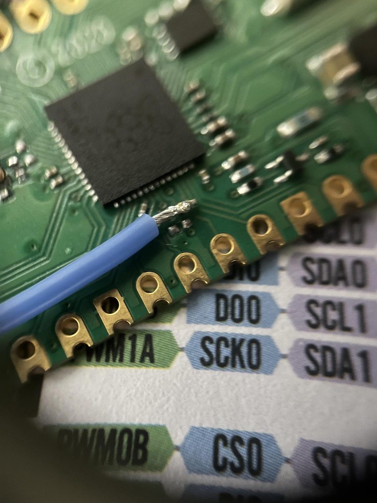
examining the board through a loupe I can see a resistor that comes before the LED, so I could just desolder that resistor and achieve the desired result
serene herald
looks like the LED resistor is 360ohm; the resistor between VBUS and GPIO is 5k6ohm, then the output of that resistor is split off between a 10kohm resistor (connected to ground) and the RP2040 GPIO24 pin - if I desolder both of those I lose VBUS sense and then I should get another input/output - look at section 4.4 figure 14 here: https://datasheets.raspberrypi.com/pico/pico-datasheet.pdf
alright cool, now I just need to perfect my desoldering skills, these are small SMD components!
serene herald
it worked! I was able to switch both of them to input with an internal pulldown and connect them to 3.3 and observe the change in state!
serene herald
I still need to test the output but first I’m going to solder in some short jumper wires so I can actually connect them to a breadboard
distant raven
Nice work
bright thistle
bright thistle
Cables arrived!
Also, the jumper for selecting the operating voltage :)
update: dummy tested the board by plugging it to power source (laptop) selecting both 3v3 and 5v, port still works, so no shorts so far 🥳
I'll have to get my hands on a multimeter, sooner or later...
supple pollen
bright thistle
I'll have to get my hands on a multimeter, sooner or later...
These days, even an inexpensive (US$5) multimeter is pretty useful.
hushed blade
A lot better than not having one, for sure
serene herald
A few photos of my work: https://imgur.com/a/e8Ccs2o
 serene herald
A few photos of my work: https://imgur.com/a/e8Ccs2o
serene herald
serene herald
A few photos of my work: https://imgur.com/a/e8Ccs2o
I took these via my iphone camera through a 10x loupe
 low anchor
Does anyone know any good resources for building custom PCBs? I'm pretty new to the whole process
And soldering them, too? I know you can get solder paste and a stencil but I'm not sure how you'd make the stencil
bright thistle
low anchor
Does anyone know any good resources for building custom PCBs? I'm pretty new to ...
there's plenty of fabs for hobbysts, OSHPark, AISLER (just to name a couple of non-china ones), and IIRC, they provide stencils as well
if you need odd shaped PCB, they'll make them, but will usually bill you to the nearest rectangle that can contain your design
hushed blade
osh park gives you an option at checkout to get a stencil from osh stencils. you can also just order directly from them. it is based off the same files the pcb itself gets made from.
there are a LOT of tutorials out there for kicad, which is the free option. If you know electronics in general, I found the process of learning pcb layout to be pretty straight forward. If you're starting from zero learning electronics, your learning curve will be a lot higher 😉
 rancid lagoon
Kicad is best when you don’t want to make an account that needs everything about you including what shape the cheeto you ate 3 weeks ago was
supple pollen
Or if you're a coder and want to change how it works or see how it does something internally.
 somber marsh
Hey, everyone!
I have a question about the Feather RP2040:
So I designed a keyboard PCB with an 8x10 matrix, one pin dedicated to neopixels, and two pins for i2c, using up the 21 GPIO pins accessible on the board. I also had a rotary encoder, wired into the matrix, and with two pins going to the feather. I realized my mistake after ordering the PCB, and while coding it: the top two rows of the matrix are unconnected. are there any extra pins on the microcontroller I can solder to?
My mind immediately went to desoldering the onboard neopixel... Is there another pin somewhere, and how would I access it both physically and in code?
My backup option is to cut the traces to the rotary encoder, as its function isn't absolutely necessary, and solder wires from the top two rows on the board to the pins on the feather formerly connected to the rotary encoder.
Thanks for any help!
somber marsh
I think the neopixel's power is also connected to a gpio.. How would I access this in code?
Sorry if this is the wrong channel\
 worldly schooner
somber marsh
Hey, everyone!
I have a question about the Feather RP2040:
So I designed a keybo...
worldly schooner
somber marsh
Hey, everyone!
I have a question about the Feather RP2040:
So I designed a keybo...
There are, in fact, unused GPIO on the RP2040 chip, but no way to access them except direct solder to the chip. I don't recommend this unless you're very good at SMT bodging, and would recommend disconnecting the rotary encoder instead if you need all the keys...
You can access the pins by their GPIO number, printed on the underside of the Feather (or in the other pins' case, the schematic linked here: https://learn.adafruit.com/assets/100337)
somber marsh
Thanks! I have an extra feather to sacrifice, so I’ll try my hand at an smt bodge. I’ll aim for gpio5, as it has one unused pin on each side to allow some room for error!
limpid nest
you may need some truly thin wire
bright thistle
distant raven
You need like.. very tiny enamel wire
TIL enamel wire

Magnet wire is copper wire with a thin layer of insulation, and is used in a variety of applications including transformers, wound coils, motors, solenoids, and instruments. Raw copper is drawn to meet specific size requirements based on the National Electrical Manufacturer’s Association (NEMA) s...
supple pollen
Solderable insulation enamel wire like that is very handy for the finer gauges, where mechanical stripping would destroy the wire, and chemical stripping requires special equipment and toxic supplies.
bright thistle
you know what, I'm almost tempted to make my carrier board a sub-assembly, and make it reach another carrier board that would manage the screen as well, so to connect everything to Pi with a 40-pins ribbon
supple pollen
I'm fond of modular approaches (and ribbon cable)
 bright thistle
yep.
in my case, the only change I'd have to implement, is replacing the SL-to-posts cable going to the Pi with an SL-to-SL one going to the new carrier
power wise, it would not be an issue, as it's on a separated source with no risk of back-feeding (the wires to/from Pi are signal only)
as for the overall ribbon usage...
it's one 4-SPI for the screen, five inputs for the buttons, five outputs for the LEDs on the buttons.
should I want to add a Neopixel Ring, I need another GPIO pin (and power it with a dedicated PSU)...
I think I should be able to fit everything?
now, here comes the "fun" part
depending on wether my USB DAC will get recognized by Pi or not, I might need to use a TOSLINK board, thus rendering the GPIO unavailable for other usages.
would i be able to "tandem" a Pico, or Zero, so to leave the "audio" section to main Pi, and everthing else to its sibling?
bright thistle
guess I found a solution myself :3

The MagPi magazine
Access the GPIO pins on a Pi Zero from your PC, or double the available GPIOs on a Pi 3!
bright thistle
uhmmm... maybe I'll have to work as a ethernet gadget, and run a separate script from the secondary Pi, unless luma.oled devs could confirm I could remotely access like in the baove-mentioned method
worldly schooner
bright thistle
now, here comes the "fun" part
depending on wether my USB DAC will get recogniz...
A Pico would probably be better for this purpose compared to the Zero. Less overhead on the RP2040 MCU compared to Pi Zero's Linux will make for a much more robust GPIO expansion solution.
A common division of labor would be to let the Pico handle the buttons and lights, leaving the display and audio to the Pi's dedicated hardware.
bright thistle
worldly schooner
A common division of labor would be to let the Pico handle the buttons and light...
problem is, hifiberry boards do not let usage of the residual GPIOs (easily)
at this point, it might be worth having Pi1 manage the audio part, and Pi2 as eth_g query the mpd on Pi1 to show info on screen and manage buttons
worldly schooner
Oh, you can drive the SPI display with the Pico as well. The Pi's display capabilities are much more powerful thanks to its GPU, but not every project needs an HDMI-size display...
bright thistle
nah, no need for full blown screens, just a simple SSD1322 🙂
but luma.oled doesn't seem to work on Pico 😐
worldly schooner
Ah, yeah. You will have to migrate code for a Pico.
Plenty of display drivers for the Pico, but rewriting code is not trivial...
bright thistle
welp, only one way to make sure I can fit everythin on a connector...
it's battleship header map time!
https://raw.githubusercontent.com/Gadgetoid/Pinout.xyz/master/resources/raspberry-pi-pinout.png
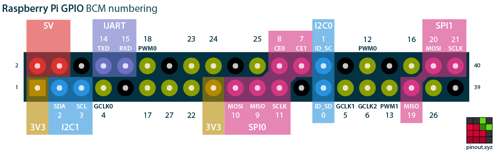
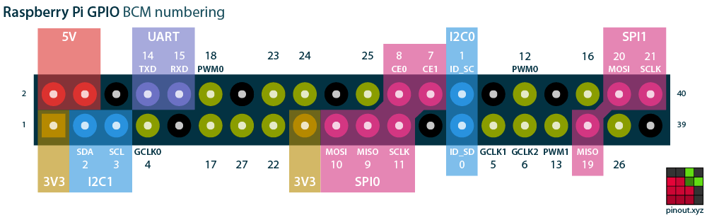
wait. numbering is wrong here?
(edit: linked a correct map)
worldly schooner
bright thistle
wait. numbering is wrong here?
(edit: linked a correct map)
That's weird. I'd stick with https://pinout.xyz/ instead, hasn't failed me yet.
The comprehensive add-on boards & GPIO Pinout guide for the Raspberry Pi
Unless you're specifically using Pi4J like the picture describes.
bright thistle
yep, just printed the map on the bottom of their homepage, will amend my previous line so not to redirect people to a wrong map 🙂
now... supposedly the dsp addon is using the header only as a support and powering, and uses a dedicated connecotr to talk with the main board, so I can ignore its mapping...
GPIO14/15 are normally usable, right? they're not UART by default?
worldly schooner
bright thistle
GPIO14/15 are normally usable, right? they're not UART by default?
By default, they are enabled as UART for a Linux serial console.
I think you can reassign these pins to GPIO at boot, but not sure of the details.
bright thistle
mumbles screeen uses a 2x4 connector... oh!
smart guys... with a single connector, they yoink GPIO24/25 (used for RST and D/C), 3V3, GND, MOSI, MISO, SCLK and CE0!
ok, if I disable UART and give up on NeoPixel, it looks like I have just enough GPIO for buttons and LEDs
but, since I wont be using all the LEDs, only two of the five I have in total, yay!
Ok, assuming there's no conflict, this should be the overall mapping of the pins
 low anchor
Does anybody know where/how I could find a 24-pin ATX power connector part? I'm looking on DigiKey and I'm not able to find it under 'ATX'. Maybe I'm doing it wrong
bright thistle
low anchor
Does anybody know where/how I could find a 24-pin ATX power connector part? I'm ...
Molex Mini-fit Jr 39-01-2240
and pray tell, bot, what's an acceptable linking rate?!
digikey part number WM3711-ND
bright thistle
bright thistle
Ok, assuming there's no conflict, this should be the overall mapping of the pins
found a conflict. PWM channels are all in use by sound card, so I have to give up on Neopixel, at least from the same board
thus, avoiding to use GPIO0/1, and disabling UART, I fit everything just right
 fervent lance
Hi guys, I’m pretty new at circuit board design.
I want a 5V/5A output for a bunch of neopixel LEDs. Can I combine 2 of these the TPS54331 ? They are basic parts and can do 3 amps at 5V.
If so, is there anything I need to be careful about?
Lastly, is there a place where I can find a bunch of reference PCB/schematics for things like this?
bright thistle
fervent lance
Hi guys, I’m pretty new at circuit board design.
I want a 5V/5A output for a b...
Question: given the current, wouldn't you be better using a switching PSU?
(That is, unless your project needs to be moved around)
distant raven
fervent lance
Hi guys, I’m pretty new at circuit board design.
I want a 5V/5A output for a b...
TPS54331 data sheet should have a “Typical Application” section with reference circuits
I found this part with the Digi-Key mobile app. https://www.digikey.com/en/products/detail/TPS5450DDAR/2255288
Try this instead
5A output, 6A peak
fervent lance
bright thistle
Question: given the current, wouldn't you be better using a switching PSU?
(Tha...
This needs to go on a robot, so the power source would be a 7-14v battery
fervent lance
distant raven
Try this instead
I did see that, but it’s $5 a piece instead of $0.40. I would like to try and keep costs down as much as possible
bright thistle
fervent lance
This needs to go on a robot, so the power source would be a 7-14v battery
Ah, got it, nvm :)
fervent lance
distant raven
Where are you getting the TPS54331 for $0.40 a piece?
JLCPCB assembly library has it for $0.40
TPS54331DR from Texas Instruments - DC-DC Converters is available for JLCPCB assembly, check the stock, pricing and datasheet, and let JLCPCB helps you assemble the part TPS54331DR for free.
distant raven
It’s $1.31 on LCSC
For the TPS54540
TPS5450DDAR Texas Instruments US$1.311 - Step-down type SOP-8EP_150mil DC-DC Converters ROHS datasheet, price, inventory C114425
Cost for all the passives for the TPS54540 will be cheaper than using two tps54331
woven bluff
feathers boards do not have pull up at SDA and SCL ?
fervent lance
woven bluff
feathers boards do not have pull up at SDA and SCL ?
The RP2040 board does not appear to have any
woven bluff
nor M4
fervent lance
distant raven
https://lcsc.com/mobile/product-detail/DC-DC-Converters_Texas-Instruments-TPS545...
Awesome, thank you!
woven bluff
there's plenty space on the board
fervent lance
woven bluff
there's plenty space on the board
I believe the resistors get put on the sensor boards themselves
woven bluff
humm, all Sensirion products do not have pull-up
fervent lance
woven bluff
humm, all Sensirion products do not have pull-up
Do the sensirion chips have pull-ups internally? Also maybe the MCU has internal pull-ups
worldly schooner
Which Sensiron product are you looking at?
woven bluff
SEN55
datasheet says need external pull up 10K, I tried on Nano33IoT, which has 4k7 pull-up, 90% of data corrupted
then I added 1K pull-up, it works fine
worldly schooner
If you're using long lines and 3.3v logic, you usually need lower-resistance pullups. Typical shortcoming of I2C.
10K is a fairly standard value for 5V I2C, but for longer connections or lower logic voltages, you will find yourself needing stronger pullup resistors.
worldly schooner
fervent lance
I believe the resistors get put on the sensor boards themselves
Under the stemma/QT standard, breakout boards will come with resistors. This is not such a device, so it does not adhere to the same standard.
unique patio
woven bluff
feathers boards do not have pull up at SDA and SCL ?
It is our general policy to put the pullups on the sensor boards, not the microcontroller boards. The pins may be used for other purposes than I2C so we don't want to hardwire the pullups. Some microcontrollers have internal pullups that would work, but many have relatively high-resistance internal pullups that are not great for I2C.
raw I2C sensors never come with on-chip pullups that I have seen. Instead they are added to the circuit as needed.
fervent lance
I am using Altium to design my board, and I know adafruit using Eagle.
I am trying to add a USB-C connector and I see the Feather RP2040 has CC1 and CC2 both pulled to ground with a 5.1k resistor

The molex connector I found in altium has a different schematic pinout. Would this be correct?

Or is CC1 the same thing as CC2? I'm confused
worldly schooner
fervent lance
The molex connector I found in altium has a different schematic pinout. Would th...
No, that's not correct. CC2 should be pin B5, which would probably show up on J1B.
Page 2 of https://www.molex.com/pdm_docs/sd/1054500101_sd.pdf, for reference.
fervent lance
I see now. Thanks!
This seems like a huge footprint, but other than that, looks good?
 worldly schooner
fervent lance
This seems like a huge footprint, but other than that, looks good?
worldly schooner
fervent lance
This seems like a huge footprint, but other than that, looks good?
Looks good. It does seem like a huge footprint because this one is specifically USB3 compatible. USB2.0 Type C only needs the pins you're using, but a USB3+ will use the other pins for things like DisplayPort...
low anchor
Would it be possible to use a relay that's designed for an AC coil with DC instead? I get they're different but in my head a coil is a coil
bright thistle
low anchor
Would it be possible to use a relay that's designed for an AC coil with DC inste...
somebody already had your question
https://www.ecmweb.com/content/article/20889628/using-ac-coils-on-dc-power
fervent lance
@low anchor I look at the datasheet (and stick with parts that have a known datasheet). It'll say what you can do.
low anchor
Makes sense, thanks
bright thistle
nice, kicad has the Pi port in lib as a handy controller-like symbol

would it be bad, if I were to assign it IDC 2x20 as footprint, instead of pin header, as a part for my board?
I'd like to think as a way to avoid inversion
rancid lagoon
bright thistle
would it be bad, if I were to assign it IDC 2x20 as footprint, instead of pin he...
it will work just make sure pin 1 is in the same spot
woven bluff
is it possible to hot air 8SO PWRPAD off without damaging it ?
rancid lagoon
woven bluff
is it possible to hot air 8SO PWRPAD off without damaging it ?
if you're quick but with the ground plane it might be a challenge
woven bluff
I cannot find any full bridge except those on breakout boards
supple pollen
H bridge? Should be plenty of choices
supple pollen
There's the TI DRV8231 (HSOP-8 with power pad) or the MaxLinear XR8021 (in QFN)
bright thistle
Ok, gonna stop for today, I don't really feel like ratnesting and it shows from the schematic already :|
fervent lance
Hi, Me again. I wasn't satisfied with the last USB-C implementation. I went to JLCPCB and chose a USB-C 2.0 port, downloaded footprint with Ultralibrarian, and placed in my design. the pins are not labeled but based of the schematic, I came up with this:


Can someone double check my work? I really don't want to mess it up
I see that I need to change the 1k to 5.1k
distant raven
I was about to say lol
fervent lance
I forgot to change the values... whooops. Also- any way to make hte resistors smaller in altium?
 languid light
What would this circuit do, assuming that TIDO is a UART RX line for one circuit, and PA5 is the TX line for another?
 fervent lance
distant raven
Like use a smaller part footprint?
fervent lance
distant raven
Like use a smaller part footprint?
yes. I see Phil's lab on Youtube and his resistors always seem smaller
distant raven
Oh yeah, you probably could. I’m not familiar with Altium though. I imagine it’s just a matter of replacing the part with one from the catalog
inland jungle
languid light
What would this circuit do, assuming that TIDO is a UART RX line for one circuit...
looks vaguely like a level translator
 brisk trench
I'm trying to figure out if I can use these p-channel mosfets or if they are the wrong type / rating for what I need...
I have 5v 1.2 amp power source (coming from 5v buck converter) that I want to power my pi pico on the VSYS pin. But if USB is connected, it switches off. From the pico datasheet, I'd do this with a p-channel mosfet with the VBUS connected to the gate so that when power comes in via USB it turns off the secondary power.
I have a FQP27P06 currently. And I'm new to FET's, I was trying to figure out if it will work but not sure how to test it. I tried measuring voltage across S and ground, and it shows constant 5v but I can't get it to "turn off" by applying voltage to the gate, so maybe I'm measuring wrong? I also tried swaping it, putting in 5v to S and measuring from D to ground but I think that is backwards, and it shows 0v no matter what I try.
distant raven
brisk trench
I'm trying to figure out if I can use these p-channel mosfets or if they are the...
Check out the schematic that Adafruit publishes for the feathers. They use a P-Chan mosfet kind of like a switch for powering the device by battery and when both battery and usb are powered
It’s a little more nuanced than just being a switch, but that’s the premise anyway.
low anchor
I'm looking at driving a relay, and the relay needs 24 VAC across the coil, with about 65mA peak current on the relay. If I need to control it using an ESP-32 (which is 3.3v, peak 20mA I think), I think I can use an optoisolator triac. But I'm a bit confused by all of the filters on DigiKey and what different things mean - for example, I don't see a filter for the load voltage or current. Could somebody help me pick a part? Or tell me if it's even possible given the limited output current of the ESP-32?
brisk trench
distant raven
Check out the schematic that Adafruit publishes for the feathers. They use a P-C...
Trying to find it but I'm new to schematics TBH... I found one that seems "high level" so does not include internal stuff on the board. And a BRD file that I can't figure out how to view the schematic from it, in Fusion 360 it gives an error when I try to switch to schematic
unreal flax
A .brd file is only the layout. There would typically be a separate .sch file for the schematic.
distant raven
 brisk trench
yeah there is, looking at it in eagle... I don't see anything that looks like a mosfet symbol (at least not the ones I've seen recently)
distant raven
Had to dig deep in my screenshots to find it
brisk trench
Oh there it is! so DMG321 is the part they use I guess?
distant raven
Or similar
limpid nest
what are the downsides of switching an AC/DC power supply at the AC side?
frequency is many fractions of a hz
supple pollen
languid light
What would this circuit do, assuming that TIDO is a UART RX line for one circuit...
Looks like a combination level translator and inverter
languid light
supple pollen
Looks like a combination level translator and inverter
Ah, thanks. I expected it to be something along those lines because the other line had a similar circuit that I was able to check against internet results.
bright thistle


Ok, managed to solder the header to the buttons, connected them to my board, and they react to touch! No damage done!
brisk trench
Anyone familiar with mosfet's, "how" would I get the one I have to switch off? https://cdn-shop.adafruit.com/datasheets/1794datasheet.pdf

I tried putting voltage from the vbus to the gate but the led stays on
bright thistle
I'd say, S goes to ground, D to the power you want to lose, G to the power that gets priority
If I'm understanding your problem correctly
And put a capacitor between S and gnd
brisk trench
The thing I'm trying to do is figure out how to open / disconnect power going between s and d
this is P-channel, if I understand correctly don't you connect to ground with n-channel?
bright thistle
"resistive switching" in the datasheet seems to be your case
brisk trench
(also in the pic, ignore the wire colors, I was lazy and didn't have spares of the correct size in red / black lol.. (so red != positive necessarily)
supple pollen
brisk trench
this is P-channel, if I understand correctly don't you connect to ground with n-...
For P-channel as for N-channel, connect gate to source to turn it off unless it's a depletion mode device (which I seriously doubt, P-channel depeletion mode MOSFETs basically do not exist).
bright thistle
Not looking neither the cables, nor your picture, tbh.
Rather comparing the schem from skerr and the datash
brisk trench
supple pollen
For P-channel as for N-channel, connect gate to source to turn it off unless it'...
Yeah the goal is it to be on unless a voltage is applied to one of the pins... So I short S and G? And then what pin to I apply the "turn me off" voltage to turn it off?
I found one place saying to make a non depletion FET act like one you short 2 pins but didn't really get how that would have that result...
supple pollen
You connect G to S to turn it off.
bright thistle
Bleah... Transparent PNG. Sorry
supple pollen
However, it looks like you may have it hooked up backwards: the LED appears to be connected to the source, so if drain is hooked to the positive power supply, the parasitic body diode will conduct and current will always flow.
bright thistle
The pic I posted before came from this page
With example circuits and Vgs table for the various types of MOSFETs
brisk trench
wow this is a little freaky lol, I unplugged the power, and have LED properly going to D, and I'm using a static wristband that is grounded... and when I touch the mosfet body the LED comes on slightly
bright thistle
brisk trench
wow this is a little freaky lol, I unplugged the power, and have LED properly go...
Congrats, you became a capacitor, and found out one of the working principles of the theremin antennae!
brisk trench
With the LED going to D and 5v going to S, the LED does not light up
I've connected G to S as well and still no light
also connected 5v to G and no light
never mind I bumped something and it came on
gotta love breadboards sometimes lol
bright thistle
Uhmyeah, try using terminated cables if possible, or solid core wires with a section big enough so to not slip out the board contacts
brisk trench
It was the resistor with it's tiny little leads
anyways, to be continued... dinner time. Thanks for the help so far!
bright thistle
"help" 😂
brisk trench
Imma go with a Schottky diode instead, I have a few already, rated 20v 1amp that should be more than enough to prevent backflow from USB power