#help-with-hw-design
1 messages · Page 60 of 1
 tough matrix
tough matrix
tough matrix
Order today, ships today. TN2106N3-G – N-Channel 60 V 300mA (Tj) 740mW (Tc) Through Hole TO-92-3 from Microchip Technology. Pricing and Availability on millions of electronic components from Digi-Key Electronics.
 limpid nest
Neat thanks! I'll have to pay for rapid shipping TT
limpid nest
I use rosin core leaded solder. When I'm done soldering I use a sprayer of isopropyl alcohol into a bucket (no sink at work, it's a thing) along with a toothbrush to get the Flux off. When I'm done, is the toothbrush contaminated with lead?
 steel valve
I assume this is where I would ask; what is the difference between the NRF52842, NRF51822, and NRF52840
Pretty much, I am making a miniature PCB that wants to be as small as possible while having an analog multiplexer connecting sensors to the nrf module
It'll also have charging capabilities
 unique patio
do you mean nrf52832?
unique patio
steel valve
I assume this is where I would ask; what is the difference between the NRF52842,...
nrf51822 is an older smaller chip, nrf52840 has native USB, nrf52832 does not. Tile and AirTag use nrF52832 I blieve
steel valve
unique patio
nrf51822 is an older smaller chip, nrf52840 has native USB, nrf52832 does not. T...
So the NRF52840 can be programmed by USB, while the others can't, ok
Is there any diff in power consumption?
unique patio
they are all very low
steel valve
So basically not enough to matter
unique patio
nrf52840 can be a USB device, the others don't have native USB, not a big deal for what you want, maybe
steel valve
Right now I utilize the Sparkfun Artemis Nano but its charging speed is way too fast so I am making my own pcb.
Pretty much, it just needs to be programmable via usb, connect to a lipo battery (and charge the lipo too), have usb c, and not use a lot of power.
unique patio
my brother noted the following article just yesterday, which might be an interesting overview. It's about modules,and is a couple of years old, but has some itneresting observations: https://predictabledesigns.com/review-of-bluetooth-low-energy-ble-solutions/
steel valve
unique patio
nrf52840 can be a USB device, the others don't have native USB, not a big deal f...
When you mean a USB device, as in connect to the PC via usb for programming? Or do you mean something different
unique patio
I mean it can be a USB drive, an HID device, etc. General USB device. We use those features for CircuitPython
steel valve
Ah, yeah not intending to use that
Just intending for it to be programmable via Arduino or Segger.
So in that case, I assume the NRF52842 is the best option
Since I don't need to use it for CircuitPython and it has the faster processor, and if I remember right the NRF51822 is BLE 4.0 and the other two are 5.0
unique patio
steel valve
So in that case, I assume the NRF52842 is the best option
yes, I think the '832 is the best choice for this.
we sell '832 dev boards, or you could use the official ones
limpid nest
I'm curious why adafruit went with the pinout they did with the AW9523 board. Bread boarding with it is definitely interesting.
It's not hard but I feel like it could possibly have been easier.
unique patio
it is meant to be compact. I think you might want to put upward facing pins or jacks on the VIN row
limpid nest
Ah I see
Upward facing pins?
My use case is a bit odd, I can't source enough current for the LEDs out of the 3v3 rail on my board so I'm going with a separate PSU
steel valve
unique patio
we sell '832 dev boards, or you could use the official ones
Where are official ones obtained?
unique patio
Order today, ships today. NRF52-DK – nRF52832 series Transceiver; ANT, Bluetooth® Smart 4.x Low Energy (BLE) Evaluation Board from Nordic Semiconductor ASA. Pricing and Availability on millions of electronic components from Digi-Key Electronics.
steel valve
Oh you mean the development kits
Yeah I currently have that
And am moving to the smaller stuff
unique patio
note that the bar chips are in high demand. I only see one version in stock at digikey
steel valve
Yeah
That's my main issue RN is stock issues
Like for example, the 822 is way more available than the 832 and 840
Like mouser has 900 or so of the 822, and then like 4 of the other two
But I don't know how much processing speed I really need for my project since it is pretty simple
Try to send the sensor values as fast as possible
With ~8MS latency as the goal
Oh nice digikey has a crap ton of the 4077 module
(In the case that its a better idea to use the 832)
 marble scaffold
just finished this schematic
this is a pi hat that takes in a 7.4v battery
uses it to power the raspberry pi through a buck regulator, a microcontroller through the pi's 3.3v line, and 2 motor drivers
anything i should revise here?
microcontroller is responsible for giving PWM to the motors
and reading the battery voltage
slightly updated version
 marble scaffold
got a weird issue

everything that's supposed to be ground
is mapping to BATT+
are the nets accidentally connected somehow?

 ember laurel
or an intentional resistive heater, relying on a very long trace for resistance
ember laurel
oh indeed
marble scaffold
now the last issue is that the pin header starts numbering from the right side
 ember laurel
I guess that's just what your footprint is like
tough matrix
marble scaffold
slightly updated version
Shouldn't D1 be Schottky, not Zener? we had talked about it.
Also, I am curious: you connect Pi to samd09 by both i2c and rx/tx. Which of them do you plan to use?
as for numbering of pins in footprint, KiCad has a number of different footprints with different numbering of pins - see if you like any of them better
BTW, do you have a stock of DRV8871? last time I checked, they were out of stock everywhere...
I am doing my own version of 2-channel motor controller right now, but using different driver IC, TLE9201
and last suggestion: do you want to add indicator LED to show power on?
ember laurel
https://lcsc.com/product-detail/DC-DC-Converters_Silergy-Corp-SY8303AAIC_C2937216.html - a bit pricey right now, but still in stock. Small, very efficient.
Silergy Corp Silergy Corp SY8303AAIC US$3.5759
LCSC electronic components online Power Management ICs DC-DC Converters
- leaded datasheet+inventory and pricing
 twilit mango
Bah. Why would EagleCAD not mirror three of the layers when I did select all / mirror group?
(╯°□°)╯︵ ┻━┻
Ends up looking like this instead of everything being mirrored.

Or however many layers it's skipping anyway.
limpid nest
Looks kinda like a screen glitch. I've done stuff like that before
twilit mango
I've tried repeatedly, same issue.
Let me quit and reopen I guess?
Highlight all doesn't seem to be.... highlighting all.
The bits that aren't getting mirrored stay dark when I do CMD+A or use the "group" tool to highlight the whole board.
limpid nest
EAGLE/Fusion have some glaring issues
Makes me wonder why I paid 500 bones for it sometimes
twilit mango
I'm one of Adafruit's seats. But yeah understandable.
limpid nest
It's "worth" it but it's annoying. If KiCad had some kind of killer 3d modeling integration I'd go for it
twilit mango
Sigh. I'll have to ping Limor. I need to flip this board to do the Fritzing object.
Thanks though!
Wait maybe not. Only need to flip the STEMMA connectors...
No, whole board, and then reflip STEMMA connectors. Bleh.
WAIT. I remember a possible reason. Something about locked layers. Hopefully I have notes.
Yes!

Flipped!
There's a lock icon, and if you click it, the top bar has an "unlock all" icon which I clicked. Then when I highlighted all, everything was bright, and everything flipped.
🤦🏻♀️ Was the wrong rev anyway. But hey, at least I remembered the issue.
limpid nest
Wooooo glad you solved it
ember laurel
@limpid nest what kind of 3d modeling do you need integrated?
limpid nest
Mostly 1) STEP quality models of my board and 2) drawing a 2D shape in 3D CAD and making a board profile out of it
The importing of your 3D PCB in Fusion360 parametric is pretty good
ember laurel
hmmm I see
limpid nest
What were you thinking?
marble scaffold
tough matrix
Shouldn't D1 be Schottky, not Zener? we had talked about it.
Also, I am curious:...
yeah this was updated in the schematic, photo i posted was before that
 marble scaffold
tough matrix
as for numbering of pins in footprint, KiCad has a number of different footprint...
marble scaffold
tough matrix
as for numbering of pins in footprint, KiCad has a number of different footprint...
i made a copy of the footprint that had pin ordering mirrored, it's all sorted out
marble scaffold
tough matrix
BTW, do you have a stock of DRV8871? last time I checked, they were out of stock...
https://www.aliexpress.com/item/1005002141174726.html the wonders of aliexpress

aliexpress.com
Smarter Shopping, Better Living! Aliexpress.com
marble scaffold
tough matrix
and last suggestion: do you want to add indicator LED to show power on?
good idea, i'lll add that
update since last i talked here: finished the pcb layout
ember laurel
@marble scaffold now just hope it is not some chinese copy
marble scaffold
yeah
ember laurel
delivery times from aliexpress though...
limpid nest
ember laurel
delivery times from aliexpress though...
Good or bad? I thought they were bad but I've avoided ali
ember laurel
a month if you're lucky
limpid nest
Oof yeah
 supple yew
Are there Kicad parts and footprints for Adafruit specific stuff like the feather connectors and board size?
marble scaffold
marble scaffold
update since last i talked here: finished the pcb layout

i'lll get a better screenshot in a bit
also ik these trace widths are all over the place
i way over built certain sections (ex: the trace for the battery is 70mil!) because i was worried about current draw
and the layout is a bit of a mess too
ember laurel
any reason you have the motor connectors there, and not just close to the motor drivers?
in general, you should try to keep the loop area as short as possible there - because this is your main current part
marble scaffold
ember laurel
any reason you have the motor connectors there, and not just close to the motor ...
don't really have a reason
might redo this pcb to lay it out better
ember laurel
try to put those drivers close to the terminals
and the power input also close
the other chips aren't so important for high power
limpid nest
Also maybe polygons for the motor pins/terminals?
marble scaffold
limpid nest
I think this is easyEDA, not sure if it can do 4+ layer
this is kicad
i can do 4 layer but i want to keep costs down
marble scaffold
ember laurel
<@!740679995269054546> this is only a 2 layer board?
yep
tough matrix
I'd certainly suggest making traces from motor drivers to terminals a lot thicker.
limpid nest
You've got room for that for sure
tough matrix
@marble scaffoldI liked the website placeholder you put there 🙂
 verbal moss
Cheers, looks useful for wide input voltage range, and few additional components needed to integrate.
Thanks @tough matrix, added to my list of potentials for other projects. Need ~2A for current one.
verbal moss
ember laurel
https://lcsc.com/product-detail/DC-DC-Converters_Silergy-Corp-SY8303AAIC_C293721...
Nice find, thanks @ember laurel. Pricey, but it's small and efficient, and in stock!
Update... Looks like DROK and similar use https://www.monolithicpower.com/en/mp2315.html. But MPS recommend MP2393 for new designs. Good luck finding available stock that's cheaper than just using these boards.
if need <= 1.2A then consider https://www.adafruit.com/product/4739 (using https://www.monolithicpower.com/en/mpm3610a.html).

This little buck converter based on the MPM3610 is a marvel, taking up to 21V input and providing a 5V output with up to 1.2A current. It's great for supplying power to popular 5V ...
 heavy jasper
For MP2393 - generally I've found MPS's website to have better stock of their products than they have through distributors - at least as long as you don't need more than their general-sale maximum (which they have as being for product development - but for most folks is probably bigger than their production runs)
e.g. MP2393 is availble at $1.65/unit for 1
w/ 5-dollar shipping in 3-4 business days
tough matrix
unfortunately jlcpcb doesn't carry MPS bucks for assembly
heavy jasper
Yes that being the key restriction - for hand-soldering (or consignment to an assembly house that's willing to re-reel it), easily available.
 median wind
Does anyone know where can I find information about turning state diagrams into a flip flop design?
 heavy jasper
I think this is more of a general "projects" question - but in general you need to be able to make a circuit that takes as inputs (current state, any external inputs) and produces output state, then feed "output state" into a flip-flop for storage. A good search term is "sequential logic" and more specifically, synchronous sequential logic.
or in general, textbooks/classes that are introductions to digital design pretty much all talk about this at some point.
 distant raven
Can you implement a turing state machine with TTL logic?
I learned it with fpga
Or easily implement I should say
heavy jasper
Theoretically - absolutely yes
and folks have done CPUs on breadboards with TTL logic
distant raven
Right, storing in registers (which I guess is just a bank of flip flops and tristate buffers)
heavy jasper
in practice - I would personally much prefer to use an FPGA, even for learning - with breadboards/TTL logic and such it's way too easy to accidentally mess up your circuit by bumping it
distant raven
Which is why I said “easily”
limpid nest
heavy jasper
in practice - I would personally much prefer to use an FPGA, even for learning -...
I'm currently replacing a (non breadboard) circuit that changes state if you set your coffee cup down near it
It's wild
distant raven
I liked designing logical circuits with transistors but there was a point where I really could only move forward with a microcontroller or fpga
I even made flip flops and adders with NPN transistors in nand gate ripple adder configuration
Lots of fun if you’ve never done it
limpid nest
You're just trying to make me regret not doing an EE degree more than I already do!
It's working!
distant raven
Lol, I did that outside of my degree because they were not doing enough
SR Latch with NPN transistors

And the 555 off to the side to eventually pulse the SR latch
This is how I learned the practical function of different logical circuits
tough matrix
getting ready to order my 2-channel motor controller from JLCPCB.

If anyone cares to take a look, here is the schematics
distant raven
tough matrix
getting ready to order my 2-channel motor controller from JLCPCB.
RP2040?
Yup, should have just opened the schematic lol
 spice turtle
tough matrix
getting ready to order my 2-channel motor controller from JLCPCB.
spice turtle
tough matrix
getting ready to order my 2-channel motor controller from JLCPCB.
Do your encoders have external pull ups?
Might want to add pull up resistors on board just in case
(and just dont populate them if you are using an optical encoder)
in my experience, using a RC filter doesnt really work that well, but using pull up resistors of say 10k, work pretty well if you are edge detecting
tough matrix
thanks
normally the magnetic encoders I've seen do have built-in pullups, but indeed, I may add it as an option
bigger problem is that my board only provides 3.3v to encoders, and some need more than that.
but I don't want to add another level shifter...
 thick willow
Can we trust datasheets or do some companies lie about it?
Sometimes I find some pretty inexpensive chinese components, but I'm always wondering if their quality could be lower or something. I usually try to stick to components of big reputable companies, but I'm wondering if I should begin using chinese stuff
 cinder anchor
Are there any reliable ways of testing the components to make sure they meet spec and are reliable? You know, like the IKEA robot arm pushing the rocking chair down, repeatedly 100k times. 😄
thick willow
That's not the kind of route I would like to take. Testing failure modes would be extremely slow and expensive too
cinder anchor
So, I guess then it just comes down to what you consider to be an acceptable failure rate. When you say: "Chinese stuff" are you implying that what you're buying from the "big reputable companies" isn't made in China?
thick willow
No, just talking about chinese companies , as opposed to western/japanese companies that just use chinese workforce.
cinder anchor
Well, most of the components will be made in China, anyway... I think the only difference is the level of quality assurance and support. I order things off of AliExpress all the time, and so far I have received very few components that were not as advertised.
cinder anchor
thick willow
No, just talking about chinese companies , as opposed to western/japanese compan...
What type of components are you buying, if you don't mind me asking?
thick willow
isolated dc/dc converters
cinder anchor
Hmm. I would say buy a smaller batch first, then check them out, and if they are comparable to what you'd get from a trusted seller, order more.
heavy jasper
For the most part… if there is an actual data sheet, and it’s provided by/matches the actual manufacturer and part number of what you’re buying (that is - it’s not someone trying to pass off a counterfeit), then generally the specs on the data sheet are fairly reliable. It then becomes about knowing which specs might be important but not listed (and as such uncontrolled).
I would really really not trust things like bare ICs (that is - I try to only trust first-party sales by the manufacturer, or sales through authorized distributors of parts that are known in-date.), but assembled modules at least have some modicum of effort put into them.
cinder anchor
Harry to the rescue.
heavy jasper
And you can kind of do a bit of an informal failure analysis- say I have thousands of $ of equipment that I want to power by this dc-dc - then I might shell out the extra money for the confidence and peace of mind.
Where the top of that food chain is risk of bodily harm or death to you or anyone else (say…. medical devices) - there even the manufacturer’s word isn’t necessarily good enough and it’s time to start combing through their third-party testing / certifications.
thick willow
That makes sense. I'm currently just prototyping, so I guess I'll just use inexpensive stuff that i find in ali/ebay. But as soon I decide to design the final version I'll stick to reputable sellers like digikey or mouser.
heavy jasper
The best gut sense I have is generally the classic “if it’s too good to be true” pricing.
thick willow
I still was wondering if some companies would outright lie in their datasheet. I figured that if some are willing to spend quite a bit of effort in counterfeiting ICs, lying in the datasheet figures wouldn't be a big deal at all
heavy jasper
There’s outright fraud - e.g. counterfeiting chips - but much much more common is lies by omission and/or just not assigning specs to things.
e.g. for a power supply, your DC voltage might be good but it has absolutely horrendous AC noise and ripple.
Usually in such cases - the figures of merit are just not specified, which means there’s nothing you can take back and say “this product doesn’t meet your specs, I want a refund.”
thick willow
yeah...
well its good to know that we can trust the values
I've seen lot of ppl not being very honest when doing science (p-hacking, arbitrarily discarding data that doesn't support the hypothesis, etc) that I figured that here they could also do that kind of stuff to get the values a little better than what they actually are
another question: are there any risks that isolated parts of a PCB might charge up and develop a voltage that might arc the isolated parts?
heavy jasper
Not impossible, but hard to give better guidance without more info - generally with the regulators on their own won’t do that, at worst you might get some AC voltage /noise coupling between the halves (most commonly due to inter-winding capacitance in the transformer windings not having an AC return path), or maybe some DC but it’s not backed by a ton of energy - when you start adding bigger ground loops is where there can sometimes be interesting times.
cinder anchor
thick willow
I've seen lot of ppl not being very honest when doing science (p-hacking, arbitr...
thanks for summing up the entire pharma industry so neatly 😉
thick willow
Why would there be ground loops if grounds are isolated?
heavy jasper
The same AC coupling business - not quite a ground loop in the true sense, but interesting /weird coupling paths.
thick willow
I was thinking more in some external source that could charge up the isolated parts like atmospheric charges?
heavy jasper
ESD is kind of the canonical one there
thick willow
So I was wondering if connecting both grounds through a high impedance path would make sense or would be just stupid
thick willow
cinder anchor
thanks for summing up the entire pharma industry so neatly 😉
I was refering more to the academia, you know "publish or perish"
heavy jasper
You can - and it’s good to have pads for on a PCB (also to have pads for some high-voltage capacitors across the planes in case you run into said noise coupling problems and need an AC return path)
In the end this kind of comes down to what’s acceptable for you given your intended use of an isolated converter - e.g. do you know you’re going to have a fixed ground offset between the sides, that sort of things.
thick willow
I see... I'm currently just trying to isolate a computer USB from voltages that could damage it if currents decide to take the wrong path
Plan is to power the isolated part from the USB VBUS as well instead of requiring a separate power source
I was checking Analog ADUN ICs, but their solutions end up requiring lots of ICs and passive components, their solutions are expensive and take quite a bit of valued PCB real estate. Then I found some very integrated isolated dc-dc modules that were also very inexpensive. So I figured that they might be a better alternative. I'm not really sure what advantages these Analog complex solutions would give, except higher flexibility.
spice turtle
tough matrix
bigger problem is that my board only provides 3.3v to encoders, and some need mo...
Depends if you are making it universal or for yourself. But even if it gets 3.3V, your pull ups will do the job of translating the levels anyway.
 digital rock
I am trying to design a board with all through hole components and I’d like to replace this board https://www.adafruit.com/product/4654. The key with this board is the true disconnect to provide battery saving mode. I can find the smd chip but that doesn’t help. Can anyone help with a path to explore to design the boost circuit with a true disconnect functionality ?
digital rock
Would something like this work? https://www.digikey.com/en/products/detail/analog-devices-inc-maxim-integrated/MAX608EPA/2115843
Order today, ships today. MAX608EPA+ – Boost Regulator Positive Output Step-Up - DC-DC Controller IC 8-PDIP from Analog Devices Inc./Maxim Integrated. Pricing and Availability on millions of electronic components from Digi-Key Electronics.
heavy jasper
The “true disconnect” tends to just be another power switch that prevents the output of the boost from connecting to its downstream load - you can just make a normal boost circuit, then add a load switch after it.
digital rock
Ty that gives me a thread to explore
limpid nest
I need to switch 8 signals at the same time, is there such a thing as a N-Channel FET (or other transistor) array where all the transistors share a gate/base?
ah there it is, I assumed it would be harder to find
limpid nest
I feel like I'm losing my mind. I have +3v3 in one power rail and GND in the GND rail on the opposite side of the breadboard. When I put a my meter across 3v3/gnd with the black probe at one end of the BB, I read +3v3. But when the black probe touches another part of the BB's GND rail, I get -1.2V. What on earth??
specifically when I touch the ground pin of my unpowered breakout board.
which is tied into the GND rail
3v3 and GND are from an external PSU. That's the only ground point in the "active" part of the circuit
It seems to have something to do with the breakout board that's connected to ground but I don't see how it could.
since the board isn't powered as of yet
I'm a goofus
are opposite ends of a power rail usually not connected on a breadboard?
tough matrix
indeed, long bb are usually split in the middle.
was burned by it too
limpid nest
hmmm
IDK how that could give me a negative voltage but who the heck knows
I swear I've learned this before. I'll probably learn it again
wow this chip I'm using has some major downsides. E.g. LEDs are just on when it's unpowered...
 frigid seal
What's the next step up above LTspice? I'd love to be able to use TI's component models but I can't seem to make LTspice accept them.
 worldly schooner
frigid seal
What's the next step up above LTspice? I'd love to be able to use TI's component...
worldly schooner
frigid seal
What's the next step up above LTspice? I'd love to be able to use TI's component...
https://www.ti.com/design-resources/design-tools-simulation/models-simulators/overview.html
If you're only using TI parts, PSpice for TI might be a nice pickup? There are some limitations if you import third-party models, though?
TI apparently cannot support LTspice directly for some unmentioned legal reasons, apparently.
Other Parts Discussed in Thread: TPS2420 , TPS62177 , TINA-TI , TPS56339 Hi, Can anyone help me get the LTSpice models for the below components, or at least help
 proper anvil
Does it make more sense to add a small chip capacitor to each servo, or to add a single large electrolytic somewhere? trying to prevent brownouts when the servos are moving

 fervent lance
how can I do connectors like those https://ae01.alicdn.com/kf/H25bb4f71ba11462d86b40a612e4731eb4.jpg , flat made out from the pcb with on easyeda?
 verbal moss
proper anvil
Does it make more sense to add a small chip capacitor to each servo, or to add a...
verbal moss
proper anvil
Does it make more sense to add a small chip capacitor to each servo, or to add a...
What servos are you using, how far apart? Answer may depend on your servos and other factors. Seen Capacitor section in https://learn.adafruit.com/16-channel-pwm-servo-driver?view=all , they recommend n * 100uF per servo, but that guidance probably assumes SG90 or something else not too large is being used. PCA9685 16 channel breakouts usually come with a single 1000uF cap, personally have had good experience with those (48 SG90 servos moving in sync. Not sure if that will hold true for my 192 servo build), hth.

Adafruit Learning System
Learn how to connect and program the 16-channel 12-bit PWM/Servo Driver with Arduino, Python or CircuitPython
 tame sigil
fervent lance
how can I do connectors like those https://ae01.alicdn.com/kf/H25bb4f71ba11462d8...
tame sigil
fervent lance
how can I do connectors like those https://ae01.alicdn.com/kf/H25bb4f71ba11462d8...
What do you mean connectors like those?
 unreal flax
tame sigil
What do you mean connectors like those?
unreal flax
tame sigil
What do you mean connectors like those?
Possibly he means card-edge connectors with gold fingers.
tame sigil
fervent lance
how can I do connectors like those https://ae01.alicdn.com/kf/H25bb4f71ba11462d8...
If you mean card edge connectors there are user made libraries for common card edge connector types that you should be able to find.
ember laurel
@thick willow my experience with most Ali/eBay AC/DC PSUs has been pretty bad. 95% of what is on offer is absolute junk, and any CE or FCC markings you’ll find are just markings.
Some are just plain and outright dangerous. If you ever want to take your device to market, and pass electrical safety and EMC tests, you have to use proper supplies from reputable companies.
spice turtle
proper anvil
Does it make more sense to add a small chip capacitor to each servo, or to add a...
If you have the room, use multiple low esr caps to provide for more of a current boost. Otherwise one large, low esr cap should do.
ember laurel
@proper anvil the datasheet for your motor driver says to connect a capacitor to ground for every power supply line.
additionally, it mentions BEMF, and using 10uF ceramic (low ESR) capacitor
not sure if you'll see some bemf
something like this:
https://lcsc.com/product-detail/Multilayer-Ceramic-Capacitors-span-style-background-color-ff0-MLCC-span-SMD-SMT_Samsung-Electro-Mechanics-CL31B106KBHNNNE_C89632.html
Samsung Electro-Mechanics Samsung Electro-Mechanics CL31B106KBHNNNE US$0.0803
LCSC electronic components online Capacitors Multilayer Ceramic Capacitors MLCC - SMD/SMT
- leaded datasheet+inventory and pricing
fervent lance
unreal flax
Possibly he means card-edge connectors with gold fingers.
Yes
tame sigil
there are user made card edge connector libraries for common card edge connector types that you should be able to find.
fervent lance
tame sigil
there are user made card edge connector libraries for common card edge connector...
I'm not trying to use any standard, I'm just trying to learn how to use the software; I'm using easyeda, I'm not finding any way to batch place pins, wires nor other components, googling "easy eda batch placing" or similar keywords ends on nothing
tame sigil
You can select multiple components or pins by left clicking while holding ctrl or shift key at the same time
Havent used easy eda quite a while cant remember exact key
fervent lance
nothing, both do not work, also when I place pins, then delete them, then place other pins, the number does not reset, I mean if I do delete pin 1,2,3 and the place other pins, they will be 4,5,6 and not 1,2,3 ; I'm sorry for asking silly questions, but I'm quite new, and I don't quite know what to even google
limpid nest
If you have a big pour around a pad, 2 Oz is a big heat sink
 noble forum
So, I want to build my own esp32 board, literally just a barebones poc. One of the big things I want to do is add a lipo battery. What are some of the ICs for charge and discharge people recommend.
limpid nest
I'd recommend looking at what the feather line uses
distant raven
Mcp73831
Great single cell LiPo charger
If you want to use multicell packs, I’d have to look but TI makes a few good ones
tough matrix
is it in stock?
spice turtle
looks like only DFNs are in stock
 minor niche
noble forum
So, I want to build my own esp32 board, literally just a barebones poc. One of t...
minor niche
noble forum
So, I want to build my own esp32 board, literally just a barebones poc. One of t...
https://github.com/adamalfath/sentsor-core-esp32micro
https://github.com/adamalfath/sentsor-core-esp32dev
check these two for reference
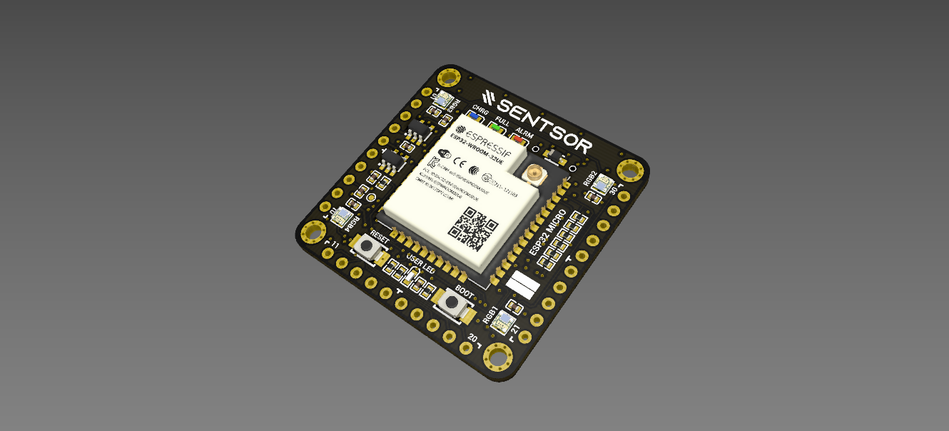
GitHub
Features-rich ESP32 development board in super compact form factor - GitHub - adamalfath/sentsor-core-esp32micro: Features-rich ESP32 development board in super compact form factor

GitHub
General purpose ESP32 development board with onboard RTC & environment sensor - GitHub - adamalfath/sentsor-core-esp32dev: General purpose ESP32 development board with onboard RTC &...
noble forum
Haha. Thank you!
minor niche
the first one is just 30 by 30 mm I think
noble forum
Holy crap. That’s perfect. That’s exactly what I wanted.
The documentation in this is amazing.
minor niche
noble forum
Holy crap. That’s perfect. That’s exactly what I wanted.
hahaha glad it helped
distant raven
tough matrix
is it in stock?
LCSC I believe has the mcp73831
If you order like one or two of these you can get them from Digi-Key
I found this part with the Digi-Key mobile app. https://www.digikey.com/en/products/detail/BQ24170RGYR/5142989
Order today, ships today. BQ24170RGYR – Charger IC Lithium Ion/Polymer 24-VQFN (5.5x3.5) from Texas Instruments. Pricing and Availability on millions of electronic components from Digi-Key Electronics.
It’s for 1-3S LiPo battery packs
It doesn’t show a lead time which usually means stock is hidden to keep people from buying out the whole stock
Sometimes it’s a bug but I’ve found you can still do one or two in an order
limpid nest
Are general circuits questions OK here? I feel like I'm losing my mind
unreal flax
Go for it, probably a good a channel as any.
limpid nest
Ok thx
So I think the outlet is just busted tbh but I might as well confirm here.


I've got continuity between all the contacts on the plug and on the outlet. But when I plug it in, no power
I assume there's an open circuit somewhere in the outlet
I am running a brief errand but I'll check voltage in a second
Only thing that's slightly hinky is the corrosion on the ground lug but that shouldn't prevent current flow
 bright thistle
What's the cable attached to?
@limpid nest
Did you try it in another outlet to be sure the device is not pining for the fjords?
limpid nest
Made the mistake of touching my PSU board. Need a heat sink!
I'm only powering LEDs from it but I guess they are using a good bit of power
distant raven
So a while ago I posted about a photodiode amplifier circuit that I wasn’t getting a response on when polling the analog pin it was feeding. Turns out just one singular pin was not making contact. It wasn’t visible from magnified inspection. I only found out when I accidentally applied pressure to the op amp and suddenly I was getting the kind of input I expected 🙃
Applied more solder to the pins and voilà
So my design was great, I just couldn’t see that a pin was ever so slightly not making contact lol…
limpid nest
ember laurel
<@!887510739462537236> wht requires so much power?
7V regulated to 3.3V powering 32 LEDs
ember laurel
linear reg?
distant raven
limpid nest
7V regulated to 3.3V powering 32 LEDs
What’s the current requirement of the LEDs?
limpid nest
distant raven
What’s the current requirement of the LEDs?
Not 100% sure. I'm testing out AW9523s on a breadboard. I have the LEDs fully "on".
limpid nest
ember laurel
linear reg?
Indeed, meant to say that
ember laurel
if you're using a linear reg to drop 7V to 3.3V, that is quite some drop in voltage, that will go all into heat
limpid nest
Yeah this is just for testing, and only using 7V because that's the barrel jack PSU I had.
I needed to use something greater than 5V for another project. This power unit does 5V and 3.3V
ember laurel
how much current are the leds supposed to pull?
limpid nest
Unclear. I need to dig thru the datasheet and see what current I can expect when the sink is fully turned on
I could stick my meter in series I guess
ember laurel
just measure the voltage drop over the series resistors, and use ohms law?
limpid nest
No series resistors. The chip is a constant current sink
limpid nest
I was thinking of measuring drop and resistance
But I don't know if it's linear?
But if I'm breaking out the meter, I may as well just do an in circuit current test
limpid nest
Yup
ember laurel
that's ohm's second law
limpid nest
Lol
Law 2.5 is check where the probes are in the meter. Ignored that one and I blew a fuse
ember laurel
darn
I was actually just going to write you about that 🙂
because you pull quite some I
limpid nest
Well I was gonna gonna measure one LED and extrapolate
limpid nest
On the meter?
ember laurel
yeah
ember laurel
hmm that thing has a 10 amp limit
limpid nest
I don't think I'm using anywhere near that
limpid nest
These are just basic blinky LEDs, the kind with a 20 mA max
That's what the aw9523 is meant to sink
ember laurel
aha ok
 royal anchor
I plan to design my first pcb. What is a friendly pcb designer software for beginners?
worldly schooner
KiCAD is usually today's go-to for PCB design. I sometimes recommend EasyEDA for its direct part library integration with JLCPCB/LCSC, but KiCAD is probably the first one to consider.
Eagle is the other popular option for its integration with Fusion 360, but it's starting to decline in popularity recently IIRC.
limpid nest
Autodesk is seeingly trying to merge EAGLE into fusion
thick willow
Do computer USB ports have any protection to avoid mains voltage to go through any of their pins?
limpid nest
I don't think so
Not as part of the spec
Some ports on some machines may have reverse voltage protection
Whether that protection can stand up to 120 VRms is another matter
thick willow
I got this https://www.maximintegrated.com/en/products/analog/data-converters/analog-front-end-ics/MAX30001EVSYS.html and couldn't find isolation in the PCB design and also no warning at all about using it only with isolated USB or an unplugged Notebook. So I'm wondering if there is some safety measure that I just missed, or Maxim assumes that the final user doesn't need any warning and will isolate the USB por anyway
The MAX30001 evaluation system (EV system) provides a single platform to evaluate the functionality and features of the MAX30001 with Biopotential (ECG, R-to-R, and Pace Detection) and Bioimpedance (BioZ) measurement capabilities. The EV system includ
Usually when there is risk of electrocution they write some big red warnings.... and considering that electrodes are put directly close to the heart I'm a bit puzzled
ember laurel
@thick willow Medical devices usually require you to have MOPP - Means Of Patient Protection. Depending on the class of device, you'll need 1-3 MOPP.
This, most of the time, is down to the power supply.
I don't think that the evaluation kit is classified as a medical device.
thick willow
Probably, still you would think they should either implement some power isolation or warn about the risks...
ember laurel
they have a small note about "Facilitates IEC 60601-2-47 Compliance Testing"
that standard just references the general standard (60601-1-1) when it comes to electrical hazards

the PSU is considered a part of the medical device
Using an already IEC60601 certified supply helps.
cinder anchor
What's the best, decently priced, PCB service? I looked at SparkFun's A la Carte, but it's a $950 fee. Which would be fantastic if I wanted to mass produce these guys. But, I don't...
Maybe someone could list the recommended vendors and then maybe we can pin that?
I know of PCBWay, JLC, I haven't messed with the Digi-Key service, and didn't Fritzing have some service too?
limpid nest
What's your goal? Hobby stuff as cheap as possible? Places like JLC are your best bet. Best quality:price ratio? Places like OSHPark are better
cinder anchor
limpid nest
What's your goal? Hobby stuff as cheap as possible? Places like JLC are your bes...
It's for a power management system for my truck, so preferably something decently reliable, doesn't need to be super-fancy.
limpid nest
I've always found JLC's quality perfectly fine for my needs, but I'm not make a power management system that's going in a 50k+ truck (assuming). Probably worth the extra 15 bucks for OSHPark
Keep in mind that with these two examples, JLC gives you 5 boards, OSH gives you 3
cinder anchor
I only need 3.
limpid nest
That assumes 100% yield on your manufacturing
cinder anchor
Well, multiples of 3, rather.
limpid nest
You can get multiples of 3 from OSH
cinder anchor
How many would you suggest I get?
worldly schooner
SparkFun's A la Carte is specifically a PCB design service, the other guys usually just fabricate whatever you design.
cinder anchor
6-9?
worldly schooner
Do you have a working design to send out, or are you just doing this for the first time?
cinder anchor
worldly schooner
Do you have a working design to send out, or are you just doing this for the fir...
Oh. You know. First time. I know. I should give up and go home.
cinder anchor
lol
I was waiting for the, hey, you can try, good luck!
So, I have a fairly good idea of what I want on the board, though.
worldly schooner
It might be a good idea to prototype a design if you're uncertain about your design.
Perfboard and wires are a pain, but they do wonders in validating schematics.
cinder anchor
I have already prototyped this with a variety of controllers and different types of "switches" like old school relays and FETs.
worldly schooner
Oh, if you're confident in your schematic, converting to a PCB shouldn't be too bad then.
"Only need 3" means you probably should grab a couple extra, just in case. 5 would be a perfect quantity once you have a design, just in case one or two come out wrong.
cinder anchor
Here's my plan: DC-DC/MPPT control unit goes inside cab along with micro controller and other sensitive parts. Micro controller connects to the custom board in the bed of the truck (inside IP68 enclosure) via a single industrial CAT5 cable (already sourced, and yes, it was expensive) and I was thinking of doing something similar to the Ethernet ports that SparkFun designed for longer runs of Qwiic, and basically control it that way.
There's an example proto breakout from SparkFun that use FETs to switch 12 V power (but from a computer PSU) that I was hoping to adapt to just taking 12 V from the house battery (12 V 100 Ah LiFePo4).
I also found a SparkFun Qwiic GPIO module with 8 ports.
This was before I discovered the amazingness of Adafruit, so most of the stuff I have prototyped with is from SparkFun.
Should I use KiCad for this? What do you recommend?
worldly schooner
KiCad is probably best.
cinder anchor
I would need some pointers on my cobbled together design just to make sure I didn't mess up any resistors/capacitors/whatever diodes or grounds or whatever.
How do y'all feel about this project? Would it be doable by someone like me?
worldly schooner
Don't see why not. You seem to know what you want to do.
cinder anchor
I don't really have enough money to pay someone professional to design it, but I am totally open to sponsoring someone on GitHub in exchange for advice and help with finalizing the board.
worldly schooner
I'm sure someone here can help out in the department of "best practices" after you get a first pass of your design.
cinder anchor
Cool deal. I'll get started (again) on this.
My wife asked me how long the fridge is going to be sitting in the living room and used as a cat perch. I took that as a hint that I should probably finish this project sooner rather than later.
(we're putting a fridge in the truck on slide-out rails)
and then powering with a LiFePo4 battery, and I'm going to add some lights and whatever on there too
I have sourced most of the parts except for components for the board, so hopefully there's still some around 😄
And, I was thinking to outsource the board and all that so that others can build similar setups in their campers/overlanding vehicles.
OK. That was a lot of text. Sorry. I am done now.
KiCad question, Global Symbol Library Table, should I go with the default or is there some Adafruit-specific stuff I should use?
verbal moss
Already ruled out using Adafruit's Perma Proto boards? Have several one off, and v1 projects around the house using those. Only recently decided to invest time/money creating PCB design for compact project that'll have ~20 units. Mainly doing for the fun and experience of being able to rationalize learning how to design a PCB (EasyEDA + jlcpcb + smt assembly).
worldly schooner
verbal moss
Already ruled out using Adafruit's Perma Proto boards? Have several one off, an...
Quoting a previous response, I have already prototyped this with a variety of controllers and different types of "switches" like old school relays and FETs.
cinder anchor
verbal moss
Already ruled out using Adafruit's Perma Proto boards? Have several one off, an...
I have already prototyped it in various configurations in my lab. Now it's time to actually install it in the truck, and I want something that's going to be easy to repair/replace/service.
But, sure, I could cobble something together with perma-proto boards, a few feather splitters, and some bubblegum. 😉
Don't forget toothpicks. Solid McGuyver component.
Wow, KiCad defaulted to A4! It's so nice of it to remind me of my previous home and the simple life of Those That Can SI.
I am hoping I can hand-solder things onto this board. Only thing that worries me a little bit would be the QT connector. Everything else is bulky enough for me to use standard PTH components, and I have enough room in the enclosure (it's like 12"x9") to get away with it, and it probably won't hurt either since some of it is higher voltage/power to have it more spread out.
For 12 V and < 5 A, do I need to use different thickness of vias?
And, if so, how far away from other components do I need to place those?
I don't know anything about electrical interference and whatever, but I am assuming there's going to be some.
cinder anchor
Where can I find the KiCad symbols for these guys?

Or do I have to switch to EAGLE?
From what I can tell that looks like EAGLE, right?
unreal flax
Yes, that looks like Eagle.
 flat vigil
kicad has a CONN 1x4 symbol that I've used for stemma connectors
cinder anchor
I haven't used KiCad before, and I am not even sure how many layers this will need if I design in EAGLE. I can't really afford a subscription, and I don't use the software that often.
I have used EAGLE, and it's pretty cool.
flat vigil
kicad 6 looks awesome
cinder anchor
it does
flat vigil
good time to switch
cinder anchor
oh, snap, I am on 6

@flat vigil can I use the KiCad symbols interchangably with what I'd use in EAGLE? How do I design the PCB with this and the stemma connectors?
Like, footprints and all that.
flat vigil
you can snag symbols out of eagle files but I'd encourage you to use the default kicad library
cinder anchor
yeah, I am using default right now
flat vigil
there are JST SH (iirc) footprints already
so conn 1x4 + jst sh will get you stemma qt
cinder anchor
OK, I will look around and make sure I get the correct one.
flat vigil
just make sure the pin order is right
cinder anchor
What is the correct pin order?
flat vigil
isn't it in your screenshot?
flat vigil
I don't remember off the top of my head
cinder anchor
hahaha, I am a dingus
flat vigil
time for me to get outside. good luck!
cinder anchor
flat vigil
time for me to get outside. good luck!
Thank you!!!!
What does MT mean here?

Is it shielded or something?
limpid nest
I think that's the shield pins
Or what I call shield pins
Take a look at a stemma port, it has two larger "pads" on the sides towards back
I think they are also for mechanical stability
Super easy to rip up traces on a stemma port if those aren't soldered
unreal flax
Probably "mounting" pins.
bright thistle

AISLER Creative Community
Today is a big day! I don’t know if you have already beta-tested our new feature but today we are making it public and real! Starting today, we provide KiCad users with a totally new and greatest experience on the planet to get boards designed in KiCad manufactured. We have developed a KiCad plugin that will speed up the upload big-time. In add...
cinder anchor
OK. I am gonna kick this KiCad symbol editor in the face shortly.
KiCad: I have selected these four rectangles, but, how do I actually change the width of them?

I try to change one of them, and it immediately tries to snap to grid, which makes it either super thin or chonky
Not a huge deal, but it looks kinda ugly without spacing...

Maybe if I remove the numbers and replace them with the text?
meh
cinder anchor
I am looking for the KiCad equivalent of this FET, how do I find it? https://www.sparkfun.com/datasheets/Components/General/RFP30N06LE.pdf
oh, found a symbol that works
cinder anchor
KiCad stuff. This is what I've got so far. I need to somehow add 12 V input voltage from battery and battery negative. Not sure how to wire any of that. PLS SEND HALP.

this would be connected with STEMMA/QT to an Adafruit Feather rp2040.
limpid nest
A 1k resistor is going to make that LED very dim, FYI
Well
3.3mA may be OK but it may end up dimmer than you want
cinder anchor
other than that, how do I map an external 12 V source onto this?
Sources are here: https://github.com/NascentMaker/pwrbox

GitHub
Power Management for 12V vehicle systems. Contribute to NascentMaker/pwrbox development by creating an account on GitHub.
cinder anchor
I basically just want to add terminals for 12 V power
from the house battery in the vehicle
limpid nest
Also whats on the other end of JP1/JP2 et al?
cinder anchor
Ah, those are screw terminals that 12 V accessories are connected to. Like lights and a fridge.
cinder anchor
Yeah, for my truck.
limpid nest
That runs on 12V?
cinder anchor
Yup. It draws less than an amp.
limpid nest
Wow
cinder anchor
Well. It was not cheap. 😄
($700 or so, and that's actually cheap compared to other brands)
limpid nest
So I'm assuming all of them are proper loads and you're not going to create a short thru the fet when you turn it on
cinder anchor
can you explain that a bit further? What does create a short mean?
limpid nest
Like just making sure you have some kind of impedance in the connection between the terminals of JP1 for example. It sounds like you do. Just thinking of mistakes I might have made on my first design.
cinder anchor
Oh. Wait, so if there's nothing connected to those terminals, will it short?
cinder anchor
ok
limpid nest
One note on the layout, advice I've been given is to have a "flow" to your diagram
I like to do board inputs on the left, "thinking" chips/main logic in the middle, and outputs on the right.
Not the only way to do it but it's "logical" to brains from cultures that use left to right writing
cinder anchor
Word. I will try to do something like that once I've gotten this to actually work.
limpid nest
Yeah I sort of assemble as I go and then do cleanups throughout
cinder anchor
I wonder if I can find a TCA9534 chip somewhere?
limpid nest
The fun part is next! Routing!
cinder anchor
Oh my god. I don't think anything routes.
limpid nest
Do you know about octopart?
cinder anchor
I've heard about it by way of searching for things and seeing it in search results. Never actually messed with it.
limpid nest
Good!
cinder anchor
 limpid nest
Lol
cinder anchor
they're $1.59 each... I guess I am getting a bunch, just to be safe
cinder anchor
I already have a hoard of parts.
limpid nest
Lololol
cinder anchor
😄
steel valve
Making a custom PCB and the most important part of it is the power p much.

I have made these two schematic parts based on stuff from adafruit and sparkfun
And my question is, do I need to put anything to link them together
The USB C Charger Charges the Lipo, and the lipo goes into a 3.3v buck converter so that the voltage is always 3.3v since from my understanding in pcb design you should always have a consistent voltage
BTW the T shaped symbols on the left are GND forgot to add the indicator
unreal flax
steel valve
And my question is, do I need to put anything to link them together
Just naming the net "lipo" as you've done should link the two.
steel valve
No no no I don't mean that
I mean is it fine having VBAT Charging Pin 2 (Lipos +) and that same pin going into a step down converter
Buck
^
LiPo
^
Charge
unreal flax
Yes, that should be fine, though you'd want to have your charging current set large enough to both charge the battery and run the downstream circuit.
steel valve
I have it set to 12K (about 80mah)
Anyways cool, so I am doing it right. Does this same concept apply for a fuel gauge?
Pretty much due to the chip shortage I can't seem to find any cheap fuel gauges for lipos that are in stock on mouser/digikey (if you happen to know any please tell me) so I am gonna make an empty area on my PCB to put a fuel gauge when they finally come in stock hopefully one day 😂
limpid nest
steel valve
Pretty much due to the chip shortage I can't seem to find any cheap fuel gauges ...
Try octopart
Just in case
steel valve
I was originally intending to use a chip that is available on adafruit or sparkfun since those usually got a lot of useful info for a student like me but when I look on digikey or mouser they usually aren't in stock
Like on adafruit they use the LC709203F Fuel Gauge, and on Sparkfun they use the MAX17043
cinder anchor
OK, so this part: RFP30N06LE, a MOSFET is no longer manufactured. I am trying to find a comparable part, but I am not entirely sure I've got the right parts.
limpid nest
It's a crapshoot these days
unreal flax
steel valve
Anyways cool, so I am doing it right. Does this same concept apply for a fuel ga...
The fuel gauge should do the right thing so long as the current sensor is placed so that it reads both the charge and the discharge current, i.e. if it's electrically next to the battery.
cinder anchor
How would I formulate that search?
"30A, 60V, ESD Rated, 0.047 Ohm, Logic
Level N-Channel Power MOSFETs"
limpid nest
Make sure you need a power mosfet
How did you arrive at the first choice?
E.g. for your fridge, you don't need 1.8 kW of power
cinder anchor
yeah, true
steel valve
limpid nest
Try octopart
Huh octopart is p nice, found this variant of the adafruit chip they use, but I have zero idea how this is put onto a pcb
limpid nest
Oh yeah
limpid nest
steel valve
https://www.mouser.com/ProductDetail/onsemi/LC709203FXE-05MH?qs=y6ZabgHbY%252BxS...
That's gonna be tough to do with hobbyist tools
steel valve
yeah
ima check the max ones
cause who knows maybe theres a place i didnt check already
f no place with a chip alone of the MAX17043
cinder anchor
limpid nest
E.g. for your fridge, you don't need 1.8 kW of power
so, I am trying to flip this FET switch with 3.3V, what am I looking for as far as the gate charge, drive voltage, vgs, and all that?
cinder anchor
k, makes sense, thanks
limpid nest
Np
cinder anchor
limpid nest
Np
steel valve
Oh yeah, if I were to add an ON/OFF switch to my pcb, where would I make it cut stuff out at?
Inbetween the lipo and the buck?
cinder anchor
I'm mostly making sure that it'll handle switching on/off at temps ranging into like 100'F or so.
steel valve
Or after the buck converts the current to 3.3v
cinder anchor
steel valve
Or after the buck converts the current to 3.3v
before the buck
steel valve
Ok thought so just making sure
unreal flax
steel valve
Inbetween the lipo and the buck?
You could also take advantage of the EN pin on the buck to disable the regulator without needing to have a full disconnect switch.
cinder anchor
What about this one? Would I be able to switch this one with 3.3V or 5V? https://www.digikey.com/en/products/detail/vishay-siliconix/IRFZ34PBF-BE3/13540556
Order today, ships today. IRFZ34PBF-BE3 – N-Channel 60 V 30A (Tc) 88W (Tc) Through Hole TO-220AB from Vishay Siliconix. Pricing and Availability on millions of electronic components from Digi-Key Electronics.
steel valve
unreal flax
You could also take advantage of the EN pin on the buck to disable the regulator...
WDYM without needing a full disconnect switch
unreal flax
steel valve
WDYM without needing a full disconnect switch
Like you wouldn't need to run the main power current through a switch. If you're just flipping the EN pin, it gives you some freedom to use like a tiny DIP switch or something.
steel valve
Oh so I could use a button instead of a switch if I have the button go to EN?
limpid nest
cinder anchor
What about this one? Would I be able to switch this one with 3.3V or 5V? https:/...
I don't think this is a good choice. The threshold should ideally be < 3.3V if you want to use MCU logic to drive it. The threshold is the bare minimum you need to get any current to flow whereas the drive voltage is at minimum rdson
steel valve
That's cool, what footprint do most arduinos that have dip switches use?
limpid nest
limpid nest
I don't think this is a good choice. The threshold should ideally be < 3.3V if y...

Electrical Engineering Stack Exchange
In the attributes of a MOSFET, Digi-Key lists several different voltages. I think I understand what most of them are, but there's one I don't understand: "drive voltage."
Let's take this P-channel
steel valve
Cause I am tryna use parts people typically use in arduinos or similar since its easier to find those types of parts in stock usually
unreal flax
steel valve
Oh so I could use a button instead of a switch if I have the button go to EN?
I think a button versus switch would be kind of independent.
cinder anchor
limpid nest
I don't think this is a good choice. The threshold should ideally be < 3.3V if y...
So, would this one work?
https://www.digikey.com/en/products/detail/vishay-siliconix/IRLZ34PBF-BE3/13540582
Order today, ships today. IRLZ34PBF-BE3 – N-Channel 60 V 30A (Tc) 88W (Tc) Through Hole TO-220AB from Vishay Siliconix. Pricing and Availability on millions of electronic components from Digi-Key Electronics.
limpid nest
Also I'd go with SMD but I'm a glutton for soldering punishment
cinder anchor
I can't solder SMD, brah.
limpid nest
It's not toooo bad
Looks pretty good, you can dump 10 amps down that bad boy at 3.3V V_gs
Might be worth getting heat sinks while you're at it
limpid nest
Oh you want to use that much current?
cinder anchor
no, not really, but I want to make sure I have plenty of overhead
limpid nest
Ah gotcha
cinder anchor
mainly because as far as I understand it, MOSFETs are entirely dependent on ambient temperature when it comes to throughput... Is that correct? So I want to make sure that even in a hot environment (like the stupid south of the US where it's like 100'F) my stuff will still work.
limpid nest
They are heavily influenced by temp yeah
There are often derate curves in datasheets
cinder anchor
thanks
limpid nest
Np!
cinder anchor
OK, order placed.
steel valve
unreal flax
I think a button versus switch would be kind of independent.

So are you saying to do something like this for EN or am I not thinking right on how the button is wired
Whoops meant for LIPO to go to the first part of the button
unreal flax
You no longer have the pullup to the lipo voltage, so that probably won't work. Either have a pullup to lipo and a switch to ground, or a pulldown to ground and a switch to lipo.
steel valve
unreal flax
You no longer have the pullup to the lipo voltage, so that probably won't work. ...
wait is this what you mean im confused
 unreal flax
Time to whip out the old ASCII drawing... LIPO--/ ---+---EN | GND--/\/\--+
With the switch open, the resistor pulls EN down to ground. With the switch closed, EN sees the lipo voltage.
 unreal flax
Nope, that has a direct connection between LIPO and EN, so the resistor and switch won't do anything.
 fiery parcel
So recently I made a prototype of a project im working on... it consists of a CLUE board, an amp+speaker, a little battery charger, and an RFID scanner, all open source from Adafruit. Is this something i'd be able to plunk into a single circuit board design?
(with reasonable effort)
steel valve
unreal flax
Nope, that has a direct connection between LIPO and EN, so the resistor and swit...

Are any of these two what you mean
unreal flax
Can you explain why my diagram is confusing you?
steel valve
What are the slashes
unreal flax
The ---/ --- is the switch, and the --/\/\-- is a squiggly-line resistor symbol.
steel valve
Oh
unreal flax
Sorry for the crappy drawing, heh heh.

 unreal flax
Yep, those are both equivalent, and exactly what I meant.
steel valve
Ok cool
Now, there is one more main thing I can think of RN that I wanna add to my PCB which is a CH340G since I assume it is necessary for programming the Artemis by USB
Are CH340G chips blank?
Do they need stuff loaded onto them before they can do the USB to Serial stuff
unreal flax
They should just be power-up and go.
steel valve
Ok cool so I could just implement one and it would work ok
steel valve
unreal flax
They should just be power-up and go.
Am I thinking this right with how I am wiring it or did I mess up on the VCC VC part
 unreal flax
I'm not familiar with the chip offhand, I'm afraid.
steel valve
Ah ok
This is an example diagram I found of how to wire a CH340E

Which I based my version of the CH340E schematic on
unreal flax
You might want to consult the part datasheet to cross-reference things. Usually they'll have a reference schematic recommended by the manufacturer.
steel valve
What's the purpose of a JTAG connector?
Is it just an alternative to programming via USB?
Is it for loading a core onto a chip assuming it is blank?
unreal flax
steel valve
Is it for loading a core onto a chip assuming it is blank?
It's primarily a low-level debugging interface (halt processor, read registers, step through code, examine variables, etc.), but as part of that it can also do things like loading firmware onto a device even if there is no bootloader code there already.
limpid nest
How do folks handle powering say an itsy bitsy or a feather that they have mounted in a PCB? I need to power both the board and a breakout and another device, all potentially at different voltages.
spice turtle
limpid nest
How do folks handle powering say an itsy bitsy or a feather that they have mount...
Easy. Multiple voltage regulators and a large enough input voltage to accommodate them. Say I have a motor that uses 24V, but the FET drivers need 12-15, but my encoder needs 5V and my mcu uses 3.3V. I would use different regulators for that. In this case, you step off the closest voltage to reduce power draw, so you wouldnt tap off the 24V line to power 3.3V, the power the regulator would have to dissipate would be pretty large even at low current.
opps, I accidentally started Autocad instead of eagle. I was going to show an example

Note: If you are wondering why I didnt use SMPS's for any of the lines its because I had issues with my MCU + a microchip brand SMPS. I solved it by using a linear regulator.
2nd Note, the regulators also show the incorrect part #, on the BOM they are correct.
just little things
tough matrix
limpid nest
How do folks handle powering say an itsy bitsy or a feather that they have mount...
depends on what power source you are using.
If you start with a power source of >=6V (e.g. 2s or 3s LiPo), you normally bring it down to 5V using a buck; then you can feed this 5v to ItsyBitsy/Feather (where it will be regulated to 3.3v by built-in regulator). You can also use your own regulators, as suggested by Nerdz, for other voltages
or you can get a ready-made multi-voltage power distribution board - they are commonly used in drones, e.g. https://usa.banggood.com/Matek-FCHUB-6S-Hub-Power-Distribution-Board-5V-and-10V-BEC-Built-in-184A-Current-Sensor-for-RC-Drone-FPV-Racing-p-1147591.html?rmmds=detail-left-hotproducts&cur_warehouse=CN&trace_id=4a421643999479307

www.banggood.com
Only US$14.99, buy best Matek FCHUB-6S Hub Power Distribution Board 5V & 10V BEC Built-in 184A Current Sensor for RC Drone FPV Racing sale online store at wholesale price.
cinder anchor
I was just about to ask a similar question, ha! If I have a 12 V input source from a battery (100Ah 12V LiFePO4), and I want to feed that into 6 MOSFET N-CH 60V 30A TO220AB, and then out to various 12 V accessories like lights and a fridge, do I need any kind of regulators and the like, if so, what do you recommend?
limpid nest
I phrased poorly. I was thinking how do you deal with reverse voltage or power supplies fighting each other if you want to power the adafruit mcu via a pin? Like someone could plug their laptop in to the MCU and that could be an issue
spice turtle
cinder anchor
I was just about to ask a similar question, ha! If I have a 12 V input source fr...
Im guessing those batteries are regulated already, unless they are actually outputting 14.4VDC (4 in series, assumed 3.6V each), which should be OK to use for other stuff since its rated to take a charge voltage that high anyway.
cinder anchor

SOK Battery
please buy from: https://www.us.sokbattery.com 7 year warranty and maintenance free with a 4000-8000 cycles life span. Detachable cover with replaceable BMS and cells. Connect in series for 24, 36 or 48 volt (maximum) battery bank or connect in parallel for larger capacity. Built-in smart Battery Management System
they have a BMS
spice turtle
limpid nest
I phrased poorly. I was thinking how do you deal with reverse voltage or power s...
Look up an Ideal "OR" gate circuit. You can make one with two shottky diodes or you can use FETs. They make sure only one supply is selected at a time.
limpid nest
Hmm, would have to see if that can be done on the mounting board
spice turtle
There are ideal OR gates out there, and come in SC-70 packages
 empty hollow
Are adafruits internal eagle libraries open source? It would be amazing to have access to those so that making pcb's and intergrating adafruit boards into our own footprints becomes easier.
limpid nest
empty hollow
Are adafruits internal eagle libraries open source? It would be amazing to have ...
You can export the parts from a specific board. It often exports a lot more
empty hollow
Oh wow. Didnt know that was possible. Thank you.
tough matrix
limpid nest
I phrased poorly. I was thinking how do you deal with reverse voltage or power s...
Adafruit feather already has this kind of setup: it can be powered from BAT or USB, and each input is protected from backpowering (USB, by a diode; BAT, by a MOSFET). So for Feather, just connect your 5V power to BAT pin and that's it - no worries
limpid nest
What if someone plugs in a lipo? I'm just trying to think of all failure modes
tough matrix
so you are thinking of dealing with 3 potential ways of powering, LiPo, USB, and external power source? then yes, you need addiitonal protection
for reference, here is a piece of Feather schematics:

see the MBR120 Schottky diode and a FET?
it uses FET rather than diode on VBAT to minimize voltage drop; a diode, even a Schottky, has about 500mV voltage drop (I think - need to double-check)
limpid nest
No I'm just thinking of down the line when I'm not here and someone doesn't read my documentation
Tbf it's their fault if they don't read but if I can doofus proof it...
tough matrix
If you use ItsyBitsy, there is no LiPo connection, so there is less temptation for someone to connect an LiPo
limpid nest
That was my next question, does the itsy have a BAT pin?
tough matrix
There is a BAT pin, which you can use for connecting external power supply
tough matrix
That's ItsyBitsy:

(not sure why they decided to use Schottky and not a FET here. Maybe just because FET is larger?)
tough matrix
yes, diode is more of a voltage drop
limpid nest
Voltage drop across RDSON but with the right fet that's going to be very small
limpid nest
That's not bad
cinder anchor
In the EAGLE schematic editor (9.x), what are the blue Bus lines for?
unreal flax
They allow you to group together multiple nets, so an 8-bit parallel bus would be just one blue line. Individual wires can branch on and off of a bus.
cinder anchor
Also, what kind of terminals do I need to use for 12V and <15A? Can I use the regular screw terminals from the Adafruit site?
cinder anchor
unreal flax
They allow you to group together multiple nets, so an 8-bit parallel bus would b...
Interesting, do you have any examples of this?
I mean, all I've got is an I2C bus over STEMMA/QT.
unreal flax
cinder anchor
Interesting, do you have any examples of this?
A quick example of how to use the Bus function to group nets together in the Cadsoft Eagle electronic design program.
It's not really worth the hassle for an I2C bus, since that's just two signals.
cinder anchor
figured as much, thank you for the link
oh, that is freakin' sweet
but, I obviously don't need it
ember laurel
tough matrix
it uses FET rather than diode on VBAT to minimize voltage drop; a diode, even a ...
In that feather schematics, does VBUS really go right to the gate on the mosfet, without any ESD protection diode for VBUS?
And also without any Pulldown on mosfet gate.
cinder anchor
So. How do you import images for silk screen stuff in EAGLE?
cinder anchor
here's what I have so far, hopefully someone has some spare time and can take a look at these...
tough matrix
ember laurel
In that feather schematics, does VBUS really go right to the gate on the mosfet,...
there is a pulldown on the gate, but no esd protection: https://cdn-learn.adafruit.com/assets/assets/000/057/242/original/arduino_compatibles_schem.png?1531010817

do you think ESD protection could be useful? after all, vbus is nominally only 5v
tough matrix
cinder anchor
here's what I have so far, hopefully someone has some spare time and can take a ...
I'll take a look tonight. But not everyone has Eagle, so it would be better if you also uploaded schematics and view of the board as PDF
ember laurel
@tough matrix well, touch the DC positive pin with your fingers after walking across a carpet, and you might fry the mosfet?
distant raven
ember laurel
<@320665963886280706> well, touch the DC positive pin with your fingers after wa...
Interesting thought. I wonder if anyone accidentally did that..
Just completely nuke being able to use a battery on their feather because they didn’t discharge static electricity before touching their board lol
ember laurel
I just tend to put esd diodes on anything that can be touched by human hands
distant raven
On the other hand, the mosfet Adafruit uses is actually pretty well rated for ESD
ember laurel
You can get up to 5kV or so - which can mess up a lot of stuff
Microcontroller inputs for sure
distant raven
Yeah
tough matrix
ember laurel
I just tend to put esd diodes on anything that can be touched by human hands
can you recommend some esd diodes to use? there are so many to choose from
distant raven
tough matrix
can you recommend some esd diodes to use? there are so many to choose from
Any TVS diode would work in the expected operating voltage range
I found this part with the Digi-Key mobile app. https://www.digikey.com/en/products/detail/DRTR5V0U1SO-7/4457889
cinder anchor
tough matrix
I'll take a look tonight. But not everyone has Eagle, so it would be better if y...
Here's the PDFs, as requested!
Do I need some kind of isolation for the 12 V high power parts? I couldn't figure out how to do that. I actually ended up downloading EAGLE for Linux. While the new KiCad is really, really nice, it doesn't have an auto-router. Something I definitely need because I have no clue what I am doing. As you can tell.
unreal flax
Just to warn you, autorouters pretty much suck until you get into seriously professional tools, so I'd encourage you to climb the manual-layout learning curve.
limpid nest
Yeah autorouter doesn't know what parts not to route close to for example
I've gotten away with auto routing for low power boards but 12V 5A isn't something I'd do with it.
cinder anchor
OK. I feel like I am definitely in over my head here.
limpid nest
Eh you can get there. Just listen to advice and be careful
proper anvil
Okay.. after much deliberation I think I've settled on this design for my PCB wristwatch.. easily my most complex board, and also the smallest, and my first time doing battery management/discrete mcu/LED matrix, so im looking for an idiot-check before I place an order: (There's definitely some form over function going on but im hoping I can get away with it 😆 )
it is an attiny85 and DS2417 RTC to run off a 3.7v lipo, which charges off 5V, and controls 28 LEDs (2-6 are on at once) through two shift registers.
The attiny should be able to detect when +5V is connected, and turn off all the LEDs to keep draw low while the battery charges.
24 of the LEDs are in a matrix, and then the remaining four are individually controlled- I did this because at any given time, 2 LEDs in the matrix will always be on, but 0-4 of the individual ones will be on. I didn't put them all in the same matrix, because I didn't want the LEDs to get dimmer depending on the amount of LEDs on. I can PWM the individual ones to approximately match the matrix ones.
The LEDs will be constant on rather than be triggered by a button press, which is a personal preference of mine, at the expense of battery life.. After some (to be determined) amount of time (when the battery is almost dead) it will enter 'power save', and turn off the LEDs so the RTC can maintain the time setting for a few more hours/days until I get it on the charger. Time setting will be done at the time of programming which is crude but this is a version 1.
ideally programming would be done before installing the attiny, but I added pads to potentially be able to do it (although im not sure if it'll actually work in-circuit)
 verbal moss
Stepper motor PCB... https://www.youtube.com/watch?v=OzqSzFZa2DY
Transparent PCB... https://www.youtube.com/watch?v=3a5fNPUIqAE

My first attempt at making a Stepper PCB Motor!
Get a free trial of Altium Designer - https://carlbugeja.com/altium
My favorite PCB Manufacturer - https://www.pcbway.com
Help me make more projects by supporting me on Patreon - https://www.patreon.com/carlbugeja
My Flexible PCB Actuators - http://flexar.io
You can also support my work by buying...

Happy Transparent Christmas Circuit Trees!!
Get a free trial of Altium Designer - https://carlbugeja.com/altium
My favorite PCB Manufacturer - https://www.pcbway.com
Help me make more projects by supporting me on Patreon - https://www.patreon.com/carlbugeja
My Flexible PCB Actuators - http://flexar.io
You can also support my work by buying mer...
verbal moss
cinder anchor
Do I need some kind of isolation for the 12 V high power parts? I couldn't figur...
@tough matrix thank you for recommending https://www.4pcb.com/trace-width-calculator.html in #general-tech message
The trace width calculator and other info helped me define wider tracks in EasyEDA Design Rules. Helping speed up manual/auto routing. The rules are used by PCB checks as well. My clearances and via sizing is wrong tho.


Access Advanced Circuits' printed circuit board trace width tool. Includes information on how trace width is calculated.
cinder anchor
I'll take a look at this!
cinder anchor
@tough matrix I am playing around with that calculator and from what I can tell, external layers is the way to go because 15 A with a temperature rise of 10 C at 30 C ambient would require 16.4 mm internal traces. 😄 Those are some chonkers.
External Layers In Air gives me 6.29 mm.

Question, though, the light red traces on this board are about 4-4.5 mm wide, but they look like they're covered by something, is that silk screen on top of them?
tough matrix
15A??
that's some serious current for a PCB.
I'd suggest getting thicker copper layers, at least 2oz copper
limpid nest
Also keep in mind that 2oz copper is quite the heat sink
So soldering may become difficult
cinder anchor
tough matrix
15A??
that's some serious current for a PCB.
It's for switching 12 V. At the most it'll probably not use more than 2-3 A per trace...
Realistically speaking. I was trying size up. But, I take it that's not how you do it?
tough matrix
I do use the calculator, but I never worked with more than 5A current, so the idea of 15A on PCB scared me.
but 3A is very reasonable
cinder anchor
I intend to use this in my truck to control power to 12 V things, primarily a fridge and lights. Fridge is rated for 7.5A/3.7A Current DC.
Fridge uses 0.715kw/24h (no load in Max mode running at 0'F).
limpid nest
Where in the truck?
cinder anchor
Bed, on a slide mount.
limpid nest
Make sure you get a very water proof enclosure
cinder anchor
You think IP68 will do it? 😉
cinder anchor
So cables go into enclosure via glands, and yes, then I will have screw terminals inside the enclosure.
I might use a bus bar, too.
limpid nest
If it's intended to be fairly permanent that's a good way to do it
cinder anchor
Yeah, the enclosure will be permanently mounted to the side of the bed on some BuiltRight Industries panels.
Whole bed is also covered with a Retrax Pro XR.
limpid nest
I meant the connections too. Like if you don't intend to disconnect often
cinder anchor
Nope, do not intend to disconnect unless something needs to be repaired.
limpid nest
Noice
cinder anchor
This'll go in a 2020 Ford Ranger SuperCab (long bed). We've got a tent (hard shell) mounted over the bed. It's going to be a sweet camping set up. And, road trip mobile.
I have yet to see several of the more scenic national parks in the US.
But, that's not about PCBs. Sorry.
cinder anchor
I really want to see Yellowstone.
limpid nest
Big Sur too
cinder anchor
There's so many of them. We have a road trip planned on a map, it's going to happen in the next year or two.
limpid nest
You need serious income and or time off to see a major proportion of them
But seeing any is a privilege
cinder anchor
Yeah. I intend to take a couple of months off.
limpid nest
Nice
cinder anchor
So, for this project, how do I isolate the rest of the board from the 12 V stuff?
Or, is that not necessary? I was thinking if there's spikes on the 12 V from the DC-DC charger or MPPT solar charger, I am pretty sure that the DC-DC charger will absorb spikes from the alternator...
And, ESD?
limpid nest
I don't think 12V is enough voltage to arc or break thru the insulation of the PCB
unreal flax
cinder anchor
Question, though, the light red traces on this board are about 4-4.5 mm wide, bu...
Soldermask. Silkscreen is the white ink.
cinder anchor
unreal flax
Soldermask. Silkscreen is the white ink.
Thank you for clarifying! That makes way more sense.
cinder anchor
unreal flax
Soldermask. Silkscreen is the white ink.
so with the soldermask on top, would those traces be considered external/in air?
Or are they internal?
unreal flax
Yes, generally still external. The soldermask doesn't provide much thermal insulation like being inside a PCB sandwich does.
cinder anchor
Cool. So, it looks like those traces would support 5-6 A then with that width.
cinder anchor
Are there any good alternatives to https://componentsearchengine.com/ as far as KiCad imports of symbols/footprints go? For Linux, mind you. For whatever reason these guys wrote the KiCad plugin to only work with Windows. While the EAGLE plugin works for Linux as well.
It's like... We are going to support this super expensive paid product, but, KiCad, which is open source, and completely anchored in Linux, yeah, we're only going to write a plugin in Windows for it.
It's also written in VBS. Hmm. Now I am kind of tempted to reverse-engineer it and create a Linux plugin...
Ick. No. I am not doing that.
cinder anchor
alright, switched back to KiCad. Here's my progress so far.
 fervent lance
nice kicad chops ;)
tough matrix
@ember laurel in continuation of ESD protection discussion, it got me thinking. I have a design of motor controller where I use P-MOSFET for reverse polarity protection:
 ember laurel
Ok?
tough matrix
would you advise me to add ESD protection diodes as well?
power input is expected to be in 5-18V range, typically from a battery
or in this case, since gate is already protected by a Zener, it is not necessary?
ember laurel
ok, that tells you?
tough matrix
that probaly it is not 🙂
ember laurel
🙂
tough matrix
(feeling like a student at an exam)
went looking for a TVS with breakdown voltage in 20+v range...
ember laurel
sounds reasonable
do you expect your input voltage to go above that range?
IE, do you handle back-emf in some way?
tough matrix
not really
ember laurel
I think you should be fine with any ESD diode that's breaking down just anywhere between your VBUS and mosfet absolute max Vds
ember laurel
Shenzhen Jinkaisheng Elec Shenzhen Jinkaisheng Elec SMF24CA US$0.0499
LCSC electronic components online Circuit Protection TVS
- leaded datasheet+inventory and pricing
I think this one will fit your bill
regarding input power to motor driver, I had quite some issues with sparks on the DC input plug, due to a lot of bulk capacitance
(which is of course nice to have for motors, unless you want to make a lot of noise)
I ended up making this to combat it:

my inrush current spike got really high without adding a limiter like this
tough matrix
Thanks! lookign at the datasheet now
tough matrix
cinder anchor
Here's the PDFs, as requested!
Looks good to me, except I am somewhat nervous about traces going between SMD pads of TCA9534 - I'd prefer to avoid it if possible. You have run DRC to verify that all clearances are OK, right?
cinder anchor
tough matrix
Looks good to me, except I am somewhat nervous about traces going between SMD pa...
I did, but I'm not sure it's good. Redoing the entire thing in KiCad and manually laying down traces.
Gotta beef up the traces for the 12V high power stuff anyway.
 supple pollen
ember laurel
my inrush current spike got really high without adding a limiter like this
supple pollen
ember laurel
my inrush current spike got really high without adding a limiter like this
I'm also playing with an inrush current limiter. It ramps up the current over the course of about a second (the steep part on the left), then current limits (the less steep part). This curve is just what I had been hoping for.
 distant raven
supple pollen
I'm also playing with an inrush current limiter. It ramps up the current over t...
distant raven
supple pollen
I'm also playing with an inrush current limiter. It ramps up the current over t...
Oh that’s neat
median wind
I tried labeling my pins in fritzing, but when I mark the negative ones by using ' (for example QA') it appears as "'" instead

ironically "2̅Q̅B̅" displays better, but that's just a crutch I happened to find just now, is there a better way to do this?
@ me if you have a better idea to represent this please 😅
 elder peak
@tough matrix I've been using these guys for that application: https://www.digikey.com/en/products/detail/TJ40S04M3L%2CLXHQ/264-TJ40S04M3LLXHQCT-ND/12352740?itemSeq=355938547
Order today, ships today. TJ40S04M3L,LXHQ – P-Channel 40 V 40A (Ta) 68W (Tc) Surface Mount DPAK+ from Toshiba Semiconductor and Storage. Pricing and Availability on millions of electronic components from Digi-Key Electronics.
It's of course, out of stock and who knows when it'll show up.
ember laurel
@supple pollen here is what I had before the inrush limiter
You notice it a lot more in slow motion 🙂
tough matrix
elder peak
<@!320665963886280706> I've been using these guys for that application: https://...
but it is also sensitive to ESD, so it also would require TVS diode, right?
tough matrix
ember laurel
<@!348911944486486016> here is what I had before the inrush limiter
wow... how much bulk capacitance do you have there??
elder peak
Naw, it has built-in TVS diodes.
tough matrix
elder peak
Naw, it has built-in TVS diodes.
I am confused... the datasheet says "This transistor is sensitive to electrostatic discharge and should be handled with care."
cinder anchor
Can I use vias? Are they OK? Or avoid them?
tough matrix
vias are fine.
(unless if you are doing very high frequency signals, like HDMI )
cinder anchor
Nah, just trying to figure out how to route this GND, and was wondering if it was OK to via it underneath some digital GPIO traces...
limpid nest
Yeah board design of any complexity without vias is nigh on impossible
Some signals can't have them of course
Like shurik said
verbal moss
Do people use 0 Ohm resistors or something else to help tracks crossover (instead of vias) when required to make 1 sided PCB? e.g. required to make Aluminum backed PCB that needs to help shed heat generated by components.
supple pollen
Wire jumpers can work too.
limpid nest
Oof just imagining the hassle of placing those resistors in your schematic!
cinder anchor
Can I get some feedback on this board?
I also have complete KiCad files upon request.
limpid nest
You might consider a 12 position terminal block
Nothing wrong with what you have but 12 position would be more mechanically stable
limpid nest
Typically supply symbols are vertical
 cinder anchor
OK
limpid nest
Gnds are down
cinder anchor
Huh?
limpid nest
Your IC doesn't have any decoupling
cinder anchor
The +3V3 should be vertical, same orientation as the resistors?
limpid nest
Yes
limpid nest
One sec I'm looking at this on mobile
limpid nest
Decoupling capacitors smooth the power into the IC
You can probably get away with a .1 uF but it depends on your power supply
Also I would personally go with 4.7k pull-ups rather than 2.2k
cinder anchor
Why 4.7k? How does that affect things?
limpid nest
It's just a rule of thumb. It's been a while since I looked at the math
cinder anchor
Power supply is a 12 V battery (with BMS) that outputs 12.8 V.
limpid nest
2.2 is probably fine
cinder anchor
k
limpid nest
Where is 3.3V coming from?
cinder anchor
QWIIC connector.
limpid nest
What's the Power supply providing that?
cinder anchor
Which goes to a Feather RP2040.
limpid nest
Ahhh
cinder anchor
Which will be powered by a buck converter, it will be housed inside the cab.
limpid nest
Hmm I'm trying to decide if you should have more than one value of cap for decoupling
Let me pull-up my PC and look at the feather RP2040 3.3v regulator
It's probably a switching regulator so we'll want to take into account the frequency when speccing caps
cinder anchor
ok
Would there be any point in putting some kind of power converter on the board itself?
Oh snap. I forgot one very important thing.
limpid nest
It depends on the power draw of the IC, and transistors. Probably pretty low such that the regulator on the feather can handle it. How far are you running cable between the feather and the board?
cinder anchor
Approximately 9-10 feet. I am going to use these:
https://www.adafruit.com/product/4756

I2C stands for Inter-Integrated-Circuit communications, it's meant for short distances on a PCB or subassembly. But, hey, we're engineers, and we like to push the limits of ...
and do I need one of these? https://www.adafruit.com/product/4903

Sometimes you'll find yourself with an I2C bus controller on one side, and an I2C bus device on the other and you gotta keep em (electrically) separated. Maybe because one is ...
They have mount holes so I am not going to go through the hassle of putting those components on the board itself.
limpid nest
you're likely to have voltage drop over that length
cinder anchor
That's what the active terminator is for
since there will definitely be a voltage drop
anything over like 100 mm is basically not going to work well without the extender
I also have a few of these:
https://www.sparkfun.com/products/16988

The SparkFun QwiicBus EndPoint is the fastest and easiest way to extend the range of your I2C communication bus.
Which might be better?
I've tested them with around 15 feet of CAT5e and they worked fine.
(against a similar set up as the board I posted, but it's a breakout from Sparkfun)
Maybe even put that RJ45 directly on the board instead?
well... hmm, lotta tiny components
one surface mount component is enough for this guy
probably easiest to just mount them next to the board in the enclosure
limpid nest
Hmmm hard to say. I think the active terminator might be best since it doesn't introduce another cable type to the mix
/protocol
cinder anchor
It's just using 4 wires, but over an ethernet cable. Which is way sturdier than a little QT cable
I think the active terminator and the sparkfun component do the exact same thing, basically
and I do have about 20 ft of industrial CAT6e, which was pretty darn expensive, and that's what I was going to use
limpid nest
It's up to you, either will probably work. You can probably find IP rated ethernet pass thrus for your enclosure
cinder anchor
inside a conduit, but also, the cable is shielded, resists oils and all kinds of other crap
I think acids too
lol
it was probably overkill
but, YOLO
limpid nest
The ethernet option doesn't have active termination though, may have voltage drop issues there
cinder anchor
hmm
The breakout uses NXP’s PCA9615 IC, which converts the two default I2C signals into four differential signals, two for SCL and two for SDA. The differential signals are sent over an Ethernet cable, which attaches to the breakout through the on-board RJ-45 connectors. The differential signaling allows the I2C signals to reach distances of up to 100ft. while still maintaining their signal integrity!
That's from the Sparkfun breakout.
limpid nest
Signal integrity, doesn't say anything about the 3.3V line not drooping
cinder anchor
Yeah. You're right.
What about using the 12 V coming into J7 and hooking it up to a buck or similar on the board?
Probably something I can stick a giant heat sink on.
limpid nest
That would work. You could also use the 5V from the feather
Buck that, less heat
and it's OK if it droops a bit
how far are you running again?
cinder anchor
10 feet (approximately) from inside the cab to the back of the bed by the tailgate.
cinder anchor
Yeah... hmm.
The Arduino is going to be inside the cab because it needs to sit near the DC-DC charger so it can tap into the RS-485 modbus crap.
limpid nest
hmm
cinder anchor
The DC-DC charger is not IP-rated, so it needs to be somewhere dry and safe.
limpid nest
tough problem to solve
cinder anchor
I thought about buying Redarc's DC-DC charger which is IP-68 and can withstand like 185'C, but, it's almost $500, and the DC-DC charger I bought from Renogy was like $180.
So, mounting it in the cab is a compromise. Already checked to make sure it'll fit in the little compartment under the rear passenger-side seat.
So, the IC's voltage supply is 1.65V ~ 5.5V. Wouldn't the 3V3 from the RP2040 still work even with the voltage drop over 10 feet of ethernet cable?
limpid nest
Yeah the IC would work, but it's "high" voltage may not be enough to trigger your fets
Or at least turn them on enough to not have a high RDS_ON, and you'd be burning battery power
cinder anchor
hmm
these are the fets I have
so maybe we do need a buck converter on the board to step down from 12 V to 5 V?
limpid nest
to 3.3 surely?
You'll need a 3.3V reference at the very least for your I2C bus
Checkout page 29 https://www.ti.com/lit/ds/symlink/tca9534.pdf?ts=1644188631370
I'd go with a 0.1 uF and and 1 uF cap
I recommend SMD but you have space for thru hole. Just note that the + terminals need to be as close to the VCC pin as possible
cinder anchor
Oh, we need it to be 3V3?
limpid nest
Yeah kinda
You could do mixed signal but it would be more complex
You'd need 2 regulators for one. You need 3.3V for your I2C bus because 5V would damage your feather's GPIO. There are ways to do voltage translation but it's more parts
cinder anchor
OK, so we stick to 3.3V
limpid nest
I would recommend piping your 5V from your feather over and bucking that down to 3.3V
Less heat generated == less power burnt. Esp if you bring in 12V from your battery, you'd just be wasting battery potential on your buck
cinder anchor
from what I can tell, this feather doesn't have a 5V pin?
cinder anchor

A new chip means a new Feather, and the Raspberry Pi RP2040 is no exception. When we saw this chip we thought "this chip is going to be awesome when we give it the Feather ...
limpid nest
how are you powering the feather? USB?
cinder anchor
Probably off of a buck converter.
limpid nest
but like with a USB cable from the buck or feeding power into a pin?
cinder anchor
power into a pin, preferably
limpid nest
Then just pick off that trace for 5V
cinder anchor
I have the feather mounted on this guy:
https://www.adafruit.com/product/2926

The Terminal Block Breakout FeatherWing kit is like the Golden Eagle of prototyping FeatherWings (eg. majestic, powerful, good-looking). To start, you get a nice prototyping area ...
limpid nest
Ah that's a little tougher
Hmm, you could do two wires in one terminal. Kinda janky but it would work
cinder anchor
I mean, it's a proto board too, so I can solder on more screw terminals, no?
limpid nest
I don't see where there's room for that
cinder anchor
yeah, maybe not
I could solder on a jumper cable into the middle and put a 2-terminal in the middle. Pretty sure there's enough clearance under the feather for one of those terminals
basically underneath the rp2040 itself
and there's definitely clearance
limpid nest
Hmm you could use protoboard and a terminal block to make a splitter
cinder anchor
that's what I was thinking
there's protoboard underneath
the ones in the middle are free-floating
limpid nest
Yeah that could work, you could even use solder to get from the USB pin to the terminal block
and GND pins
cinder anchor
word
limpid nest
I was told that 10 uF chip resistors are really a 10, 1, and .1 in parallel but I can't find info on that anywhere. Does anyone know if that's true?
unreal flax
I've never heard that. People often will gang up decoupling capacitors like that in parallel, but it's done as 3 separate components.
limpid nest
Indeed
 azure stirrup
So, I have bought this arduino shield. I was wondering if I can solder sockets onto the prototyping area and attach an I2C device. It needs to connect to PWR, GRND and SDA and SCL
 unique patio
azure stirrup
So, I have bought this arduino shield. I was wondering if I can solder sockets o...
unique patio
azure stirrup
So, I have bought this arduino shield. I was wondering if I can solder sockets o...
certainly. can just solder a small strip of header jack, an then add jumpers to the appropriate pins. It looks like most of the pins on the right have jumper holes for this purpose
azure stirrup
unique patio
certainly. can just solder a small strip of header jack, an then add jumpers to ...
what about 5V and GND can i use the ones in the middle?
unique patio
i think so. I do not see a good diagram of the tie points you can use.
azure stirrup
unique patio
i think so. I do not see a good diagram of the tie points you can use.
what is a tie point?
azure stirrup
ah
unique patio
The picture of the bottom of the board is not helpful

 unique patio
all the holes with a border (ring) around them can be used for jumpers
azure stirrup
perfect thanks
elder peak
limpid nest
I was told that 10 uF chip resistors are really a 10, 1, and .1 in parallel but ...
I'm really hazy on the actual ESR/ESL/et al implications but a 10 uF ceramic chip resistor is better able to do the things that a 10 uF electrolytic resistor can't in terms of frequencies absorbed.
elder peak
limpid nest
I was told that 10 uF chip resistors are really a 10, 1, and .1 in parallel but ...
Also, a 10 uF ceramic MLCC is basically a stack of smol capacitor layers, but not so much like differently valued ceramics in parallel and more like a stack of 0.1mm ceramics.
cinder anchor
I have updated my PCB because the traces I had were super undersized...
here's the KiCad files
I am guessing I've probably missed something important, so any help appreciated!

And yes, I designed (actually bought it on VectorStock for $1) a logo before I even had a working circuit board. Doing the things we're decent at is much faster, and I needed a break from KiCad. 😄
I routed +12V and GND for the MOSFETs on the back.
And crickets... 😦
limpid nest
I'd do a ground pour