#help-with-hw-design
1 messages · Page 53 of 1
 limpid nest
ahhh learned a number of new things today. So for that I would need to make a molex connector?
 worldly schooner
Thankfully, I knew of the MOlex part since I was looking at them recently
No, but that's a more secure option for a semi-permanent connection.
limpid nest
Can I crimp a connector for that housing with a dupont crimp tool?
worldly schooner
Off the top of my head, I have no idea.
limpid nest
ok I can dive into the datasheets
worldly schooner
I would guess no, but I've seen weirder things happen.
I'll go with "unlikely..."
limpid nest
These two seem to go together?
https://www.digikey.com/en/products/detail/te-connectivity-amp-connectors/103958-7/353155
and
https://www.digikey.com/en/products/detail/te-connectivity-amp-connectors/5-103673-7/1122416
?
Order today, ships today. 103958-7 – 8 Position Rectangular Receptacle Connector IDC Gold 22-26 AWG from TE Connectivity AMP Connectors. Pricing and Availability on millions of electronic components from Digi-Key Electronics.
Order today, ships today. 5-103673-7 – Connector Header Through Hole, Right Angle 8 position 0.100" (2.54mm) from TE Connectivity AMP Connectors. Pricing and Availability on millions of electronic components from Digi-Key Electronics.
oops one is discontinued
Order today, ships today. 5-103958-7 – 8 Position Rectangular Receptacle Connector IDC Gold 22-26 AWG from TE Connectivity AMP Connectors. Pricing and Availability on millions of electronic components from Digi-Key Electronics.
worldly schooner
That or any other header in this series, yes. https://www.digikey.com/en/products/filter/rectangular-connectors-headers-male-pins/314?s=N4IgjCBcoBw1oDGUBmBDANgZwKYBoQB7KAbRACYYwAWMABhAF0CAHAFyhAGU2AnASwB2AcxABfAgFpqCEMkjps%2BEADdBqTLgLFIZatToBWJqw6QQ4sWKA
Connectors, Interconnects - Rectangular Connectors - Headers, Male Pins are in stock at Digikey. Order Now! Connectors, Interconnects ship same day
limpid nest
From their educational material it seems that they have crimpable versions? It looks like the ones I posted are supposed to shear off the insulation when you push the wire in?
worldly schooner
The ones you picked are called IDC, which uses ribbon cable to push directly into the "crimps" instead of crimping individual wires.
limpid nest
Ah, so I'd need to buy ribbon cable?
worldly schooner
For that one, yes. If you prefer a housing for crimps, try this one: https://www.digikey.com/en/products/filter/rectangular-connectors-headers-male-pins/314?s=N4IgjCBcoBw1oDGUBmBDANgZwKYBoQB7KAbRACYYwAWMABhAF0CAHAFyhAGU2AnASwB2AcxABfAgFpqCEMkjps%2BEADdBqTLgLFIZatToBWJqw6QQ4sWKA
Connectors, Interconnects - Rectangular Connectors - Headers, Male Pins are in stock at Digikey. Order Now! Connectors, Interconnects ship same day
limpid nest
That's what I was looking at, but don't I need the mating pair?
worldly schooner
Slightly different, yours was IDC for ribbon cable, mine was a housing for individual crimped wires.
limpid nest
ahh
worldly schooner
The mate is the same for both.
limpid nest
these crimps look the same as dupont crimps
worldly schooner
They should be pretty close. If you can get the tabs to line up the same, the Dupont tool should suffice.
limpid nest
I can always try and fail
Are they really $0.19 per? That seems like a LOT https://www.digikey.com/en/products/detail/te-connectivity-amp-connectors/1-104480-2/1125619
Order today, ships today. 1-104480-2 – Socket Contact Gold 22-26 AWG Crimp - from TE Connectivity AMP Connectors. Pricing and Availability on millions of electronic components from Digi-Key Electronics.
worldly schooner
Yeah, TE isn't the cheapest, and usually people buy these in the hundreds or thousands at a time.
Usually you would pick a connector series and just use it for everything you can, get a proper tool for that series, and buy the crimps in bulk.
limpid nest
makes sense. this does seem like a good option to keep people from disconnecting things they don't know how to reconnect
Hmm the crimp tool is 300 dollars. I'm already asking them to spend a ton of money. I'll just use 8x1 duponts and mention it as a potential improvement down the line
 twilit mango
Are Duponts the standard jumper wire connectors?
limpid nest
yup!
worldly schooner
I know some connector series have pre-crimped leads on Digikey.
twilit mango
Because Adafruit sells "pre-crimped" wires. And the black plastic housings for them.
twilit mango
I've used them for a ton of stuff.
worldly schooner
https://www.digikey.com/en/products/detail/molex/0022272081/1130583
https://www.digikey.com/en/products/filter/jumper-wires-pre-crimped-leads/453?s=N4IgjCBcoLQCxVAYygMwIYBsDOBTANCAG4B2aWehA9lANogCscAHAMwgC6hADgC5QgQAXxFA
https://www.digikey.com/en/products/detail/molex/0022012087/171997
Order today, ships today. 0022012087 – 8 Rectangular Connectors - Housings Receptacle White 0.100" (2.54mm) from Molex. Pricing and Availability on millions of electronic components from Digi-Key Electronics.
limpid nest
I can do my own dupont crimping if pressed, it's just not always good quality, so that may be a good choice. I always quip that if anyone needs a true randomness generator they should use the quality of my crimps.
worldly schooner
For a one-off, pre-crimped leads are probably your best friend haha
limpid nest
yeah most likely
twilit mango
Adafruit Industries, Unique & fun DIY electronics and kits : - Tools Gift Certificates Arduino Cables Sensors LEDs Books Breakout Boards Power EL Wire/Tape/Panel Components & Parts LCDs & Displays Wearables Prototyping Raspberry Pi Wireless Young Engineers 3D printing NeoPixels Kits & Projects Robotics & CNC Accessories Cosplay/Costuming Hallow...
worldly schooner
If you have to make a ton of em, consider a tool then.
twilit mango
That's what Adafruit calls them.
limpid nest
let me see if adafruit has them on their digikey store
twilit mango
They absolutely might.
Search by part number is the easiest way to check.
Length isn't customisable though, without soldering wires
But if that doesn't matter, then they're a great option.
limpid nest
I would LOVE a pre-crimped 1x8 female housing with wires, but I don't see that in the adafruit store
twilit mango
Digi-Key might have other ones too. These are the ones I know because Adafruit, obviously.

Are you frustrated by the lack of customization options for your jumper wires? Look no further!Compatible with both male and female wires, these fully customizable wire housings bring DIY to ...
In this pack?
Or am I counting wrong
limpid nest
I have one of those! I don't think you're counting wrong 🙂
twilit mango
No, product description also says 1x8 😄
Anyway, thought I would toss those out there for you.
worldly schooner
I think we passed them after discussing latch locks and friction locks haha
twilit mango
Sounded like you needed something more than that initially, but as you settled it out, it sounded like it might be an option.
worldly schooner
But yeah those are super convenient
twilit mango
I've not crimped my own yet. Haven't needed to because of these.
worldly schooner
There are similar offerings on digikey for other connectors, if you need a more specialized cable
limpid nest
The problem with not using cheap tools is we have properties in other states, so we have to by N*X number of tools, potentially
twilit mango
Digi-Key has All the Things ™️ .
worldly schooner
The set of 3 links I posted above has a friction lock which should hold better if the duponts aren't secure enough.
Pre-crimped and everything.
limpid nest
let me look at those! I got distracted, thanks for tracking them down
twilit mango
Gaffer tape is also super useful to keep Duponts in place.
worldly schooner
It does use its own header though
twilit mango
If you need to stick with cheap and quick.
twilit mango
Hah! 😄
limpid nest
worldly schooner
It does use its own header though
That's the white one? I can solder that to my board no problem
twilit mango
Ok, I'll leave you to it again. Good luck with finding what you need!
limpid nest
Thanks!
limpid nest
worldly schooner
Pre-crimped and everything.
Where are the pre-crimped options? I'm failing to see them 😫
oh my gosh
I see
limpid nest
It seems 150 Ohm is a standard value of resistors per the IEC?
 supple pollen
I don't know about the IEC, but 1.5 is a standard E6 multiplier, so it should be pretty common/standard.
limpid nest
Ok cool, my spec is 130 ohms, but I figured I'd just go to the nearest standard value
This is the part we were discussing earlier this week right? https://www.digikey.com/en/products/detail/texas-instruments/SN7407NSR/1575132 I'm getting close to order-day
Order today, ships today. SN7407NSR – Buffer, Non-Inverting 6 Element 1 Bit per Element Open Collector Output 14-SO from Texas Instruments. Pricing and Availability on millions of electronic components from Digi-Key Electronics.
supple pollen
Yeah, the open collector buffer.
1.3 is an E24 value, so it shouldn't be hard to find a 130Ω resistor either.
limpid nest
Cool. And I'm currently trying to get measurements of my load currents, but some of the relays are busted, can I just use a wing connector to connect the two hot wires together? Additionally, if my max draw is 0.5A (looking likely) would it be safe to use this relay instead? Even with the clip in DIN adapter, it's cheaper https://www.digikey.com/en/products/detail/sensata-crydom/ED24D3R/2665174
Order today, ships today. ED24D3R – Solid State SPST-NO (1 Form A) Module from Sensata-Crydom. Pricing and Availability on millions of electronic components from Digi-Key Electronics.
It's only rated for 3A
supple pollen
That would probably be fine, unless your load has a big turn-on or turn-off spike.
You could probably skip the DIN adapter and just connect to it with Faston type terminals.
limpid nest
let me see if I can find those terminals you're talking about
limpid nest
supple pollen
That would probably be fine, unless your load has a big turn-on or turn-off spik...
I don't think so? The only one that might is 3 motors (can't access so can't give specs) and 2-3 strings of LED christmas lights
supple pollen
Yes. Choose some .187" ones to match the relay terminals and you probably want insulated ones.
limpid nest
what termination would you use?
supple pollen
Something like this, maybe? https://www.digikey.com/en/products/detail/te-connectivity-amp-connectors/3-520276-2/2060928
Order today, ships today. 3-520276-2 – 0.187" (4.75mm) Quick Connect Female 14-16 AWG Crimp Connector Fully Insulated from TE Connectivity AMP Connectors. Pricing and Availability on millions of electronic components from Digi-Key Electronics.
supple pollen
They crimp onto the wires and push on to the relay terminals, you can pull them back off too, if you want to debug or replace a relay or whatever. I find them pretty handy.
limpid nest
ahh that's very nice. How would you mount the relay to some acrylic inside an enclosure?
supple pollen
I'd either sandwich it between a couple of layers with screws, or just hold it down with a zip tie.
limpid nest
Ok! We have lots of zip ties
limpid nest
supple pollen
Something like this, maybe? https://www.digikey.com/en/products/detail/te-conne...
Would these work with lamp wire or even slightly thicker? We have some AC 2-prong plugs where we slice one of the the wires and pass it thru the relay
supple pollen
Those are designed for 14-16AWG wire, which would fit a lot of lamp cord. They are, of course available for other size conductors.
limpid nest
ok I'll figure out that the AWG is for the cables in question. I measure the actual conductor to do that right?
supple pollen
Right.
limpid nest
sweet
supple pollen
It's often printed or embossed on the jacket as well, but you may need good light and a magnifier to read it.
limpid nest
It's not lamp cord like you'd get at home depot, it's just the best characterization I could come up with
supple pollen
Still worth a look. I just grabbed a random cord and it says (inter alia) "2 x 1.31mm" which is 16AWG
limpid nest
I'll check tomorrow good call out, thx
 rocky quest
I got 2 samd21s in july of 2020 for a project that I had in mind, but I never used them 🙂
 tough matrix
limpid nest
Would these work with lamp wire or even slightly thicker? We have some AC 2-pron...
tough matrix
limpid nest
Would these work with lamp wire or even slightly thicker? We have some AC 2-pron...
typical AC plugs sold in US come with either 16 or 18 AWG wires. (Thicker ones also exist, of course, for heavy-duty extension cables etc, but are uncommon).
tough matrix
BTW, you should be able to get the quick connect type connectors in local Home Depot - it is not necesssary to order them from Digikey
limpid nest
tough matrix
BTW, you should be able to get the quick connect type connectors in local Home D...
Thanks! Home Depot is far enough from my work that it sometimes makes sense to order stuff online if I'm also buying other online stuff


 limpid nest
I'm looking for panel mount USB A to USB A IP rated connectors, hoping to make pass thru connectors for my enclosure to expose the raspberry pi's USB port without opening the enclosure, is this a good filter? I'm not finding what I'm looking for (if it exists) https://www.digikey.com/en/products/filter/usb-dvi-hdmi-connectors/312?s=N4IgjCBcoEwBxVAYygMwIYBsDOBTANCAPZQDaIALGHAMwUCsIAuoQA4AuUIAyuwE4BLAHYBzEAF9CANgCciECkgYcBYmRA1aU%2BjGZtOkHv2FjJIWQHZ5i5XkIlI5GlIAMLqVL0gOXXoNEShAC0utAKUPwArqoO5IxM4mah5JHYAEYABOgZ7EQZqZnZrOhCuJgZALZEkUKcCUA
Connectors, Interconnects - USB, DVI, HDMI Connectors are in stock at Digikey. Order Now! Connectors, Interconnects ship same day
same deal for HDMI
looks like HDMI might not really come with much re: IP rating
Order today, ships today. CP30700G – Adapter Connector HDMI, Receptacle To HDMI, Receptacle Panel Mount, Flange from CLIFF Electronic Components Ltd. Pricing and Availability on millions of electronic components from Digi-Key Electronics.
limpid nest
In my system I have a motor driver that needs to turn on at the same time my relay turns on, I'm making a simple board to mount the motor driver on and breakout the needed pins. I was thinking the best way to do this is to have my power in for the motor driver be shared with the 5v and ground signals used to switch the relay. Is it better practice to have two terminal blocks on the motor driver breakout-breakout, one for power in and one to send power to the relay, or can I have one terminal block and just wire in two conductors (5V and GND). Does that make sense?
 distant raven
bluetooth PCB antenna vs the RP2040 and the nRF52811

i feel like I should be able to make a smaller antenna, but i'm still searching for good documentation to do that
i could use a ceramic antenna but i'm looking to save a little $$
 unreal flax
Two options that come to mind are a chip antenna and one of those cute little surface-mount square helical antennas.
Although almost anything you pick will still have some keep-out area requirements bigger than the antenna itself.
distant raven
sure, but those still add bom cost. only thing i'm seeing that would affect performance is the round TFT on the other side
i'd mostly just be adding remaining passives/external components, and display
unreal flax
I'm not sure it's possible to make a smaller antenna from just PCB traces. You're kind of limited by the wavelength. Maaaybe there's a way to have a serpentine trace of the same length but smaller area?
limpid nest
A chip I'm considering's guide says it has a pin that must be hi to operate the device. The pin has a pulldown so it must be actively pulled up. Can I just connect it to VCC or do I need a pullup to VCC?
unreal flax
limpid nest
A chip I'm considering's guide says it has a pin that must be hi to operate the ...
Tying directly should be okay, if it's not a dual-purpose pin that outputs low or anything.
limpid nest
Ok, it's the STBY pin on the TB6612FNG sparkfun motor driver board
In the existing setup, they have a few things that use motors. Some of them are just wall warts with the outputs connected to the motors and then the AC input to the wall wart is switched. On others they use the TB6612FNG with PWM pulled to VCC and motor power coming from a wall wart (with AC switching). When PWM is pulled hi, is that not the same as just connecting the wall wart to the motor directly? Or does using an h-bridge help with something?
unreal flax
limpid nest
In the existing setup, they have a few things that use motors. Some of them are ...
Possibly they're still using the direction control of the motor driver to flip the polarity?
limpid nest
Nope, one direction
everything "downstream" of the relays in this design is not "smart", meaning it's without an MCU
Except for one microcontroller running unknown code that wasn't documented anywhere and was broken heh
distant raven
serpentine is definitely much better

 crimson carbon
anyone know the cables name?
 distant raven
slowly coming along
 distant raven
crimson carbon
anyone know the cables name?
distant raven
crimson carbon
anyone know the cables name?
FPC cable
crimson carbon
thanks
distant raven

still a few things left to add
like a flex connection for the reset and bootsel buttons. maybe two programable user buttons
distant raven
Only downside of this design is the nRF52811/nRF52810 are not available until mid next year
Probably because Apple is using them all
And other companies of course
ohh there's a version that's available in April lol
distant raven
and... I think this is mostly done design wise.

 elder peak
Aren't you got a round to designing it?
distant raven
I got the gist of your pun but you’re missing a word or two to round it out
tough matrix
Wow.. looks like despite your stated plans to pause Oak Development, you have accelerated your work!
Really nice
distant raven
I’m still closing down, this was just something fun I wanted to design
I won’t be able to build this until next year
tough matrix
well, it is nice to have something saved for next year
distant raven
Yeah I agree
tough matrix
unrelated
I have a question for all the KiCad experts out there.
If I want to create gerbers for a fab house, I need to go through a window where I select options and create gerbers, then another window where i create drill file, and then I need to go to the directory where I created all these files and manually zip them, as most places ask for a single zip file.
I can't believe that no one has made a script to automate this process...
tough matrix
I am using 5.99 from 3 months ago
maybe I shoudl ask Arturo - I just dont' know him personally, so was shy to ask
distant raven
Sometimes he’ll respond. His interaction with my comments/tweets are hit and miss
tough matrix
thanks for retweet
let's see if it gets some repsonses
distant raven
👍🏻
elder peak
Yeah, the process isn't really zippy, I guess.
 fading escarp
yo, so i have a component question on behalf of someone who DMed me a question
anyone familiar with axial capacitors?
unreal flax
Come on, dude, you're a server helper yourself... you should know the rule about "don't ask to ask, just ask". 😉
fading escarp
fair LOL
so they sent me this pic:

and they are asking about polarity, but im not familiar with reading the markings on an axial capacitor
my GUESS is in this reference, the left side of the image is - and the right side is +
my assumption would be the arrows are pointing in the direction of the flow of current.
unreal flax
The arrow is pointing towards the negative lead, so in the photo it'd be positive on the left, and negative on the right.
fading escarp
ah, so im backwards. okay thanks!
 crude ocean
ahh, yes, "minus is this way" is my reading of that arrow
 fast jackal
yeah that was confusing xD
 brisk hearth
distant raven
I’m still closing down, this was just something fun I wanted to design
brisk hearth
distant raven
I’m still closing down, this was just something fun I wanted to design
You're closing Oak Development! Why?
tough matrix
For those who, like me, want one-click zipped gerber output in KiCad: Twitter suggested this https://github.com/g200kg/kicad-gerberzipper

GitHub
KiCad Plot&Zip script plugin. Contribute to g200kg/kicad-gerberzipper development by creating an account on GitHub.
distant raven
brisk hearth
You're closing Oak Development! Why?
Grad school
distant raven
So here’s a question or a poll really.
What should I add to OakyWing?
- An RTC
- An MPU
- Something else (explain)
I believe the nRF52811 has an onboard RTC so that would be easy to implement (just another crystal and passives)
yes, onboard RTC is there. just need a 32.768kHz crystal for that
unreal flax
Yeah, if it's a watch, you definitely would want a nice high-precision, low-power timebase.
IMU for a pedometer, if you don't have one already?
distant raven
Could add an IMU, that would be a pretty small footprint
 tender cedar
Perhaps this is a CircuitPython question, but could someone help me understand the point of the IO38_DOUBLETAP circuit on the Adafruit ESP32-S2 designs? I know it’s an RC circuit, and from the name it’s got to be to allow a double tap to be detected (at reset?), but I can’t figure out what it does.
 unique patio
tender cedar
Perhaps this is a CircuitPython question, but could someone help me understand t...
unique patio
tender cedar
Perhaps this is a CircuitPython question, but could someone help me understand t...
I think this is so the UF2 bootloader can detect double-tap. So if the cap at IO38 is charged up by bringing the pin high the first time the bootloader runs, then after another quick reset, the pin will still be high. So the pin is checked, and if it's high, it was just set to high previously, and this is the second reset in a short period of time.
tender cedar
unique patio
I think this is so the UF2 bootloader can detect double-tap. So if the cap at IO...
Ahh in the boot loader. I was looking in the board definitions and not finding anything. Thanks!
unique patio
tender cedar
Ahh in the boot loader. I was looking in the board definitions and not finding a...
Look for "double" in this code: https://github.com/adafruit/tinyuf2/blob/master/ports/esp32s2/components/bootloader/subproject/main/bootloader_start.c
 distant wraith
has anyone here created their own FSR flex pcb?
brisk hearth
distant raven
Grad school
Will you reopen?
distant raven
Probably after I get my schedule normalized
 opal jay
I believe I've figured out the schematic for the Arduino Mega but had a question about why it seems like there are two 5v regulators at the PWRIN DC jack side https://www.arduino.cc/en/uploads/Main/arduino-mega2560-schematic.pdf
(I plan on using a different regulator but just was curious as to why there was two)
unreal flax
opal jay
I believe I've figured out the schematic for the Arduino Mega but had a question...
That appears to be a reference-design schematic rather than the as-sold Rev 3 board, which has only one LDO. Possibly they included alternate regulators so people could pick the one they liked and could find?
opal jay
gotcha, I did see in one of the documents for the regulator that it had two chips but that was if it was doing some current sensing thing and thought maybe there was something else going on
something similar but not quite to Figure 13. in this https://www.onsemi.com/pdf/datasheet/mc33269-d.pdf
thanks though!
 prime summit
hi folks anyone know of a good 3a dcdc buck converter?
unreal flax
Are you looking for a chip, a module, or a brick? What voltage ranges?
unreal flax
Looks like TI has a nice selection of inexpensive, simple chips in that sort of spec range: https://www.ti.com/power-management/non-isolated-dc-dc-switching-regulators/step-down-buck/buck-converter-integrated-switch/products.html#p238max=5;120&p634max=5;92&p451max=3;40&p32=1;1&o4=1&sort=p1130;asc
Conduct a parametric search of TI's non-isolated Step-Down (Buck) DC/DC Converter portfolio for applications requiring a small solution size and high efficiency.
prime summit
ok
supple pollen
prime summit
hi folks anyone know of a good 3a dcdc buck converter?
The MP2307 is popular
limpid nest
Is it possible to make IP rated connections on a plastic enclosure for 1) an audio jack 2) an HDMI female/female connector?
It seems those connectors themselves would be prone to ingress
 manic bolt
- definitely, lots of phones do it
- plausible
limpid nest
If I could find an HDMI connector with a cap on one end that would be perfect. Thanks for the feedback
Would a 3d printed plug be acceptable for an HDMI port?
 heavy jasper
Sealed when unused is pretty easy
(With a cap)
Or: https://www.datapro.net/products/ip68-waterproof-panel-mount-hdmi-high-speed-coupler.html and they have a cable variant too: https://www.datapro.net/products/ip68-waterproof-hdmi-high-speed-cable-male-male.html
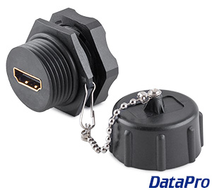
IP68 Waterproof Panel Mount HDMI High Speed Coupler
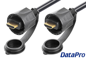
IP68 Waterproof HDMI High Speed Cable Male-Male
limpid nest
heavy jasper
Or: https://www.datapro.net/products/ip68-waterproof-panel-mount-hdmi-high-speed...
Coupler! That's the word I wanted
Thank you!
would it be best to find an IP rated USB-A -> USB-A coupler and then use a USB-A -> USB-A cable to connect my pi to the coupler?
I found a "water resistant" USB-A panel mount device with a USB A cable on the non panel end, but it didn't have a real IP rating
worldly schooner
That's up to your discretion. If you have the budget for it, I'd recommend it, but not all applications necessarily have strict IP requirements.
That being said, Switchcraft has the USB couplers in a form similar to those HDMI couplers as well, just go up one level from the HDMI connectors page.
limpid nest
I was hoping to order as much from digikey as possible, I found the hdmi coupler with the chained on cap on digikey. Let me see if I can find the USB couplers you're talking about
limpid nest
Looking at the wiring diagram for a part I'm strongly considering and there are 2 LEDs depicted, are they built in to the part for optoisolating and if so, why two LEDs?
Datasheet: http://www.crydom.com/en/products/catalog/ed-series-ac-plug-in.pdf
digikey: https://www.digikey.com/en/products/detail/sensata-crydom/ED24D3R/2665174

Order today, ships today. ED24D3R – Solid State SPST-NO (1 Form A) Module from Sensata-Crydom. Pricing and Availability on millions of electronic components from Digi-Key Electronics.
supple pollen
I suspect one is the status indicator so you can see when it's actuated, and the other drives the optoisolator
limpid nest
OK, that's what I assumed, but I reached out to them just in case
I didn't see an obvious LED on the part image in Digikey
supple pollen
It does state "LED input status indicator" and shows a little bump on the top that could be an LED
limpid nest
Ahhh missed that
limpid nest
can I create a unidirectional level shifter on a breadboard with either a IRF640N, IRF740, or IRF51 mosfet(s)?
3.3V -> 5V
supple pollen
Yes, but those are massive overkill
limpid nest
they're what I have on hand haha
supple pollen
Actually the threshold voltage may be high enough to make it difficult
limpid nest
shoot
I'm trying to figure out whether the TPIC6B595 works with the 74HC595 CP lib
so I need to order some other thru hole parts?
or even a thru hole level shifter if that exists
supple pollen
It's worth hooking it up and seeing if it just works with 3.3V logic input. Worst case is it doesn't.
limpid nest
let me pull the datasheets
supple pollen
Here's one option for a through hole shifter https://www.adafruit.com/product/735

Most of our customers love using the Arduino for prototyping, design, and invention but find themselves stuck when trying to connect the Arduino to the latest sensors, displays, controllers, ...
limpid nest
is that software-less?
supple pollen
Yeah, it's just a shifter. This one might be a better choice https://www.adafruit.com/product/1787

Level shifting chips let you connect 3V and 5V devices together safely. This chip is similar to others in the shop (such as the 74LVC125) except this one is particularly good at converting ...
limpid nest
what parameter should I be looking for to see if the ones I have on hand will work
or plot
Looks like the 640N won't work, 3.3V is off the scale for Gate-Source voltage
supple pollen
In particular, look for the RdsON versus gate voltage graph. If you can find one that gets to even somewhat conductive (a couple of hundred ohms would likely be fine) at 3.3V, it could be a candidate. Note that most single-transistor shifters are inverting shifters.
limpid nest
huh, this datasheet doesn't seem to have that https://www.infineon.com/dgdl/irf640npbf.pdf?fileId=5546d462533600a4015355e7be9019ee
AH they do have a VG_S vs I_D plot
But that one doesn't show 3.3V as working'
supple pollen
Most of those power MOSFETs are intended for 12V or so gate signals
limpid nest
Yeah, unfortunately my radioshack has spotty stock on things like this
supple pollen
Again, you could try it, but I'd try just running the shift register from the Pi directly and see if you get away with it.
Heh, you've seen my Radio Shack, it's not really fair.
limpid nest
I'm about to do a big digikey order, I can slip a few of the 74AHCT125s in
supple pollen
Heh, I just ordered a bunch of stuff there. 
limpid nest
I assume 14-DIP is breadboardable?
supple pollen
Yes, they fit usual breadboards nicely
Or if you want more shifters in a single chip, 74AHCT541 or 74AHCT244
distant raven
For what it’s worth, a shift register will bring up IO signals to 5V
I used a 74HC595 with a QT PY. Powered the register off 5V, data lines were 3.3V
Worked just fine
limpid nest
interesting, worth trying first.
distant raven
Oak Development Technologies
In our last tutorial, we walked you through how to expand the output pins of the Adafruit Qt Py by using a 74HC595 Shift Register. In this tutorial, we'll help you take it a step further by adding a momentary button and a few extra lines of code to implem
For some reason my ssl cert dropped 😮
limpid nest
I'm using the 74HC595 with no problems, just trying to figure out whether the hi power shift register adafruit sells will work with the lib. There doesn't seem to be a guide for that chip
Looking at the second paragrph here it seems I want to tie NOT_G to ground and NOT_SRCLR needs to be high? https://cdn-shop.adafruit.com/datasheets/tpic6b595.pdf
limpid nest
so I want to leave it always hi?
distant raven
Unless you want to attach a button to it and manually reset it
distant raven
Yeah
 velvet patio
By any chance are there eagle libraries out there for the reverse-mount sk6812 LEDs that Adafruit uses in recent products or were those created in-house?
distant raven
velvet patio
By any chance are there eagle libraries out there for the reverse-mount sk6812 L...
Check Adafruit eagle library?
You should also be able to extract parts from Adafruit schematic/board files
velvet patio
Haven't but I will
The reverse mount part would be something that would have so many additional ways for me to screw it up creating the part from scratch.
supple pollen
I know that feel
tough matrix
extracting part from eagle files is pretty easy
limpid nest
I can't post great pictures since power is out (using discord on my phone), but I decided to make all my 5V lines .01" thick, do I need to make my RETURN_N lines .01" as well? One sec, getting pic of schematic
supple pollen
I generally make my zero volt lines thick too.
limpid nest
It's taking a while to upload this picture heh
Not working on my poor reception unfortunately
But since they are going into my open collector IC, are they truly 0V
?
supple pollen
Ah, these are your current loop returns. Thicker is nice, but not necessary. You're only pulling a dozen mA or so through them.
limpid nest
Ok cool, my current layout doesn't allow thick traces for those. Should I revert the ones I've already changed?
 median wind
im disappointed at myself 😔 . we were tasked with (among other things) make truth table for nand, and, nor, or, xor inve gates by using leds. But I don't know if there's something fundamentally wrong with this design or if this version of circuitmaker simple doesn't show when the leds are supposed to be on

those logical switches go from 0 to 5 v
distant raven
median wind
im disappointed at myself 😔 . we were tasked with (among other things) make tru...
I would add a resistor in series with the LEDs
LEDs need resistors to limit current in a majority of cases
median wind
it dropped voltage from 4v to ~1.6v but functionally I see no changes to the leds
 supple pollen
limpid nest
Ok cool, my current layout doesn't allow thick traces for those. Should I revert...
supple pollen
limpid nest
Ok cool, my current layout doesn't allow thick traces for those. Should I revert...
Thick traces are normally fine, if there's room, it's more of an æsthetic choice, unless you're considering thermal mass, soldering area, impedance, use of etching chemicals, etc.
median wind
ugh still haven't figured this out, I can see that those that are supposed to be high have ~1.6v those in low have 200mv but i cant get the led tor eflect this
circuitmaker has an analog/digital switch, but if I switch to digital the only difference is that the probe instead of giving me values givess me the option to change from high to low at the different connections instead
distant raven
median wind
circuitmaker has an analog/digital switch, but if I switch to digital the only d...
LEDs and logic gates are run on DC current. In theory you only need high or low signals to change the output of a logic gate. This could be high=5V and low=0V. At 5V, you should expect between 2.5-3V to drop across the LED and 2-2.5V to drop across the resistor on average.
I don’t necessarily thing logic gates would operate on AC voltage sources because AC is generally a sine wave.
supple pollen
1.6V is reasonable, that's likely the forward voltage of the LEDs
limpid nest
I plugged this in and my true wireless headphones started fritzing out. Bad sign?

"What is this" you ask? Very good question
median wind
ok so if I use this kind of led, it actually lits up

though this one seems to only have a connector
it works in digital mode, in analog mode it complains there's no ground, if I connect the ground to it it'll make it turn off (which makes sense as it drops the voltage to 0)
ok, I have no idea what changed, but the previous diode led is working now

but only in digital mode, in analog it doesn't lit up 🤔
median wind
well, in the end I just worked it as digital
using only a 7400 (quadruple 2-in NAND gates) make a circuit that: inverts, is an AND, OR, NOR and XOR (everyone but the invert being 2-in)
ok, inverter down
I think If I nand the output of two inverters I'd get an or, but then I'd already be using 3 out of my 4 gates 🤔
well, im already cheating by having 5 gates and I', still missing the xor and nor
I wracking my brain and I can't come up with a way to give all these 5 outputs with just 4 nand gates
distant raven
Well, think of the output of a nand gate relative to the inputs
If I gave three nand gates, there are a number of configurations you can make
median wind
well, I cheated and looked how to make a xor with nands, and that alone requires the four gates, so I'll instead try and see if I can fit the other ones inside the xor
median wind
I don't think they all can be done with 4 nand gates
distant raven
Well, they might be
heavy jasper
To confirm the way the question is worded: Do they want you to make one circuit that generates all of those outputs at the same time if you tap them off?
Or do they want you to individually make 4 different circuits that each use up to 4 gates?
median wind
well, thats the thing, I didn't know! but I don't think they can be made with just 4 gates, so I did them separately
now I need to make an F = AB + CD with just a CI 7400 (quadruple 2-in nand) but the solution I'm coming up with is using 5 nand :<
hmm wait, maybe I can do this
supple pollen
Wait until you read about gate expanders
median wind
hmm, I think I can do this with 3 nand gates
yeah, I think in this case 3 nand gates acts the same as the 2 and gates and the or gate you'd normally use
 supple pollen
Good use of DeMorgan's theorem
A NAND gate like in a 7400 contains 4 transistors, so a 7400 chip contains 16 total transistors. That got me to thinking, which TTL chip has the fewest transistors?
 rigid kraken
I need to control 5 sets of 3 seven segment leds. Im currently using the AS1115 chip but im looking to see if anybody has any suggestions as to an alternative.
supple pollen
I'm fond of the HT16K33 for jobs like that
Here's one running three 16-segment digits, ten 7-segment digits, a few LEDs, and a keypad.
 rigid kraken
how did i miss this? I looked on adafruit
limpid nest
It's not labeled as such
Well it is but you have to do a bit of reading
All the 7 and 14 segment displays use them, I think you can get a breakout too
The adafruit boards for this (and other products) are a GREAT reference for doing your own design
limpid nest
I'm reviewing a project someone else did, and am trying to grok what they are doing with these decoders and OR gates.

it seems like there might have been a better option here but I'm not sure
 sick geyser
Seems to turn pin 7 into an All On
limpid nest
Pin 7 on the decoder?
sick geyser
Yeah
supple pollen
Looks like it's using the decoder allow 3 I/O signals to turn on one of 8 outputs at a time, and then using the gates to have one of those to turn on multiple outputs at once.
limpid nest
Gates?
I followed the first bit, it's what I was thinking, but I'm not sure what the gates are. I'm just so confused why they didn't use a shift register and some mosfets, but what do I know
Oh OR gates
duh, it's late
Would it help if I uploaded the code?
shouldn't 4 inputs make 16 outputs, not 8?
 worldly schooner
limpid nest
shouldn't 4 inputs make 16 outputs, not 8?
worldly schooner
limpid nest
shouldn't 4 inputs make 16 outputs, not 8?
One of the pins is the decoder enable pin, which gives the code the 9th state of no lights.
supple pollen
A shift register would be a perfectly valid approach, and allow any combination of on and off outputs. It would be a little slower, but since this appears to be doing AC switching, I doubt there's a need for high speed anyway.
limpid nest
worldly schooner
One of the pins is the decoder enable pin, which gives the code the 9th state of...
Ahh ok, but the way the code is written really doesn't seem to match this diagram
limpid nest
supple pollen
A shift register would be a perfectly valid approach, and allow any combination ...
Cool thx
rigid kraken
supple pollen
I'm fond of the HT16K33 for jobs like that
I looked at these but they dont sell them as is, they only sell them attached to breakouts or as parts of modules
distant wraith
has anyone created FSR sensors before? https://learn.adafruit.com/force-sensitive-resistor-fsr/overview
 supple pollen
rigid kraken
I looked at these but they dont sell them as is, they only sell them attached to...
supple pollen
rigid kraken
I looked at these but they dont sell them as is, they only sell them attached to...
If I need the bare chips, I buy them directly from the manufacturer: https://holtekusa.com/orderonline.php
limpid nest
rigid kraken
I looked at these but they dont sell them as is, they only sell them attached to...
You can get them from the manufacturer for pretty cheap
Oops
Lol
worldly schooner
If you can wait the lead times, anyways.
limpid nest
Could always buy a few backpacks and a hotplate and try to remove them
rigid kraken
Thats what ill do for the prototype but if the module im making ges into prodection like i want, then im gonna need to order like 100
limpid nest
eeeep, did I put my header on backwards?


I want this to stack on top of a pi 3 A+
crud, I think I did...
If I just move the header over to the right hand side, would it work out? I am probably going to have to do a complete respin
supple pollen
Just mount it upside down
limpid nest
the silkscreen markings are pretty critical
 gilded plover
I'm looking at getting this 5V PowerBoost. It says it is 500mA at 1.8V but 1000mA at 3.7V. Does anyone know if I can get up to 1000mA off the soldered on USB port? The description makes it sound like the max I can get is 500mA. https://www.adafruit.com/product/1903

PowerBoost is the perfect power supply for your portable project! This little DC/DC boost converter module can run from 1.8V batteries or higher, and convert that voltage to 5.2V DC for ...
limpid nest
How does one figure out what this value is?
 unreal flax
gilded plover
I'm looking at getting this 5V PowerBoost. It says it is 500mA at 1.8V but 1000m...
unreal flax
gilded plover
I'm looking at getting this 5V PowerBoost. It says it is 500mA at 1.8V but 1000m...
I'll depend on what you plug into it. If it's a compliant USB device, it'll probably pay attention to the resistor values and choose to not draw any more than 500mA. But if it's more of a homebrew thing, the boost can supply more.
limpid nest
oops foudn it
gilded plover
unreal flax
I'll depend on what you plug into it. If it's a compliant USB device, it'll prob...
I want to power a Raspberry Pi Zero W and this screen https://www.adafruit.com/product/2406

Its a mini panel-mountable HDMI monitor! So small and simple, you can use this display with any computer that has HDMI output, and the shape makes it easy to attach to a case or rail. This ...
limpid nest
Are there really specific limits to PCB radii in Fusion360? I'm trying to use a radius that matches my corner vias well and it isn't allowing me to
unreal flax
limpid nest
Are there really specific limits to PCB radii in Fusion360? I'm trying to use a ...
There shouldn't be. Often the PCB outline is a rectangle with infinitely sharp corners.
limpid nest
Huh, I'm in mm because I'm punishing myself and it won't let me do 1.833 mm
supple pollen
That's odd, it should be fine.
limpid nest
Yeah, I think software is afraid of me, I've written some really bad examples of software
limpid nest
Have I peered into the depths of lovecraftian madness? Or am I just trying to find the anchor point of this silkscreen text?
 tough matrix
first applications of my new scope - testing the I2C bus.
What bothers me are these negative spikes on SCL line - are they usual? or is something wrong with my design?
 limpid nest
It's only the SCL line?
tough matrix
SDA line also has some spikes, but not as significant
limpid nest
I plan to bother you in a few months to see if you like this scope BTW
supple pollen
Probably a probe grounding issue
tough matrix
supple pollen
Probably a probe grounding issue
Oh! possibly
I connected the ground of the probe to ground of the board, of course - is there something I need to worry about whne doing it?
tough matrix
limpid nest
I plan to bother you in a few months to see if you like this scope BTW
sure, would be glad to give my review
supple pollen
Was it a very short ground lead directly to a ground plane? Or several centimeters of clip lead?
tough matrix
about 10cm
limpid nest
I was hoping that discord would have a "hart" sticker, but I have to rely on a visual pun unfortunately
supple pollen
10cm can easily make it look like there are spikes present when there aren't really. https://www.analog.com/en/technical-articles/short-ground-leads-make-better-scope-photos.html
I often ask customers to send me oscilloscope photos showing the ADC interface timing of their circuits. Occasionally, what I get back is a waveform with large amplitude ringing or even something that resembles a sine wave for what should be a relatively clean square wave. When asked how the scope probe was grounded, they will say that the standard
tough matrix
thanks
will go and read
distant raven
supple pollen
10cm can easily make it look like there are spikes present when there aren't rea...
This is good to know
I want to design a probe test board with Coaxial ports for connecting a scope or VNA to
supple pollen
Not that my scope probe arrangements are always the best
 distant raven
I know those connectors though can be pricy. Plus my VNA could only really probe a 4G LTE antenna or anything 1.5GHz or less
limpid nest
I'm seriously confused, I set up some screw terminals like so:

But on my board, one of them is like so (haven't checked the other)

(will need to open the full pic to see completely)
slightly clearer

The other one is fine
So it's just the lower one in the schematic
unreal flax
You haven't quite said what is wrong.
limpid nest
ah
the signals don't seem to match the schematic
There are no +5V signals on one of them

Here's what the signals turned out as on my board
Super wrong
ahhhh something is up in my schematic

thank you all for being my ducky
tough matrix
tested with short ground leads (wire wrapped around probe barrel). Spikes still there, but much less pronounced, so I do expect it to be an artefact of lead inductance....
heavy jasper
Have you done scope probe calibration as well? It could be that the very fast falling edge is causing your probe itself to ring.
There should be a probe calibration square wave output, you can hook up to that and see if you still see the ringing. If so, you can adjust the trim on the probe base.
(Since you said it’s a new scope, and that could also explain why it’s worth on scl than sda, especially if you’ve only used one probe for each)
 worldly schooner
limpid nest
worldly schooner
limpid nest
Impedance matching. For high-speed differential signaling, it's important that the traces have the same resistance to ensure the signals match each other without any asymmetrical distortions.
limpid nest
ahhh thought it was somethig like that
worldly schooner
Since traces have a finite resistance, PCB designers will intentionally increase the length of certain traces to get the impedances to match a certain value.
unreal flax
It's length-matching rather than impedance-matching in this case, to keep high-speed signals in sync.
Controlled-impedance traces would have a specific width rather than length.
limpid nest
does "in sync" mean that a+ signal should take exactly as long to travel down as a - signal?
unreal flax
limpid nest
does "in sync" mean that a`+` signal should take exactly as long to travel down ...
Yes, and a clock signal should get there at the same time as a data signal, or bit 0 of a bus should get there the same time as bit 31, etc.
limpid nest
makes sense thanks!
I'm only using a few milliamps per 5V trace on my board (16 mA worst case per trace), can I get by with 6mil traces?
worldly schooner
unreal flax
It's length-matching rather than impedance-matching in this case, to keep high-s...
Durrr, you're correct. Thank you for correcting me.
unreal flax
limpid nest
I'm only using a few milliamps per 5V trace on my board (16 mA worst case per tr...
Yes, that should be perfectly fine.
limpid nest
Thanks!
Is there a way to upload a fusion 360 board design? I'm having a hard time finding the actual folder my project is stored in
tough matrix
all fusion designs are available on autodesks's cloud storage, a360
limpid nest
Ahh
tough matrix
you just need to make the link publicly accessible
limpid nest
OK! I think I can do that
Any idea if this guide really fits for JLCPCB? https://www.arxterra.com/jlcpcb-drc-generating-gerber-files-and-ordering/#Running_a_DRC_with_JLCPCB_Settings
tough matrix
for sharing fusion 360 designs: open design in Fusion 360, then in File menu, choose "share->public link"
limpid nest
ooh, does it expose my email?
tough matrix
let me check
here is one of my shared designs: https://a360.co/2RdlnCH
Share 2D and 3D design files and project files with anyone.
tough matrix
I usually use default DRU rules; they are more conservative than JLCPCB, and I rarely need to push it.
Just in case, here are JLCPCB capabilities (but not in the form of DRU file): https://jlcpcb.com/capabilities/Capabilities
worldly schooner
limpid nest
If you use JLCPCB,how do you go about getting their DRU?
Do you mean, "if you don't use JLCPCB"? The guide you linked provides the DRU for you, it seems.
limpid nest
It provides something someone else made, I don't know that it's correct
worldly schooner
Otherwise, it's usually a process of finding out their capabilities and manually entering them.
tough matrix
I haven't checked that particular DRU file, but you can inspect it and check if it matches what is on the JLCPCB site. And your design seem easy enough - you do not need anything complicated such as blind vias or traces less than 6mil or anything like that, so DRC check would mostly be to verify that you have no airwires or wrongly connected signals.
limpid nest
OK cool, I don't love the idea of downloading random code from someone else, although I think a DRU is more like a bunch of raw data to be read by F360/Eagle
Should I change these at the least? Mine are all 6 mil by default
 limpid nest
Are + and - based names (e.g. Day 1 + and Day 1 -) bad names for the positive and return paths to my relays since they aren't differential signals?
On the silkscreen
tough matrix
I'd say they are ok; one issue is that - can be easily lost (visually) on silkscreen, whereas GND is much more visible
limpid nest
tough matrix
I'd say they are ok; one issue is that - can be easily lost (visually) on silksc...
Ah, the only issue is it isn't true ground, it's the return to a common collector transistor array I'm using to sink current
I was hoping to PM someone my design for a quick review, if anyone is willing, please ping me
tough matrix
@limpid nest I am not a great expert, but would be happy to take a look
limpid nest
Thanks, let me get the shareable link. Another pair of eyes is very valuable to me
should I share the whole "electronics project"?
heavy jasper
I'll take a look as well if you're willing to post the link here and get review on the channel
(so other folks can learn as well)
limpid nest
My only concern about posting the link is I can't figure out if it exposes my email
heavy jasper
If you can just download a copy of the design files themselves
and upload them here
that works too
heavy jasper
when you have the project open, is there some "export" or "save local" or other options in the menus?
limpid nest
I can export to "autodesk Fusion 360 Archive files"
taking a look at what's in the shareable link, it doesn't seem that easy to review.
it doesn't have my power/gnd pours for instance
distant wraith
hey guys,
i have just gotten a gerber file for a pcb i have had in work with a freelancer. Im just wondering as there are some components on the pcb is there an additional file i should have which lists what part belong on waht section? And also would i be able to see all the traces on the gerber files, as he ensured me that they were all connected but when looking at it i am not able to see a single trace in gerbview
 limpid nest
Let me make some gerbers of my design and see if I can see them
keep in mind I'm using F360 gerber viewer so YMMV
heavy jasper
gerbers + schematic as a PDF would be OK
limpid nest
I suspect it's a layer issue
distant wraith
i have only been given the gerber files, so am i missing some files?
heavy jasper
BOM won't affect whether the traces are connected or not (which is the core question)
limpid nest
In F360 gerber creator/viewer I can indeed see traces
heavy jasper
Oh, I'm answering for Naraka atm
limpid nest
I was too haha
heavy jasper
Yeah, the gerbers are just "here's a plot of all things on this layer" with no more subtlety than that
At the very least this seems to only have one layer of copper visible
If you're willing to dump the gerbers you got here I can take a look.
(and if they sent you the raw design files, I may have the tool to open them as well)
distant wraith
those are the different layers i have
 distant wraith
heavy jasper
If you're willing to dump the gerbers you got here I can take a look.
distant wraith
heavy jasper
If you're willing to dump the gerbers you got here I can take a look.
do you mind if i PM you due to them being for a big project im working on currently?
heavy jasper
Do you have sole authority/signature authority to disclose them?
distant wraith
heavy jasper
Do you have sole authority/signature authority to disclose them?
yes as i am the authorised person for this project
heavy jasper
Okay, checking because I have no desire to be on the other end of an NDA dispute
Sure, you can PM them. If there's a technical answer I'll respond here in general terms w/o any additional screenshots
Edit: sure seems like the traces weren't actually routed. Folks will be followed up with.
heavy jasper
I did one time have a friend early in his college EE career be under the false impression that the ratsnests were routed traces
limpid nest
ooops!
heavy jasper
and shipped the board to the manufacturer without any actual routes.
limpid nest
I hope the MFG noticed!
heavy jasper
the manufacturer came back and said "excuse me sir, we normally don't question what folks send us too much but.... did you mean to have some traces here?"
limpid nest
haha
I got an email asking if I meant to do what I did once (copper on only one side, it was an art project).
distant wraith
sorry to bother again, so i should have a gerber file, Bom file and a PCB file ? are those all the files needed to work on the PCB later on or would there be some extra files i would also need if some changes would needed to be made to the pcb?
heavy jasper
I would request both the manufacturing files and the source project files.
distant wraith
ok great 🙂
heavy jasper
manufacturing files ideally are: gerbers+drill file, BOM, placement file, netlist, and the somewhat superset ODB++ files if the tool supports generating them.
(if you're planning on having them professionally assembled, and not soldering them by hand)
limpid nest
I am sanity checking my design and per @tough matrix's suggestions I am making sure that my footprint for a 2 position terminal block is right. Am I reading this datasheet right (https://media.digikey.com/pdf/Data Sheets/Phoenix Contact PDFs/1725656_Ds.pdf) and it's normal for the 5 position one shown in the drawing to not have posts? Only the 2 and 3 position ones do?

oh sorry, apparently I'm linking too much
Order today, ships today. 1725656 – 2 Position Wire to Board Terminal Block Horizontal with Board 0.100" (2.54mm) Through Hole from Phoenix Contact. Pricing and Availability on millions of electronic components from Digi-Key Electronics.
tough matrix
3d models provided by Phoenix seem to confirm that: https://www.digikey.com/en/products/detail/phoenix-contact/1725672/267464
Order today, ships today. 1725672 – 4 Position Wire to Board Terminal Block Horizontal with Board 0.100" (2.54mm) Through Hole from Phoenix Contact. Pricing and Availability on millions of electronic components from Digi-Key Electronics.
limpid nest
Yeah I'm as sure as I can be that I got it right. It seems the posts go in front of the conductors on your board
tough matrix
yes
limpid nest
If you're free and willing to check out my changes I made based on your suggestions that would be super excellent
tough matrix
and hole diameter should be 1.1mm

 proper anvil
Im trying to use these switches for a simple project, but I can't find a part number or datasheet on the amazon listing, and by extension I can't find a footprint to use in easyEDA. Is there someone experienced with easyEDA that could teach me how to make a custom footprint for it? Im not sure how to make rectangular holes
 heavy jasper
Without knowing the actual dimensions (either from a data sheet/drawing or you taking a set of calipers and measuring them), it’s pretty much impossible to make a footprint. You would probably either make slot holes for this, or just circles if the two poles are placed far enough apart that the circles don’t collide. That said, in general, this doesn’t really look like it’s meant to be soldered into a PCB, more likely you’re meant to panel mount it, then solder wires in.
proper anvil
I've got them on hand and can accurately measure them by hand, but yeah, they're not made for through-hole. It's for a small production of handmade boards so as long as I can get the holes placed correctly it should work
worst case ill just use round holes and they'll fill with solder
proper anvil
I've now created a footprint. But how do I get this into my schematic/pcb design?
limpid nest
Which CAD program?
if EAGLE/F360, did you create a library?
Is this a proper way to create a pulled up signal on my reset pins? I want the same signal to reset both shift registers
 proper anvil
its easyEDA, i ended up just placing the holes manually on the PCB and setting the nets

without making a schematic since it's simple enough
limpid nest
Ah I haven't used EasyEDA enough to know the process, looks like you figured it out though 🙂
distant wraith
when adding a different layer into a PCB what do i have to choose as a setting? Im looking at adding flex substrate semi-conductor as a layer on my flex pcb. I havent been able to find any information on how to add this to a pcb online 😦
unreal flax
distant wraith
when adding a different layer into a PCB what do i have to choose as a setting? ...
This is just going to depend on the EDA tool or the website you're using.
distant wraith
The tool im using is kicad
limpid nest
I forgot to order pullups for my board, can I bodge a thru hole 4.7k or 10k resistor on there until my chip resistors come?
 unreal flax
limpid nest
I forgot to order pullups for my board, can I bodge a thru hole 4.7k or 10k resi...
unreal flax
limpid nest
I forgot to order pullups for my board, can I bodge a thru hole 4.7k or 10k resi...
Yep, the exact value doesn't matter.
And you may be able to get away without it completely, if the chip has a weak internal pullup on that pin.
limpid nest
ok cool thanks!
limpid nest
unreal flax
Yep, the exact value doesn't matter.
you say value doesn't matter, is anything wrong with a 10k?
unreal flax
limpid nest
you say value doesn't matter, is anything *wrong* with a 10k?
I don't know the full extent of your design, but generally the pullup would just need to be strong enough to keep the pin from floating, and not strong enough to overpower the logic-level input. So anything from about 1k to 100k ought to be fine unless there's something unusual involved.
limpid nest
I don't think anything unusual, it's just a SPI connection to some 74HC595s and some common collector current sink arrays
velvet patio
For a non-i2c logic pullup the value is pretty much unimportant.
10k seems to be the general rule of thumb for non-i2c since its so commonly used in everything.
And minimizing the number of unique values used in a project is always good.
 smoky mica
these rotations feel... illegal

but really tho, is it fine if i make the board like this? I don't think ive ever seen a board built like this so its weirding me out
distant raven
Yeah
supple pollen
I rather like the æsthetic
 limpid nest
You've probably owned products with boards like yours
distant raven
Note, the mounting holes are not symmetrical
 long wraith
smoky mica
these rotations feel... *illegal*
long wraith
smoky mica
these rotations feel... *illegal*
This hurts my soul... but if it works it works
supple pollen
The Orange Pi uses odd-angled chips too
 smoky mica
they just
✨ Funky Rotations ✨
 distant raven
supple pollen
The Orange Pi uses odd-angled chips too
distant raven
supple pollen
The Orange Pi uses odd-angled chips too
I feel like they were just trying to give someone an aneurism
supple pollen
There's an ad floating around for a PCBA house featuring a really nicely done triangular PCB with parts artfully and symmetrically arranged.
distant raven
PCB layout definitely is an art
smoky mica
supple pollen
The Orange Pi uses odd-angled chips too
my design was at least almost acceptable but.. like. those are BGA chips?!?!?
cursed asf
distant raven
Looks like BGa
But BGA isn’t bad to design with
Just tricky
My watch design for instance uses a tiny BGA or WLCSP (some weird acronym) version of the nRF52811-CAAA-R7
Picking drill and annular ring sizes that work with a fab’s specs is tricky though
Typically you end up having to do like 6 layer services to get via small enough
smoky mica
i was gonna use a ~3x3mm BGA package for the SAMD21 but decided against it, cause yk its 3 friggin millimeters and i cant do that
supple pollen
Heh, some of the drills in my last board were 3mm
distant raven
Lol
Yeah, the drill on my watch is like 8mil with 4mil annular ring
Which is like.. 0.33mm
Lol
supple pollen
Mine was really not a very demanding board. It was almost one layer.
 distant raven
In the words of snobby PCB designers, there is no single layer PCB. Just two layer boards with no copper on the other side 😆
supple pollen
A flyback transformer. But I have built nixie boards.
 smoky mica
oh nice
supple pollen
Certainly neater than the prototype

 tidal cliff
If I have a part that has through-hole pins that are only 1.2mm long (such as on a USB C connector) do I need to use a pcb that’s 1.2mm thick or does it need to be even thinner than that?
velvet patio
Think I'm gonna have to reduce my 4x5 keyboard to a 4x4 to get it to fit into free eagle size limits.
For some reason I had it in my head the limit was 100x100mm not 80x100
supple pollen
See my nixie boards above? I needed 8 tubes, but Eagle only gave me room for 4, so I split it into two boards (the connector pads on the ends are for headers to daisy chain them).
velvet patio
I don't really fancy having to learn kicad
You really seem to love the high voltage stuff
supple pollen
I figure it's no harder than Eagle, just ... different. And if I don't like something, I can change it (yay open source). But I'm kinda sticking to my $1400 Eagle license for as long as I can.
distant raven
Okay... I need a quick sanity check
there really isn't much difference between SOD-123 and SOD-123F right?
looks like it's just... ever so slightly short for the SOD-123F but should make contact with an SOD-123 footprint
 onyx kernel
Its me again this time with PCB 2.0. I'm planning to order this one but maybe someone finds some mistakes i made.
 supple pollen
You may want a capacitor on the reset line, and "indication" is misspelled.
onyx kernel
what track with do you recomend? ive done 0.254 for the switches and chips and 0.5 for the leds and the battery. is that ok?
distant raven
Designed the fun little wifi neopixel light controller
 worldly schooner
Ooooo that's a cute board. What do you plan to do with the buttons?
distant raven
user input for changing the strip colors or animation
it'll be circuit python programmable so you could program the buttons to do what you want
also arduino too if you prefer arduino
worldly schooner
Hm, would you be able to replace the two buttons with a rotary encoder?
distant raven
possibly could add one if I do a bit of rerouting
worldly schooner
I feel like using two buttons doesn't give you much control, but idk how many GPIO you have...
distant raven
well, you could use the boot button as a user input as well
worldly schooner
With a single rotary encoder + push button, you could make a fairly intuitive set of controls for a simple GUI as well.
Ah, that's true
distant raven
so user 3 buttons
there is also an i2c ambient light sensor too so if you want the lights to turn on when the main lights go out
might be able to use the ambient light sensor as a "button" if you set your program up right
supple pollen
onyx kernel
what track with do you recomend? ive done 0.254 for the switches and chips and 0...
I'll normally use fat tracks for power and ground (or a ground plane) and skinnier tracks for data.
onyx kernel
ok how thin?
distant raven
6-8mil is usually fine for data
which is... some value in mm let me convert lol
0.15-0.20mm
onyx kernel
ah ok i was worried i had to reroute everything 🙂
distant raven
10mil or 0.254mm is also a pretty common size
power should be as big as possible for your board
if you can have a solid ground plane to drop via to, even better
tough matrix
quick questions for people who have experience with rp2040
is there a way to program them without using USB connector?
some kind of jtag/sad connectors maybe?
swd , not sad:)
tough matrix
nice
distant raven
on the PICO, the pins on the end are SWD pins
worldly schooner

A complete tutorial on programming and debugging Raspberry Pi Pico using SWD Interface. Learn how to Program Raspberry Pi Pico with SWD.
tough matrix
thanks a lot!
 queen bay
does anyone like having 3d modeled electronic components for their builds? https://puu.sh/Ik6tt/8e463b38d1.png
 distant raven
I try to model them if I can get all the part models
tough matrix


Checkout out this plugin by @bouni2016 that adds @JLCPCB/@ElectronicsLcsc integration to @kicad_pcb!
It allows querying the JLC parts database and assigning LCSC part numbers, and it generates BOM + CPL + Gerber files for JLCPCB!
 Twitter
·
Twitter
·
if this works as advertised, this will be a huge timesaver
worldly schooner
Oh, time to make the jump to KiCad lol
limpid nest
eep! It's build day, time to see if I made any major errors!
 bright thistle
welp, dare I say it's time to consider my PCBs as lost in the mail? :/
serves me right for using standard mail instead of tracked
limpid nest
How possible is it to turn a regular toaster oven into a reflow oven? I know there are kits but I don't know enough to evaluate them
long wraith
Toaster? hard. Toaster oven? Not so hard
Oh wait you said toaster oven, lol... Yeah, not too hard
long wraith
Can't find the exact guide, but I did something like this https://www.instructables.com/Automatic-SMD-Reflow-Oven-From-a-Cheap-Toaster-Ove/

Instructables
Automatic SMD Reflow Oven From a Cheap Toaster Oven: Hobbyist PCB making has become much more accessible. Circuit boards that contain only through-hole components are easy to solder but the size of the board is ultimately limited by the component's size. As such, utilizing surface mount components ena…
Got a toaster oven from a thrift shop for like $10
limpid nest
Bookmarked!
long wraith
Or was it $5? cheap, lol
distant raven
unexpected maker had the Reflow Master
not sure if it's in stock though

Unexpected Maker
Reflow Master is a toaster oven Reflow Controller with a color interface and graphical display of the reflow process. Now includes a new Bake Mode which you can use to dry your 3d printer filament, bake your RGB LEDs or dry your PCBs after they've been ultrasonically cleaned!
long wraith
Nice
supple pollen
Another option: http://www.whizoo.com/
limpid nest
I think someone mentioned stargirl having a good setup? I don't ping people with pinkred names tho
The whizoo looks promising
I also need to dry large silica "packets"
distant raven
I’m just saying, if you absolutely hate your computer… run auto router on a Large BGA chip lol
distant raven

these trace routes are... abysmal xD
oh oh a few got up to 100% routed which is new!
limpid nest
I once spent a while fighting with the auto router before I realized that the settings were only telling it to trace on one layer
distant raven
hahaha... good times
i rarely ever use autorouter
but i love watching it try to route BGA signals
this says it's routed my laid out signals 100%

this is a ARM A72 I think with some LPDDR memory
it is specifically... the STM32MP157AADT3T
lol
limpid nest
Have fun haha glad that isn't my job to route
limpid nest
You are forgiven
distant raven

yet another feather lol
this time an ESP32-C3 mini module
pin usage on the feather will be weird as the mini module just doesn't have enough IO for everything
distant raven
shouldn't be too hard to route...
 tough matrix
what is it?
distant raven
ESP32-s2 version of the esp-01 module
long wraith
distant raven
I’m just saying, if you absolutely hate your computer… run auto router on a Larg...
I bet my spaceship workstation can do it in a flash
limpid nest
You'll need to find an EDA/CAD program. kiCAD is popular and free
limpid nest
I know of fritzing but am not familiar enough to say
supple pollen
Kinda: they ask for money, but there are ways around it
supple pollen
One is to download the source code and compile it yourself
 rigid plume
or if kicad is better
supple pollen
In my opinion, it's worthwhile to learn KiCAD
limpid nest
KiCAD also has a new JLCPCB/LCSC plugin
Could make ordering parts easier if it works as well as advertised
rigid plume
gonna watch some tutorials on kicad then
supple pollen
I'm hoping the plugin supports slots, but if it doesn't, it could be extended (I'll find out if my existing approach worked when the boards show up)
rigid plume
is jlcpcb still good
it's the cheapest and they still have the 5 pcbs for 2$
which is good
supple pollen
I find JLCPCB still good
 rigid plume
oh cool
osh park is really expensive in my opinion but it should be really high quality
distant raven
OshPark is better for small boards
But I’ve found instances where shipping costs from JLC was more than OshPark for some larger designs I’ve done
But JLC has been getting progressively worse lately, especially with a lot of bigger makers like UnexpectedMaker, And others.
rigid plume
In my opinion I think for oshpark you pay for local delivery and high quality U.S made pcbs while with jlcpcb you pay for the cheapness and the many features to change your pcbs.
distant raven
Plenty of people moving to PCBway
rigid plume
Is it like an alternative to JLC
limpid nest
distant raven
But JLC has been getting progressively worse lately, especially with a lot of bi...
Worse how?
distant raven
PCBBuy and PCBHero have been coming up but their marketing practices have been kind of invasive or down right theft of content
distant raven
limpid nest
Worse how?
Constantly changing design files
Or just poor quality
The HASL finish on some boards I’ve received recently has been very poor. Gloppy and inconstant
And ENIG finish + shipping ends up being more than getting from OshPark
Some people manufacture boards through JLC without issue
rigid plume
I melted a part of a pcb from JLC when I tapped my iron on it
distant raven
And maybe a majority of one off boards have been fine
But my results from larger PCB orders have been less than desirable outside of my own mistakes like not realizing I wasn’t including the milling layer in my gerbers 😛
rigid plume
How do I transfer this schematic to kicad it's an png or do I have to manually place the components in my new schematic?
 limpid nest
You'll have to manually place the parts
That's how kiCAD knows what's supposed to be connected on your PCB
rigid plume
whats this?
 limpid nest
I'm not sure
rigid plume
it looks like an spi but i don't think it is
distant raven
Probably a header pin
limpid nest
That was my guess
rigid plume
i think it's the terminal block on the dc-dc booster

also are there any terminal blocks in kicad
rigid plume
supercapacitor charger and dc 3-34 battery
limpid nest
Ahhh ok
But yes I'm 99.99% sure there are terminal blocks in kiCAD
Don't know where to look though
rigid plume
I can't seem to find it
 steep fog
smoky mica
these rotations feel... *illegal*
steep fog
smoky mica
these rotations feel... *illegal*
it looks like you have multiple IMUs on that board, so it might make things harder software-wise if they are at weird angles to each other
tough matrix
rigid plume
I can't seem to find it
 rigid plume
cool ok
rigid plume
tough matrix
I need a dc - dc 3.4 - 34 v boost and I can't seem to find one except on aliexpress
tough matrix
note that in KiCad symbol (which is what you place i schematics) and foot print are separate, so after placing symbol in schematics, you will be asked to choose a footprint
from 3.4 to 34 is a lot... you do need 34v output??
rigid plume
that's what the project page says
but I think lower would be fine
3.4 to 25 or 20v or something
limpid nest
I'm wary of stuff over 30 volts, just be careful
rigid plume
it should be kinda safe as it's dc
limpid nest
Could still get hurt with DC
rigid plume
I know but I wouldn't just be shoving this inside my mouth lol, i'll be fine
limpid nest
Oh good heh
rigid plume
what happens if you do that with 240ac lol
limpid nest
Very bad things
rigid plume
yes
rigid plume
tough matrix
note that in KiCad symbol (which is what you place i schematics) and foot print ...
is this good?
limpid nest
I'm getting a "this page does not exist " error
tough matrix
same here
tough matrix
still "page doesn't exist"
BTW, can you provide a link to the original project you are recreating?
rigid plume
wait
In the project he's using a perf I wanna try to put it on a pcb

Instructables
The Forever Rechargeable VARIABLE Super Capacitor Battery !!!: Hi there!
Welcome to my ENVIRONMENTALLY SAFE, FOREVER RECHARGEABLE SUPER CAPACITOR BATTERY PACK INSTRUCTABLE!!!
What's all the Hubbub, bub?
This circuit acts as a never-dying, forever rechargeable battery. If treated properly and with r…
distant raven
Lol just barely beat ya
rigid plume
a
tough matrix
I'd suggest this: https://www.pololu.com/product/799

This powerful, adjustable boost regulator can generate an output voltage as high as 25 V from an input voltage as low as 1.5 V, all in a compact, 0.42″ x 0.88″ x 0.23″ package. A trimmer potentiometer lets you set the boost regulator’s output voltage to a value between 4 and 25 V.
it goes only to 25v, but Pololu is certainly way more reliable vendor than random guy on AliExpress
if you need other voltages/current capabilities, Pololu has a bunch of them: https://www.pololu.com/category/132/step-up-voltage-regulators
tough matrix
oh
check pimoroni

This powerful, adjustable boost regulator can generate an output voltage as high as 25 V from an input voltage as low as 1.5 V, all in a compact, 0.42″ x 0.88″ x 0.23″ package. A trimmer potentiometer lets you set the boost regulator’s output voltage to a value between 4 and 25 V.
rigid plume
I was thinking of ordering everything of mouser as they have everything I need
supple pollen
If you're in the UK, you can also look at Rapid and Farnell
rigid plume
yep
tough matrix
not sure if mouser has something like this - they might. But pimoroni is local to UK, so shipping shouldn't be an issue
rigid plume
Now how do I add this to kicad
tough matrix
you just add a 3-pin 0.1" pin header
(and leave enough room on your board for the actual booster board)
which you will solder to that male header
limpid nest
You could also make a simple footprint that has the pin headers and a silkscreen outline of the board
tough matrix
whose great idea it was that the two kinds of 3.5mm Neopixels, ws2812B-mini and sk6812-mini, have identical footprint but different pin assignment?
rigid plume
this pcb is a bit to complicated to me I've just been thinking about where to put stuff and the layout.
And what's the difference between 5farad caps and the projects 400 farad caps will the circuit still work ?
supple pollen
Creating your own footprints can be fun

The different capacitors work the same way, but naturally the large ones store more energy. If they're different sizes, you can come up with a footprint that accommodates both of them.
smoky mica
steep fog
it looks like you have multiple IMUs on that board, so it might make things hard...
omfg i forgot about that
rigid plume
is there anyone I can pay to just design a pcb lol
distant raven
supple pollen
Flyback transformer
If it was used for time travel it would be a Marty McFlyback transformer
unreal flax
rigid plume
is there anyone I can pay to just design a pcb lol
If you're serious about that, there is an Adafruit jobs board where you can likely find someone.
rigid plume
unreal flax
If you're serious about that, there is an Adafruit jobs board where you can like...
Where's that
unreal flax
rigid plume
Where's that
It's easily searchable, but it's at https://jobs.adafruit.com/
Find maker jobs in 3D and CAD, Art, Design, Education, Embedded Development, Engineering, Fabrication, Marketing and Communications, and Web Development
supple pollen
distant raven
If it was used for time travel it would be a Marty McFlyback transformer
Might go well with this thing I knocked together a while back

I'm still working on the time circuits
 distant raven
Hehe
supple pollen
rigid plume
is there anyone I can pay to just design a pcb lol
While I could probably knock out a simple board like that in an hour, I would have a hard time keeping myself from re-engineering it.
proper anvil
Hello, might be wrong channel, but im looking for a sanity check in interpreting this datasheet for a DP3T slide switch. My understanding is that
1.) each side (top/bottom in diagram) is independent (i.e. common on top is not connected to common on bottom)
2.) common is connected across each side
3.) the box represents the position of the switch
4.) looking at the top side only, common is connected to 3 when switch is in center, common is connected to 2 when in left position, common is connected to 4 when in right position?

ultimately the goal is to have an input, and two motor outputs- in the center position, both motors are off (totally disconnected), in the left position the motors turn one way, in the right position the motors turn the opposite way. Does this look like it accomplishes that? I'm a meche intern that finds myself doing PCB design somehow lol. Pins 11 and 12 are just anchor pads.

 supple pollen
I am accustomed to DP3T slide switches having 8 pins, so I'm unfamiliar with this arrangement.
proper anvil
thing is, we've already got a ton of these on hand that i've made perfboard prototypes with, but we need 100 within a few weeks so need to get it right on the first try... i've already designed a pcb we can order and solder these into but it'd be more convenient to get them assembled but lcsc doesn't have any such switch. besides, they're panel mount so they're kind of awkward to have soldered to a pcb.
 supple pollen
Your best bet is to look at the data sheet (here's one I picked at random from LCSC's offerings)

And yes, LCSC has a nice selection of them.
proper anvil
Which side of the footprint indicates the opening of the terminal? I need to make sure that when it is assembled it doesn't come in backwards, that would be bad...

im assuming the left side is the opening, but im not sure.
proper anvil
supple pollen
Your best bet is to look at the data sheet (here's one I picked at random from L...
I ended up just using this switch instead specifically because it has the switch function table. Need to make sure I get it right the first time...
chatted with a support rep who asked an engineer, the rectangles correspond to the opening like I thought. so thats good
rigid plume
Hey im wonderingg how you can connect a potentionmeter
https://gyazo.com/5156f87e35b1bcf3c9cdff1962e411f1 o nthis circuit it's like this

how do i add that to this
it has 3 outputs
 rigid plume
tough matrix
you just add a 3-pin 0.1" pin header
rigid plume
tough matrix
you just add a 3-pin 0.1" pin header
how do I find that in kicad
tough matrix
the symbol is in "generic connectors" library
rigid plume
tough matrix
the symbol is in "generic connectors" library
this?

also what's this https://gyazo.com/2b153b789191a82b77d4ad89144f2878
 supple pollen
As you can see, the wiper and one end are connected together, so you do the same and connect one end (say, terminal 3) to the other resistor, and connect the other end (which would be terminal 1) and the wiper (terminal 2) together and to wherever it goes in the rest of the circuitry.
worldly schooner
rigid plume
https://gyazo.com/75dd7a391c6ed98cfa38f05c085a31de
Wire from R_POT:1 to CP1:1 and R, and wire from R_POT:2 to R_POT:3 and whatever else is off to the left of that screengrab.
rigid plume
Oh ok
supple pollen
Swap 1 and 3 if you want the pot to increase "the other way"
 worldly schooner
rigid plume
https://gyazo.com/599e08c84caaff95818b5360189e24b8
worldly schooner
rigid plume
https://gyazo.com/599e08c84caaff95818b5360189e24b8
Pretty much, though for clarity I'd move the wire form R to R_POT up a little.
 worldly schooner
Not sure what this is, but the jumper seems to be there to easily switch between a 1Ohm and a 2Ohm setting.
 worldly schooner
rigid plume
is a jumper just a wire
worldly schooner
rigid plume
is a jumper just a wire
In the context of general schematics, a jumper indicates a connection that can be removed and replaced freely, though usually only when the system is off.
In the context of PCBs, a jumper is usually a little plastic piece that gets plugged onto a pair of male header pins to electrically connect two buses. https://www.digikey.com/en/products/detail/sullins-connector-solutions/STC02SYAN/76372
Order today, ships today. STC02SYAN – 2 (1 x 2) Position Shunt Connector Black Closed Top 0.100" (2.54mm) Tin from Sullins Connector Solutions. Pricing and Availability on millions of electronic components from Digi-Key Electronics.
worldly schooner
rigid plume
and whats https://gyazo.com/aa4a50d2b2dd7289ea4b11d5ed2c2d13?token=4df3c02387f70...
Looks like a reference voltage for the boost converter going somewhere else. Can't say where it's going without more context.
rigid plume
https://www.instructables.com/The-Forever-Rechargeable-VARIABLE-Super-Capacitor-/ here's the project page
here's what i have so far

this part is what is confusing me

im going to be using this https://shop.pimoroni.com/products/pololu-adjustable-boost-regulator-4-25v dc-dc boost
and this voltmeter

aliexpress.com
Smarter Shopping, Better Living! Aliexpress.com
how does the output of the capacitors connect to the dc-dc board and the volt display
worldly schooner
That 2x3 rectangle is a DPST switch
rigid plume
worldly schooner
That 2x3 rectangle is a DPST switch
I can't find it in kicad
can only find these
 worldly schooner
Oh, wait, try DPDT
 tough matrix
rigid plume
https://gyazo.com/8f9541656ac0d6b3f40c9d0dfd8ac3dd
tough matrix
rigid plume
https://gyazo.com/8f9541656ac0d6b3f40c9d0dfd8ac3dd
yes
and when creating the pcb, use footprint from library "connectors pin header 2.54mm"
rigid plume
how do i connect it up
tough matrix
if i remember correctly, it was to connect the boost converter
look at pololu boost converter, it has 3 position header: vin, vout, gnd
just need to find out in which order they go
 rigid plume
would it be ok if I send you the file for you to do for me
tough matrix
not now, sorry. Too busy with other things
rigid plume
oh ok

the 2nd pin on the boost converter is ground
the 3rd is live
and 1st is vin
worldly schooner
rigid plume
https://gyazo.com/3edd69202e178aea75feab66e83bb10c
Switch 3 and 4. 5 is display reference, goes to your voltmeter. 6 is your boost ref, pulled from that wire between boost:3 and terminal:1.
Pin 2 of the boost converter should just be grounded, doesn't need to connect to the switch.
When the switch is off, the voltmeter should measure the voltage of your capacitors. When it's on, the capacitors will connect to the boost converter, and the voltmeter will switch to the voltage of your boost converter.
Basically, the left side of your switch is the power connection, and the right side switches the displayed measurement.
worldly schooner
Can, or can't?
worldly schooner
If you're looking at the original schematic provided, the numbers should go 1 to 6 from left to right, top row then bottom row.
 worldly schooner
No, 5 goes to the voltmeter...
Switch 3 and 4; 3 should be your boost input, and 4 should be your capacitor voltage reference for your voltmeter.
4 or 6 would go to the voltmeter from 5 depending on switch position.
rigid plume
could you do it for me :3
worldly schooner
Don't have KiCad
 worldly schooner
rigid plume
could you mark it on the picture
worldly schooner
rigid plume
could you mark it on the picture
 rigid plume
thanks
where does the ground from the dc-dc go
ok nvm#

now how do i implement the voltmeter
this is what i will be using
aliexpress.com
Smarter Shopping, Better Living! Aliexpress.com
where does the gnd on the meter go to
worldly schooner
Another ground symbol
rigid plume
is the earth symbol ok?
worldly schooner
Use the same one you've been using haha
rigid plume
it is the earth symbol :0
how do I implement the voltmeter
how do i just get some like solder holes
like this

lol bad image
worldly schooner
You can use a generic 1x2 connector
rigid plume
thanks for your help!
i think this is the finished circuit
would you mind checking

ref
rigid plume
what is the best footprint size
for caps etc
i think 2.5 mm is fine
also for the jumpers idk what to put
worldly schooner
Depends on what you can handle. Larger components are easier to handle, but smaller components can save you board space.
 worldly schooner
Through-hole jumpers are just 1x2 male header pins.
rigid plume
oh ok
worldly schooner
The plastic piece that connects the two isn't soldered to the board, so you buy it separately.


 rigid plume
worldly schooner
Another ground symbol
rigid plume
worldly schooner
Another ground symbol
so should I connect the ones with the ground symbols all together?
worldly schooner
rigid plume
so should I connect the ones with the ground symbols all together?
Should just be a via to a ground plane
rigid plume
wuts that
worldly schooner
It's a path to another layer
rigid plume
How do I do that?
worldly schooner
Again, don't have KiCad
rigid plume
hm ok
 inland jungle
there are probably video tutorials that cover the basics of KiCad, that would be a good start to get up to speed
median wind
I was given the following function ((xy'z')' (x'yz)' (xz))' and I was asked to simplify it. this is using two ICs, one for 3-in and another for 2-in nands, when using karnaugh I simplified it to = yz + xy'. Now, the problem is that I'm told to simplify it both gates and and IC wise
if were to just plainly use OR, AND and NOT then I'd be using 3 ICs
so I was thinking of using a NAND and AND IC, that way I'd have 2 ANDs, 1 NAND for the NOT, and 3 NANDs for the OR. Meaning 2 ICs, and 6 gates in total (1 less than the original), but I'm wondering if there's a better way to achieve this
worldly schooner
median wind
so I was thinking of using a NAND and AND IC, that way I'd have 2 ANDs, 1 NAND f...
I'll hold off on telling you my answer, but there does exist a solution for this that only uses four 2-in NANDs, which you can fit onto 1 IC.
median wind
hmmm 🤔
I think I got it, (A nand ( B nand B) nand ( B nand C), thank you @worldly schooner
limpid nest
I think I made a critical error in my schematic, can anyone tell me if I did? It's not working as desired. I have more pictures incoming. Overall goal is to control some SSR's with 2 shift registers. Right now I'm testing using LEDs connected in the same config as my relays.


As of now, without any code running, all the LEDs are lit, I expected them to be off. I'm pretty sure my jumpers from the pi (made an earlier layout mistake that led to needing jumpers) are correct
I was hoping to use the QA0-H0 and QA1-D1 to "turn on" the SN7407Ns' pins and make them sink current
Here's how the LEDs are wired

I've done reading on the open collector outputs used here, suggested by madbodger, and they seem like they should "just work"
 noble river
from my experience just because it looks like it should "just work" doesn't always "just work." My best advice is to look for the obvious as in many cases the most obvious mistakes are sometimes the ones we miss.
For example I was freaking out over the fact that after a working extremely hard a a program it didn't work, I spent several days going over each and every line of code just to realize I had never actually pushed the code to the circuit, something that should have been obvious.
limpid nest
thanks for the advice 🙂 I looked at all the obvious stuff, like bad jumpering, etc
 forest relic
I'd like to hire someone to design the PCB here, http://www.tangentaudio.com/2013/03/aziz-light/ . The design appears to be MPL 2.0. I have contacted the creator about getting a PCB design a few times since 2013, but have never rec'd a reply. There are images of front and back of the PCB, as well as a schematic here, https://github.com/tangentaudio/aziz/blob/master/hardware/Schematic_REV1.pdf. Firmware is also on the github. Before I go out and try to find a PCB designer to help me get this done, I wanted to ask you all if this was a fools errand?
I will be afk for a bit, but appreciate any insight!
limpid nest
Doesn't look terribly complex but any specialized skill like PCB making is gonna cost you a good bit of money
distant raven
@forest relic check out the Adafruit jobs board
We generally don’t allow more than just providing help to you as you design the board. For hiring someone, it’s best to use the Adafruit jobs board
limpid nest
Forgot about that
distant raven
But I will say, designing a PCB is a great learning experience even if you only do it once.
forest relic
@distant raven my apologies, I am not looking to hire someone here (I was considering a few local folks), but rather just to get opinions on whether this is a worthwhile effort.
forest relic
@distant raven I wish I could see myself doing it, but the problems I have with wiring up my pico projects is enough for me to know that tackling this would be insurmountable for me.
distant raven
But with so many resources available, it’s pretty easy to get started making the PCB design yourself. And with this discord channel, you have a lot of people who help tackle any questions you have in the process
I once thought it was a skill I would never learn
forest relic
@distant raven you are super persuasive.
distant raven
And the best way is usually through imitation
forest relic
now searching for archlinux PCB design software
distant raven
Adafruit makes all their boards and designs open source so they can be a learning guide as you traverse the world of PCB design 🙂
I believe KiCAD has Linux binaries
forest relic
looks like gEDA is one too?