#help-with-hw-design
1 messages · Page 51 of 1
 marsh nest
If it was GPIO I could use the MCP-whatevers. Already have one of them in the controller, works well (Except I can't have both it and the radio working at the same time on the M0, but that's a different problem)
 heavy jasper
Adafruit has a dev kit for this chip: https://www.nxp.com/docs/en/data-sheet/PCA9685.pdf
Which can both directly act as a sinking input for common-anode LEDs if the current is in an acceptable range, or drive a PWM signal out for an external switch.
marsh nest
heavy jasper
Adafruit has a dev kit for this chip: https://www.nxp.com/docs/en/data-sheet/PCA...
ooh, yeah, I've used that one for servos before
Would still leave the battery monitoring, though.
Which is, realistically, just an ADC of some sort
heavy jasper
Nothing wrong with having 2 chips
marsh nest
Nope, not at all
Just price, but a single chip that does everything would also be pricey
 distant raven
Yeah
marsh nest
So, a PCA9685. I was thinking "Hey, this could be used for motor outputs as well, would just have to adapt a motor driver as well."
Turns out, the PCA9685 is what's used on the Stepper/DC Motor Featherwing.
distant raven
oh cool
marsh nest
So it's then a matter of adapting the featherwing to break out a few more pins.
distant raven
that ends up being pretty convenient
marsh nest
The PCA9685 has 16 outputs on the breakout. I really only need two dedicated motor drivers (Since the main motors are driven through a much beefier motor driver for obvious reasons)
Still ends up being 8 pins for motors and 8 pins for lights. And then there's the MCP3021 that's a nice, small little ADC. It doesn't have a CP library, but there is an Arduino one and it's very light. I'd just have to look at it and figure out how to translate it to CP
marsh nest
distant raven
that ends up being pretty convenient
Yeah, it really is
marsh nest
Yeah, the MCP3021 is i2c
It has five pins: SCL, SDA, VSS, VDD, and AIN
Comes in a few varieties depending on what address you want
distant raven
that should be a really easy translation then
the hardest part is defining all the registers you need and making sure the helper methods read and write properly but overall not too bad
I used Adafruit's I2C circuitpython libraries as a reference
marsh nest
https://github.com/pilotak/MCP3X21
MCP3X21.cpp is 58 lines.... including a 24-line license, and MCP3X21.cpp is 78 lines, with the same license.

GitHub
Arduino library for MCP3021 I2C ADC. Contribute to pilotak/MCP3X21 development by creating an account on GitHub.
distant raven
seems like an easy transition then
marsh nest
Hopefully, except I know next to nothing about working with i2c
I'll figure it out though
distant raven
that's why it's great that adafruits libraries are open source
marsh nest
almost the entirety of what I do know I've learned from Adafruit's open source stuff
distant raven
they are a really helpful reference point
marsh nest
"Here, let me disassemble this and figure out how it works."
marsh nest
I seem to remember reading a few minutes ago that the MCP3021 doesn't have any registers to set
distant raven
so it's just a matter of reading then
marsh nest
You just poke it and it spits out numbers.
distant raven
which makes that easier
marsh nest
yep.
distant raven
actually
looks like there is a circuitpython library for MCP3xxx devices
in the adafruit circuitpython bundle
distant raven
oh bummer
marsh nest
Yeah, but it's not like this is particularly complicated
distant raven
yeah
marsh nest
$10.35 for 5 of them and 5 SOT23 breakout boards. Shipping and sales tax brings the total to $15.97 from DigiKey. Not bad for some experimentation.
distant raven
Not bad at all
 elder peak
Looks like a pretty good solution for some long SOT after parts.
 sweet inlet
where's a good place to get a pcb design reviewed before ordering? I think everything is right, but would be nice to have someone sanity check first
or maybe should yolo 🤔
marsh nest
sweet inlet
where's a good place to get a pcb design reviewed before ordering? I _think_ eve...
What's the worry? Most places check for board errors - That is, if there's something that would prevent it from being made - but I don't know of anywhere that would check it for, say, making sure you actually have things connected
sweet inlet
mostly that I miswired something, or misrated a component
but given I'm assembling it myself and using mostly standard sizes, I guess I can always swap it out
 long wraith
You could probably find someone here who would love to do it XD
 worldly schooner
Yeah, if you're not ordering PCBA or production quantities, just go for it. You're probably only getting low-volume to start, so if there are errors you can have it redone later.
Also cut traces and bodge wires are a thing. If you're that worried, some of the guys around here can look at schematics and give feedback. Otherwise, have some faith in your designs, because even if they're not perfect, they'll be workable for sure.
heavy jasper
If you’re willing to post the design files here, I can try to take a look tonight.
 inland jungle
@marsh nest you can get ~50 SOT23 breakout boards from Amazon for ~$8 or so
marsh nest
inland jungle
<@!85813260359565312> you can get ~50 SOT23 breakout boards from Amazon for ~$8 ...
Yeah, but I don't need 50 (Realistically I'll probably only need one), and having them come from the same place is far handier
long wraith
worldly schooner
Also cut traces and bodge wires are a thing. If you're that worried, some of the...
Bodge is life
 upper elbow
sweet inlet
where's a good place to get a pcb design reviewed before ordering? I _think_ eve...
upper elbow
sweet inlet
where's a good place to get a pcb design reviewed before ordering? I _think_ eve...
post to reddit /r/printedcircuitboard
(and/or here)
sweet inlet
heavy jasper
If you’re willing to post the design files here, I can try to take a look tonigh...
Design files are in the zip a few messages down.
And here's the BOM / exact components
It's a microcontroller for a fancy keyboard (https://dygma.com/) I've already built a prototype using an stm32 blackpill, this is the nice looking version.
Concerns I have:
- Using copper pours for the voltage regulator and flash, wasn't sure if that's okay.
- The oscillator's have isolated grounds that I connected to the main ground using a via and a trace. In the app notes I've seen they connect it to the pin directly, but I wasn't sure how to route that without a trace.
- With the exposed pads I mostly don't know what I'm doing, put some vias under the mcu exposed pad but not sure how many or what arrangement they should be.
- Just in general if there are cleaner ways of routing, I'd love suggestions. Especially the i2c lines and number/placement of vias.
- Oh, and via size, I tried using big ones for power, medium for everything else.
and I just realized I have the wrong foot print on the LED 😄
sweet inlet
Fixed the footprint and i2c line issues I found
heavy jasper
From the schematic side, seems reasonable off the bat; I assume the using the type-C for USB is due to the thing you're interfacing with?
(it seems like an odd choice from a cabling perspective if no; having SDA and SCL wrapped together in the twisted pair will mean there's more coupling between them and potentially additional crosstalk, plus generally having 3 identical connectors on a board that do different things is a recipe for some sadness unless you're the only one assembling/using it.
I'm not sure how much kicad will like having two nets named the same thing (+3.3V and VBAT)
I'd just wire VBAT pin on STM32 also to +3.3V
I do think VCAP on the STM32 needs a 4.7uF decoupling cap?
You have I2C1_SCL/I2C1_SDA at 5V, but then your CAT24C512 is powered off +3.3V, I think you want to power the EEPROM off +5V as well
(it doesn't have overvoltage tolerant inputs)
Design style point: I generally prefer to keep my red LEDs reserved for indicating error conditions, not always-on to indicate that power is turned on.
(I'd swap to green, white, or some other color)
I do really like your use of the no-connect indicators; that's very good practice to indicate specifically "I intend to leave this pin unused" both to me as a reviewer, and to the tool's ERC.
Haven't looked at the layout in huge detail, but especially when your layout is vaguely rotationally symmetrical, I would definitely strongly advise adding big silkscreen messages about which connector does what.
(and especially having the USB-C headers labelled as USB2/USB3 despite now being used for I2C is to my view quite confusing)
I'd refactor the designators for all those connectors to be J1/J2/J3
and then add labels for (USB, I2C, I2C)
distant raven
Your input is always so spot on @heavy jasper 💪🏻
I’ve learned a lot just by reading your input on other people’s designs
heavy jasper
I've had probably hundreds of total years of engineering experience review my work in the past (among many engineers), happy to pass it along where I can.
distant raven
Your heavy hitting experience makes us all better so it’s always very appreciated
I’ll probably end up coming for feedback on a 6L board design one of these days. I’m working on a cape for a beaglebone black that uses a BGA EP2 FPGA from lattice to do some heavy lifting for a networking application
heavy jasper
For crystals: if you're replicating an existing design and their startup code/libraries, there's more value to consistency, but apart from that unless you're specifically trying to do a low-power RTC mode, you don't need both the HSE and the LSE; I'd probably keep just the HSE.
distant raven
I want to get it mostly right the first time since the EP2 is $32 a pop
I also picked up a NanoVNA so I can get better at RF design
distant raven
I wish I had the monies for the V2 since it gets high enough for 2.4GHz WiFi antenna
Though somehow when I was playing with the one I got, I managed to get it to do a 2GHz sweep
Lol
No idea how exactly because it said the max range was 1.5GHz
sweet inlet
heavy jasper
You have I2C1_SCL/I2C1_SDA at 5V, but then your CAT24C512 is powered off +3.3V, ...
Thanks for catching this!!
sweet inlet
heavy jasper
From the schematic side, seems reasonable off the bat; I assume the using the ty...
Yep
sweet inlet
heavy jasper
For crystals: if you're replicating an existing design and their startup code/li...
Is that the only thing an lse is used for? I wasn’t sure how to tell whether it’s used or not
sweet inlet
sweet inlet
Is that the only thing an lse is used for? I wasn’t sure how to tell whether it’...
I put it in because my prototype uses an stm32 blackpill which has an lse
heavy jasper
The LSE can also be used as the main clock of the chip
(through some PLLs to up its frequency)
so unless you've gone through the startup / clock configuration code of the blackpill to make sure it only uses the HSE, probably best to just leave both.
sweet inlet
Thanks again!!!
 supple pollen
worldly schooner
Also cut traces and bodge wires are a thing. If you're that worried, some of the...
supple pollen
worldly schooner
Also cut traces and bodge wires are a thing. If you're that worried, some of the...
This SparkFun article on getting PCBs working points out that you should cut, hack, bodge, whatever to get the first board working, then get another one made, don't just respin when you've fixed only the first thing. https://www.sparkfun.com/tutorials/109
distant raven
supple pollen
This SparkFun article on getting PCBs working points out that you should cut, ha...
One of these days I need to get some enamel wire to do finer bodging
Lol
marsh nest
supple pollen
This SparkFun article on getting PCBs working points out that you should cut, ha...
There's cases where it's easier to redo the PCB (Especially when you can get them for $5), but yeah. Better to bodge and check things than get twenty revisions of PCBs
heavy jasper
This is also why it's a good idea to order several of your first rev of board - when you're doing manual experimental bodge reworks to fix, you can hit the point of what me and some colleagues call 'critical jank'
where any change you're attempting to make has a 50/50 chance of causing more damage to the board just through the rework process, which causes all manner of confusion
and it can be helpful to take a mini-step of "okay, these are the reworks I know I need now at a base level, let me do those as cleanly as I can to a fresh board and then start over"
supple pollen
distant raven
One of these days I need to get some enamel wire to do finer bodging
I usually use wire wrapping wire for bodging, it's a nice size (30ga) and easy to strip. Enamel insulated wire can be annoying to strip without damaging it, but then again, many people tack down PCB bodge wires (nail polish and hot glue are useful for this) so they won't flex and break.
supple pollen
Note that solderable insulation magnet wire does exist, I use it for things like winding transformers, but it takes a fair amount of heat to convert the insulation into flux so it can be soldered, and I'm reluctant to use that much heat on PCBs. http://www.allspectrum.com/store/magnet-wire-plain-enamel-pe-solderable-class-155-14-lb-spool-30-awg-p-2675.html?osCsid=0806e80237a331d7185be8bae45106cc
long wraith
How many boards should you order on your first run? 3? 5? 10?
Unrelated, is it possible to order boards with serial numbers?
distant raven
long wraith
How many boards should you order on your first run? 3? 5? 10?
I usually order 3
And then build up one to test against
long wraith
3 sounded like a good number in my head, lol
 bright thistle
long wraith
Unrelated, is it possible to order boards with serial numbers?
bright thistle
long wraith
Unrelated, is it possible to order boards with serial numbers?
I think few fabs would offer it, and probably only for bigger batches.
Maybe you'd be better off with labels?
Perhaps with a tiny QR for authenticity purposes (I e.: encode the serial with a crypto key)
long wraith
Yeah, I could leave a place to stick a label. Not sure if I'll be doing anything at scale yet, not even ready for a first prototype, lol
marsh nest
long wraith
How many boards should you order on your first run? 3? 5? 10?
PCBWay's minimum is 5. And while 5 and 10 are the same price, I rarely need 10 so I just stick with 5. I usually only use 2 or 3, though.
And yeah, even mass produced things have stickers for serial numbers.
bright thistle
Aisler fabs in the US as well and offer batches of 3 pieces like oshpark, but at a reduced cost, at least in my case.
Oshpark, ~€60
Aisler, ~€20
This only for the bare pcb, not including shipping
marsh nest
I use PCBWay because it's $5 for 5 pcbs, and shipping is another $20ish. And turn around time is quick too - I get them in less than a week. Bare boards, less than 100mm in any direction, but still great for prototyping or bare stuff
bright thistle
Fair :)
long wraith
marsh nest
PCBWay's minimum is 5. And while 5 and 10 are the same price, I rarely need 10 s...
When you say "5 and 10 are the same price", do you mean same price per board or total?
marsh nest
long wraith
When you say "5 and 10 are the same price", do you mean same price per board or ...
Total. 5 boards for $5, or 10 boards for $5.
There's restrictions on what other things you can get for that $5, but I have rarely needed any of them.
long wraith
marsh nest
And yeah, even mass produced things have stickers for serial numbers.
Yeah, stickers are common, but I have seen them silkscreened on, seems like a lovely touch
long wraith
marsh nest
Total. 5 boards for $5, or 10 boards for $5.
There's restrictions on what other...
Ahh... I'd probably just get 10 then, extras can be coasters or art if not usable, lol
bright thistle
long wraith
Yeah, stickers are common, but I have seen them silkscreened on, seems like a lo...
Silking a serial implies there's a frame for every board fabbed (plus a "common" one for all the other symbols), which really adds to the cost.
And since they'd be supposed to be used only once, it's also a waste
marsh nest
long wraith
Ahh... I'd probably just get 10 then, extras can be coasters or art if not usabl...
For me they just end up... accumulating
bright thistle
Unless there are methods that don't involve serigraphy?
Like laser etching, maybe?
long wraith
bright thistle
Silking a serial implies there's a frame for every board fabbed (plus a "common"...
I thought they had the ability to stamp sequential numbers with a mechanical apparatus -- it's something you can do with rubber stampers on paper, I'd think the same can be done for silkscreen
long wraith
marsh nest
For me they just end up... *accumulating*
Lol, yeah, that sounds bad
distant raven
marsh nest
I use PCBWay because it's $5 for 5 pcbs, and shipping is another $20ish. And tur...
OshPark has slightly slower turn but in most cases comes out to the same. Benefits to their service is no international shipping. At least for me
I think they also have tighter tolerances on designs so I can get mask fill between 0.4mm pitch pads
I’ve done this and it works so that’s cool
bright thistle
long wraith
I thought they had the ability to stamp sequential numbers with a mechanical app...
Silkscreen is suitable for clone jobs, like the same drawings on multiple PCBs, or a bunch of t-shirts ;)
long wraith
Hmm...
bright thistle
Any variation you want to make, requires a dedicated screen, at least for that section
long wraith
Also, is this you @distant raven ? First result Googling "oshpark serial numbers", lol
 long wraith
Nice XD
distant raven
My journey started rough hahahaha
bright thistle
long wraith
I thought they had the ability to stamp sequential numbers with a mechanical app...
A compromise would be for you to prepare a writable area like this

And then rubber stamp the serial yourself
long wraith
Yeah, I could hand write them too XD personal touch
bright thistle
For small batches and if you have a good handwriting, sure
long wraith
Lol
bright thistle
In my case, I'd create some confusion
An example, my G looks like the logo from Inspector Gadget movie, and gets mistaken as a 4
 long wraith
Lol, I didn't even know that was supposed to be a 4 as well as a G
Wait no brain fart
But I can kinda see a 4 since you mentioned it
bright thistle
See what I mean?
long wraith
Yeah
bright thistle
Also, you'd risk to lose track.
Just dedicate a serial stamp to that board, and leave it set to the last one you punched
Or keep a record somewhere if you want to reuse it for other projects
long wraith
Gotta have records XD actually, I could have a batch number and serial number, then if I'm doing batches of like 100 it could be batch X, sn 0-100
bright thistle
 long wraith
Lol
supple pollen
I'll usually put a white area of silkscreen where I can write a serial number.
bright thistle
long wraith
Gotta have records XD actually, I could have a batch number and serial number, t...
Or: how to use a smaller stamp twice instead of looking for a wider one :D
long wraith
Numbahs!
 bright thistle
1up: go hex, auction DEADBEEF 😂
long wraith
lol
bright thistle
Or any other 1337 serials 😂
long wraith
Start with serial 1300 to be sure I get that, lol
worldly schooner
The fab houses I go to don’t even use stamps for some of our boards; when we up rev older pcbs with newer components, the fab house just sticks a label on for us, and it holds really nicely.
long wraith
Oh, if I can get serial stickers, that'd be swell!
I don't really care how it's on there, just want it there
worldly schooner
I can’t imagine that being too hard, nowadays label makers can print labels on the fly…
long wraith
Affixing them to the boards is the "hard" part
worldly schooner
Is it though?
long wraith
Yes, it's "harder" than printing them, lol
worldly schooner
Just lightly clean the area with alcohol before applying
It’s a bit more time consuming to do it yourself
But compared to handwriting… lel
bright thistle
worldly schooner
Just lightly clean the area with alcohol before applying
Aren't boards washed before shipping?
If so, just apply the label first thing they arrive
Or drop them in the dishwasher with liquid detergent 😜
worldly schooner
bright thistle
Aren't boards washed before shipping?
If so, just apply the label first thing th...
I personally don’t like to assume that everyone handles pcbs with latex gloves. Alcohol is just really easy to use if you have it on hand, you just dip a q tip and clean the application area…
You don’t need the whole board sanitized for a label haha
bright thistle
brushie brushie brushie
worldly schooner
If your application area is near the center of the board, less likely to have been touched. If you just stuck your serial in an empty corner like most people, an isopropyl or isopropanol dipped qtip goes a long way
bright thistle
wonders if you could dip a rubber stamp in some correction fluid instead of regular ink
heavy jasper
Laser etching is also done, as mentioned above. Generally the setup is a patch of soldermask above either copper or bare PCB, and then the soldermask is etched to reveal the copper/fiberglass underneath. From my experience this is more commonly done for machine-readable QR-type codes. (since by the time you're setting up laser-etching... you already have barcode scanners).
sweet inlet
you can get a laser etcher for pretty cheap nowadays
 kind pecan
question (ping me if you reply cos i have the server muted), is it possibly to have the entire outer edge of a pcb be plated? it's not for electrical reasons, it's for use as a panel and the aesthetic would be cool and also fully lock in the fr4 with metal so no chance of tiny splinters
 tough matrix
anyone has a favorite constant-current LED driver IC you could recommend?
I need 8 channels (each up to 20mA current), and I do not even need individual control - being able to turn them all on/off together is good enough.
Of course, I can search on Digikey, but it gives so many hits that I do not know where to start
distant raven
I have one, I don’t think it’s 8 channel but I think it’s rated for 500mA drive
heavy jasper
@kind pecan Yes, it’s possible, but it’ll be extra $$ and generally something you’ll need to ask your fab house for specifically. Sometimes with the web-based fabs, edge plating will be a listed as an option in the huge list of options.
supple pollen
Which one? 500mA is useful for my application (I only need a few channels) but I would want variable drive.
distant raven
Opp sorry it’s 350mA
AL5801W6-7
Comes in a sot26 package
Order today, ships today. AL5801W6Q-7 – LED Driver IC 1 Output Linear - PWM Dimming 350mA SOT-26 from Diodes Incorporated. Pricing and Availability on millions of electronic components from Digi-Key Electronics.
kind pecan
heavy jasper
<@!277133333773811712> Yes, it’s possible, but it’ll be extra $$ and generally s...
ah ok thanks
supple pollen
350mA may be plenty (I'm looking to illuminate some indicators in a costume and I want them to be visible in sunlight), thanks for the pointer!
distant raven
🙂
marsh nest
OK KiCad users. I managed to hit a key and.... now things are funky. In PCBNew, usually it'd change what layer was viewed depending on the selection in the right-hand panel. If it were, say, F.Cu, it'd show all the red stuff and everything else would be behind it.
Now it's showing all the layers with varying layers of transparency. Which is fine, I might even prefer it this way, except
I can't select anything. Or move it, for that matter. I previously was able to, say, click a footprint and drag it around. Now I can't do that at all. Nothing highlights when I click it, and the "Clarify selection" dialog rarely appears - and when it does, whatever I select isn't highlighted.
any clues as to how to reverse this?
Hm
It would appear that I had somehow switched to the legacy toolset
tough matrix
@distant raventhanks, but I do need to power 8 LEDs and would like to avoid using 8 ICs. I coudl connect the LEDs in series, but since supply voltage is 5V, I can't connect more than 2 in series.
distant raven
Makes sense
distant raven
tough matrix
<@!728676724522352733>thanks, but I do need to power 8 LEDs and would like to a...
There are these ones: I found this part with the Digi-Key mobile app. https://www.digikey.com/product-detail/en/A8508GLPTR-T/620-1679-1-ND/5014045
Order today, ships today. A8508GLPTR-T – LED Driver IC 8 Output DC DC Controller SEPIC, Step-Up (Boost) Analog, PWM Dimming - 24-TSSOP-EP from Allegro MicroSystems. Pricing and Availability on millions of electronic components from Digi-Key Electronics.
Obsolete but they have a few thousand so you could snatch some up before they’re gone
bright thistle
Doubt.
Is it legit to sip power straight from USB, without any id resistor, considering I'll be drawing relatively little current?
marsh nest
bright thistle
Doubt.
Is it legit to sip power straight from USB, without any id resistor, cons...
You can but some devices (Battery packs, especially) will cut off power after a short period if there's no ID detected and/or there's no significant current detected
bright thistle
Nah, it'll powered by the Pi port, or a branched cable to a wall wart, no batteries involved :)
long wraith
Should be good then
bright thistle
Uh. Making comparison between components shops, digikey had me fill an US purpose declaration, while mouser didn't, for the same articles
Albeit both ship from US
(also, I thought such big shops would have at least an EU depot?)
long wraith
I'd have thought so too
worldly schooner
bright thistle
(also, I thought such big shops would have at least an EU depot?)
They might, but stock varies between warehouses, so most components from a US-based distributor will still ship from its US warehouses.
I don't recall ever seeing Digikey or Mouser list where they stock parts, so it might all ship from the US. I do know bigger distributors like Avnet and Arrow have separate stocks by region, though.
bright thistle
In other news, my PCBs are delayed, but not for a lack of silicon, rather for a lack of 0.1" 3pin headers
distant raven
Awwww yissss I got some PCB in the mail! 🙂
 rustic linden
bright thistle
In other news, my PCBs are delayed, but not for a lack of silicon, rather for a ...
rustic linden
bright thistle
In other news, my PCBs are delayed, but not for a lack of silicon, rather for a ...
I usually get mine in bulk and cut them to size
supple pollen
I wanted some odd-size sockets and found DigiKey is willing to cut them down for me, the order still shipped fast, it didn't cost much, and the sockets looked really nice with smooth ends, unlike the ones I had chopped off myself previously.
heavy jasper
Digikey value-add services are pretty great. They also sell a bunch of pre-crimped wires from various connector families, which is really handy when you need to build a harness but don’t want to buy the $$$ correct crimper or mess with generic crimpers (which can be of very dubious crimp quality).
bright thistle
heavy jasper
Digikey value-add services are pretty great. They also sell a bunch of pre-crimp...
Good to know, I'll be needing some Molex SL cables :)
Wonder if they make SL-to-dupont as well 🤔
elder peak
Yeah but they don't sell the crimped connectors that I want. 😦
 forest tiger
Whats the best way of telling kicad/fab house that i don't care about NPTH holes overlapping?

 unreal flax
It's possible that the fab house would care even if you don't, since the drill bit might react weirdly to the adjacent hole.
forest tiger
I thought that was more if it was less than a radius away from the other hole.
forest tiger
I'll turn it into a slot with board outline.
bright thistle
bright thistle
Wonder if they make SL-to-dupont as well 🤔
d'oh, they don't make SL cables at all :/
oh, they do.
they're filed under "positive lock $numbers" 🤦♂️
bright thistle
great, nobody seems to be stocking Molex 1719760104 :/
elder peak
Would you say that you need a hookup hookup?
bright thistle
ಠ_ಠ
bright thistle
If it doesn't return available in a decent time, guess I'll go with the version with mounting pegs/studs and file them if needed
tough matrix
quick question about boost converters
I am looking at constant current LED driver/boost converter, CAT4238: https://datasheet.lcsc.com/lcsc/1809272038_ON-Semiconductor-CAT4238TD-GT3_C145527.pdf
(BTW, if anyone can comment on whether it is a good choice to drive 8 IR LEDs in series, I'd appreciate it).
The schematics in the datasheet calls for 0.22uF capacitor on output:

Am I correct that I can replace it by 1uF cap?
unreal flax
Yeah, I expect the reference value would be a minimum, but it should be fine to increase the capacitance.
distant raven
And @unreal flax is right, it probably wouldn’t hurt to have more
distant raven
Just not too much more because the value the picked is probably based on transients of that particular circuit
0.47uF-1uF is definitely within reason
tough matrix
I am using 1uF elsewhere in the design and wanted to minimize the number of different components
distant raven
Sure, it should be fine and probably won’t have a huge affect on performance
forest tiger
i2c doesn't really ever pass 8Mhz yes?
distant raven
3.4MHz is the fastest it goes I believe
unreal flax
Yeah. The passive pull-ups generally limit the bus speed to below that of actively-driven things like SPI.
400kHz is considered "fast mode".
elder peak
@tough matrix Do pay attention to the PWM rate tho
So, if you are using it as an IR illuminator, cool, bt if you were using for communication it'll be not so helpful
tough matrix
no, the IR led is part of reflectance sensor, and it is not modulated, so PWM is not an issue
bright thistle
uh... is it ok to talk (not requesting support) about sparkfun stuff, or would I risk summary justice?
 ornate glen
 bright thistle
oh look, it's Peppone!
tough matrix
@bright thistle sure you can talk about sparkfun products here - or products of any other company
long wraith
Adafruit is open to all!
bright thistle
@tough matrix @long wraith you never know, I've seen communities whose fanatism was... Nope. 😅
Well, I've received this capacitive buttons and they really are smol :3

(only reason I got them from SF is because of the SMD pads for the connector, I want them flush behind a perspex panel)
distant raven
Neat
bright thistle
Got five of them: ⏪⏯️⏩🔀🔁
And that's why I was looking for SL SMD connectors, but at this point I might just go with kk254
distant raven
I love the microchip capacitive touch chips

I made a breakout for the 7 channel one
bright thistle
cute :3
distant raven
On the topic of NeoPixel
I was reading that the application schematic in the data sheet for the ws2812 and sk6812 chips is assuming you’re making strip lighting which is the usual application
This is because the strip PCB used in led strip lighting has poor capacitance, so they add 0.1uF caps to help increase capacitance on the power paths
On regular PCB it isn’t as necessary, especially using ground and power pours. So you can just throw a larger bull capacitance in the Vdd and VSS pins
bright thistle
good to know 🙂
now I'm thinking of using a NePx ring for displaying a track's moodbar, thank you! XD
bright thistle
aaaand, it appears to be a hard mess to attempt to do it, welp, nevermind 😛
bright thistle
prepping a v2 of my board, swapped SOT223 to TO252-2 so to take advantage of that sweet sweet copper pour in the back
and switched from SL connectors to KK254 (easier to source)
long wraith
bright thistle
<@320665963886280706> <@381566293368897537> you never know, I've seen communitie...
Lol, yeah
 dreamy saffron
Got a weird power issue. I have a PCB with an RP2040 on it. When I power it by USB, everything works as expected. I've got a second board with another MCU. If I power it via USB, works as expected
The two connect via a 20 pin connector that shares a number of buttons, as well as power and GND. If I hook up the non-rp board to USB with the two plugged together, it bricks.
If they're both attached to USB at the same time, everything works fine.
Any clue what I might have done? Could the draw from the rp2040 board cause issues?
dreamy saffron
... did my reply actually do anything there or is discord just angry at me? haha
distant raven
Probably used terms or phrasing that the moderation bot didn’t like
dreamy saffron
of course I did. here we go again:
short version, there are a bunch of buttons there that are routed to both pins on the Pico and pins on a 20pin header. the 20pin header also has vcc/gnd. it attaches to this guy: https://www.brookaccessory.com/detail/53169470/
if I hook up all 18 pins other than the two vccs, it the other board works great. receives the key presses and all. if I hook up usb to both, they both receive the key presses and all of that.
if I hook up vcc and only have the zero pi board plugged in, it immediately disconnects. both still show voltage, roughly same current, yada yada. but they're very sad.
dreamy saffron
I think I actually just figured it out. skerr, you get 300% of the credit for being the best rubber duck of all time.
short version, you hold a few buttons to put the brook board into dfu mode to flash it. I finally had the thought to see what windows says when it goes away, and it was still showing up, just not as a game controller any more. even verified the flash software could see it. after forcing it to restart (without unplugging anything), works like a champ. so off to figure out why the dumb thing thinks buttons are being pressed.
distant raven
Haha good deal
 crystal lava
Hi sorry if this is not the correct place to ask. On the adafruit feather 32u4 le is it possible to connect a battery to the BAT and Gnd pins for charging instead of the connector? I want to take the connector of the board and relocate it on my pcb for compactness. I checked with a multimeter and these pins are connected to the battery header.
bright thistle
if it looks like a duck, smells like a duck, HONKs like a duck, make an impression of Al Bano like a duck, ducks like a duck...
 silk lark
are you going with this somewhere?
long wraith
silk lark
are you going with this somewhere?
it is a duck
distant raven
I was going to say a bread convention
long wraith
Lol
tough matrix
If we have bat pins, we should have duck pins, too
distant raven
Lol
long wraith
It was? o.o
distant raven
It was #pcb-design and now it’s #help-with-hw-design
distant raven
long wraith
Oh, <@!728676724522352733> , is your Bread board open source?
It will be
I try to open source most of my designs
marsh nest
Open source is great
rustic linden
I should do more PCB designs, I have the drive for it rn
 mystic crypt
I have a project, you have the drive... Wanna team up? lol
rustic linden
I mean, depends on the project, but... not entirely opposed
mystic crypt
I guess the fewest component project is a simple picoammeter
A trasimpediance op amp and a gain op amp
Or making a sigma Delta picoammeter with IVC102 (small current integrator), a monostable oscillator, and an atmega328pb
sweet inlet
Heyo!
rustic linden
Howdy
 hot otter
@velvet patio so if i were to wire up IRLZ44N to the LED and sensor, would this be correct?

based off this

or this but i can only get these to work with 2 power supplies

i think that may just be a software fault
as is G is getting power from sensor, D is connected to ground on all lights, VCC is directly into LED input

 unborn basin
does anyone know if there's a pcb drawing for this?
https://www.adafruit.com/product/4892

These incredibly small and slim surface-mount NeoPixel LEDs are an easy way to add a lot of very tiny (but bright!) colorful baguette diamond LEDs to your project. They are just ...
supple pollen
The data sheet gives the footprint
 unborn basin
supple pollen
The data sheet gives the footprint
unborn basin
supple pollen
The data sheet gives the footprint
thanks
 vapid grove
What is that led part number btw?
distant raven
Sk6812-EC3210F
 warped atlas
y'all have any good resources for learning pcb design? All the online tutorials I can find don't go into much detail
More specifically: I know how to make basic schematics & make a basic 2-layer layout, but things like BOMs or getting my design pick&placed are pretty foreign to me
supple pollen
SparkFun has a nice series of Eagle tutorials that includes some design for manufacturing ones: https://learn.sparkfun.com/tutorials/tags/eagle?sort_by=title
warped atlas
supple pollen
SparkFun has a nice series of Eagle tutorials that includes some design for manu...
this is perfect, thanks!
 smoky mica
for using a USB-C 3.0 plug with the 2.0 standard, what should I do with all the extra pins?
Should I leave them unconnected or connect them to ground
 cerulean crest
smoky mica
Should I leave them unconnected or connect them to ground
cerulean crest
smoky mica
Should I leave them unconnected or connect them to ground
Everything but all grounds, VBUS, D+, D-, CC1, CC2 should be left unconnected
cerulean crest
smoky mica
the shell should be grounded too right
Yes the shield should be grounded
bright thistle
smoky mica
for using a USB-C 3.0 plug with the 2.0 standard, what should I do with all the ...
Amphenol appears to have 2.0 type C connectors
distant raven
I use 2.0 type C connectors
I read that you either leave 3.0 pins unconnected or tied to ground
supple pollen
The shield is normally grounded through a static discharge network, but you can often get away with connecting it directly to ground.
smoky mica
So what ended up happening was that the cheapest type c connector with just 2.0 data pins was unavailable, but the next one with the 3.0 pins was available and a few cents extra
sweet inlet
Going to be a fun weekend! First time doing this, any tips?

 heavy jasper
Are you hand-soldering or doing paste?
heavy jasper
That's between you and your local ER
sweet inlet
Mostly I’m worried that I breath wrong and send components flying
heavy jasper
Main advice: stock up on some thin solder wick and a tube of flux
It's easy to over-paste on first boards and bridge contacts
sweet inlet
😮
heavy jasper
and trying to pull the solder off without wick (or w/o flux) is kind of miserable
sweet inlet
I got wick and flux!
My soldering iron is crap, I can just reheat on a plate to reflow right?
heavy jasper
should work ok
sweet inlet
Thank you!!
heavy jasper
and if you have to do any rework with the wick: wick and iron should come off together, not the iron first then the wick
Odds of pad-delaminating go up when they're not all plated through holes
 rain solstice
Hello everyone. I have a project, where I have LiPo with charger and power switching. My main project project components, in total, are consuming as low as 0.5uA in sleep mode. I just want to make sure that the LiPo Charging and the Switcher units are not consuming and current.

While reading the datasheet of MCP73831 (https://ww1.microchip.com/downloads/en/DeviceDoc/MCP73831-Family-Data-Sheet-DS20001984H.pdf), I found this section:

I was wondering when The usb is not plugged in, does the battery charger and the switcher units combined, drains very very tiny amount of current from the battery? How to prevent that in that case?
heavy jasper
The lipo charger looks like it will draw ~2uA, and the switching circuit draws (leakage of cap, probably quite low) + (leakage through schottky diode, which at most is ~250nA at 25C given the possible reverse voltage)
rain solstice
@heavy jasper if VDD is floating...
heavy jasper
VDD?
oh, of the charger
So, yes, in the unplugged state
If you need to cut that 2uA, you should probably just switch to a different battery charger with a smaller leakage spec
e.g. the STBC15 seems to spec <250nA when the input power source is removed
and 10nA in a dedicated "shelf mode"
rain solstice
Thank you, Let me have a look
heavy jasper
I have no experience with the STBC15 in particular, it's just what popped up when I googled "ultra low leakage battery charger"
rain solstice
This does look promising but the charging current is super low, 40mA). Where as, in MCP, the lowest is 100mA . My battery src is of capacity 120 mAh.
heavy jasper
This is now essentially just a shopping exercise.
Hopefully they spec discharge current as a parameter on digikey.
rain solstice
🤓
rain solstice
bright thistle
sweet inlet
Going to be a fun weekend! First time doing this, any tips?
I don't have a soldering iron yet, let alone spare tips for SMD 😂
sweet inlet
bright thistle
I don't have a soldering iron yet, let alone spare tips for SMD 😂
lolol
bright thistle
PCB looks cool, tho, good job and good luck with soldering! 👍
sweet inlet
thanks!
 fervent lance
Is PCB trace length matching required for routing SPI and I2C signals?
tough matrix
for i2c it is certainly not necessary
unreal flax
As a rule of thumb, the speed of light is about 1 foot per nanosecond, so compare that to your bus clock rate to determine what timing shifts you care about.
crystal lava
My feather 32u4 le now has a solid red light and is not functional after attempting to connect a battery. Anyone know what this means? Is the board dead?
smoky mica
supple pollen
The shield is normally grounded through a static discharge network, but you can ...
so, circling back on that: could I get away with no ESD protection on USB-C?
Assuming I can't,
whats the simplest way I could get ESD protection on a simple USB-C port
silk lark
@smoky mica in what context? are you trying to get CE/FCC certification?
I think usually you just add two zener diodes on the data lines
the datasheet should have an example
supple pollen
crystal lava
My feather 32u4 le now has a solid red light and is not functional after attempt...
It depends on what code the board is running. For some boards, red means "USB enumeration failed", which could be the case if you're running it from a battery.
 twilit aurora
smoky mica
so, circling back on that: could I get away with *no* ESD protection on USB-C?
twilit aurora
smoky mica
so, circling back on that: could I get away with *no* ESD protection on USB-C?
ESD Protection is optional. It will work without, but I would recommend including it. There are ics doing that job, I recommend TPD2EUSB30 for USB 2 / two data line D+ and D- and TPD4EUSB30 for SSRX+- and SSTX+- of USB 3. If you do not have equipment for SMD soldering or you are not creating a custom pcb, then don't waste too much time on that.
twilit aurora
silk lark
I think usually you just add two zener diodes on the data lines
You need one diode from gnd to data, one diode from data to either VCC or leave it floating and you need a combined zener diode between gnd and VCC/floating for all data lines. I do not recommend using discrete components. Use ics - there is a reason why they exist
 thick willow
I'm having trouble with using a second pcb on a circuitmaker project. when i build gerber second board doesnt appear. Im also not sure how to tell the pcb from what schematic file to import components
heavy jasper
I don’t think that circuitmaker does multi-PCB projects, that’s a big-AD feature. If you need multiple PCBs, you should just make separate projects.
thick willow
it does support having multiple PCBs though on a single project...
but maybe unintendedly?

I guess I'll just separate it...
heavy jasper
You can have multiple boards in a project, but in both cases it assumes all schematic files are intended for both boards (e.g. 2 different form-factors of the same design). And I'm not sure how well the Circuitmaker-specific implementations of manufacturing output tools handle having 2 boards there. (big-AD lets you choose which PCB you want to generate the outputs from, not sure if circuitmaker does the same)
thick willow
Yeh I notice that it assumed that... I neded loading that pcb into a differnt project by loading the cached file.... at this point I'm starting to get a bit disappointed of circuitmaker, some features are nice but it has some serious inconveniences... I guess I'll give fusion 360 a try (if I manage to get the startup version of it)
thick willow
Thanks for the help harry
heavy jasper
I think that restriction is going to be the same across most CAD tools.
distant raven
heavy jasper
I think that restriction is going to be the same across most CAD tools.
I believe you are right
I’m Eagle/fusion360 you can only have one schematic and associated board file open at any given time
I have projects with multiple schematics/board files and have never been able to use more than one at a time
 feral night
Hi, I'm looking for a pcb for an ortholinear keyboard. But I want each key to send it's unique code like with the pico keypad (1, 2, 4, 8 for the first row, 16,32,64,128 for the second row). It's really hard to find, because i'm probably using the wrong search terms. I only get premade keyboards. I have about 50 rgb mx rgb switches. I'll probably order some more though. But the pcb should have a place for smd rgb leds. I have no clue about designing one, but if someone knows a place and software to get started, that would be great. It's going to be part of my multi sensor keyboard 😄 So i might use a raspberry pico or something similar to control everything.
silk lark
I don't think the code you send for each key depends on the PCB
supple pollen
feral night
Hi, I'm looking for a pcb for an ortholinear keyboard. But I want each key to se...
This might be a start, has keys set up as a (row/column) matrix and NeoPixels for lighting: they can be snapped apart and combined for various shapes, and the code that controls it would control what codes the keys send. https://www.adafruit.com/product/5157
For folks who want ready-to-go keeb action, we've got the lovely Adafruit Macropad with a 3x4 grid of MX+NeoPixel key switches - but for those who like to forge their own path, we now ...
feral night
That's a really good start indeed. But it's a grid layout and as far as I know this can't register some buttons pressed at once (0,0) + (0,1) + (1,0) will give some problems I think.
That's what I liked about the pimoroni rgb keypad. It returns a sum of all buttons pressed. Like the first three buttons will be 7 (1 +2+4) or the first and the fourth 9 (1 + 8) and so on. I guess I'll need some kind of chip for the logic. Or connect the keys trough i2c somehow.
The only thing better than a nice mechanical key is, perhaps, FOUR mechanical keys that also can glow any color of the rainbow - and that's what the Adafruit NeoKey 1x4 QT I2C ...
supple pollen
Yes, for multiple key detection, it would need isolation diodes. What it returns is more a matter of software than the key circuitry.
Ah, those boards do have isolation diodes, and can correctly register multiple keys pressed at once.
feral night
Mental note to self: isolation diodes. (I have no clue how they work yet lol)
My guess would be that you limit the current (hope it is the right term) for different keys differently and calculate based on that what was pressed
resistance maybe.
supple pollen
Diodes allow electricity to flow one way, but not the other. This is used in matrix keyboards to avoid "sneak paths" where the power flows through a series of closed switches to produce a misleading reading.
feral night
Do the diodes work as a resistor too?
supple pollen
Ah, you're thinking of an analog keyboard. While those exist, they normally are only used for a few keys. For larger numbers of keys, resistance encoding is problematic.
feral night
Problemetic idea = now scrapped
silk lark
if you google for "keyboard matrix", there are some articles that explain it in detail, with images
for example this
feral night
Yeah, I've read some examples, but I have some gaps in knowledge that make them hard to understand. But all matrix keyboards have a rollover I believe. I want all buttons to be able to be registered at once.
silk lark
that's not true, if there is a diode on every switch, there is no rollover
feral night
Or in several usb hid reports, since you can only send 6 keys + modifiers I think
worldly schooner
The rollover is defined by limitations in the USB communication protocol these days, not the matrix format.
silk lark
there may be rollover introduced by the default USB HID protocol, but there are also ways around that
circuitpython now supports NKRO keyboards, by using a bitmap HID device
worldly schooner
Matrix keyboards are the standard setup for pretty much all top-shelf mechanical keyboards on the consumer market today.
As well as all of the lower-end ones LOL
feral night
I know matrix is the standard. That's why I want to build my non standard one 🙂 The article @silk lark sent mentioned what I want is NKRO. It also provides an example I don't understand yet haha.
silk lark
this is what I did for my keyboard to get NKRO working: https://hackaday.io/project/174095-dorsch-40k-keyboard/log/195783-shiny-new-code

I fished this keyboard out of the proverbial drawer to try the new CircuitPython on it, with some of the new fancy features that have been added.
First of all, there is now a keypad module for scanning the key matrix in C — since it does it in the background using interrupts, it frees the Python code to display the LED animations much more smoo...
supple pollen
There are several non-standard approaches. You can have a signal for each key, you can use resistance encoding, you can use self-encoded keys (several methods), you can use physical mapping (several methods), and probably a few I haven't thought of.
silk lark
thanks
feral night
I think I'll have to wire up each key to a gpio expander in a worst case scenario lmao. That's gonna be a lot of wires.
silk lark
there is nothing wrong in using a matrix and scanning it
as long as you have the diodes, you can press as many keys at once as you want
it's then a question of the software to encode it to correct USB reports
worldly schooner
Be careful with GPIO expanders, they can hurt your poll rate quite a bit.
silk lark
out of curiosity, what are you building? a chording keyboard? a stenotype? a piano?
feral night
The article http://blog.komar.be/how-to-make-a-keyboard-the-matrix/ mentions "the ultimate solution". But if i read that schematic, I can't see how to differentiate between r1 and r2 in the first column if they're both being held.
worldly schooner
What size keyboard are you trying to build? Do you already have an MCU?
supple pollen
feral night
I think I'll have to wire up each key to a gpio expander in a worst case scenari...
That's the "signal for each key" method I referred to.
worldly schooner
Oh.
silk lark
@feral night you only enable one column at a time, and then read the rows, and then switch to the next column, and read the rows, etc.
feral night
I'm trying to build ... the ultimate keyboard. No, just for fun, because I can keyboard. With temperature sensors, mems sensor, joysticks, touch pads, rotary encoders. I want to create a monster.
silk lark
the remaining columns are disconnected, floating (the pins are switched to inputs)
supple pollen
It sounds like you're trying to build the ultimate keyboard, but not using a usual approach. This is completely valid, but can be frustrating but you'll end up learning a lot.
feral night
Now the term "scanning" makes total sense!
silk lark
doesn't it?
feral night
I get it now, this helped enourmously!
silk lark
CircuitPython has now a built-in module keypad that does the scanning for you in the background
you just tell it which pins are rows and which are columns, and it gives you key-up and key-down events
so that part became much easier
feral night
@supple pollen It's for fun and learning indeed. And then I'll pick some useful stuff to make a real application for some funny thing I came up with.
silk lark
building an ultimate keyboard can be very frustrating and expensive experience, I highly recommend starting with a small macropad first, to learn the ropes
worldly schooner
Ahhh, gotcha. So you're going to need a lot of inputs... I don't think the typical budget MCUs are going to cut it, you'll probably need some heft to handle it all.
silk lark
stuff like https://hackaday.io/project/175326-keeblet

Minimal macro keyboard
feral night
Good to know, about the keypad module. But I think I'll write my own one which will also keep track of other stats like "last_pressed" and "release_time". It would be a waste of resources to loop trough everything twice.
@worldly schooner hem I don't mind if I end up having to use a gaming PC to handle all inputs. I'm starting small, but in the end I might even add facial recognition lmao.
silk lark
the keyboard switches are expensive, and smaller PCBs are also cheaper...
feral night
So being able to expand on it is fun.
worldly schooner
feral night
<@!98211350907490304> hem I don't mind if I end up having to use a gaming PC to ...
No, not the PC, the microcontroller that controls the keyboard. You're going to need an MCU on the keyboard itself to translate your keys to USB data.
feral night
I have 50 cherry mx rgb compatible brown switches laying around now.
feral night
I think 101 will be overkill as I'll be using sensors to switch modes and stuff.
And other inputs. I think 40 will be the minimum and 50 adds some nice flexibility.
silk lark
are you going to use stabilizers, or are all keys going to be 1U?
worldly schooner
Standard TKL goes up to 87 keys for the most traditional typing numpad-less experience
Usually varies between 70-87 keys?
60% keyboards are popular amongst mechanical keyboard enthusiasts though
silk lark
by the way, I like to use http://www.keyboard-layout-editor.com/ to plan my keyboard layout, it's pretty convenient
feral night
Forget about standard 😛 I think I'll use a touchpad for numeric keys. Or some other input.
silk lark
something like JD40 in the presets there could work for you, but it requires stabilizers
Planck is another popular 40% layout, and it only needs a stabilizer on the space, but it's orthonormal
and you can go full ergonomic with something like the Atreus
feral night
I don't think I'll use stabalizers.
And I'll probably make the case from wood myself.
silk lark
a version of Atreus with double keys in the middle (instead of the longer keys there) won't require stabilizers at all

like this
feral night
I'll create a grid, so I can always change the location of the spacebar if I want to. And I'll second that a spacebar doesn't have to be bigger indeed. If I look at the wear and tear at my Keyboard, the spacebars wear is like 1 key wide on two places
Anyway, thanks for all the advice. I think I might go with scanning indeed, since the usb protocol doesn't allow for an lot of keys at once anyway (unless you register it as two keyboards etc.) It will be a 4x12 grid with a row of elevated touch buttons on top.
silk lark
oh, by the way, you don't necessarily need a pcb

this is the first keyboard I made from scratch
the case is laser-cut, generated with http://builder.swillkb.com/
feral night
Oh, nice, the main reason I want a pcb is to hold the rgb smd leds in place.
Otherwise manual soldering would be fine.
glue comes to mind now.
I gotta go. A family member needs medical attention xD i'll be back
 royal cypress
@feral night It looks like you picked up some good knowledge in this conversation, but here's a video that I really liked for demonstrating how isolation diodes allow for more detected key presses. Ben Eater is doing a whole series on USB protocol and keyboards. It's deeper knowledge than you'll need with modern microcontrollers and keyboard libraries, but sometimes it helps to have a fuzzy but deep understanding of a topic. https://www.youtube.com/watch?v=2lPzTU-3ONI

Support these videos on Patreon: https://www.patreon.com/beneater or https://eater.net/support for other ways to support.
Social media:
Website: https://www.eater.net
Twitter: https://twitter.com/ben_eater
Patreon: https://patreon.com/beneater
Reddit: https://www.reddit.com/r/beneater
Special thanks to these suppo...
feral night
Thanks, the diodes make even more sense now. Also interesting at the end how he explained the usage pages. It gives me a good idea how I can send the data for nkro. Kind of how I imagined it how the keys would be added to one bit. I remember watching one of his videos thinking: here I am watching a video from some dude explaining how the usb protocol works... what would other people do if they can't sleep.
royal cypress
feral night
Thanks, the diodes make even more sense now. Also interesting at the end how he ...
Haha I love his videos. They wouldn't help me sleep, as gentle as his speaking voice is, though! Too much information to try and not pay attention to.
 hushed lily
Those videos always put me to sleep. I have to watch a few times. It’s the only way I can get to sleep now.
sweet inlet
like a good steak
I forgot to take my chipquik out of the fridge
can I just blow on it with a warm breath to heat it up?
or should I wait for tomorrow
worldly schooner
I’d wait until tomorrow if it’s not urgent
But if you really must, take a fresh ziploc bag, seal it in well with most of the air removed, and submerge in a bath of warm water
Be careful not to let the syringe poke a hole in the bag though
sweet inlet
completely unopened, fresh, tasty, newage, shiny chipquik
long wraith
Please do not consume the ChipQuik.
rustic linden
What's ChipQuik?
tough matrix
a brand of solder paste
rustic linden
huh
long wraith
Not edible solder paste
worldly schooner
They are best known for solder paste and solder removal
So most people who deal with PCB reworking regularly will at least know of the name
tough matrix
long wraith
Not edible solder paste
is there any other kind?
if so, I'd like to get some!!!
long wraith
tough matrix
is there any other kind?
Saying ChipQuik is "tasty" would indicate someone thinks there's edible versions XD
tough matrix
"all mushrooms can be eaten, but some, only once in your life"
bright thistle
tough matrix
"all mushrooms can be eaten, but some, only once in your life"
Sounds like a digestive version of
"Speed alone doesn't kill. Getting suddenly stationary, now that's what gets you."
long wraith
Or "falling from great heights won't kill you. It's the sudden stop at the end that gets you."
cerulean crest
long wraith
Or "falling from great heights won't kill you. It's the sudden stop at the end t...
long wraith
cerulean crest
*
?
cerulean crest
long wraith
?
Well, there are cases where you can die before you hit the ground if you go high enough, I would much prefer that. Lack of oxygen and our bodies are weird flimsy things. However there are multiple cases through history where people have survived falling out of an airplane so I guess if you like lottery numbers you'll love falling
long wraith
Ah XD Yeah, always fringe cases
sweet inlet
so I'm trying to solder 0402 smd capacitors for the first time
I can't tell what's the top and what's the bottom
unreal flax
They don't really have a top and bottom. No markings, and the shape should be symmetric.
sweet inlet
do they have sides?
unreal flax
Yes, they will be flatter in one dimensions and wider in another.
Usually, anyway. Depending on the thickness, some might actually be square-shaped in cross-section.
sweet inlet
this reminds me why I switched from electrical engineering to software 😄
I am just a mere mortal
thank you!
unreal flax
Actually, I see some that are even thicker than they are wide. Guess that's a compromise to get high capacitance in the same 0402 footprint.
unreal flax
I feel ya. 0603 is my personal sweet spot.
heavy jasper
0402 is around where steady magnification (e.g. a microscope) becomes super, super useful.
It’s totally possible to do it without, but after your hand-eye coordination retrains to working under magnification 0402s become pretty straightforward.
hushed lily
Any recommendations for USB microscopes? Everything I’ve seen comes with mixed reviews so it’s not super clear.
heavy jasper
I've used one that looks a lot like this: https://www.amazon.com/Microscope-Magnification-Handheld-Inspection-Endoscope/dp/B08D73XS81/ref=sr_1_28?dchild=1&keywords=USB+microscope&qid=1630651983&s=electronics&sr=1-28 and it's okay for taking photos of static boards e.g. for documentation.

USB Digital Microscope Camera, 500X Magnification Zoom,1600 ×1200 Handheld Microscope HD Inspection Endoscope with 8 LED Lights, CMOS Sensor, Metal Stand for Windows Mac Linux Chrome
I have not used any USB microscope with low enough latency to make it workable for tasks requiring hand-eye coordination.
hushed lily
I've got one of those ring light magnifying glasses that works for that. TY for the recommendation.
 ember laurel
I've got the Andonstar AD407
it's pretty alright
very sharp

Andonstar AD407 3D HDMI Soldering Digital Microscope with 4MP UHD and 7 inch Adjustable LCD Screen USB Video Microscopes for Phone Repairing SMT SMD DIY
I like that it includes the display
distant raven
I’m doing 0201 on a design I’m starting. By hand prototype will be hard 😳
tough matrix
distant raven
I’m doing 0201 on a design I’m starting. By hand prototype will be hard 😳
That's brave
long wraith
Or is it crazy? 
silk lark
should be fine as long as you don't sneeze
long wraith
lol
dreamy saffron
had a board get rejected for fab and I could use some brain power on how to fix it.
short version, I have an rp2040 using the kicad lib provided with the official example board. the spacing between the pads is 0.2mm. the fab house needs that to be 0.22mm or for me to not have solder mask between the pads. that second one seems uh, bad, but I can't understand how i can tell kicad to increase the space between the pads. or if that's even possible, since that means shrinking the pads right?
silk lark
use a different fab
that's the easiest solution
you can also tell kicad what the "margin" should be around the pads without the solder mask — if you make that overlap, there won't be solder mask between pads
supple pollen
Or just accept not having soldermask ("copper defined pads")
warped atlas
distant raven
I’m doing 0201 on a design I’m starting. By hand prototype will be hard 😳
Honestly, I always found 0201 hand-soldering to be therapeutic. If you're not under a time crunch & losing a resistor or two isn't catastrophic, it's nice to just listen to music and solder SMDs.
sweet inlet
can I rework smd components without hot air? I used the hot plate method to get it on, but used too much solder
I got an iron and a wick
this doesn't look photoshopped at all
 hushed lily
sweet inlet
can I rework smd components without hot air? I used the hot plate method to get ...
hushed lily
sweet inlet
can I rework smd components without hot air? I used the hot plate method to get ...
not an expert, but whatever you can do to get heat where you want it and not where you don't should be fine. i think hot air is attractive because you can heat multiple pins simultaneously and also get under components you wouldn't be able to with an iron.
sweet inlet
I got a hot plate, so I could rewarm the whole thing too, mostly I made a ton of bridges on my stm32 qfn mcu
forest tiger
I'm looking for constructive criticism on my layout/routing. If anyone has the time to check out my kicad project: https://github.com/frakturedev/Yokai

GitHub
Yokai keyboard, a split keyboard with 57 column staggered keys. Like Corne/Sofle but bigger and worse. - GitHub - frakturedev/Yokai: Yokai keyboard, a split keyboard with 57 column staggered key...
silk lark
@forest tiger I can't see the pcb, since I don't have whatever program you used to make it, but I can provide some feedback on the layout, based on a series of low-profile orthogonal one-piece split keyboards that I made for myself.
forest tiger
silk lark
<@!187083177813213184> I can't see the pcb, since I don't have whatever program ...
Please, all feedback is helpful. So far I'm hearing the pinky stagger should be greater.
silk lark
I wouldn't know about that, mine is not staggered at all, you might want to print the layout and try it with your hands.
What am worried about in this layout is the sifting of the digit keys by one, the moving of the + and " keys, and tab, esc and backspace being hard to reach
also not sure what the */ key is?
forest tiger
I feel like moving the digit keys wont be too bad, coming from a traditional keyboard 1 is usually just past Q horizontally and I type up to 6 with my left hand. You might be right about Tab and Escape though. The */ is just an attempt at putting math operation keys closer together so I have multiplication, division, addition and subtraction all next to each other.
silk lark
if it helps, this is the layout I eventually settled on for myself

the moved esc and tab took about three days to get used to, otherwise it's mostly fine
braces are of course weird, but you use them very rarely
a nice thing here is that all keys are 1U, so you don't need stabilizers
rustic linden
Why not switch the Esc and Tab
silk lark
sure, whatever works for you
long wraith
No left space shudders
ornate glen
Split keyboard shudders
rustic linden
It's weird, I usually type space with my left hand
silk lark
then just swap them, it's just an example
what works for me doesn't have to work for you
and it's split, but it's one piece, so you can still press the key with the other hand easily
 cursive steeple
What is a easy way to find the Eagle files for the Proximity Trinkey ? I am a newby at searching git.
tough matrix
if it were available, it would show up here: https://github.com/orgs/adafruit/repositories?q=trinkey
 dusty rampart
Hi...can someone help educate me..whats the purpose of a resistor in boost converter ic..the resistor is in series from battery+ to VIN pin of the boost converter ic...how do I choose the value?
 silk lark
it tells you the value right there, 400Ω
supple pollen
The purpose is to provide a little filtering between the input voltage to the circuit (which will be very electrically noisy in a switching power supply like this), and the supply voltage to the chip. The resistor and capacitor form a low-pass filter that attenuates the higher frequency noise, to provide a smoother voltage to power the chip.
distant raven
supple pollen
The purpose is to provide a little filtering between the input voltage to the ci...
Wouldn’t that be a pi filter? CRC pi filter?
You would then also have high pass filtering as well
supple pollen
It could be viewed as a pi filter, but I don't see high pass anywhere.
 tough matrix
what is pi filter?
heavy jasper
This isn't quite a pi filter (which would be an inductor) but it's close enough for common usage: bidirectional low-pass filter
(so the input ripples are isolated from the DC-DC, and the DC-DC's own ripples are isolated from the outside world)
See CBat and Cin on each side, and Rs in the middle.
supple pollen
It is a π configuration (two parallel elements and one series), but CRC instead of CLC.
distant raven
Pi Filters can be CRC or CLC
heavy jasper
It is definitely pi-topology, this may be a regional/certain textbooks difference.
I don't think I've ever seen a CRC called a "pi filter" in any of the textbooks, but also by the time it's being introduced and named as such mostly they're being used for impedance matching, or the higher-order filter effects are desired so they just don't bother going back to talk about resistors again.
distant raven
It depends on the context it’s implemented
Or this is what I read this morning
Say post power rectification filter vs antenna filter
On Semi references an RC “pi filter” in this documentation
heavy jasper
They seem to be very much leaning into using it as specifically a topology term, given that they also refer to a "bidirectional pi filter using uniderectional zener diodes"
 distant raven
Sure, they mention the zener function as capacitors in that context as well
supple pollen
I hadn't seen zeners used as varactors before, but it's valid
heavy jasper
I guess I'll then walk back my earlier statements, but with the "when you hear hoofbeats, think horses, not zebras" caveat that generally when folks say "pi filter" they're expecting CLC
distant raven
I think it’s probably fair to use pi filter to describe the topology
distant raven
heavy jasper
I guess I'll then walk back my earlier statements, but with the "when you hear h...
Just say RC Pi Filter or LC Pi filter lol
Duck*
Darn it
Then Duck for cover
Fat fingered the keyboard and typed a bad word. Whoops
I think I’ll keep that on semi article book marked for the future though because there is some really good info in it
silk lark
another one
 cerulean crest
silk lark
another one
cerulean crest
silk lark
another one
Do you have docs on your project somewhere?
I really like that layout
I spilled cranberry juice in my keyboard and honestly thats the most appealing board Ive seen to replace
silk lark
the layout is Atreus with extra columns and low-profile switches
cerulean crest
Do you have the project files open source and posted somewhere?
silk lark
not for this one, I still need to post them, but the Flatreus is at https://hackaday.io/project/175043-flatreus-keyboard

Atreus, just flat.
cerulean crest
Thank you, I will be watching closely
silk lark
I will describe the wider one tomorrow
@cerulean crest by the way, the layout looks like this: http://www.keyboard-layout-editor.com/#/gists/0e39f605adf20c633a847a47daad1550
cerulean crest
silk lark
<@!461746819345416203> by the way, the layout looks like this: http://www.keyboa...
Thanks, I like that it accounts for finger length
worldly schooner
Digging the psp joystick on that flattens though. Is that designed for mouse control, or some other control?
silk lark
yes, mouse
fervent lance
(asking here due to strong electronics theory expertise):
Want to know what's an appropriate value of an electrolytic capacitor to directly connect across a 'beefy' power supply.
Not really sure (yet) what purpose that'd serve; just riffing on the NeoPixel Uber Guide idea for this.
I have a Korad KD3005D linear power supply 0-30 VDC @ 0-5 Amperes.
https://www.digikey.com/short/2d9hr1r5
New, made 2020 (August) according to two references (one is the serial number!)
Near as I can ascertain, this PSU has no switching PSU type circuitry what-so-ever. ;)
Digitally controlled - using a PIC micro of all things. Regulated for both voltage and current (beyond my understanding just how).
🔹
worldly schooner
fervent lance
Want to know what's an appropriate value of an electrolytic capacitor to directl...
The amount of capacitance needed for a power supply depends on the max amount of current you plan on switching at any given time, and the max speed you plan on switching it. The job of the big capacitor is to provide extra current to the circuit in the event of a sudden increase in current draw, until the 'beefy' power supply catches up with your load. The larger the capacitor, the more current it can provide in that instant. The aspect of greater importance here is not how large the power supply is, but rather how much and how quickly the current demand changes, as well as how fast your power supply can adjust its output to meet said demand.
Tl;dr Depends more on the load than it does the supply.
fervent lance
I think the changes are measured near 100 milliseconds (probably no AC power, switch on, to full DC power).
I had a specific question in mind when I formed that question about the capacitor, but didn't write it down. ;)
Not quite sure just what I had in mind - why use one at all.
But the slew rate for changing demands was on my mind, maybe.
Specifically, a user in another discord suggested a (specific) value for a capacitor, and I was wondering why that value.
distant raven
fervent lance
Specifically, a user in another discord suggested a (specific) value for a capac...
Depends on the needs of the circuit. Some people just use common values like 100uF because it can provide enough additional current on say Neopixel strips (0.25A+) over that build up time.
I’d say most people select known values of what other people used
fervent lance
I found it.
We were tallking about overcurrent protection and trying to diagnose. Someone suggested 2200 uF to ameliorate (perhaps) current inrush to the DUT.
worldly schooner
I don't know too many people who think too hard about capacitor sizing these days. Most people will just follow general application guidelines from datasheets or commonly selected components from similar circuits.
distant raven
For instance, on the neopixel matrix boards I make, I use 100uF caps for power on inrush. It doesn’t provide a lot, but 0.25A for a few seconds let’s things power on more cleanly.
fervent lance
During power-on sequence; the OCP protected supply refused to start. Turned out to be operator error. ;)
distant raven
Usually the more capacitance the better
fervent lance
I was thinking of attaching a big electrolytic semi-permanently across this PSU's output.
distant raven
Only issue with larger caps is they tend to have lower voltage ratings, and the higher voltage rated large caps are expensive
A few $$ a piece
worldly schooner
I mean, AFAIK electrolytic caps still go up to 600V
distant raven
worldly schooner
I mean, AFAIK electrolytic caps still go up to 600V
They do, they just cost a few dollars
worldly schooner
I would hope nobody needs more than one or two of those...
fervent lance
I guess what I'm worried about is the effect on the power supply itself when you put an electrolytic across its output.
worldly schooner
Most of those 600V devices are industrial machines that cost $$$ anyways
fervent lance
I'm assuming the input circuit it feeds (the DUT) would never operate incorrectly no matter what value that capacitor was (within reason).
distant raven
fervent lance
I guess what I'm worried about is the effect on the power supply itself when you...
You can convert it to its impedance value and calculate the effects
1/jwC
Some imaginary number in Ohms
fervent lance
Yeah, I like that idea.
distant raven
w is omega, I imagine the 30V supply is from 60Hz circuit
fervent lance
Not that I'd understand it, initially. But I relate very well to resistance in Ohms in such circumstances.
These supplies have a reputation for a nasty spike when they're powered on or off.
distant raven
Wait that was correct, Hz to radians
fervent lance
Like double the set-point value (in Volts) if I understood EEVblog #315 (minute 21) properly.
distant raven
1Hz is roughly 6.28 radians
fervent lance
Well I know that lightning is affected by the impedance of the conducting path.
But DC is 'zero hertz' or something.
"a capacitor blocks DC and passes AC; an inductor blocks AC and passes DC" is the (primitive) rule of thumb.
I guess my question boils down to 'is there a capacity, in microfarads, beyond which your electrolytic should not be specified when connecting it 'dumbly' across a power supply' (basically for superstitious reasons)
distant raven
I imagine there is a “using a dump truck when a wheelbarrow Would do” scenario
worldly schooner
No. The only undesirable effect to having a capacitor too large is slower charging speeds, which would likely be a scale of seconds vs milliseconds.
Nothing will blow up or stop functioning, but if it's too large, your supply might take a minute to charge it.
fervent lance
So if you want responsiveness, pre-charge that capacitor (by unspecified means) or live with a long RC time constant.
worldly schooner
And during that charging time, you might give your circuit less voltage than you would like.
fervent lance
Okay that sounds understandable. ;)
distant raven
fervent lance
Okay that sounds understandable. ;)
Are you using long Neopixel strips?
fervent lance
I was trying to theorize how a linear supply (digitally regulated for both voltage and current) gets that power-on spike in the first place.
@distant raven The two test cases I have in mind are a CB radio transmitter (solid state 4 Watts) and the RPi4 plus connected equipment (peak 1.2 Amps at 5 VDC and 900 mA constant draw).
worldly schooner
Generally, the spike comes from the switching on of the system. Has nothing to do with linear or switching.
You might be getting inrush mixed up with ripple.
fervent lance
So how does a good power supply reduce that spike?
I'm not conflating inrush with ripple - I'm ignoring ripple as a solved problem. ;)
EEVblog author (I'm not a regular viewer) seemed very surprised at the spike generated by this power supply (in 2012 when he did the review).
worldly schooner
Either filter it with a capacitor internally, or start with a high impedance on the line side and adjust said impedance until the load side is at its desired state.
distant raven
Cascading power on sequencing lol
fervent lance
Hmm there's an idea!
If I lean on the PSU chassis I don't hear much when I throw the AC power switch on it.
But if I don't lean on it - a good sized TCHUNK sound as that power hits the windings of the xformer.
(I'm guessing my body weight dampens the vibration)
The claim is that connected equipment might be damaged by that spike.
worldly schooner
It does. Though my guess for the TCHUNK would be a relay coil energizing. Transformers alone don't usually make very percussive noises from my experience.
supple pollen
worldly schooner
I mean, AFAIK electrolytic caps still go up to 600V
Sort of: the electrolytic process doesn't really work well above 450V or so. Most of the higher voltage electrolytic capacitors are really two in series.
distant raven
Unless they explode lol
fervent lance
I have been using DPST switch to interrupt both positive and negative lead paths, to prevent that spike from getting into the DUT during AC power up.
I have two switches inline; one is SPST and the other DPST - on the notion the spike could propagate on the negative lead of the PSU even without a complete path/circuit. /superstition
Yeah I could totally see it: a series of SPST toggles, left to right on a front panel, to be thrown in sequence.
On the notion the electrical changes happen at a much more rapid time evolution than the time it takes to move your hand from one toggle switch to the one on it's right.
supple pollen
Old style. That works. Or you could use a cam switch.
fervent lance
Never heard of a cam switch! Sounds nice.
So you would have for example:
120 VAC on the first toggle, which (if not thrown) prevents any power from reaching the equipment (the power supply's internals, including it's step-down power transformer).
The last toggle would be the one that enables normal operation, perhaps by completing the final path to the output binding posts.
Intermediate toggles go wherever it makes sense, to reduce the current inrush related harmful 'signals'.
Maybe one of them completes the path for an 'extra' capacitor in parallel not really required, but helpful.
(optional use cases when you can in fact tolerate a full sixty second delay in system start-up)


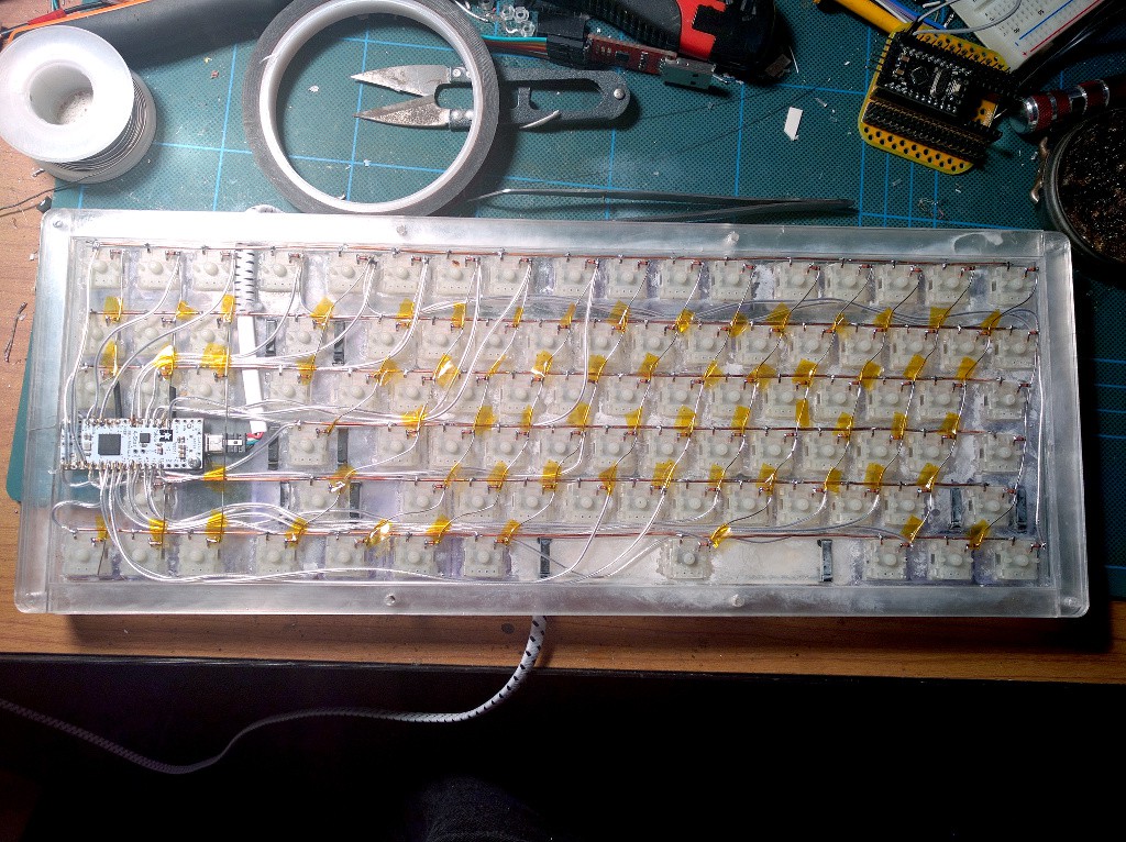 distant raven
 covert blaze
Is it necesary to have thicker routes for +5 volt?
covert blaze
Is it necesary to have thicker routes for +5 volt?
Depends on the current requirements
And copper weight
distant raven
Relationship between PCB Copper Foil Cross-Sectional Area and Maximum Current Carrying Capacity and Temperature Rise. Also introduce elements Determining Maximum Current Carrying Capacity.
covert blaze
The circuit takes a voltage pair on CN2 and a another on CN3 measures it using instrumentation amplifier setup
And outputs to CN4
distant raven
Standard outer copper is 1oz, inner copper is often 0.5oz
That matrix gives a pretty good idea of what you can expect I think
covert blaze
Wonder if I can easily determine current usage of my circuit
distant raven
I’d go off what the data sheets give for I max
since most components are in parallel, you should just be able to add the max current for each device together
In many cases, you are regulated by the power supply element like a DC-DC converter or a LDO
Common LDO have ratings at 5V for about 500mA up to 1A
covert blaze
Thanks for the help I'll get an estimate on power consumption. Then use that matrix
distant raven
👍🏻
distant raven
Whoops lol
covert blaze
Should I only do copper fill on one side of a 2 layer pcb?
supple pollen
You can do both sides, I often do. It's basically free shielding.
covert blaze
Yeah that is what I was thinking
Well there it is, no idea if it'l work yet. But hey that is half the fun
 worldly schooner
What's the vertically-mounted guy over there?
covert blaze
L7905
worldly schooner
He seems like he might need some heatsinking.
covert blaze
Unfortunately can't find him in surface mount
He probably will yeah, hence why he is on the edge. Planning on making aluminium case so will mount him to it
supple pollen
I suspect your circuitry doesn't draw enough current to require heatsinking with that TO-220 package. There are surface mount versions available, but you'd probably have to add some copper area and thermal vias for heatsinking.
worldly schooner
Yeah, there should be a DPAK form factor for it, if that's your preference.
covert blaze
I already have many ideas for a V2, but first got to see if this one works
worldly schooner
If you plan to mount it to chassis, I'd nudge that footprint closer to the edge of the board a bit. I don't know if you can get it perfectly flush, but you probably have some room to get closer.
covert blaze
Yeah I see now there is quite a gap, I'll move it a bit
supple pollen
If your current draw is low, you could use a "rail splitter" type IC like TLE2426 and a single 9V battery to get plus and minus 4.5 volt rails.
covert blaze
I was looking at premade solutions for the negative rail
Most were stepdown converters
And I can be wrong but they can be noisy
supple pollen
Yes, there are various switching converters available too. The "rail splitter" notion is an analogue solution which involves deriving a voltage midway between the input voltage positive and negative. Then you define that midway voltage as your zero volt reference, so 9V becomes +4.5V and -4.5V.
heavy jasper
There are also negative-voltage LDOs, so if you need a low-noise solution for a negative voltage from a non-battery-powered source, you can do a switching regulator to get the negative voltage, then post-regulate it with a negative-output LDO.
covert blaze
Was considering it, but didn't know if switching regulator + LDO would be still more efficient than just a LDO.
Ti has a switching regulator that can make +15 and -15 rail so I can then regulate with ghe LDO.
supple pollen
Generally yes: a linear regulator (including LDOs) dissipate the current through them times the voltage drop. So a 5V linear regulator running from a 9V source would dissipate the current through it times 4 (volts).
covert blaze
Well in reality I think the circuit is really only going to draw a few mA, think a pair of 9Vs are going to last a very long time
covert blaze
Anyone that can maybe shoot a quick look at my schematic to see if anything is terribly wrong before I order it from China
Positive and negative LDO to make +-5V rails, and then basically 2 instrument amps with a 2.5 voltage reference for offfset
 rapid slate
Hey there PCB design channel.
I'm looking for a textbook or a website, or even the proper language (search words) for getting started with this.
I made a pcb with Eagle to act as a flight computer, but it was just putting traces onto a pcb and through holes that we soldered premade breakboards into. Boards like a Teensy 4.0 and a BNO055. This was fun and I learned a lot doing it, but I want to try something a bit harder with more components so I'd like to learn how a microcontroller board like the Teensy, can be made. Do you have starting suggestions? Right now I'm watching videos from Predictable Designs.
I'm also reading an instructables and making notes about different components that need to support the MCU.
worldly schooner
If you want a real-world example, the RP2040 hardware design guide goes into the design process of the Raspberry Pi Pico. It's by no means a Teensy, but it gives you an idea of the concepts and thought process that goes into designing an MCU.
https://datasheets.raspberrypi.org/rp2040/hardware-design-with-rp2040.pdf
rapid slate
Thank you kindly.
covert blaze
The RP2040 has a glorious design manual
Next project will be to make a custom RP2040 breakout board for myself
worldly schooner
From there, you can consider your own applications and decide on your own core, peripherals, and supplementary circuitry to match your needs.
rapid slate
Oh cool, so the off the shelf MCUs have Low dropout voltage regulators to reduce the current. So if I want my pins to be able to output at a higher voltage to run larger servo motors to operate valves or control stabilizers, I can have the overall board have a larger power supply with the dropout regulator.
worldly schooner
Well, it's not always that simple. You also have to make sure that the chip itself is capable of the current you want to use, or add extra circuitry to separate chip logic from your power.
tough matrix
covert blaze
The RP2040 has a glorious design manual
It is a worthy goal, but of course you know that there are already quite a few RP2040 breakout boards - from established companies like Adafruit or Sparkfun, and from many makers - like arturo182 (aka solderparty) and our own @distant raven
 twilit mango
There are older versions of it on GitHub, available, compiled. But the latest version is not free, no.
 radiant wolf
You can also compile from source
covert blaze
tough matrix
It is a worthy goal, but of course you know that there are already quite a few R...
Well it's just practice. The idea is to build familiarity with the chip and its design constraints. And then to use that knowledge in purpose built PCBs.
 merry narwhal
Anyone know what these pinouts are
and if possible a circuit diagram for this d flip flop
 heavy jasper
What's the context of this schematic? Is it possible this sub-block is being defined elsewhere (given that e.g. it doesn't list pin numbers for an IC).
(and can you zoom out a bit so I can see what's connected to those inputs, which may give more of a hint)
With a bit of google-fu, it looks like this is part of a counter IC:

So it may or may not be available at this level of abstraction directly as a chip.
silk lark
@worldly schooner fritzing is still free and open source, if you log in on the forum you have an option to download it free
merry narwhal
yeah its apart of a 4516b counter
i like the design since it includes parallel loading and im just comfortable with that design
@heavy jasper Also thank you for taking the time to help me i greatly appreciate it
 heavy jasper
You can probably make one of these elements for yourself with something like a 74HC112 (JK flip-flop with asynchronous set and reset)
plus some glue logic to turn preset enable and parallel in into said set/reset lines
merry narwhal
And it would probably work on that diagram above?
heavy jasper
Timing issues aside, theoretically yes if it has the same truth table.
heavy jasper
At least a more modern one, by the looks of it: https://www.onsemi.com/pdf/datasheet/mc14516b-d.pdf
If you're looking for DIP packages... availability will be generally limited
merry narwhal
nah im not looking for an ic to buy
looking for a diagram to make up
seems like a weird request lol
ahahah im back to this again. Whats the diagram for the flip flop
heavy jasper
That sounds like an exercise left to the reader, to me.
(See if you can figure out a way to do it, build just one, and see if it matches the truth table, iterate if no)
merry narwhal
hmm yeah i will have to look into it
not too comfortable with making flip flops with presets
but anyway thanks for the help
worldly schooner
Has anyone used JLCPCB for component sourcing? I was wondering if I could get a bag of resistors and capacitors through them from LCSC with a PCB order, while sourcing my other ICs from Digikey...
covert blaze
I ordered few days ago
Waiting on delivery
Prices were significantly better than Mouser. So I hope it works out
 lament vapor
atmega32u4's datasheet asks for a pair of 22ohm resistors in series with the D+/- pins. but apparently I only have 20ohm resistors on hand. how critical is the resistor value in this case?
worldly schooner
lament vapor
atmega32u4's datasheet asks for a pair of 22ohm resistors in series with the D+/...
2 ohms difference isn't going to prevent it from functioning, and I wouldn't worry about it breaking anything. If your device has some behavior that might indicate unstable signal, it's not too late to replace it then.
Does anyone have any experience with USB-C termination? I want to build a keyboard that can draw USB3-level currents to power a bus-powered hub, but I'm not sure how to best terminate the CC pins...
distant raven
worldly schooner
Does anyone have any experience with USB-C termination? I want to build a keyboa...
Using pull down resistors on CC sets the current.
Usually 5.1k are used but let me find the table that describes the values and with they set for PID control
5.1K will allow you to draw a lot of current on USB 3 compatible ports
10k is good for 3A, 20k for 1.5A, etc..
tough matrix
worldly schooner
Has anyone used JLCPCB for component sourcing? I was wondering if I could get a ...
do they do that?
I mean, you can order PCBs from JLCPCB and components from LCSC, but these will be two different orders, shipped separately
distant raven
Obviously the combo of PU and PD on the entire connection will be the ultimate determination of current capacity on a USB bus
distant raven
Also, this might be helpful https://forum.digikey.com/t/simple-way-to-use-usb-type-c-to-get-5v-at-up-to-3a-15w/7016

Engineering and Component Solution Forum - TechForum │ Digi-Key
What I’m writing about today is a simple way to get 5V at up to 3A, power supply permitting using the USB Type-C standards for current sinking end devices from just two resistors on the USB-C connector on your end device, otherwise known as Upward Facing Port (UFP) This communication goes both ways, USB Type-C standards also has a specification...
covert blaze
tough matrix
do they do that?
I mean, you can order PCBs from JLCPCB and components from LCSC...
They do combined stuff now, can order parts along with your PCB
I got the option of doing it when I ordered
tough matrix
interesting. I didn't see it with my latest order - where do they show this option?
 brisk hearth
Is Kicad or EAGLE easier to learn?
silk lark
yes
 rocky quest
Order today, ships today. SMD291AX50T3 – Leaded No-Clean Solder Paste Sn63Pb37 (63/37) - Jar, 1.76 oz (50g) from Chip Quik Inc.. Pricing and Availability on millions of electronic components from Digi-Key Electronics.
is this good solder paste
 toxic patrol
I'm designing a PCB and found a chip I need from TI. It uses an nFBGA 36 pin ZEC package, and I've never soldered BGA before...
Since I'm the one making the PCB, I figured maybe I could put a small hole under each of the 36 pins (like you'd see in through-hole soldering) so I could essentially fill each hole with solder from the back to attach it, would this work?
Only issue I can see is it would be hard to get the traces out from the center pins w/ the holes there
worldly schooner
rocky quest
https://www.digikey.com/en/products/detail/chip-quik-inc/SMD291AX50T3/5130159?s=...
Looks fine, it is leaded so make sure to use a fume extractor and/or proper ventilation.
worldly schooner
toxic patrol
Since I'm the one making the PCB, I figured maybe I could put a small hole under...
The size of those pins make for really small holes that I'm doubtful you'll get solder through. That technique is suited to soldering ground pads for something like QFN, not BGA pins. I would just invest in a cheap reflow setup instead, if you can't get away from BGA.
Use solder paste and a stencil to solder all the tricky QFN/BGA chips on one side, and take a hotplate to solder them all down. Then, you can freely hand-solder all the passives on the back as needed.
toxic patrol
I'm looking at the TMUX646 from TI. It's only offered in that package, and there's currently 10 in stock (I'm ordering 7). I'm sitting here in the cart really debating it...
I'd have to get that equipment you just mentioned as well
worldly schooner
Solder paste is cheap, and you can get a taping knife to spread it from your local hardware store pretty easily. Stencils are offered by every PCB manufacturer you're likely to order them from, so the only difficult equipment would be the hot plate.
Actually, hot air is an option too, now that I think about it.
toxic patrol
I have access to a heat gun
supple pollen
rocky quest
https://www.digikey.com/en/products/detail/chip-quik-inc/SMD291AX50T3/5130159?s=...
It's T3, which is fairly coarse grained. It should work okay with stencils, but would be difficult to use with (say) a syringe
toxic patrol
It has been ordered
worldly schooner
Oh solder paste isn't even needed
The balls in the ball grid are solder

BGA Soldering & Repairing Guide and Tutorial - Learn how to Solder Ball Grid Array (BGA SMD Chip) by Hand Soldering Using Hot Air and Solder Balls.
Flux paste...
Crud
Well, it's certainly doable with hot air though
Paste does help make the temperature curve less strict, but flux looks like a must-have
And preferably one that isn't straight liquid.
BGA for hobbyists. Is it even possible? - Page 1
Does anyone have experience with any of the ~$50 hot air stations on Amazon? I thought a hot air station designed for soldering would be more expensive than that...
supple pollen
I regard the amazon stuff as particularly sketchy, even if someone else bought an "identical" item and had a good experience with it, their "equivalent merchandise" policy means you could get a completely different one.
toxic patrol
shoot
this thing is 2.45mm x 2.45mm x 1mm
uuuhhhhhhh
Shoud I try to cancel the order??????
worldly schooner
The chip?
worldly schooner
I mean, depends on your confidence.
toxic patrol
Ball diameter is 0.25mm
As someone who has only soldered through-hole, do you think I can pull this off?
worldly schooner
The smaller the chip, the easier it is to heat.
As long as you have the flux and a properly designed pcb...?
Wait you've never done SMD before?
toxic patrol
I mean, I guess you're right
There'll be SMD on this thing I'm doing
It's time to leard all the solders!
woo!
cries
worldly schooner
At that point, you might also consider paying for PCBA
If you can get a fabhouse to put the hard one on for you, you can probably handle passives on the back?
toxic patrol
I used JLCPCB for my latest (and first) PCB, and was thinking of using them again. I don't think they offer that
This chip is just 6x6 balls in a straight grid, not sure about passives or anything
worldly schooner
They do, but you're restricted to their supply.
toxic patrol
And they don't offer BGA I don't think
worldly schooner
Passives refers to all the resistors and capacitors, etc.
worldly schooner
Hence why the through hole method you tried to suggest would've been a catastrophe LOL
toxic patrol
yeah...
worldly schooner
It's fine, you should decide for yourself if the risk here is worth taking or not.
To my knowledge, the harder part isn't the actual assembly, but the design and layout.
6x6 shouldn't be too bad, but if you're not confident, I'd look for a different chip for now.
toxic patrol
Well, I gtg for now... I'll return in a few hours to keep working on this
If I did order from a site with assembly, I'd still have to cancel my order, right?
worldly schooner
Probably? I'd recommend it
toxic patrol
So... in your opinion, what would you do in my situation...
worldly schooner
Cancel, get a PCBA quote, and decide from there
toxic patrol
k
worldly schooner
What kind of chip are you trying to use, anyways? I find it strange that a particular chip with less than 50 pins isn't available in alternate packaging...
Especially from a manufacturer as large as TI.
toxic patrol
MIPI multiplexer
toxic patrol
worldly schooner
Cancel, get a PCBA quote, and decide from there
Also, TI said they couldn't cancel it
Which is annoying seen as I ordered it like an hour before I tried to cancel
Oh well, good luck to me I guess!
I'll figure it out
supple pollen
We all seem to accumulate a stash of chips we'll never/can't use...
sweet inlet
@unreal flax @supple pollen @heavy jasper thank you all for helping me with my pcb design / soldering! Got t fully functional yesterday:


 distant raven
Very nicely done
sweet inlet
@distant raven thank you too! IIRC you recommended components to me, ended up using your recommendations!
sweet inlet
The shape was copied from the one that came with the keyboard 🙂 lots of fun laying out traces
I assembled it, took 2-3 fixes to get it working.
distant raven
Oh wow, nice job!
toxic patrol
I'm back again with the camera switcher nonsense I'm sure you're tired of hearing about. Is there a downside of leaching the 3.3v and ground for the multiplexers from the cameras, as opposed to a dedicated power and ground input?
worldly schooner
Would depend on the design of the source you're trying to pull from and the sensitivity of the chips you're trying to power, but if it's insufficient you may get intermittent voltage dips.
Are you trying to make a Raspberry Pi camera switch?
Power for the Pi cameras come from the RPi, not the camera module. The regulators on the Pi camera handle conversion to 2.8v, 1.8v, and 1.2v.
toxic patrol
The RPi cameras run on 15 pin ribbon cables. 1 of the pins us 3.3v power from the Pi to the cameras. Another 4 pins or so are all ground. My options are
A) Hook multiplexer power up to that 3.3v line for power
B) Use a dedicated terminal block for the 3.3v power and ground
The pinout for the cameras is on Arducam's website
I used the power leeching design in V1 (I've posted the schematics for that one before if you search from:Zman has:file)
worldly schooner
I would expect the Pi's 3v3 is pretty stable, though I'm not sure how much current is being pulled into your chip compared to how much the ribbon cable can carry. Do you know how much your multiplexer chip pulls?
toxic patrol
I'd be using the Pi's 3v3 anyways, its just a question of pulling from the camera cable vs the GPIO pin (although I'm fairly certain they're the same but idrk).
Here's what I got current-wise

(there's 7 muxes, model: TI TMUX646)
supple pollen
so 30 * 7 = 210µA? That doesn't seem like it would be a problem.
 limpid nest
I need to transmit ~15 mA @ 5V over a distance of up to 15 feet in order to toggle a relay on/off. I need connectors (and cables) to connect the 5V and GND from my main enclosure to a number of sub enclosures. They need to be (relatively) inexpensive and water/dust resistant. Would IP rated barrel jacks/plugs be an out of line choice?
oh and also not require an expensive crimp tool
distant raven
limpid nest
I need to transmit ~15 mA @ 5V over a distance of up to 15 feet in order to togg...
Why not use an ESP32?
limpid nest
wifi?
distant raven
FeatherS2 from Unexpected Maker can do battery power, Wifi, etc..
It’s a great option without 15ft of wire
limpid nest
ah interesting, let me give some background. I'm currently retrofitting/refurbishing a university team's capstone project. In this iteration of the project I'm a bit limited to just getting what they did working again, as it has to be done fast. Later on I'll be doing my own design and I can do some groovy stuff. What I'm working on is a "brain" box to send the control signals to the 12 sub boxes. I'd need 13 feathers in that case right?
distant raven
Well, featheS2 is one example, but they have cheap ESP01 modules which could do that cheaper if you need a lot
limpid nest
another constraint is it needs to be easy to debug and repair without me around. The company this is for will have lots of folks with electrical experience, but almost none if not no people who can program or debug wifi issues
But I do love the idea of no wires
distant raven
Okay, so picking something that can do circuitpython might be a really great option
limpid nest
yeah, right now we're working with a pi 3 A+ since we need to play music. It's overkill to the extreme for what we need but I want to find a way to use the hdmi out
distant raven
~$4
There is a circuitpython build for it. If you need batter, Adafruit sells a battery backpack that could probably power that
limpid nest
oh we're switching AC power, so power isn't a problem. I kept the pi as the board for this since I knew I could do circuitpython with it
distant raven
Okay, yeah just one of those Wemos S2 mini
limpid nest
as the control unit?
limpid nest
I'm relatively comfortable with upython as well
distant raven
And debugging is visual through repl so easy for future maintainers
limpid nest
I'll definitely include wifi as an option in my presentation for future versions of the product!
distant raven
Plus Wifi so you could set it up to log to Adafruit IO or something like an mqtt server
limpid nest
Any thoughts on IP rated barrel jacks for now? Seems like a cheap way to route two signals
distant raven
I’ve never seen barrel jacks used for data before, but they have where you can use power outlets for data so probably possible
limpid nest
hmm I'll keep looking, keep that in my back pocket
supple pollen
I normally use automotive connectors for things like that. They often seal nicely when mated.
limpid nest
do you need special crimp tools?
supple pollen
It depends on the connector. Some work fine with generic crimp tools.
 limpid nest
would I search automotive connectors on digikey?
It would be nice to be able to mount them in my plastic enclosure
supple pollen
DigiKey should carry stuff like that. The pictured ones are just the ones I happened to find an image of, but those are MX80 connectors, which use a thousand dollar crimper, so they're not the specific ones you're looking for.
supple pollen
Connectors, Interconnects -> Rectangular Connectors - Housings, then under features, select all the "waterproof" and "weatherproof" options.
limpid nest
noice!
thx
how does one tell if a connector requires expensive tools if it isn't called out in the datasheet?
contact the supplier?
supple pollen
It can be tricky. Some contacts work fine with a generic tool, some don't.
limpid nest
shucks
heavy jasper
These folks tend to have a decent variety of stuff, and frequently make their connectors with solder cups instead of crimped connectors, which can be easier to assemble w/o nice tooling: https://www.switchcraft.com
In general, for any crimp you might do, order extras, then clamp the contact to a table and try to pull the wire out to see how much force it takes. Usually smaller connectors are a bit easier to get right with generic tooling; the biggest problem for fancier connectors is not accidentally deforming any geometry that the housing relies on. For anything larger (~14-16 awg is my rough limit), having the correct tooling or at least tooling with appropriate leverage (think foot-long handle ratcheting crimpers) becomes a big deal.
tough matrix
I've finally found a system of storing loose SMD components I am happy with: modular boxes + 3d printed trays: https://www.thingiverse.com/thing:4965344

This is a tray to hold strips of modular storage boxes for SMD components. These boxes are available from a number of vendors, e.g. Adafruit: https://www.adafruit.com/product/431. They are also available on Amazon and AliExpres (search for "SMT mini storage box")
The tray allows to neatly organize large collection of such boxes without connecti...
 empty hollow
What would you recommend for bypassing capacitors for a simple pcb with a couple of sensor chips and serial-ttl chip. I am making a hat pcb for pi zero to be put inside a neopixel lamp.
mystic crypt
tough matrix
I've finally found a system of storing loose SMD components I am happy with: mod...

That's my method and besides being a little janky it is nice since it can handle many values with a small footprint
fervent lance
Looking at the datasheet for the MCP23008 I2C I/O expander, pins A0-A2 , RESET and INT are unused but need to be biased externally. How do I do this?