#help-with-hw-design
1 messages · Page 48 of 1
 unreal flax
 rustic linden
Adafruit don't make it, and it doesn't seem to have anything but the datasheet so I feel like I'm just gonna have to figure out a way to add like... dimension constraints and such, idk
welp there goes my afternoon
unreal flax
Ah, I see. If it's chip or standard part you could check sites like UltraLibrarian to see if there is a footprint package available for it.
rustic linden
It's an RGB LCD 😢
rustic linden
I managed to nicely do it up though!
 supple pollen
Nice! Making your own custom parts is a useful skill.
rustic linden
I made a board that slips on the back of the LCD, and it mounts using the pinheader and the screw locations in the LCD (not all of them, though)
supple pollen
So it fits on the LCD like a backpack?
rustic linden
yeah
I considered calling it a backpack at one point actually
it's very much a specific use case though, so it's not like anyone but me would need it
 carmine scarab
Until someone sees you using it and asks "Where did you get that??!!?!"
rustic linden
i mean, i plan on bringing it to PAX in October
supple pollen
Sounds like a nice design
 silk lark
another samd21 board

pin-compatible with Arduino Pro Micro, so I can upgrade some old projects
 fast tundra
@silk lark you're really all about using the bare minimum caps 😂
silk lark
@fast tundra it's a scam of the capacitor manufacturers to get us to buy more
I mean, what do I care if the power is filtered before the regulator?
fast tundra
😅
 distant raven
Haha 😂
 pearl tapir
silk lark
<@!545388582794166298> it's a scam of the capacitor manufacturers to get us to b...
pearl tapir
silk lark
<@!545388582794166298> it's a scam of the capacitor manufacturers to get us to b...
Possibly the regulation loop will be unstable. It needs to be verified on the data sheet but it might oscillate. I've seen it happen.
 south gazelle
silk lark
I mean, what do I care if the power is filtered *before* the regulator?
south gazelle
silk lark
I mean, what do I care if the power is filtered *before* the regulator?
In fact if you look at the schematics of the Adafruit M0 Express, it really has a minimal set of caps. In fact there is not a single 0.1uF decoupling cap on there.
distant raven
Yup, M0 usually just uses 1uF caps
rustic linden
I'm very proud of the last PCB I designed to be fabbed
 vocal abyss
Hi there, I am wondering if anybody can help me understand making a ground and voltage plane in my 2 layer PCB. Currently in my layout, I have tracks going from my component pads to where I want them to connect to their respective plane with vias. In KiCAD, am I able to trust that the whole plane is electrically connected when I do this and regenerate the plane (the rats nest connection indicators disappeared). Thanks
 compact lotus
Hello <@&741361254035095602>
Is it possible to auto-generate using a KiCAD add-on or a different tool a pinout refrence ( similar to the one in the picture ) ?
 distant raven
Hey there @compact lotus there isn't a straight forward way to make graphics like this
I think a lot of people who make these use either Inkscape or Adobe Illustrator
 tough matrix
I saw this video: https://www.youtube.com/watch?v=ndVs1UvK6AE
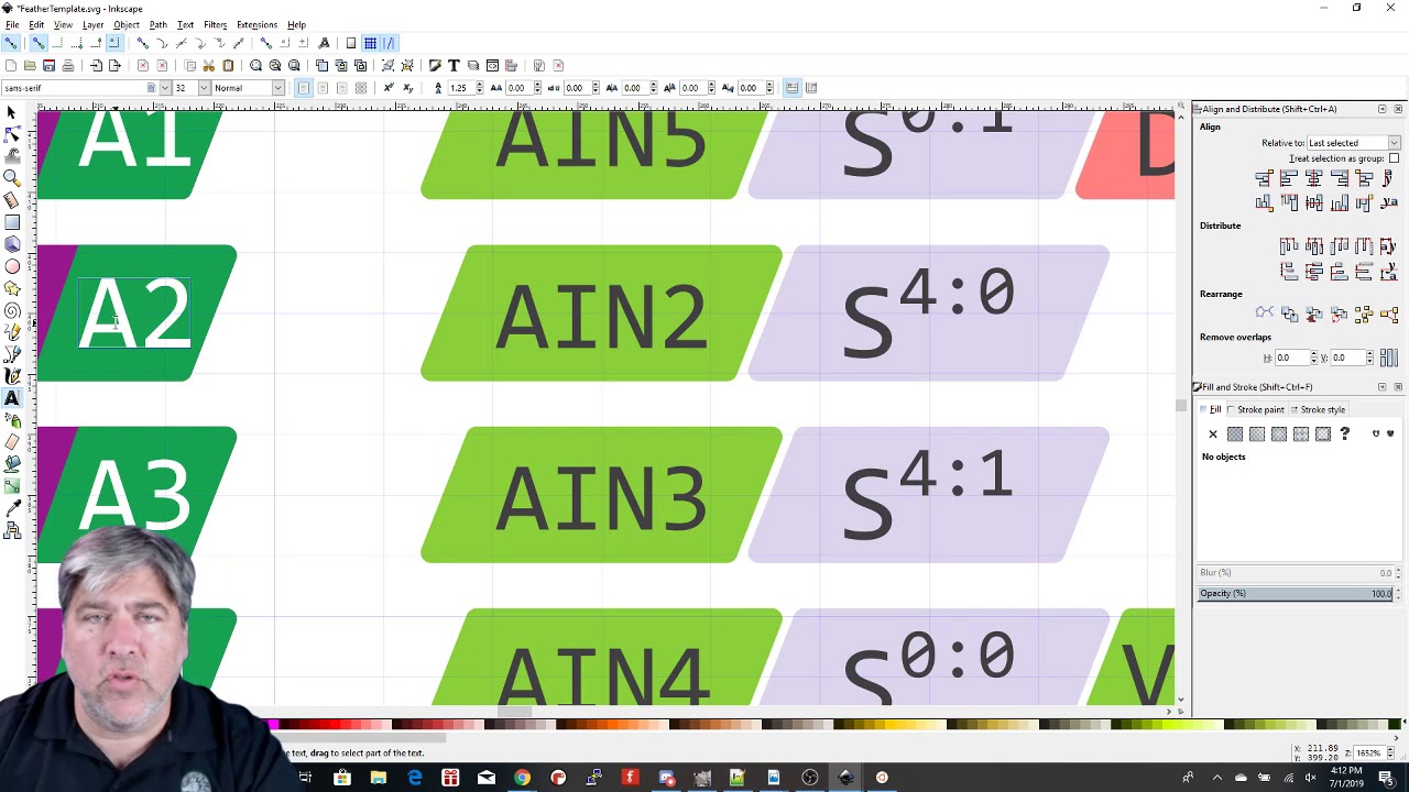
This is a rough walk-through on how to use the template I made Adafruit.
The template is at:
https://github.com/ATMakersOrg/HoldingArea/blob/master/FeatherTemplate.svg
compact lotus
Yes I already found the same video
I was hoping to find a python script or an app that can automate the task
I posted the same question on KiCAD forum
rustic linden
I don't know if anyone has made it yet but... it seems like an interesting project I'd totally see myself doing, at least just in a basic sense at some point
compact lotus

KiCad.info Forums
Hello Is it possible to auto-generate a pinout reference ( similar to the one in the picture ) using a KiCAD add-on or a different tool ?
Here is the link to rhe post on KiCAD forum
One of the users found an article on hackday
That is interesting

Graphical datasheets that describe pin functions and other information about Single Board computers are very popular. However to generate them is a tedious process requiring the use of graphical art software (Inkscape, etc) and is not repeatable. So, if a board changes due to a revision, or pin-out information needs to be revised, the file nee...
I will check it later
tough matrix
nice
would be interesting to see how it works in real life
 unreal pollen
Anybody know how a sensor like this could be mounted to a pcb or better yet, use something like a ribbon cable to connect it?
Do I need to be looking at this instead?
silk lark
it's a through-hole part, you just make holes in your pcb, put those legs through them, and solder them
unreal pollen
Is there a way to 90 degree mount stuff like this?
As in perpendicular to the board itself
distant raven
unreal pollen
Is there a way to 90 degree mount stuff like this?
If you make a carrier PCB and solder it into a plated slot on your main PCB
unreal pollen
Is that in any way a common thing for fab/assembly shops to put together?
distant raven
Depends on the contract manufacturer
But special things like that usually cost extra
 inland jungle
solder it in normal, and then just bend it
 plush root
Hi, I have experience with electronics from undergrad classes. I want to learn a new skill now that the semester is over. I am planning on building a PCB this weekend and would like a mentor I could ask a few questions/get on a call with. I am going to be working on Eagle so if you have experience please add me!
distant raven
@plush root it’s better to ask your questions here so other people can learn too 🙂
Just post them and most everyone here can help you in some manor or another
 feral mulch
I want to use a part that's (seemingly?) only available in an LGA package
does this seem possible to hand solder?

I've done ones where the pins are on the bottom and on the edges
but these are only on the bottom :(
 long wraith
You should be able to do it with solder paste and a reflow station
silk lark
or a hot plate
I finally finished converting the Chocolad keyboard to CircuitPython. Had to make Pro Micro-compatible SAMD21 boards.

 vapid grove
Oh, cool!
silk lark
I'm using CircuitPython code here
vapid grove
Ok
rustic linden
Anyone have any suggestions for a PCB design software for the Raspberry Pi? My regular PC is playing up and I have a Raspberry Pi laying around to use
 heavy jasper
I think kicad may be your only option for something that natively runs on arm64 linux.
or a web-based tool
rustic linden
thank you! luckily im actually familiar with KiCAD
 vapid lark
anyone in here who works in easyEDA who can help me look over my new revision board? apparently i screwed up the first revision for some reason when power the LED strips (all 8 strips x 32 LED per) the ESP32 just "dies" as in i lose connection to it and wifi wont turn on again!!! so i made some changes to the board going from 2 layer to 4 and fixed some footprint errors i made (they were way to small 😅 ) and also changed the polarity of the DC jack 😛 i was following a british guy on PCB making and he put center negative and without thinking so did i! 😛 but i've changed it now!
i would love some help so that there is no mistake on batch 2 when i order now! :/ (all 5 boards i have now are useless because of that power mistake)
heavy jasper
@vapid lark I'm willing to take a look if you can post the link to it here and are willing to have the design and feedback be public.
(I prefer to do these sorts of things in an open forum so that others can learn as well)
tough matrix
@compact lotus (and everyone else interested) did you see latest LadyAda show - she talks about automatically generating pinout diagrams and board definition files from the same source:
https://www.youtube.com/watch?v=tAKLygjfO_U

This week's Desk of Ladyada is a little light on hardware, as we spent some of the weekend outside and the rest on some software hacking! We used to get very nice pinout diagrams made for our boards by a fellow named Pighixxx. They ended up doing a crowdfunding project that didn't work out and they stopped replying to emails. We like having pino...
long wraith
She be magic!
distant raven
 long wraith
OwO what's this
distant raven
An FPGA feather that I don’t have the parts to build
long wraith
Uhoh... Well, at least you have the board!
distant raven
Yeah, need to just back order the parts
long wraith
Completion soonTM
distant raven
Coming Soon™️
long wraith
Hehe
 gaunt cedar
hi - I'm designing a board that will usually be powered from an SAO or coincell. I'll manage which with a simple slide switch. I'd also like the option to throw a USB on the board for easier code hacking and I'm not sure how to handle that third source of power. the usb will go through a 3.3 voltage regulator but I'm stuck on how to handle this. looking for any suggestions
my electrical circuit ignorance is going to show here. could I feed a 3.3v bus from both a coincell and the output from the usb voltage regulator or do I need to isolate those two voltage sources from each other?
distant raven
Usually you want to block voltage from usb going to the battery, but if the battery is on the 3.3V side, you could just disable the regulator when a coin battery is present
Many regulators have enable pins
gaunt cedar
thank you @distant raven I'll look into this
heavy jasper
Make sure that your regulator also has a reverse-blocking feature when enable is off, or put in your own reverse-blocking circuit. many regulators are not designed to prevent back-powering from their outputs to inputs, and you could end up back-under powering your USB.
distant raven
heavy jasper
Make sure that your regulator also has a reverse-blocking feature when enable is...
Most USB applications recommend Schottky diodes anyway, yeah? I know I use them everywhere
heavy jasper
If you can stand the overhead, works great.
I actually tend to also put diodes at the inputs of all my LDOs unless they're specifically back-power rated
When you remove power from a board, if the input rail discharges first before the output rails do, then the LDO can possibly get damaged with uncontrolled reverse current flow to keep the rest of the circuit up.
 unkempt remnant
Testing some ideas for Itty bitty teeny tiny battery contacts for zinc air batteries partially potted in silicone. All I can say about my first try was that An Attempt Was Made. Hopefully these work better


Size tests in silicone. Eventually the battery flex board will be cast into this mold
unkempt remnant
Fingers crossed that I can make the zinc air batteries work. That power density 👌 and you can source like an order of magnitude more current than lithium coin cells (where by "an order of magnitude" I mean 10-20mA... it's not so much that zn batteries are high power as that you just cannot get any significant amount of juice out of a typical coin cell, they're not designed for it)
even if I could fit a miniscule pouch battery into the space I have available, I would really rather go with something that I can buy at the grocery store in an emergency
supple pollen
I had no idea you could get that much current from a zinc-air cell.
unkempt remnant
I was pretty surprised too. Not sure how it will do with a continuous load, but we'll see.
 elder peak
I didn't zinc so either, but I guess you can.
distant raven
I suppose you could use it if it metal the requirements
 rocky quest
is the ms5611 better than the mpl3115a2 or is it the other way around
silk lark
better for what
rocky quest
silk lark
better for what
like the overall better barometer
silk lark
if one of them were just better, why would they still be selling the other one?
unkempt remnant
speaking of zinc-air batteries, here's a power supply dilemma. so zinc air batteries can start out sourcing like 40 mA (!) but as it runs out of air, the current decreases fairly significantly over several seconds until you give it some time to rest.
wonder if there's a simple way to switch between batteries every few seconds?
unreal flax
If you have multiple batteries, it's probably more efficient to run them all at a lower current at the same time.
unkempt remnant
true, but zn-air batteries have some particular quirks
I'll need to see what max current they can sustain. they can definitely source much more current when they've had a chance to refresh their air supply, thoug
so depending on how that works out, I might be able to get significantly more current by switching between batteries every second or something
thte nice thing is that the batteries are small enough that I could fit, like, four into the teeny tiny space available
the graph in section 5.4 also shows drain rate, which even for bitty 312 cells can go up to 13mA or so
gaunt cedar

follow-up from yesterdays question regarding multiple possible inputs. using this schottky diode on the inputs and landing on the same vbus I believe this will accomplish what I need. any examples I've seen are only 2 inputs and not a third. does this look like a workable solution? I've got a really rough route as well to see if I'm doing it correct.
 plush root
I am looking for a dc power connector for my pcb, does anyone have a specific part (both female & male) they suggest? I am unsure about diameter sizes (do they even matter?) . I also prefer something that is made in US that is readily available
gaunt cedar
are you familiar with looking up items on digikey? @plush root
plush root
I have never used digikey but I have looked at Newark Electronics, do you think digikey has better selection? @gaunt cedar
gaunt cedar
looking at newark, i think the selection at either is good. I was more checking to see if you're familiar with way to look up items to narrow down your scope. im more familiar with digikey but they both show in stock items, quantities available for immediate ship etc.
to answer your question better - if you can define your requirements a bit more that should get you closer to what you want. through hole, surface mount, etc etc
searching for barrel plug on either site and then applying filters to narrow down what you are after would be my suggestion. I dont have an answer to a catchall favorite dc connector tho sorry
plush root
oh I see. I am pretty new at it but I am getting better at filtering through as there are aloooot of parts. I got worried about choosing something that won't fit as it seems to be a common issue with barrel connectors. And I was mainly wondering if someone had some go-to parts that fit and work well. I appreciate your suggestion thou @gaunt cedar
distant raven
My only issue with Newark is there are a number of things that they carry that are just a lot more expensive than mouser and Digi-Key
inland jungle
I prefer the filtering on Digikey, especially since you can sort on more columns (like in-stock qty) compared to Mouser.
heavy jasper
Specifically sorting for "made in US" on connectors is going to be difficult, and if you're not careful you'll fall into the trap of military/aerospace connectors. They're very very nice admittedly, but also $$$. You might have luck with these folks: https://www.switchcraft.com/
Not sure what voltage of DC you're looking for, but if you can find a matching wall wart power supply, usually best to match that.
vapid grove
Do I get it right that SAO is a “standardized” badge expansion connector or it is something else?
supple pollen
@plush root The AdaFruit PartFinder is useful for finding common components like that. Here's the power connector page, which gives Digikey and Mouser part numbers too. http://www.ladyada.net/wiki/partfinder/powerconn
gaunt cedar
vapid grove
Do I get it right that SAO is a “standardized” badge expansion connector or it ...
tough matrix
supple pollen
<@!722675146917150740> The AdaFruit PartFinder is useful for finding common comp...
haven't seen that site before. Cool idea, but it looks like it hasn't been updated in a while - e.g. there si no mention of JST SH 4-pin, aka Stemma QT, connector
Maybe we coudl clone it and have a community- maintained database of "our favorite parts"?
supple pollen
It does show a modified date of 2016. It would be cool to have a crowdsourced version that was reflected into nice neat web pages like that.
tough matrix
Making wiki page on github is easy. But maybe there is already a DB like that? anyone knows?
plush root
@supple pollen this site was very useful, thanks for sharing! @tough matrix we should definitely have this! I feel so much more comfortable buying a recommended/reviewed product
distant raven
Prototypes and some production panels
 tough matrix
plush root
<@!348911944486486016> this site was very useful, thanks for sharing! <@!3206659...
tough matrix
plush root
<@!348911944486486016> this site was very useful, thanks for sharing! <@!3206659...
we need enough people willing to contribute to that - othrwise the project will slowly die...
supple pollen
You'd have to have a way to deal with different peoples' preferences too: some like Samtron, some like Berg, some like AMP, some like Molex, some like 4UCON.
tough matrix
yeah...
On a positive note, I just ordered some SAMD21G18 - the order was accepted and chips are scheduled to arrive on my doorstep in a couple of weeks.
As opposed to "some time in late August" you see on Digikey 🙂
tough matrix
yes
it was easy, thanks to Stargirl for the tip
distant raven
I’m surprised they had any available that soon
tough matrix
maybe I got lucky
They had no samd21g18a-au in stock, but kindly suggested samd21g18a-af as drop-in replacment (the only difference is range of temperatures it can work in)
distant raven
Yeah, slightly more expensive but the same for most applications
elder peak
Thanks to Stargirl, now we can be well ARMed.

 supple pollen
But ... why?
silk lark
some people like to see the world burn
distant raven
some people like BGA
elder peak
I dono, man, it makes me want to take my ball and go home
long wraith
distant raven
It’s a Cursed Board ™️
 distant raven
Maybe I’ll turn it into a curse SMT soldering challenge with associated mounting board
The mounting board will have all the IO broken out with USB, SPI flash and other necessities
All you have to do is successfully solder all the bits on the BGA board and then solder the BGA board to the carrier/mounting board
elder peak
Why do you hate people, @distant raven ?
long wraith
It's just the Advanced Insanity Challenge
If the shenanigans of that board bother you... you failed :D
distant raven
elder peak
Why do you hate people, <@!728676724522352733> ?
I was told y’all love BGA
rustic linden
what even is BGA
heavy jasper
Ball Grid Array. Where all the little dots are on the PCB, some solder would get deposited and melted into small very-similarly-sized balls. Then that's a finished part, and can be soldered again onto another board with some new solder for flux/gap-filling.
For an application like this, it's kind of just a fun exercise, but they're pretty much the only way to go when you have very high pin count soldered parts, on the extreme end think things like laptop processors:
 rustic linden
huh!
heavy jasper
(for a sense of scale, that's 1377 balls, on a 0.43mm pitch).
long wraith
Much more dense pinning than QFP!
 haughty wolf
distant raven
some people like BGA
haughty wolf
distant raven
some people like BGA
bga is necessary and nothing more lmao
supple pollen
SparkFun realized they'd need an expensive fine pitch multilayer board for their Artemis BGA MPU, but instead of making their entire board that way, they made a little carrier board that they then attached to a larger, lower cost board.

They do sell the little carrier board separately, for those who want to use it with their own designs https://www.sparkfun.com/products/15484

The Artemis Module from SparkFun is the first FCC certified, open-source, Cortex-M4F with BLE 5.0 running up to 96MHz and with as low power as 6uA per MHz.
Their writeup on the thinking behind it is informative on BGA issues in general. https://www.sparkfun.com/news/3122
Learn how we created our own SMD module using PCB tips and tricks for blind and buried vias.
tough matrix
never tried soldering a BGA... and hope to avoid it in my future life, too
distant raven
The RP Baller has a super wide pitch that’s friendly towards makers
1.6mm pitch and 0.5mm ball size
haughty wolf
i would squeeze solder paste on the pads and reflow with a hot air gun
you could get a stencil for not too much money though. they can be a pain to use sometimes though
heavy jasper
At certain volumes, even the cost of adding a hot air gun may not be well amortized; you’ll want to have an iron anyway for touch-ups. The cheapest answer I can think of is “design only with parts you can solder with an iron, then do so.”
distant raven
I use a combination of hot plate and hot air gun
I’ve not soldered a BGA part yet but I will be soon
Good hot plates transfer decently
But it’s the accuracy of temperature that is the biggest issue
Metal top, no ceramic or glass
Nothing
The heat plate I have has a metal top
The only issue with mine is the PID isn’t very well tuned
So to get the 140°C I need for my solder paste, it has to be around 165-170°C
Which is better than similar hot plates
Yes I use low temp lead free
The hot plate has a heating cycle
Yeah
I paid like $10 for a 15g syringe of NC191LT15
It’s T4 ball size
It’s from ChipQuik
Yeah, you need to be careful about it
nah, it's usually pretty well priced for syringes
it's like $60 for 250g of it
distant raven
If you got on Digi-Key you can get 35g for $26 in a syringe
I’m not sure
I use Autodesk Eagle
Eagle comes off as fusion360
And they do have a startup program
You can apply as long as you don’t design for other companies
I didn’t apply because I do work for other people
 fathom lotus
hi guys, reverse engineering a pcb solenoid driver, i've got the circuit down correct but can someone check if my understanding of how it works/what it's doing is correct? the only part i'm confused about is why r2 is pulling pin 2 of q1 high

the only thing that may be wrong here is the pinout of q1, as i was unable to find a datasheet for it so i went off what i know to be the standard/most common pinout
unkempt remnant
Interesting. I've finally managed to make the thermocouples on my reflow oven swappable, and run some profiles using thermocouples firmly attached to PCBs... turns out that my oven has a tendency to overshoot by 10-20 degrees or so. Or more likely, the copper cladding on the board has too much inertia.
(Celsius)
But with low temp solder it probably doesn't matter
supple pollen
The diode doesn't look right and you'll want a series resistor for the base
unkempt remnant
controleo 3 kit
I'll re-run its learning thingy and see if it does better after that
south gazelle
fathom lotus
the only thing that may be wrong here is the pinout of q1, as i was unable to fi...
I suspect that pins 1 and 3 from Q1 should be flipped around here, with the emitter (pin 3) connected to GND. I also think that R2 should probably be between pin 8 of U1 and pin 2 of Q1, instead of pulling the gate of Q1 high. As an other alternative, perhaps Q1 is a PNP transistor instead of the NPN showed here. The the circuit would then probably work in an inverted logic (Solenoid turns on when pin 8 of U1 is low). I think this is unlikely however.
silk lark
trying a PCB battery holder
 rustic linden
how do i design a lipoly battery charging circuit like the ones the feathers have?
I've never made a battery charging circuit, but I have a project that will need it and I can't just use a board someone else has made, cause it needs to be integrated into the board
heavy jasper
Straightforward starting point: clone the one on the feather if it works for you; the schematics are available.
rustic linden
Duh ofc they have it available
distant raven
Yeah, the mcp73831 can be tricky to get your hands on right now though
 cerulean crest
distant raven
Yeah, the mcp73831 can be tricky to get your hands on right now though
cerulean crest
distant raven
Yeah, the mcp73831 can be tricky to get your hands on right now though
Seems to be lots of stock on mouser
cerulean crest
All variants in stock from what I see, some have lower stock around 200 quantity
cerulean crest
Oh didnt go to the next page, there are 4 variants out of stock
cerulean crest
MCP73832T-2ACI/MC, MCP73832T-2DCI/MC, MCP73832T-2ACI/OT, MCP73832T-4ADI/MC best of luck 😆 chip shortage is pretty bad
cerulean crest
Im not sure what Im gonna do at work, we cannot get parts for the "legacy" product and they are selling like absolute hotcakes, I only have enough stock to get me to fall
distant raven
Dang
cerulean crest
I had to source almost every IC in the last two pcb orders from weird niche places
distant raven
That’s scary
cerulean crest
I am currently one of the largest holders of isl28635 amps in north america from what Ive seen 😆
distant raven
Off channel part sources leave a lot to be desired
cerulean crest
Indeed, making a few friends along the way however. Some places I never heard of did great work
cerulean crest
When I saw the airtags tho... "ahhh thats where all my bga nrf52832s went" 😭 . And nice, that can be a challenge
distant raven
It was a bit nerve racking wondering if I was getting legitimate ones or not
Oh dang, yeah a lot of nRF chips are gone
And a lot of STM stuff too
I’m just waiting to get my hands on the rp2040 chip but I won’t have them until mid July
cerulean crest
I was kinda surprised by the stm stuff at first, I would have thought st was gonna be right on top of it.
distant raven
I’ve got samples I working with but lead times are 8 weeks so.. a 500 pc reel won’t arrive until July so that kind of hampers things
cerulean crest
Its fine, just buy 500 picos
distant raven
cerulean crest
I was kinda surprised by the stm stuff at first, I would have thought st was gon...
This is because a ton of resellers hoarded them and are selling them marked up like crazy
cerulean crest
And a nice desoldering setup 😆 😆 😭
cerulean crest
distant raven
This is because a ton of resellers hoarded them and are selling them marked up l...
Ah makes sense
distant raven
Oh, I couldn’t buy 500 Pico for the price I’m paying lol
cerulean crest
I know 😆 Was a joke since Im finding myself desoldering from dev boards to make new pcb designs
distant raven
If I bought the Pico boards directly from RPi, I think I could get them for like $1.75 a piece
I only asked for a quote on the chips though not the actual Pico boards
Maybe I should ask
Become a reseller
distant raven
cerulean crest
I know 😆 Was a joke since Im finding myself desoldering from dev boards to mak...
I have also done this lol
But anyway
What I do know is I have 190 Samd21 chips left
cerulean crest
Is that good or bad compared to usual stock? I havnt checked SAMD21/51 availability recently
distant raven
They are back ordered most places until July or later
I think microchip direct has some same51
But by and large, a lot are sold out
cerulean crest
Indeed. I hope not too many smaller players are dying out waiting for parts
distant raven
I can see to about.. Julyish
I don’t know how things look after that
Hard to really tell
cerulean crest
Just imagine starting your own small thing right before the pandemic, you put a lot of time and money in, now you cant get parts to sell product to pay for the things you need then you're back working at walmart. Id just cry myself to sleep 😆
distant raven
I’m glad I have a nice software engineering role but I like my maker business and I’m trying hard to grow it. But semiconductor shortage was not on my pandemic bingo card
I can float my business to keep it going while things recover
It’s not ideal but it’s something o can do anyway
long wraith
Random question -- I've only ever done basic PCB design on paper or in MS Paint... Any recommendations on an easy software to start with, preferably free, that can export appropriate files to send off for production?
tough matrix
I ordered some ATSAMD21G recently directly from Microchip
tough matrix
long wraith
Random question -- I've only ever done basic PCB design on paper or in MS Paint....
Commonly used is Eagle (free for very limited use) and KiCad (free, open source)
But I think the easiest one to start is online one, easyEDA
long wraith
Cool. I've heard of Eagle, thought it was expensive XD what would classify as "very limited use"?
tough matrix
EAGLE free download is a limited version for hobbyists including 2 schematic sheets, 2 signal layers, and an 80cm2 (12.4in2) board area.
But check easyEDA
long wraith
Ah... I'd like to get into multi-layer design, and easyEDA shows that in the front page, so I think I'll start there. Thanks!
rustic linden
gosh this is confusing
I'm trying to figure out how to add a battery charging circuit to something, I'm starting with what a feather has but I'm not 100% sure on everything and the diagrams are a little confusing
cerulean crest
rustic linden
I'm trying to figure out how to add a battery charging circuit to something, I'm...
Do you have a more specific question around the schematic for the feather? Im familiar like many others here and happy to help
rustic linden
How would I go about adding a battery circuit to a rapsberry pi pico?
(assuming a battery charging circuit similar to the feather boards is even possible with a pico)
cerulean crest
Im not too too familiar with the pico, but looking at its schematic, you need a battery charger, battery input, then protection between the battery and the VSYS
Lmao, right after I sent that, there is a section in the pico datasheet "Adding a charger"
cerulean crest
Section 4.6, Using a battery charger sorry, but its adding a charge circuit to the board
rustic linden
I am blind
That's exactly what I needed
Well that makes thinking about all of this incredibly simple
cerulean crest
rustic linden
I am blind
Lmao, happens to all of us, really make sure to add that mosfet (as pictured in the diagram) otherwise youll have a bad time
rustic linden
Yeah, I'm just trying to find a suitable mosfet rn
it talks about a voltage out, what would that be on the MCP73831?
cerulean crest
rustic linden
it talks about a voltage out, what would that be on the MCP73831?
The battery output
Some chargers have integrated power paths
rustic linden
But it also has the battery separately as a listed pin
I don't know what that means
cerulean crest
If you look at the feather schematics, you will see that exact layout with the MCP73831 and the mosfet. Some chargers have a separate out also known as a power path, so it may be regulated, have extra protections, or other features
rustic linden
ah okay thank you
OH
they put the mosfet over in power and filtering so i missed that that was basically how it was set up
I'm really sorry
cerulean crest
rustic linden
I'm really sorry
Oh dont be, nothing to be sorry for
rustic linden
What charge led does adafruit use? just for funsies, i'm probably going to pick my own, but just curious
i know it's a 0603 package
distant raven
10k for 100mA I believe
cerulean crest
Good question on the part number, would just use any highly available orange LED
rustic linden
okie
cerulean crest
Will be under indication leds in supplier websites
distant raven
Something with a test current of like 1 to 5 mA
Then you can use a 4.7k to 10k resistor on the charge LED
Reduce overall power consumption due to the charge LED
cerulean crest
Eh, plugged in anyways, Id rather blind myself, 10 ohms and pray 😉 (Joke plz dont do this)
rustic linden
How to burn out an LED
distant raven
cerulean crest
Eh, plugged in anyways, Id rather blind myself, 10 ohms and pray 😉 (Joke plz do...
I decided one time I wanted to blow up an LED. I put 5V on it without a resistor. It just fizzled. 🙁
No spectacular explosion like I was promised
cerulean crest
Backward cap next time 😉
long wraith
One time I stuck an LED into a wall outlet
rustic linden
I'm having trouble finding the right JST connector on the site I'm looking at
good LORD
long wraith
It exploded :D
elder peak
I think the only thing I've ever really smoked was like a potentiometer.
rustic linden
gosh why is finding a ph connector so difficult sometimes
elder peak
I've zapped some parts including a 6502.
But never in a fun way.
I've even connected a capacitor backwards and it didn't asplode.
long wraith
The only thing I remember burning unintentionally was an LCD HDMI controller for a laptop screen when I accidentally fed it 12VAC instead of 12VDC
elder peak
Like, other folks talk about EE classes and the smell of burnt opamps and I feel like I've not inhaled enough magic smoke to count myself as actually qualified.
long wraith
lol
If you've been doing EE for a while and haven't smelled a lot of magic smoke... you might be overqualified!
rustic linden
the only parts i can find are throughhole :(
elder peak
Oh, I've never done EE, just make random weird stuff.
 proud harness
Hi all, sorry to interupt, but had a quick question. I'm designing a carrier board for 2 SPI devices that will connect to a Metro M4 Express. Should I wire the SPI lines as a "Y" or in series with each other? Does it matter? I'm still a newb at PCB design.
unreal flax
It shouldn't really matter, as long as the wires make an electrical connection, as the inactive SPI device should essentially disconnect itself from the bus.
Note that you'll need separate chip-select lines for each device, as those are not shared like the other SPI signals.
proud harness
Thanks. That's what I thought. I know about CS. Well adept at dealing with these, but I have not made a carrier board before myself. Other simpler boards.
I have this all working on breadboard. Porting to something cleaner.
rustic linden
are the jst connectors that adafruit sells decently easy to hand solder?

A simple 2-pin connector that is compatible with the "JST PH 2-pin" connector - perfect for soldering to the bottom of our 3.3V Logic Trinket and 5V Logic Trinket! These mate ...
cerulean crest
rustic linden
https://www.adafruit.com/product/1769 these
Yeah itll be okay, the two mechanically supporting tabs are the "hard" part, just put a little solder on each pad, put the connector on, touch the iron to the corner of one pad until flush, then the other. Then the actual pins can be soldered down
rustic linden
thank you! just panicking a little because i've been finding them a little difficult to find on the service I'm going to be using to actually assemble the SMD parts (as I cannot do that very easily right now myself)
also, why are there so many 0.1uF capacitors in parallel on the Feather RP2040?
distant raven
welllll
because that's the recommendation of the hardware reference design
but the EE reasoning is filtering
silk lark
noise filtering, basically
they had to pass the CE tests for resistance to harmful interference
rustic linden
ah
distant raven
unintentional radiators
tough matrix
someone wrote that 0.1uF capacitors are like fairy dust of electronics
you should sprinkle it on everything, any circuit
silk lark
yeah, you need them everywhere, but they are too big to include on the chip itself
tough matrix
I wonder if the optimal value of 0.1 uF was computed or found experimentally.. why not 0.01uF or 10F 🙂
rustic linden
I think 10F is a little high
silk lark
10F would let it run without a battery for three days
tough matrix
well, 10F is certainly somewhat too high, that much I guessed. But I would still like to know how they came up with the value of 0.1uF
distant raven
It’s based on differential equations
silk lark
and experimenting
distant raven
Yup
silk lark
this is why it's such a nice round value of 100nF
you could probably use 47nF or 220nF without much difference
tough matrix
sure
distant raven
Basically you have the characteristics of how fast capacitors charge which relates to frequencies up to a certain point or down to a certain point depending on where the series resistance is measured and calculated
There’s also line inductance which is a consideration too
tough matrix
but you need to know the amplitude and frequencies of noise you are trying to filter
distant raven
Yeah
silk lark
it's all specified in the CE requirements
distant raven
If you know that, and other parameters you can deduce back filtering requirements
tough matrix
silk lark
it's all specified in the CE requirements
i thought there is a document somewhere that specifies that... thanks!
silk lark
well for US it's FCC
for Europe it's CE
other countries have their own, but it's similar
it tells you exactly what kinds of interference the device needs to be resistant to
rustic linden
why is the header layout so confusing on the schematic for the 32u4
it had the 14 pins on the left of the 16 pins
tough matrix
which 32u4? Feather?
rustic linden
yeah
tough matrix
all feathers have 12 pin header on one side, 16 pin on the other
rustic linden
i meant 12
tough matrix
I guess having different pin counts was intentional
it guarantees that you won't be able to plug the board in the wrong way
tough matrix
I see what you mean.. comparing the schematics to actual physical board, the long header is upside down in the schematics
of course, you can place it any way you like, it doesn't matter, but it does look weird
silk lark
making understandable schematics is a bit of an art too
and sometimes you just can't be bothered
tough matrix
My first attempt at importing 3d model of a PCB generated in Kicad into Fusion 360.

somewhat disappointed that 3d model created by KiCad doesn't show traces ....
silk lark
but it does show tracks!
tough matrix
not designed in KiCad, though 🙂
silk lark
I wonder if you need to enable something, because I definitely remember seeing kicad renders with traces
maybe the traces are there, but you can't see them because they are set to the same material?
tough matrix
KiCad has built-in 3d viewer that shows traces and all
But if I export the file as STEP to use in another 3D modeling program, the exported file doesn't have traces information
Maybe if I export in another format, it would help..
cerulean crest
tough matrix
KiCad has built-in 3d viewer that shows traces and all
But if I export the file ...
VRML output does
or VMRL or whatever. The thing that exports a .wrl file XD
distant raven

Just cooking up some creativity
I wish JLCPCB would have put a little space between the boards
cerulean crest
distant raven
I wish JLCPCB would have put a little space between the boards
Cant you ask for tabs instead of vscore?
cerulean crest
 long wraith
Gotta go tighter!
rustic linden
distant raven
I wish JLCPCB would have put a little space between the boards
You can panelise the boards yourself, if you need
I'm curious though, what boards are they?
tough matrix
So this is where all the SAMD21 went...
distant raven
Lol
elder peak
You could ask for tabs but who's keeping sore?
tough matrix
I know it had been discussed before but can't find it now.
What is the usual stackup for 4-layer boards?
I was thinking:
signal1
ground
vcc
signal2
The board is pretty simple, no RF frequencies to worry about, the most sensitive is USB D+/D- which I will keep on top layer. Some number of analog signal lines going into ADC, which again I intend to keep on top layer.
cerulean crest
tough matrix
I know it had been discussed before but can't find it now.
What is the usual st...
That is the usual stack-up, in that order unless your RF/hs differential signals are on your signal2 layer (If you did happen to have it)
vapid grove
Btw LTC4056 seems to be a drop-in replacement for the charger adafruit uses
But it costs 3$ per unit
Maybe resistors should be changed, but anyway
Holy shield, atmega32u4s cost up to 13$
distant raven
vapid grove
Btw LTC4056 seems to be a drop-in replacement for the charger adafruit uses
It isn’t if you’re talking about the MCp73831, one is 6 pin and the other is 8. It appears the LTC also uses a transistor.
It might if you’re talking about the TP4056 or whatever the part number is
But even the tp4056 doesn’t have the same recommended schematic
vapid grove
Oh ok
distant raven
Wait there is supposedly a 6 pin variant according to one thing I found
But I’d have to find the data sheet to verify
There’s this, but it’s not the same pin wise
Same footprint but I’m not sure same pinout
I’ll be had
Looks like you could basically drop the LTC4054 in for the MCP73831 with minor changes to the values
This is good to know
Only downside is it’s $3 more per unit lol, that’s my whole margin on LiPo power packs lol…
tough matrix
vapid grove
Holy shield, atmega32u4s cost up to 13$
what???
 sour coyote
Total PCB design noob here - building my first board in Eagle CAD - is there an equivalent SMD version of the ATTINY85V-10-PU? It's easy enough finding the 0805-styles of resistors and capacitors, but this one's got my part picker stumped. ... Or maybe a better question is: How could I find an equivalent SMD chip to whatever THT chip I'm used to using? (Also, if someone's responding to this, could you @ me?)
unreal flax
@sour coyote The closest equivalent would be the ATTINY85V-10-SU, which is in an 8-pin SOIC package. The datasheet lists all the ordering variations available.
sour coyote
unreal flax
<@!525037803906531328> The closest equivalent would be the ATTINY85V-10-SU, whic...
Sweet, thanks so much!
 left python
Hello people! I am trying to build a PCB using an ESP32 Pico D4(first attempt at my own board) in KiCAD. I want to run it on LIPO 3.3V and program it using an external device like the USB-UART modules. Also need to connect it to MLX90614 and MQ135(not the modules but the individual sensors). Any suggestions how to go about doing this and what I need to be careful about here?
tough matrix
Just great.

Anyone knows where I could look?
Or should I just buy a lot of breakout boards and desolder chips?
 primal schooner
Yup, it's everywhere. I had to do a respin on a board because of this. Going TI was what I did and using octopart as a way to source parts. Arrow was good, once you get over the interface issues. BTW, this what I had to do for a simple LDO power management ic. I'm eyeing my pile of failed development boards for my ongoing development (in house) boards......
distant raven
I’m going to be back ordering 500 of the LDO I use that will hopefully be in by the end of the year
elder peak
It's kinda a good thing that I just started a new job so I've got a lot less time to design new things because I can't get parts for them.
distant raven
Lol…
elder peak
But, yah, I do feel bad for everybody whose new businesses are going to have to try and squeeze by without any stock.
distant raven
It’s an interesting position to be in
tough matrix
fortunately for me it is not a real business, but yes, it is annoying
rustic linden
I'm just lucky that right now the parts I need to get for a product aren't out of stock
Also, unrelated: how do I add fiducials to a board in EasyEDA?
pearl tapir
I don't specifically know about EasyCAD but in Pads PCB, I have fiducials as a component and just put it on the schematic,
 hallow pelican
With a Teensy 4.1, whats the best way to get contact with the pins on the bottom of the board?
I really need the USB data lines and some of the memory bank pins (to use as an extra SPI bus)
I was thinking soldering pogo pins on my board to reach to the teensy pads, but curious to know if there is another way
vapid grove
If you want to solder your teensy permanently, you can place some solder pads under back pins of the teensy, so you can solder those pins to your board
hallow pelican
yes but these are pads on the bottom with smd components on that side
vapid grove
You can make holes on a pcb under those components
hallow pelican
yeah so pogo pins in PTH
silk lark
I usually just use wires
 drowsy talon
Anyone wanna make some money for a small circuit/pcb design? I don't have the time to sit down and learn a brand new skill right now but I really want my idea to be real.
unreal flax
If you don't get any takers on Discord, there's a job board on the Adafruit forum as well. And platforms like Upwork or Fiverr can also be useful to find freelancers for one-off jobs like that.
drowsy talon
Yeah Fiverr was a bust. Gave a dude 150 bucks for him to copy the diagram from the datasheet.
multiple components not wired together. Just kinda laid out on a sheet individually.
unreal flax
That's not necessarily wrong, depending on the tool. If a wire has the same signal name, it's usualy considered connected to every other wire of that name even if there isn't a drawn line between them.
drowsy talon
True but it's also wrong components and a battery that's way under spec. I'll just consider it lost and look for someone else. I think the problem might be my explanation of the project. It's a weird one but I didn't think it was so unique it would cause issues
unreal flax
(But, yeah, I've had bad luck with Fiverr too. Some really horrible logo designs. Upwork has been much better for me.)
drowsy talon
I'll check it out. Never heard of it before. I wish I had more than a day and a half in town or I'd just learn to do it myself.
unreal flax
You might consider dropping a hint or two about the project here if it's somewhat weird, heh heh. Many casual people will be more motivated by whether it's interesting or not rather than just the promise of getting paid.
drowsy talon
I wanna make a mechanical key adding machine but instead of just doing math it's a dice roller. The part that seems to confuse people is using mechanical keyboard keys but not connecting it to a pc
like this but with way less buttons
 unreal flax
Cool. Yeah, I expect folks would understand that right away. A number of projects have involved keys and microcontrollers in various combinations. Type in "2d8" and get a dice roll back?
drowsy talon
actually you can type in 2d8 +8-3 and get the individual rolls and the totals with modifiers printed out
and I'll have two special modes for advantage/disadvantage as well as reroll 1's.
unreal flax
Neat!
drowsy talon
right?
There's all kinds of hacky ways I could do it but I wanted to get a PCB and have a more finished product so I could make some as gifts for friends.
silk lark
mechanical keyboard switches are on the expensive side
what do you want for display, a 7-seg?
drowsy talon
I'm open to suggestions but I was thinking https://www.adafruit.com/product/198

Standard HD44780 LCDs are useful for creating standalone projects.20 characters wide, 4 rowsWhite text on blue backgroundConnection port is 0.1" pitch, single row for easy breadboarding ...
silk lark
I would go for something like https://www.adafruit.com/product/880 — brighter, bigger and cheaper

What's better than a single LED? Lots of LEDs! A fun way to make a small display is to use an 8x8 matrix or a 4-digit 7-segment display. Matrices like these are 'multiplexed' - ...
as long as you only need to display digits and maybe some simple letters
drowsy talon
It would need a lot more digits
silk lark
how are you with soldering?
drowsy talon
I'm fine with soldering.
silk lark
smd?
drowsy talon
I have only a couple times. I don't have the tools at home. Gotta go to a local makerspace for it.
silk lark
sounds good
how many digits do you need? do you have a mockup of what you would like the display to look like?
drowsy talon
I do not. To be honest I know so little about circuit design I wasn't even sure if my choices would work.
silk lark
I don't mean the circuit, I mean the user interface you want to display
drowsy talon
Like a calculator. expands from the right as you type. I might need a character or two to display the mode but ultimately it'll just be a place to make sure you typed the right stuff before you print it.
silk lark
but you said you wanted the individual rolls to be displayed?
drowsy talon
not displayed. Printed.
Add printing capability to any microcontroller project with just the innards of a thermal printer. Thermal printers are also known as receipt printers, they're what you get when you go ...
like an adding machine
silk lark
oh
drowsy talon
I would probably just show total on the screen and print out the individual data.
silk lark
you would need a proper case, you can't mount that printer on a PCB easily
drowsy talon
in terms of rolling it should be under 20 characters for a big roll. "##d### + ## - ##"
yeah. I need to finalize the components before I start designing a case for it though. That part I can handle no sweat.
silk lark
do you know the keyboard layout?
drowsy talon
 silk lark
there are ready macro pads like that
drowsy talon
that need to be plugged into a computer.
silk lark
they have an atmega 32u4 on them which you can reprogram
90% of them use the same 32u4 chip
drowsy talon
wouldn't I still need a PCB made since I don't need to connect it to a PC and I need to connect a printer?
and does a 32u4 support 5v on rx?
silk lark
Operating Voltage Range (V)
2.7 to 5.5
ATmega32U4
it's the same chip as Arduino Leonardo and Arduino Pro Micro use
in fact, some of those macropads simply have a socket for a pro micro
drowsy talon
okay but connecting the printer. I'd still need a pcb.
drowsy talon
I'm okay with the idea of either a battery or plugging into the wall.
silk lark
how do you imagine connecting that printer with a pcb?
drowsy talon
I assumed a header somewhere
silk lark
so basically you would need to take some design like https://github.com/imchipwood/dumbpad and add some headers for the display, printer and power to it?

GitHub
Simple 4x4 numpad with rotary encoder. Powered by QMK via ATmega32u4 Pro Micro - imchipwood/dumbpad
drowsy talon
I guess? Is it that easy?
We're outside of things I know here. This is all a learning experience for me
silk lark
perhaps you should start by wiring it by hand after all, and get back to the pcb once you know how everything is going to be connected
you will need a case anyways, so you can make the keyboard switches sit in the case
drowsy talon
that's why I was offering to pay someone. I'm a truck driver. I'm home for 2 days on the weekends and have other stuff that needs to be doing during that time. I just don't have the time to sit down and learn it. I want to but I'd rather have the idea become reality in a reasonable amount of time rather than spend a few days a month learning how to not break things.
silk lark
I hear you
it doesn't help that the hardware is just the beginning, someone has to write the software too
drowsy talon
That I can do out on the road. I've got my laptop so when I stop for an evening I can mess around til I get it working. I have some experience programming.
silk lark
can you bring a bunch of electronic modules and a breadboard with you?
drowsy talon
technically I could but I don't really have a safe space to store components. I dunno if you've ever been out on the roads but they're not all smooth. Sometimes things just go flying.
silk lark
well, it would go into a box when on the way, of course
the thing is, sometimes it's not obvious how to best connect things before you start writing the program, the mechanical, electric and software parts kinda inform each other
if you just pay someone, and don't tell them exactly how to connect things, they will just come up with some way they think best, which doesn't have to be best for you use case
that's why people often build a prototype on a breadboard, write the program, and then build the final version
drowsy talon
okay. I'm still lookin to pay someone. You interested?
silk lark
I can do it, but I wouldn't take money for it
long wraith
Work for the low, low price of $free.99
drowsy talon
that sounds kinda ominous. what kinda weird things you want me to do in recompense?
silk lark
I don't want people to be angry at me if what I did doesn't meet their expectations. I will cobble something together tomorrow, and you will see if you like it or not, and if you do you can order the pcb.
if you don't mind, I'm going to use Kailh choc switches, because I already have the footprint for them
oh, and I will make all keys 1U, because I hate dealing with stabilizers
drowsy talon
are choc switches clicky?
silk lark
there are 13 kinds, more or less clicky, linear, tactile, etc.
I use whites, which are the standard clicky kind
and some light blues, which are low-force linear
drowsy talon
as long as there's options for people. it'll probably be easier to figure out how to change the switches than anything else if someone wants to use something different. I like cherry red linear but since it's a dice roller I'm sure some people are gonna want clicky
silk lark
the main problem is that there are only a few sets of keycaps available for those switches -- they have a different stem than the standard cherry "+"
but changing the footprint for the switches later on shouldn't be that much work
I will put a feather socket on it, so you can use any feather board, and I think I will use a tft screen module, so you have plenty of space for display, and can easily see circuitpython errors
then headers for the printer and for power
the feathers also include battery charging on them, so that's solved
drowsy talon
awesome. Thanks for the help.
gaunt cedar
I've got a question related to kicad and inkscape
for my front copper layer. it's imported into pcbnew as a footprint and the copper layer looks good. I'm running into an issue trying to assign GND to that copper layer. is there a way to do this?
gaunt cedar
I think the issue I need to resolve is to pass design rules. I have a VIA that lands on the front copper pour but it doesnt register that its grounded.
rustic linden
how do i choose a connector for an expansion port?
rustic linden
eh I'll leave it to later
silk lark
@drowsy talon got a simple design for you
supple pollen
I'm fond of card edge connectors, and ordinary two-row Berg style connectors for expansion ports (sometimes with a ribbon cable that plugs in and goes to a chassis mounted chAMP or other suitable IDC connector)
drowsy talon
silk lark
<@!180902695677198336> got a simple design for you
Message me
 ivory jasper
Someone mentioned my analog hall effect rotary encoder on one of Adafruit's broadcasts yesterday so I thought I'd share what I've put together so far: https://youtu.be/OOdjR3yBLNo
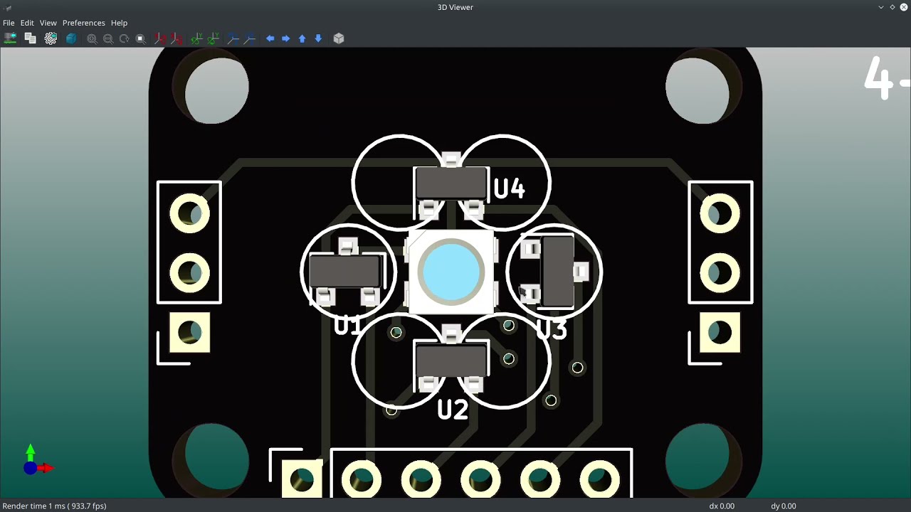
I came up with an idea for a new thing today: An analog hall effect rotary encoder with a built-in LED and 4-way hat switch function. So instead of just a single pushbutton (like an EC11) this design should give you four different buttons to press. Maybe even 8! Maybe even a full-blown joystick navigation function! I mean, we shall see. I ...
Now that I've made a slider thumbstick mechanism to go with it I'm going to change that layout a bit... The top right hall effect sensors are going to be moved further out.
It takes up about 30mm of space which is 10mm more than the compact resistive slider thumbsticks that are on the market but it has an RGB LED, is contactless, and also works as a rotary encoder! So with the right hardware configuration it could be quite a powerful input device! 👍
If you just want it to be a rotary encoder it should only take up ~13mm of space. Though, without the LED I can probably make it smaller: I had an earlier prototype that only took up about 9mm 👍
Then again, if I switched to smaller magnets I bet I could get it down to 5-7mm! 😄
elder peak
If you were to present this at a conference, clearly you'd be presenting it in the hallway track.
rustic linden
lord that joke
rustic linden
Gosh I wish I knew how to optimally place components
elder peak
I take no position on this issue.
rustic linden
it's just annoying trying to figure things out, especially when space isn't a huge issue
gaunt cedar
rustic linden
it's just annoying trying to figure things out, especially when space isn't a hu...
that's part of the fun. the journey. I just routed my first pcb and it was a bit overwhelming at first.
vapid lark
is this ok? it's a SRD-05VDC-SL-C Relaya

 opal tusk
I know some components are very specific but with a pretty heft lead time, i'm looking for an alternate to, is this a part that is safe to assume is swappable with something that has similar specs and package?
 distant raven
All I can say is good luck
Trying to source PMICs has been a certifiable pain in the butt
opal tusk
thanks 🙂 i just want to make a sweet portable scratch instrument so i can make some sweet portable hip hop
tough matrix
vapid lark
is this ok? it's a SRD-05VDC-SL-C Relaya
Looks ok.
Minor suggestion: it is common convention that GND is always pointing down, and VCC/+5V is always up
 tough matrix
Looks one of the pins of transistor Q1 is not connected?
vapid lark
that is GND
tough matrix
Oh, right, connected to copper fill
vapid lark
yea 🙂
tough matrix
Did you run DRC? Looks like the clearance between lower row of pins of ESP32 and traces is very small
BTW, what width traces do you use?
tough matrix
Wow
Usual width is 8-10 mils on signal traces, i.e 0.2-0.25 mm
1.5mm is 60 mils... I'd use it for 4A current
vapid lark
btw DRC is fine
distant raven
Large signal traces can sometimes be prohibitive and have extra inductance
I wouldn’t do bigger than 12, maybe 16mil tops
distant raven
Sorry most fabs work in mil so that’s what I use lol
Like smallest trace/spacing you’ll find is listed 3/3 which is 3mil trace 3 mil spacing lol
For reference 50mil is 0.394mm I believe is the conversation
supple pollen
That's backwards: wide traces have lower inductance
I like wide traces, where they'll fit (like here), and they're easy to manufacture.
elder peak
I like my circuit boards with a smol outline and wiiiiiiiiide traces.
carmine scarab
elder peak
I like my circuit boards with a smol outline and wiiiiiiiiide traces.
That one just takes the Cake now, don't it
distant raven
I like big traces and I can not lie
vapid lark
so im trying to follow this breadboarding i did
https://cdn.discordapp.com/attachments/622118305930674192/847228512972570644/unknown.png


but it is crying because it want 5v connected -.-
how to fix that?
distant raven
Add a 5V line to the collector of the transistor
If you turn on that transistor as is, I’m fairly sure you will have a Vce of < 0.7V

Instructables
Driving a Relay With an Arduino: Hello everyone, welcome back to my channel. This is my 4th tutorial on how to drive a RELAY (not a relay module) with an Arduino.There are hundreds of tutorial available on how to use a "relay module" but I could not find a good one that s…
 distant raven
Do you have more than one of the relay to test against?
vapid lark
i only have 1 relay
 lavish herald
When designing, EasyEDA says "There are some unfinished nets" What are nets?
gaunt cedar
lavish herald
When designing, EasyEDA says "There are some unfinished nets" What are nets?
nets are the connections. you'll have a GND net, 3.3v net etc. that error means you don't have something connected
gaunt cedar
Regarding USB D+/D-
The spec calls for 90ohm impedance on the differential trace. Does anyone have experience finding the limits to this? I'm working on a samd21 board and unless I place the usb really close to the samd pins, I'd have to run 1mm (!) traces to meet the specifications on a normal 1.6mm FR4 board.
If I've got .45mm traces on top of a ground plane, will usb be happy? traces are about 40mm long
supple pollen
It may not be happy, but it will likely still work.
You could play with co-planar waveguides, but I don't think it's necessary.
This person built an ATX form factor Arduino and stretched out the USB signals in the process, and it worked okay. https://www.sparkfun.com/news/2561
They say, "play stupid games, win stupid prizes," but the joke's on them: I love stupid prizes.
tough matrix
gaunt cedar
Regarding USB D+/D-
The spec calls for 90ohm impedance on the differential t...
I had a board where the IC (SAMD21) was about 5cm away from USB connector connected by 10 mil traces on regular 2-layer 1.6mm pcb. It worked - had no problems.
gaunt cedar
@supple pollen thanks for the article. funny read too.
gaunt cedar
tough matrix
I had a board where the IC (SAMD21) was about 5cm away from USB connector connec...
thank you! I'm accepting both of these as confirmation bias that I'll be fine and I don't need to change to a 4 layer board to meet spec. I'm just using data for loading code.
it's ok if you are aware of the requirements, decide that aesthetics are more important and to not be surprised if it goes sideways. right?
supple pollen
That's my usual approach, and I usually get away with it
tough matrix
When I designed my board, I was not aware of the requirement🤪
gaunt cedar
ignorance is bliss!
supple pollen
æsthetics matter
 tough matrix
 gaunt cedar
mixed message but I like it!
tough matrix
Not mine - but you can buy it on Tindie
gaunt cedar
someone was sneezing non stop when they routed the traces. glad it worked out
vapid lark
so im following this
https://cdn.discordapp.com/attachments/637812536158453780/847773007451258890/unknown.png
why does the ratline popup here -.- saying to connect the transistor to +5V -.-
https://cdn.discordapp.com/attachments/637812536158453780/847773141120057354/unknown.png
https://cdn.discordapp.com/attachments/637812536158453780/847773207490199582/unknown.png
what am i doing wrong here?


 heavy jasper
It looks like there's a very thin blue line running from the middle pin of Q1 down
It may be just that that net is still there and 5V even if you don't want it to be.
I'd zoom in at Q1 and see if there's an extra trace that needs deleting.
vapid lark

@heavy jasperthere we go
i moved the transistor and behind it was the 5V "pad"?
i removed it and now it is fine
heavy jasper
Also, if you relay is on the bottom of the board, I think you have your NC/NO labels reversed on the header
Unfortunately the datasheet doesn't specify whether the pinout view is from the top or the bottom, so I actually couldn't tell you which of the slightly different schematic/layout drawings and labels are correct.
tough matrix
designing a robot...
powered by: 4*1.5V=6V
obviously, I need 3.3 LDO for the MCU
but I also need in ICM-20948 IMU, which requires 1.8V, so add also 1.8V LDO
but I also need VL53l0X laser ToF idstance sensor, which needs 2.8V , so add 2.8V LDO
and looks like I might need 5V LDO for neopixels
did I miss any other common voltages? bring it on, the more the merrier
I might get a bulk discount for LDOs
unreal flax
tough matrix
I might get a bulk discount for LDOs
You might be able to consolidate a few of those, such as running your MCU at 1.8V. It also looks like the 2.8V of the ToF sensor can go up to 3.5V, so you could probably run that on 3.3V, or compromise on 3.0V or something.
elder peak
Sometimes the real dropout was the low dropout regulators you Muntzed along the way.
distant raven
tough matrix
No.
1mm is about 40 mil
Yeah, I had my head mixed up, 1mm is 39.37mil.
distant raven

When that paste goes on perfectly
Solder pasting with a stencil really is an art
gaunt cedar
did you plot the gerbers first? File -> Plot
open GerbView, then go to file -> open plot files. then you just need to find the folder you plotted all the .grb files and select them all
distant raven
 rustic linden
ooh
distant raven
Andddd I recovered two boards that didn’t initially flashhhhh
Wooo
Looking at 100% success on the two panels I’ve done today 🙂
rustic linden
ayyy
tough matrix
RP 2040 chip now available for purchase for $1!
Time to decide if I am ready to switch from SAMD21 to it...
 crude ocean
<jacknicholsen>and thats not bad!</>
tough matrix
Just when I managed to get 20 SAMD21G18 directly from Microchip and hide them in high security vault in my basement
distant raven
tough matrix
RP 2040 chip now available for purchase for $1!
Time to decide if I am ready to...
I ordered a reel of 500 😅
I ordered a few weeks ago
Should be here in July
tough matrix
For me the biggest problem with RP2040 is that they only have 4 ADC pins
distant raven
Volume pricing on the RP2040 is ridiculous
I don’t know how they are making them so cheap
crude ocean
necromancy probably
 light ermine
Maybe everyone else makes their chips that cheaply too, but add higher margins.
distant raven
You’re probably right
RPi doesn’t have much need to make a profit since they are mostly an educational foundation
crude ocean
others certainly are doing higher margins, the pi foundation has goals beyond profit
distant raven
Or make a huge profit I should say
crude ocean
they also made a new thing, so for the next little bit they just lead the tech
the industry was happy where it was :-)
not that I ever wanted to pay $25 for a mere arduino
tough matrix
Have they published the volume pricing on RP2040?
distant raven
The crazy thing here: the flash chip on the Qt Py rp2040 cost more than the RP2040 chip itself
distant raven
tough matrix
Have they published the volume pricing on RP2040?
No, I just happened to order a reel a few weeks ago directly from RPi
tough matrix
Secret early developer program?
crude ocean
it will be hard to make me stray from the pi foundation 2040 board
distant raven
Let’s just say I spent $580+ on 200 samd21… I spent $280 on 500 rp2040..
crude ocean
even with terrible availablility
light ermine
That flash chip costs more for you but not for them, probably.
distant raven
Should have them by July with current lead times
The 3000 pc reel is even cheaper per unit
I just couldn’t justify buying 3000 pieces
Lol
crude ocean
wait, 56 cents/unit?
distant raven
light ermine
That flash chip costs more for you but not for them, probably.
Flash chips at volume are still $0.60+ a piece for 16Mbit
Especially if you want qspi
distant raven
crude ocean
wait, 56 cents/unit?
$0.50 a unit and $30 for shipping
crude ocean
I ponder how many chips can be on a sanely designed board :-)
distant raven
With a good usb hub controller.. probably 4 🙂
tough matrix
But why?
distant raven
Well, for practical reasons a hub controller and 4 microcontrollers in one board would be practical from a multi system monitor stand point
Big applications in the industrial world
Obviously it doesn’t make sense for the average user
rustic linden
wait the chip is available for purchase now?
only place I can see it is sadly limited to 3
also id probably have difficulty adding one myself to a circuit, like, soldering
unreal flax
I think that's used as part of the USB power-negotiation process, to set how much current the port supplies.
 slim sandal
How can I make my own developer pc with eagle
unreal flax
slim sandal
How can I make my own developer pc with eagle
Eagle is a tool for making circuit boards, drawing out every wire between every chip. It would be a BIG job to design a full desktop computer at that level of detail.
tough matrix
rustic linden
also id probably have difficulty adding one myself to a circuit, like, soldering
Eben Upton (from Raspberry Pi foundation) wrote on twitter that they are currently talking to JLCPCB to add RP2040 to the list of components available for assembly - so you woudl be able to order a board with RP2040 on it assembled from JLCPCB
slim sandal
unreal flax
Eagle is a tool for making circuit boards, drawing out every wire between every ...
I’m thinking a little bigger than a jetson nano
rustic linden
tough matrix
Eben Upton (from Raspberry Pi foundation) wrote on twitter that they are current...
That's news I'm glad to hear! I use them for my boards, so that's good to hear
primal schooner
It's time to make the FTDI jump........for JTAG!
slim sandal
What arm processors can i run Ubuntu on
haughty wolf
slim sandal
I’m thinking a little bigger than a jetson nano
if you need to ask how to design a computer, then you are nowhere near able to make one. this happens all the time. people jump in with a incredibly ambitious and then give up and never touch electronics again. not trying to discourage you, just trying to realise your expectations
slim sandal
Oh ya I completely understand that and I know what to do I just mean to get the ram slots in to eagle and such
haughty wolf
well you're asking very broad questions for someone who knows what theyre doing
slim sandal
Ya I know
long wraith
distant raven
I ordered a reel of 500 😅
How does one order them from RPi Foundation?
ivory jasper
What do you guys think of my analog hall effect rotary encoder PCB? It's 19x19mm so it can fit in the space of a normal keyboard key (which FYI, is 19.05mm spacing). I'm going to add a pushbutton to it I think.

Back side has the pin reference

The plan for the push button is to just send a sensor pin (or maybe both) to GND. That will make it super easy to detect button presses in firmware.
(and no need for extra pins)
Was thinking about adding 4 pushbuttons (somehow--space is pretty tight) so the encoder knob could be used like a 4-way had switch or d-pad
They are, I used kicad's "Move exactly" feature to move them a precise amount away from each other. I did the same with the edge cuts lines. I went back and triple-checked everything and have absolutely no explanation as to why one of the corners doesn't have a complete GND plane connecting around it 🤷♂️
I'm tempted to move that one corner's hole by 0.001mm down/right to see if that fixes it
Hall effect rotary encoders exist but they're all proprietary, ultra expensive thingies ($200+)
Well the hall effect ones have a configurable resolution whereas the optical ones have a fixed resolution
Just like with analog hall effect switches you can configure the point at which some amount of rotation is considered a, "movement"
With a normal rotary encoder you've got two square waves that are offset slightly from each other. With an analog rotary encoder you've got two sine waves that are slightly offset from each other. With the square waves you don't have a choice: You get the next "bump" in the wave when the encoder switches the signal internally. With the sine waves you can just pick a certain amount of up/down movement in the wave and say, "I want to divide the wave into this many parts"
The only limitation is the resolution/stability of your analog signals
Unshielded analog hall effect sensors coming down a wire can have a lot of voltage wobble (think: ±80mA; I know because that's how much I get on my breadboard here haha)
If you use a nice voltage regulator and some caps you can cut that to about 1/3rd the wobble (±26mA)
However, if you go the extra mile and shield everything and use an ultra high quality (super low tolerance) LDO you can get voltage wobble down to like ±1mA and then you can reliably detect like sub-millimeter movements
It's more like: Each wire acts as an antenna and nearby digital signals (don't we all have those? hehe) can cause minor spikes in the analog signal. You can filter them out with careful choices in caps and resistors and whatnot but I find it's easier to just implement such filters in software 😄
Like, voltage wobble doesn't matter at all if the wobble is stable! If the wobble is ±50mA but it's consistently ±50mA then I know the user rotated the encoder by a little bit if a mA reading of like 2500 changes to 2501 because I'll see that the average across multiple readings went up by a little bit. The problem is that even after averaging you still get ±80mA without doing things right hehe
Well it depends on how many magnets yo used and their strength and tolerances and how well you designed your PCB, laid out your traces, put filters in place, etc. My Riskeyboard 70 uses 12 magnets in its rotary encoder but that's really unnecessary. It'd be just as good with 6 👍
Even with the mistakes I made in the PCB design (oh I made a lot of them! haha) I can still get like 50-60 "steps" per 360° rotation
I haven't done much to filter things in the code though (yet) so with some optimization I bet I could get more like 100-120
Commercial hall effect rotary encoders claim to be able to do 256 steps per 360° rotation
...but they have all-aluminum casings and expensive voltage regulators and run off 24-48V (with really great/expensive sensors too)
It lasts forever. Not theoretically forever. Literally forever. Your knob and maybe the bearings will wear out before the magnets/sensors do. Five hundred bazillion years of operation and rotations 🙂
The optical ones wear out due to UV exposure and the LEDs inside wearing out which they do regardless of whether or not someone has been turning them 🙂
I've had several optical encoders wear out/stop working in my time and it had nothing to do with electrical signals. They all either had the LEDs stop working or the little spinning disk thing broke
(spinning disk can also break due to UV exposure)
The hall effect kind can also be made waterproof and is completely immune to dust and grime 👍
...which is why the main place you see them is on things like forklifts and factory equipment
There's UV all around us all the time. Even reflected UV from nearby lights and sunlight can damage components slowly over time
Ever see an old computer that "yellowed"? That happened because of UV exposure. You can't avoid it. You can see some stuff yellowed that had been sitting in boxes for decades because some light snuck in through the cracks in the sides of the box and the plastic part was kept in a transparent bag.
The spinning disk broke in my case because it was super old (it was inside a car) and had become brittle. Just the force of me turning it really fast resulted in it detaching itself from the base. So I would spin the knob but the disk would only spin a little bit because it wasn't attached to the shaft anymore
There's another benefit to the hall effect rotary encoders: You can take the whole knob (with magnets inside) right TF off it for cleaning or swap it out for a different one 🙂
Hall effect rotary encoders can also be 100% SMD components
No through-hole soldering means cheaper PCBs 👍
Because the industries where they're used demand high quality/unbreakability (i.e. forklifts)
Lab equipment sometimes has hall effect rotary encoders too. Though that's probably more due to the fact that if you're going to pay $200,000 for a piece of lab equipment it'd better have super reliable knobs and not generate any light at all (even if invisible IR hehe)
I like them for ease of use and the adjustable resolution 👍
There's resistive ones like pots that don't stop when you turn them enough
Those wear out fast though (like all resistive pots, haha)
Yeah
I've had nothing but trouble with pots when it comes to reliability. The brushes wear down the metal coating on the inside of them over time. Especially in humid environments (I live in Florida)
Oooh, a capacitive rotary encoder sounds neat!
Pro tip: Capacitive touch pins work with analog multiplexers 👍
Well if you have the capacitive sensing over say, a 20° area of your overall encoder diameter you can just gradually add more metal wires/tracks as the encoder turns.
Stack em 👍
Well, the way the capacitive sense pins work on MCUs means that if you put a thin wire over it it'll probably pick up the rest of the wire too. So you'd need to have longer/shorter tracks pass over it
Can't just make it get wider as you go around
If you did it with a different sort of capacitive sensing that might work though
To a capsense pin your finger is representative of your entire body. You can measure this effect with a small dog's paw VS your own finger. The small dog may not even get detected! Medium size dogs work fine though. Ask me how I know this 😄
I tried it with a wet small dog too and that definitely upped the capacitance but not by enough 🤷♂️
I had this plan to make a capacitive touch... pad made out of aluminum sheet that would open the automated door opener when the dogs stepped on it with their bare paws.
It worked great for the medium-sized dog but the little one didn't have enough capacitance!
Well ideally you'd want it contactless
Contactless all the sensing!
Another thing I always wanted to try was a short-distance time-of-flight sensor: Print out a knob with ever-increasing heights of steps around the perimeter and bounce that little micro laser off of them to detect what position you're at in the rotation.
That's kinda how gesture sensors work too 🙂
 fervent lance
Nix! -nis
pearl tapir
Note that digital micrometers use capacitive sensors.
distant raven
long wraith
How does one order them from RPi Foundation?
You need a company + lots of patience and knowing who to first get in contact with. Mileage varies
 rustic pewter
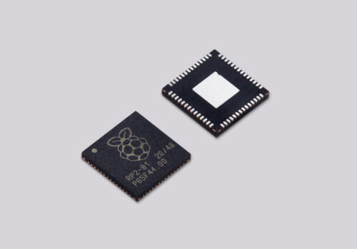
Raspberry Pi RP2040 chips are now on sale, allowing you to build your own projects and products on Raspberry Silicon
they'll let you order as little as one now
 gleaming thistle
I'm adding a Flash chip to a SAMD21E, can any 4 pins work for this?
distant raven
gleaming thistle
I'm adding a Flash chip to a SAMD21E, can any 4 pins work for this?
They have to be capable of SPI communication
Which variant are you using?
gleaming thistle
So anything with SERCOM or SERCOM-ALT?
gaunt cedar
do they also need to be on the same sercom interface?
gleaming thistle
distant raven
Which variant are you using?
the non-L one
gleaming thistle
gaunt cedar
do they also need to be on the same sercom interface?
that was going to be my follow-up question 🙂
haughty wolf
gleaming thistle
So anything with SERCOM or SERCOM-ALT?
Did you really have to capitalise sercom twice lol
gleaming thistle
haughty wolf
Did you really have to capitalise sercom twice lol
Just trying to stick with the documentation 😅
haughty wolf
i dont know why it just annoys me a bit lol
gaunt cedar
@gleaming thistle which samd21 board?
gleaming thistle
gaunt cedar
<@!385640542882627594> which samd21 board?
I'm working with the SAMD21E chip, working on a custom board
gaunt cedar

Adafruit Learning System
Get more high speed serial commports without bitbanging
the multiplex section will be helpful. your board has 4 SERCOM vs 6 just be aware
fast tundra
Also keep an eye on which of the SERCOM pads you use, since only certain ones can be clock
gleaming thistle
fast tundra
Also keep an eye on which of the SERCOM pads you use, since only certain ones ca...
that's a good point, i'd forgotten about that
fast tundra
if you tell me your exact part number I can tell you which pin combinations will work
gleaming thistle
gaunt cedar
the multiplex section will be helpful. your board has 4 SERCOM vs 6 just be awar...
right now I have everything on SERCOM0 (ALT) but i want to see if I can optimize my layout
gleaming thistle
fast tundra
if you tell me your exact part number I can tell you which pin combinations will...
Aren't all D21ExxA/B/D devices the same? (last batch: ATSAMD21E18A-AU)
gleaming thistle
fast tundra
A & B have 32 pins, C has 35.
ah, gotcha
fast tundra
I didn't think you'd be using the C but it never hurts to check
gleaming thistle
fast tundra
I didn't think you'd be using the C but it never hurts to check
had me worried for a second there 😅
distant raven
I use 17/18/19/22 for SPI and three other I can’t think of off the top of my head
gleaming thistle
distant raven
I use 17/18/19/22 for SPI and three other I can’t think of off the top of my hea...
i'm on 4/5/6/7 but i'd like those analog pins back 😄
gleaming thistle
distant raven
I use 17/18/19/22 for SPI and three other I can’t think of off the top of my hea...
22 for chip select?
gleaming thistle
gaunt cedar
do they also need to be on the same sercom interface?
it does appear based on the example that they need to be on the same SERCOM (Chip Select shouldn't matter)
 distant raven
gleaming thistle
22 for chip select?
distant raven
gleaming thistle
22 for chip select?
Yes
fast tundra
Yes, you have to use pads from the same SERCOM instance
Here's the valid configurations for SERCOM SPI for the E:
You can use any pad for DI (see CTRLA's DIPO in section 27.8.1 of the datasheet
& you can use any GPIO pin for SS, but if you do the hardware SS it'll handle pulling it low during a transaction.
If you don't the hardware SS you just need to set it low before sending / receiving and set it high when you're done.
I really need to get around to writing a nice interface for figuring out the SERCOM pins, especially for the SAMD51
gleaming thistle
@fast tundra thank you for this, I was going through it manually, I agree a script or interface would be great for this.
elder peak
I swear, Microchip ought to write you some checks for making their hardware more explained, @fast tundra. Or at least some nice pieces of schwag.
gleaming thistle
So I can mix and match between SERCOM and SERCOM-ALT as long as they're on the same channel (0/1/2/3)?
 fast tundra
Yes, as long as it's the same sercom instance it doesn't matter.
fast tundra
elder peak
I swear, Microchip ought to write you some checks for making their hardware more...
I'd settle for them sending me the MCP4728s that I need 😭😭😭
gleaming thistle
On the QT Py M0 guide it states:
A0 / D0 - Digital/analog GPIO pin 0. Can act as a true analog output with 10 bit precision, but does not have PWM.
But in the pin descriptions it has a PWM attribute:
{ PORTA, 2, PIO_ANALOG, (PIN_ATTR_DIGITAL|PIN_ATTR_ANALOG|PIN_ATTR_PWM|PIN_ATTR_TIMER), ADC_Channel0, PWM2_CH0, TCC2_CH0, EXTERNAL_INT_2 }, // A0 / D0 / DAC
Is this for maintaining backward compatibility with other devices that have this limitation on A0 or is this an error?
gleaming thistle
gleaming thistle
On the QT Py M0 guide it states:
> A0 / D0 - Digital/analog GPIO pin 0. Can act ...
I'm pretty sure the variant.cpp is at fault here, based on looking through the datasheet and other variants that use this chip.
heavy jasper
For a fixed spacing of signal-to-signal, generally yes.
For an article based on some simulations: http://iconnect007.uberflip.com/i/1014812-design007-aug2018/57?

I'm assuming here you're talking about board thickness when you say "closer to each other"
where you have signals on one side and plane on an adjacent layer.
rustic linden
When designing a breakout for a chip, it has some requirements like a pin tied to ground here, and a pin tied to VCC through a resistor there, and I'm wondering what I should add to the board? Should I just connect the chips directly up to pins or should I add some of the circuitry needed to get it up and running?
supple pollen
I like to add support circuitry as a convenience, unless it's expensive or specific to a mode I'm likely to not need. I'll also tend to leave a way to disable it, if it seems possible I would want more control, another version, or somesuch.
haughty wolf
pull up resistors for reset pins are a must for breakout boards. if youre going through the effort to buy boards you might as well add more than just a chip
unreal flax
If you didn't want to use two separate layers, you could put them both on the same layer, routing horizontally at different offsets.
I presume it's to support reversing the cable plug.
supple pollen
Could a coplanar structure work?
primal schooner
Rotate chip.
Rotate chip if 1) speeds below 10MHz. 2) Impedances that differ are calcualted and are within an acepatble Q value.
Or flip the chip on the other side
supple pollen
Could you do something like this?
 tough matrix
quick question.
I finally decided to move to KiCad 5.99 (after several years of using Eagle).
Now, I tried uploading my gerbers to JLCPCB (following instructions from https://support.jlcpcb.com/article/149-how-to-generate-gerber-and-drill-files-in-kicad)
the board previews OK on JLCPCB quote page, but when I click on "Gerber viewer", this is what I get:

and "analysis" shows

any ideas what it could be? DRC finds no errors (other than some issues with silkscreen overlaps which I told it to ignore), and KiCad 3d viewer previews th board just fine
tough matrix
pcbway online gerber viewer shows the board fine, too: https://www.pcbway.com/project/OnlineGerberViewer.html
so it is probably a bug in jlcpcb viewer... but yet, anyone knows if there is a way around this?
tough matrix
Sorry - what do you mean by that? If you upload the Gerber file I posted before to JLCPCB, it shows correctly in their Gerber viewer?
Is it JLCPCB?
Did you try clicking on "Gerber viewer" link underneath?
heavy jasper
@thick willow This is pretty much just the way for type-C, nearly everyone I know just routes the crossover and it works, or routes on an inner layer to loop around and that also works. The stub length ends up being not that huge of a deal for USB2. IF you really really care, there are various input protection/mux chips that accept both ports and the CC pins to detect orientation and mux the appropriate lines. More so you generally use those chips if you need their other features (PD support, or muxing of the high-speed signals as well for alternate modes)
rustic linden
What is the width of a DIP chip?
heavy jasper
0.1" pitch, with varying width depending on the chip; most commonly 0.3"
rustic linden
what's the minimum size I can make a hole/pad for a set of headers?
rustic linden
yeah, but if i make tiny holes, the headers I have probably won't fit
silk lark
well, then it depends on what headers you have
I usually use 0.9mm holes and 0.4mm ring around them
for the standard goldpin headers
at 2.54mm spacing this leaves enough room between them for an additional trace
tough matrix
The usual 0.1" spacing male headers are square with side 25mil=0.64mm, so diagonal is 0.9mm
But of course there are many different kinds of less usual headers
distant raven
Yeah
tough matrix
@thick willow for me the problem was exactly with the gerber viewer. the quote page which you get after uploading gerbers looked OK, but gerber viewer had difficulties. Can't explain why.
But I had fixed the issue by making minor modifications to the design, so now it works OK.
supple pollen
The "(null)" errors imply a problem with file upload or naming.
 fierce apex
so is kicad the program to use for board designing ? if given a choice
silk lark
YMMV
unreal flax
Yep, if you're starting from zero, that's a good one to pick. A lot of Adafruit designs are done in Eagle CAD as well, for instance.
fierce apex
well eagle has a board size limit?
silk lark
Eagle is subscription now, no?
unreal flax
Yes, and yes. Kicad I would say is the best free alternative to paid CAD apps. Personally I pay for Eagle, but that's just because I learned it a long time ago, so it's worth it to my productivity versus switching tools.
vapid grove
That feeling when tsot-48 atmega32u4 footprintalmost fits into arduino pro micro footprint so you need to pay almost twice the price for qfn version
fierce apex
i did make a tiny adaptor board so a FTD232 SMD can fit on a DIP chip style for a breadboard , but the 100 + pin chips are a nightmare
fierce apex
old toaster oven?
silk lark
that's good for reflowing them initially, but not for reworking
fierce apex
mmm ok , is that using that paste stuff ? its lower than normal temp solder
i have been avoiding SMD -- but looking at if fondly from a distance
silk lark
I'm using both hot air gun and hot plate with regular solder -- I tin the pads first with soldering iron, and then heat them and place the components
there are many ways of doing this
silk lark
I'm too stingy for stencils
distant raven
And then adjust position and take care of bridges if they happen
tough matrix
distant raven
And I use a hot plate to reflow
Same here
tough matrix
silk lark
I'm too stingy for stencils
Stencils from JLCPCB are $7, so it is much cheaper than it used to be
silk lark
considering the PCB is $2...
tough matrix
:)
silk lark
and then you need a new one for each new revision
distant raven
Well, no planned revisions for a while on those panels
Only downside is I won’t be able to get the samd21 I use on it for a while
Looks like September if I order now
rustic linden
Personally use EasyEDA, it's the one I'm the most familiar with, I also use JLCPCB, there's only 2 services I can use (JLCPCB and PCBWay) and I find JLCPCB much easier and better to use (but ymmv)
tough matrix
distant raven
Only downside is I won’t be able to get the samd21 I use on it for a while
didn't you order like a full reel of SAMD21?
which one is it that you are using on these boards?
distant raven
I ordered 200 back in April. I have 20 left
tough matrix
wow, you do make a lot of boards
Microchip expects new batch of ATSAMD21G18 to arrive in late August

(this is for TQFP)
distant raven
I’m looking at getting 50-100 more. But I need more LDO first
rustic linden
I'm very curious to get my hands on the RP2040, I luckily have no designs that need a chip that's been out of stock
distant raven
I think it is probably safe to say that most accessory boards will use 150-200mA
tough matrix
distant raven
I’m looking at getting 50-100 more. But I need more LDO first
Good luck

(this is for AP2112K-1.8)
distant raven
I found some from Richtek
$0.37 a piece though but exact drop in without any changes to capacitors
1uF supply side, 0.47uF output side
tough matrix
replacement for AP2112?
distant raven
Nah, I use the TLV75533
It’s a low quiescent 3.3V 500mA LDO
Like <30uA without load
The Richtek one is 39uA quiescent
But it’s a common LDO in automotive applications as are most Texas Instruments LDO and power products
So if you could imagine there are none of these LDO available anywhere. I’ve got about 140 left
tough matrix
"low-IQ" chip :)))
that's what it says on product page in Mouser
Actually this one is in stock (ony 300mA): https://www.mouser.com/ProductDetail/Texas-Instruments/TLV73333PQDBVRQ1?qs=9r4v7xj2LnnYANXVL3PB4Q%3D%3D

Mouser Electronics
distant raven
I may have to keep that one in mind for some of my breakout boards
 untold seal
What is the cheapest PCB design maker for small quantities?
I mean to buy a design that I made from a PCB manufacturer...
distant raven
Depends what on the size and where you live
Generally JLCPCB is good for larger boards which are greater than a few square inches
Or PCBWay
I use OSH Park because I’m in the US and most of my boards are small. I can prototype for less than $5 and get free shipping with a similar turn as JLCPCB when considering shipping
silk lark
I use elecrow because different colors and thicknesses are the same price
and I'm sick of 0.6mm green
supple pollen
I normally use PCBGogo, OSH Park, or JLCPCB. Another friend of mine is fond of Seeedstudio (10 boards for $4.90 + shipping). Pictured is a board I designed for a local hackerspace that I had made by PCBGoGo.
 silk lark
oh, and for special needs, when I need multiple projects on one board, I use DirtyPCBs
elder peak
Oh, yeah, I have a giant blob of PCB bits almost ready to DirtyPCBs.
tough matrix
Have any of you used stickvise: https://www.adafruit.com/product/3197 ?
is it worth the money?

Are you still looking for that perfect PCB holder? The low profile PCB Stickvise might be just the thing you need!In performing the simple task of holding a PCB near table ...
elder peak
I LOVE MY STICKVISE.
It's the only grippy-ish thingie on my electronics bench that I don't actively loathe.
untold seal
distant raven
Depends what on the size and where you live
All of these companies put the components in the PCB? All ready?
untold seal
supple pollen
I normally use PCBGogo, OSH Park, or JLCPCB. Another friend of mine is fond of ...
These have PCBA service?
distant raven
JLCPCB does
unreal flax
JLCPCB does, pretty cheap, but they do it by having a fixed catalog of available parts they will assemble, so you kind of have to design your board for that.
distant raven
PCBWay
untold seal
I think I desined yeara ago on EasyEDA
And they had a direct connection to PCBWay so you could buy it directly.
But I really don't remember if it was PCBWay...
I think I heard years ago that Adafruit produces their own products.
I tought it was really cool.
distant raven
EasyEDA connects directly to JLCPCB
ivory jasper
So if I put an electromagnetic coil underneath this what is the likelihood that it'll fry the ws28128b-b LED or the (SOT-23) hall effect sensor (or the tiny caps) when I use it to provide haptic feedback on a keypress? 😄

My guess: It'll disrupt the signal going to the LED so it'll flicker for a moment while the coil is active. The signal coming off the hall effect sensor will basically go nuts as well. The real question is: Will this permanently damage them? I honestly don't know!
Another question: Would it increase the voltage on the signal trace coming off the hall effect sensor that I'd need to have some protection at the IC reading that signal? Assume it's 5V
pearl tapir
It's not clear what the purpose of the coil is. Does the key have a magnet that you are trying to vibrate?
LEDs are current operated and, assuming a reasonable limiting resistor, it is doubtful that you could see the tiny induced voltage. Also note that your eyes are logarithmic in their perceived intensity.
It's not clear how a strong magnetic field would cause the Hall effect sensor output to exceed it's supply voltage but you can always add a clamp diode and not populate it if it isn't required.
 twilit aurora
well first of all: How big is the size of the coil (in Henry)?
 worldly schooner
So I have access to a surplus of 800x480 capacitive touch screens, and I'm trying to design a custom dev board for tinkering with it. My idea is to stick some headers on a carrier board for a Pi Pico and CircuitPython it, but I'm wondering if I can source a driver chip like an RA8875 to free up some GPIO for other tinkering. I looked around, but all the chips for this seem to be reserved for large escrow orders directly from HK/TW, as they seem to be nonexistant outside of dedicated prototype boards like Adafruit or Sparkfun. Does anyone have any ideas?
silk lark
there is a global chip shortage right now, it might get better later
 scarlet chasm
Anybody know of an Eagle .lbr that has a QT Py footprint? I see the XAIO footprint from Seeed, but it doesn't have the header holes (and there's no cutout for the back for the extra memory or the RP2040 components). Hoping to avoid duplicating some work! 🙂
distant raven
I have a footprint that I could probably modify for cutout
scarlet chasm
Even just the one w/headers would do for now (my current project won't use the castellated pads & will have headers so the cutout's not critical
In the long-run I'd like one that had "all of the above"
distant raven
I think mine is castellated pass with headers
distant raven
I’m not 100% sure. I may have at one point but it was a while ago
I try to share things but sometimes forget
scarlet chasm
Well, point me at a link if you find one - thanks!
ivory jasper
pearl tapir
It's not clear what the purpose of the coil is. Does the key have a magnet that...
Yeah, I'm trying to add a bit of force feedback indicating when the switch actuates (because it's an analog key switch the end user can choose the point of actuation).
supple pollen
I doubt the magnetic field would induce enough voltage/current to interfere with the operation of the LED


