#help-with-hw-design
1 messages · Page 46 of 1
 elder peak
But, yeah, I get DEEPLY ANNOYED when they aren't sufficently specific with connectors.
 cosmic condor
I'm trying to make something similar to a pcb ruler, but with a twist. It's for a project where I'm trying to make it easier for people to draw mayan glyphs, using an old and cool system called the "leroy lettering" (which is just a pantograph).
https://www.youtube.com/watch?v=5t1YLxb2hbY

Demonstrating a Leroy Lettering Set in action. See my full blog post about it here: http://www.benzilla.com/?p=5433
(Fran Lab has a longer, nicer video if you want to geek out with old tools)
cosmic condor
How would one draw a relief ilke that on kicad, a can a manufacturer like oshpark make something like that?
 royal cypress
Haha it's not! I started paying attention, and if this insanity isn't a good indication that it's adhered to, I don't know what is.

 tough matrix
@cosmic condor I haven't seen pcb manufacturers that can do reliefs - typically the only milling they do is for the full thickness of the material
cosmic condor
@tough matrix Thanks for the input.
 median stirrup
This PCB-potentiometer (assuming that's what it is) is wild! but what does the board do? https://www.bunniestudios.com/blog/?p=6062

 silk lark
pretty colors
median stirrup
the internet tells me that due to the low resistance of copper, a PCB potentiometer would be useless
silk lark
it might be a variable inductor?
median stirrup
my assumption was those two fat green traces were feeding into either end of it and the wiper was tapping the semicircular trace in the middle
I suppose you could also build a PCB capacitor depending what's on the other side of the PCB, or in an inner layer
silk lark
variable capacitors usually have two (or more) plates that move in relation to each other
median stirrup
yeah that makes less sense than I thought
a half turn doesn't seem like much of an inductor either
silk lark
but note that there is no connection from the "wiper" to anything
median stirrup
I was imagining that rivet went through a trace on the bottom side, and then the trace coming out from under the nut near L3 was connected to it as well. but I can't say for sure it is
silk lark
but there is no wire going along the transparent part of acrylic
or is the wiper made of pcb and not transparent?
median stirrup
it looks like PCB with green silk to me
silk lark
oh, right, it's pcb
another possibility is that that copper trace is actually covered with some material with more resistance
usually carbon is used, but that would be black
oh, I know!
the actual thing being switched in on the other side, the wiper is only for connection to the center
a multimeter with a rotary switch
there is probably a second wiper on the other side
median stirrup
these I'm familiar with
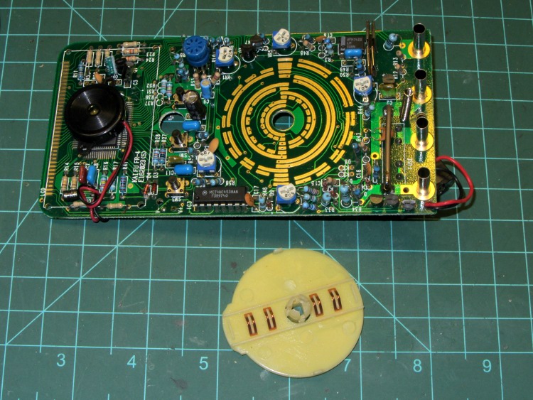
but as this looks like it's unbroken I'm not sure how it could have the same kind of function
2n5901 is RF transistor
silk lark
the traces on the other side are broken, this one is just for connecting the center
median stirrup
oh I see what you might be saying now
silk lark
they used a wiper for a better and more reliable connection, I guess?
 harsh pendant
deos this SD card circuit seem right? Just wanna check before i get this board manufactured

 unreal flax
harsh pendant
unreal flax
harsh pendant
Seems sane to me.
 spark sun
designing some (more) PCB badges, anyone have any favorite part #'s for side-mounted SMD LEDs, preferably available from LCSC? I've been using the TOGIALED ones which seem OK but curious if there are any preferred.
sneak preview of the board art 😄


 carmine scarab
Priority unpacking!
 distant raven
Exactly!
carmine scarab
Welcome home I suppose!

 misty escarp
looks great!
 ember laurel
yeah that's a nice place
good luck finding those 0402 resistors once they hit the carpet though

 tough matrix
looking at the brd image, it seems that in many places there is very little clearance between traces - for example, the trace going from resistor R9. But it may be artifact of low-resolution image. Did you run DRC?
 fervent lance
ideally drc errors should not open
tough matrix
also: I don't see sda/scl pullups - are they included on bmp388 breakout?
carmine scarab
distant raven
Office vibes
Yikes! Carpet though.. Zzzzzap! 
distant raven
Yeahhhh
carmine scarab
5:48 and you're up? Someone's still on Eastern time!
 fathom lotus
anyone else notice kicad 5.1.9 be a laggy mess compared to older versions? it feels like it's running like crap even though my system hasn't changed at all. running arch linux on pretty beefy hardware
looking in htop it's not even using many resources but it still feels really bad to use
carmine scarab
Meh, what's 3600 seconds between time zones!
fathom lotus
would appreciate if someone could check if this would work 🙂 rawvcc is 5v, 3.3v is obviously 3.3v, oled reset is 3.3v, b5 is 5v.
the oled (on oledreset) is reset when oledreset is pulled low by pin b5, but since the oled is 3.3v logic, the 5v from the controller would probably fry it. put in this bss138 level converter and want to make sure it's wired up correctly so that when b5 is high (5v out) oledreset is also high but with 3.3v out
also, should i put the same circuit (and also some pullup resistors) on the i2c lines?
 harsh pendant
tough matrix
looking at the brd image, it seems that in many places there is very little clea...
harsh pendant
tough matrix
looking at the brd image, it seems that in many places there is very little clea...
yes. ran drc no errors. scl/sda pullups included
ember laurel
phew, just got another order of my board out
JLCPCB with SMT assembly
I keep having troubles with their PnP
lots of manual coordinate and rotation tweaking required
264 components on the board, 58 unique
 haughty wolf
what are your boards for?
ember laurel
dental motor control system
haughty wolf
of course lmao
ember laurel
JLC doesn't do edge plating though
I really wanted edge plating for this prototype :/
 dark fox
I finished this a few weeks ago... but I wanted to post it because I literally knew nothing, zilch, nada about making a PCB and with some YouTube time, Fusion 360, OshPark and Seattle Makers (to do the assembly), I was able to make a PCB with some connectors on it for a work project.
Anyway.... point of that is just to say. If you put in the time... anyone can make a PCB project. Obviously my project was very simple, but still, if "I" can do it.. believe me YOU can do it !
 distant raven
Beautifully done @dark fox
misty escarp
Looks great
carmine scarab
I love those copper(?) traces on the black. Very nice @dark fox !
 round fog
@dark fox you're at Seattle Makers? That's rad, is Jeremy still running that place?
Nice job on your PCB
dark fox
round fog
<@!624005998696333331> you're at Seattle Makers? That's rad, is Jeremy still run...
Yes he is still there. I'm relatively new around the place.
round fog
It's a nice little shop. If you see Jeremy you can tell him Lucian says hi.
Are they still in that old hat factory building?
dark fox
carmine scarab
I love those copper(?) traces on the black. Very nice <@!624005998696333331> !
OshPark afterdark looks pretty on most everything
dark fox
round fog
Are they still in that old hat factory building?
Hmm... I call it the School of Visual Concepts building \ art school building. Might have been a hat shop, but I don't know that history.
Seattle Makers
round fog
Yeah, looks like the same one. I basically lived there for about 6 months or so after the company I was in went belly up haha
I thought that Amazon was going to demolish that whole block and make them move but I guess they never got around to it
dark fox
.. yet 😉
misty escarp
The year is 2060, Seattle is all Amazon properties, drones occupy all apartments and the humans shelter in the remains of coffee shops in search of wifi or crackers.
elder peak

Okay, the 0805 415nm UV LED (https://www.digikey.com/en/products/detail/sunled/XZVS54S-9F/9920871) has an exceptionally odd package. No pads on the side, pads on the bottom. Still managed to get it soldered.
We're sorry. This is not a functioning page on our site.
tough matrix
A really naive question:
why are we using load switches? what is the advantage over just using a mosfet?
elder peak
Wirehead's first rule of power-electronics: If you want to do something with power, somebody's probably packaged it as a load switch or a MOSFET controller.
The biggie is that if you want to make a high-side switch that's run off of a logic level, you are goinna need an n-channel MOSFET to drive the p-channel MOSFET to the right voltage, whereas a load switch can contain both bits.
The one that @distant raven has a breakout for will do an orderly charge/discharge with externally set values.
I've got a AP22815 soldered to a breakout to screw with it because it looks like it provides a really nice way to prevent power from flowing backwards over the USB line without the drawbacks from using a schotky diode.
distant raven
Tends to be pricier to build it with individual components too
Whereas a load switch costs like $0.30 for 10W
elder peak
I don't think @tough matrix asked a naive question, just... a loaded question.
Also, at least some of the time, the load switches come with more through anti-zap measures than the component parts.
 heavy jasper
To expand a bit on “anti-zap measures,” load switches (nice ones, at least) tend to have things like built-in thermal protection, current limiting, and the like that reduces the likelihood of electrical overstress and device failure. In other cases, they will also more commonly use N-FETs which have better conduction/resistance properties but need a positive Vgs for high-side switching, so a load switch will package the switched-capacitor gate drive circuitry to enable that positive Vgs.
Some will even include internal scaled-down current mirroring FETs off the large FET, which means you can attach a resistor and read it as output current. These readings tend to have pretty wide error bars due to process variation and temperature, but are a lot cheaper and smaller (if you’re already buying the load switch) than adding an external shunt/amplifier circuit.
fervent lance
@elder peak Nice chip! AP22815 neat.
 frozen lichen
Has anyone here had experience with making their own esp32 boards. i'm having some communication issues i could use a hand with troubleshooting?
distant raven
@frozen lichen what kind of ESP32?
frozen lichen
esp32-wroom-32u
distant raven
Using the mini module?
frozen lichen
distant raven
<@289513679823699969> what kind of ESP32?
on my uart its sending data to the esp32 but the esp32 isnt responding. yes using the mini module
distant raven
Okay
frozen lichen
So Channel 1 is the TX snd Channel 2 is the RX

i've built up 2 boards and both are the exact same
 light ermine
That doesn't look like a valid tx signal?
distant raven
I agree
frozen lichen
ill show you my healthy dev kit and what that shows
oh i dont have a photo of that :/
any ideas? im using a ft231x usb-serial interface. i can show you my schematic if you want?
That is my healthy dev kit and what that’s doing but like you say they look completely different

this is the schematic
 frozen lichen
ahh bugger okay, time to lift some pins 😅
frozen lichen
@distant raven its still the exact same :/ only reversed
distant raven
Are you getting 3.3V on the ESP32 power pin?
frozen lichen
ayyy sorry i dont know what i was doing wrong but im getting data through on putty now!
thanks 🙂 N
now im getting data out with putty but i can access it with esptool
got it
elder peak

We were talking about the AP22815 and I did verify experimentally that it will block reverse voltages over the USB port and stuff
distant raven
That’s pretty cool
 unkempt remnant
Quite a while back, I was trying to figure out what the reflow profile ought to be for an aluminum PCB, since the info that comes with the solder paste assumes you're working with FR-4. I contacted QuikChip, and their response was "you want to lengthen every phase in the reflow profile just enough for the board to hit the target temperature for that phase, and you don't have to do anything special to measure the board temperature (an infrared thermometer or temp probe is fine)"
Thought you guys might find that useful! It's definitely a better method than "reflow some resistors and squint at the pads to see if they look like they got correctly soldered".
@elder peak dangit, why is the AP22815 out of stock on digikey. I might have to resort to (gasp) mouser
elder peak
There's a buncha SOT23-5 parts from Diodes Inc that have the same pinout as the AP22815 but with slightly less current handling
fervent lance
I saw this the other day but I forgot what I learned about it. I think I said 'nice chip' after reading the datasheet (briefly). Load switching?
(let's have a breakout board on that ;)
Too many years of using relays for that. ;)
elder peak
It's a load switch with reverse voltage protection, plus over/under voltage and short circuit protection.
Also, cheap and small and handles 3A.
fervent lance
3A pretty nice!
elder peak
And it's got a FLG line that will blink if you managed to short circuit or overheat it or something like that.
So, as a breakout, kinda nice. As part of a Feather or something like that, even better.
fervent lance
I just use schottky's dumbly. Had a situation arise where the Raspberry Pi was ordinarily powering something, but that something had a secondary port for special occasions (uploading firmware by a second path using ST-LINK rather than the usual path).
I needed to prevent the secondary serial port from trying to power the Raspberry Pi (a hefty load).
fervent lance
I got some really good ones from DigiKey. Accidentally overspec'd. ;)
1N5822G I think
They worked so I considered it a done deal.
 ivory jasper
Has anyone got a good power select schematic I can copy? I have two 5V inputs into this board with a built-in USB hub. I need to have it switch to the external 5V power when that gets plugged. I didn't think this would be this hard! haha
I had one that worked with three MOSFETs but it had a problem where if you plugged external 5V in then unplugged it the current from the other side (PC's USB VBUS line) would leak back through. Meaning I could detect the connection of external power once but then never again (because now that pin on my MCU would always show a 5V connection).
I don't mind using an MCU pin to detect external power and signal based off that but I thought something like this would've been solved by now
I expect to draw a max of 3A @5V (4.5V is OK but 4.4V is pushing it haha). Zero voltage drop is preferable though
fervent lance
@ivory jasper Every Adafruit target board has some form of two sources of power, detected and one is overridden by the other.
Metro M4 Express, Schematic:
https://learn.adafruit.com/assets/53093
ivory jasper
@fervent lance Excellent! Thanks
@fervent lance What's this disconnected resistor thing?
 fervent lance
USB_HOSTEN connects to PB07 of ATSAMD51J19A.
ivory jasper
R1G$3 is just sitting there... Connected to nothing
fervent lance
So it's an output from the MCU.
ivory jasper
...but where? There's no label or anything
ivory jasper
Ahh
fervent lance
VIN seems sourced at cell A6.
So when 2.1mm DC supply is active, so is VIN.
I don't know what the unconnected resistor does or where it is.
They don't usually make mistakes .. the schematics are very good.
Pin 4 of 74LVC1G125 is an output.
Pin 2 is the corresponding input, and Pin 1 is /OE ('not output enable - active LOW').
So you control it by Pin 2 which is tied to Pin 1.
Again this supports the idea that the MCU is controlling this level-shifter.
This is all in some effort to turn TR1 on or off. ;)
(This is more complicated than most of Adafruit's stuff)
(Just happened to accidentally pick the complex one!)
Here's Feather M4 Express, Schematic:
https://learn.adafruit.com/assets/57242
That one is more typical: VBAT vs VBUS.
They both feed a singleton AP2112-3.3 voltage regulator (3.3 VDC out).
Note the floating resistor tied to nothing on the upper left corner, too)
VBUS in this schematic is sourced only at the USB micro-B connector.
VBAT is a JST connection to a LiPo battery.
Obviously, in Cell A1 the aim is to have VBUS override VBAT to save on battery life, and (also) to charge the battery (Cell A6 of the schematic).
ivory jasper
@fervent lance Just tried to replicate this in Kicad... Does this look right?
 fervent lance
VBUS forward-biases D4 (MBR120, a schottky diode?) whereas VBAT reverse-biases D4 (Thus D4 won't conduct and backfeed the USB port from the LiPo battery).
ivory jasper
So the point is just to disable TR1 when VIN is plugged in? What voltage does VIN need to be for this to work?
Assuming VIN is 5V that means the voltage divider is putting out 2.5V at TR1. I assume IC3 is boosting that somehow?
fervent lance
VIN is supplied by 2.1 mm DC barrel jack.
ivory jasper
In my schematic I've got VIN as a 5V-only external source. Meant to power the USB hub (and RGB LEDs)
(for reference, it's a keyboard with a built-in USB hub)
fervent lance
I'm leaning towards saying that when 2.1 mm DC barrel jack has (proper) voltage the VBUS of the USB connector no longer supplies power to anything we care about.
ivory jasper
Yeah that's the plan
fervent lance
I'm talking about the existing work Adafruit did. ;)
If you make any substitutions it's your job to see that 'they work'. ;)
ivory jasper
Well I don't plan any substitutions except maybe that MOSFET (if it's not in JLCPCB's part catalog)
fervent lance
USB_HOSTEN would be if you want to power a mouse or keyboard, I'd suppose.
In that instance you very much do wish to back-power the existing USB micro-B connector. ;)
ivory jasper
So USB_HOSTEN comes from the MCU... If it's HIGH it enables the external supply?
fervent lance
And ATSAMD51J19A decides if you get this privilege or not.
Or low. I didn't look.
(Haven't been thinking about it until 3 seconds ago)
ivory jasper
Right, it could be either... Doesn't matter though. The point is the MCU makes the decision as to which power supply gets selected
fervent lance
Yes, it needs to be able to power the USB port where it's appropriate to do so.
You could (of course) tie the MCU input to the level shifter, to one of the rails, for permanent duty.
ivory jasper
Oh so this just switches VIN -> USB VBUS?
fervent lance
(disconnecting it from the MCU before doing so)
ivory jasper
...so you can use USB OTG I assume?
fervent lance
answering questions in your parlance is 20x harder than explaining what Adafruit already did. ;)
ivory jasper
Sorry 😦
fervent lance
Nothing to be sorry about .. I always think this is symmetrical but it really isn't.
If I say yes and you get blue smoke ..
I think this is to provide for USB OTG or a mouse/keyboard or both. Don't know.
Probably just so you can use Metro M4 Express as a substitute for a PC's mouse or keyboard.
Note that VIN is only sensed locally - it does not supply anything in Cell A3.
It sits at the top of a voltage divider, only.
It's a sensing circuit.
NCP1117ST50TG3 sources DC +5 from VIN.
This is the same +5V at the leg of TR1.
ivory jasper
After looking at several Feather board schematics I think this one suits my application more

...except I'd replace VBUS with VIN and VBAT would be VBUS (from the PC)
That way VIN would get prioritized over VBUS
fervent lance
So I'd guess (only a guess) that TR1 prevents this source of +5 from back-feeding VBUS at the USB micro-B connector.
ivory jasper
That's from the Feather STM32F405
fervent lance
Yeah Adafruit did enough variants that if you comb through them you're likely to find a match to your application.
ivory jasper
Only problem I have with that STM32F405 schematic is D4 will need to be able to handle a lot of current. I suppose I could just make multiple connections off the VIN line
fervent lance
D4 bypasses the transistor there.
ivory jasper
You mean the MOSFET?
fervent lance
So the 'sense line' is VBUS on the GATE of the FET.
ivory jasper
Yay! I got it right then!
fervent lance
;)
I would not commit to permanent difficult to construct stuff until you've worked it out on the bench for sure. ;)
ivory jasper
My STM32F401 MCU has 5V tolerant pins (well, most of them are) so I can sense external power just by running it directly to a pin on the MCU (with a resistor of course--just to be safe)
fervent lance
;)
ivory jasper
Nah, I like to live dangerously!
ivory jasper
I'm designing revision 2 of the Riskeyboard 70 PCB. It's this thing: https://gfycat.com/alienatedflatcanvasback
 fervent lance
Hehe. Nice.
ivory jasper
It'll have an entirely different USB hub chip this time around and a whole lot of pins have been remapped
Lots more dedicated connectors too
The previous version just had all the extra pins broken out at the back but this time I've got some that are meant for things like that display. So right now that display is plugged into several different GPIOs at the back of the keyboard that are kinda randomly placed. In rev 2 I'll have those all together in a set with their own 5V and GND too
Another lesson learned: Rev 2 is going to have WAY more mounting holes! haha
fervent lance
So what kind of display is that?
ivory jasper
Mounting holes don't hurt anything (except cutting up the ground plane I guess). So the more the merrier as far as I'm concerned. It'll give me more flexibility with the case design
fervent lance
I would be like a jazz player with dark sunglasses on, just to sit at that thing
ivory jasper
That is two 4-matrix MAX7219 displays soldered together in the middle
I have an 8-matrix one now though that I'll be replacing it with (same thing, just a solid PCB; so it's easier to keep straight)
fervent lance
No I mean what's the technology and geometry? Seems fairly dense in pixel-equivalents.
ivory jasper
8, 8x8 red LED matrices powered by 8 MAX7219 chips
Does that answer your question?
They make blue, green, and white versions too!
Though the white ones are like 3x the price! So forget that! haha
fervent lance
So it's 16 pixels high?
ivory jasper
8 pixels high
fervent lance
The video is deceptive - makes it look more fine resolution.
ivory jasper
Using this font: https://crates.io/crates/font8x8
fervent lance
I use a Lumex 96x8 RGB matrix with TTL Serial decoding (Hayes AT command set).
ivory jasper
This gif might help you understand the dimensions better as this was before I got the scrolling text code working 😄 https://gfycat.com/ethicalaggressivebrant
76543210: Each number is on its own matrix/display
Rev 2 of the PCB is also going to have a spot where the end user can solder a TSOP38238 to the board if they want infrared control: https://gfycat.com/marriedtediousaquaticleech

I also added a bunch of little solderable/cuttable solder jumpers so end users can re-configure how the LEDs work. For example, you can disconnect them and re-route them to an external connector. Or have the external connector start at the beginning or end of the LED chain.
I also still need to figure out a whole bunch of stuff like, "Where's the best place to put the buzzer?" hehe
fervent lance
Thanks so that's 7x7 glyphs on an 8x8 matrix.
ivory jasper
Technically it's an 8x8 font but normal characters only take up 7
It's the unicode stuff that uses the lower part (I think)
Because of how Rust does static compilation it'll only include the characters that you've got inside any &str in your code. So that means I can support loads of unicode characters without having to worry about how much space that'll take up on the MCU's flash 👍
fervent lance
96x8 works out to 32x3 or 16x6 or 8x12 columns.
ivory jasper
Well it's 8 displays so it's 64x8 🙂
fervent lance
So basically 12 columns with a square aspect ratio.
ivory jasper
I can tack on many more displays if I want. I could make it 64x64! A massive display hanging off the back of the keeb!
fervent lance
64 columns of LEDs is 64x1 or 32x2 or 16x4 or 8x8 - 8 columns square aspect ratio.
ivory jasper
Though my code right now only assumes it's one character row. That's easy enough to fix though 👍
This is the displays: https://smile.amazon.com/gp/product/B07X95H9DT
fervent lance
I'm presently thinking about adapting 80 columns of text to SRAM geometry.
(which wants say, 64 bytes per row rather than 80 bytes).
fervent lance
I want it to be efficient packing but I want the 80 column human factor.
ivory jasper
Oh I get it!
fervent lance
No it's endemic powers of two.
ivory jasper
Read the vt100 manual! That's exactly how it works!
fervent lance
16 bytes is the typical width of a DUMP.
I want it so that a hex dump corresponds more closely.
ivory jasper
Linux terminals "emulate" vt100 but a vt100 terminal was a physical thing and it had a very detailed manual talking about how you're supposed to store the characters in memory and whatnot.
fervent lance
Thinking about a 3-cycle: 32, 64, 96 like that but stop at 80.
ivory jasper
I believe they were 7-byte characters though
ivory jasper
Why get so low-level? There's got to be an existing abstraction/lib you can use
fervent lance
If you were to create a text editor from scratch, using powers of two as the geometry, where do you pick your column width for human factors? How did they get to 80 columns, not 64 columns?
Forth is entirely low level.
ivory jasper
Aha! I know the answer to this one!
fervent lance
That's the point of it.
ivory jasper
Typewriters
Standard letter with standard typewriter characters gave you 80 columns to work with
fervent lance
Right but on a computer, you have SRAM geometry to consider - wasting valuable SRAM by ignoring the 'extra columns' that don't fit into a power-of-two schema.
ivory jasper
That's how I learned to type! Using IBM typewriters (not the ball kind either--the old school lever-the-damned-character-on-to-the-page type)
fervent lance
64 columns would be inhibiting; 96 is too wide. ;)
ivory jasper
Well, in the vt100 manual I believe the extra bits were used for storing metadata about the characters
fervent lance
I think we're now well outside the scope of #help-with-hw-design (sorry to the channel).
ivory jasper
ABC<special bit indicating bold text>DEF<bit indicating the end of special font> etc etc
Yeah probably
fervent lance
#general-chat or #general-tech better for current thread. ;)
ivory jasper
So I'm redesigning this PCB and I have boatloads of room... Anything cool I could do with all that space? 😄
I've got the IR receiver, a buzzer, LED reconfigurability, an LED output port (multiple, actually), and a few other nice things but I'm like the Little Mermaid here. I want mooooooooore!
fervent lance
I would put in a monitor MCU.
ivory jasper
Well, an extra MCU is a ton of work. I'm talking about... "add place where the end user can use some of those external GPIOs for <insert cool/useful IC>"
fervent lance
You can get one of them castellated pads breakouts and just solder it flat.
ivory jasper
Oh, you mean add a spot to solder in an external MCU board. Interesting
fervent lance
Yeah would be an add-on you don't have to populate if you don't need it.
ivory jasper
What would you use such a thing for on your keyboard PCB?
fervent lance
Run lots of traces to/from it to all your cool stuff elsewhere on the board.
I would do it and then find the uses.
ivory jasper
Hahaha! Sounds like something I'd do hahahaha
fervent lance
Like an analog synthesiser that has hidden MIDI inside to control all the front panel stuff or at least 'read the patch'.
ivory jasper
I'll add a place for that new ESP32 board that replaces the ESP8266. That way the end user could get their keyboard on wifi!
Log data via MQTT
fervent lance
Yeah an SD card reader slot.
ivory jasper
Rather, invoke macros on the keyboard that do IoT stuff
fervent lance
You can have a lot of terminations that you don't populate.
That way it's more universal; when you think of an application that needs an SD card you're not hanging stuff outside the cabinet to do it.
ivory jasper
Yeah that's why I was asking for ideas. Now you have me thinking I should use a 7-port USB hub IC instead of the 4-port one. It'll still only have 3 external USB ports on the keeb but there would be 4 you could connect to via headers (or similar)
That would only work with USB 2.0 though. Stuff like that is impossible with USB 3+, sadly (due to the ridiculously complicated and intolerant spec)
Just had a cool idea: An edge connector that exposes the D+/D- pins, provides 3.3V/GND and 5V/GND, and SPI bus pins. That way you could communicate with a USB device (that the PC sees) via SPI. Just slap it on there! hehe
Hmmm... Might be worthwhile to make a display that can be controlled like that
I2C might be more practical than SPI though
fervent lance
the ISP connection went away for a while now I'm in backlog
 jolly sphinx
Folks, this is day zero of using KiCAD. I’d like to build a board where an Adafruit Feather plugs in. Should I start with this feather wing template and then start adding things? (https://github.com/ppelleti/FeatherWing-template-KiCad) Or is there a way to build my schematic and call the feather a component and insert it into the schematic and layout? I can’t seem to figure out how to import a feather as a component. Any suggestions or pointing me to resources or examples is welcome.
 pale current
jolly sphinx
Folks, this is day zero of using KiCAD. I’d like to build a board where an Adaf...
pale current
jolly sphinx
Folks, this is day zero of using KiCAD. I’d like to build a board where an Adaf...
Coincidentally I started trying to do something similar a couple days ago. I used the template just to see what they did, but then added the components on my own (really just the headers)
ivory jasper
@fervent lance For reference, this is the schematic I ultimately went with.

It seems to work fine in a circuit simulator: https://tinyurl.com/yc8gxf7q
Oops, here's the correct URL: https://tinyurl.com/yc6r6dmu
Oops again: Looks like I need a version of this mosfet in reverse with the drain on the other side
fervent lance
@ivory jasper I have literally wired up one MOSFET in the last 15 years. ;) I use BJT's mostly.
But I bought some good ones recently for this very type of application.
ivory jasper
I'm getting this assembled PCBA 👍
fervent lance
I still can't read a schematic with a MOSFET in it but I can intuit what 'must be' going on in some cases.
What's that going to cost?
I think I'm getting jealous ;)
ivory jasper
$0.10
fervent lance
What's PCBA
ivory jasper
PCB Assembly
It's FREE at JLCPCB. Though they charge you a few bucks extra for things that aren't a "Basic Part"
fervent lance
Howzit cost ten cents. . what is this verb 'getting' mean that you've just overloaded. ;)
ivory jasper
The MOSFET costs $0.10
fervent lance
Okay so no ten cents.
ivory jasper
PCBA just costs you the parts plus like a $4 "engineering fee"
fervent lance
That's not the cost.
ivory jasper
I got five keyboard PCBs with two of them assembled for $150 last time I ordered
fervent lance
How much money do they ask before they will let you have this thing.
Okay 150 now we're talking.
fervent lance
If you keep saying 150 is zero I'm hanging up this telephone. ;)
ivory jasper
I got 5 numpad PCBs assembled (with 23 hall effect sensors) for just over $50
That included the cost of making the PCB + the cost of all the components + the cost of assembly services
fervent lance
I would think about ordering with other people.
I don't see why that culture hasn't blossomed here.
The poker chip people used to go in on group buys and that was boocoo bux.
But you'd end up with a nice set of ASM custom clay chips.
ivory jasper
@fervent lance Here's the full cost breakdown!
 fervent lance
That's really not bad.
I've flushed more than that and had little to show for it. ;)
They must have quite an operation to price it that low.
ivory jasper
@fervent lance Here's the cost breakdown of my 70-key analog hall effect keyboard with integrated STM32F401CCU6, LDOs, hall effect sensors, WS2812B-B RGB LEDs, and some other stuff

Those build times are BS BTW... It took them like a week and a half haha
Well, the PCB was actually 3 days. That's correct
PCBA took much longer than a day haha
tough matrix
pretty reasonable
fervent lance
Is this happening in the same country you live in, or do you wait 3 weeks for it to cross an ocean to arrive at your door?
ivory jasper
Yeah, especially for the sheer size of the PCB. OSHPark wanted like $2000+ just for the PCBs!
fervent lance
I think I've seen your photos before.
tough matrix
@fervent lance looking at the quote, I am sure it is JLCPCB - so China
ivory jasper
@fervent lance It was about 2.5 weeks from when I ordered to when it was delivered. I paid extra for FedEx shipping though. If you don't mind waiting they have super cheap shipping options
tough matrix
but DHL from them to US takes less than a week
fervent lance
That's very cool.
ivory jasper
It was at Christmas time too!
fervent lance
So you have to understand some kind of printed circuit board design/language I'd guess.
ivory jasper
I mean, I ordered on December 13th!
distant raven
ivory jasper
Yeah, especially for the sheer *size* of the PCB. OSHPark wanted like $2000+ ju...
2 layer boards?
tough matrix
I am waiting for my own PCBA order from them... 300 small boards
ivory jasper
@distant raven Yeah but 4-layer boards are only like $4 more haha
They do 6-layer boards for $8 more! Which is crazy!
distant raven
You should try messaging Drew
ivory jasper
They will only assemble one side of your PCB though. No matter how much you're willing to pay 😦
Who's Drew?
distant raven
He’s one of the OshPark peeps
fervent lance
that's off the hook. Must be a lot of fun doing all that.
distant raven
If you’re willing to purchase a lot of sq inches, they can work with you on price
ivory jasper
@fervent lance I just made the whole thing in Kicad. There's a plugin you need to install that exports the BOM in the proper format and their site sucks and doesn't preview properly but none of that matters because they'll just email you anyway and fix everything by hand for you so 👍
distant raven
Typically what you see if for the average maker
tough matrix
I am more annoyed that JLCPCB don't do V-cut panel for PCBA. Only stamp holes
Which is why I ordered it as 300 separate boards instead of 50 panels
ivory jasper
@tough matrix I know! I just tried to order v-cut with PCBA and got denied
 pearl tapir
@tough matrix You could do mouse bites.
ivory jasper
Had to re-do my whole board with mouse bites and panelize it myself
tough matrix
they say so explicitly in their FAQs
can't imagine why
fervent lance
Yeah I have an extreme problem learning.
ivory jasper
@fervent lance Well at least you don't have to learn math for this haha
More a matter of getting the hang of the keyboard shortcuts so you can work efficiently
fervent lance
Somehow I get information in. Once it is in I can use it quite effectively.
tough matrix
@ivory jasper what's wrong with learnign a little math? 🙂
ivory jasper
I didn't know anything about Kicad 4 months ago!
fervent lance
5 times 3 is 15
tough matrix
fervent lance
`5 times 3 is 15`
usually
ivory jasper
@tough matrix Because it requires going back to the beginning every time. If you don't do math very often your whole life you forget all the processes to solve any given problem. So to solve problem X you must first re-learn how to solve A-W
tough matrix
I was joking
I teach math for living
fervent lance
People who understand 'real' math do it the way I/we read schematics. It's a language.
ivory jasper
My long-term memory is 37th percentile 😦 So things like math lessons from high school are long gone
tough matrix
I don't remember which percentile my memory was
distant raven
Me neither. Probably bad lol
ivory jasper
Probably better than you think. Average people have fantastic memories compared to me
My short term memory is 97th percentile though! So apparently in the womb I traded one for the other haha
distant raven
Lol
fervent lance
Like I said earlier, interpreting what someone else has asked is worlds apart from explaining out a schematic following one's own reading of it, and in that exact sequence.
I have the ability to pick arbitrary places in a schematic diagram, and trace them and make good intuitions about why those traces are there.
tough matrix
@fervent lance I do "real" math, but... sometimes I talk to some colleagues and I see that difference between them and me is about same as between me and C-student of middle school
distant raven
It’s interesting that I can assemble something, disassemble it.. leave it for months and then be able to assemble it without instructions months later
fervent lance
;)
It'd be very exciting to be on a team working together, each with strengths and weaknesses, and no posturing about who can do what and who can't.
tough matrix
@distant raven - so you all settled in your new place?
distant raven
Well, we still need to go buy new furniture
We left a bunch with my sister who had none
But I make... pretty decent money and should have a good return if the IRS could get their act together
tough matrix
they will.. one of these days
distant raven
And then I’ll be making some part orders too, submit my order to form my LLC and get my business bank accounts setup
🥳
tough matrix
DO you need to register it as LLC?
In NY, you can just register the business name - if you are sole proprietor
ivory jasper
LLC is important from a legal protection standpoint
Get your LLC in Florida. It's slightly cheaper than Delaware and offers pretty much the same protections
(you can setup your LLC in any state--no matter where you live or where your business operates!)
You can do it online and have your EIN in ten minutes. It's kind of ridiculous
Half an hour later you can have a bank account and a debit/credit card!
...all operating under the business name
tough matrix
but what kind of protection LLC gives?
ivory jasper
...and if you have some major liability problem where someone sues you for millions you won't owe anything. The business itself will just declare bankruptcy and your own personal assets will remain yours
@tough matrix ^
...unless you're a scammer in which case a judge will seize your personal assets anyway. That's called "piercing the corporate barrier"
I've had an LLC and an S corp! I know all about it 😄 👍
"Why an S Corp?" An S corp is easier to "sell" to a great big C corp later
tough matrix
how much is Florida LLC?
ivory jasper
I think it's $125 last I checked?
This is who I used last time I did it: http://affordablecorp.com/
Affordablecorp.com
Florida Non-Lawyer Corporation & LLC Filing Services
tough matrix
That may be worth it, indeed
Maybe once my revenue crosses $1000 mark, I'll do it
ivory jasper
(no affiliation)
distant raven
$75 filing fee for Utah
ivory jasper
Looks like it's $160 now
distant raven
I’m going through LegalZoom just because I don’t necessarily have a lot of time to research all the licensing and tax forms for the state so they will compile them for me to complete
And do all the other stuff I just don’t have a lot of time to do otherwise
ivory jasper
Every year you need to file an annual report and pay $200. Don't forget or it'll cost you like double that later in the year! haha
Nooo! LegalZoom is waaaaay overpriced. You don't need any of that!
distant raven
Yeah, I had a corporation before
I’ve owned many businesses
I know legalzoom is generally overpriced but it’s okay, I’m not really bothered
tough matrix
$200/yr is a lot
At the moment my Tindie shop certainly doesn't bring $200 profit/yr, so...
distant raven
Most businesses are luck to turn a profit in their first year
Assuming they survive the first 5 years, usually by year 7 they can turn a tidy profit
Unless your doing SaaS software and then you just perpetually operate at a loss and just raise VC money to cover your losses for growing too fast
pearl tapir
You might also look into forming you Company in Nevada. They seem to keep things a lot more private if it matters.
ivory jasper
Can someone explain to me the MOSFET on the left? It looks like a P-channel MOSFET but is it enhancement type or depletion type? It looks like it's supposed to be the depletion type but the symbol has dashed lines on the left which I thought indicated the enhancement type? I can't find the data sheet for that DMG3405 anywhere.
 fervent lance
P-Channel enhancement mode power MOSFET
I don't know anything about them (much) 'but I test well' (I do well on guessing in standardized tests).
My guess is Adafruit only sells bread and butter items, and this is their only offering in this category, besides the N-Channel unit.
ivory jasper
@fervent lance That's not the data sheet for the DMG3405
I need to figure out if AO3401A will be a suitable replacement for the DMG3405 in that schematic
fervent lance
It's a load switcher. Pretty much any power MOSFET of the right polarty should be fine.
Check other Adafruit schematics that have similar circuits. You might find a live part number.
ivory jasper
I'm hoping this is right

I've simulated it here and it seems to work as expected: https://tinyurl.com/yb73gn6z
fervent lance
Just get the polarity right on the mosfet.
Should be enhancement mode but I don't know that that is.
My guess is that fourth digit of the MOSFET part number in the DMG series relates to P or N channel.
So that '5' should correspond to polarity.
ivory jasper
"for an p-channel enhancement mode MOSFET: +VGS turns the transistor “OFF”, while -VGS turns the transistor “ON”."
fervent lance
I just don't know. ;) I'm planning on using the adafruit big power mosfets to do simple stuff.
The little arrow points out from the Gate in the schematic.
The opposite type has that little arrow pointing in.
If you check several Adafruit schematics and they all have the arrow pointing the same way from the Gate, you can be pretty sure it's the correct symbol for that part.
ivory jasper
Well I was confused but I think I just figured it out: The 100k resistor to ground is what turns the P-channel enhancement mode MOSFET "on" when there's nothing connected to the other supply. That's the part I was missing in my head because when the gate is 0V it's normally OFF
fervent lance
RP2040 board has DMG341 for Q3 and is of very recent manufacture.
ivory jasper
...so the AO3401A should work in my case. Since it's just handling the PC's USB VBUS line (and not VIN from the barrel jack) it should be able to handle the current
I mean, it can handle -4A @-10V
fervent lance
The 340 embedded in your part number says it's probably the same part, and the odd fourth digit (it's 1, not 2 or 4 or 6) says it's the right polarity (I think).
If you get it entirely wrong it'll be obvious when you power it on. ;)
elder peak
So, the MOSFET in that particular situation has a pull-down resistor
You pretty much always want a 10k-100k pull-up or pull-down resistor to ensure that the MOSFET starts at the correct state.
ivory jasper
Well that's part of the reason why I'm willing to "just order the PCB" with this: Worst case is that I wire both 5V sources together and the load will just get shared between them. It's just to provide supplemental power so the LEDs can reach their maximum blind-you brightness (and provide power to USB devices plugged into the hub) 👍
Everything will still work without external power. It's just nice to have
Powered LEDs, powered USB hub, etc
elder peak
Also, a DMG2302UK is a pretty reasonable equivalent to the N-ch SOT-23 MOSFETs that adafruit uses, the DMP2045U is a pretty reasonable P-ch version, the DMC2020USD is a MOSFET array for the N/P combination that I have used on a board..
Oh, crap, right, those might not be available via JLCPCB's PCBA
So, check this out: https://lcsc.com/product-detail/PMIC-Power-Distribution-Switches_Diodes-Incorporated-AP2171WG-7_C110466.html
Diodes Incorporated Diodes Incorporated AP2171WG-7 US$0.14 LCSC electronic components online Power Management ICs PMIC - Power Distribution Switches leaded datasheet+inventory and pricing
ivory jasper
Yeah for something like that on JLCPCB you have to start with "MOSFET" in the search and then whittle it down by clicking the "Basic Parts" link/button hehe
Just because it's at LCSC doesn't mean it's at JLCPCB
ivory jasper
elder peak
So, check this out: https://lcsc.com/product-detail/PMIC-Power-Distribution-Swit...
Yeah there's a whole bunch of ICs like that but they all have one problem in common: They limit the current too much!
elder peak
How many amps are you drawing? Here's a 2A that they've got in their catalog: https://datasheet.lcsc.com/szlcsc/1806081742_Diodes-Incorporated-AP2111SG-13_C151559.pdf
ivory jasper
USB 3.0 spec says that each port can get 900mA. So say you have just a 4-port hub. That's 3.6A of power!
At full brightness with all LEDs white and the display connected I'm drawing about 3A @5V
elder peak
Ah, yah, the beefyboi load switch I've been messing with isn't on there.
ivory jasper
...but the USB hub is powered so I need to factor that in too. There's three USB 2.0 ports so I want to provide a least 500mA power to each. So that's an additional 1.5A. Total: 4.5A
Just realized the Shottky barrier diode I chose only does 3A. I might need to upgrade that
Yeah I'm going to swap the SS34 with an SS54
So if the external supply is 5V the drop from the diode should bring it down to ~4.6V. Wondering if I should bother boosting that up to 5V somehow for the USB ports. Hmm
Haha: https://electronics.stackexchange.com/questions/509032/boosting-3-0-4-6-volts-to-5v (schematic look familiar?)

Electrical Engineering Stack Exchange
I found this circuit that will auto switch between power between USB (5V) or a LiPo Battery (3.0V - 4.2V range).
The schottky diode, D4, can have a voltage drop of about 0.4V which is too high for...
Only problem: No answers!
distant raven
Interesting thing about that transistor in the Adafruit circuit
So it is used as a switch but for specific reasons
ivory jasper
@distant raven You mean the MOSFET? There's no transistor
distant raven
When it’s “on” (no USB power) it essentially acts as a small value resistor. But when usb power is applied it actually acts as a diode
MOSFETS are transistors...
FET = field effect transistor
MOS = metal oxide semiconductor
ivory jasper
Right
distant raven
I know what I’m talking about, trust me. I have a fancy degree in computer engineering
Lol
ivory jasper
It just confuses me because a regular transistor has its own symbol whereas MOSFETs are entirely different
misty escarp
I got my degree in Applied Acronyms and Initialisms so I know too
distant raven
It’s because there are different types of transistors
elder peak
The M isn't really for metal, it's for "Maaaaagic"
distant raven
BJTs are bipolar junction transistors
elder peak
MOSFETs work by fairies dancing on the die.
distant raven
CMOS complementary metal oxide semiconductor transistors (common for a lot of basic electronics components)
distant raven
elder peak
MOSFETs work by fairies dancing on the die.
Shhhhh you’re not supposed to reveal secrets like this
elder peak
But, seriously, all of the bits on the MOSFET symbol are there to remind you of the various bits and aspects schematically. Like the bulk and the body diode.
distant raven
Yeah
elder peak
Or extra terminals.
That being said, as a non-EE, I still have to look at what the heck each of the terminals are and make sure I'm not mixing up my N's and P's.
distant raven
The body diode in the case of the Adafruit enable switch ends up being pretty important for blocking voltage to the battery
@heavy jasper has a pretty detailed explanation of this
More nuanced
ivory jasper
It's a DC/DC boost converter but I noticed something interesting: It has an EN pin so it can act as a switch!
Here's why that's cool: Each WS2812B-B RGB LED uses 1mA each when off. If I use this little $0.25 IC to boost the 4.6V to 5V I can also power them all completely off using a pin on the MCU 👍
I'll have to use more than one of them since it can only handle 400mA each
My only concern now is, "How noisy are they? Are they going to mess with my analog signals?"
ivory jasper
Looking at various schematics of powered USB hubs it looks like there's two ways it's usually done:
- You literally just connect the VBUS lines to the external 5V supply (no ICs, nothin!)
- You use something like a 9-12V external supply and use LDOs to provide 5V.
The problem with #1 is that it doesn't prevent reverse current going all the way to the PC
distant raven
Load switch
Load switches more often than not have reverse voltage and current protection
Depending on your power needs, you can get 10-20W of load switching pretty cheaply
ivory jasper
Got an example?
carmine scarab
ivory jasper
It just confuses me because a regular transistor has its own symbol whereas MOSF...
Sort of like Diodes and LED, which are Light Emitting Diodes. Though the symbol for LED is a bit closer to a "plain" diode
 flat vigil
what would cause a clock signal like this?

the high value is 3.3v and the 1/3 value is 1.2v

Feather rp2040 sacrificed for @CircuitPython flash testing and debugging.

 Twitter
·
heavy jasper
Twitter
·
heavy jasper
Some receiver pin supposed to be an input but actually an output with some lower frequency output would be my first guess.
(And depending on what value that output is, cutting off the top or bottom half of the clock signal by contesting drives)
tough matrix
@ivory jasper or - if you are willing to work with 9-BGA - you can get this boost converter, which gives you up to 3A@5V with enable:
https://www.digikey.com/en/products/detail/texas-instruments/TPS61253AYFFR/7653234
Order today, ships today. TPS61253AYFFR – Boost Switching Regulator IC Positive Fixed 5V 1 Output 3.3A (Switch) 9-UFBGA, DSBGA from Texas Instruments. Pricing and Availability on millions of electronic components from Digi-Key Electronics.
or this one for somewhat more manageable package: https://www.digikey.com/en/products/detail/microchip-technology/MIC2875-5-0YMT-T5/5283858
ivory jasper
@tough matrix Neither of those parts are available at JLCPCB 😦
At this point I'm thinking of living dangerously with the 2.1mm barrel jack going right to the VBUS lines on the USB ports
flat vigil
heavy jasper
Some receiver pin supposed to be an input but actually an output with some lower...
Looks like it was a bridge between SCK and MOSI
heavy jasper
That would do it!
distant raven
ivory jasper
Got an example?
Tps22917 is good for 5V/2A
ivory jasper
distant raven
Tps22917 is good for 5V/2A
Also not available at JLCPCB
distant raven
TPS2557 is an adjustable up to 5A
5V/5A
Oak Dev Tech
Easily turn your project into a lower power system with the TPS2557 power switch and load driver from Texas Instruments, delivered on an easy to use breakout.
This acorn is similar to our popular TPS22917 Acorn, but with expanded capabilities in terms of interface and additional features not available on the TPS22917.
The TPS2557 Acorn allows...
Oak Dev Tech
Easily transform your project into a lower power project with the Oak Development Technologies Acorn of the Texas Instruments TPS22917 load driver power switch.
ivory jasper
distant raven
https://www.oakdev.tech/store/p8/TPS2557-Acorn.html#/
Also not available at JLCPCB
distant raven
They are pretty easy to solder on, especially the tps22917
It’s sot223 6 pin
Doesn’t look like JLCPCB carries any load switches
ivory jasper
I'm only using max 3A but in theory it could require 4.5A
...but I have no problem using two 🤷♂️
...but that TPS22965 can do 6A which is more than enough
ivory jasper
Well each port can do up to 900mA according to the spec
(USB 3)
...and the keyboard has 3 ports exposed to the user
Actually the theoretical max here is 5.7A
...which is still within the 6A of that load switch
distant raven
Yeah, should be fine
ivory jasper
Looks like it enables the switch if the ON pin is high. So I can just route VIN to the ON pin or trigger the ON pin from the MCU
Basically using it like a diode haha
Wish it was the opposite: High turns it off
distant raven
You want a low side load switch
So something that’s N-Channel switch rather than p-channel
silk lark
continuing the flattening
 silk lark
great!
 woven ibex
Not necessarily PCB design, but I did find an awesome circuit board font I wanted to share. It's called Circuit Mage, found on dafont.com. I combined my name and a circuit board vector and lasered it onto a piece of leather! Nerdy belt in process!
 silk lark
very cyberpunk!
elder peak
yah that's amazing
distant raven
That’s pretty cool
 ocean anvil
Hello! New to the server, so I am hoping I am doing this right... What do ppl think about a feather that has an I2C multiplexer and Stemma Qt connectors? Is there something like this out there?
basically a blend between https://www.adafruit.com/product/4515 and https://www.adafruit.com/product/4704

The SparkFun Qwiic FeatherWing (Shield for Thing Plus) provides an easy-to-assemble way to add the STEMMA QT / Qwiic connect ecosystem to any development board with Feather/Thing Plus ...

Do you have too many sensors with the same I2C address? Put them on the SparkFun Qwiic Mux Breakout to get them all talking on the same bus! The Qwiic Mux Breakout enables communication with ...
misty escarp
A feather or a feather wing?
misty escarp
That sounds cool
misty escarp
What size screws do folks use to mount adafruit products? m2.5 should just fit a 0.1" hole, right?
Where do you source your 2.5s if you use them? I called and my local hardware stores don't carry those
carmine scarab
misty escarp
Where do you source your 2.5s if you use them? I called and my local hardware st...
Pretty much any electronics or hobby store, digi-key, amazon. and yeah, m2.5 should but, but also want to be sure you get them long (or short) enough
misty escarp
Yeah I'm lasering some .22" plexigass so they can't be too short
misty escarp
Just the one heh
misty escarp
THere needs to be an eye protection sticker
carmine scarab
 misty escarp
Seems like a Cave Johnson kind of sign
distant raven
I need that
elder peak
@misty escarp check this out: https://amesweb.info/Screws/Metric-Clearance-Hole-Chart.aspx
misty escarp
Heh I had that open just now!
I always like to confirm what I find with others though
thanks!
elder peak
I got an assortment of M2.5 screws on Amazon and have been growing the sizes as I assemble more complicated things via McMaster Carr
misty escarp
I was thinking of using McMaster, but I need to justify the cost to myself first
elder peak
Adam Savage has a whole video exclaiming the glories of the McMaster Carr catalog on his Tested channel.
misty escarp
I looove McMaster
elder peak
Yah, I basically decided that any money I saved from getting it somewhere else wasn't really worth the effort.
Oh, and McMaster makes files meant specifically for plastic and it's just the thing for touching up laser cut parts.
misty escarp
Ooh nice
elder peak
So, yah, basically I have the DigiKey cart and the McMaster Carr cart and I add things to each of them to fit my anticipated needs until it's enough to economize on shipping and I want it bad.
They have taps meant for tapping holes in acrylic.
And drill bits for acrylic.
tough matrix
elder peak
They have taps meant for tapping holes in acrylic.
Must be a very thick acrylic...
Can't imagine tapping threads in 1/8" - that is, I can imagine tapping threads, I can't imagine these threads actually holding anything
elder peak
I mean, sometimes you have to thread carefully.
tough matrix
I should laser-cut acrylic piece in the shape of Texas, with text "do not thread on me" 🙂
Or is it SC?
misty escarp
I've seen that flag in canada so I think it's anywhere.
Could be a good sticker for a tap set
carmine scarab
Texas is more the canon with one star over it and "Come and take it"
I think the "Don't tread on me" originally came from Metallica's song /s
In reality, I think it was from the colonists during the revolutionary war. With the coiled snake on a yellow field
elder peak
I prefer to say "no step on snek"
distant raven
Happybuy Reflow Oven T960W 110V Reflow Soldering Machine 4500W 300 x 960 mm Professional Infrared Heater Soldering Machine Automatic Reflow Machine (T960W 110V) https://www.amazon.com/dp/B07SW37SNP/ref=cm_sw_r_cp_api_glt_fabc_K454AP95NJF0XHTTHKZ9?_encoding=UTF8&psc=1
This would be sweet to have
I just need to sell checks math
200 LiPo power packs
Well, maybe 210 more
 frigid seal
What are you using now?
I've got the generic Chinese TP-something-something Reflow oven.
But it burns boards and I've heard that that is because it uses direct IR instead of hot-air.
elder peak
HAPPYBUY is a great name
distant raven
I use a hot air reflow gun
Need to get something more hands off to boost my ability to produce boards more consistently
tough matrix
did you think of turning a toaster oven into a reflow? using a temperature controller - e.g from unexpected maker
distant raven
I’ve thought about it
 spice vessel
Does anyone have any experience sniffing a SPI buss? I am trying to sniff an sd card reader using something like this: https://www.sparkfun.com/products/11468. I just want to know what data is being read/written from the sd card. Any help would be greatly appreciated
silk lark
what do you have so far?
spice vessel
@silk lark tbh not much. My general idea is to try to read all of the data that the master is reading. Ive been able to hook up the SPI lines to the reader but not sure how to sniffer them. I would rather not write a library from scratch
silk lark
I think you can use two spi buses, with shared clock, both in read mode, one for each of the data lines
spice vessel
wdym exactly?
silk lark
I don't understand
spice vessel
What do you mean exactly? Like would I still hook up MOSI and MISO normally and set both to read mode?
silk lark
you would hook up miso to one spi bus, and mosi to the other, both to miso on their respective buses
then clock and cs would be common
ah, but you would need an spi slave for that
I don't think circuitpython has that
spice vessel
@silk lark Could I put them both on the same bus? Why do they have to be seperate
silk lark
you only have one data input pin on a bus
but you need to be an spi peripheral, not master
spice vessel
Could it be bitbanged using other peripherals?
It sounds like this is going to get pretty complicated pretty quick
silk lark
you can, but then you need an interrupt support to handle reading the clock — and CircuitPython doesn't have that
spice vessel
Ill probably be making this in C++ so thats not to much of an issue
silk lark
if you need the data on your computer, you can just get it with a logic analyzer
well, in C++ you should be able to use the spi peripherals in the slave mode
 serene ermine
I was hoping someone could have a quick skim over my pcb design, I think it's just about there but I'm really hung up on how to connect this usb-c Package. I've attached the relevant part of the schematic - labels VCC go to VCC on an Atmel 328P-PU & Pins 4 & 5 go to the same MCU.
 silk lark
that fuse is between VCC and VCC?
also, not sure if connecting the shell to gnd is a good idea
serene ermine
Yes
Although I've possibly mislabelled this a bit
What i have called VCC is actually the output of VCC and AVCC on the Amel
elder peak
I have been using the RC filter between shell and ground in this Atmel datsheet: http://ww1.microchip.com/downloads/en/Appnotes/doc8388.pdf
serene ermine
Which i believe should produce +5V
serene ermine
silk lark
also, not sure if connecting the shell to gnd is a good idea
The shell being the case of the usb-C connector? what would you propose I do with it? leave it hanging or as a NC?
I've also spotted an error in the zener diode placement, one should be on DN2 & the other DP1, I've fixed this now
serene ermine
Will do
tough matrix
BTW: what is the purpose of the diodes between DP and GND?
serene ermine
I'm not sure, it was in the ref I used for connecting the usb c port
 fervent lance
;)
carmine scarab
Less scary than ~15k$💲of components in front of you!
elder peak
That's when things get reel
distant raven
Reel expensive
Lol
In other sad PCB news, I managed to lose a $7/$8 ADC chip over the course of my move 😢
tough matrix
Adafruit posted a blog entry quickly showing how they design custom silkscreen in illustrator:
https://blog.adafruit.com/2021/03/15/custom-pcb-silkscreens-feather-rp2040-in-adobe-illustrator/

Adafruit Industries - Makers, hackers, artists, designers and engineers!
Small things can make a big impact. The custom silkscreens on many Adafruit PCB’s aren’t just for show — well-defined labels make a board easier to read and navigate! It’s a careful process of maxi…
they didn't provide much detail of the process, though
anyone done something similar? not just importing one image into Eagle, but fully replacing the whole silkscreen layer with a custom design?

 tough matrix
@misty escarp do you happen to have the link?
misty escarp
yeah one sec
it can take some finagling and make sure to follow the instructions
SVG to Eagle CAD converter
Also, if you're gonna import DXFs into EAGLE don't use InkScape's SaveAs, it's terrible
use https://cloudconvert.com/svg-to-dxf to convert any svgs to dxf (assuming you're starting from an SVG)
SVG to DXF Converter - CloudConvert is a free & fast online file conversion service.
I used this method to make ym tarot cards
misty escarp
cloud convertwill force you to sign up but i've never gotten an email from them
tough matrix
distant raven
I need to get Adobe illustrator one of these days
creative cloud is $600/yr, which is pricey
misty escarp
oof
distant raven
Yeah, maximum oof
tough matrix
so I use inkscape...
misty escarp
It's pretty good, does what I need
elder peak
There's also this: https://github.com/jaseg/gerbolyze

I managed to zap one of my boards after I'd already mostly populated it. I finally found the $5 switching power supply that got lost in my carpet.
I purchased CS4 a buncha years ago and I'm trying to avoid ever giving money to Adobe going forward. Except I also find that I really dislike Inkscape so I have a bunch of workflows that work better if I draw things in Illustrator, save them, then open them in Inkscape, and then import them to FreeCAD or KiCAD.
ember laurel
is there a massive shortage of silicon in the world?
misty escarp
I bought beachfront property just for the sand. I'm gonna be raking it in.
distant raven
The chip shortage has led to people developing their own SoCs using p channel and n channel mosfets
Returned to us is the world of room sized microcontrollers
elder peak
The out-of-stock notices on my favorite MOSFETs indicate that's not a great idea. 😛
distant raven
😂
tough matrix
ember laurel
is there a massive shortage of silicon in the world?

It may be little more than grains of weathered rock, and can be found on deserts and beaches around the world, but sand is also the world’s second most consumed natural resource.
ember laurel
My customer just signed the contract for my device
tough matrix
how large a contract?
ember laurel
So I’ll need to get the stuff together - the main MCU is the STM32H750
It’s over a couple of years, all in all a minimum of 500k usd
My MCU has 42 weeks lead time with STM.
The VBT6 version
I can get the IBK, but that’s BGA, and I have everything done for the LQFP
ember laurel
Will probably have to re-do for the BGA 144 pin
distant raven
Trying it out and I get a solid lock for my I2C
 pearl tapir
@ember laurel Have you tried octopart?
pearl tapir
These guys claim 12K in stock. Might be BS. https://www.chip-components.com/instcok/2021637/STM32H750VBT6.html
Checking STM32H750VBT6 at chip-components.com. STM32H750VBT6 is available for sale, New and original, High quality STM32H750VBT6 In Stock for Sale, Check stock quantity and pricing, view product specifications, and order online.The price and lead time for STM32H750VBT6 depending on the quantity required,Please send your request to us, Our sales...
pearl tapir
When I need quantity, I usually call the factory rep or product manager and ask them to tell me who has stock.
ember laurel
Will do PCB+SMDA+TH in China, then final assembly with case and programming here in .li
pearl tapir
Product manager usually knows any where in the world.
ember laurel
Good point - I’ll await a reply from the factory, then will give ST a call.
pearl tapir
The product manager's job is to move product. The more inventory you take, the more demand.
He will follow the money.
ember laurel
If there is an issue I can re-route for BGA.
But I’d rather not, LQFP is kind of nicer to work with for continuous improvements
I don’t have a BGA machine.
pearl tapir
I don't like BGA as I can't visually inspect the solder joints and I don't trust X-ray to actually be used regularly.
I would also suggest calling your local Arrow sales person as they have a large presence in China. Explain to him if he helps, he should be able to split the commission. That's worked for me. Also, most people don't know because Arrow doesn't want people to know that they have the ability to do contract manufacturing in China (and can compete with their customers). They have built LED boards for me although I don't know what other boards they might do.
ember laurel
Thanks for the tip
BGA is indeed a bit of a pain. I really would like to avoid :/
Plus with zero experience of BGA PcB routing, I’d need to hire someone to check my work.
(Plus time...)
ivory jasper
Can someone explain to me why this works? https://tinyurl.com/yjzo8voo Is it just the circuit simulator isn't reflecting what would happen in reality?
silk lark
@ivory jasper I think the feather boards use something very similar for switching between USB and battery
I don't understand the explanation for this, but I've heard that an important part of it is the fact that every FET is also a diode
so this is basically a 0-dropout diode
distant raven
Yeah, the fet is chosen because at the extremes it operates at for the feather as a switch
ivory jasper
Seems if I set Vbus to 4.9V I get current flowing backwards through it
...but if I put a diode there I get unacceptable voltage drop 😦
I need a power selection circuit that doesn't have any voltage drop
(and doesn't use DC-DC boost converters which generate too much noise for my analog circuitry)
distant raven
When turn on, it acts as a small value resistor, but when it’s off it is a blocking diode due to the body diode
ivory jasper
...and can handle 5V @3A
distant raven
Dc/dc boost converters can be filtered if you know what frequency to filter for on power
You can do a high pass filter tuned for 500kHz switching frequency of many DC/DC converters
And filters are pretty easy. Basic ones are just a resistor and either an inductor or capacitor
You can also use an op amp to make a filter as well
Slightly more complicated as you run into the issue of creating a self resonant filter 🙂
 signal topaz
ivory jasper
...and can handle 5V @3A
signal topaz
ivory jasper
...and can handle 5V @3A
add some internal resistance to voltage sources, simulators goe crazy when there are zero resistance loops
mosfet need to have some Vds voltage, for current to flow trough it, resistances will make it happen
ivory jasper
If I control the P-channel MOSFET from the microcontroller and switch Vbus off when it detects power input on Vext is that good enough? I can setup a loop to do this in under a millisecond. I figure if I put caps in the right places that should be quick enough? Maybe?
The goal would just be to generally prevent current back-flow to the computer that's connected to Vbus
Actually, I bet I could tie it to an interrupt so it's as fast as a few clock cycles (on an 84MHz MCU)
elder peak
Ugh, well, I just put in a DigiKey order I wasn't planning on putting in because some stuff was down to really low stock levels. I pretty much had to guess at what the next few months worth of PCB designs are going to look like. :/
tough matrix
Got my largest JLCPCB order yet

Bananas for scale - not part of the order 🙂
Remarkably, shipping was only $30 or so
elder peak
The first set are octa-gone?
Okay, new milestone in hand-soldering: TSSOP-28, drag-soldered it perfect the first time, every pin connected, no shorts. Magic.
tough matrix
no, it is for the logic bits project: https://www.instructables.com/Logic-Gates-Demonstration-Kit/
the boards are small, but each kit has 12 of them, so for 25 kits it adds up fast
 carmine scarab
tough matrix
Bananas for scale - not part of the order 🙂
carmine scarab
tough matrix
Bananas for scale - not part of the order 🙂
Little known fact I just made up: The "B" in "PCB" originally stood for "Banana"
distant raven
Building my cart of Digi-Key for my April boards release. So far... $1090.25 before tax and shipping 😅
I may reduce some of the IC counts to make it a wee bit cheaper
Though I believe I need to still add some things to the cart
carmine scarab
Cheaper to register the business than it is to stock it! lol
distant raven
Hahah yeah
The most expensive part? The ADCs for that ADS7138 board I’ve been working on
100x costs $584.75
Lol
Otherwise it’s more than $6.50 a part
Single parts for that cost $8
carmine scarab
Yikes!
distant raven
Total all in per unit cost of the board at 100x quantity of the IC is ~$7.50
If I buy only 50x of the IC it is ~$8.75
Probably closer to $9
And I’m planning to sell it for $13.95, though I may have to do $14.95-$16.95
Especially with ic supply chain problems
carmine scarab
Wow, something to be said about volume pricing. Then assembly time, testing, dev, etc.
Tester?
distant raven
I’m the tester 🙂
I’ll probably make an i2c test jig for testing breakouts
I need that i2c scanner that @mint moth made 🙂
carmine scarab
That's what I meant, test jig/rig
elder peak
Welp, I guess I can determine that the DigiKey stock levels are a guideline not a rule.
They had 30 STM32F103CBT6TR's in stock. I uttered words not allowable by the discord and put in an unplanned for order. Order shipped. They still have 30 STM32F103CBT6TR's in stock.
tough matrix
I haven't checked recently - are SAMD21/51 boards available, or the shortage got to them too?
distant raven
Chips are available but price is going up
Used to get samd21 for <$3 a chip for a single
They are over $3 a chip for single
Haven’t checked samd51 yet but I know they went up
Yeah, more that $5 for a single chip
tough matrix
😦
elder peak
I've been hearing noises that the entire STM32 lineup has been crunched for quite some time now wheras Atmel availability has been more consistent.
I've got a break-apart board with a Blue Pill clone, a ATSAMD21 feather (Done up my way, which is not deʃhipu's way nor the original feather's way), and a set of accessory boards and so availability suddenly became a concern.
Like, I'm assuming that they are updating the stocking levels on a regular basis, maybe near-daily, but nobody likes to buy something and then get told it's actually out of stock, so probably they just have a well-calculated slush inventory.
No buzzkill worse than having fancy new boards that you can't stuff with parts for an indeterminate future because of availability concerns. :/
distant raven
Yeah no kidding
distant raven
RP Sapling and CAN Tree boards are here 🙂

A day early too
Gotta order some parts for these, might show them off on Show N Tell tonight 🙂
elder peak
All it takes from here is a bit of a CAN-do attitude.
distant raven
Has anyone ever sourced sk6812mini (3535 neopixel) from Alibaba or a manufacture?
tough matrix
I had sourced WS2812B-MINI (3535 Neopixels) from LCSC
was quite happy with them: https://lcsc.com/product-detail/Light-Emitting-Diodes-LED_Worldsemi-WS2812B-Mini_C527089.html
Worldsemi Worldsemi WS2812B-Mini US$0.13 LCSC electronic components online Optocouplers & LEDs & Infrared Light Emitting Diodes (LED) leaded datasheet+inventory and pricing
but never directly from the manufacturer
tough matrix
Of course they are
WS2812B is the original addressable LED
distant raven
Sorry, just curious because the description was kind of sparse
WS2812B don’t have current control like the newer sk6812mini
Redditer’s report they buy off eBay and AliExpress
But I’m a bit wary of that
tough matrix
Indeed, there is no current control

 fast tundra
fancy. all the ones I looked at were really pricy so we haven't jumped on one yet
distant raven
Mophorn Solder Paste Printer 300x240mm PCB SMT Stencil Printer High Precision Solder Paste Aluminum Work Table XYZ Axis Manual Precise Screen Stencil Press Printing Machine https://www.amazon.com/dp/B087LTMHRY/ref=cm_sw_r_cp_api_glt_fabc_W4RVT677YXMVZSFPNSE8?_encoding=UTF8&psc=1
@fast tundra this is what I got
fast tundra
ooo that's not too bad
distant raven
Granted it was $64 when I hit the buy button
fast tundra
We did just buy a huge ultrasonic cleaner, though haha
distant raven
Haha, I’ll eventually get one of those
fast tundra
Pretty sure one of my sisters is going to kill me because of all of the industrial equipment that keeps appearing here as Winterbloom grows.
distant raven
I just ordered some steel laptop desk stands to cool PCB on
Cheaper than buying a half sized wire shelf lol
I’m feeling pretty lucky to have had 22 orders in 6 months, so I think things are starting to trend up. I wish I was making more at my day job to bankroll my business more
It’s a fine balance between providing a place for my family and working enough, but also having enough time to do business stuffs
fast tundra
distant raven
I’m feeling pretty lucky to have had 22 orders in 6 months, so I think things ar...
I just left mine 
distant raven
Eh, Google was a bad fit for ya
You seem much happier doing Winterbloom shenanigans
misty escarp
fast tundra
I just left mine <:holdup:729795228197978233>
nerve making for sure, good luck!
distant raven
My job is okay mostly because it pays the bills and got me off the east coast
Now it’s just working my way up and growing my business at the same time. And also being strategic with how I divvy my time
fast tundra
yeah it's tough to balance
distant raven
I’m kind of surprised you stayed so long with Google. Once upon a time I wanted to work there
I thought it would be fun working for a company that seems to employ some of the smartest people
But I realized the smartest people left Google after they realized they could be more themselves somewhere else
And mostly what you get left at companies like Google, Facebook, etc... are weirdly egotistical maniacs who like to dump on people.
Not saying there are not good people at those companies, they just either leave or are pushed out
Anywhoodles
Glad you’re doing winterbloom full time @fast tundra 😃
fast tundra
semi-full time.
I'm hard-limiting the amount of time I spend on it for mental health reasons. 🙂
elder peak
I figured I couldn't cut it at google when I was a wee lil' Wirehead.
Then I interviewed there and decided it was probably a crappy place to work.
Then I interviewed there again for interviewing prep, except they couldn't get me in so I interviewed there the day after I'd already accepted an offer elsewhere after biking to the plex in the rain.
Lately I just say "no, I can't ethically work there" even though I have a blanket policy of not harassing recruiters.
So, yay! You successfully cut it at a place that is too cool to have me, Stargirl and then escaped with enough of an ability to do something actually cool, assuming your sisters don't kill you for the industrial equipment.
fast tundra
I do fear for my life
misty escarp
get a big dog! You get lots of pets and protection
elder peak
But... the cleaners. They were a ultra-sound idea.
Not just a sound idea.
Also, OMG, it's absolutely not in the slightest bit a surprise given things that your test rig would be as pretty and colorful as the rest of the Winterbloom modules.
 bright thistle
asking here sinceit's PCB related, sorry if I'm in the wrong place 🙂
can anyone confirm if Molex SL 171971-0003 mates with 50-57-9403? 🙂
distant raven
I’m gonna be Frank with you for a second... I’ve never used those connectors in my life (as far as I know) okay now I’m Seth again

Might be the longest board development for me
And yet it’s only 3.75” long. 95.3mm for you normies out there
misty escarp
IDK if my tarot cards count but they were 5" x 3"
distant raven
That’s a pretty good size
The panels for my upcoming boards are sizeable
If I just ordered the panels from OshPark (not a medium run) it would cost anywhere from $59-$98 depending on the panel
Medium runs on the other hand run about $11-$17 a panel
fast tundra
5"x 3"!
(my biggest PCB is just under that size)
@distant raven if you're doing full panels it's probably worthwhile to skip OSHPark and go straight to a fab
misty escarp
let me dig up a picture
fast tundra
you can get quotes from a bunch via Digi-Key: https://www.digikey.com/en/pcb-builder/
distant raven
They’re mini panels
3x4/3x5
I just don’t have the volume to justify larger panels and larger orders that some US fabs want
distant raven
Plus $1 per square inch isn’t terribly expensive
fast tundra
yeah
misty escarp
 fast tundra
so pretty
distant raven
I’m still getting most 2 layer boards for $1-$2 per board. Worst expense right now is parts
misty escarp
happy to share the files if you want to make one!
distant raven
I’m making an ADC breakout and I’ve got to buy 100+ to get the price right
fast tundra
Data converters can be super pricey
fast tundra
A previous design of ours used a $15 DAC (at scale)
distant raven
Those and samd21 are my biggest chip expense
Currently
That’ll change when I roll out these same51 boards
fast tundra
Depending on the quantity you can sometimes get a better deal if you buy direct from microchip instead of through a distributor
distant raven
Yeah
I think if I get past selling 200 units of these CP Sapling Rev B, I may try to buy direct
tough matrix
distant raven
I’m feeling pretty lucky to have had 22 orders in 6 months, so I think things ar...
Just checked that I had 23 orders on tindie in the last 5 months. We are close 🙂
Plus the RoverWing campaign....
But K have no intention of making it more than a hobby. At least.. not yet
heavy jasper
@bright thistle A very late reply, but: Yes, at least as far as Mouser is concerned, based on the "mates with/use with" comments. Make sure you use also the recommended terminal series (the "use with parts" on the connector side) and if you're using specifically tin-plated 1719710003, also get tin plated crimps as well instead of the gold-flash ones. (dissimilar metal contacts can lead to a variety of interesting failures that I'm happy to find and link to some docs for if folks are interested). If you can afford it (it's a huge splurge) the correct hand crimping tool (538-63811-8700 at the distressingly 'reasonable' price of $362.5) is also advised if you're going to make a bunch of these or you care about very long-term reliability. Otherwise you can likely get away with some generic crimp tools.
distant raven
tough matrix
Just checked that I had 23 orders on tindie in the last 5 months. We are close �...
My next order might be a bigger one of 100+ units. It’s not confirmed quite yet because they haven’t paid the bulk order invoice but it’s a nice bulk order
bright thistle
heavy jasper
<@!263394624888897537> A very late reply, but: Yes, at least as far as Mouser is...
Fret not, at least with discord I can read messages later, as opposed to IRC :D
Thank you for the heads up about using different metals, didn't know about it!
Err... No, I don't think it'd be possible to get the official crimp, but I'm not crimping many contacts anyway X3
Thank you for all the hints, I'll post the PCB as soon I decide if I'll keep the JST XH-B*B-A-M, or just use the -A ones (apparent low availability)🙄
tough matrix
@distant raven nice!
@heavy jasper I am indeed curious - how much of a problem is mating tin-plated contacts with gold-plated ones?
I know that when wiring a house, connecting copper to aluminum wiring (sometimes found in older houses) is dangerous if not done right. But about mating tin and gold-plated, I know nothing
distant raven
Basically comes down to the electrical properties of Tin vs Gold. Electron stripping is part of the issue. Which I believe can eventually cause fires
ember laurel
aluminium is quite difficult, since it oxidizes in about 20 seconds in plain air
aluminium oxide isn't conductive..
misty escarp
fun trivia, I think aluminum oxide is what rubies and emeralds are made of?
unreal flax
Ruby, yes, but emeralds are different.
elder peak
So, connector material tin be a problem.
But the real problem wasn't that aluminum wire would burn down houses, it was that, when the fire investigators came, all aluminum would say was "I DIDN'T DO IT! YOU DON'T GOT NOTHIN' ON ME COPPER!"
misty escarp
unreal flax
Ruby, yes, but emeralds are different.
I was thinking of sapphires
misty escarp
elder peak
But the real problem wasn't that aluminum wire would burn down houses, it was th...
Corun-dumb puns are what I live for
elder peak
It's OK. Remembering it is a real corundum
misty escarp
ayyy
elder peak
Wow.
misty escarp
great minds
bright thistle
working with a Pi, are 22 AWG for power and 24 AWG for data acceptable?
tough matrix
24 AWG for data is fine (in fact, most people use 26-28 AWG ).
22AWG for power should work too
bright thistle
tough matrix
24 AWG for data is fine (in fact, most people use 26-28 AWG ).
22AWG for power ...
thank you 🙂
it was for putting the correct crimp terminal in the BOM 🙂
using 22/24, I can order a bunch of the same ones with the same gauge range 🙂
tough matrix
makes sense


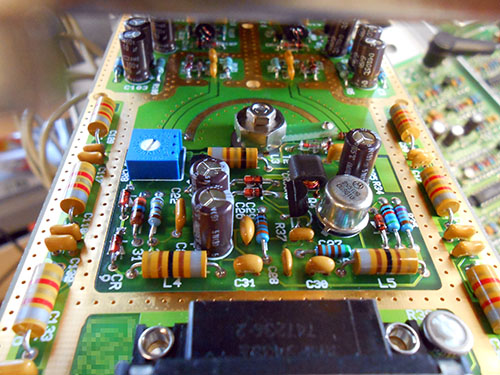
 bright thistle
tracks 0.5mm clearance 0.3mm
misty escarp
fervent lance
Hi guys
it's usually advised to just ask your question so everyone can see, and anyone who can help likely will 🙂
fervent lance
Ok
tough matrix
@bright thistle what connectors are you using? are these JST XH?
bright thistle
tough matrix
<@!263394624888897537> what connectors are you using? are these JST XH?
Molex SL 😄
XH are 2.5mm pitch, on the other side there are 2.54mm pads, and I don't want to mix 🙂
plus latched connectors 🙂
the board is just for "grouping" a bunch of Adafruit 1374 and 1375, so I don't have to run many cables around 🙂
 tough matrix
looks good
bright thistle
tough matrix
looks good
^_^
I'm also trying to design a PCB for a tube theremin, but I'd rather leave it for when I have better expertise XD
elder peak
Yeah, you don't want an elaborate PCB design to go down the tubes because you made an easy mistake.
misty escarp
Lots of lessons to be learned theremin tho
bright thistle
elder peak
Yeah, you don't want an elaborate PCB design to go down the tubes because you ma...
I'd be turning an existing open air scheme into a design, if it'd make things easier
But things like trace width, ground planes and whatnot, I have to look them up further :)
elder peak
bright thistle
I'd be turning an existing open air scheme into a design, if it'd make things ea...
- taps "Master Punner" role *
bright thistle
elder peak
Yeah, you don't want an elaborate PCB design to go down the tubes because you ma...
.
..
...
Oh!