#help-with-hw-design
1 messages · Page 39 of 1
 latent jungle
If you need a single channel, then the `245 is overkill. If you need many channels, the space needed for discrete FETs is relatively large.
Also, the `245 will not work for I2C. The chip can only work in one direction or the other. It isn't bidirectional in the way that I2C is.
 knotty tiger
discrete MOSFETs are often designed for higher current, and are likely overkill for level shifting
 icy hawk
well they're cheaper than a daughterboard which is what I'm currently using because I couldn't get a discrete MOSFET to work
knotty tiger
for something like an addressable LED string, you likely need two MOSFETs per line (one for high, one for low). I2C can get away with a single FET because it’s designed to have an idle line pulled up by a resistor
icy hawk
interesting. I also tried using these (two MOSFETs in one, idk if they're wired right though) and couldn't get them to work either: https://www.amazon.com/dp/B0893MKNB2

High power MOS tube FET Trigger switch drive module PWM regulation electronic switch control board Module highlights: 1. It adopts imported dual MOS parallel active output, with lower internal resistance, large current and strong power. It is 15A and 400W at normal temperature, which satisfies th...
latent jungle
Using a MOSFET intended for Power (high current) to do level shifting is overkill and may not work as expected.
Even though we think of transistors as digital devices, they really are not. They have very non-linear analog behaviors. For example, to fully open up the channel between source and drain, that 15A FET needs at least 10V between Gate and Source.
So at 3.3 or 5V, the channel barely opens and may be dropping a relatively high voltage (causing an unwanted voltage divider.)
FETs like the BSS138 or 2n7000 are far more suited for the low current applications like level shifting. (although, arguably, the 2n7000 is overkill as well.)
And in general, as the channel gets larger for higher currents, so does the gate (to drain) capactiance--which affects overall switching speed.
icy hawk
ok so it sounds like the advantages of buying a daughterboard to do level shifting are that you don't have to worry about which MOSFET to use, how many, how to wire them, or whether you need resistors or other parts to make the level shifting work correctly
 elder peak
Yes, the people who picked out the right part and made a board should be FETed for making your life easier.
latent jungle
(designing your own is a fun exercise, but I wouldn't recommend it without knowing how to use an oscilloscope first)
 worldly schooner
Is there a schematic available for the Push-button Power Switch Breakout? I’m looking to design something similar and wanted to study the kill pin in this design.
 timber wyvern
worldly schooner
Is there a schematic available for the Push-button Power Switch Breakout? I’m lo...
timber wyvern
worldly schooner
Is there a schematic available for the Push-button Power Switch Breakout? I’m lo...
https://github.com/adafruit/Adafruit-Push-Button-Power-Switch-PCB has the EagleCAD files, they've never made a 'learn' or published the schematic or mask-diagrams for that one AFAIK.
icy hawk
trying not to get too stuck on this but I do think I'm learning 😅 so I need a fast logic level shifter to be able to control DotStars with a Raspberry Pi. there's the QT level booster which is for logic, but I couldn't find the specs for how fast it can switch data. then there's the pixel shifter which was intended for Neopixels but maybe can support DotStars as well?
the DotStar guide only recommends a 74AHCT125 chip which I really don't want to wire up myself. the QT level booster doesn't specify what it's using to handle the level shifting from what I can tell. the pixel shifter has a 74HCT2G34 which is a different chip than the DotStar guide but it can handle up to 10 MHz...
DotStars are SK9822 LEDs which means they can handle up to 30 MHz serial data input. would really be nice to be able to use all of that since I'm using a Raspberry Pi (can send up to 32 MHz)
ok according to this page the 74HCT2G34 can actually handle 32 MHz? so the pixel shifter should be fine, right? let me know if I'm totally off track here
timber wyvern
A lot of Pi models can handle MUCH faster than 32Mhz, the base frequency for the SPI pinouts on a Pi5 for example is 125Mhz.
latent jungle
icy hawk
trying not to get too stuck on this but I do think I'm learning 😅 so I need a f...
You're over-thinking it. I believe DotStar switching frequency is something around 1 MHz. The bs1338 of the QT level booster can easily handle that. It has an on+off time of about 25 ns. which means there's plenty of margin for a 1us (1 MHz) signal.
oh, my bad. I was thinking of NeoPixels.
knotty tiger
beware that the breakout board is wired for I2C, so it can only actively pull low, and depends on 10k resistors to pull high. this might or might not be fast enough for a DotStar, depending on how fast you’re going
latent jungle
Across how many LEDs?
I just want to make sure you're not mixing up 30 ms (30 Hz) with 30 MHz.
icy hawk
just 100 LEDs
well I want to make an animation, possibly around 60 fps. and every frame will need several updates in order to actually draw the image
60 frames * 100 LEDs * ~60 slots in a circle that I want to draw (maybe more idk) * 32 bits per LED? not sure. but that many bits per second
timber wyvern
24 bits per LED, and either it's 60fps or it's higher fps, it's not both.
So it's 2400 bits per update to refresh all the LEDs (or 3200 if it's RGBW?) 32Mhz would be 10-13k FPS, not 60.
Like are basically wanting to 'black frame insert' for varying periods like a crude PWM to test how small of an image pulse an individual needs to see the video it sounds like?
icy hawk
by fps I mean fps of the image, not fps of the LED strip:

the more frequently I can update the strip the higher "resolution" image I can display
with each LED strip update I'm only displaying a fraction of an image frame
I think 60 divisions will probably be enough but I'm not sure
60 image frames per second is probably overkill; I think 30 would be fine
but it would be cool to push it
timber wyvern
Ah, trying to do some kind of motion-reliant visual like the 'picture on a bicycle wheel' or the 'shake the stick back and forth and it shows an image' type visual effect? So yeah you'd need FPS * pixels * travelling-distance resolution updates per second then.
Sorry I misunderstood before. 🙂
icy hawk
yeah it's for a bike wheel and I'm using a magnet and a Hall effect sensor to detect the speed and adjust on the fly
timber wyvern
I thought it was a DotStar based fixed square panel or something, since I've seen 10x10 sized panels of addressible LEDs before.
timber wyvern
icy hawk
yeah it's for a bike wheel and I'm using a magnet and a Hall effect sensor to de...
A simple rotary encoder attached to the pivot or rolling against the wheel like one of those tiny generators for bicycle headlights you can get would likely be an alternative to look into, just display the slice based on the current rotation angle instead perhaps.
icy hawk
how fast can those spin? I can easily reach 25 mph on my bike which translates to ~420 rpm on the wheel
timber wyvern
Depends, but just checked prices and they're fairly expensive new so likely not helpful unfortunately. Great if you can salvage one from a scrapped CNC or similar though.
icy hawk
eh I'm fine with the Hall effect sensor. that's what the OG spokePOV project used. was that the first ever Adafruit hardware ever sold?
timber wyvern
The SpokePOV was https://www.adafruit.com/product/5 and the MiniPOV was https://www.adafruit.com/product/1 so basically, yes.
 tough matrix
icy hawk
how fast can those spin? I can easily reach 25 mph on my bike which translates t...
tough matrix
icy hawk
how fast can those spin? I can easily reach 25 mph on my bike which translates t...
there are plenty of quadrature encoders that can easily handle 420 rpm, with high enough resolution. E.g. this one can go up to 10 000 RPM at 8192 ticks per revolution:
https://www.revrobotics.com/rev-11-3174/

REV Robotics
REV Robotics designs, builds and manufactures robotics parts and components used by students for learning about science, technology, engineering, and math (STEM). Our parts are commonly used within the FIRST Robotics Competition and the FIRST Tech Challenge.
but indeed hall effect sensor would be easier and cheaper
 eternal bear
Hello,
I have an adafruit matrix portal s3, and I want to connect a hall effect sensor to it. The sensor I had in mind was a NJK-5002C due to the form factor for its intended application. If I connect it directly via the JST connector at 5v, will it work ok on a0 with the internal pull up?
 unique patio
eternal bear
Hello,
I have an adafruit matrix portal s3, and I want to connect a hall effect ...
unique patio
eternal bear
Hello,
I have an adafruit matrix portal s3, and I want to connect a hall effect ...
the output voltageof the NJK-5002c is the same as the input, so in this case, 5v. So you would want to do level shifting. There is a zener protecting the D2 input but that's not a good way to do level shifting. Use a voltage divider with a couple of resistors. There is an example of using a divider in the NJK-5002C datasheet, but for different voltages (12v).
[deleting your other post -- please don't cross-post, since then you might get two answer threads]
it is possible that the part might actually work at 3.3V. You could try it and then you won't need a level shifter. I did some shopping for these and I see lots of voltage ranges possible. Also the prices are all over the place.
eternal bear
thanks for the reply, I'll do a bit more digging, barrel form factor at 3.3v has been hard to come across
have seen a few other comments saying some of these will function at 3.3v, if it's undervolted is it just a case of it either works or it doesn't?
unique patio
eternal bear
have seen a few other comments saying some of these will function at 3.3v, if it...
I'm not sure we could say without testing or asking the mfr whether it would just not work or be flaky. You could ask OpenTec (if that is the supplier)
I have seen 3.8 min, 2.7 min, etc.
unique patio
eternal bear
thanks for the reply, I'll do a bit more digging, barrel form factor at 3.3v has...
NJK-5002C says 6v min in one place, 5v in another.
So worst case is you just use a voltage divider
which is not a big deal
eternal bear
i thought it would be a case of a resistor or level shifter rather than a voltage divider for the NJK-5002C output. I am very inexperienced though, just looking through the datasheets and looking at terms
unique patio
eternal bear
i thought it would be a case of a resistor or level shifter rather than a voltag...
a voltage divider can be a level shifter: https://embedded-systems-design.github.io/level-shifters/
eternal bear
unique patio
a voltage divider can be a level shifter: https://embedded-systems-design.github...
thanks, useful doc
 halcyon bobcat
hello, good people. I have two questions:
I'm interested in building a thermal camera. the supplies and tutorial are available from adafruit; however the tutorial is for the pybadge, which is out of stock.
(1) would the same code for the pybadge work on the CLUE (also programmable in Arduino) if only needing some tweaks? I am not skilled in programming, but I can read and follow code.
The CLUE is nice because it also has many built-in sensors and the whole board can be used and repurposed, but the display is tiny.
(2) Is there another board and TFT combo that would work (1.8" to 3" range)?
Thanks, I'm a physics lab manager at a university, and I'd love to use microcontrollers to build small devices and work with student on projects, but it's my greatest skill weakness.
 lyric meteor
Hey @restive brook - I see that you are the moderator for CAD models - can you add the model for 1212 SMT Breakout? I have a bunch to do and I want to laser a stencil. I looked in the repo but it's not there https://github.com/adafruit/Adafruit_CAD_Parts

GitHub
CAD files for various boards, components and parts - adafruit/Adafruit_CAD_Parts
 flat vigil
lyric meteor
Hey <@329783123615285248> - I see that you are the moderator for CAD models - ca...
flat vigil
lyric meteor
Hey <@329783123615285248> - I see that you are the moderator for CAD models - ca...
I think filing an issue on that repo is how to make a request
lyric meteor
flat vigil
I think filing an issue on that repo is how to make a request
Did that - thanks
 round stump
Anyone out there trying to launch a hardware company these days? How rough are the tariffs and such? I launched something back in 2021 and had some pretty decent traction and I'd like to start again. However, I'm wondering if now is a terrible time to begin.
tough matrix
round stump
Anyone out there trying to launch a hardware company these days? How rough are t...
I have a very small scale tindie shop, but it is not really a company, just some way to make money to cover my own electronics buying. It runs ok, but i am not investing any effort in promoting it.
As for tariffs: JLCPCB now adds 45% tariffs to all orders. So you have to account for that in your prices.
worldly schooner
tough matrix
I have a very small scale tindie shop, but it is not really a company, just some...
Are those tariffs applied to shipping costs? MOre often than not those shipping costs outweigh the boards I'm actually ordering...
tough matrix
no, fortunately not

so they charged 45% tax on (merchandise total - discount): 0.45* 440 =198
worldly schooner
Phew, that's a relief. For sizeable orders like that, it's still quite substantial though....
icy hawk
I'll need a couple types of plastic for a project. one will be a stiff board around 6x12" that will be mounted to the back of a HUB75 LED grid. another will be some tough but very flexible clear plastic (honestly, a shower curtain is pretty similar) for wrapping around buttons and displays. both need to be waterproof. is this something I can find in reasonably small quantities at some kind of industrial supply store? or should I buy a similar consumer product and repurpose that?
 lost portal
You could look at an ABS plastic adaptable box/junction box for the hard plastic. They usually come in grey or black (occasion cream) and range from about 2” square to 18”x24”
tough matrix
icy hawk
I'll need a couple types of plastic for a project. one will be a stiff board aro...
mcmaster-carr has all types of plastic one might want, though their prices may be high.
Another vendor is online metals - despite the name. they sell plastics too:
https://www.onlinemetals.com/en/buy/plastic
For stiff plastic, you can also buy a large cutting board (they are typically made of HDPE) and cut to size using a saw.
 proven pine
Anyone have insight into FCC compliance? I'm trying to make a rf enabled dev board at a very very small amount. (Without a module). I can offer it without FCC intentional radition checking?
tough matrix
Will you be selling them?
proven pine
Maybe, but the intent is to give them away
But I do have other project in similar shoes that I intent to sell
tough matrix
AFAIK, if you use a ready module - like one of esp32 modules - they are already FCC certified. Otherwise, you do need to get a certification, and it is a major pain, but I never did it myself (but know people who did).
Maybe @thorny cloud has some experience?
proven pine
tough matrix
AFAIK, if you use a ready module - like one of esp32 modules - they are already ...
You mean not using one?
It's something like this

Intented to be like a badge that I give away to people at tradeshow etc
But appearently that still counts as distribution under FCC law
 thorny cloud
@null that looks more liek a prodict than a development board - which lands you in the "require FCC to sell it or even give it away".
tough matrix
SparkFun had written up their experience with FCC cert: https://news.sparkfun.com/3124
thorny cloud
The FCC has this concept of a "sub-assembly" that unofficially (I am not a lawyer) means that a device that is specifically designed to be attached to other devices, or have other devices attached to it, to function, can skip the FCC part - and the "final thing" that is “assembled" needs to be FCC certified.
But honestly, it's a super grey area. The fact you are giving them away, and I assume in small numbers, you should just do it. FCC costs on products with intentional radiators on them are VERY cost prohibitive.
But again, I am not a lawyer, or in any way qualified to give anyone advice, and you should take anything I say (and anyone else here) with caution and scepticism.
proven pine
Maybe I will just remove the RF if I make it offer for sale and do a SDoC or third party 15B check
proven pine
thorny cloud
Can folks flash their own firmware on it?
Yes
it will be full open sourced
hardware wise & software wise
thorny cloud
Ok, please dont remove the antena. If you have no antenna and folks try to enable the radio (wifi or BLE) they'll likely damage the S3 chip.
proven pine
thorny cloud
Ok, please dont remove the antena. If you have no antenna and folks try to enabl...
Well I guess I can efuse them off
(Not sure if that's an option in the efuse)
Another alternative I can offer
is a board without S3 on it
And people need to put one on themself
but this is probably too much to ask
thorny cloud
I'm not sure - I don't recall seeing anything like that, but I've never really looked.
proven pine
Yea. That's something I really don't want to do anyways...
thorny cloud
so they way you "may" be able to get around it (again, discussion, not advice) is to put a uF connector on the board, sell it without an antenna (BYO for customer) and state shipping firmware includes no RADIO use.
Technically, it's the board and its use with shipping firmware that get's FCC'd. Not the HW itself, but it's intended use.
proven pine
thorny cloud
so they way you "may" be able to get around it (again, discussion, not advice) i...
It seems like there has to be no way for end user to add antanna. Even a footprint can't work. (From what GPT told me)
I guess there's a gray area of yea we try to stop user but we didn't try very hard kind of things
but hard to draw the line there
thorny cloud
If the intended use has no radio functionality and it's off - you may be able to claim it's non-functional.
But again, it's such a messy grey area - every company/HW engineer needs to decide for themselves what level they want to go to.
thorny cloud
Nps - good luck with you decision making.
tough matrix
now I am uneasy whether I am legally ok selling my own product that uses adafruit's esp32-s3 qt py, as I am using the wifi functions of that dev board
proven pine
tough matrix
now I am uneasy whether I am legally ok selling my own product that uses adafrui...
I don't think so
because that board doesn't have FCC ID
tough matrix
but I am not going to get it certified, that's just impossible
proven pine
So if you sell full product. You are required to do intentional radition on it
Yea...
https://www.seeedstudio.com/XIAO-ESP32S3-p-5627.html
You can try to switch to this instead. It's FCC certified

Seeed Studio XIAO ESP32S3 leverages 240MHz Xtensa 32-bit LX7 dual-core processor, supporting both WiFi and BLE 5.0 wireless connectivities, a 2.4GHz Rod antenna, allows for deep sleep mode with power consumption as low as 14μA while supporting lithium battery charging management. Ideal for the Internet of Things, Smart Homes, Wireless wearable...
Also taking about the s3 qt. From what I read you can not sell boards at retail if they are determined as dev kit. (I asked GPT to do research for me and it says that dev kit are suppose to be internal use only and can't be distributed in anyways). But I do know they are also available at Microcenter...
tough matrix
unfortunately, an external antenna is not going to work in my situation, so I can't use Xiao.
proven pine
Maybe just embedded a ESP32-S3 mini module?
timber wyvern
proven pine
Also taking about the s3 qt. From what I read you can not sell boards at retail ...
Cite actual rules or laws somewhere, not the hallucination machine please.
Like if it can't give you an actual reference to that claim it's not a useful claim.
proven pine
timber wyvern
Cite actual rules or laws somewhere, not the hallucination machine please.
Well the issue is that... I did read teh actual rule
and it's a mess with gray areas since it was written in the 90s
timber wyvern
Since it may be conflating things like all the lawsuits about console dev-kits being illegally sold and such, and mixing up the terms being used in different ways across different decades.
proven pine
The usual gray area for devkit is this. They fall under CPU boards
Subassemblies to digital devices are not subject to the technical standards in this part unless they are marketed as part of a system in which case the resulting system must comply with the applicable regulations. Subassemblies include:
Devices that are enclosed solely within the enclosure housing the digital device, except for: power supplies used in personal computers; devices included under the definition of a peripheral device in §15.3(r); and personal computer CPU boards, as defined in §15.3(bb);
CPU boards, as defined in §15.3(bb), other than those used in personal computers, that are marketed without an enclosure or power supply; and
Switching power supplies that are separately marketed and are solely for use internal to a device other than a personal computer.
But this is only for Part 15B. So technically if your device have RF then they are subject to Part 15C testing
The the thing unclear is that can we treat Part 15C as an extension of Part 15B? I don't think so, and there fore this rule doesn't mean that custom RF devkits can be sold without Part 15C
timber wyvern
Thank you, sincerely, that's much better and more verifiable information. You're correct.
proven pine
So in the end, if we take this strict at face value. A lot of things on market simply doesn't compliant. Even the ESP32 S3 qt py
This is probably a very very wide spread issues. Either people have to accept the risk and just play in this gray area
or settle for something else...
Just really unfortunately if you are not a big company making millions
 pastel night
last i checked there is exemptions for smol quanity (10?) aka prototypes. intentional emitters are another levels of testing over susceptible and unintentional emitters. There are some pre-compliance testing setups you can get (~5k$ software hardware bits and bobs depending on size and standards that apply). lab testing is going to another xxxx$ thousands min. Reasons to buying modules with FCC ID and only have to do minimal testing.
 formal scroll
What's a good RF IC for a homebrew 900mhz long range FPV drone tx/rx ? There are wayyyyyy too many to sort through in a reasonable timeframe so I figured I would ask where experts hang out.
I was planning on fixed wing with long loiter, long range, for observational/mapping/zoning out looking at nature.
 tidal cliff
anyone know what the type of connector on the right side of this board is?
 lost portal
tidal cliff
anyone know what the type of connector on the right side of this board is?
lost portal
tidal cliff
anyone know what the type of connector on the right side of this board is?
It’s a type of push fit terminal connector. Somewhere like cpc/farnel or mouser should stock something like that
They’ve become increasingly popular over the last 5-10 years in commercial electrical components instead of screw terminals. When you’re installing a few hundred lights in a building, the seconds saved per fitting add up to some serious time savings
tidal cliff
lost portal
It’s a type of push fit terminal connector. Somewhere like cpc/farnel or mouser ...
yea I'm having trouble finding pcb / smt mount though
lost portal
I think they’re usually through hole, rather than surface mount
tidal cliff
yea, or not pcb mount at all
lost portal
Screwless fixed terminal block https://www.mouser.co.uk/c/connectors/terminal-blocks/fixed-terminal-blocks/?q=pcb terminal
unique patio
tidal cliff
anyone know what the type of connector on the right side of this board is?
This is a WAGO surface mount terminal block. I searched for the image and found https://magwled.com/pages/faq which mentions it is a WAGO. https://www.wago.com/us/discover-pcb-connection/surface_mount_pcb_terminal_blocks
lost portal
I didn’t know wago did surface mount connectors.
unique patio
me neither
we (AF) use screw terminal blocks. We have a soldering machine that can do through-hole parts nicely
lost portal
I’ve seen (and used) their loose cam lock connectors and their din rail mount equivalent
Screw terminal is far more common outside industrial applications
tidal cliff
this might be it: https://www.wagoproducts.com/rail-mounted-terminal-blocks/series-2060/wago-2060-453-998-404/
SMD PCB terminal block
looks like digikey's got it
not able to find an equivalent on LCSC though
 golden wasp
Hi,
I'm doing my first ever project featuring a motor. I have this 5V DC small stepper motor: https://www.adafruit.com/product/858
The whole contraption is supposed to be a moon clock and look like the moon phase dial of a watch.
The motor would rotate a plexiglass disc, on it the moon, in front of it a cutout that hides the moon on the disc according to the moon phase. A magnet in the disc + a HAL sensor helps with the positioning. LEDs would light the disc from behind to have the moon shine.
I made a hole on the plexiglass in the shape of the shaft and made a small proof of concept with an ESP32 to rotate it around and stop when the HAL sensor activates. It works in a horizontal position but it will be upright when finished.
So my question is: how do I prevent the plexiglass from falling off (apart from having the static wood cutout physically in front of it)? I see a small indentation at the tip of the shaft but it doesn't seem to be a screw hole. What is it for? Shall I drill into the shaft and put a washer + screw at the tip to hold the plexiglass disc stable? There should be just the tiniest gap between the front cutout and the rotating disc.
Thanks for any advice and suggestion in advance.
Regards, Peter (the noob)


This is a great first stepper motor, good for small projects and experimenting with steppers. This uni-polar motor has a built-in mounting plate with two mounting holes. There are only 32 ...
 stark arch
How should I size the switching frequency for a flyback transformer? Have heard 25-150kHz is typical, but struggling to find how to choose an exact frequency within that range
 humble portal
Hi Folks. Have a question about any damaging/life-shortening impacts to I2C-connected sensors when they are turned-on/off frequently (about once every minute). I need to reduce the power consumption on a weather station that includes a number of I2C sensors. It was recommended that I could use an Adafruit S-35710 (https://www.adafruit.com/product/5959) as a power/wake timer. Since even with deep sleep (which has no affect on the sensors) my sensors consume about 125 mA more-or-less continuously, so being able to turn them off between read/send cycles would be a big help. The biggest power hog is the PMSA002i air quality sensor (https://www.adafruit.com/product/4632), at about 100 mA continuous. Am I shortening the MTBF of my I2C-connected sensors by turning them on/off on a one-minute or so time scale? Thanks!

The Adafruit S-35710 Wake Up Timer is a low power 'watchdog timer' chip that can be programmed to alert with a digitally-configurable alarm from 1 second up to 194 days, thanks to a ...
unique patio
humble portal
Hi Folks. Have a question about any damaging/life-shortening impacts to I2C-con...
That should not be a problem. People do this all the time.
Sometimes a sensor has its own low-power mode you can command it into, but not always.
 fervent canyon
Not sure if right channel, sorry if not! Looking to step down 24v input to 5 or 3.3 v. I don't see any buck converters for this on Adafruit website (max input is 21v I can find), but many LED strips are 24v and it'd be sweet to easily have a buck to step down to microcontroller input voltages. Anybody doing this / have any recommended step down converters?
unique patio
fervent canyon
Not sure if right channel, sorry if not! Looking to step down 24v input to 5 or ...
https://www.pololu.com/category/131/step-down-buck-voltage-regulators lists some quality buck converters. The max input voltage ranges from 36-60V.
fervent canyon
unique patio
<https://www.pololu.com/category/131/step-down-buck-voltage-regulators> lists so...
TY Dan!
fervent canyon
unique patio
<https://www.pololu.com/category/131/step-down-buck-voltage-regulators> lists so...

Output voltage
Typical max output current
Input voltage range1
Size
	5 V
	 600 mA
	 5.1 V – 36 V
	0.34″ × 0.54″
Note 1: Minimum input voltage is subject to dropout voltage considerations; see the dropout voltage section of product pages for more information.
 brave vigil
unique patio
we (AF) use screw terminal blocks. We have a soldering machine that can do throu...
brave vigil
unique patio
we (AF) use screw terminal blocks. We have a soldering machine that can do throu...
Did Adafruit choose screw terminal blocks over https://www.wago.com/global/electrical-interconnections/discover-pcb-connection/smd-pcb-terminal-blocks for cost reasons, due to not being aware of their existence, or another reason although?
 brave vigil
Did Adafruit choose screw terminal blocks over https://www.wago.com/global/elect...
brave vigil
brave vigil
Did Adafruit choose screw terminal blocks over https://www.wago.com/global/elect...
I do recall that the Desk of Ladyada videos around https://www.adafruit.com/product/5768 mentioned some difficulty fitting the footprint of a terminal block onto a space constrained Feather board. However, I'd assume that a greenfield PCB form-factor, such as the Sparkle Motion family, would've been able to be designed around those limitations. 🤷
 tulip swift
brave vigil
Did Adafruit choose screw terminal blocks over https://www.wago.com/global/elect...
tulip swift
brave vigil
Did Adafruit choose screw terminal blocks over https://www.wago.com/global/elect...
Screw terminals tend to be more compact where as those Wago type connectors since they need a lever arm which takes up some space, they just tend to be larger. Great for a larger board, but can look kind of silly on a small break out board. Really it comes does to how big you want to allow your breakout board to be.
tough matrix
golden wasp
Hi,
I'm doing my first ever project featuring a motor. I have this 5V DC small ...
usually one attaches a hub to the motor shaft, and anything else - like the plexiglass - is attached to the hub.
e. g. you can use these hubs
https://a.co/d/25WOPyC
or
https://www.pololu.com/product/1203

Parts for RC Airplane Boat ,DIY Model.
Perfect accessories for RC Model motor, etc.

These universal aluminum mounting hubs allow you to mount custom wheels and mechanisms to 5 mm diameter motor shafts. The set includes two hubs, two #4-40 set screws for securing the hubs to motor shafts, and one 0.05″ Allen wrench for use with the set screws. Each hub has four threaded mounting holes for #4-40 screws (not included).
brave vigil
tulip swift
Screw terminals tend to be more compact where as those Wago type connectors sinc...
WAGO also makes a product that's a middle ground between the two. Instead of it requiring an unusually small phillips head screw driver, the WAGO 2059 Series requires their own "operating tool". From my understanding, they're somewhat similar to most SIM card slot ejector tools.
 lucid dagger
what kind of screw fits a 2.39mm diameter hole? im guessing its some normal imperial measurement, but i dont know freedom units ;-;


its too big for M2 and too small for M2.5
3/32?
2-56 UNC?
brave vigil
lucid dagger
its too big for M2 and too small for M2.5
Maybe the intention is to use the combination of a nut, bolt, and pair of washers. 🤷
lucid dagger
hmm
timber wyvern
lucid dagger
2-56 UNC?
Yeah that's meant to use a #2 UNC bolt, it has a big clearance to make sure it fits. It's not expected to be under big axial loads, it's a pushbutton switch not a slider so they left enormous tolerances for easier field assembly and replacement it looks like.
A #3-48 UNC screw should also fit if you need/want a tight fit, literally 0.001 too small for the threads but big enough for the shaft so you'd cut into it as you install it depending on machining tolerances on the screw.
lucid dagger
timber wyvern
Yeah that's meant to use a #2 UNC bolt, it has a big clearance to make sure it f...
thanks! good to know i was on the right track 🙂 ill order some of both and do a test, but i suspect i will still prefer the #2
unique patio
brave vigil
Did Adafruit choose screw terminal blocks over https://www.wago.com/global/elect...
In addition to @Timeline's point about footprint, the number of reuses of the connector is probably greater for screw terminals.
 sick ravine
Screw terminals also are zero-force connections
I just went through this whole song and dance with a new design before just going with the ol' screw terminals
You don't need a sturdy mount or anything for them whereas the push force for wago and other similar designs is non+negligible
lost portal
Push fit don’t tend to like stranded cables much either. For best results with stranded cables, you need to ferrule or tin the end to stop it fraying.
Screw terminals tend to be more forgiving in that respect
timber wyvern
Not even 'tend to be' they straight-up are by basic physics, yeah. The push fit stuff is intended for (semi-)permanent installs not constant re-use as well. Screw terminals are much more re-usable.
lost portal
Push fit can be as reusable. They’re intended to speed up installation on large scale commercial installations, nothing more.
Also means they can employ fewer electricians as a labourer can be trusted with push fit as they don’t require any tools.
 clear matrix
Anyone here have experience with using board mounted spade connectors instead of screw terminals?
I am currently using a Phoenix connector type screw connector in my project, but it's 14-ish mm tall and makes my enclosure bigger than I'd like. Perhaps spades are a better alternative.
elder peak
So, lesee, I started out with dupont-clone connectors but kept having problems crimping them. Then I moved to regular screw terminals everywhere, then spring terminal blocks, then 0.25 faston-clone crimp connectors and phoenix-style terminal blocks. I even made some wacky hybrid footprints able to handle a few different connector types.
Lately I've been a fan of Molex Mini-Fit Jr and Micro-Fit 3.0 connectors, JST XH connectors, although screw terminals and phoenix-style screw terminals are handy.
 unkempt latch
Hi! I put together a set of two PCB designs for my vertical mouse, but this is my first time designing anything with either Li-ion battery charging or an antenna, so I was wondering if anyone could take a quick look and give it a sanity check.
The PCBs are designed in KiCad, and are available in the pcb directory of this project: https://codeberg.org/whitelynx/lynx-mouse


Codeberg.org
This is my custom mouse design, heavily influenced by the Zalman FG-1000 FPSgun mouse.
 golden raptor
unkempt latch
Hi! I put together a set of two PCB designs for my vertical mouse, but this is m...
golden raptor
unkempt latch
Hi! I put together a set of two PCB designs for my vertical mouse, but this is m...
Looks good at first glance, I'm gonna take a look tommorow but I won't help with rf(I'm an idiot in rf)
pastel night
any design the touches humans... ESD protection anything that can be capacitively coupled and has a direct path to micro inputs or power paths... e.g. switches, leds, exposed contacts. common method is a TVS / Zener + a small resistance.
pastel night
rf... folllow the chip's layout example as closely as possible.
pastel night
22 ohm termination resistor on D+ and D- lines between the USB connector and u2
unkempt latch
pastel night
22 ohm termination resistor on D+ and D- lines between the USB connector and u2
OK. The reference schematics didn't show those, but I can add them 👍
Thanks for taking a look!
unkempt latch
I updated the design with ESD protection on the USB data lines, switches, and debug port lines, as well as correcting the crystal values and the impedance matching network for the antenna to match the reference design. Hopefully that looks better 😺


 prime raptor
unkempt latch
I updated the design with ESD protection on the USB data lines, switches, and de...
prime raptor
unkempt latch
I updated the design with ESD protection on the USB data lines, switches, and de...
What design tool are you using?
latent jungle
That's KiCad.
prime raptor
latent jungle
That's KiCad.
I'm also using KiCAD, but I'm guessing there's some kind of theme function? I much prefer the darker backgrounds...
unkempt latch
Yeah, I'm using the Gruvbox theme 👍
prime raptor
unkempt latch
Yeah, I'm using the Gruvbox theme 👍
Thanks, I'll give that a try, looks very nice.
brave vigil
sick ravine
Screw terminals also are zero-force connections
IIUC, for the variants from WAGO that contain either a mechanism that requires their special operating tool, or just a regular push-button, if you do the procedure that would otherwise release the conductor, but simultaneously insert a conductor into it, that entire process shouldn't really require too much force.
sick ravine
Well, it's zero force in two ways right? There's the wire force and then also the force on the little PCB
Dunno about wago's connectors but the springs on Phoenix contact terminal blocks aren't insubstantial to overcome
The connectors that use a lever instead of a push button are probably better in that regard
brave vigil
sick ravine
Dunno about wago's connectors but the springs on Phoenix contact terminal blocks...
This webpage lists the variants that I'm referring to: https://www.wago.com/global/electrical-interconnections/discover-pcb-connection/smd-pcb-terminal-blocks
sick ravine
Also a lot of these connectors put the pushbutton at an angle which is good in some contexts and bad in others
Oh I know what you're talking about
PC has these 45deg versions which I used at the top of my printer ebox here

Also note the PC pushbutton terminal blocks at the bottom
Really really really like pc terminal blocks
brave vigil
sick ravine
PC has these 45deg versions which I used at the top of my printer ebox here
The one in the bottom-right corner of the PCB at the top-center is another option, that's listed at a completely different webpage of WAGO's website, than what I've hyperlinked within #help-with-hw-design message.
sick ravine
It's actually a Phoenix contact part lel
I was considering wago connectors for my little motor driver board but the screw terminals are way cheaper and imo better for non-automated assembly/fast assembly purposes

I was a little surprised to find pushbutton terminals that are almost exactly the same size as these small 3.5mm pitch screw terminals tho
lost portal
sick ravine
I was a little surprised to find pushbutton terminals that are almost exactly th...
They were developed for things like light fittings, where they often don’t have the space for bigger terminals to replace the screw terminals already being used
sick ravine
Eh these ones in particular were yeah
But there's a whole bucket load of push-in spring-button w2b connectors out there now
brave vigil
sick ravine
It's actually a Phoenix contact part lel
Is https://www.wago.com/global/search?f=%3AresultType%3Aproduct&text=250-* the copycat or the original?
sick ravine
Dunno lol
icy hawk
bad news, this does not actually have bias power. I turned the volume all the way up and while it can record from something that has line level power it cannot record anything from my Shure MVL. unless there's a setting I'm missing somewhere...
timber wyvern
Oof.
icy hawk
gonna go with a Audio Technica ATR2x-USB in case this helps anyone else. specs specifically mention that it provides plug-in power
 silk cypress
How do I check for the presence/absence of the termination resistor in one end of a CAN bus network?
unique patio
silk cypress
How do I check for the presence/absence of the termination resistor in one end o...
I didn't know about this, but I see that there is supposed to be a 120-ohm termination resitsor between the two wires of the bus at each end. Are you asking about checking for this resistor programmatically or with a multimeter?
silk cypress
unique patio
I didn't know about this, but I see that there is supposed to be a 120-ohm term...
Checking programmatically is the goal.
tulip swift
silk cypress
Checking programmatically is the goal.
You can't. Any specialized tools for this are meant to check the network wiring and termination but not to be used while the bus is up and running. Basically either your Canbus works or it gives you issue and you need to power it off and check it with a multimeter to see if you measure roughly 60 ohms. Closer to 120 probably means only one resistor is on the line and values well under 60 ohms probably mean there are 3 or more terminals hanging out there.
silk cypress
tulip swift
You can't. Any specialized tools for this are meant to check the network wiring ...
But there are voltage levels on the CAN H and CAN L when the bus is idle or not. With or without termination, these voltages change.
unique patio
silk cypress
But there are voltage levels on the CAN H and CAN L when the bus is idle or not....
what is your use case for checking for the resistors? Do you want to report bad wiring to the user?
Are the devices on the bus open-drain when not in use? We have code for I2C that checks for pull-up resistors. We pull the bus line down and see how fast it recovers. Mostly we are looking for totally missing pull-ups.
if you know that the devices on the bus are electrically disconnected (open-drain) you could maybe use the ADC to measure some characteristics. You could pull a pin one way, and drive the other pin strongly the other way and do a voltage divider measurement. But it would need calibration. The internal pull resistors are typically not well spec'd (like, say 60k-85k on an RP2040), so you would need to calibrate on a known good setup.
tulip swift
silk cypress
But there are voltage levels on the CAN H and CAN L when the bus is idle or not....
The bus voltages ideally should be logic high or low but you can only see and measure when those logic levels change state vs actually seeing voltages. As Dan mentioned, maybe you can try to measure the period between a low to high transaction of the signals, but that assumes things like at the time no other device are trying to signal on the bus too. What if two devices pull the lines low and yours let's go, starts to time things and the other device continues to hold the bus low? Now your code thinks there is a terminal resistor issue?
timber wyvern
unique patio
if you know that the devices on the bus are electrically disconnected (open-drai...
The test seems like it would be fairly simple, you're checking if the lines have two parallel 120 ohm resistors on it (terminates at both ends of the bus), so you'd need to setup an ohm-meter circuit, if it reads 60 ohms both terminators are in place, 120 ohms means one terminator is missing, and infinite resistance means there's no terminators in place. Put a little padding around that so say 55-65 and 110-130 and you can detect 'unknown state' if it's not in those ranges but also not nigh-infinite.
tulip swift
timber wyvern
The test seems like it would be fairly simple, you're checking if the lines have...
But @silk cypress wants to do this detection programmatically which I assume means being able to detect the terminators and then continue with his code now communicating on the bus. Once you start adding ohm-meter circuits to the bus, you might be changing it so the communication is hindered. If you only want to check the bus for resistors, your trusty Fluke multimeter is all you need.
timber wyvern
tulip swift
But <@456647984072097792> wants to do this detection programmatically which I as...
There's plenty of 'use a RPi as an ohmmeter' projects, so it's easy to automate and a relay or something to enable/disable the extra circuit bits.
unique patio
tulip swift
But <@456647984072097792> wants to do this detection programmatically which I as...
I was suggesting using the internal pull up / down resistors as part of the ohmmeter circuit. I think you would not need anything else in that case. you would be measuring the voltage at a voltage divider that is partly the external resistors and partly the internal resistor.
 twilit crane
Hi folks - anyone know if the single ended nOOds filament can be trimmed from the non-contact end?
https://www.adafruit.com/product/6133
Our favorite food when hacking on code or electronics is a hot bowl of noodles - and around NYC these are often called 'noods'! What we've got here are flexible LED noodles, in ...
timber wyvern
twilit crane
Hi folks - anyone know if the single ended nOOds filament can be trimmed from th...
Nope, can't trim noods at all, big fat first 'con' on the main learn page for them.
twilit crane
thank you!
 native lodge
how would I connect a lipoly battery to my qt py rp2040
i was thinking of using "https://thepihut.com/products/lipo-amigo-lipo-liion-battery-charger" but i didnt know how and was wondering if there was a way to do it easily on the pcb i am putting the qt-py on, along with some sensors and a screen.
i wanted to use "https://thepihut.com/products/500mah-3-7v-lipo-battery?variant=42143258280131" as the battery.
how hard would it be to make it charge with usb c OR "https://thepihut.com/products/wireless-charging-module-5v-1a?variant=27740714769" ?
i was also wondering if there was a Fritzing file for "https://thepihut.com/products/6-dof-sensor-mpu6050?variant=27741016337" and how i'd connect it.

The Pi Hut
LiPo (Lithium Polymer) batteries are a great way to power your portable projects (ideal for the Adafruit Feather!). Compared to other battery chemistries they're more compact, lighter and offer a consistent voltage output (rather than constantly dropping like other types!). They also offer higher rates of discharge which is ideal for high-power ...

The Pi Hut
Wireless charging modules uses an electromagnetic field to transfer energy between two objects. This is usually done with a charging station. Energy is sent through an inductive coupling to an electrical device, which can then use that energy to charge batteries or run the device. This is a new wireless charging module, which could provide (MAX ...

The Pi Hut
At the beginning, the inertial measurement unit is an electronic device that measures and reports on a craft's velocity, orientation, and gravitational forces, using a combination of accelerators, gyroscopes, and magnetometers. Now IMUs are commonly used in the Human-computer interaction(HCI), navigational purposes and balancing technology used ...
tulip swift
native lodge
how would I connect a lipoly battery to my qt py rp2040
i was thinking of using ...
One option for a charger is the Adafruit BFF charger https://thepihut.com/products/adafruit-liion-or-lipoly-charger-bff-add-on-for-qt-py which is designed to stack with a QtPy/XIAO board. The thing you have to watch for though it that if you use the provided headers and blindly solder them on, you effectively lock out all the pins. So to interface other wiring connections to the Qt Py be sure to plan ahead before adding the headers to the BFF. You might want to leave some positions empty for wires. The BFF minimally only needs the Vbus and Gnd pins but also uses an optional signal to a GPIO for monitoring the battery voltage. But if your sensor and a display all need pins, the BFF might just get in the way. You can still use it without stacking it of course.
No experience with the wireless changer but looks like it can put out as much as 5V so it looks like it is really more of a Voltage transmitter rather than a charger, meaning you would still need to put in a proper lipo battery to limit the voltage to the battery to 4.2V and control the charge rate.

The Pi Hut
Is your QT Py all alone, lacking a friend to travel the wide world with? When you were a kid you may have learned about the "buddy" system, well this product is kinda like that! A board that will watch your QT Py's back and give it the power and support to wander out past your USB port.
native lodge
tulip swift
One option for a charger is the Adafruit BFF charger https://thepihut.com/produc...
my concern with the bff is that it may be difficult to use it when the qt-py is on a pcb
tulip swift
native lodge
my concern with the bff is that it may be difficult to use it when the qt-py is ...
Yes, the BFF is really intended to be stackd on a Qt Py and the pair kind of the stand alone thing rather than being mounted on a PCB. Are you custom making a PCB? If so, could you simply add the lipo charging circuit to your PCB design? If you look at the ones used by Adafruit and others, the lipo charging is very simple where you can basically just follow the recommended circuit in the datasheet.
native lodge
tulip swift
Yes, the BFF is really intended to be stackd on a Qt Py and the pair kind of the...
i am trying to make a custom pcb using Fritzing, but its my first attempt and making a physical pcb, do you know a good circuit i could use?
i also want to give it a gyroscope which would be cool to integrate. i can probably work out how to add a basic temp/humidity sensor myself.
thanks for the help
my current plan is to use:
https://www.adafruit.com/product/5743 attached to pcb for control
https://www.adafruit.com/product/5297 as the display, again attached (and an led or 2)
some kind of light sensor
Ultrasonic Distance Sensor like the "HC-SR04"
https://thepihut.com/products/6-dof-sensor-mpu6050?variant=27741016337 or similar

Make a game or robotic controller for any I2C microcontroller or microcomputer with this tiny gamepad breakout board. This design has a 2-axis thumb joystick and 6 momentary ...

This OLED goes out to all the fans who want more pixels in a smaller size! Normally our 128x64 OLEDs are the biggest ones we've stocked that can use I2C. This one is a whopping 128x128 ...
The Pi Hut
At the beginning, the inertial measurement unit is an electronic device that measures and reports on a craft's velocity, orientation, and gravitational forces, using a combination of accelerators, gyroscopes, and magnetometers. Now IMUs are commonly used in the Human-computer interaction(HCI), navigational purposes and balancing technology used ...
tulip swift
Looks like everything except the DOF sensor supports the Stemma connector which means you can hook all the baords up to each other with simple Stemma cables. If you get the Adafruit version of the DOF https://thepihut.com/products/adafruit-mpu-6050-6-dof-accel-and-gyro-sensor-stemma-qt-qwiic then you get a stemma connector on that as well. Instead of daisy chaining them all in a long line, you might want to pick up an Adafruit Stemma Hub https://thepihut.com/products/adafruit-qwiic-stemma-qt-5-port-hub

The Pi Hut
I mew, you mew we all mew for IMU! The MPU-6050 is what we call "an oldie but goodie" - this popular triple-axis accelerometer plus gyro combo has been a staple of electronic projects for years, and we've finally gotten around to making a breakout for it!

The Pi Hut
Qwiic, or STEMMA QT, is a very efficient way to quickly prototype an idea, but a lot of Qwiic/Stemma QT driver boards only have one port, and devices have two ports but that's only good for chaining. Maybe you want to reduce your I2C line capacitance by having a star formation instead of a looooong chain. Or maybe its just easier for your mechan...
native lodge
tulip swift
Looks like everything except the DOF sensor supports the Stemma connector which ...
i was hoping to have a go making a pcb to learn and make it neat and compact... when everything has its own pcb i feel like it could get rather bulky.
idk tho
native lodge
tulip swift
Looks like everything except the DOF sensor supports the Stemma connector which ...
i dont know how i'd work out the voltages components etc needed for the imu and batt charger, is there a way to put a prebuilt one directly onto the pcb...
brave vigil
native lodge
i was hoping to have a go making a pcb to learn and make it neat and compact... ...
i was hoping to … make it neat …
At least for the goal of neatness, https://learn.adafruit.com/swirly-grid is an option to consider.

Quick-mount your boards with this swirly grid!
humble portal
Hi Folks. Trying to use an S-35710 Low-Power Wake Up Timer (https://www.adafruit.com/product/5959) to turn the power on/off on the stemma i2c-connected devices on a weather station. Have not figured out how to use the OUT pin to turn power on/off on the i2c devices. Any suggestions?
The Adafruit S-35710 Wake Up Timer is a low power 'watchdog timer' chip that can be programmed to alert with a digitally-configurable alarm from 1 second up to 194 days, thanks to a ...
 torpid trout
humble portal
Hi Folks. Trying to use an S-35710 Low-Power Wake Up Timer (https://www.adafrui...
torpid trout
humble portal
Hi Folks. Trying to use an S-35710 Low-Power Wake Up Timer (https://www.adafrui...
Just wondering: Is the issue that OUT is a logic-level rather than power-level output?
(What are the actual I2C boards you're trying to power down?)
latent jungle
humble portal
Hi Folks. Trying to use an S-35710 Low-Power Wake Up Timer (https://www.adafrui...
Since the OUT signal defaults to LOW, the best option would be to use a P-Channel MOSFET as a high-side switch for the I2C devices. They'll default to ON when the S-35710 powers-up and then you can use the timer to turn them off.
That said, why wouldn't you just use the microcontroller to turn the I2C devices on and off?
(As the description says, the board is probably better suited as an external watchdog timer and not a power controller.)
humble portal
torpid trout
Just wondering: Is the issue that OUT is a logic-level rather than power-level o...
It is a logic-level output
humble portal
latent jungle
(As the description says, the board is probably better suited as an external wat...
I would love to be able to do that, but apparently CircuitPython does not have that capability (yet). BTW, the S-35710 was recommended as a solution to this problem, but I probably did not provide a clear enough description.
latent jungle
humble portal
I would love to be able to do that, but apparently CircuitPython does not have t...
What do you mean? You just need to use a GPIO pin to toggle the P-FET (or load switch)'s Enable.
It's how I do it in CircuitPython
humble portal
latent jungle
What do you mean? You just need to use a GPIO pin to toggle the P-FET (or load s...
Losing me a bit. Do you mean toggle the power pin on the I2C bus? Can you point me to an example?
latent jungle
humble portal
Losing me a bit. Do you mean toggle the power pin on the I2C bus? Can you poin...
No. The I2C devices have to be connected powered by a transistor (or load switch) that you toggle on and off.
humble portal
latent jungle
No. The I2C devices have to be ~~connected~~ powered by a transistor (or load sw...
Got it. Thanks.
latent jungle
humble portal
Got it. Thanks.
I am not sure where the suggestion for the S-35710 came from, since it would still reply on "waking up" the separate power source for the I2C devices.
I suppose you could use it to power down the regulator on a feather board via its Enable pin. However, the product description explains why that is tough. And it would mean having a separate power source for just that timer board
humble portal
latent jungle
I suppose you could use it to power down the regulator on a feather board via it...
Right. The new products video that @mint moth provided with the S-35710 notes that you cannot control the power to the power with this wake timer.
latent jungle
humble portal
Right. The new products video that <@340718517408104450> provided with the S-35...
You can't, if the 35710 is powered by the same feather ...
humble portal
latent jungle
No. The I2C devices have to be ~~connected~~ powered by a transistor (or load sw...
I suspect this means that I cannot use stemma to chain the i2c sensors that I want to control the power to.
latent jungle
humble portal
I suspect this means that I cannot use stemma to chain the i2c sensors that I wa...
Depends on the board. Some boards power stemma connectors through a dedicated switch.
humble portal
latent jungle
Depends on the board. Some boards power stemma connectors through a dedicated sw...
It is an RP2040 feather with the RFM95 transceiver. I should also point-out this PR (https://github.com/adafruit/circuitpython/pull/10023) which relates to low-power options to sleep modes and adding the ability to turn-off connected devices.

GitHub
See #9965, which was prematurely closed. Copying notes from there. See the first PR for various measurements.
This PR implements the alarm-module for the RP2350 variant of the pico and fixes #9491....
latent jungle
humble portal
It is an RP2040 feather with the RFM95 transceiver. I should also point-out thi...
that’s an irrelevant PR. it’s talking about the MCU itself.
humble portal
latent jungle
that’s an irrelevant PR. it’s talking about the MCU itself.
It actually also addresses controlling device power (it is a rather long discussion...)
latent jungle
I disagree.
It’s specifically talking about the power domains in the RP2350
not controlling devices on a circuit board, like a feather
regardless, based on the schematic for the RP2040 Feather with RFM95, the stemma port uses the same 3V3 rail as everything else.
there is no way for that board, by itself, to power down external devices (I2C).
 wintry wind
I know you are looking at a RP2350 and so may not want to consider ESP32-S3 based systems but this board I used for the very reason that you can control the (second) Stemma QT interface -- the first one like so many other boards also powers the main MCU like @latent jungle said.
https://www.adafruit.com/product/6399
Edit: Just for completeness, I had forgotten that the Adafruit standard Feather ESP32-S2/3 boards also let you control (the single in this case) Stemma QT via a pin.

Introducing the FeatherS3[D] - The pro ESP32-S3 Development Board in the Feather Format! FeatherS3[D] includes an onboard antenna and a u.FL connector for an external antenna on the ...
tulip swift
One would have to do a little bit of wiring and circuit building, but you could alway unplug the 3.3V wire at the stemma than connects to the feather and then have power applied to that wire by a little switch circuit controller by an GPIO pin. Might need a bit of perf board to build it on.
humble portal
tulip swift
One would have to do a little bit of wiring and circuit building, but you could ...
Thank you. I wondered about just this option (cut the 3V wire after the stemma connector on the board and insert a switch controller). Interesting option.
tulip swift
humble portal
Thank you. I wondered about just this option (cut the 3V wire after the stemma ...
If you want to play with it, you can use an exacto knife or something tiny to left up the little ear on the connector of the STEMMA cable and slide the wire out. It helps to tape down the other three wires to the desk so you can better use both hands to lift the ear and slide out the wire. If you wanna avoid cutting it that is.
humble portal
tulip swift
If you want to play with it, you can use an exacto knife or something tiny to le...
Yup...some electronics surgery involved.
Would it be crazy to suggest that a useful breakout board with a chip that can do the power switching, through stemma i2c, would be a useful little breakout board to have? Basically something that you could insert in your stemma i2c chain that you can control to turn on/off the i2c devices further down the chain.
tulip swift
humble portal
Yup...some electronics surgery involved.
Would it be crazy to suggest that a ...
It does seem like a good idea especially for all the battery operated projects.
tulip swift
humble portal
Yup...some electronics surgery involved.
Would it be crazy to suggest that a ...
Maybe they can design another Stemma Hub board but have it be actively controlled. Still uses stemma connector but then also a GPIO input hole to shut down the 3.3V at the board and everything after it. If you don't use the GPIO shut off pin then it operates as just a hub.
humble portal
tulip swift
It does seem like a good idea especially for all the battery operated projects.
I do a lot of low-power (battery powered, often remote) projects that would benefit from such a breakout. I kind of wonder if such a thing already exists?
humble portal
tulip swift
Maybe they can design another Stemma Hub board but have it be actively controlle...
Exactly.
humble portal
tulip swift
Maybe they can design another Stemma Hub board but have it be actively controlle...
Thank you for the interesting ideas @tulip swift . I appreciate the discussion.
knotty tiger
switching off (disconnecting power from) an I2C device while still having voltages present on the I2C bus it’s connected to is not a great idea, unless it’s specifically designed to handle that
tulip swift
knotty tiger
switching off (disconnecting power from) an I2C device while still having voltag...
The voltages on the pull-up would be shut off as well. This is how most of the Feather boards do it. If another device was powering the bus, that could be a problem, but if all the devices are off that same Stemma connector, then they would all be powered down including the bus.
Where VSENSOR is Vcc for both the pull-us and powering any device on the Stemma bus.
 knotty tiger
i think you can’t reasonably control the power switch from the same I2C bus that you’re trying to switch off
unless it’s also disconnecting the I2C signals
wintry wind
Now that I think about it I had this very same problem with the MagTag. During deep sleep the I2C bus stays powered (and doesn't have its own regulator like a number of the ESP32-S* feathers) so I couldn't power off completely my sensor. The green light (I know I could have cut the trace) stayed on showing me it was still powered during deep sleep. Just dropping in one of these newly imagined i2c bus extenders would have solved my problem.
And I don't see why one couldn't design an i2c bus that powered down everthing beyond it but still was powered up itself.
humble portal
knotty tiger
unless it’s also disconnecting the I2C signals
I believe that would be ok. The use case I have in mind is a system that sleeps most of the time but wakes periodically to take some measurements. When it goes to sleep, shutting everything down, including the i2c signals, would be just fine.
knotty tiger
such a device might already exist! i haven’t investigated thoroughly
humble portal
knotty tiger
such a device might already exist! i haven’t investigated thoroughly
If it does not exist, is it worth suggesting to @mint moth that such a breakout would be a useful tool for the low/battery powered projects that people like myself do?
wintry wind
Actually it does exist if you want to control via a digital pin. I don't think it supports controlling over i2c though. https://www.adafruit.com/product/4756
I should say you should test and verify for yourself. I'm just going by the enable pad on the board.

I2C stands for Inter-Integrated-Circuit communications, it's meant for short distances on a PCB or subassembly. But, hey, we're engineers, and we like to push the limits of ...
humble portal
wintry wind
Actually it does exist if you want to control via a digital pin. I don't think ...
Oh yes. I use one of these i2c extenders in my current weather station.
humble portal
wintry wind
Actually it does exist if you want to control via a digital pin. I don't think ...
Thank you @wintry wind and @tulip swift for the discussion. I unfortunately need to sign-off, but will dig into this further. If you have any further flashes of insight, please post!
wintry wind
I use it on a my sensor system for my network equipment rack. I measure intake and exhaust temps on my heavy duty PoE switch that has the biggest thermal load and then also the rack exhaust fan temp. I had long enough wire runs that I got that (and a spare) to use on the bus.
Take care, Jeff. Glad to have the discussion.
tulip swift
knotty tiger
i think you can’t reasonably control the power switch from the same I2C bus that...
That is why I suggested a seperate input pin on an active hub. It would be used to shut down the voltage right at the hub from going any further. So your hook up would be the stemma cable and one extra wire.
tulip swift
wintry wind
Actually it does exist if you want to control via a digital pin. I don't think ...
No that is something different. That is to enhance what the passive pull up resistors do when driving long distances. It doesn't support shutting off the bus.
wintry wind
Thanks for the clarification.
I have a hw question. One of the cool things I liked about the Unexpected Maker Feather S3[d] was that it has a pin that indicates if you have USB connected. I've heard one could fashion something like that with a diode and resistors for something like the Feather ESP32-S2/3 boards. Is that documented anywhere? I guess you might also be able to use level shifting chip.
 orchid galleon
The I2C isolator (4903) or perhaps the bus buffer? (5159) could be used as a base for powering down a bus segment, but I'm sure there is something more appropriate to the purpose. I'm using (4903) with a slide switch for manual control.
 knotty maple
threw together a buck converter tonight based on TI TP62840DLCR. let me know if you spot something wrong!
 tulip swift
knotty maple
threw together a buck converter tonight based on TI TP62840DLCR. let me know if ...
tulip swift
knotty maple
threw together a buck converter tonight based on TI TP62840DLCR. let me know if ...
Well I hate the way you drew most of that, especially the input caps, the component & connection choices look like they agree with the datasheet.
knotty maple
Thanks for taking a look and thank you especially for checking the components and connection choices. I'm still refining my schematic style so I'm definitely open to any tips or examples you think look more organized
tulip swift
knotty maple
Thanks for taking a look and thank you especially for checking the components an...
For easier reading:
Put both input caps side by side below the line.
Move or hide the "GND" labels on pins 1 and 3 because it looks like you labelling pins 2 & 4 as "GND".
The "3V3" label on pin 8 is kind of hidden in the intersection. I would draw a line out the right and then move the label out there. Or at least slide the 3V3 label left, but I think if it sticks out to the right it is clear it is your 3.3V output to other parts of the schematic. Adafruit does this a lot making it hard to find the EN line on the LDO of many of their schematics so when you are first trying to find where the EN pin goes to it takes a while to spot it kind of tucked in with the other components.
knotty maple
Ah I see, thank you! Those would clean it up a bit for sure
humble portal
orchid galleon
The I2C isolator (4903) or perhaps the bus buffer? (5159) could be used as a bas...
Thank you for pointing-out those two i2c breakouts. Indeed 4903 is really close to what I need, I think just missing an enable pin to toggle the connection (which would I think include power) between the two sides. The bus buffer (5159) looks interesting also.
 rancid lagoon
is there a generally accepted way (as in most things will just charge at the allowed speed) to signal either 5v 0.5a, 5v 1a, or 5v 2a source power available in a USB-A port for charging stuff
tulip swift
rancid lagoon
is there a generally accepted way (as in most things will just charge at the all...
I don't think so. PD chargers start at the basic 5V and to the best of my knowledge can supply whatever the max current is for 5V. I am not aware of any signalling to restrict the output current to something lower. So if your USB A port can do 2A then if your load wants 2A it is going to get 2A.
latent jungle
Quick Charge is a method for higher current. But it was proprietary, so I am not sure how difficult it would be to implement.
unique patio
rancid lagoon
is there a generally accepted way (as in most things will just charge at the all...
not on USB-A
 lone basalt
Your device will only draw what it needs current wise though, so you can kinda soft limit by optimising your part selection for your peak wanted current draw
rancid lagoon
Then what about replicating the apple 5W and 12W power things
rancid lagoon
lone basalt
Your device will only draw what it needs current wise though, so you can kinda s...
Wrong end, the question is about the power source
lone basalt
rancid lagoon
Then what about replicating the apple 5W and 12W power things
I'd have guessed it's either a custom protocol or an actual hardware limitation that they can only build by owning both sides of the stack
resistors limit current
tulip swift
rancid lagoon
Then what about replicating the apple 5W and 12W power things
Replicating them how? Are you just talking about 5W and 12W USB chargers?
rancid lagoon
The 1a and 2.4a limits they have
If there’s no generally accepted way might as well use a way that works well enough for me
tulip swift
rancid lagoon
The 1a and 2.4a limits they have
The limits are due to the electronics inside them being capable of only those currents. It isn't like they are secretly 5A devices that are pretending to be lower current devices and are artifically restricting the current. What is it you are trying to do?
rancid lagoon
Tell the connected device to only use 1a or 2.4a max from a 5 volt power source
tulip swift
OK but why? A device typically draws whatever current it needs. With PD devices the device can indicate it is able to accept bigger voltages, but voltage supplies don't normally "command" a device to use less current.
rancid lagoon
If everything connected took as much as it wanted that would be more than the supply could do
They have to do something, don’t they? Otherwise anything on a charger too small would just overload the charger and have it cut out
tulip swift
rancid lagoon
They have to do *something*, don’t they? Otherwise anything on a charger too sma...
Yes, generally that is the way it works. If your load (device) requires 3A and you plug it into a source only able to supply 2A then it isn't going to work. Depending on the source it may just end up reducing the voltage severly trying to supply the current or a fuse will blow or maybe it will overheat. You can not generally just have a device use less current on demand to use a lower wattage source.
rancid lagoon
The phone or tablet or whatever doesn’t require the 3A tho, it’ll just charge slower if there isn’t enough juice available
tulip swift
rancid lagoon
If everything connected took as much as it wanted that would be more than the su...
Yes but that is because of the charging circuit in the phone/tablet/etc. where there is usually some current control involved on the device side of things. And if it draws too much current and the supply voltage output begins to sag the charger will likely be running at some lower duty cycle to keep the charge voltage to the battery correct (e.g. when the charging voltage falls, the charging circuit will typically stop charging until it comes back up again).
unique patio
USB devices report how much current they draw when they enumerate. This is not necessarily accurate but can be an upper bound. But this is on the device side, sent to the host.
bMaxPower, in units of 2mA
tulip swift
unique patio
USB devices report how much current they draw when they enumerate. This is not n...
Yes I believe on the source side, since it is pretty dumb in that the source doesn't change how much current it supplies (and probably can't anyway), it simply gives the device a yay or nay on whatever current the device wants to set itself up to draw. Or put another way, device indicates "I can draw 3A" and the source responds "Nope" and then device will likely default to some "safe" lower current. Or the source says "Yep, I have that" and the device can turn on its high current draw. In all cases, regardless of what the device draws, the source doens't do any sort of current control.
latent jungle
rancid lagoon
If there’s no generally accepted way might as well use a way that works well eno...
There is no open way to do it. There are multiple proprietary methods, like Quick Charge.
And whatever Apple is doing.
Keep in mind, most cables aren’t designed to deliver more than 900 mA (if that.)
I suspect some of these proprietary methods do a voltage drop measurement, like what USB-PD supports, to know if a cable is too resistive.
brave vigil
rancid lagoon
If there’s no generally accepted way might as well use a way that works well eno...
The closest thing would be USB Battery Charging
lucid dagger
question about the Grand Central M4 Express board: is this pin an extra power pin for adding a new power switch?

i opened the project in kicad so idk how much i can trust this board setup, but it looks like a normal header hole for mounting a new power button for the likes of a case-mounted switch or something?

it doesnt seem to be listed in the documentation as anything of note though https://learn.adafruit.com/adafruit-grand-central/pinouts#power-connections-3015119


This dev board is so big, it's not named after a Metro train, it's a whole freakin' station!
ah i suppose it doesnt matter for me, since ill be plugging this in via usb anyway and that power button is only for the DC jack..
 lucid dagger
unless there are somehow data-only powerless usb cables 🤔
i wouldnt put it past the usb consortium
latent jungle
lucid dagger
i wouldnt put it past the usb consortium
I don't think there is an official standard for such a cable. There are adapters like this one that you could put inline with a cable: https://www.adafruit.com/product/5972
lucid dagger
latent jungle
I don't think there is an official standard for such a cable. There are adapters...
oooh!
 plain field
Hi, I first posted this on an unrelated Discord server whose owner builds Feather-compatible boards, but it would be relevant here..... a general comment about Feather form factor and enclosures:
When designing for battery power, it can be difficult to fit into tight enclosures - because the battery JST connector exits the PCB sideways and the wires take up space and shouldn't be pinched. In my project, I found it's possible to clip off the JST connector and resolder it vertically, maintaining polarity.... but mechanically it sucks.
However, I had an idea: if Feather PCBs snuck unpopulated VBAT and GND thru-holes underneath the battery JST connector, wired appropriately, perhaps it would be possible to resolder the JST connector pins in these holes, placing the battery connector in a vertical orientation? Would there be drawbacks to such a hidden feature?
 unique patio
plain field
Hi, I first posted this on an unrelated Discord server whose owner builds Feathe...
unique patio
plain field
Hi, I first posted this on an unrelated Discord server whose owner builds Feathe...
Boards often have other traces routed in the area. Note that the BAT and GND pins at the edge of the board are electrically the same as the two pins on the JST connector, so you could wire up a battery directly or with a connector using those pins.
The choice of which way the JST is oriented depends on the use case. Feathers were designed to be stacked with FeatherWIngs, so a horizontal exit made the most sense.
plain field
unique patio
Boards often have other traces routed in the area. Note that the BAT and GND pin...
Makes sense, thanks for the explanation. I like having the detachable battery, so perhaps putting the female JST connector on a short wire and soldering that into the board would be a good solution. Have you considered selling a product like that? Re: wings, so many projects are possible with I2C/STEMMA now, I don't use them much anymore, but I understand the accommodation.
unique patio
plain field
Makes sense, thanks for the explanation. I like having the detachable battery, s...
Adafruit Industries, Unique & fun DIY electronics and kits : Search Results -
In particular: https://www.adafruit.com/product/3814

For a really long time we assumed that the JST PH didn't have a free-hanging male header version. But then we found this JST-PH 2-pin Male Cable, and we were like, this is perfect! ...
Also see the breakouts, including one with a switch, in the Search Results above
plain field
Excellent, thanks!
unique patio
plain field
Excellent, thanks!
Double-check the polarity. Our stuff should all be the same (red/black on the same pins), but some third-party batteries and cables have them reversed. There is not a uniform standard.
plain field
Noted, I always buy the adafruit batteries for that reason.
icy hawk
icy hawk
gonna go with a Audio Technica ATR2x-USB in case this helps anyone else. specs s...
update on this, it might work but it's a TRS cable and my mic has a TRRS cable lol. so I might just have to buy an actual audio interface. or actually get a different mic that just has TRS
anyone recommend a good mic I can wear under a bike helmet? that can block wind?
 indigo inlet
icy hawk
update on this, it might work but it's a TRS cable and my mic has a TRRS cable l...
indigo inlet
icy hawk
update on this, it might work but it's a TRS cable and my mic has a TRRS cable l...
An adaptor like this might work... perhaps try one but be ready to return it if it doesn't work? https://www.amazon.co.uk/dp/B073ZDDTH2

1 Female to 2 Male 3.5mm Audio Mic Splitter Cable * UGREEN 3.5mm stereo y-splitter cable allows you to easily connect your stereo headset & Mic to a PC audio port and mic port at the same time.enabling you to add a mono microphone input, as well as a stereo output to your PC or Laptop, through a ...
indigo inlet
icy hawk
update on this, it might work but it's a TRS cable and my mic has a TRRS cable l...
If I read correctly, you'd like to connect a Shure MVL (which has a TRRS output and needs bias power) to a Raspberry Pi 3 A+? From reading around, seems surprisingly tricky. Perhaps MVL into Rode VXLR+ https://www.amazon.co.uk/VXLR-Minijack-Adaptor-Power-Converter/dp/B071LNDKBJ/ (which is mentioned at https://sound.stackexchange.com/questions/50971). Would probably need a TRRS to TRS adaptor between the two. At the other end of the Rode, we then need XLR (with phantom power) to USB for the Pi. Perhaps Shure MVX2U https://www.amazon.co.uk/dp/B0C8W8D4PD and then a USB-C to USB-A cable. Or Pyle PDUSBPP10 https://www.amazon.co.uk/dp/B07MTGT27G and then USB mini B (?) to USB-A cable. Or some simpler XLR to USB adaptor without phantom power, plus a box that injects phantom power, eg Vonyx VDX10 https://www.amazon.co.uk/dp/B0CFYRDVHP All a bit disappointingly expensive and complicated.
Or build the circuit that Shure give for the MVL https://www.shure.com/en-US/docs/guide/MVL ... on the right hand side here: a TRRS socket, two resistors and a capacitor... and then you have an audio output that you could connect to a more standard "mic to USB" interface. You would need to provide 2.7V DC for the bias power. The Shure page says this would take 245 µA. I lack experience here... I'd guess that could be generated from the Pi 5V output via a potential divider... or perhaps a buck convertor would be needed (but that doesn't seem like a lot of current, so perhaps not?).
 icy hawk
yeah I'm already on my 3rd failed adapter. it's wild that building the circuit myself is within the realm of the "easier" solutions at this point
which is why I was considering just switching out the mic, possibly a headset style dynamic mic that hopefully doesn't require TRRS
except according to the diagram you posted the MVL doesn't even use everything in TRRS? it could even be TS if it wanted??
I could cut open a 3.5 mm plug/jack extension cable and fudge the wiring to make a custom adapter
indigo inlet
icy hawk
except according to the diagram you posted the MVL doesn't even use everything i...
Oh yeah! Lol! (That diagram is from the Shure MVL page by the way.)
I think you'd still need a TRRS socket... think a TS socket would only connect to the tip and perhaps the top sleeve of the MVL jack
Are you comfortable with soldering?
icy hawk
yeah
indigo inlet
Cool... so one option would be to get a TRRS socket (from RS / Farnell etc) and a short length of audio cable (one core plus shield), connect the TRRS socket to a breadboard and try and build that circuit that Shure describe
 zinc schooner
Anyone know why my display has these banding issues? I’m using the default test code, alternate image shown because they show up better


This is circuit python qualia on 4 inch non touch screen
please ping me if anyone has an answer
 fresh fiber
Is there a guide somewhere on creating a simple board? I have some feather wings I would love to create, but have zero idea where to start.
flat vigil
fresh fiber
Is there a guide somewhere on creating a simple board? I have some feather wings...
A getting starting guide on how to use KiCad
I believe it has symbols and footprints for feather already
flat vigil
there is a kicad plugin to export stuff for jlcpcba
fresh fiber
Wonderful
wintry wind
I'd been wondering the same thing, Thanks @flat vigil
I've been wanting to put together a USB power present circuit for some of my Feather ESP32-S2/S3 boards kind of like the UM Feather S3[D] has on board. I have a circuit design for resistors, diode and maybe a capacitor to safely reduce the 5V to <3.3V via a resistor network and use an analog pin to measure.
However I've been looking at TXB0104 Bi-Directional Level Shifter https://www.adafruit.com/product/1875 and I have a few 74AHCT125 Quad level shifter ICs https://www.adafruit.com/product/1787 already. I believe that these are more 'digital' than the 'analog' resistor network but would they work as a digital input (5V vs not-5V present)?
Sometimes I prefer to buy a small ready made board like the first link rather than build my own circuit for such a simple purpose.

Because the Arduino (and Basic Stamp) are 5V devices, and most modern sensors, displays, flash cards and modes are 3.3V-only, many makers find that they need to perform level ...

Level shifting chips let you connect 3V and 5V devices together safely. This chip is similar to others in the shop (such as the 74LVC125) except this one is particularly good at converting ...
fresh fiber
flat vigil
I believe it has symbols and footprints for feather already
Hmmm, missing something obvious. I get errors in DRC if I place anything on top of the feather footprint. Is there a way to make that the base?
flat vigil
fresh fiber
Hmmm, missing something obvious. I get errors in DRC if I place anything on top ...
what is the error? I haven't actually used it so I'm not sure.
fresh fiber
It's a keep out error. I think the footprints are for if you want to add a feather to your board, but not use it as the PCB base. Searching some people have made projects you can copy (I haven't found one for the newest version). I might just need to start from scratch
flat vigil
ah, ya maybe
that's make sense
You can right click and edit a footprint for the local board
fresh fiber
I know Adafruit uses Eagle, but it would be cool if they had a base project for feathers (wings or boards), so all one needed to do was clone it and add components
latent jungle
fresh fiber
I know Adafruit uses Eagle, but it would be cool if they had a base project for ...
are you making a wing in KiCad?
fresh fiber
That's my goal
latent jungle
What's the DRC error you're getting?
In the past, I've used this template: https://github.com/Bucknalla/kicad-feather-wing-template. (I ended removing, changing, or moving all the silks to the back side).
The schematic is a couple of connectors and the PCB file contains an edge cut layer, holes, and headers in the correct positions.
If you're using a footprint, make sure it doesn't contain a polygon on the courtyard layer.
fresh fiber
I'll try that template and see what happens
fresh fiber
latent jungle
In the past, I've used this template: <https://github.com/Bucknalla/kicad-feath...
That's what I was looking for. Is there an easy way to remove the headers and just have the pin holes? Or do I need to make my own template with pads for that?
latent jungle
fresh fiber
That's what I was looking for. Is there an easy way to remove the headers and ju...
delete them in the schematic. and press F8 to update the PCB
use the selection filter in PCB (bottom right) to only select text to highlight and delete silk
icy hawk
indigo inlet
If I read correctly, you'd like to connect a Shure MVL (which has a TRRS output ...
ended up going with this and my mic finally works!
splitting TRRS and providing plug-in power were the two things I missed earlier
indigo inlet
icy hawk
ended up going with this and my mic _finally_ works!
Yay! 🎉
fresh fiber
2 questions on Kicad if anyone has a moment:
If something has a ground connection and that ground is over the ground plane, do I need to actually connect it?
I've seen on some feathers there is a vias that connects the ground pin from the bottom of the board to the top, but doesn't go anywhere. I assume this is fine because it connects to the ground plane? (And thus can ignore the warning)
flat vigil
1, nope. It should be connected after you fill the plane (ctrl-b iirc). 2. I usually add a via so drc is ok. even though the pin hole itself should act as one too.
fresh fiber
Okay, I still get warnings for things not connected (and it shows the light blue unconnected lines between all of them)
 knotty tiger
fresh fiber
Okay, I still get warnings for things not connected (and it shows the light blue...
knotty tiger
fresh fiber
Okay, I still get warnings for things not connected (and it shows the light blue...
how are those ground connections shown on your schematic?
fresh fiber
🤦♂️ I just realized that the ground plane was on the back, so wasn't connected to anything...
fresh fiber
Also curious, why are the 2 mounting holes on the USB side of a feather created like pads, but not connected to anything?
unique patio
fresh fiber
Also curious, why are the 2 mounting holes on the USB side of a feather created ...
I don't know -- that is an AaE kind of q
fresh fiber
unique patio
I don't know -- that is an AaE kind of q
Oh, not familiar with that Acronym. What does it stand for?
tulip swift
fresh fiber
Oh, not familiar with that Acronym. What does it stand for?
Annie an Elephant kind of queen. Duh! 😁
unique patio
fresh fiber
Oh, not familiar with that Acronym. What does it stand for?
Ask an Engineer - our Wednesday video show, which has become rather irregular as of late.
fresh fiber
Ahhh, I will ask the next time I'm there, and add them in the meantime
fresh fiber
Does anyone know what SD card reader part is on the feather boards? Trying to find one I can use
unique patio
fresh fiber
Does anyone know what SD card reader part is on the feather boards? Trying to fi...
you mean the card socket? Do you want the alternate-action push-push one or the simple friction fit one?

Add tons of storage to your next project with this micro SD card socket. We use this part in all our designs and it works great with any microSD ('transflash') of any storage size. ...
fresh fiber
unique patio
you mean the card socket? Do you want the alternate-action push-push one or the ...
That's the one! Do you know if there's a matching part on JLCPCB? I am not good at SMD soldering and am hoping to have them do my component assembly...
Looks like they can order it, but that's quite the price increase... https://jlcpcb.com/partdetail/AdafruitIndustries-1660/C17490034

1660 from Adafruit Industries - SD Card / Memory Card Connector is available for JLCPCB assembly, check the stock, pricing and datasheet, and let JLCPCB helps you assemble the part 1660 for free.
unique patio
fresh fiber
That's the one! Do you know if there's a matching part on JLCPCB? I am not good ...
JLCPCB sell a whole bunch: https://jlcpcb.com/parts/componentSearch?searchTxt=microsd
you could just pick one to use and use their footprint design, etc.
there's no strong reason to match exactly what we picked. You want to use one of those and import the part into kicad or whatever
fresh fiber
Are they pretty much all the same? So just find one that fits?
unique patio
Limor discussed picking one on at least of Desk of LadyAda
fresh fiber
This is very new territory for me. I've bought hundreds of dev boards from Adafruit. Time to start building what I created....
fresh fiber
unique patio
Limor discussed picking one on at least of Desk of LadyAda
Do you know what episode?
unique patio
no... on the phone, I'll get back to you somewhat later
fresh fiber
Absolutely no rush. Thank you
unique patio
fresh fiber
Do you know what episode?
also of interest: https://www.youtube.com/watch?v=kuCjS1MZvbU
fresh fiber
Thanks!
 pale grove
Bit of a specific question.
For example on the RP2040 propmaker feather there are the amp gain pads.
Assuming I don't have these pads - is there a way for me to verify what the gain of the amplifier is at the moment?

With a multimeter for example
unique patio
pale grove
Bit of a specific question.
For example on the RP2040 propmaker feather there a...
What the gain pin is connected to determines the gain. Are you saying you're using the same amp (MAX98357) elsewhere? You can measure the voltage on the gain pin, but one of the settings is "unconnected", which is somewhat hard to measure
pale grove
unique patio
What the gain pin is connected to determines the gain. Are you saying you're usi...
Yep using the same amp on a custom board
But somehow my speaker is not as loud. I wonder if I put a trace wrong somehow
unique patio
if you connect a GPIO to the gain pin, you could control it yourself: low, high, open-collector (as "unconnected")
clear matrix
Hi guys, I searched the Adafruit web page, can it really be that there's no official piezo electrical vibration sensor board?
latent jungle
Almost any piezo element can be used as a sensor. They generate voltage when they vibrate. And they vibrate when voltage is applied.
The cheapest of buzzer can be used. However, you might need to remove it from its casing.
unique patio
clear matrix
Hi guys, I searched the Adafruit web page, can it really be that there's no offi...
can you give one or more product examples of such sensors?
clear matrix
unique patio
can you give one or more product examples of such sensors?
Like this, but cool. And with stemma.
 unique patio
clear matrix
Like this, but cool. And with stemma.
unique patio
clear matrix
Like this, but cool. And with stemma.
You could send a product suggestion to support@adafruit.com. We do have that ribbon piezo sensor: https://www.adafruit.com/product/4931
This thin silvery ribbon is an interesting sensor. It's made of 2mm wide by 600mm long piezoelectric film sandwich. Piezo film can be used to detect motion or vibration - when ...
I am not sure why we don't have a sensor like this, but maybe because an accelerometer often serves the purpose. How would that not meet your needs?
clear matrix
unique patio
I am not sure why we don't have a sensor like this, but maybe because an acceler...
I want to make interactive airsoft targets, sometimes the energy of the hits will be tiny and, I assume, very short. Not sure an accelerometer could keep up.
unique patio
clear matrix
I want to make interactive airsoft targets, sometimes the energy of the hits wil...
maybe worth trying. Most have tap detection.
but i can see how the above may be closer to your needs.
clear matrix
unique patio
but i can see how the above may be closer to your needs.
Maybe the made in China one is fine, but if there was an Adafruit version, I'd probably go with that first.
 dense blade
Hello! I'm trying to figure out a good DC-DC USB-C power source that sits between my 2s LiFePO4 batteries (so about 26V) and laptop, ideally providing 100W through the USB-C ports. Adafruit has a power sink board (https://www.adafruit.com/product/5807), but I can't find anything similar for a power source.
I've found a blog post with someone planning to make the kind of board that I need, but I don't really understand how the ICs on this board work and it sounds like he never actually went through with the project: https://community.element14.com/technologies/power-management/b/blog/posts/100w-usb-type-c-power-delivery-source-getting-started
Is what I'm looking for complicated/niche or is there a solution that I'm missing here?

element14 Community
Table of ContentsIntroductionCircuit Design1. Power Delivery (PD) Source Function2. DC-DC ConverterPrinted Circuit Board (PCB) and EnclosureSummary(Test: Edited at 01:26 GMT 14th Dec 2022)IntroductionI’m interested in finding ways to provide phone and laptop power during times when mains power could
icy hawk
https://cdn.discordapp.com/attachments/873752706983030804/1468426420769521766/IMG_5395.mov?ex=6983fa2c&is=6982a8ac&hm=bdcd0d0165e4d101dc9b928d4db149a531016df378fe91bbe41c4cc71713020e&
I have this LED matrix panel and I'm using the Adafruit LED matrix bonnet with a Raspberry Pi 3 A+ and the Adafruit recommended library and I am successfully able to power the panel and display images. however the top half is showing only blue LEDs, as you can see in the video. I ran several tests (this video is just one of them) and no matter what I cannot get the red and green LEDs in the top half of the panel to turn on, just the blue. I suspect this may be a defect in the panel since full color works on the bottom half just fine. but it could just be a configuration thing. currently hacking at pixel-mapper.cc to see if I can make a custom color channel mapping. any suggestions?
 copper marsh
I have the Neotrellis and a bunch of Neotrellis blocks. I’m excited to put them together, but I also don’t want to solder them all together into one monolithic unit. I was wondering if anyone had success putting magnetic connectors onto them? If so, were you able to get the exact spacing right, or did you have to use wires to connect the magnetic connectors?
Alternately, what is the estimated difficulty in just using a 3D print to hold pogo pins in place and solder pogo pins directly to the unit, and then using a 3D printed case to glue magnets into? Are there any particular pin types I could look up that would best suit this type of installation?
unique patio
copper marsh
I have the Neotrellis and a bunch of Neotrellis blocks. I’m excited to put them ...
The connection pads at the edges are all just wired in parallel, and the JST 4-pin connector in the center is also wired to those pads. So you could get multiple JST jumpers and connect them in parallel. You don't have to use the board-edge fingers.
You can secure the NeoTrellis boards in position using the mounting holes and some screws. You could 3-D print a backboard with screw posts, or screw them to some kind of rails.
icy hawk
icy hawk
https://cdn.discordapp.com/attachments/873752706983030804/1468426420769521766/IM...
update on this, I tested with a different ribbon cable and completely different make/model of panel; same result. looks like it's a hardware issue with the bonnet
 coarse lark
Any recommendations on a 5V LDO?
Preferrably smaller and more efficient than the AMS1117.
Its for powering servos on a robot controller board so it needs to be able to deliver at least ~2A.
Or should i look into a proper power management chip/buck converter?
latent jungle
2 amps is a lot for a LDO. And still a lot for a traditional Linear.
coarse lark
yeah


i knew this would happen one day
where i have to drop the LDO and design an actual power circuit
latent jungle
there are off-the-shelf switcher modules
coarse lark
i guess i could integrate one into my design
why reinvent the wheel they say
unique patio
coarse lark
i guess i could integrate one into my design
why reinvent the wheel they say
https://www.pololu.com/category/136/voltage-regulators has a lot of nice small efficient regulators if you don't want to do your own
icy hawk
icy hawk
update on this, I tested with a different ribbon cable and completely different ...
found the actual problem, the bonnet was shorting to the USB A enclosure on the Pi. added some electrical tape to the enclosure and now it works. for those in the future searching here are some keywords: RGB LED matrix panel bonnet raspberry pi half one color
 lyric nymph
Does anyone know what the maximum refresh rate for the eInk displays typically is? For example, https://learn.adafruit.com/adafruit-2-13-250x122-quad-color-eink ?

eInk with four colors!
flat vigil
lyric nymph
Does anyone know what the maximum refresh rate for the eInk displays typically i...
Two color can be in single seconds range. Multi-color takes 10s of seconds usually
 solar sun
lyric nymph
Does anyone know what the maximum refresh rate for the eInk displays typically i...
solar sun
lyric nymph
Does anyone know what the maximum refresh rate for the eInk displays typically i...
I have one of these. I just powered it on to check. Took around ~15s
lyric nymph
!! Holy moly that's slow. Ok, thank you for the help!!
tulip swift
lyric nymph
!! Holy moly that's slow. Ok, thank you for the help!!
My 2.13" Tricolor display refresh (~12 seconds) https://imgur.com/a/refresh-time-of-typical-2-13-tri-color-epaper-display-vDOGEpm
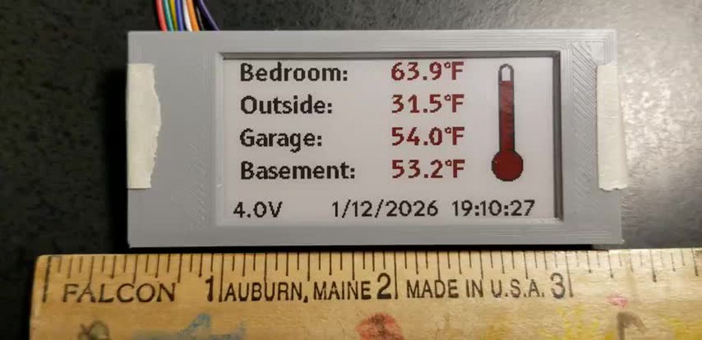 coarse lark
unique patio
https://www.pololu.com/category/136/voltage-regulators has a lot of nice small e...
coarse lark
unique patio
https://www.pololu.com/category/136/voltage-regulators has a lot of nice small e...
maybe i should have read this earlier, i spent yesterday's afternoon making this. i'll keep these in mind for future projects.
i scaled down to only 2 servos (my goal is to make a simple robot car with a claw/grabber so 2 servos is enough), i chose the AP63205 because it needs few external components.
It's a 2A step down which should be enough for this project (SG90 servos have a ~650mA stall current so 1300mA for 2 servos + say 300mA for an ESP32S3 with wifi enabled and some sensors, total ~1600mA).
it was hard to choose a power chip because most either couldnt supply enough current or needed more than 10 components to work (i am working with a limited budget rn, a lot are in QFN packages which i dont feel ready to work with).
now im looking into a mosfet for reverse polarity protection on VIN (something with a drain current > 10A, my current candidate is the AO4407)

 jovial yew
So I'm working on a small project with some very tight tolerances, and I initially had the button attached with wires, but I plan to make quite a few of these, and the wires are not the easiest thing to do. So I'm currently considering an edge-to-edge connection, like in the 3rd pic, but I'm not too sure how to execute it. Does anyone have any suggestions on how to make sure it will fit, or any other suggestions of how to eliminate the wires and make it easier to assemble? Through hole pins won't work since there's a surface mount device on the other side.


 jade wedge
Quick questions about USB C charging. I'm designing a board that will charge from USB C. Nothing fancy at all, just needs 5v 500mA tops.
Am I reading correct that I want two 5.1k resistors to ground, one on each CC pin on my schematic?
Also, is tying shield to ground appropriate (or at least acceptable)?
 elder peak
Two 5.1k resistors yes. Don't try to use less than two 5.1k resistors; that's a repeated design failure.
Ground to shield is ... complicated. Someone else can correct me but the least bad approach is probably to just leave them floating?
 limber rover

yo is this ready for production?
25 kalih choc v1 key switches
2004 20x4 lcd screen with i2c adapter
adafruit s32-s2 feather
lipo batt 3.7V


 cinder anchor
elder peak
Ground to shield is ... complicated. Someone else can correct me but the least ...
cinder anchor
elder peak
Ground to shield is ... complicated. Someone else can correct me but the least ...
Yes, leave them floating.
cinder anchor
limber rover
yo is this ready for production?
Hard to tell without seeing the diagram.
limber rover
cinder anchor
Hard to tell without seeing the diagram.
you mean the schematic?
cinder anchor
limber rover
you mean the schematic?
Yes.
limber rover
cinder anchor
Yes.
hold up ill bring it up
i kind of didnt do it that much
ill finish up
 jade wedge
elder peak
Ground to shield is ... complicated. Someone else can correct me but the least ...
jade wedge
elder peak
Ground to shield is ... complicated. Someone else can correct me but the least ...
Ok. I just remember trying to figure it out for USB micro, and found pretty much every answer possible. Yes, no, "isn't it obvious", "it doesn't matter", "only if you want everything to explode"
I think eventually I looked at what Adafruit does with their Feather boards, and I think the shield is grounded there.
cinder anchor
limber rover
by production i mean its personal use
I don't see anything immediately wrong with it. Did you add ESD protection?
limber rover
cinder anchor
I don't see anything immediately wrong with it. Did you add ESD protection?
hmm difficult question
do you see some?
i didnt specifically go into that too much
first time i do something like this lol
jovial yew
I hope this is ok to ask here. I just got the first version of this board, and unfortunately the edge-to-board fingers didn't fit in the slots, as the bevel in in the slots was too far out, also, the pad for solder was hitting the top and bottom edges. I updated the design with some measurements I took by eye, but before wasting another 12 dollars on boards, I'd like a second opinion on if it will fit. I use OSHPark if that matters.

 manic magnet
Could anyone judge my digital (on off) automotive input protection schematic? I don't really know what I'm doing 😅
 tulip swift
Looks like your zenor is in backwards? Right now you are clamping the node between R28 and R27 at 0.9V.
Your voltage divider on the input will give you, at that same node, a high of 2.77V if the zenor was turned around.
With the two schottky diodes on the left, is the zenor even needed?
manic magnet
tulip swift
Looks like your zenor is in backwards? Right now you are clamping the node betwe...
It's true, I did some simulations in LTspice. Seems I can raise the 3k and I should reverse the zener
manic magnet
I changed the design and added a pullup/down option with solderable links, any more thoughts?
 tulip swift
manic magnet
I changed the design and added a pullup/down option with solderable links, any m...
tulip swift
manic magnet
I changed the design and added a pullup/down option with solderable links, any m...
What is Vcc? Is it different than 12V and from 3.3V? If it is 5V or 3.3V then if you jumpered to Vcc your 12V input then high will cause a "backwards" current flow of a milliamp or two "up" through R33. What is the intended purpose of either of those jumpers?
manic magnet
tulip swift
What is Vcc? Is it different than 12V and from 3.3V? If it is 5V or 3.3V then if...
VCC is 12V yes. The two jumpers are to select between a "floating" and GND input or a floating and +12V input as both are common in automotive environments. However I do see now that R25 will likely act as a pulldown when R33 is not jumpered
So I don't think I need the Pull-down jumper
tulip swift
manic magnet
VCC is 12V yes. The two jumpers are to select between a "floating" and GND input...
Oh I see. You are anticipating your INPUT_FROM_12V to be coming from an open-collector/drain output of something. I can't imagine you would need to pull down. But having a pull up if needed is fine but not the way you implemented it. As drawn above if you enabled the pull-up for a "high" on the 12V side meaning the output of your sensor/device is open and you are depending on your pull-up, 3V3_GPIO is only going to be about 2V (voltage divider of 14.7k and 3k) which may not be high enough. For example ESP32-S3 I believe only guarantees a high detect if your input is at least 0.75x3.3V = 2.48V.
manic magnet
I see, so the pullup should be after the voltage divider and on the 3v3 rail?
tulip swift
I think you should design the circuit for whatever signal source is on the 12V side. If the 12V "thing" outputs 0 or 12V (push pull configuration) make the circuit a voltage divider. If your 12V "thing" is open collector then you are controlling the voltage to whatup you have it pulled up to and then you only need a pull up resistor on the 3.3V input.
The other thing to be careful of is how your "thing" outputs 12V. If it is a push-pull mosfet kind of thing where one mosfet pulls it to the 12V rail and the other to the 0V rail, then the voltage divider is what you want. On the other hand if it instead uses a pull up resistor inside to 12V and then the output acts as a switch pulling the output low, then you have to factor in the device's own internal pull up with your pull ups. If the thing has a 10k pull-up for example, you again get into the same situation you have above with the 4.7k pull-up on your circuit. The input won't get high enough.
manic magnet
tulip swift
The other thing to be careful of is how your "thing" outputs 12V. If it is a pus...
I see, that's an interesting thought. I didn't think about that. I want to make my board to control as many "things" as I can, so I can't say for sure what it will be. I think I will be best off removing the pullup, not making this so complicated for no reason, and adapting the external wiring to be compatible with this type of input when it comes to it. Thanks for the advice!
tulip swift
You might be able to do it with a simple mosfet circuit. Please excuse my high-tech advanced CAD tool (BIC = basic ink CAD).

Then it doesn't matter if your 12V thing is outputting 12V directly or if it also has an internal pulls up to 12V. Both should work here. Just note that your 3.3V input will be normally high.
tulip swift
manic magnet
I see, that's an interesting thought. I didn't think about that. I want to make ...
☝️ Forgot to use the reply option so see above. Also note that circuit doesn't anticipate any of the normal problems you might see in an automative environment so you will probably want to add basic protections stuff (Transient Voltage Suppressor (TVS), MOVs, etc.) around for voltage spikes, load dumps, and such.
 maiden spear
sorry for reposting, just thought this might be more relevant in this channel.
Hi, I was wondering If anyone had any advice for my project. I am trying to make a custom 4 layer PCB that incorporates GNSS and BLE antennas. I'm driving the Bluetooth Low Energy from an STM32 (STM32WB50CG) and am planning to use a chip antenna. For the GNSS I want to use a Ublox MAX-M10S via a Passive Patch Antenna. I've attached a few schematics and am starting to think about layout, I ideal it need to be quite compact eg. 80 x 35mm ideally (I know ill sacrifice GNSS performance as I dont have a large ground plane but I'm happy to have reduced connection quality as the device will only be used with clear sky view).
Ultimately, I am unsure of the separation that I need between the 2 antennas. Should I have them on opposite sides of my rectangular board? can I place them next to each other (30mm separation)?
edit. If I place them on opposite sides of the board I may end up having the Chip antenna arround 20mm from the USB port. I doubt I would have a problem with 5V line as I can route it far away but would having a large metal SMD device nearby effect the signal
Any help would be appreciated. Many thanks

 unique patio
maiden spear
sorry for reposting, just thought this might be more relevant in this channel.
...
unique patio
maiden spear
sorry for reposting, just thought this might be more relevant in this channel.
...
The BLE transmission may desense the GNSS receiver. The antenna datasheet you linked to says:
The antenna should be placed at the center of the ground plane with a length and width of 70mm.
Maintaining a square symmetric ground plane shape and symmetric environment around the antenna is
critical to maintaining the excellent axial ratio and phase center performance shown in this datasheet.
I would try to keep them as far apart as possible, and of course you want no ground plane under the BLE antenna, assuming it's a trace anntea.
but I have no particular experience with this
maiden spear
Ok! Thank you for your help
manic magnet
tulip swift
You might be able to do it with a simple mosfet circuit. Please excuse my high-t...
I thought about this, it would nicely "isolate" from any voltage spikes and such. I'll look into this a little more
manic magnet
tulip swift
☝️ Forgot to use the reply option so see above. Also note that circuit doesn't a...
I simulated a 60V load dump scenario, eventhough it's an electric car and the 12v should be a lot cleaner than internal combustion. The simulations showed that a 60V input over half a second would result in less than a milliamp flowing through the BAT54 diodes, and the voltage remaining at 3.6V. Maybe adding a TVS is a good idea regardless
 bright fiber
Any chance someone here knows how to edit a part in fritzing? ended up with the wrong version of a part and jsut need to modify hole sizes for the connectors but havent been able to figure out how it works.
 teal zenith
does anyone know any good sources for small rotary switches? i've been digging all over digikey and it seems like every rotary switch is like 1" diameter. I'd really rather have a small one, and i know they exist because i've seen them in parts bins before
actually i may have just found what i was looking for on tayda ... i thought i'd searched them before but it looks like they have some
teal zenith
they have some.. but not sure if they're exactly what i want. i've designed myself into a bit of a corner so my options are limited
unique patio
teal zenith
does anyone know any good sources for small rotary switches? i've been digging a...
They are available but they're expensive. Start looking at $15 and up (e.g. Grayhill, NKK).
what specs are you looking for? Could you use a rotary encoder?
teal zenith
unique patio
They are available but they're expensive. Start looking at $15 and up (e.g. Gray...
an encoder would work too, but basically it's for a cosplay prop and i need a 3-4 way selector switch, old military radio style with more of a toggle lever rather than a knob, but i don't have much space to put it
teal zenith
unique patio
They are available but they're expensive. Start looking at $15 and up (e.g. Gray...
 teal zenith
unique patio
what specs are you looking for? Could you use a rotary encoder?
teal zenith
unique patio
what specs are you looking for? Could you use a rotary encoder?
it may not really be possible, that's right at the edge of the object, the only real way to make it work would be if the switch was like 8mm in diameter which isn't really realistic
unique patio
teal zenith
it may not really be possible, that's right at the edge of the object, the only ...
the smallest ones I can find are 0.5", and they are very expensive. You could maybe hide a gear behind there that controlled a rotary switch in a more spacious location. Or use a slim potentiometer or a rotary encoder
that looks like just two positions, is that right?
teal zenith
yeah, i'm doing a pretty lose adaptation so ii'd prefer 3 or 4 stops
it looks like NKK and grayhill both have some that might work, they're in the $16-$45 range. the list of parts has so many similar options so filtering through it is a bit rough
unique patio
teal zenith
it looks like NKK and grayhill both have some that *might* work, they're in the ...
there are rotary dip switches with shafts that are quite tinybut they have a short life expectancy
if you have more room to the right and above you could make something that moves a larger "blade" behind the panel. Not sure how to make that activate a switch.
does this have to pass current or do you just need to read the position?
you could use a rotary encoder and attach a bar to the shaft that hits against stops so you can't move it more than say 1/4 turn
teal zenith
no current, jsut reading digitally
unique patio
"limited rotation rotary encoder" is the term
but I don't see any that aren't fancy
hencd the idea of attaching something like a pointer to the shaft behind the panel to limit rotation. Or you could do the same on the front: use a pointer knob like above, and add limit stops with studs at the end of the rotation limit
teal zenith
hmm.
unique patio
also there are potentiometers with multiple detents, like: https://www.amazon.com/Multiple-Detents-Linear-Control-Potentiometer/dp/B0CLBGP2YP?th=1
so could read that with an ADC
teal zenith
that is an interesting idea
unique patio
i can't find them on digikey
unique patio
does this have to look like something from a movie or something?
teal zenith
it's concept art from fallout 4
so it's a pip boy but kind of a weird alternate reality version. i already made a great working one based on the fallout 76, so i want to do something different now, and i've never seen someone do the one from concept art, so it looks like something from the radio compartment of a b-17
unique patio
you could also do the detent mechanically with the pointer arm
teal zenith
i don't know if my 3d design skills are good enough for that, i can handle big and chunky pretty well but that kind of fine mechanical dseign is a bit outside my realm
that mechanically detented potentiometer idea is interesting, and nkk has two different options that are close to what i need, it's just actually fitting it into the space i have is difficult
 unique patio
maybe you could use the detent mechanism from a cheap rotary encoder and connect a pot to the shaft
teal zenith
unique patio
maybe you could use the detent mechanism from a cheap rotary encoder and connect...
hmm, something like that could work. i think need to think mroe about how loosely i want to adapt things, because to make everything fit in an actual wearable item involves some pretty big compromises. i'm not a stickler for accuracy, i'm happier with broad-strokes recognizability, lol, so that makes some of it easier
unique patio
good luck! hope this was helpful
unique patio
teal zenith
hmm, something like that could work. i think need to think mroe about how loosel...
teal zenith
unique patio
good luck! hope this was helpful
it was extremely helpful, i didn't know about those brands before, so now i've found a number of options that i didn't have before, and the detented analog pot was something i hadn't ever considered before either
 merry folio
teal zenith
an encoder would work too, but basically it's for a cosplay prop and i need a 3-...
merry folio
teal zenith
an encoder would work too, but basically it's for a cosplay prop and i need a 3-...
Would something like this suffice? https://tech.alpsalpine.com/e/products/detail/EC10E1220501/
It's a quadrature encoder, so the positioning is relative rather than absolute, and that might make selecting a specific setting tricky. On the other hand, it's very compact.
jade wedge
This is reasonable for a USB power bypass, right? This project will charge from USB (VIN here), but also be able to run straight off USB. So the important part is putting a diode between the battery positive terminal, and VIN. Correct?
 unique patio
jade wedge
This is reasonable for a USB power bypass, right? This project will charge from...
unique patio
jade wedge
This is reasonable for a USB power bypass, right? This project will charge from...
but you also don't want to backpower VIN (assuming that's the USB 5VB line), so two diodes to protect both power sources
jade wedge
Ah, good point.
unique patio
you could use a three position switch and switch VIN or battery, with middle position both off. Then you don't need diodes, but the user has to make the power decision.
jade wedge
I think I'll stick with the diodes. I vaguely hope to actually make a product out of this, so I want it to be simple. It's bad enough (to me) that I have a jumper to pick between 100 and 500mA charging speeds.
Also, I was looking at the Feather boards for a bit of guidance on designing this. Is the only reason for a schottky diode the lower forward voltage?
unique patio
jade wedge
Also, I was looking at the Feather boards for a bit of guidance on designing thi...
yes, and also note the Feathers specifically don't support external non-USB 5v power or external 3.3V power. https://learn.adafruit.com/adafruit-feather-rp2040-pico/power-management especially last section
jade wedge
Ok. It makes sense. A basic silicon diode has a drop of about 0.7V, which is a lot when you're talking about potentially only 3.7 to start with.
Ohh... Also I see the feather is fancier and uses a transistor or mosfet to entirely disconnect the battery while it's plugged in.
This is why I really appreciate the availability of schematics.
I think I'll just go with a dual diode package though. Simple for me.
Yessss... There we go.

 marble gazelle
jade wedge
marble gazelle
jade wedge
Yeah, since the schematic is really only for my purposes, I wasn't worried too much about getting the exact correct symbol.
But more importantly, as danh pointed out, two diodes, one for each source.
Now to shove it in... somewhere.
I can make room. It's not a problem.

 autumn snow
Howdy y'all, I'm creating a custom board design with a charlieplexed LED array driven by the same IS31FL3731 driver IC as the CharlieWing (and other products) and want to make sure that my array is compatible with the companion Adafruit GFX arduino library.
The library implementation suggests that the desired width and height of the led display can be specified. There seems to be some hardware-specific stuff in the library's drawPixel logic, at least for the 16x9 driver breakout.
I intend on going from the 15x7 and 16x9 matrix sizes in Adafruit designs to the 96 LED matrix size (12x8) seen on the Arduino R4 and recent UNO variants.
My thought process so far is as follows.
The CharlieWing appears to use CA1 through CA9 and CB1 through CB8 for 105 LEDs.
Generally in charlieplexing, the use of n=11 tristate IO means n^2 - n = 110 LEDs, with the driver IC at n=9 per block means 72 LEDs per block as confirmed in the driver IC datasheet.
On paper then 72 of the 105 LEDs are charlie-plexed on block A and then block B is used at n=8 for 56, which makes me believe there are 105/128 addressable with 23 unmounted LEDs in the mapping.
I imagine I can start by physically 'unmounting' 9 already addressable within the 15x7 CharlieWing instantiation and running guess-and-check.
But ideally I can make a 12x8 matrix directly. Could this size let me cut down on the use of block B on the IC, with 96/114 (18 unmounted LEDs) or am I just going from 23 unmounted to 32 if I want to continue using Adafruit's library?
jade wedge
Before I send this off for manufacturing, does anyone see any egregious problems with this design? There is stuff further off to the left, but it's part of an existing design that I've already built, so I'm not concerned about that. I'm mostly checking on the charging (upper half) and boost (lower half) sections.


 spiral pagoda
jade wedge
Before I send this off for manufacturing, does anyone see any egregious problems...
spiral pagoda
jade wedge
Before I send this off for manufacturing, does anyone see any egregious problems...
What's with the ground plane? Don't you want the mounting pins grounded?
jade wedge
For the USB socket I have not been able to figure out if I should, shouldn't, or it doesn't matter.
For the switch, I just didn't think to.
spiral pagoda
I'm assuming you're ok with no mounting holes and minimal indication LEDs
Maybe you're right that it doesn't matter if the USB or switch are grounded. It just struck me as odd
jade wedge
Yeah. The board is for driving LEDs, so a power indicator seems redundant. Also I don't really have an enclosure design as it's intended to be a very general purpose design for costumes and props.
spiral pagoda
Are you planning on soldering to those pads on the back side of the battery JST connector?
They're a bit big for test points, but the ground might be tricky to solder to with its solid connection
jade wedge
Pads are for if someone buys one, and decides to get a battery that doesn't have a plug.
spiral pagoda
Ok. Consider thermal relief on those pads
jade wedge
Will do.
jade wedge
No more than 500mA. That's the rating of the diodes. Tracks are big enough. The 5V one in particular is way oversized.
spiral pagoda
Also, consider a DNP capacitor in parallel with R8 in case you need to improve the responsiveness of U3
0603 is fine
One more thing - J1 should tie to the ground of C3 and C4 on the top layer rather than forcing everything through that little via
jade wedge
Would bringing it up to the ground of J1 be sufficient?
spiral pagoda
I'm not sure what you mean
jade wedge
Oh, wait, that's what you said.
spiral pagoda
Did you put your name/date/version on the back silkscreen?
jade wedge
I've got my name on it, but adding more would be easy.
spiral pagoda
Nice work!
Now a design question rather than layout: Have you considered what you want to happen when the lipo is drained?
jade wedge
Thank you.
And thank you for taking the time to give it a look. I will definitely see about adding thermal reliefs for the battery pad, and the extra cap to go with R8. I've already added a new track to go from C3 ground to J1 ground
spiral pagoda
It looks like TPS61023 can operate down to 0.5V, but drawing your lipo below 2.5V (or even 3V) can really damage it
jade wedge
I'll be using batteries with protection built into them, and suggesting that when someone is picking a battery that they should do the same.
spiral pagoda
Ok. Cool that this could even operate off a rechargable AA
Not with the charging circuit, of course
but low-voltage boosts are kinda rare
jade wedge
I was going to make another design that was intended to work off AA batteries, but I hadn't thought of just not populating the charging circuit.
I suppose that does make it way easier.
spiral pagoda
Yeah. You could even make a bypass for D2
jade wedge
Slap a 0ohm resistor across it and call it a day.
spiral pagoda
On the diagonal, yeah
jade wedge
Awesome. Well, again, thank you for your time and input. This makes me much more confident moving forward. Will I actually be able to do all this SMD work without breaking anything? Time will tell.
spiral pagoda
Honestly, a hot plate works wonders for SMT soldering, especially since you have everything already on one side
Ideally a small one with good temperature control, but it's not that critical
jade wedge
Right now it'll be a hot air gun, and regular iron for touching things up. The previous revision used a USB micro port, and I managed to do that. U3 is about the same size, but more exposed.
latent jungle
I call that the “surface tension tap”
 fervent arrow
This is a really specfic part I'm having issues with, but if someone could give me some advice or ideas I would love them forever.
I have a protoboard with a HT8950 voice modulator 18-pin IC chip. The LAMP pin constantly lights my led, which is only supposed to happen when it gets input from a mic, but it does it even when theres nothing actually connected to the audio in pin?
spiral pagoda
fervent arrow
This is a really specfic part I'm having issues with, but if someone could give ...
If the pin is floating it could be picking up radio signals or radiation from AC wiring. Try a pull-down to keep it steady
The example schematics all show a 33k resistor from AI to AO which is probably to provide bias but might be enough to reduce the erroneous input
 velvet steeple
Does anyone have experience with water pumps, hose, and mister heads for terrariums/vivariums? I'm trying to figure out a hardware design to be controlled with a microcontroller and a humidity/temperature sensor. I already have a Qt Py ESP32-S3 with the sensor logging data via MQTT. I just need to know where to go from here to actually have it mist the environment when humidity dips below a specific threshold. Can I do it with a Qt Py or do I need to upgrade to a feather or rasppi?
spiral pagoda
The QT Py should do just fine
Your mister requires a certain pressure and flow to operate. Make sure you choose a pump that provides that, and think about where the pump will be getting power from
The absolute simplest method to control a DC pump is a low-side MOSFET, but you may actually prefer the flexibility of a SSR.
Looks like giant African millipedes prefer 70-80% humidity and 72-78F. Sounds like a humidor. Except cigars tend to mold above 75%
velvet steeple
spiral pagoda
Looks like giant African millipedes prefer 70-80% humidity and 72-78F. Sounds li...
I started with a fogger. It kept the air humid but not the substrate, which needs moisture for things to rot as they are detrivores. Too much moisture in the substrate = bad, not enough = bad.
spiral pagoda
A mister makes sense then. Will you have this connected to your house water or are you going to pump from a reservoir?
velvet steeple
spiral pagoda
A mister makes sense then. Will you have this connected to your house water or a...
A bucket or container of some sort holding distilled water
spiral pagoda
Many garden misters expect 30psi
velvet steeple
it will be lower than the tank too...
velvet steeple
We would need to minimize dribble as much as possible. None is ideal
spiral pagoda
Got it. Then high pressure is needed. Aquarium pump (impeller) will not suffice
Parastaltic?
Or maybe a vane pump?
A piston pump will cause bursts of water which might be noisy and frightening to the millipede
Could dampen with an air accumulator of course, though that will take some tinkering to get right since we don’t know the dynamics of the system
velvet steeple
I'm honestly googling most of the things you are saying 😄
spiral pagoda
But if those are too expensive, you could DIY it with a soap dispenser and a RC servo
How much water do you want to dispense at a time?
velvet steeple
spiral pagoda
How much water do you want to dispense at a time?
Just enough to nicely dampen the top layer of substrate. I'll probably need to have 2 heads, one for each side. 29 gallon tank. 30.19" W x 12.4" D x 20.86" H. I have about 6-8 inches of substrate
spiral pagoda
I don’t know the calculation for that, sorry
Are you talking about a cup? A tablespoon?
Right now you’re spritzing by hand with a spray bottle, yeah?
How many spritzes does it take? Do the same amount into a measuring cup and see how much it is
velvet steeple
I'm still dialing that in with my daughters spray bottle for her hair 😄
I think I found a path forward with a MOSFET and a 12v diaphragm pump that does 80 PSI
spiral pagoda
Nice! A diaphragm pump will still produce some pulsing, but hopefully less than a piston pump
Millipedes are sensitive to vibrations, aren't they?
And don't forget the flyback diode
velvet steeple
Yeah but we are talking twice a day.
spiral pagoda
cool
velvet steeple
spiral pagoda
cool
The pump is 12v 3 amp. I got a IRLZ44N MOSFET (47A 55v), IN5404 diode (3A 400V), a 12V 5 amp power supply, and a 12v to 5v 3 amp buck converter to power the qt py. Does this sound solid?
spiral pagoda
Great choice of MOSFET but you'll want a schottky diode
1N5822?
Honestly you could use a 1N5817 and it would be fine
velvet steeple
what is the concern here?
spiral pagoda
The concern is switching speed. The MOSFET has a maxium voltage above which it will arc internally and fail. When you shut off the pump, it temporarily acts as an inductor and wants to keep the current flowing
The diode provides a path for this, which is why you ned a diode that switches very quickly
Otherwise the high current with nowhere to go will translate into high voltage and hurt your mosfet
velvet steeple
and you're saying the 5822 switches faster than the 5817?
spiral pagoda
I'm saying they both switch faster than the IN5404
velvet steeple
I appreciate your help thanks. We'll see how this goes
velvet steeple

Transform your outdoor space with these premium 360-degree adjustable copper misting nozzles. Crafted from durable copper, these versatile sprayers deliver precise water distribution for various applications. The fully adjustable design allows you to customize the spray pattern and coverage area ...
I'll probably just need to chain 2 of these together and I have holes that they can slide into
I'm already thinking about ways to adapt this to our rain barrels and using it to water our garden
spiral pagoda
Nice choice
 worn iris
 any UPS recommendations with li-ion bat connector for a PI? perferrable one without the big 18650 battery holders
designing my cm4 carrier board rn and don't trust myself quite enough to do managment stuff with li-ion, would have just nabbed a geekworm one since those ar rated 5v 5A but they don't seem to offer schematics or anything aside from a dxf image where nothing is labelled except the silkscreen text for the website and the product name/rev
pastel night
i made my own but did you see this: https://www.adafruit.com/product/5705

Witty Pi is an add-on board that adds real time clock and power management to your Raspberry Pi. It can define your Raspberry Pi’s ON/OFF sequence and significantly reduce energy ...
p.s. you don't need 5Amps... unless you doing a pi5?
there are others similar.
worn iris
unfortunately there is none in stock, like at all 


so not in stock on those 2 sites but across the pond theres a few sites that do have them in stock i just gotta wait a bit longer
pastel night
any of the pass thru power banks are also an option... https://www.adafruit.com/product/4288 but... 1) keep the output cable short, 2) if rpi 4 or 5 use one with a 3 amp output rating.

Here's a hand-held-size rechargeable battery pack for your Raspberry Pi (or Metro, or anything else that uses 5V!). This pack is intended for providing a lot of power ...
it's a "dumb" solution but is "off the shelf".
 smoky terrace
question for folks who've worked with the Black Acrylic diffusion panels, how well do they laser cut? (https://www.adafruit.com/product/4749 for reference)
nice whoppin' rectangular slab of some lovely black acrylic to add some extra diffusion to your LED Matrix project. This material is 2.6mm (0.1") thick and is made of special ...
I've got some isolinear optical chips I made out of neon acrylic and I want to use the black difusion acrylic to make something that looks Star Trekish to slot them into
jovial yew
I'm looking into making an EM radiation sensor with an ESP32 for non-ionizing radiation like Wifi, Radio, power lines, and to a certain extent people. I want it to be as sensitive as possible, so pretty much always detecting, I don't really care about accuracy or precision so fluctuation is fine. Could I use a TL072? I've seen lots of projects online, but a lot of them use higher power like 5V or 9V, or don't use a microcontroller.
spiral pagoda
I would recommend a log amp, though they run about $20 each
spiral pagoda
jovial yew
spiral pagoda
I would recommend a log amp, though they run about $20 each
Interesting, pretty pricey, but I'll look into it, thanks for the suggestion.
 vestal iris
smoky terrace
question for folks who've worked with the Black Acrylic diffusion panels, how we...
vestal iris
smoky terrace
question for folks who've worked with the Black Acrylic diffusion panels, how we...
I had the black acrylic laser cut from a sign shop here and it worked great.
 smoky terrace
Awesome, I'm thinking of using it for an LCARS display for isolinear chips
 vapid lark
is there anyone in here who can help me check over my entire sheet? i THINK i am done! but i've been working on it for hours and days and my eyes are tired! PM me and i'll send a screenshot of it (i am using easyEDA software btw)
latent jungle
vapid lark
is there anyone in here who can help me check over my entire sheet? i THINK i am...
don’t ask to ask, and most people prefer a public review to avoid wasting time suggesting things
spiral pagoda
vapid lark
is there anyone in here who can help me check over my entire sheet? i THINK i am...
We can make a thread if you’re worried about cluttering the channel
 muted skiff
Would anyone be able to help me diagnose why my USB Power Override section (right-side) does not work as intended? I've simulated the section using Falstad and the logic seems to check out. I essentially want to cut off VBUS whenever I have a barrel connector plugged in (12V to 5V buck on top side).
I've confirmed both power inputs work independently from one another on my PCB but when I add the DMP2045U, VBUS does not make it to VDC no matter what the power state of the buck is.
 spiral pagoda
muted skiff
Would anyone be able to help me diagnose why my USB Power Override section (righ...
spiral pagoda
muted skiff
Would anyone be able to help me diagnose why my USB Power Override section (righ...
At minimum, Vbus should conduct through the body diode of Q1. Check the forward voltage with a multimeter to make sure it’s installed correctly.
Also check continuity from the USB port to Vbus. Did you make sure to solder closed JP13 and JP18?
muted skiff
Alright I've tested the continuity and it seems like the footprint was the issue. The standard SOT23 on KiCad has a different pin numbering than the DMP2045U datasheet expects. Woops. Thanks!
latent jungle
muted skiff
Alright I've tested the continuity and it seems like the footprint was the issue...
Not sure where you got the symbol, but for discrete parts like FETs, I prefer to use the KiCad's default parts that list the pin order in the symbol name:
It makes matching the symbol pinout to the footprint much easier.
 muted skiff
Neat, thanks! I just used the PMOS symbol from the Simulation_Spice library. This seems a lot clearer.
latent jungle
I wouldn't use the Spice symbols for anything but simulation.
In this case, you wanted Q_PMOS_GSD

 muted skiff
Gotcha yeah that's the one haha
spiral pagoda
You might consider accounting for the voltage drop of D11 in your buck regulator output: put the feedback resistors after D11
 quasi flare
anyone know how many amps the "5V" line on a feather can supply? (up to the max for the USB connection, obviously)
spiral pagoda
quasi flare
anyone know how many amps the "5V" line on a feather can supply? (up to the max ...
500mA, limited by the MBR0540 diode
quasi flare
dang. need 1A. guess i'm gonna have to split the usb cable before it gets there.
quasi flare
i don't think so, haven't looked at the schematic recently.
was more like can the traces handle 1A. 🙂
spiral pagoda
Yeah, I think they’ll be fine
quasi flare
building a thing to turn a wyze cam on and off depending on data from google calendar. so need 5V1A to go through a SSR to power the cam.
spiral pagoda
Expect a significant voltage drop though from the USB cable. You’ll probably only get 4.6V at 1A
spiral pagoda
Is this 1A continuous or intermittent?
quasi flare
not sure. specs just say 5V1A.
might be worth splitting the power pre-feather so it doesn't overheat.
spiral pagoda
Apparently a 10 mil 1oz trace will only heat up by 11C with 1A continuous
But I didn’t actually measure the trace
 fierce elk
Is it necessary to use a P-FET circuit to safely disconnect a lipo battery from a microcontroller (like this https://www.adafruit.com/product/1400), or can you just hook up a switch in series with the battery terminals?
I've done the latter in the past and it was fine but I'm not too sure how dangerous that is
unique patio
fierce elk
I've done the latter in the past and it was fine but I'm not too sure how danger...
a switch is fine, and is straightforward
fierce elk
unique patio
a switch is fine, and is straightforward
Gotcha, thanks!
pastel night
most batt potection circuits are N-Fet (low side).... P-Fet is high side. There are reason either. A contact type switch is also an option on either high or low side. however micro controllers rarely have fingers (that can push switches).
 marsh bear
eInk Feather friend users - does the FPC connector "open", or is it simply an insertion connection. I have an extension cable coming tomorrow and don't want to mess things up!
Thanks!
wintry wind
My two had two fingers that you slide out (not up) trying to get them equal and then slide the cable in and push the two fingers back in to tighten down the cable.
tulip swift
marsh bear
eInk Feather friend users - does the FPC connector "open", or is it simply an in...
You need to gently slide out the retainer clip before insertion (the grey parts) then reverse when you get the cable seated)...
 wintry wind
tulip swift
wintry wind
tulip swift
Much better -- picture and arrows worth a thousand words!
tulip swift
wintry wind
Much better -- picture and arrows worth a thousand words!
I should add that the dark grey part will only slide out a couple/few mm so basically just pops outward a bit (don't try to pull it further than where it stops normally), slide in your cable, push the dark grey clip back to the left to secure.
 frosty parcel
hey! could anyone help me troubleshoot a switching mode power supply issue?? I am using the linked 1Mhz IC to step 12V down to 5V and built the typical application schematic as shown in the data sheet but for some reason it's getting quite hot and the output looks like this.
https://www.mouser.com/ProductDetail/Diodes-Incorporated/AP63205WU-7?qs=u16ybLDytRZtkj8PzdWCOw%3D%3D

<@&741361254035095602> <@&617066238840930324>
 distant raven
I’d have to see a schematic and probably a picture of the board to make any guesses
latent jungle
frosty parcel
share your PCB design
frosty parcel
well, it's on a breadboard
and it's.... not exactly clean, it's a huge switching loop but there's no current being pulled (it's just 12v in and going directly into the scope)
 worldly schooner
frosty parcel
and it's.... not exactly clean, it's a huge switching loop but there's no curren...
worldly schooner
frosty parcel
and it's.... not exactly clean, it's a huge switching loop but there's no curren...
Are your 2x22uF caps in series or parallel? Breadboard is very hard to follow when components are placed tightly.
frosty parcel
worldly schooner
Are your 2x22uF caps in series or parallel? Breadboard is very hard to follow wh...
parallel
worldly schooner
If you put a dummy load across the output, does the scope output change?
frosty parcel
yea sorry abt that
latent jungle
Your breadboard is the problem.
SMPS and breadboards don’t mix.
There’s a reason the data sheets include a detailed PCB layout with ground planes and incredible short traces.
frosty parcel
latent jungle
Your breadboard is the problem.
so u think i should just order a pcb w/o prototyping it?
worldly schooner
If you want to prototype it, you’ll have to get a bit artistic with soldered connections.
And given the thermal callouts, active cooling is encouraged.
latent jungle
frosty parcel
so u think i should just order a pcb w/o prototyping it?
You can’t (properly) prototype a SMPS without a PCB.
Especially if it is switching at 1 MHz
worldly schooner
I’d advise using a PCB to prototype it, or remaining extremely faithful to the app notes and send it straight into your design.
I’m tempted to try 3D assembly of an SMPS power supply for fun, but yeah there’s more that could go wrong than right
frosty parcel
worldly schooner
I’m tempted to try 3D assembly of an SMPS power supply for fun, but yeah there’s...
yea... especially since you saw what happpened when i tried to hand solder this tiny ic to a pcb
worldly schooner
@latent jungle any SMPS suggestions for a fun challenge? I’m thinking through-hole components only and tying the output to a DC fan to cool itself as a nerdy little art piece.
latent jungle
Sorry, no. I don’t find solving SMPS design challenges as fun.
frosty parcel
latent jungle
Sorry, no. I don’t find solving SMPS design challenges as fun.
ok ig ill just order a PCB and pray i did it correctly
if i did do it corectly should it really require active cooling tho?? or just proper pcb design
latent jungle
cooling requirements depend on your application
spiral pagoda
worldly schooner
<@312943079160283137> any SMPS suggestions for a fun challenge? I’m thinking thr...
If you’re doing through-hole you’ll want to stay 100kHz or lower. But rather than using the new current-mode synchronous buck regulators, you might have more fun with an 8-bit microcontroller operating a boost converter (low-side switch) to drive a string of LEDs or some EL wire. You can even control with a 555 timer if you’re ok with open loop.
I’m actually considering a PIC16F15213 for such a design, because the TPS923650 I had selected was too small to reliably solder
And the PIC is cheaper than a ATTINY85
fierce elk
Anyone know why this would be the output of the ov5640 camera module? Using the test code given from adafruit. It's definitely getting some data from the camera sensor because it darkens when I put my fingers over the lens. MC is the rp2350, using the data pins coming from the HSTX connector (not sure if that's a problem). Only other nonstandard thing I did is I'm using the internal 24MHZ clock generator, so the XC pin is left unconnected

(ignore the small image, running at 96x96 for the sake of framerate)
fierce elk
fierce elk
Anyone know why this would be the output of the ov5640 camera module? Using the ...
Did some more investigating on this - my initial thought was that the 24MHz internal clock on the camera module was too noisy or not good enough. Checking it with a scope, the clock frequency is fine, but should the waveform be more of a square wave? The pixel clock looks very similar (more sine than square wave)
 latent jungle
fierce elk
Did some more investigating on this - my initial thought was that the 24MHz inte...
latent jungle
fierce elk
Did some more investigating on this - my initial thought was that the 24MHz inte...
where are you measuring and how?
fierce elk
latent jungle
where are you measuring and how?
Measuring directly at the output of the clock generator (which goes directly to the XCLK pin on the camera module) via a small jumper wire soldered on. Coupled the scope probe to the same ground as the camera module
The other signals like the href and vsync are very solid square waves so I don't think it's an issue with my measurements
latent jungle
If you’re measuring with a 10:1 probe switched into the 1 position, that would explain the wave shape.
fierce elk
Ohhh I didn't even consider that, hold on
Setting it to 10X this is the new waveform. Still not great

Can definitely see the peaks and valleys of what should be a square wave, so it's definitely better
knotty tiger
fierce elk
Measuring directly at the output of the clock generator (which goes directly to ...
can you show a photo of this test setup, including the soldered jumper wire?
fierce elk
knotty tiger
can you show a photo of this test setup, including the soldered jumper wire?


Part of me is wondering if the messed up video is due to the fact that I'm using the HSTX breakout for the camera data, which would be very unfortunate if that's the case since I need consecutive data pins
knotty tiger
fierce elk
yeah, that’s marginal for accurately measuring 24MHz waveforms. you need better grounding and shielding
latent jungle
fierce elk
Setting it to 10X this is the new waveform. Still not great
1X has less than 10 MHz of bandwidth.
That waveform, in 10X, can be from how you’re connected to ground.
those long wires explain the ringing.
fierce elk
latent jungle
those long wires explain the ringing.
As long as the clock's shape on the scope is more due to the way I'm measuring than the clock itself I'm okay to rule it out for now. Do you think that the wire lengths from the HSTX connector on the feather to the camera module could be causing the messed up image?
knotty tiger
taking off the hook clip and using the needle point of the probe will help. most probes have a ground ring right behind the needle that you can wrap a small ground probe wire around
latent jungle
fierce elk
As long as the clock's shape on the scope is more due to the way I'm measuring t...
breadboards and long jumper wires are not appropriate for signals running in the 10s of Megahertz.
fierce elk
latent jungle
breadboards and long jumper wires are not appropriate for signals running in the...
Yeah this is very much temporary, just trying to get a handle on how it works for now before I do anything permanent. If it's a showstopper to use a breadboard at all then I'll have to bite the bullet and install it on some perf board, but I'll have to deal with that FPC connector no matter what since that's the only way I can interface with those GPIO on this board
knotty tiger
is the FPC on the breakout the same pinout as on the camera module?
fierce elk
knotty tiger
is the FPC on the breakout the same pinout as on the camera module?
No unfortunately, FPC goes from the RP2350 HSTX connector to an HSTX breakout, which then connects to the camera module breakout
The camera requires 8 sequential gpio pins which this board doesn't have (unused) sadly, unless you pull from the HSTX connector
knotty tiger
fierce elk
No unfortunately, FPC goes from the RP2350 HSTX connector to an HSTX breakout, w...
can you highlight the routing of your clock wire? you might be able to get away with it if you run it in a twisted pair with a ground wire the whole way
fierce elk
Which clock, the pixel clock or the i2c clock?
knotty tiger
fierce elk
Which clock, the pixel clock or the i2c clock?
pixel clock. that’s the fast one you have to worry about
fierce elk
It stretches all the way across the board, definitely not ideal... I can try to twist it with a ground wire later today and see what happens. That one doesn't go through the FPC, it goes directly to the microcontroller via a jumper
spiral pagoda
fierce elk
You made an inductor out of the loop of your probe wire and ground lead. Try the spring clip next time
frosty parcel
any chance you could give me some feedback on this pcb design? it's one of my first ones and it's for a 1Mhz buck, esp32, and motor driver


<@&741361254035095602>
 silk lark
why?
 spiral pagoda
frosty parcel
any chance you could give me some feedback on this pcb design? it's one of my fi...
spiral pagoda
frosty parcel
any chance you could give me some feedback on this pcb design? it's one of my fi...
There’s a lot of issues. Start with the layout around the buck regulator. AP63205 is a great chip but you need to keep your inductor loop tight. There’s a recommended layout near the end of the datasheet - try to emulate that
Increase your trace widths for durability and current handling. I usually do 10mil traces unless I need to fit in tight spaces, but you might need more for the regulator. KiCAD has a nice trace width calculator that can help you decide.
Please pick a smaller inductor, too. That through-hole part is enormous and will be the heaviest and tallest thing on your board. Actually the main benefit of using a 1MHz buck regulator is that you can use a physically smaller inductor, saving weight and cost.
What really puzzles me is all those resistors between the ESP32 and motor driver. Are you expecting them to serve as a kind of level shifter?
frosty parcel
spiral pagoda
Please pick a smaller inductor, too. That through-hole part is enormous and will...
i kinda already ordered it and have it so that’s the only one i can use
frosty parcel
spiral pagoda
What really puzzles me is all those resistors between the ESP32 and motor driver...
no, they’re just from the application schematic
i can check what they do rq


ill take a look at the recomended layout and trace width tho, that's a good point
do u think i need to increase all the traces or just the ones that'll be driving the motor and stuff
spiral pagoda
Increase all the traces to 10mil and then adjust as needed
frosty parcel
spiral pagoda
Increase all the traces to 10mil and then adjust as needed
is there a good way to change them all at once in kicad or is that more of a thing i do to each track individually
spiral pagoda
frosty parcel
is there a good way to change them all at once in kicad or is that more of a thi...
I think there’s a way? But you’ll be rerouting a lot of this stuff, so better to set your default netclass
If you programmatically changed all the trace widths without moving them, it would result in a lot of shorts and DRC errors
frosty parcel
spiral pagoda
I think there’s a way? But you’ll be rerouting a lot of this stuff, so better to...
this seem like a more reasonable current loop?
 spiral pagoda
frosty parcel
spiral pagoda
frosty parcel
Pin 5 is a sense pin. The current loop is actually through C3 and C4. So you need the ground of those capacitors to be near the ground of U1, but the 5V on those capacitors to be near the 5V of L1
Here's a great tutorial on this https://www.powerelectronicsnews.com/power-supply-design-tutorial/
frosty parcel
aah makes senes
also for some reason it seems like some of the traces on the blue side are cutting the ground plane on the red side and im not sure why

any ideas
frosty parcel
spiral pagoda
Pin 5 is a sense pin. The current loop is actually through C3 and C4. So you nee...
wait arent C3 and C4 just the Vin and GND pins?
`oh nvm ic what u mean
wait but C3 and C4 are just the output bulk caps for smoothing right
spiral pagoda
frosty parcel
wait but C3 and C4 are just the output bulk caps for smoothing right
I guess we need to talk about what kind of capacitors they are. Did you pick MLCC? Are they still capacitive at 1MHz?
frosty parcel
spiral pagoda
frosty parcel
im using these https://www.digikey.com/en/products/detail/kemet/C1206C226M9PACTU...
Datasheet have the impedance curve, but it's MLCC so probably ok for 1MHz.
frosty parcel
spiral pagoda
I guess we need to talk about what kind of capacitors they are. Did you pick ML...
ok cool
marsh bear
tulip swift
You need to gently slide out the retainer clip before insertion (the grey parts)...
thank you!
frosty parcel
spiral pagoda
I guess we need to talk about what kind of capacitors they are. Did you pick ML...
so basically, should i swap C1 and C2's locations with C3 and C4 and then bring them closer to the gnd
spiral pagoda
The hbridge also has important layout and heat sinking requirements. See pg 23 of that datasheet
I think you will need more space to work with. An easy way to get this is to flip your through-hole components to the bottom side
Anyway. Read that tutorial. It's very helpful
spiral pagoda
@silk lark Have you ever seen series resistors on the inputs for an hbridge? They’re in the datasheet but not clearly explained. Inputs are 3.3V compatible but 20kHz max
frosty parcel
i mean i’d breadboarded w them and it worked fine
silk lark
spiral pagoda
<@351136009922019331> Have you ever seen series resistors on the inputs for an h...
I've seen that on inputs for hobby servos. Presumably to protect the pins?
inside the chip it's mosfets, so maybe to limit the base current?
spiral pagoda
Mosfets don't have base current. The gate is a capacitor
I thought maybe it was to reduce slew rate? But at 20kHz I don't see why it would matter
silk lark
perhaps a precaution for very delicate old microcontrollers?
frosty parcel
also im a lil confused here for the buck

like there isn't any resistor in the application schematic so like... what are R1 and R2?
i just have mine set up like this
 frosty parcel
spiral pagoda
Mosfets don't have base current. The gate is a capacitor
frosty parcel
spiral pagoda
Mosfets don't have base current. The gate is a capacitor
should i just ignore the resistors
also not clear on what C4 is
knotty tiger
frosty parcel
should i just ignore the resistors
where's the datasheet for the switcher?
spiral pagoda
frosty parcel
like there isn't any resistor in the application schematic so like... what are R...
Those are to move the poles on the frequency response, improving step load response and stability. Basically the capacitor advances the feedback so the regulator responds to droop before it gets very far
knotty tiger
frosty parcel
should i just ignore the resistors
they're probably a filter for the feedback node, but you need to see what the datasheet says about them
spiral pagoda
knotty tiger
where's the datasheet for the switcher?
knotty tiger
spiral pagoda
https://www.diodes.com/assets/Datasheets/AP63200-AP63201-AP63203-AP63205.pdf
which particular chip are you using? the fixed-output ones seem to not need the filter. the variable-output ones need a resistive divider, with the capacitor to adjust the frequency response
spiral pagoda
They're using the 5V one. You're right that the chip works fine without the filter. I usually add it anyway and haven't bothered to compare.
frosty parcel
ok sounds good so ill just ignore those
spiral pagoda
I mean... how much do you want to learn about buck regulators? You could always leave the footprints in and not populate
But if you leave the footprints out, it's sure hard to fit an 0805 onto that sot23-6
frosty parcel
i mean id like to learn about htem
i thought i didnt need that filter since im just using it at 5v tho
i might be misunderstanding what you're saying
id need to populate tho or else FB wouldnt be connected to VOUT
unless i also bypassed the footprints
spiral pagoda
You probably don't need the filter, but we don't know for sure.
frosty parcel
i mean, when i breadboarded it it seemed to work fine w/o the filter
knotty tiger
Figure 20 shows the application circuit for the variable-output versions, which does have the filter and the resistive divider. you probably don't want a divider if you're using the fixed output voltage
frosty parcel
no worries
do u think i could get away with just beefing up the traces that'll actually be carrying substantial amounts of power and leaving the IO ones as is?
spiral pagoda
Are you particularly against redoing your whole layout?
There's a lot to be improved
frosty parcel
i mean not really
lemme make a quick list of the things to change:
- increase general trace width to 10mil
- substantially increase power carrying
- use buck and motor driver layouts from data sheets and make a power loop on the buck
is that about it?
or are there other big things

this is where im currently at
btw red is a GND plane and blue is a 12v plane
spiral pagoda
No, there's a lot more
frosty parcel
oh ok
spiral pagoda
All those vias and routing bends around R1-R6 are curious. Why is the layout like that?
frosty parcel
i was trying to do it to keep the ground plane solid
spiral pagoda
Or D1 and R7. Why go to the bottom layer rather than repositioning your components?
While I'm routing traces, I often find that I can make a trivial change to the layout (or even the schematic) that makes routing cleaner
In this case, I wonder if you could remove R1-R6 entirely?
frosty parcel
do you think i should instead just use two ground planes so i dont have to worry about breaking it when routing on top
and then just carry the +12v in traces
spiral pagoda
What do you mean "two ground planes"?
frosty parcel
ground plane on top ground plane on bototm
ig "filled zone"
idk what the proper terminology is
spiral pagoda
But you also have traces on those layers
You could stitch them together. Better if you can minimize the traces on the bottom
You'll need it not just for current carrying but also for heat
frosty parcel
oh ok
spiral pagoda
How much current can your motor take?
frosty parcel
i think it's 5.5A stall
but it shouldnt get anywhere near that since the gearbox cant handle it
i can send link
spiral pagoda
The gearbox breaks if you stall your motor??
frosty parcel

This gearmotor consists of a high-power, 12 V brushed DC motor combined with a 98.78:1 metal spur gearbox. The gearmotor is cylindrical, with a diameter just under 25 mm, and the D-shaped output shaft is 4 mm in diameter and extends 12.5 mm from the face plate of the gearbox. This gearmotor is also available with an integrated encoder.
Key...
note 2 basically explains it

so it's recomending operation at about 1.25A
even though stall is 5A
spiral pagoda
Yeah, DC motors don't like to stall. But they always start from stall
frosty parcel
oh so on startup i would actually be pulling 5A?
spiral pagoda
Ok. So your hbridge traces need to handle at least 1.25A, but ideally 5A
Yeah, for a fraction of a second. What's it turning?
frosty parcel
it's turning a wheel that's pulling the cord on some window blinds lol
spiral pagoda
Ok. Did try it and see how much current it actually needs?
Most benchtop power supplies will tell you, or an ammeter
frosty parcel
havent tested yet but i checked the force required and it should be about 25% of the stall current
maybe a lil less once it starts moving
spiral pagoda
Ok
Torque is proportional to current for the brushed DC motors. You'll have a little extra friction from the gears, but your math checks out
How much power will the hbridge be dissipating when it's delivering 1.5A?
frosty parcel
lemme check
 spiral pagoda
Oh cool. I was worried it was venetian blinds where you have to pull diagonal to let it back down
frosty parcel
spiral pagoda
How much power will the hbridge be dissipating when it's delivering 1.5A?
i think it'll be about 1/3 of a watt
listed resistance for low and high side combined at temp is 145 mΩ
probably less tho
since at 25C it's only 72mΩ
frosty parcel
frosty parcel
lemme make a quick list of the things to change:
- increase general trace width ...
wait so in the redesign are there any big things i should change other than these+making the bottom layer ground w/ minimal routing+routing R1-R6 more cleanly?
spiral pagoda
I thought you would want some heat sinking for the hbridge. If it really ends up being 1/3W it won't be a big deal, but if you want to use this board for other projects too you might not want that constraint
By heat sinking I mean vias to the bottom ground plane to suck heat away
spiral pagoda
One more thing that might be nice is a series diode on the 12V input to prevent accidental reverse-voltage
Not all barrel jacks have the same polarity
spiral pagoda
Yeah. Schottky diode has low voltage drop though
frosty parcel
spiral pagoda
Yeah. Schottky diode has low voltage drop though
would this be an ok choice?
spiral pagoda
frosty parcel
oh i was just asking since i already have the one i linked
and you just mean something like that right
 frosty parcel
spiral pagoda
Here, I sorted by voltage drop so you can pick one https://www.digikey.com/en/pr...
frosty parcel
spiral pagoda
Here, I sorted by voltage drop so you can pick one https://www.digikey.com/en/pr...
or am i misunderstanding
fierce elk
knotty tiger
pixel clock. that’s the fast one you have to worry about
Ended up trying this and it didn't make a difference. I'm now convinced my problem is all my data pins are passing through three sets of breadboard links and an FPC breakout board before they reach my microcontroller which is scrambling them like crazy. Rewiring it all to perf board (which was my plan for the final implementation) might help but I kind of doubt it at this point, I may just have to rethink my implementation of this with a microcontroller with a more accessible set of 8 sequential GPIO pins
Didn't realize just how susceptible those camera data pins were to noise
knotty tiger
fierce elk
Ended up trying this and it didn't make a difference. I'm now convinced my probl...
these high data rate interfaces are really unforgiving. looks like this particular module doesn't use the pixel clock pin. it does have some differential pairs, so keep them next to each other when you wire it up on a perfboard
fierce elk
knotty tiger
these high data rate interfaces are really unforgiving. looks like this particul...
You're referring to the OV5640 module? It does use the pixel clock pin, it (optionally) doesn't use the XCLK pin if you cut one of the solder jumpers in the back
knotty tiger
fierce elk
You're referring to the OV5640 module? It does use the pixel clock pin, it (opti...
pin 17 on is listed as NC on the datasheet
fierce elk
Oh wow you're right, that makes everything WAY more confusing
Maybe they put it on the breakout to give it backwards compatibility with other camera modules? Very strange that it's there and is required to be assigned within the ov5640 circuitpython library
knotty tiger
maybe other modules use it?
but my guess for the observed failure modes is splitting some of the MIPI differential pairs (pixel clock (which is on one of the differential pairs) can go up to 192MHz in some modes)
fierce elk
knotty tiger
maybe other modules use it?
Could be, I think this breakout is only sold with the OV5640 by adafruit but maybe they had some intention of using it for other camera modules
Data pin D2 is also connected to a NC oddly enough
But either way I think my plan going forward is to try it on a perf board with extremely short wire lengths, if that doesn't work then it's most likely the added overhead from the HSTX FPC connector. At that point I gotta just bite it and either design a board myself or buy a new microcontroller
Very insightful day though, learned a lot from this. Thanks for the help everyone!
spiral pagoda
frosty parcel
or am i misunderstanding
The one you have is rated for 1A only. Nevermind the diode I guess
Sadly you can’t parallel diodes because they don’t share current
 frosty parcel
spiral pagoda
The one you have is rated for 1A only. Nevermind the diode I guess
frosty parcel
spiral pagoda
The one you have is rated for 1A only. Nevermind the diode I guess
ok so i should get something beefier
frosty parcel
spiral pagoda
The one you have is rated for 1A only. Nevermind the diode I guess
could i also use a p channel fet or is that a bad idea
spiral pagoda
frosty parcel
could i also use a p channel fet or is that a bad idea
That’s a fine idea
frosty parcel
spiral pagoda
That’s a fine idea
you think the p channel in this pair would be ok? https://www.digikey.com/en/products/detail/alpha-omega-semiconductor-inc/AO4629/3152394
just asking since it's something i already have
spiral pagoda
Cool chip! But no, leave it out. It’s not made to dissipate 1.5W continuous. Forget I said anything about the diode
frosty parcel
spiral pagoda
Cool chip! But no, leave it out. It’s not made to dissipate 1.5W continuous. For...
ok cool

is this looking better
i was trying to figure out how to ground the mounting holes but other than that
spiral pagoda
YES. Much better
frosty parcel
yay!
is there a way i can make the moutning holes grounded? /would that be wroth it?
spiral pagoda
frosty parcel
i was trying to figure out how to ground the mounting holes but other than that
Kicad has a different symbol for grounded mounting holes
They have to be wired up in the schematic
frosty parcel
oh ok
frosty parcel
spiral pagoda
Kicad has a different symbol for grounded mounting holes
is it just this?

wait not it's this right?
 spiral pagoda
You got it
And now you can wire it to ground
Btw, you can “exchange symbols” rather than redrawing
That way the footprint and placement won’t change
frosty parcel
aah ok cool, so are there any major things i should change on here or should i just leave it at this
 frosty parcel
spiral pagoda
You got it
frosty parcel
spiral pagoda
You got it
ok i also shrunk it a lil
 frosty parcel
also do u think this button footprint would work for this? https://www.adafruit.com/product/1009


Little clicky switches are standard input "buttons" on electronic projects. These work best in a PCB but can be used on a solderless breadboard as shown in this tutorial. The pins ...
spiral pagoda
frosty parcel
also do u think this button footprint would work for this? https://www.adafruit....
I’m not going to answer that one. You have to read the datasheet and confirm it yourself, or create the footprint if you aren’t sure
frosty parcel
spiral pagoda
I’m not going to answer that one. You have to read the datasheet and confirm it ...
fair enough. you think the layout looks ok tho?
spiral pagoda
frosty parcel
fair enough. you think the layout looks ok tho?
I don’t like the 5V going under the regulator. Can you route that around on the top layer and add some vias to bring the regulator heat to the bottom layer?
Likewise, you have 12V hopping to the bottom layer just before a capacitor. What is this about?
If you swap the position of C5 and C6, you can stay on the top layer
frosty parcel
spiral pagoda
I don’t like the 5V going under the regulator. Can you route that around on the ...
should i connect the vias to anything or do anything special to them or generally just place them
also should i be using stitching vias to connect the top and bottom ground pour
spiral pagoda
frosty parcel
should i connect the vias to anything or do anything special to them or generall...
Connect the vias to the ground plane. Yes, stitching vias are a good idea. There’s a plugin for that
frosty parcel
spiral pagoda
Connect the vias to the ground plane. Yes, stitching vias are a good idea. There...
ok i feel like i did this wrong. is this what u meant w stitching vias
also for some reason it generated a bunch of vias in keep out areas, is that normal?
 frosty parcel
spiral pagoda
The only keep-out I see is C7
frosty parcel
spiral pagoda
The only keep-out I see is C7
yea i deleted them manually before i sent
is that normally how it works?