#help-with-hw-design
1 messages · Page 36 of 1
 distant raven
 flat vigil
https://chipsandcheese.com/ talks about modern stuff

The Devil is in the Details! Deep dives into computer hardware and software and the wider industry... Click to read Chips and Cheese, a Substack publication with thousands of subscribers.
 warm veldt
Currently using kicad, Is there any way to make an auto adjustable track width when routing my pcb? I'd like it to be lets say a max of 4mm and to scale down accordingly to fit into a pad for example
 latent jungle
warm veldt
Currently using kicad, Is there any way to make an auto adjustable track width w...
latent jungle
warm veldt
Currently using kicad, Is there any way to make an auto adjustable track width w...
No. KiCad doesn't have tapered support (but you could vote for it here: https://gitlab.com/kicad/code/kicad/-/issues/2092.)
You might get there by starting with a pad-sized width and go a few mm out. Then create a new wider track from that point. I think the Teardrop feature might join them together. (I haven't tried.)
 supple pollen
It's open source, so theoretically you could add the feature yourself and make a pull request.
 cursive sentinel
Or hire KiCad Services Corporation.
https://www.kipro-pcb.com/
distant raven
Why does it say my name o_o
cursive sentinel
It's run by Seth Hillbrand
distant raven
I’m pretty good at KiCAD, but kind of funny that the preview is like
“KiCAD Pro, seth”
Lol
cursive sentinel
Yeah
warm veldt
latent jungle
No. KiCad doesn't have tapered support (but you could vote for it here: <https:/...
Thanks , I’ll definitely vote! 🗳️
 fervent lance
I'm looking for collaborator.
I'm web developer.
so please send me DM.
cursive sentinel
fervent lance
I'm looking for collaborator.
I'm web developer.
so please send me DM.
Please do not cross-post.
 inland jungle
is there a standard hole width and pad diameter for 0.1" spaced PTH?
distant raven
Last I looked it was like 0.045” for the hole diameter
0.04-0.045” from a quick google search
inland jungle
thanks!
 frosty lark
would anyone happen to know if its possible to implement something similar to an scr like this using mosfets?

I can't seem to find anything on google, I feel like im missing a search query term. my falstad sims say that naively replacing the bjts with mosfets doesn't work tho lol
 clear matrix
LM317 question:
I'm powering my board with 20V battery. Can I use a sot89-3 LM317 to power my Xiao ESP32S3?
It runs ESPNOW and uses 17mA to activate an optocoupler.
Will it get too hot and die?
distant raven
I’d just use a buck regulator

This little buck converter based on the MPM3610 is a marvel, taking up to 21V input and providing a 3.3V output with up to 1.2A current. It's great for supplying power to popular 3.3V ...
Something like that
You should be able to safely apply the 3.3V out to the 3.3V pin on the Xiao without any issues
It’s going to be far more efficient to run it this way
cursive sentinel
frosty lark
would anyone happen to know if its possible to implement something similar to an...
Not with diecrete MOSFETs. The body diodes will allow current to flow when the anode and cathode pins are reverse biased.
Also in general SCRs and TRIACs should be implemented on a single die.
inland jungle
maybe he's interested in a 'latching' Mosfet, which stays on once you trigger the gate, even if the gate signal goes away
frosty lark
inland jungle
maybe he's interested in a 'latching' Mosfet, which stays on once you trigger th...
I was interested in implementing a sawtooth generator like this for tiny tapeout

for some reason I thought I couldn't use bjts with the skywater pdk, but I'm pretty sure I was wrong
cursive sentinel
Unless you're restricted to using standard cells I don't see why it'd be a problem. It'll just take a lot of space.
frosty lark
cursive sentinel
Unless you're restricted to using standard cells I don't see why it'd be a probl...
what would be standard cells in this case 😅 ?
I wanted to replace most of the resistors with mosfet biasing so it would just be the cap space wise
cursive sentinel
frosty lark
what would be standard cells in this case 😅 ?
Standard cells are premade blocks that ASIC manufacturers provide to perform certain common functions, often optimized for their manufacturing process.
 urban lark
the LPS28 and other "ported" pressure sensors look like there might be an industry standard quick connector for such ports. Does anyone know of such a thing? (like a quick connect gas hose that small, ideally able to do a vacuum and positive pressure load). Comparing to the BMP585, they look similar (1.8mm vs 2.25mm inner o-ring spaces) and maybe a soft-ish hose would absorb the difference along with a flexible o-ring. - I do remember ladyada doing a great search for some hosing, I guess I'll just have to do similar or wing it.
-Edit- Save a future soul and reply here or on digikey forum: https://forum.digikey.com/t/lps28-pressure-sensor-port-quick-connect-hose-pipe-connector/50655

 distant raven
urban lark
the LPS28 and other "ported" pressure sensors look like there might be an indust...
distant raven
urban lark
the LPS28 and other "ported" pressure sensors look like there might be an indust...
I came across the video Ladyada did, looks like she just used tubing of sorts
2.3mm ID PVC. I don’t think they make o ring couplers that small
 languid dove
Hello folks. If you were to switch a bunch of 24V/1A pneumatic solenoid valves on/off, would you use a DC SSR (CPC1706Y) or High Side Switch IC (BV1HD090FJ-C). We are brining up our own PCB to control ~10 valves. It seems you should only do the DC SSR if you really care about electrical isolation, because there is a slower response and higher resistance, but my problem is I don't know how much I care about electrical isolation. The cost/trade analysis is not obvious.
inland jungle
urban lark
the LPS28 and other "ported" pressure sensors look like there might be an indust...
usually those types of sensors are designed to fit inside a housing with a mating surface for the o-ring. I'm not aware of an industry standard adapter that goes from and o-ring seal to another hose connector.
 slender field
I'm a residential electrician, not an electronics buff. But I need a question from one who is. I want to trigger a 2p 240 volt contactor with 24v coil, but to turn off when the clouds come over. The panel I have needs to be connected to a battery. What panel or circuit combination should I acquire?
To add further, I can't have a battery attached as it wouldn't allow the contactor to open
supple pollen
frosty lark
I was interested in implementing a sawtooth generator like this for tiny tapeout
It should be possible to set up a gate that discharges the capacitor when the "logic" level crosses a threshold.
 stark arch
I need a quick sanity check, do piezo buzzers have polarity? I didn't think they did but my pcb fab is asking which way to connect it. And the datasheet gives zero indication: https://www.murata.com/products/productdata/8801054490654/SPEC-PKLCS1212E4001-R1.pdf
cursive sentinel
stark arch
I need a quick sanity check, do piezo buzzers have polarity? I didn't think they...
Actual piezo buzzers do not, but magnetic buzzers can. Also some buzzers have a built-in drive circuit and those are always polarized.
This article should get you on the right track.
https://fhdmfg.com/news/news_detail/magnetic-buzzer

Explore the distinctions between Piezo Buzzer and Magnetic Buzzer technologies. Learn which auditory solution suits your needs best.
There's also this training module from TDK (warning: obnoxious text to speech)
https://www.digikey.com.au/en/ptm/t/tdk-corporation/piezoelectric-and-electromagnetic-buzzers/tutorial

DigiKey
Piezoelectric and electromagnetic buzzer differences, buzzer terminology and how to predict sound pressure level at various distances and drive voltages.
frosty lark
supple pollen
It should be possible to set up a gate that discharges the capacitor when the "l...
thats interesting. wouldnt you need like two logic levels though? like a hysterises thing?
frosty lark
supple pollen
It should be possible to set up a gate that discharges the capacitor when the "l...
ig my concern the gate turning back off when the cap is charged below the logic level threshold. it seems like that would just keep the cap at logic level?
supple pollen
Yes, you'd need some sort of pulse stretcher or other mechanism to ensure the capacitor is properly discharged.
 quasi flare
if i want to use 2 or 3 18650 batteries in parallel to power a project, would the battery port on a feather be able to charge them?
i know i can get a similar battery at adafruit, but i already have a pile of batteries that wouldn't cost me anything for this prototype... 🙂
 agile patrol
Got a question about an Adafruit Airlift WiFi Shield -- would like to have an external antenna and some google searching seems to indicate that it's possible to add one. However I cannot see anything labeled as ANT on the board, nor can I find any details on how this might be done. Does anyone have a hint on how to do this?
distant raven
agile patrol
Got a question about an Adafruit Airlift WiFi Shield -- would like to have an ex...
This one? https://www.adafruit.com/product/4285

Give your Arduino project a lift with the Adafruit AirLift Shield - a shield that lets you use the powerful ESP32 as a WiFi co-processor. You probably have your favorite Arduino-compatible ...
If so, no there’s no way to easily add an external antenna
latent jungle
If the SoC has a variant with an external socket, you could potentially find its pads under the EMI lid. Then you could solder a socket and (hopefully) matching network, and then cut the trace to the PCB antenna. But nothing about that process sounds like a good idea to me.
distant raven
Yeah, I agree. Ideally you’d want a module that has a U.FL connector
If you had some Kapton tape, a hot air station, and steady hands you could potentially replace the ESP32-WROOM-32E on it with the variant that has the U.FL antenna plug https://www.digikey.com/en/products/detail/espressif-systems/ESP32-WROOM-32UE-N16/11613154

DigiKey Electronics
Order today, ships today. ESP32-WROOM-32UE-N16 – Bluetooth, WiFi 802.11b/g/n, Bluetooth v4.2 +EDR, Class 1, 2 and 3 Transceiver Module 2.4GHz ~ 2.5GHz Antenna Not Included, U.FL Surface Mount from Espressif Systems. Pricing and Availability on millions of electronic components from Digi-Key Electronics.
latent jungle
distant raven
If you had some Kapton tape, a hot air station, and steady hands you could poten...
oh sure, suggest the reasonable alternative. 😜
distant raven
Lol
 worldly schooner
quasi flare
if i want to use 2 or 3 18650 batteries in parallel to power a project, would th...
worldly schooner
quasi flare
if i want to use 2 or 3 18650 batteries in parallel to power a project, would th...
Works with this, so it certainly should work. https://www.adafruit.com/product/5035

Lithium-ion (also known as 'liion' or 'li-ion') batteries are thin, light, and powerful. The output ranges from 4.2V when completely charged to 3.7V. This battery has a ...
 formal estuary
Hiya -- let me know if there's a better channel, but I'm looking for a cable to connect to a teeny tiny ISP header for a device I'm trying to probe. I'm thinking it is 1.27mm but I'm not finding any obvious cables or breakouts.

(the pins are too small for my clips or push-on things and I'm not ready to solder anything onto this board at this point)
latent jungle
formal estuary
(the pins are too small for my clips or push-on things and I'm not ready to sold...
You could find something like this: https://www.digikey.com/en/products/detail/chip-quik-inc/DR127D254P10F/5978230
I’ve also seen 1.27mm sockets that go to dupont style connectors
adafruit has some breakouts and cables for 2x5 connectors. (I use those with a Segger Mini). They might work for a 6-pin
formal estuary
Hmm. So maybe https://www.adafruit.com/product/1675 plus https://www.adafruit.com/product/2743 assuming it is a 1.27mm header and not 1mm.

These little cables are handy when programming or debugging a tiny board that uses 10-pin 1.27mm (0.05") pitch SWD programming connectors. We see these connectors often on ARM Cortex ...

This adapter board is designed to make it easier to use ARM dev boards that use slimmer 2x5 (0.05"/1.27mm pitch) SWD cables for programming. It's helpful for using products ...
latent jungle
Yeah, that’s the real question.
formal estuary
The part is this, and while I have a schematic, they're mute on the part number or details for the jumper: https://digilent.com/reference/zmod/scope/start
Zmod Scope Formerly known as the Zmod ADC. The Digilent Zmod Scope is an open-source hardware SYZYGY™ compatible pod containing a dual-channel ADC and the associated front end. The Zmod Scope is intended to be used with any SYZYGY™ compatible carrier board having the required capabilities.
latent jungle
If you have a printer, print a 1:1 footprint of both from KiCad. It’ll be obvious which fits better.
formal estuary
Oh, good idea!
quasi flare
worldly schooner
Works with this, so it certainly should work. https://www.adafruit.com/product/5...
thanks, that's what i thought, but when you're in new territory it's always good to get a second opinion. 🙂
 night vale
Hi folks, I received ~10x of the bad AS7341 boards (from the faulty batch W21931). Adafruit isn't allowing exchanging them, and they aren't sharing with me how to fix them manually. I have a rework station at home. Can anyone help?
 unique patio
night vale
Hi folks, I received ~10x of the bad AS7341 boards (from the faulty batch W21931...
unique patio
night vale
Hi folks, I received ~10x of the bad AS7341 boards (from the faulty batch W21931...
Could you give more details on "Adafruit isn't allowing exchanging them"?
Are you one of the customers in that thread?
night vale
@danh I contacted their support and they said I was past the warranty date. I'm not in one of the threads on the subject
unique patio
night vale
@danh I contacted their support and they said I was past the warranty date. I'm ...
could you DM me with your email and order #, and when you ordered them, and was it qty 10, as you say?
unique patio
... customer is all set. support noted that the warranty period had passed, and asked customer to post in the forums for further support. That is now done and an exchange was authorized
 pale grove
Another question:
I was looking at some adafruit eagle files and noticed for some (or most?) of them the USB-C connector shield is not connected to GND.
Is that the correct way to do it? Or should it be connencted to GND?
cursive sentinel
IIRC the shield is supposed to be grounded through an inductor (or ferrite) to avoid creating a ground loop.
I haven't looked at the USB-C spec though.
pale grove
hm I didn't see any connection of the shield on the eagle files
distant raven
cursive sentinel
IIRC the shield is supposed to be grounded through an inductor (or ferrite) to a...
Inductor or a high impedance path to ground like a 0.1uF cap paired with a 1Mohm resistor
But only the host is technically required to be grounded at the shield that way
pale grove
But why are the USB-C connector shield in the adafruit eagle files not connected to anything?
latent jungle
because they aren’t host devices
agile patrol
distant raven
This one? https://www.adafruit.com/product/4285
Thanks -- that's what I was thinking (but had found multiple hits in searching that said it was possible... obviously if I had a hot air staton and wanted to changed out the SOC to one with a built in UFL it is "possible"... )
formal estuary
formal estuary
Hmm. So maybe https://www.adafruit.com/product/1675 plus https://www.adafruit.c...
For follow-up, I managed to get a couple 1.27mm cables from Amazon, and it turns out that the header is 1.27mm and not 1mm, which is good. I ended up clipping a cable, making a breakout, and then sanding part of it off because the fine folks at Digilent didn't leave much clearance. Got it hooked up and can listen in on the I2C traffic, so that's all good.

 pale grove
latent jungle
because they aren’t host devices
pale grove
latent jungle
because they aren’t host devices
Followup question on this:
Is it "bad" if I do connect GND to the USB-C shield?
worldly schooner
pale grove
Followup question on this:
Is it "bad" if I do connect GND to the USB-C shield?
Functionally it’ll work, but a direct connection increases your susceptibility to ESD by a lot.
pale grove
Ok will check if the PCB manufacturer can still accept an adjusted file
 spare latch
I'm using the ItsyBitsy M4 (SAMD51) and recently discovered a gap in my knowledge with ADCs. Specifically the one use on the 51 (a SAR ADC) which heavily benefits from, if not strictly requires, a RC filter to be used after an op-amp. Sure enough, I get a lot of noise when reading the ADC values and while I've been able to mitigate it in software pretty well, I'm looking at updating my circuit design to include an additional RC filter (I already have one as part of input/feedback for the op-amp).
Trouble is finding the value of the RC doesn't seem trivial since it depends on the choice of op-amp (MCP6002 in my current case) and how the SAMD51 is setup. This seems to require using something more than Falstad to simulate, basically needing something like LT Spice which has me a little far out of my previous comfort zone.
Curious if anyone has guideance? I'm actually at the point where I was looking at a for-hire EE that could take look at this plus my circuit in general since it's preventing me from working on firmware features (and if anyone knows of one, feel free to send me a PM). But since I'm using an Adafruit part, I thought I'd ask here to see if folks might have some suggestions.
distant raven
spare latch
I'm using the ItsyBitsy M4 (SAMD51) and recently discovered a gap in my knowledg...
I believe there was at one point a precision issue with SAM D51 ADCs but I’m not sure if that precision issue was correctable. That said, depending on the precision you need and the rate you’re polling the ADC, you can use a number of off the shelf ADCs that utilize SPI and I2C interfaces
As for figuring out RC filters, if you generally know the range of normal values you can try to do binning in firmware to correct for noise and variance.
spare latch
distant raven
I believe there was at one point a precision issue with SAM D51 ADCs but I’m not...
Yep I thought about that. The integrated ADC/DACs are the main selling point for me of the SAMD51 and IBM4. PCB space is a little tight. In part because my routing skills are perhaps merely passable but also trying to squash all this into 8HP of Eurorack space.
spare latch
distant raven
As for figuring out RC filters, if you generally know the range of normal values...
Yep so for that, I've tried various solutions with some decent results. Current one I'm using is a software low-pass filter library. Concern though is without that RC filter, it seems like I'm punching the op-amp in the face as it were and that's not great. The cap in the RC I think is there to help take up the spillage from the ADCs internal cap from the previous reading.
distant raven
One person you might be interested in talking to, or at least checking out her work is Stargirl (Thea.codes on BlueSky). I believe she has a very extensive article about working with the SAM D51 in synth setups
https://blog.thea.codes/getting-the-most-out-of-the-samd21-adc/ for the SAM D21 but a majority of the concepts should be fairly universal
A look into tuing the configuration of the SAM D21 Analog to Digital converter (ADC) to get the most performance.
spare latch
oooh! Right on I'll reach out, thank you! Yep it's for synth app (ADC inputs that involved an op-amp are for V/Oct and CV; and I have a pitch knob that's just a pot so I think that's ok).
distant raven
As for RC filters, if you’re okay with first order differential equations, we can design an RC filter to meet your needs
Do you know roughly the frequency of the noise you are seeing?
spare latch
This exploded pretty rapidly beyond Falstad circuit sims haha yeah. From what I can tell, the main unknown is whether or not the MCP6002 has enough bandwidth for the RC. If not, you get a different sort of ringing based on some videos from Analog Devices and TI. The 6002 is used all over the place in Eurorack so I'd imagine it's probably fine? But I don't know of any module that specifically uses a SAR ADC (they may exist, I just don't know which ones). Or perhaps I'm getting nailed by the precision issue you mentioned.
One thing I did try was a slightly larger cap (560 pF vs 330, and switching from ceramic to film) for the op-amp low-pass to filter out HF noise. I think it made an improvement? But I haven't tested it without averaging. Before, there were definitely voltages (so pitches since V/Oct) which were noisier than others. Not sure if that points to the precision problem though.
distant raven
1MHz gain bandwidth product so you should be okay
spare latch
That's what I would have thought though got worried when I saw what happens when the wrong one is used (https://www.youtube.com/watch?v=hoW1SlQmrNE&list=PLiwaj4qabLWwQX_6dzznaH8Sgr7q1_pAS&index=5). The comical bit which threw me off sooo much with these SAR ADCs is the signal I'm sampling is low frequency. I didn't plan for supporting audio-rate feedback type stuff so the V/Oct sampling could be as low as like 50Hz and still be acceptable. A majority of the time the signal is static even, outside of things like pitch slides or making drum sounds. So the op-amp filter can use quite a low low-pass, but the RC for the SAR seems to be much much higher (since it's for the SAR side, not the op-amp side).
It's a clever and effective design so I have no ill against it other than it adding a level of complexity I wasn't prepared for haha.

Using the Precision ADC Driver Tool to simulate SAR ADC and Driver combination, and quickly evaluate design tradeoffs.
Try the Precision ADC Driver Tool: https://goo.gl/Cq5vc8
PLAYLIST: https://www.youtube.com/playlist?list=PLiwaj4qabLWwQX_6dzznaH8Sgr7q1_pAS
Tutorial # 1 - Driving SAR ADCs: Analog Input Model https://youtu.be/V3v8-NBNdxE
Tuto...
Stargirl's article is really helpful, BTW thank you for sharing!
pale grove
Can I use this crystal for a RP2050 based board?
https://www.lcsc.com/datasheet/lcsc_datasheet_2304140030_TAITIEN-Elec-XYDBPCNANF-12MHZ_C521567.pdf
XYDBPCNANF-12MHZ TAITIEN Elec $0.2483 - 12MHz Surface Mount Crystal 12pF ±10ppm ±10ppm SMD2520-4P Crystals ROHS datasheet, price, inventory C521567
(Not sure if the ESR value is ok?)
I would use 2x 22 pF capacitors + 1k resistor
distant raven
pale grove
(Not sure if the ESR value is ok?)
I would use 2x 22 pF capacitors + 1k resisto...
ESR seems a bit high for what they want but it might be okay
pale grove
Any better alternative with the same footprint?
distant raven
Doesn’t appear that there are any lower ESR options, not that are obvious anyway
There are some ones that are 120-140ohms ESR but I don’t think you gain much from that. That 12MHz crystal should be fine
pale grove
ok
I also saw that adafruit was using a crystal with the same dimensions on the rp2040 propmaker feather. But I couldn't make out which one exactly. Does not show on the print on it
fervent lance
Does exist any open/reference for a pcie board to usb?
I was looking at ics on some cards, but they're either bloody complex, or they aint documented
cursive sentinel
Most of those chips likely require an NDA in order to access documentation.
fervent lance
cursive sentinel
Most of those chips likely require an NDA in order to access documentation.
ah out of luck then
unless I don't find some not too complex board and maybe repack it and hope it works
cursive sentinel
You're just wanting a PCIe USB host controller?
fervent lance
cursive sentinel
You're just wanting a PCIe USB host controller?
yeah, any pcie to usb card would work fine, except, that I need a particular shape
cursive sentinel
Well, PCIe cards have a standard form factor, so unless your shape is one of those you may be out of luck.
Although you could probably find an M.2 USB host.
fervent lance
cursive sentinel
Although you could probably find an M.2 USB host.
but it would be m2 and not pcie...
cursive sentinel
M.2 is just a connector form factor. Depending on the keying, it can support 4 PCIe lanes.
That's what NVMe drives use.
 daring jay
fervent lance
Does exist any open/reference for a pcie board to usb?
I was looking at ics on s...
daring jay
fervent lance
Does exist any open/reference for a pcie board to usb?
I was looking at ics on s...
There's plenty of PCIe to USB host controllers out there.
https://www.ti.com/product/TUSB7340
But PCB dev of a PCIe/USB board doesn't seem like a fun Friday night. I guess I would ask myself why I feel the need to design my own PCIe USB adapter, instead of buying something readily available for $20.
TI’s TUSB7340 is a SuperSpeed USB 3.0 4–port xHCI host controller. Find parameters, ordering and quality information
And you're correct, it's complicated, because PCIe and high speed USB is complicated. Lots of signal integrity issues to deal with. No real way around that.
distant raven
daring jay
There's plenty of PCIe to USB host controllers out there.
https://www.ti.com/pro...
Some people like myself enjoy the torture of complicated designs lol
Heck, I had at one point considered a USB hat for the Pi 5 to add more cool IO with PCIe
 sacred badger
ive a m.2 enclosure, with usb-c -- fastest flash drive ive ever used
supple pollen
I am toying with getting a Thunderblade to use as an M.2 drive array.
 lyric nymph
I have a couple questions about the schematic for the QTPY ESP32-S3: https://cdn-learn.adafruit.com/assets/assets/000/112/329/original/adafruit_products_schem.png?1655128004
 lyric nymph
- It looks like the VDD_SPI pin is connected to a net, tied through a pair of caps to ground, but I can't seem to find anything else that's using VDD_SPI. As such, are those really needed?
- The GPIO "IO10" shows a R/C pair tied to ground, and a net of "IO10_DBLTAP", but again, can't find anything else sharing that net. As such, is that net really needed?
- The values for C7, C9, L2, all show "TBD" on the schematic. Does anyone know what values they actually are?
distant raven
lyric nymph
- It looks like the VDD_SPI pin is connected to a net, tied through a pair of ca...
VDD_SPI sets the SPI voltage, this is important for using external flash and PSRAM. I highly recommend utilizing it
Double tap is for circuitpython/tinyUF2 for getting into boot mode
C7,C9, and L2 are for the antenna matching network: those will heavily depend on your board specifically.
lyric nymph
Am I reading the schematic correctly that VDD_SPI is tied to ground (through the two cap's), though?
lyric nymph
Right, but otherwise, the VDD_SPI pin of the ESP32-S3 isn't tied to anything else.. So I believe that means it's going to be 0V for that pin?
distant raven
Should be 3.3V
lyric nymph
That's where I'm confused. I don't see anything tying the "VDD_SPI" net to 3v3 anywhere else in the schematic.
distant raven
You should check out the data sheet and see their hardware checklist
lyric nymph
I have referenced the datasheet from Digikey; that's part of why I'm confused about the Adafruit schematic for this part. I agree that the ESP32's VDD_SPI pin should likely be tied to 3v3, but I don't understand where in the schematic itself that tie happens.
Likewise, I don't understand the IO10_DBLTAP net. What is being "double-tapped"? 😄
(Unless, maybe, it's a CapTouch pin?)
distant raven
No cap touch, tied to the reset button
lyric nymph
The GPIO pin IO10 is tied to the Reset button, which is on its own network, pin 4 "CHIP_PU"?
distant raven
It’s not super explicit that is what’s happening. But it’s a common practice
 tranquil wraith
Hi, due to "circumstances", I need to try using the UPDI/Reset/PA0 pin on the ATtiny816 as an analog input. I believe this is possible using the High Voltage UPDI Friend for programming. Normally, I'd use ss.analogRead(PIN_NUMBER), but is there a PIN_NUMBER for the UPDI pin? Is this possible, even with Seesaw firmware modifications?
sacred badger
is there a dedicated chat to protomatter/matrix portal dev?
i messed around and bought a 128x64 matrix on aliexpress, hub75E... if i define the width as 64, height as 64, and width*2 in the constructors for the matrix, and "sand", in the pixeldust example, it behaves "normally"-- using the defined width of 64 further in the code.
if i multiply all width's in code by 2, i get fecal matter on the bedding. i am not a software person
urban lark
sacred badger
is there a dedicated chat to protomatter/matrix portal dev?
i messed around and...
Probably best to go by programming language if appropriate (Circuitpython/Arduino), or projects if more general, or here for hardware specific advice.
Your kind of in between, but the fact it works with sand means hardware probably works, so pick your preferred language?
Presumably you ran the Arduino example from the Learn guide or GitHub, so you could start there.
It also is worth reading this page of this learn guide to understand protomatter and configuring multiple panels in software, it's mentioned under the 11th argument with a link to Circuitpython LED matrixes https://learn.adafruit.com/adafruit-matrixportal-m4/protomatter-arduino-library
There are many guides that use multiple panels / sizes so have a look around, but understanding where it's updated in code will help first
 tulip swift
lyric nymph
That's where I'm confused. I don't see anything tying the "VDD_SPI" net to 3v3 a...
tulip swift
lyric nymph
That's where I'm confused. I don't see anything tying the "VDD_SPI" net to 3v3 a...
VDD_SPI: configurable input/output power supply
VDD_SPI can be configured to use an internal LDO. The LDO input and output both are 1.8 V. If the LDO is not
enabled, VDD_SPI is connected directly to the same power supply as VDD3P3_RTC.
Source: https://www.espressif.com/sites/default/files/documentation/esp32-s3_technical_reference_manual_en.pdf
So to answer your question, there is no input to that pin. It is using an internal regulator and the schematic is adding some caps for filtering and adding a label, although the label is a bit redundant to the pin name.
I assume the "double tap" pin is the same way although I can not find a direct reference to it in the docs. But labeled for its internal function immediately after reset before CP is run to allow getting into the bootloader program instead.
lyric nymph
Excellent explanation that makes way more sense now. Many thanks!
Now I've got a basic question that I feel dumb asking.. I'm working on integration an interface chip into my design. It has two status pins which go low when there's an error. How would I connect those pins to an LED, which I'd want to turn on when there's an error? Would I need an inverter of some sort?
worldly schooner
lyric nymph
Now I've got a basic question that I feel dumb asking.. I'm working on integrati...
No, you can connect the cathode (-) to your active low pin through a current limiting resistor, and connect your anode (+) to your voltage source.
lyric nymph
Does it matter which "side" the resistor is on?

IE, is "~DRDY~" incorrect, and "~FAULT~" is correct?
worldly schooner
lyric nymph
Does it matter which "side" the resistor is on?
Both circuits are functionally correct. In this case I don’t see an advantage for one or the other, but consistency in design is always recommended for ease of troubleshooting.
latent jungle
lyric nymph
Does it matter which "side" the resistor is on?
To expand, no. The position of the resistor does not matter. Current moves in a closed loop, it does not "start" from one end and "stop" at the other.
So from the pin's perspective it sees the same series voltage drop and current in either configuration.
supple pollen
I generally prefer to put the resistor on the Vcc side, my thinking being that if the LED lead happened to touch something grounded, the resistor would limit the current.
latent jungle
I agree with that approach.
lyric nymph
Cool. Thank you for the help and logical design explanation! 🙂
tulip swift
supple pollen
I generally prefer to put the resistor on the Vcc side, my thinking being that i...
I suppose but then can't you make the assumption then that ANY of the connections in the circuit could happen to touch something grounded and therefore it is random which configuration would protect you in any of those instances? If the LED in Chris's "D5" leg touched ground then no current limiter but would in the D4 leg. 🤷
supple pollen
With D4, 3 points (both ends of the diode and one end of the resistor) can touch ground safely. With D5, 1 point (the far end of the resistor) can touch ground safely. Additionally, LEDs are often standing up on their leads and poking through holes, making them possibly more likely to touch ground than a resistor mounted directly on a circuit board.
worldly schooner
I definitely had surface mounted LEDs in mind when I said there isn’t a functional advantage to one over the other. Definitely a fan of having the resistor on the voltage bus.
 twin raptor
I have an Adafruit MatrixPortal S3 with three 64x32 RGB LED Matrix Panels, currently wired together and powered via USB-C from my PC. I plan to expand to a total of 6 to 8 panels and need assistance/suggestions with wiring them so I can power everything using a single power supply for the MatrixPortal S3 and the panels
thank you!

 rare dirge
twin raptor
I have an Adafruit MatrixPortal S3 with three 64x32 RGB LED Matrix Panels, curre...
rare dirge
twin raptor
I have an Adafruit MatrixPortal S3 with three 64x32 RGB LED Matrix Panels, curre...
I don't know the answer, but check out this Playground guide for 12 panels, it has a short paragraph on the power requirement: https://adafruit-playground.com/u/DJDevon3/pages/12-panel-matrix-portal-display
urban lark
twin raptor
I have an Adafruit MatrixPortal S3 with three 64x32 RGB LED Matrix Panels, curre...
That timezone map is lovely, where'd you get that then?
twin raptor
@urban lark From Amazon a
https://a.co/d/amQrqdK
@rare dirge I appreciate the link Paul, but I was looking for something with just once a power supply that powers, the panels and the board

- Designed by gamers, great to use for gaming/office work
- Dimensions: 90x40x0.3cm
- Supports full-sized keyboard with more than enough room for mouse
- Low Friction: Smooth surface for SPEED and CONTROL
- Anti-slip rubber base
- Portable with cloth surface
- Optimized for various...
urban lark
twin raptor
<@375674153203662851> From Amazon a
https://a.co/d/amQrqdK
<@273162248615100417>...
Hero, thank you!
supple pollen
twin raptor
<@375674153203662851> From Amazon a
https://a.co/d/amQrqdK
<@273162248615100417>...
This might do https://www.adafruit.com/product/658

This is a beefy switching supply, for when you need a lot of power! It can supply 5V DC up to 10 Amps, running from 110V or 220V power (the plug it comes with is for US/Canada/Japan but you ...
 lucid dagger
electronics question: can i use the 3.3v and gnd pins from one board, and measure a potentiometer between them on a second board?
wondering if i need two power/ground rails for my two itsybitsy's or if i can just keep the one power rail
lucid dagger
i powered through and tried it and its working so i didnt fry anything! 😁
worldly schooner
lucid dagger
electronics question: can i use the 3.3v and gnd pins from one board, and measur...
As long as one of the voltage references are connected (preferably ground) it should work. Completely isolated powers and grounds won’t return accurate readings off the potentiometer.
lucid dagger
coolio, ty!
daring jay
distant raven
Some people like myself enjoy the torture of complicated designs lol
Good, maybe you can fix my JLCPCB order lol. In all seriousness good luck on your USB journey.
distant raven
Haha thanks, I need to finish a few projects first and actually get a Pi 5 😅
twin raptor
supple pollen
This might do https://www.adafruit.com/product/658
I think it could power just the panels, but how do I power the MatrixPortal S3? I was trying to figure out a way to use a single 5V power source to power the MatrixPortal and at least 8 panels.
 patent ivy
Hey, could use a bit of help deciding on a suitable over-voltage protection circuit for a 24v -> 5v2a power supply. Was thinking of using TI e-fuse for simplicity and several appear to fit my needs, but I'm not really sure which to go with or if I should look at other ICs/methods
latent jungle
patent ivy
Hey, could use a bit of help deciding on a suitable over-voltage protection circ...
Which side are you wanting the protection, what could cause the overvoltage condition, and how much current?
patent ivy
latent jungle
Which side are you wanting the protection, what could cause the overvoltage cond...
The 5v side. 5v is expected to be no more than 2a and there is a 1a fuse (with diodes as cheap protection from... poor color coordination) on the 24v side of the buck. Concern is the failure of the buck driver (mp1584), which has taken out a pi before (unknown cause of failure), so I'd like to make this redesign a bit more bulletproof.
latent jungle
patent ivy
The 5v side. 5v is expected to be no more than 2a and there is a 1a fuse (with d...
Why not just a cheap zener?
patent ivy
As in crowbar? My concern with that is that it would blow open faster than the fuse with the 24v supply potentially trying to pump 20a through it. Though I cant say I've actually tried haha.
latent jungle
So then fuse the 24-volt side (and crowbar the output)
If you don't care about cost, then something like that eFuse is a nice all-in-one option.
patent ivy
As in this? https://i.imgur.com/TbIDuwI.png (don't mind the terrible formatting)
Wouldn't that face the same issue of potentially blowing the zener open first? Not opposed to a zener and fuse, but I only have some dinky 0.5w ones currently so I'm worried it'd be a close fight between it and the fuse lol.
Could get larger zener/tvs diodes, but I only need a few for the foreseeable future, so every option works out roughly the same shipped. Only reason I'm considering an e-fuse lol.
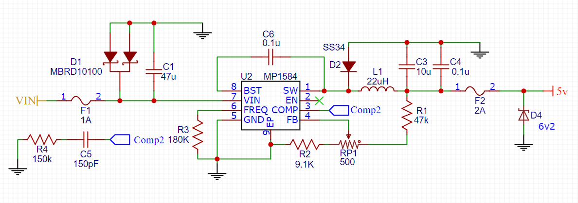 latent jungle
patent ivy
As in this? https://i.imgur.com/TbIDuwI.png (don't mind the terrible formatting)...
latent jungle
patent ivy
As in this? https://i.imgur.com/TbIDuwI.png (don't mind the terrible formatting)...
yeah. but I can undrestand the concern with sizing the zener correctly.
 gusty aspen
I am trying to learn how to make a PCB and what all components I actually need for a very simple board. Can I get eyes on this? Would love to know if what I've done so far makes sense.
 worldly schooner
gusty aspen
I am trying to learn how to make a PCB and what all components I actually need f...
worldly schooner
gusty aspen
I am trying to learn how to make a PCB and what all components I actually need f...
There are several missing connections still, but it appears to be a good start.
I’d probably recommend the use of ground symbols rather than trying to wire all the grounds together though, for more flexibility in arranging your schematic and a cleaner appearance.
Same for power
gusty aspen
worldly schooner
There are several missing connections still, but it appears to be a good start.
Oh the data from the USB-C?
Thank you!
worldly schooner
gusty aspen
Oh the data from the USB-C?
Thank you!
That and the enable for the voltage regulator, at least from a cursory look through.
gusty aspen
worldly schooner
That and the enable for the voltage regulator, at least from a cursory look thro...
Oh yeah okay thanks so much! I feel better, I wasn't sure I was even like on the right track
worldly schooner
I also would recommend a megaohm resistor and a capacitor between the usbc shield and ground.
Past that is whatever you plan to have your gpio connected to.
gusty aspen
I think I accidentally deleted the voltage regulator's ground, I will clean them all up and use ground symbols.
 topaz shadow
How is the JLCPCB PCBA service?
 tough matrix
quite good, I use it regularly
distant raven
Once upon a time I did artisan PCBA lol
I still do it on occasion for small batch assembly, testing, and whatnot.
tough matrix
distant raven
I still do it on occasion for small batch assembly, testing, and whatnot.
I remember 🙂
distant raven
How’s your robotics platform doing? Have you graduated it from the SAMD21?
tough matrix
it has served its purpose, used it for several classes with kids in summer camps - nowadays, i'd probably just use Arduino Alvik instead.
Working on other things now, learning to do proper image recognition and building a self driving car using RPi5 and AI accelerator hat
 sick wharf
Hey all,
Trying to choose the best parts for a keyboard project. The idea is to include a motor that can be used as an input device by turning it manually, as well as an output device by controlling it with a pico. Trying to find the best hardware to approach it. I can see it done here: https://github.com/peng-zhihui/HelloWord-Keyboard
with some Hall effect sensors providing encoder feedback on a brushless drone motor (2204-200kv) but I can’t source that part anywhere. I looked into feedback servos and could get it done with only 180 degrees of motion (think rocker switches) but the full 360 degrees of a regular DC motor (like the 6V adafruit dc motor with encoder) really appeals to me. Stepper motors with encoders could also work, but I’m unsure. Anyone have any thoughts?

GitHub
Contribute to peng-zhihui/HelloWord-Keyboard development by creating an account on GitHub.
Brand new to this so any insight at all would be greatly appreciated
latent jungle
sick wharf
Hey all,
Trying to choose the best parts for a keyboard project. The idea is to ...
You might look if a stepper driver can detect and report the back-EMF of a motor being turned externally.
(but the most obvious method is to use an encoder on the shaft)
sick wharf
I saw a project guide on it, citing that the voltage is too low to read and required an amplifier, but the project guide didn’t provide any insight on how to control the motor programmatically - only how to use it as an input device
https://www.instructables.com/Using-Stepper-Motor-As-Rotary-Encoder/?amp_page=true
sick wharf
latent jungle
(but the most obvious method is to use an encoder on the shaft)
How many “spokes” could I realistically get with an optical or Hall effect encoder?
sick wharf
And would there be any electrical problems with programmatically increasing torque against manual rotation (up to a threshold for the tactile “release” feeling)? I read some stuff about stopped motors burning out pi picos
latent jungle
I would imagine you need to make sure your power supply can handle the stall current of the motor
sick wharf
latent jungle
I don't know what all is available and suitable.
All good, I’m just poking at particulates floating to the surface of the proverbial soup of this project. Trying to get a point to start from haha
supple pollen
sick wharf
How many “spokes” could I realistically get with an optical or Hall effect encod...
Up to a thousand or so
sick wharf
Really! That’s promising
supple pollen
For high position accuracy, I'm fond of optical and magnetic encoders
 burnt frost
What kind of wiring mistake could cause the 3v regulator on the esp32 s3 feather to combust when plugged in via USB?
Shorting 3v to ground?
latent jungle
or shorting it to a higher voltage (like 5)
burnt frost
Interesting alright
cursive sentinel
The latter is more likely. Linear regulators tend to have integrated overcurrent protection and will at least partially shut down when shorted to ground. That doesn't work of you've shorted another, stronger output to it.
burnt frost
I'll definitely check that out next time I have the board that was damaged thanks
If the regulator blows what's the likelihood of that being the only part damaged in the short to higher voltage scenario?
These regulators are like 50 cents, and when we looked the board over for superficial damage the only chip that was showing damage was the regulator but it's not like we can look inside the esp
cursive sentinel
If 5V ended up on the ESP, it's probably toast.
You could desolder the shield to see if there's any visible damage but it'd be a lot of work with nothing conclusive to gain.
topaz shadow
What would the ribbon cable that connects to a DF56L-26P-0.3SD connector on a PCB be called?
topaz shadow
That sounds dangerous. There is a relay that controls 110/240VAC. Look into that and see if that would be better.
supple pollen
topaz shadow
What would the ribbon cable that connects to a DF56L-26P-0.3SD connector on a PC...
That's an exotic connector for "micro-coaxial" cable. https://mm.digikey.com/Volume0/opasdata/d220001/medias/docus/6155/PdfFile_873106.pdf
topaz shadow
https://www.adafruit.com/product/268
that is what I was thinking of, but they might have discontinued that…

The PST has been discontinued. Please check out the IoT Power Relay for an equivalent alternative. The IoT Power Relay has more outlets but otherwise is functionally the same, and at a ...
supple pollen
They now offer this version, as well as the one mentioned in that product description. https://www.adafruit.com/product/2935

Say goodbye to hazardous high voltage wiring and create the Internet of Things with safe, reliable power control. The IoT Power Relay from Digital Loggers is custom designed ...
 trim vale
this is going to be hanging on the wall in a 3d printed case. I thought the Mini Relay could handle 120VAC?
topaz shadow

Get the power to control, and control over power with STEMMA!
It says yes, but 110VAC is a bit too high for me personally.
topaz shadow
supple pollen
That's an exotic connector for "micro-coaxial" cable. https://mm.digikey.com/Vo...
That sounds correct. It is exotic in terms of hobby level. I have an openIPC camera system for a drone and was looking to attempt to see if I can get a longer cable, but yet again I don’t have the frame to know if I need a longer cable.
gusty aspen
I am trying to add a usb-c port for power to my project - I don't want the microcontroller's USB C port exposed because it won't fit flush against the enclosure plus I am making a gift and I don't want the recipient to plug it into their computer and see it as a device, I just want to use USB for power. But it only works with a usb-A to usb-c cable.
I have been reading and what I have gathered is that for it to work with usb-c and a wall charger, I should add 5.1k resistors on the two CC pins. I got a new usb-c female port that has V, GND, several data pins and the CC1 and CC2. I put resistors connected to the CC ports and ground, then connected GND and V to my board, and it still didn't work. The cable is a known good one, and the same setup works with a usb-a to c still
What am I missing? I really want my finished project to have a nice usb-c port for power rather than using the barrel jack.
distant raven
gusty aspen
I am trying to add a usb-c port for power to my project - I don't want the micro...
Do you have a picture of what you’re doing? Or a schematic if you made one
topaz shadow
https://cdn.sparkfun.com/assets/5/2/5/4/2/Serial-Basic-CH340C-and-USBC.pdf
here is a schematic with the two ComputerCraft pins and how they are connected for usb. Is this what you have?
 gusty aspen
I just hooked it up to the multimeter and when I plug in the USB C cable I get millivolts with or without the resistors. Sorry the photo isn't very clear. The button is just stuck to my breadboard ignore it.
On the breakout board I am using V, C2, C1 and GND because I am just trying to get power not data.

If I use A-C cable, multimeter shows 5.1V and with the C-C just millivolts.
I think maybe I was working off incomplete information. I thought this was enough for the PD negotiation but it sounds like I need a specific board/module for that.
This is such a bummer I really want the nice USB c port lol, we only have C to C plugs in our house
worldly schooner
gusty aspen
I think maybe I was working off incomplete information. I thought this was enoug...
What’s on the other end of the C-C usb cable?
topaz shadow
You can use a PD trigger board to get other voltages… I thought 5V was normal…
gusty aspen
worldly schooner
What’s on the other end of the C-C usb cable?
I've tried a bunch of different wall adapters, the apple ones, a Samsung one, even our wall receptacle with USB c.
worldly schooner
5v should be available without any PD negotiation. Is there any visible damage to the board perhaps?
gusty aspen
Yeah I think I need to get a PD trigger board, that is what I was missing.
gusty aspen
worldly schooner
5v should be available without any PD negotiation. Is there any visible damage t...
No, but from what I read it might depend on the charger I'm using which are all meant for smart devices so that makes sense.
And like I said it does work if I use an A to C so it can do the 5V when it's supplied
worldly schooner
Do you have a link for the source of that breakout board?
gusty aspen
Yeah but it's not gonna be helpful lol I bought it on Amazon and it has no docs on the listing: https://www.amazon.com/dp/B0D31GG6WD?ref=ppx_yo2ov_dt_b_fed_asin_title
I've also already bought this as well: https://www.amazon.com/dp/B0C7JL4R5W?ref=ppx_yo2ov_dt_b_fed_asin_title&th=1 and it sounds like that is more like what I need.

Size: 2015mm (0.780.59in)
2pcs*usb type c breakout board

Power an electronic project or convert old hardware to use USB-C power input
Performs PD power negotiation • Supports up to 5A
Not all USB-C power supplies can support all voltages • If the power supply does not support the requested voltage then the next lowest voltage will be provided • The mod...
unique patio
gusty aspen
Yeah but it's not gonna be helpful lol I bought it on Amazon and it has no docs ...
There is https://www.adafruit.com/product/4090 and you can look at the schematic here: https://github.com/adafruit/Adafruit-USB-C-Downstream-Breakout by importing it into Eagle or kicad. Note the comments about the resistors.

Throw out all those Mini and Micro B USB cables you have in a plastic bin - the next generation of USB connectors is here with USB C! You will start to see these connectors pop up on all ...
gusty aspen
unique patio
There is https://www.adafruit.com/product/4090 and you can look at the schematic...
I think this is similar to what I got, but it looks like this does specify that it's "downstream" and I think based on that doc that I am trying to make an upstream port
Maybe this is the Adafruit version of what I am looking for https://www.adafruit.com/product/5807

The HUSB238 USB PD sink chip is neat in that you can either use jumpers (really, resistor selection) to set the desired PD voltage and current or you can use I2C for dynamic querying and ...
I have some other USB-C pigtail cables which just have V & GND. It sounds like the standard is the adapter should be providing 5V automatically but I'm not seeing that happen, which is what's confusing me.
gusty aspen
Problem must have been that USB-C breakout board. I bought a third version and it works.
 stark arch
anyone every run into issues uploading code with USB DFU on STM 32s? I've tried more than a couple times now, and for some reason I can't get my LED to blink. I know it's not a faulty LED, because I directly controlled the pins with a wire and got it to work. I also changed the values that the pins were initizlied with and that worked as well, but I can't seem to get any pin control

 low anchor
Does anyone know where I can source an HDMI connector component like is on here? https://www.adafruit.com/product/3548 I want to design a board that hooks the DDC & CEC lines of a HDMI connection into a RP2040 chip, but I can't seem to find a part like this on DigiKey or Mouser. Maybe I'm just looking in the wrong place though
I'd need a male & a female one

If you love DIY cable-rigging, then these HDMI adapters are right up your alley! Making custom HDMI cables has never been easier. Just grab one of our HDMI ribbon cables, then swap and ...
distant raven
low anchor
Does anyone know where I can source an HDMI connector component like is on here?...

DigiKey Electronics
Order today, ships today. 2086581051 – HDMI HDMI 2.1 Receptacle Connector 19 Position Surface Mount, Right Angle; Through Hole from Molex. Pricing and Availability on millions of electronic components from Digi-Key Electronics.
distant raven
As for the plug, probably lcsc
worldly schooner
Or plug two hdmi cables into a female female board
 plush pagoda
What is the mounting hole diameter for this board? https://www.adafruit.com/product/4440 Can I assume its 2mm?
These displays are small, only about 1" diagonal, but very readable due to the high contrast of an OLED display. This display is made of 128x32 individual white OLED pixels, each one is ...
supple pollen
Looks like 0.1 inch on the learn page https://learn.adafruit.com/assets/93885
clear matrix
Hi all, need some eyes on my project here.
I'm trying to PWM a brushed motor with a low side switch.
VCC = 20VDC
Mosfet is an IRLB3034.
Optocoupler is a TLP785.
The PWM is 5 kHz and has been verified by scope with nice, well defined levels and edges, duty cycle and frequency look good on the low voltage side of the optocoupler.
However, the signal on the gate looks weird as heck.
Any ideas what I'm doing wrong here?


The signal on the gate seen above.
The low voltage side.
 distant raven
I’m not entirely sure that the opto isolator in your design is necessary. I think that’s where you’re probably seeing the signal getting messed up. With the right mosfet, you should be able to drive it with 3.3V
You just need to make sure that Vth is within the difference between your higher voltage and gate voltage
clear matrix
But assuming it was necessary, wouldn't I normally expect a well defined signal on the high voltage side as well?
distant raven
Not necessarily. @supple pollen maybe you have some suggestions?
supple pollen
Some optocouplers are slow to switch, that may be what you're seeing there. That pull-down resistor may take a while to discharge the gate capacitance. You'll probably want a protection diode to absorb the kickback pulse from the motor's inductance (the body diode in the MOSFET will sort-of serve, but I generally prefer a discrete one across the motor windings.
Note that Vth is the voltage at which the MOSFET just begins to conduct, you'll want your gate voltage to be high enough to get the MOSFET to conduct solidly.
 distant raven
supple pollen
Note that Vth is the voltage at which the MOSFET just begins to conduct, you'll ...
distant raven
supple pollen
Note that Vth is the voltage at which the MOSFET just begins to conduct, you'll ...
Thanks for adding that nuance to my Vth comment 🙂
clear matrix
supple pollen
Note that Vth is the voltage at which the MOSFET just begins to conduct, you'll ...
This was my reason to use the optocoupler: I wanted to make sure that the mosfet was fully on by using the battery voltage of 20V rather than 3V3 from the pin.
supple pollen
Ah, that makes sense. I looked it up, it specifies around 6µs rise and fall times, so that's likely not the issue.
 supple pollen
Let's see, 3.3V - Vf=1.4V divided by 120Ω yields about 16mA through the LED, that should be plenty (and then some). CTR is typically 50%, so it would conduct 8mA into the gate, which has about 900pF of capacitance. That should charge it in about 1.1ms, which is a fair chunk of your cycle time at 5kHz
clear matrix
So maybe that scope image isn't far off what I could expect with these components and values..
supple pollen
That could be. It doesn't feel like it should be that slow, I may have whiffed the math somewhat (I'm currently metabolizing a vaccine so I'm a little off)
Gate driver ICs are commonly available for the purpose, which can charge and discharge the gate capacitance with a couple of amperes to minimize the switching time
clear matrix
supple pollen
Gate driver ICs are commonly available for the purpose, which can charge and dis...
I know, but this pcb was made at a time of ignorance 😦
Maybe I'll try just removing the optocoupler and make a wire from the cathode pin to the output.
So skipping the optocoupler and keep the resistors and run the mosfet from the IO pin.
distant raven
Might just drop a BJT in 🤷♂️
supple pollen
I doubt that would work well, as was pointed out, 3.3V isn't enough to get the MOSFET to conduct well.
distant raven
In terms of gate drivers, this seems reasonable. https://www.digikey.com/en/products/detail/1EDN7512BXTSA1/6565753

DigiKey Electronics
Order today, ships today. 1EDN7512BXTSA1 – Low-Side Gate Driver IC Inverting, Non-Inverting PG-SOT23-5-1 from Infineon Technologies. Pricing and Availability on millions of electronic components from Digi-Key Electronics.
supple pollen
That looks like a solid choice
clear matrix
Hmm, I'm looking at a board redesign. Oh well, I had plenty of delays so far anyway.
distant raven
Think of all the great knowledge you’re getting to put towards future projects, that’s really the cool part of all this
supple pollen
You might be able to bodge it into the optocoupler footprint
clear matrix
distant raven
Think of all the great knowledge you’re getting to put towards future projects, ...
Definitely agree. Thanks for your inputs. I'll try with the driver.
clear matrix
supple pollen
You might be able to bodge it into the optocoupler footprint
If nothing else then just as proof of concept. I will, thanks.
supple pollen
That's what SparkFun recommends https://www.sparkfun.com/tutorials/109 and I agree
urban lark
supple pollen
That's what SparkFun recommends <https://www.sparkfun.com/tutorials/109> and I a...
was curious which tutorial, got 404
supple pollen
Oh dear, SparkFun apparently revamped their site. It was a tutorial on what to do when your first PCB doesn't work: it suggested patching, bodging, modifying whatever you have to, to get the original board working, before you respin it, so you don't have to respin it a bunch more times than necessary
burnt frost
On the esp32s3 feather if I wanted to not use the battery connector and instead hard wire in the battery that could be done by connecting to bat and ground on the board right? Or is ground supposed to be used with the output on the 3v regulator?
I figure it would be okay because the ground on the connector and ground on the board are connected according to my multimeter
unique patio
burnt frost
On the esp32s3 feather if I wanted to not use the battery connector and instead ...
all the grounds are the same
BAT and the battery connector +V are connected directly together. what kind of battery?
unique patio
burnt frost
3.7 v Lipo
sorry for the delay, that's all fine
pale grove
RGB LED question.
Could/should this work?

I just got my PCBs here but can't seem to get the LEDs to turn on
Not sure where to start to debug it
distant raven
Just tracing through the circuit, the DMG3415 will be off when voltage is applied to the gate, so off when D4 is high.
I’d suspect maybe a bad connection but quick glance it might work?
pale grove
Okay one more problem.
I also have a speaker connected over here.
But I am not getting any sound back it seems

Nevermind got that also
 celest umbra
afternoon
i have a question regarding the 7in display(Product ID: 2353)
https://www.adafruit.com/product/2353
and RA8875 Driver Board (Product ID: 1590)
https://www.adafruit.com/product/1590
The learn page for the RA8775 module leads me to believe it will not be a bottleneck refresh rate wise
in the datasheet (Photo 1) it mentions the rising and falling times for the display are (10-20ms) and (15-30ms) respectively
and i see that it elaborates on these in note(Photo2)
so per pixel the total response time (T_ON + T_OFF) ranges from 25 ms (best case) to 50 ms (worst case).
does that mean best case scenario im limited to 40fps and worst 20fps
im driving the ra8775 with a teensy 4.1 and it will only be displaying values bode plots or bar graphs or xy plot or something similar to an analogue meter, so im not going to be doing anything graphically intensive but i need to have a decent refresh rate


This 7.0" TFT screen has lots of pixels, 800x480 to be exact, and an LED backlight. Its great for when you need a lot of space for graphics. These screens are commonly seen in consumer ...

Have you gazed longingly at large TFT displays - you know what I'm talking about here, 4", 5" or 7" TFTs with up to 800x480 pixels. Then you look at your Arduino. You love ...
worldly schooner
celest umbra
afternoon
i have a question regarding the 7in display(Product ID: 2353)
https:/...
No, it would only be a limiting factor if you’re really trying to flash the screen black and white as fast as possible. For general use this is not going to be a limiting factor on your overall frames per second.
As far as I know the biggest bottleneck aside from actual rendering of frames in the microcontroller would be the spi interface between the MCU and ra8875. I don’t have any personal experience with this particular chip, but assuming it behaves like most spi tfts, you’re driving 800x480 pixels of 16-bit color across a single data line that maxes out at around 40 mhz? Rough calculations show a theoretical max fps of 40000000/(800x480x16) = 6.51 frames per second.
This assumes you’re redrawing the full frame every time, which probably isn’t the case for your application, but for something like video playback this setup does suffer from the spi bottleneck.
I’m sure the ra8875 with its buffered ram allows for partial frame rendering, which should alleviate these restrictions.
celest umbra
worldly schooner
As far as I know the biggest bottleneck aside from actual rendering of frames in...
that would be depressingly low
thankfully im not doing videoplayback
celest umbra
worldly schooner
I’m sure the ra8875 with its buffered ram allows for partial frame rendering, wh...
it does
very good point
thank you for the info
celest umbra
worldly schooner
As far as I know the biggest bottleneck aside from actual rendering of frames in...
"Have you gazed longingly at large TFT displays - you know what I'm talking about here, 4", 5" or 7" TFTs with up to 800x480 pixels. Then you look at your Arduino. You love your Arduino (you really do!) but there's no way it can control a display like that, one that requires 60Hz refresh and 4 MHz pixel clocking. "
this is the text they got on the product page for the 8875
i think the max read o the 8775 is 22mhz iirc
so not sure how can they get 60hz but i hope i can
worldly schooner
celest umbra
so not sure how can they get 60hz but i hope i can
The 40-pin display needs a 60hz refresh and a 4MHz pixel clock, and that’s what the ra8875 handles for you, so the microcontroller doesn’t have to. That doesn’t necessarily mean you can push 60 frames a second from your mcu to the ra8875, it means that the ra8875 will drive whatever it has in memory to the 40-pin display 60 times a second to keep a stable image on the display.
clear matrix
distant raven
In terms of gate drivers, this seems reasonable. https://www.digikey.com/en/prod...
Hi again, just coming back to this talk because the gate driver you suggested is not suited for the power supply I'm using (a 20V power tool powerbrick, so probably peaking a little over max VCC).
Instead, I found this one, NCP81074, which seems to fit my criteria:
- 3V3 logic valid input at the 18-22V-ish power supply.
- Tolerates somewhat higher VCC than expected battery pack max.
As I read it, the absolute max VCC is 24V, so we're good, and High threshold is 1.9-2.3V but will tolerate 3V3.
Do I read that right in your opinion?
Datasheet:
https://www.onsemi.com/download/data-sheet/pdf/ncp81074-d.pdf
I also take the liberty of pinging you, @supple pollen ^^
distant raven
clear matrix
Hi again, just coming back to this talk because the gate driver you suggested is...
Seems fine
clear matrix
distant raven
Seems fine
Thanks for taking a second look.
pale grove
Got another question for mass production of a PCB.
rigid vs. flex PCB
Is there a big difference in cost between the two?
Or just a few cents?
worldly schooner
Depends on vendor and volume. I’d take that question to whoever is going to make your PCBs for the best answer.
supple pollen
I suspect it's more than a few cents, but I agree with Hem, the PCB house can tell you (most of them have online quoting tools)
tough matrix
pale grove
Got another question for mass production of a PCB.
rigid vs. flex PCB
Is there...
when you say mass production, do you mean thousands of boards? tens of thousands?
latent jungle
millions?
distant raven
 pale grove
tough matrix
when you say mass production, do you mean thousands of boards? tens of thousands...
pale grove
tough matrix
when you say mass production, do you mean thousands of boards? tens of thousands...
Around 1k pcs
 pearl obsidian
now that my code is almost complete I need a small clear acrylic case 4" by 2". Been searching but I can't find any thing that size. Any ideas on where I could find something. I heard that Adafruit has a bunch of 3D printed enclosures but I can't find anything that isn't for LED matrixes which doesn't nothing for me. Help PLEASE.
Joe B
supple pollen
Craft stores often have such things. There are also generators that can make laser cutting instructions for a case sized to your specifications.
 lavish geyser
I am looking for a neopixel-type smd RGB LED for a project that is stable from ~3.0-2.7v. Ideally side emitting, but that's negotiable... All my searching has come up dry so far.
worldly schooner
lavish geyser
I am looking for a neopixel-type smd RGB LED for a project that is stable from ~...
Green and blue LEDs typically have a forward voltage of 3v, so all of the addressable rgb LEDs are rated for a minimum of 3.5v IIRC.
lavish geyser
worldly schooner
Green and blue LEDs typically have a forward voltage of 3v, so all of the addres...
Ah, I hadn't considered that.... That's pretty inconvenient lol
worldly schooner
You may need to consider a boost converter if rgb is needed at low voltage.
lavish geyser
Realistically it probably means either I go with two cr2032 cells, or just say to heck with it and go lipo
Anyways, thanks for the help!
 thorny reef
Hi All, Anyone got any recommendations for a good a readily available IEEE 802.3af PD chip ?.
pearl obsidian
supple pollen
Craft stores often have such things. There are also generators that can make la...
Just a little bummed because @unique patio had mentioned something about 3D printed cases. Do you have any links or names of laser cutting services? THX
supple pollen
I've had good luck with Pololu, Ponoko, and SendCutSend.
Sometimes local libraries or makerspaces can help too
unique patio
pearl obsidian
Just a little bummed because <@329766224093249548> had mentioned something about...
we have done some experimentation with 3D printing services that print clear (I think resin printing)

Here is a cute and minimal enclosure for your TRRS Trinkey to keep it safe during use and transport. This case has been custom-designed and 3D printed to accommodate the reset button ...
2 x 4 x what
pearl obsidian
2.0" X 4.25" X 1.25" Is exactly what I am looking for. ProtoStax has some nice enclosures but they're too wide. Basically I want to put a Feather Sense nRF52840 and a Li Ion battery in the case. I have some very small components, switches, LEDs that I want to mount on the top, maybe the side. And I need a slot to pass a standard I2C 4 wire cable out of the enclosure. The cable is about 6" long and is soldered to the Sense I2C pins. At the end of the cable is a BNO085 board.
I have all the code working, except for the graphic display. I tried making a "case" out of ABS moldable plastic but that was a failure as well as the white moldable plastic on the Adafruit site.
pearl obsidian
unique patio
like https://www.adafruit.com/product/6015
too bad it's not longer and wider!!!
 hushed ermine
if you need that exact size, it's going to be custom, but if you're a little flexible, there's tons of stuff out there.
hushed ermine
pearl obsidian
2.0" X 4.25" X 1.25" Is exactly what I am looking for. ProtoStax has some nice e...
https://www.polycase.com/wc-21 for example

Polycase
Shallow clear cover enclosures for IoT applications
pearl obsidian
I don't know why I had those dimensions in my head! Just went back and measured and am looking at 4" L x 1.5" W x 1" H.
Did look on the polycase but they didn't have anything.
☹️
pearl obsidian
BAH! just ordered some small acrylic sheets that I'll cut myself. Thanks anyway guys
 sharp pilot
hey, anyone know a good source for coil springs?
2.2Ft Long, 35x6x0.5mm/1.38 x 0.24 x 0.02 inch. i genuinely cannot find them other than one amazon listing, wich is unavalible.
unique patio
sharp pilot
2.2Ft Long, 35x6x0.5mm/1.38 x 0.24 x 0.02 inch. i genuinely cannot find them oth...
compression or extension? Spring manufacturing companies can make you one. Just search for "custom springs"
supple pollen
McMaster-Carr? Thomas register?
sharp pilot
unique patio
compression or extension? Spring manufacturing companies can make you one. Just ...

For less than 28 a spring? Idk…
unique patio
sharp pilot
https://media.discordapp.net/attachments/646025812214022144/1347111321237327912/...
This is called a "rotor" spring, it seems, as opposed to a "coil" spring (which is a more typical cylinder shape
sharp pilot
Coil/quill spring as far as I know. Never seen it called that, rotor springs are the other way around…
distant raven
Torsion spring is another name
sharp pilot
Ah
low anchor
Would it be possible to use a pi pico to intercept key combinations on a keyboard plugged into a computer? There's an annoying lack of low cost KVMs with keyboard shortcuts so I'm wondering if I could use a pico to add functionality to a cheap one
worldly schooner
I’d honestly be surprised if it wasn’t. The PIO usb host has been used for keyboard remapping before, so that should be pretty easy.
low anchor
Would it be possible to just 'sniff' the USB packets or do I need to make it host the keyboard & send the packets to the PC itself
worldly schooner
That I’m not sure. In theory it could work, but I don’t know if anyone has actually tried it…
latent jungle
low anchor
Would it be possible to just 'sniff' the USB packets or do I need to make it hos...
Sniffing is easy. Injecting packets, not so much.
It’s much better to act as a repeater.
worldly schooner
latent jungle
Sniffing is easy. Injecting packets, not so much.
It’s much better to act as a...
I don’t think there’s any injection here, sounds like he wants to trigger a button or something by a key combination. As long as he’s okay with passing the combination to both host and sniffer it should work
clear matrix
Hey guys, need a few suggestions with a low side MOSFET switch controlling a DC motor.
Whenever I connect the motor to it's connector, it immediately starts.
When desoldering the mosfet, it doesn't happen, but I've changed them twice now, so unless they're just hard to handle and solder without ruining them, I'm at a loss.
I previously debated the same project here, where I drove the gate with an optocoupler, but it has been swapped for a dedicated gatedriver and I've confirmed a solid PWM signal on the gate with my scope.
The fet is an IRLB3034. The physical connections can be seen here.
GND is battery ground, M- is the negative tab on the motor.
 latent jungle
Need schematic
clear matrix
Sorry, it hasn't been updated yet.
The pulldown is gone and the optocoupler is now a NCP81074A.
 latent jungle
clear matrix
Sorry, it hasn't been updated yet.
The pulldown is gone and the optocoupler is n...
latent jungle
clear matrix
Sorry, it hasn't been updated yet.
The pulldown is gone and the optocoupler is n...
If the optocouple is missing, what is the gate connected to?
clear matrix
latent jungle
If the optocouple is missing, what is the gate connected to?
The dedicated gate driver chip.
latent jungle
clear matrix
The dedicated gate driver chip.
Where is that in the schematic?
clear matrix
latent jungle
Where is that in the schematic?
Same place the optocoupler was before, just rewired a bit because it's a different chip.
But I did measure both input and output on it, and it seems fine.
If I got something messed up, I would have exploded due to the power source being a power tool battery (don't ask how I know).
latent jungle
So, what is the mystery driver in this case?
and what kind of motor is it?
clear matrix
latent jungle
So, what is the mystery driver in this case?
and what kind of motor is it?
NCP81074A
The motor is a DC motor from an airsoft gun. Nothing fancy.
latent jungle
I don’t know what kind of motors are used in an airsoft gun.
clear matrix
https://www.onsemi.com/download/data-sheet/pdf/ncp81074-d.pdf
This is the driver.
clear matrix
latent jungle
I don’t know what kind of motors are used in an airsoft gun.
Brushed DC motor with a positive and negative tab. I don't have any documentation for it, unfortunately.
latent jungle
clear matrix
Brushed DC motor with a positive and negative tab. I don't have any documentatio...
Where is the fly back diode?
clear matrix
latent jungle
Where is the fly back diode?
There isn't one.
Experience has shown that for regular (non PWM, just dumb on/off) switches, it wasn't necessary.
It may be necessary for PWM applications, but in this case, I don't even get to the part where PWM is applied.
latent jungle
Uh, okay. I guess you have more (positive) experience than I have. It’d be nice if you could share HOW this driver is connected.
It’s necessary in all motor applications. When the applied voltage disappears, that energy needs to go somewhere.
You might get away with the switching FET’s body diode in that “on/off” case. But, that’s going to breakdown eventually.
clear matrix
Maybe I should have updated my schematic before asking, sorry it's a bit messy, but basically, the driver is wired like this:

So R1 and R2 not used, L1 is the motor.
Straight from the data sheet.
clear matrix
latent jungle
You might get away with the switching FET’s body diode in that “on/off” case. Bu...
I was actually considering if I got drain and source swapped, that would explain why it just starts as soon as the circuit is powered, I suppose.
Are MOSFETs very sensitive to heat during soldering? I suppose I could simply have ruined all those I tried by overheating them.
latent jungle
clear matrix
I was actually considering if I got drain and source swapped, that would explain...
Yes. if drain and source were switched then the body diode would be forward biased and start conducting.
clear matrix
latent jungle
Yes. if drain and source were switched then the body diode would be forward bias...
But looking at the picture from my layout program, that doesn't seem to be the case, unfortunately.
latent jungle
yeah, I’m not sure what to suggest without seeing the actual schematic.
clear matrix
latent jungle
yeah, I’m not sure what to suggest without seeing the actual schematic.

I updated the schematic.
Here's the driver again:
https://www.onsemi.com/download/data-sheet/pdf/ncp81074-d.pdf
MOSFET is not IRF540, but another N channel hexfet, IRLB3034, should be pin compatible.
I see that VGS is actually about 2-3V too high for this MOSFET.
Still, the gate voltage is held low by the driver, so that shouldn't be why the motor immediately turns on when power is applied.
Gotta go to sleep, I think I have a few points to check before coming back to ask again.
latent jungle
clear matrix
Gotta go to sleep, I think I have a few points to check before coming back to as...
as a next step, take that schematic and write down what voltages you see on a DMM at all of the wired nodes. (like IN+ and OUTH) of the driver
clear matrix
latent jungle
as a next step, take that schematic and write down what voltages you see on a DM...
Alright. I can also do scope images.
clear matrix
I'll look into it, thanks for now.
gusty aspen
Does this Neopixel board look ok? The idea is to chain these, there will be 4 of them, using the 3535 leds. There's a single 1000uf capacitor attached to the 5V & GND before the input to this.
 distant raven
gusty aspen
Does this Neopixel board look ok? The idea is to chain these, there will be 4 of...
distant raven
gusty aspen
Does this Neopixel board look ok? The idea is to chain these, there will be 4 of...
Seems okay, only change i would make is making the 5V rail a solid fill on the top layer
latent jungle
gusty aspen
Does this Neopixel board look ok? The idea is to chain these, there will be 4 of...
Adjust the ground plane so that the data signal on “top” of the board has ground under it.
I would also add a couple more vias on the GND pads of the connectors.
gusty aspen
latent jungle
Adjust the ground plane so that the data signal on “top” of the board has ground...
Thanks good catch!!
gusty aspen
latent jungle
I would also add a couple more vias on the GND pads of the connectors.
Can you elaborate on this?
latent jungle
gusty aspen
Can you elaborate on this?
you want more than one via so decrease the impedance to the ground plane.
if you consider the loop the current follows, most of it will be trying to go through that single via
gusty aspen
latent jungle
you want more than one via so decrease the impedance to the ground plane.
Oh I see now, okay!
Thanks so much!
tough matrix
having a capacitor for each neopixel might be an overkill; on the other hand, 0.1uf caps are dirt cheap
distant raven
tough matrix
having a capacitor for each neopixel might be an overkill; on the other hand, 0....
Yeah, the data sheet assumes you’re making a flexible strip of LEDs where the flex PCB have incredibly low parasitic capacitance and the cap on each LED is necessary for stability of the power rails.
But standard 1.6mm PCB have more than enough parasitic capacitance if you’re using pours for your power and ground
supple pollen
clear matrix
I'm not sure you want to connect VCC1 and VCC2, presumably one is the logic voltage and one is the gate drive voltage
tulip swift
gusty aspen
Does this Neopixel board look ok? The idea is to chain these, there will be 4 of...
Just a thought. If you need logic level shifting for your design to go from 3.3V to 5V on the data line, maybe have an option on the board for a built in level shifter? Perhaps a single gate shifter and a jumper to choose a 5V (shifter bypass) or 3.3V (routed through shifter) data line? Or actually now that I think about it, you don't need a bypass. Just put the shifter on and it will be both 3.3V and 5V tolerant.
gusty aspen
tulip swift
Just a thought. If you need logic level shifting for your design to go from 3.3V...
I know I don't need the level shifting for this project, but thank you!
clear matrix
That's a great observation, I'll recheck the datasheet for that. Thanks.
I don't suppose this would explain why the mosfet is on as soon as the circuit is powered (I confirmed the gate low with my scope).
 calm kiln
I have a very basic electronics design question. I'm connecting some indicator 5mm indicator LEDs to an ESP32 Feather. From my calculation, I need a 150 Ohm resistor, but I've tested it without and it seems fine. Is it really required? Skipping it will make assembly of the project in the case a bit easier, but am I just being lazy?
Somehow I always skated around this in my education.
latent jungle
calm kiln
I have a very basic electronics design question. I'm connecting some indicator 5...
For indication, you probably don’t need to drive the LED at its maximum forward current.
And yes, you need a resistor. Otherwise the LED draws as much current as it can which is certainly more than the IO pin’s driver can handle.
Eventually either the LED or pin will burn out. (probably the pin)
calm kiln
latent jungle
For indication, you probably don’t need to drive the LED at its maximum forward ...
Great, appreciated. Thanks.
One LED each, separate pins and common ground, I treat these as parallel?
gusty aspen
distant raven
Seems okay, only change i would make is making the 5V rail a solid fill on the t...
Okay this might sound like a stupid question but I am a total newbie here
Does this mean I have to add another layer, or do I fill the top layer which also has my signal traces and then essentially everything that isn't signal or pads gets power? Do I still have to add vias or are there like, no longer 5V tracks?
distant raven
Fill the top layer
distant raven
Every other suggestion works with the top layer being filled with a power plane.
gusty aspen
Thank you! I tried it out in KiCad and I see how that works. Looks great, now I just have to handle the signal tracks, seems much simpler 🙂
clear matrix
supple pollen
I'm not sure you want to connect VCC1 and VCC2, presumably one is the logic volt...
I checked again and I don't see any indication, although your observation was good. Unless I'm missing something?

 viscid coral
This is going to be a hyper-specific question, but does anyone know how the EAGLE font size translates to KiCad's font size? In EAGLE you set a single number for the font size, but in KiCad you specify width and height. I've been measuring a few different characters ("L", "E", "C", "8", etc.) with a few different font sizes to figure out a scaling factor if there is one. But not having any luck. Also been trying to check the documentation.
thorny reef
Hi all, just need some conformation on a schematic if you can...... V+ & V-...... are these the 48 - 52V connections from E.G a switch?. if so i assume i plug these into a suitable POE Module [or circuit] to give me the desired voltage ?.
EDIT - Some context i'm wanting to add POE to my project, have managed to get the Ethernet sorted out just POE i'm not 100% on.
 gusty aspen
viscid coral
This is going to be a hyper-specific question, but does anyone know how the EAGL...
gusty aspen
viscid coral
This is going to be a hyper-specific question, but does anyone know how the EAGL...
This is a good question honestly, the way kicad measures the fonts really confused me. I've been setting the height and thickness because I'm ordering through JLC PCB and they have the minimum height and line thickness on their specifications. So I think that's why they actually have those parameters instead of a font size, because the manufacturers will actually have limits for the height and thickness, whereas a font point size can vary a lot based on the actual font
tough matrix
viscid coral
This is going to be a hyper-specific question, but does anyone know how the EAGL...
I think short answer is "no way to match exactly". Relation between "font size in points" and actual size of letters in font is complicated enough (see https://www.thomasphinney.com/2011/03/point-size/), even before we introduce second parameter - most importantly, it depends on font.

It’s easy enough to determine that a point is 1/72 of an inch, and used to be about 1/72.27 in the days before digital type. But the challenging question is, what part of a 12-point font is 12 poin…
my experiments show that for the default KiCad font, "height" is the same as height of a capital letter such as X; thickness is thickness of strokes, so this is logical enough.
I no longer have Eagle, so I can't experiment there, but the successor of Eagle, Electronic design component of Fusion 360, seems to use the same convention for height (at least for their "proportional" font)
thorny reef
Review Request. ESP32-WROOM32, W5500 Ethernet POE Custom board
viscid coral
gusty aspen
This is a good question honestly, the way kicad measures the fonts really confus...
Thanks for the feedback!
viscid coral
tough matrix
I think short answer is "no way to match exactly". Relation between "font size i...
Figured as much. Thanks for the feedback!
 gilded grail
Hi, I'm working on a project and had gotten some feedback here on the initial buys for the project and wanted to maybe see if someone had an idea on something that might work a little better for my application.
So after talking with some people here I had ordered a quadrature encoder (linked below)
https://www.pololu.com/product/2590
The sensor works perfectly for the application that I'm using it for. BUT it's far too tiny for what I'm using it for. Is there something else that someone could recommend that operates almost exactly the same but in about a 3x to 4x form factor?

Add quadrature encoders to your LP, MP, or HP micro metal gearmotors (extended back shaft version required) with this kit consisting of two sensor boards, two 3-tooth encoder wheels, and two 5-tooth encoder wheels. The installed system does not exceed the 12 mm × 10 mm cross section of the motors and extends only 5 mm beyond the plastic motor e...
distant raven
gilded grail
Hi, I'm working on a project and had gotten some feedback here on the initial bu...
Maybe something like this with a 3D printed wheel would work better for you? https://www.digikey.com/en/products/detail/omron-electronics-inc-emc-div/EE-SX3162-P1-Z/6946418

DigiKey Electronics
Order today, ships today. EE-SX3162-P1-Z – Optical Sensor Through-Beam 0.197" (5mm) Module, Slotted from Omron Electronics Inc-EMC Div. Pricing and Availability on millions of electronic components from Digi-Key Electronics.
gilded grail
It might, but one thing I don't see on all the sites for these parts is any dimensions of the part.
 charred merlin
gilded grail
It might, but one thing I don't see on all the sites for these parts is any dime...
charred merlin
gilded grail
It might, but one thing I don't see on all the sites for these parts is any dime...
page 4/5 in the datasheet for the part skerr just posted: https://omronfs.omron.com/en_US/ecb/products/pdf/en-ee_sx3162.pdf
gilded grail
thank you, I'm going to try them, they look like the right size based on that.
Really appreciate the input!
supple pollen
gilded grail
Hi, I'm working on a project and had gotten some feedback here on the initial bu...
Maybe look at the AS5600? There are breakout boards for it available too.
tough matrix
gilded grail
thank you, I'm going to try them, they look like the right size based on that.
Adafruit also sells a similar interrupter:
https://www.adafruit.com/product/3985
This T-Slot Photo Interrupter with Cable is a simple plastic sensor with two elements - an IR LED and an IR photo-transistor, situated across a U-shaped gap. You can control the IR LED and ...
clear matrix
@latent jungle Hi, you previously helped me troubleshoot my driver+MOSFET circuit (started with optocoupler).
I made some changes and hope you would have a minute to review it.

R4 added on output to limit current through the zener diode - Intentionally connected only to out high so pulling the gate low is fast.
13V/5W zener added to avoid overvoltage on the Gate R4 is chosen to keep the current as high as possible without exceeding the zener diode's max current/effect.
Schottky diode added as flyback for the brushed DC motor load.
VCC is 24V (or slightly less).
latent jungle
clear matrix
<@312943079160283137> Hi, you previously helped me troubleshoot my driver+MOSFET...
what is the motor driver?
clear matrix
latent jungle
what is the motor driver?
https://www.onsemi.com/download/data-sheet/pdf/ncp81074-d.pdf
Sorry forgot that one.
It's the A version I'm using.
latent jungle
clear matrix
R4 added on output to limit current through the zener diode - Intentionally conn...
I don’t follow why you are powering the FET driver with 24V. Neither the FET driver nor the FET itself is rated for 24V (continuous).
And is a FET rated for 300 A really necessary?
clear matrix
latent jungle
I don’t follow why you are powering the FET driver with 24V. Neither the FET dri...
It's a hobby project, so I hope it's okay it doesn't make sense.
24V is because I have 20V power packs for my power drill. They just sit around so I started to make this controller for use in my hobby gear.
The toy is made for 10-12V DC so I figured I'd just PWM at 50% and call it a day.
The FET is rated high because I want to make sure it's up to the task.
24V is actually a typo, the battery pack peaks a just under 22V, 24V is the stated absolute maximum in the driver data sheet so I thought it was all good.
latent jungle
Read the sentence, the very important sentence, under the “Recommended Operating Conditions” table….
clear matrix
latent jungle
Read the sentence, the very important sentence, under the “Recommended Operating...
I did but at the time, I thought that operating under absolute max would be ok, despite the warning.
If not, could I simply move the zener diode away from the output and instead insert it in series with the supply pins?
Or, if that doesn't work, I suppose will need to make an entire secondary power supply circuit just for the gate driver..
inland jungle
are OUTH and OUTL supposed to connect to the same gate?
clear matrix
inland jungle
are OUTH and OUTL supposed to connect to the same gate?
Yes, the driver has separate pins for charging and discharging the gate. I suppose in case you want to have different profiles for those two actions.
In this case, it just means I can discharge faster and get a slightly more efficient cycle.
 lime cobalt
In a revision of a current project (it's a guitar pedal DSP thing), I'm planning on switching to a new codec which is more readily available and inexpensive, the TLV320AIC3104. What's interesting about this codec is that it offers differential line input and output. I've attempted to use this feature in my buffer preamps, but I'm worried that I'm not quite doing it right both with the preamp and the jack. In my first design, I ended up with much more noise than I had anticipated, so I'm really trying to get it right this time to avoid running into that problem again. Any help would be greatly appreciated!!


 lime cobalt
On another unrelated note, when working with QSPI RAM with the RP2350, GPIO0 is typically used as the chip select (XIP_CS1n). I'm assuming that means we can't use GPIO0 for other functions?
distant raven
lime cobalt
On another unrelated note, when working with QSPI RAM with the RP2350, GPIO0 is ...
I’d assume as much
 drowsy drift
lime cobalt
On another unrelated note, when working with QSPI RAM with the RP2350, GPIO0 is ...
drowsy drift
lime cobalt
On another unrelated note, when working with QSPI RAM with the RP2350, GPIO0 is ...
If your desire is to not have two buttons but one button that acts as both BOOTSEL and as a GPIO, you can do the trick that Limor does by feeding the button to a spare GPIO with a schottky diode. See the QTPY RP2040 schematic: https://learn.adafruit.com/assets/101678
 tardy lagoon
Less hardware design and more just hardware. Does anyone have advice for soldering onto the pads of the heatsink embedded PCBs for things like the 1W/3W LEDs? I'm having a heck of a time even with flux, and when I finally get a successful set of solder joints they are ugly as heck
distant raven
tardy lagoon
Less hardware design and more just hardware. Does anyone have advice for solderi...
Hot air + iron
tardy lagoon
distant raven
Hot air + iron
Thats what I was worried about. Thank you!
distant raven
tardy lagoon
Thats what I was worried about. Thank you!
Yeah, you have to hold some threshold temperature enough that it doesn’t suck so much energy from your iron
tardy lagoon
distant raven
Yeah, you have to hold some threshold temperature enough that it doesn’t suck so...
Got it! That makes sense!
latent jungle
tardy lagoon
Less hardware design and more just hardware. Does anyone have advice for solderi...
Hot plates help too (if parts are on one side.)
inland jungle
I've had success using something like this: https://www.amazon.com/Weller-D650PK-Industrial-Soldering-Gun/dp/B000TDGI18/

Weller transforms hand soldering. The art of hand soldering has been around for a very, very long time, thousands of years in fact. But it was only until 1941 that a transformer based instant heating soldering method was developed by an impatient American radio repairman who was tired of ...
 shut latch
Hey all, does anybody have some tips for how to connect 64 potentiometers to a raspberry pi? I've got the MCP3008, but it only has 8 channels in. I understand I can use analog multiplexers to add many more channels, but I have no idea which one to get. Is there a better way to do this? Or is there a specific multiplexer chip that will make this simple?
 timber wyvern
You'd need to use multiple MCP3008's, with separate GPIO wired to each one's chip-select and interacting with them one at a time.
If you wanted to get fancy/complex you could setup a separate pin only for DOUT from each MCP3008 and manage them all in parallel. The parallel approach would be far easier on a microcontroller instead of a RPi though most likely.
shut latch
Looks like I can do this x2? https://www.instructables.com/MegaMUX-32-Channel-Multiplexer-Tutorial/
32 channel analog multiplexer, and then I use gpio pins for selecting channels. I can run two of these into the MCP3008, unless I run out of GPIO pins
oof but they are pretty expensive, 15 bucks each
where the budget multiplexers at?
timber wyvern
It'd be a LOT simpler to just use 8 MCP3008's.
You can use individual GPIO's wired to the CS (Chip Select) pin on each MCP3008 to select individual chips to read from.
To your software code it'd only see 'one' MCP3008, you'd read all 8 channels, then change which GPIO was on to select the next MCP3008, repeat. So it'd be two simple nested loops, one to cycle the chip-select pins, then the inner to read all eight values from that MCP3008, repeat.
shut latch
Hmmmm I see your point.
On the other hand, MCP3008 is $3+, while the CD4067 multiplexer is around $0.50
And how hard could the code be to count in binary from 1-16?
So I get one MCP3008, and hook up 2-4 multiplexers, (i might only use 32 potentiometers), that requires I think 12-20 GPIO pins for control. Is this a bad idea for other reasons?
worldly schooner
Not if you can afford to use 12-20 GPIO pins, and your polling rate can be low enough to split the 200k samples per second across 64 pots with ample headroom. Timing may become an issue for software on a raspberry pi, but if you have sufficient headroom for error it does seem to be a valid approach.
timber wyvern
shut latch
So I get one MCP3008, and hook up 2-4 multiplexers, (i might only use 32 potenti...
With the multiplexers feeding into a single MCP3008 you'd also have to worry about giving the switched signal time to settle, like with a KVM when you switch channels it has to re-sync to the video signal? It's like that.
But with the multiplexing being on the digital side if you go with multiple MCP3008's instead there's no settling time by comparison.
But it depends also on are we talking '60fps' update speed, or kilohertz update speeds?
 woven grail
Hi, I am looking to drive a bunch of digital servos using one of these adafruit servo hats for RPi:
https://learn.adafruit.com/adafruit-16-channel-pwm-servo-hat-for-raspberry-pi/powering-servos
My servos can accept 5v-8.4V: https://www.aliexpress.com/item/1005007811142605.html
I was wondering if it is possible to supply 7.4V through the servo hat via a RC liPo battery such as:
https://www.componentshop.co.uk/7-4v-1000mah-35c-70c-lipo-rc-battery-giant-power.html ?
The documentation on the adafruit website states the hat accepts 5V-6V via external power source but if the power source goes directly to the servos surely supplying a higher voltage wouldn't be an issue if he servos are able to accept it? I want to make sure in case I accidentally destroy the hat/pi/servos.

16 channels of servo-bustin' power for your Pi

Dimensions: 65.4 x 34.7 x 13.8 mm
timber wyvern
woven grail
Hi, I am looking to drive a bunch of digital servos using one of these adafruit ...
TL;DR: It looks like yes you could, though looking at the schematic of the HAT https://cdn-learn.adafruit.com/assets/assets/000/033/736/original/raspberry_pi_schem2.png and masking https://cdn-learn.adafruit.com/assets/assets/000/033/737/original/raspberry_pi_fabprint.png you might damage the power LED on the hat at high enough voltages.
Maybe just add a UBEC like https://www.adafruit.com/product/1385 in between the LiPo battery and the hat?
woven grail
timber wyvern
TL;DR: It looks like yes you could, though looking at the schematic of the HAT <...
Thanks.
I was actually hoping that I would be able to drive the servos at a higher voltage as I might need the extra torque with the weights I am trying to hold with the servos. I actually found this thread asking something similar but they appear to be using a different revision of the board:
https://forums.adafruit.com/viewtopic.php?p=1022892&hilit=servo#p1022892
I saw this comment:
"Yes. The MOSFET is connected in-line with the power so that it will turn on if the polarity is correct and turn off if it is reversed. Cutting the right leg breaks the connection to the power rail for the servos.
If the solder pads from the MOSFET are not destroyed, you could also bypass it by soldering a jumper from the tab to the right-side leg."
I assume I can solder the +V from the DC barrel input to where the mosfet leg was soldered to?
I am very much a beginner at soldering and these sorts of circuits so want an understanding of what I should be doing in case 😅
timber wyvern
Can't say for sure, but yes good catch on the reverse-polarity MOSFET, that would possibly need to be removed.
Might be easier to look into changing the lever or gear you're gonna use on the servos to adjust the torque higher instead? It depends on more project specifics, but 'higher voltage' isn't the only solution if you don't want to dive into soldering, etc.
woven grail
timber wyvern
Can't say for sure, but yes good catch on the reverse-polarity MOSFET, that woul...
Thanks! I will try drive at ~5V for now using some AA batteries and see if the torque is enough then will look into other solutions if it is not enough.
timber wyvern
I guess this is more a question for the Adafruit folks, does anyone know if USB PIO pins on the new Fruit Jam will be the same pins as the Metro RP2350 uses so if I start tinkering with code on the Metro it'll port over easily?
shut latch
timber wyvern
With the multiplexers feeding into a single MCP3008 you'd also have to worry abo...
Yah, I see your point. I'm going to be using potentiometers to control parameters on a synthesizer, and there will already be a bit of latency since the synth is pretty heavy processing-wise, but I also don't think there needs to be precise immediate feedback. It's okay if it lags a tiny bit behind what the user hears, since it's more of an ambient noise generator.
Is there a chip like the MCP3008 with more than 8 inputs? Maybe I can use two instead of four.
timber wyvern
There's also a simpler to daisy-chain cheap 8-channel option: https://www.adafruit.com/product/5836
Only ~$0.75/channel then with less circuit-boarding to deal with just Qwiic cables mostly, and they can be daisy-chained up to 4 deep.
Only 8-bit but if it's just for software synth parameters that might be plenty.
8 inputs is where you run into pin-count break-points because voltage + clock + reference + etc ends up being about 8 pins, <8 and you end up with unused pins, >8 and things get crowded for layout, so 8-channel is common.
shut latch
Oh that looks pretty cool
How does the daisy chaining work?
The chips all share the same bus? Or they feed into each other?
timber wyvern
The example synth fader they made with them might explain more and be right up the alley of your project: https://learn.adafruit.com/faderwave-synthesizer
shut latch
oh definitely
timber wyvern
You change the address on each breakout with a dab of solder on the back: https://cdn-shop.adafruit.com/970x728/5836-02.jpg The AD0/AD1 bits.
shut latch
awesome, thanks!
timber wyvern
So 4 possible addresses = up to 4 per cable, so you could have 8*4=32 pots per I2C channel you setup (instead of SPI) and then just setup another I2C channel if you end up needing to go to 64.
shut latch
And to attach qwiic to RPi I just connect it to the I2C pins?
timber wyvern
Yup, there's Qwiic cables to connect with, less soldering more plug and play.
And if you don't want to bother with soldering at all ther'es the Qwiic multiplexer board they sell: https://www.adafruit.com/product/5626
shut latch
hmmm this is very tempting but I honestly enjoy PCB design and soldering lol
timber wyvern
Fair! Some do!
shut latch
But maybe if I want to just get this up and running I should try it out first like this
And then base the PCB design off of whatever I get working
timber wyvern
But yeah Qwiic is a whole ecosystem of making things more like Lego Technik for getting a bajillion sensors and things connected.
shut latch
Ok well I already ordered a multiplexer breakout board, so I'll experiment with that this weekend, and if it's not working I'll definitely go this route.
unique patio
timber wyvern
I guess this is more a question for the Adafruit folks, does anyone know if USB ...
The latest pin list is here (PR in progress): https://github.com/adafruit/circuitpython/blob/478bd66971848f8496eb74fa0cd0b7ccb4c56fad/ports/raspberrypi/boards/adafruit_fruit_jam/pins.c
timber wyvern
unique patio
The latest pin list is here (PR in progress): <https://github.com/adafruit/circu...
Ah perfect, thank you! Different pins so I'll have to be aware of, Metro USB header turns into the Neopixel on the Jam, but pin names exist the same so I can just use those!
 upper spear
Ok so I am a software engineer that works on embedded platforms and dabbles with hobby projects I have a question for some one a bit more hardware creditable than me
I have a stack of feather boards, esp32v2, mcp2515, and the data logger. I picked up a mpm3610 to power the system off the de9 connected to the OBD2 of the car.
I worked out that using a 555 and a voltage divider from the cars power source I can reliably detect when the system is over 12 volts and then I can use that to pull a wake pin low to bring the system out of deep sleep
I’ve pulled the power for the mpm3610 off the battery and plugged its 5v output directly into the usb power which works fine when using the car to power the board but when using usb to do some more tinkering and code edits and debugs I have to loop a pull down resistor into the enable pin
Am I complicating this too much and should just wire the 5v out of the mpm with a diode and that would keep it from interfering with the usb power when it has nothing to contribute?
latent jungle
A block diagram would help
burnt frost
is there a reason why an esp32s3 feather would be drawing 1.8 volts from usb-c connection? When supplying 4 volts through the battery connector the system doesn't seem to power up either
no magic smoke, no direct shorts between any of the power or ground rails, I have a blinking led at an interval of about 7 seconds and the charge led is flashing rapidly on usb power with no battery connected
okay nevermind percussive maintance fixed it?
I got a circuitpy drive mount now
tulip swift
burnt frost
okay nevermind percussive maintance fixed it?
The old TV repair method?
burnt frost
yeah lol
okay weird I'm reading 0 volts on the 3v out rail
code appears to be running but the 3v output is not live for some reason
I just checked and the enable pin is not shorted to ground, but its acting like it is?
 burnt frost
is there any possible reason why the esp32s3 feather would not be outputting 3v on the 3v rail if I'm 100% sure that the enable pin was not being messed with?
I have a custom pcb that the esp32s3 feather mounts on, when its on that pcb nothing on the 3v rail. When I yank it from the pcb it outputs 3v fine
I physically cut the connection from the enable pin header to the custom pcb and still no output, I checked the stemma qt port and it is outputted 3 volts as expected
does the feather's voltage regulator have some sort of overcurrent protection or short circuit protection that might otherwise be tripping from my board?
I've used a multimeter and there is no direct short on the 3v and ground rails on my pcb
burnt frost
burnt frost
is there any possible reason why the esp32s3 feather would not be outputting 3v ...
there's the whole schematic if that helps with the mentioned problem above
 tulip swift
burnt frost
there's the whole schematic if that helps with the mentioned problem above
tulip swift
burnt frost
there's the whole schematic if that helps with the mentioned problem above
On your PCM5102APWR, why are pins DVDD (20) and CPVDD(1) both grounded?
tough matrix
dear all:
what are good options for an inexpensive MCU with decent number (as in, at least 5) ADC pins?
RP2040 only has 3; ATSAMD21 has enough, but it is not exactly the cheapest (JLCPCB asks $3.19 for it when used in assembly). Any ATTINY that could fit the bill?
distant raven
tough matrix
dear all:
what are good options for an inexpensive MCU with decent number (as i...
Potential the 16xx series. There are a number that have 6-8 analog pins

DigiKey Electronics
Order today, ships today. ATTINY1617-MNR – AVR tinyAVR™ 1, Functional Safety (FuSa) Microcontroller IC 8-Bit 20MHz 16KB (16K x 8) FLASH 24-VQFN (4x4) from Microchip Technology. Pricing and Availability on millions of electronic components from Digi-Key Electronics.
tough matrix
thanks!
distant raven
Some of those attiny16xx are wild with allowing analog on basically every pin 🤔
latent jungle
The TI MSPM0L1105 is a Cortex-M0+ that the PocketBeagle 2 uses for its ADC. Minimum of 6 ADC.
tough matrix
will check it out
meanwhile, attiny1616 has two independent ADC converters, each allowing for multiple channels, and it costs whopping 75 cents in JLCPCB assembly. Wow.

ATTINY1616-MNR from Microchip Tech - Microcontrollers (MCU/MPU/SOC) is available for JLCPCB assembly, check the stock, pricing and datasheet, and let JLCPCB helps you assemble the part ATTINY1616-MNR for free.
latent jungle
wow indeed
 hexed plover
Adafruit and Sparkun no longer carry thermal printers: https://www.adafruit.com/category/205
does anyone have suggestions for hackable thermal printers that have arduino or micropython libraries?
latent jungle
That's a bummer
rare dirge
hexed plover
Adafruit and Sparkun no longer carry thermal printers: https://www.adafruit.com/...
See this project by Guy Dupont that uses a thermal printer, he links to one on Amazon and has CircuitPython code: https://hackaday.io/project/193322-a-la-qrte-qr-code-menu-printer
timber wyvern
hexed plover
Adafruit and Sparkun no longer carry thermal printers: https://www.adafruit.com/...
Weren't they mostly just stocking other companies ones, most of which are directly purchaseable now? Like the main one AdaFruit sold was just the SeeedStudio printer. https://www.seeedstudio.com/Embedded-Thermal-Printer-p-1621.html
shut latch
I'm going to be trying out my 32-64 potentiometers on the breadboard tomorrow. Is there any considerations I should make when using that many? I'm planning to just hook them all up in parallel and send the second pin of each to a multiplexer -> ADC-> Raspberry Pi. Do I need multiple capacitors or should I just use one for the whole batch?
burnt frost
tulip swift
On your PCM5102APWR, why are pins DVDD (20) and CPVDD(1) both grounded?
is there a reason why it shouldn't be?
burnt frost
yeah okay I just looked at the datasheet idk how our team missed that
timber wyvern
shut latch
I'm going to be trying out my 32-64 potentiometers on the breadboard tomorrow. I...
That's enough power draw at times experimenting might be best? Like it could be one cap per every X pots as well (one per 8 channels for example) or just one cap might be enough, etc. This is where you breadboard! 😄
 shell zealot
Anyone got a good method to identify mystery ICs?
This is a (suspected) accelerometer, but I can't get any Google-fu results for 10v2.
distant raven
shell zealot
Anyone got a good method to identify mystery ICs?
This is a (suspected) accelero...
Without much more context I’d say probably something like this: https://www.digikey.com/en/products/detail/LSM303AGRTR/6006100

DigiKey Electronics
Order today, ships today. LSM303AGRTR – Accelerometer, Magnetometer, Temperature, 6 Axis Sensor I2C, SPI Output from STMicroelectronics. Pricing and Availability on millions of electronic components from Digi-Key Electronics.
unique patio
shell zealot
If it's still working, you could put probes on the lines and try to decode the I2C traffic. You could get the I2C address and go from there
I did an image search on that snapshot above, that's how I found the reddit page
shell zealot
unique patio
Is this you? <https://www.reddit.com/r/arduino/comments/1ibehbc/could_someone_he...
It is yes! people have dumped the original firmware so we can get back to that
shell zealot
distant raven
Without much more context I’d say probably something like this: https://www.digi...
Will take a read later, thank you!
 merry folio
I'm working on a project that includes an RP2040 Feather and 2 FeatherWings (AMG8833 & 2.4" touchscreen). All of that can run off either USB or battery power.
However, I've got one peripheral (TTL Serial JPEG Camera) that requires a 5V supply. When I'm hooked up to a USB port, getting 5V isn't an issue. It's running off a LiPo battery where things get tricky. I'm thinking I should get something like a PowerBoost DC/DC converter and power that off the Bat pin on the Feather.
Is that a reasonable solution or is there a better approach?
unique patio
shell zealot
It is yes! people have dumped the original firmware so we can get back to that
If it's been reverse-engineered somewhat you can probably find the I2C setup calls and find the address that way.
and maybe even find out the chip name, etc., if there's any symbolic info in the firmware
shell zealot
unique patio
If it's been reverse-engineered somewhat you can probably find the I2C setup cal...
I think the others are still getting to the 'somewhat' stage
The original firmware worked with an (unavailable) iOS app, so much of the future use would be with a new firmware (people have started bringing up the peripherals in Arduino)
 sweet rampart
I've been working on this project using the MatrixPortal S3, and ran into issues with DMA and WiFi. After days of troubleshooting and experimentation, I moved to a UM Feather S3 and Adafruit Matrix Featherwing, which didn't seem to have the issue. But I ran into an issue in that the 64x32 LED matrix display glitchy for some pixels (up until now I had only been displaying a solid color on the whole panel). I tried two different panels. Finally I tried one of the glitchy panels with the MatrixPortal S3, and it seems to be okay.
I'm wondering if that's because the MatrixPortalS3 has level shifters on the HUB75 interface, and the FeatherWing does not?
Video of the glitching. You can see it's fine for most columns, but starting halfway cross the panel, it starts to ghost and flicker
 timber wyvern
sweet rampart
Video of the glitching. You can see it's fine for most columns, but starting hal...
timber wyvern
sweet rampart
Video of the glitching. You can see it's fine for most columns, but starting hal...
The video uploaded as a still image, FYI.
sweet rampart
oh standby
(gods I hate electron apps like Discord)
And I mis-described the behavior, in that the glitching doesn't start halfway through. On the other panel the left half was solid and the right half had issues. On this one it's different, but you get the idea
Yeah, according to the MBI 5024 data sheet (the alleged driver on these boards), the minimum input high voltage is 0.7 * Vdd, which is 3.5 V.
Sure enough, if I drop Vdd to 4.5 V (the minimum on the datasheet), it's glitch-free. Sigh. I have to redesign my PCB
tough matrix
merry folio
I'm working on a project that includes an RP2040 Feather and 2 FeatherWings (AMG...
one other option is trying to run the whole thing off a USB powerbank - which in effect is a LiPo battery with some voltage regulation and charger circuit. They come in all sizes and forms, and you can find a relatively small and inexpensive one.
One gotcha is that many of them shut down if they are not being used - and by being used, they mean "drawing enough current". If your usage is low enough to be below that threshold, you might need to do some tricks to avoid the autoshutdown feature.
merry folio
tough matrix
one other option is trying to run the whole thing off a USB powerbank - which in...
Yep. I've done that for some quick testing. Ideally, though, I want to be able to package this up into a 3D-printed enclosure. I'm going to try the boost converter route and, if that doesn't pan out, I might need to use a powerbank. Thanks!
shut latch
So I want to put my RPi project into an enclosure. I'm going to put the USB and Ethernet ports to the back of the enclosure, but I'd like the power cable to also be located there. What is the best solution for extending the USB-C power port to a panel mount to the back of my enclosure?
 unreal flax
shut latch
So I want to put my RPi project into an enclosure. I'm going to put the USB and ...
unreal flax
shut latch
So I want to put my RPi project into an enclosure. I'm going to put the USB and ...
Adafruit has you covered: https://www.adafruit.com/product/6069

If you need to add a compact panel-mount connection but don't have the time or ability to cut a custom oval or square hole, this USB C Small Round Panel Mount Extension ...
shut latch
That’s cool, was hoping I could find one that would be flush with the panel.
Like I’ll mound it behind
And then just have a nice clean slot
I’ve got a CNC machine for cutting the hole the right size
 tribal orchid
Hey, quick question about the https://www.adafruit.com/product/5800 ESP32 Qualia. I want to use it as a I2C target. Whats the simplest way I can get the 5V power for the display to the board?

There's a few things everyone loves: ice cream, kittens, and honkin' large TFT screens. We're no strangers to small TFT's - from our itsy 1.14" color display that graces ...
 inland nacelle
So I actually did something in KiCad... I think

My current issue is that I have no clue how to actually wire/arrange this thing
I'm looking to make it longer rather than wider, but is there a way to figure out the most optimal way to lay this out?
unreal flax
inland nacelle
I'm looking to make it longer rather than wider, but is there a way to figure ou...
The general rule of thumb is that you want to minimize the length of the majority of traces, and avoid a lot of crossovers. For example, the right side of U1 seems to have a lot of connection to upper parts of the board, so I might be thinking of ways to relocate that side of the chip to a more direct path.
But generally it's a good idea to just play around with alternate arrangements, dragging chips around and rotating them to gain an intuition of how "heavy" their connections are and where they are mainly going.
For first boards, you probably should not try to be super-aggressive about packing things into the tightest space possible. Give yourself some room and just get it working first, even if it ends up a little bit on the big side.
inland nacelle
Do I have to draw traces myself?
unreal flax
inland nacelle
Do I have to draw traces myself?
Tools do have autorouters available, but they don't generally do a very good job, so most people still draw traces manually, yeah. Some folks find it relaxing, some find it tedious... 😅
 unreal flax
inland nacelle
So perhaps something like this?
unreal flax
inland nacelle
So perhaps something like this?
Yeah, that looks better indeed. Just remember that wires take up space too, so don't be alarmed if you end up needing to space out the chips a bit more to get some wiring room between them.
inland nacelle
Alright, now I need to figure out how to wire traces
And tbh I also want to figure out some kind of ribbon cable for those 2 sets of 8 headers
They need to connect to an LED bar graph that won't be mounted to the PCB, so I'd like to avoid soldering to them if possible
Do you know of any 2x8 headers that can break off into 2 1x8 headers?
Actually I guess just 2 1x8 ribbon cables would work
unreal flax
inland nacelle
Do you know of any 2x8 headers that can break off into 2 1x8 headers?
One thing you might consider is doing two 2x4 headers side by side. Each one could be an 8-signal IDC ribbon cable.
tough matrix
where will the LED bar be?
how far away? mounted to something?
inland nacelle
Yea, it's gonna be inside a 3D printed box with not much wiggle room inside
My best guess is like less than 70mm
tough matrix
you need to think how the cable will connect to the LED bar.
soldering wire directly to pins is actually quite hard
tough matrix
using female DuPont headers is an option, but again, it is a mess and they very easily fall off
inland nacelle
What else could I use?
I can't mount it to the PCB and have it by the outside without raising it up higher than the arduino somehow
tough matrix
then raise it higher than the Arduino
there are headers of different heights, e. g.
tough matrix

This extra-tall stackable 40-pin female header features two rows of 20 pins spaced with a 0.1″ (2.54 mm) pitch. It includes three 0.1″-thick spacers for additional clearance, and the extended pins allow multiple units to be stacked as popularized on Arduino shields. The 2×20 size is notably used on the Raspberry Pi Models A+ and B+, and ...
 knotty tiger
you need to make sure your LED bar has pins long enough to engage securely with your header sockets
 rare roost
im looking to build my next project around a attiny 3226 and i was wondering if i could use a cp2102 or ch343 to make my project easily in circuit usb reprogrammable? or am i thinking about this wrong and i should stick with its single pin updi programming method?
inland nacelle
knotty tiger
you need to make sure your LED bar has pins long enough to engage securely with ...
They're the same length as the standard ones
Fit in a breadboard just fine
knotty tiger
inland nacelle
They're the same length as the standard ones
breadboards sometimes have shallower sockets than dupont header sockets; it helps to check the dimensions on the datasheets
inland nacelle
It says 6.3 [0.248] +-0.5
Is that 6.3mm long?
The thing I wanna make sure of is that ideally the bar graph is flush with the shell of this thing
But there's not much room inside
About 15mm high
In theory I could make it more but I'd like to avoid that
timber wyvern
Build it working first, then optimize it to size.
Also once you build it working you can take more direct measurements, see where you need to shave space.
inland nacelle
True
I'll just do standard headers
I do need to space them properly though...
And I'd like to avoid soldering to a draft PCB
So I should probably put an IC socket and headers for the arduino too
Do the headers come with the PCB manufacturing? I do not have female headers unfortunately
timber wyvern
Yup, socket and header all the things basically. It's the first step away from breadboarding is basically a permanent breadboard.
You can use a perma-proto board and solder the wires on the backside as an intermediate step to verify your layout is workable too, some do that to plan out the PCB.
Or https://www.adafruit.com/product/2670 plain perfboard. The 'perma-proto' boards still have breadboard-like connections between holes on the backside, pure perfboard is just a grid of solderable holes.
tough matrix
inland nacelle
Do the headers come with the PCB manufacturing? I do not have female headers unf...
no, but you can buy them cheap anywhere - Amazon, AliExpress, pololu/sparkfun...
inland nacelle
Got it, so this PCB will JUST be through holes
Oh, I need to draw my traces
How do I verify these are far apart enough? It needs to be the same width as an IC

Looks like it's like 7.5mm, and I have 7.4, so good enough
inland nacelle
The ruler shows this
 tough matrix
you can change this
ic is almost certainly 300 mils, which is close but not quite 7.5mm
tough matrix
on the left side of the window, close to top.
I am not at computer now, can't check
Documentation for KiCad, the EDA / CAD suite for Windows, macOS, Linux and more.

see large number 2 on left? this is where you select units used in GUI (in particular, ruler).
to change the grid step size, use drop-down menu at the top
inland nacelle
I shoot, I'm so sorry I just realized what time it is and I have to get up early tomorrow
I'm gonna look at this again tomorrow, thank you so so much for your help
Can't believe I'm actually making a PCB and it's somehow working
 pale umbra
dont even know how to even start with pcb design and it sounds to me like soemthing to lose 1000$ on as my first 50 designs will probably all be incorrect and Ill need to re-design them over and over. Also made like a6 backups of autodsk eagle since it will be retired on 2026 and we will be unable to get it anymore
inland jungle
you can get PCBs from JLCPCB for like $5-20 shipped. If your boards are small, then Oshpark can be reasonably priced as well. Eagle was rolled into Fusion360, from my minor usage it seems pretty much identical.
unreal flax
That said, a lot of Eagle users have taken this as a sign that it's time to switch to Kicad (unless you need the Fusion360 mechanical integration), which has gotten a lot better in recent years.
timber wyvern
Yeah the only obstacle there is migrating all your Eagle parts libraries to KiCAD isn't trivial.
pale umbra
inland jungle
you can get PCBs from JLCPCB for like $5-20 shipped. If your boards are small, t...
yeah but like if you are a beginner and keep making wrong desiogns and have to resubmit them and/or when you get the pcb you see it's full of user-side errors... My point wasnt 1000$ from the price but 1000$ from all the mistakes. Also isnt 5-20$ per PCB and you have to order min 5 of them ? so one design + shipping is at least 50 to 100$ ?
timber wyvern
Nah, nowhere near that much.
pale umbra
yeah only problem with eagle is that most adafruit open-source design are in eagle format and uses the adafruit eagle lib
timber wyvern
And that's the whole point of prototyping on perfboard or perm-proto board, verify the wiring layout then just make the PCB to make it permanent and more compact.
Like $1000 in mistakes? That would be 40-60 unusable orders even if it's a 5 square inch PCB, just on lead times on the PCBs being made that would be literal years of errors since it's 1-2 weeks per PCB order too.
Blowing $100 or so getting a PCB layout right? That's possible, sure, but it's not that risky as you think.
It's why you breadboard, breadboard, breadboard, and then maybe breadboard one more time on a fresh breadboard to make sure you have the wiring written down right, perfboard until you get it right, and THEN PCB. You don't whole-cloth straight to PCB generally. 🙂
pale umbra
timber wyvern
And that's the whole point of prototyping on perfboard or perm-proto board, veri...
that would probably where Id start personally, making better version of something. But yeah surface chips isnt really possible so i dont even physically have the chip to test and obviously cant breadboard it or uses a temp contact breadboard like the adafruit proto-board
so that is where I believe I will probably waste a lot of money picking the wrong surface chip equivalent of a dip8 or a better onem
like I saw a step-up chip that would be perfect for my breadboard but it's a bga chip variant so unless I do a pcb I cant use it at all
TL;DR: PCB design give me access to more type of chips but I cant solder the surface-mount one so cant test them ahead of time
timber wyvern
There's breakouts (and these days castellated quite often) for many BGA chips out there, sometimes even pre-assembled, which helps a lot for small home projects.
pale umbra
like that's the one I wanted but it comes in BGA or SON: . The ones compatible with breadboard uses a fixed output voltage so it doesn't do for my uses (+ the amps arent sufficient for some boards, like only 200mA output) while this chip is adjustable for output voltage (depending on external resistors). It's to solve the problem I constantly have, one battery, have to power a 3.3V board, and 5V LCD , board cant output 5V on a pin, logic level problem already solved and I dont want to have to make another circuit outside for the step-up the chip should handle everyhting and I should be able to also use it to replace the LCD with a 5V arduino too (hence the 800mA and 200mA (these are the two choices))
 tough matrix
pale umbra
like that's the one I wanted but it comes in BGA or SON: . The ones compatible w...
tough matrix
pale umbra
like that's the one I wanted but it comes in BGA or SON: . The ones compatible w...
JLCPCB offers it for assembly at $1 per chip.
https://jlcpcb.com/partdetail/TexasInstruments-TPS61099DRVR/C2842395
And simple assembly of a small board will cost like $10 for an order of 5 (not per board!), plus $17-20 for shipping.
TPS61099DRVR from Texas Instruments - DC-DC Converters is available for JLCPCB assembly, check the stock, pricing and datasheet, and let JLCPCB helps you assemble the part TPS61099DRVR for free.
so it is not as scary as you think. Start with simple boards, show the designs here before sending them to the fab house so that people can help you spot mistakes
pale umbra
I see yeah that could be my start having a shield with those cuz I pretty much need them everytime I mix a board and an arduino or a board and a motor to power both from the same battery packs...
but yeah there are much more tutorials than I thought maybe it's time to get a few converter boards for the hardcore surface mount chips (like bga) and do simple breakouts as my first PCBs
tough matrix
pale umbra
I see yeah that could be my start having a shield with those cuz I pretty much n...
in such cases, I usually use a dc-dc converter that outputs 5V whihc goes to motors and other 5V electronics, and then add a 3.3v LDO that outputs 3.3v to be used for MCU and other 3.3v circuits.
pale umbra
with nothing else right ? besides what's mentionned in their datasheets? like you dont add resistors/capacitors just the chip right ?
timber wyvern
That's the whole point of a DC-DC converter chip, stick to their diagramed circuit and you're done, no more thought involved.
pale umbra
what about charge pumps ? Since 3.3V to 5V @ 800mA isn't that much amps ?
tough matrix
when I say DC-DC converter, I mean the whole circuit - typically, the IC, inductor, and a bunch of capacitors, plus resistors for voltage divider.
but indeed, you just follow what is in the datasheet
inland nacelle
tough matrix
see large number 2 on left? this is where you select units used in GUI (in parti...
Turns out it was 300mil right on the money
I cannot figure out how to route this. I did find an autorouter plugin which does a better job than I could, that's for certain
It made this

WOAH

Actually I want those all to be female headers, one second
Oh, the arduino footprint I'm using doesn't have an option for female headers
inland nacelle
Is it being 2 layer going to significantly drive up cost?
Holy crap JLPCB charges $2 but shipping is $17
Nevermind, they have a much better $2 option for shipping
tough matrix
2 layer is standard.
4 layer has become mainstream too - it is more expensive than 2 layer, but not much
$2 shipping? to where?
this place could use some cleanup
 inland nacelle
tough matrix
$2 shipping? to where?
inland nacelle
tough matrix
$2 shipping? to where?
My house. Though it's discounted and 2 weeks of shipping so normally it's $5
inland nacelle
tough matrix
What's off about it? The jagged edges?
tough matrix
yes
latent jungle
I would instead delete all the tracks and start over, using what the autorouter did as a guide.
inland nacelle
latent jungle
I would instead delete all the tracks and start over, using what the autorouter ...
This is what the autorouter did
Oh, you mean redoing my own
I'm not sure I could do much better tbh lol
latent jungle
I would also encourage you to increase the default size of the traces. Start with 6-8mil for signals and 10-12mil for power. GND should be a copper pour.
latent jungle
inland nacelle
I'm not sure I could do much better tbh lol
It takes multiple iterations.
Each time, you learn where components should be. or how they should be rotated. and it gives you a chance to think about the physical design.
the autorouter just poops out whatever
latent jungle
You create a zone and connect it to a net. A common practice is to make the bottom layer ground. And keep as much of the signals as you can on the top layer.
Copper Pours. Zones. Ground Planes. All common names.
inland nacelle
Is there a function in kicad to swap positions of two components?
timber wyvern
Also honestly moving that smaller chip socket in between the resistor-band/main MCU might simplify the wiring, and possibly rotating that resistor/chip at the end.
 [] ≡
 [] ≡
()()()
 [  ]
 [__]
[    ]
[____]```what do you mean by "swap"
timber wyvern
Like I'm not sure packing things beside each other when so many traces need to dive between pins is the best layout.
inland nacelle
timber wyvern
Like I'm not sure packing things beside each other when so many traces need to d...
I'm trying to keep this super small
inland nacelle
latent jungle
what do you mean by "swap"
Like literally swap the positions of the two
timber wyvern
Small in which dimension? 🙂
inland nacelle
I think rotating this entire bit
 inland nacelle
timber wyvern
Small in which dimension? 🙂
inland nacelle
timber wyvern
Small in which dimension? 🙂
Yes
timber wyvern
Like it'd be narrower but a bit longer, still small.
inland nacelle
I can deal with tall, but preferrably thin
The box I'm trying to fit this in is not big
latent jungle
inland nacelle
Like literally swap the positions of the two
select them both, right click, and select Swap
 latent jungle
That's significantly better than the autorouter.
inland nacelle
I think if I flip the IC and the resistors around I can fix a lot of criss-cross
timber wyvern
Also I feel like U1 is 180 degrees from where it should be since ALL the resistors are then diving in between it's pins to get to the far side.
timber wyvern
Also they do make resistor chips in DIP-8 packages which can be more convenient when aligning with another chip like that for a bunch of pins.
or DIP-16's since you need 8 of them.
inland nacelle
Why does mirror not do anything on any of these parts
timber wyvern
You need to rotate the object, not mirror it. You can't h-flip or v-flip chips short of soldering them to the backside of the board. 🙂
inland nacelle
Oh gosh now I'm questioning that the headers for this bar graph are in the right spot
latent jungle
inland nacelle
Why does mirror not do anything on any of these parts
What mirror command?
inland nacelle
 latent jungle
mirror only applies to graphic (not footprints)
timber wyvern
Yeah you can't flip components. Period. 🙂
latent jungle
oh yeah, doesn't work on footprints. you have to Flip instead. which moves them to the otherside of the board
timber wyvern
But in this case that's not what they want either.
They just want to rotate it 180.
latent jungle
lol yeah Rotate
inland nacelle
Tada...?

Someone better could probably do better, but y'know
I wonder if I'd benefit from moving the arduino to the right side and the bargraph and transistors to the left
I see a lot of cross board stuff that could probably be saved... left the arduino going to the right and right of the bargraph going left
timber wyvern
There's a lot of things I'd be playing with with the autorouter each time for placement, like replacing the resistors with DIP-8 or DIP-16 resistor chips also, and whatever that 'CONN_01x02_F' is doing over there could possibly be moved elsewhere, etc. There might be a good transistor chip with the right shared leg you could use as well.
inland nacelle
Wait this doesn't seem right... I thought I put my transistors in pins next to each other

This looks right, but now I'm not even confident the pins are right lol
 tough matrix
before sending the board to manufacturing, be sure to run design rule check
inland nacelle
tough matrix
before sending the board to manufacturing, be sure to run design rule check
What's that?
tough matrix
Documentation for KiCad, the EDA / CAD suite for Windows, macOS, Linux and more.
 zealous surge
Hi, im trying to design a low voltage detector using IC. I was just wondering if anyone can verify the schematic using LM393 for a low voltage detector for 12V and a 3V3 volt. for the 12V i put a threshold of 8.4V (~30% 12V). For the Vref. I have another voltage divider providing those. Thanks
 supple pollen
zealous surge
Hi, im trying to design a low voltage detector using IC. I was just wondering if...
supple pollen
zealous surge
Hi, im trying to design a low voltage detector using IC. I was just wondering if...
Note that the LM393 has an open collector output, so you'll need a pull-up to whatever logic level you need for the outputs to show a change.
merry folio
merry folio
I'm working on a project that includes an RP2040 Feather and 2 FeatherWings (AMG...
I picked up a PowerBoost 500 and wired it in. Works like a charm.
inland nacelle
Alright, how's this?

I think it's pretty clean
Oh, I just realized I need more breakout pins to drive the DPDT relay
timber wyvern
Much improved. You might be able to clean up that one trace running from Pin 11 on the Nano pinout and dancing between all the others by switching that trace to the backside after it crosses the other backside trace there, things like that, but for a basic layout the components ar ein a MUCH better position now.
inland nacelle
This one here?

How do I switch sides midway through a trace?
Made it blue and now it no longer has to sneak

Added new pins too
timber wyvern
And I forget how in KiCAD but basically you'd manually add a via for the trace, but in this case yeah just moving the whole trace to the 'blue' side re-routed other things and worked just as well. 😄
inland nacelle
Should I add mounting holes? I dunno what I'm doing
I do wanna keep it small and I can always 3D print brackets to go on the sides
Or just glue it lol
Should I just leave JLCPCB's settings the same? They're charging me $4 for the boards and $1.50 for shipping
timber wyvern
I'd stick to the default settings on the PCB vendor as much as possible, yeah, and make sure it passes their pre-checks if any.
And if you're making your own enclosure, yeah, just printing some triangular tabs to 'snap behind' is enough to start out, mounting holes need screws, etc, more to do.
tough matrix
inland nacelle
I do wanna keep it small and I can always 3D print brackets to go on the sides
BTW, there are plugins for KiCad that prepare all the files for manufacturing in one click - no need to manually create all gerebers, than drill file, than zip them together...
inland nacelle
tough matrix
BTW, there are plugins for KiCad that prepare all the files for manufacturing in...
Oh I thought it was pretty easy
That would be convienent though
Oh shoot I need to rerun the checks on here
tough matrix
well, gerbers are not too bad, but if you also need assembly services, then it adds more files to prepare, so this is when one-click plugins start to really help
inland nacelle
I think we're too good

Oh they can assemble it for me? Are we talking like adding the headers?
tough matrix
to install the plugin, go to plugin manager and search for this one:
 tough matrix
inland nacelle
Oh they can assemble it for me? Are we talking like adding the headers?
tough matrix
inland nacelle
Oh they can assemble it for me? Are we talking like adding the headers?
they can solder headers, but this you can also do yourself, I do not think it is worth it.
but whne it comes to soldering SMT components, especially small ones, like LGA or BGA - then I happily ask JLCPCB to do that
inland nacelle
Ah gotcha
inland nacelle
tough matrix
to install the plugin, go to plugin manager and search for this one:
Huh I'm not seeing this
Oh it's called "Fabrication Toolkit"
But they only need the zip

Alright, I think this is ready to order if no one has any other suggestions
Am excited
Man this is finnicky
 zealous surge
supple pollen
Note that the LM393 has an open collector output, so you'll need a pull-up to wh...
zealous surge
supple pollen
Note that the LM393 has an open collector output, so you'll need a pull-up to wh...
Thanks for pointing that out. Besides that is the circuit good to go?
supple pollen
Yes, other than that, it looks reasonable to me
low anchor
What's the best way to detect if a USB port is connected (5V or not) using a Pi Pico? I don't have a level shifter handy, is there something else I can use? I thought about a voltage divider but wasn't sure about how much current it'd draw
Although maybe it'd be fine if I just used massive resistors
latent jungle
low anchor
What's the best way to detect if a USB port is connected (5V or not) using a Pi ...
GPIO 24 is connected to VUSB. If high, VBUS is present.
low anchor
Yeah I'm trying to detect more USB ports than just the Pi. I've got a USB switch and I want to make it switch automatically to a computer when it's turned on
timber wyvern
So are you adding an extra USB port on PIO pins, or trying to dynamically switch from host to device USB mode?
 rich bobcat
https://github.com/silvioviscuso/nova34
my new project for ultra small robot, all-in-one dev board
34x30mm
Quadcore arm A53 + 1M7 14nm in 11x11mm
Star project, your contribution is important for me, Please 🙏

GitHub
NOVA34 is an open-source, ultra-small 34mm Linux & Android board with custom PCB design, optimized for embedded systems and peripherals integration. - silvioviscuso/nova34
tardy lagoon
I've got a hardware mystery that maybe someone can help shed some light on.
I've got an effect involving the 3W RGB (https://www.adafruit.com/product/2530) and a DMX LED driver. When hooked up and powered on, we get a flash of red from the led then it goes out. As we cycle through the DMX LED driver presets, we have active control of the Blue and the Green diodes, but the Red is now dead. This occurs on (so far) every 3W RBG led we've tried, and its always the red. We've tried using different channels on the decoder as well as different terminals.
We've also checked that there are no voltage spikes when powered on
Better grab your sunglasses, your sunscreen, and a bucket hat because this 3W RGB LED is so bright it's like like taking a beach vacation ON THE SUN. Maybe that's an ...
supple pollen
I wonder if the driver is looking for a particular forward voltage and the red LED has a lower voltage so it thinks there's a problem
tardy lagoon
Whelp, thats it. The red VF is significantly lower than G or B
By more than a volt!
But unfortunately I think I killed the red diodes in the ones that went through this. Aw well
 green quartz
I've been working on a soldering oven project. My first board design was a glaring failure. I've just finished redesigning it wanted to know if anybody saw any glaring problems


\
 shrewd ravine
I'm Looking for a Potentiometer that has a switch (with NO and NC contacts)
not sure of a value right now.
just need something that can work in this situation:
 unique patio
shrewd ravine
I'm Looking for a Potentiometer that has a switch (with NO and NC contacts)
not ...
unique patio
shrewd ravine
I'm Looking for a Potentiometer that has a switch (with NO and NC contacts)
not ...
https://www.digikey.com/short/ht3mdqw7, pots with DPDT switches, rotary, push-pull, push-push
tulip swift
green quartz
Are you afraid to use all that glorious white space on your schematic so that is why you have too much stuff crammed into the corners to be easily read? 😆
shrewd ravine
unique patio
<https://www.digikey.com/short/ht3mdqw7>, pots with DPDT switches, rotary, push-...
all of those on digikey seem to be logarithmic,
and i don't want push/pull-push anyway, so i'll just use an external spdt switch
unique patio
it looked like you might need DPDT above? I wasn't sure: one pole open and one pole closed in each position
shrewd ravine
Source A is the original
when the POT is al the way to the left (grey/off) it will be NC on A
otherwise NO (Source B) will be output.

I might beable to do with a Push/Push, but i still need it to be linear
timber wyvern
So what you're actually wanting is Source B to be connected (and through the pot) EXCEPT at "0%" when it switches to Source A instead?
Like I think your diagram is confusing things more, an explicitly "what does 0%/50%/100% on the knob mean?" might help us find the part you need better.
pale grove
Question - I have designed my own PCB and also got the PCB made already.
It has a LiFePo4 battery charger in there which I have not yet connected/tested.
Before I connect an actual battery on it - is there a way I can make sure it works as expected? (current etc.)
Do I just measure the voltage with a multimeter or do I have to check for anything else?
rare roost
Hey is anyone familiar with using cp2102 usb to uart converters in their projects? There's a bit in the datasheet that's confusing me, on page 9 there's a note about why a voltage divider is needed for the VBUS pin. However the reasons it cites for using one don't make sense to me. From what I understand (which could very well be wrong), It basically says its using a voltage divider to stay below the pins max voltage rating while also staying above the minimum high detection voltage.
My issue is in a typical application, of 3.3v VIO and using the formulas in the datasheet, I don't see how it goes out of bounds of the ratings. Am I misunderstanding the datasheet or in a 3.3v VIO application the voltage divider is unnecessary? My other issue is I was using a esp32 dev board as a reference design and on their cp2102, they have the voltage divider and I don't understand why its there.
here is a link to the datasheet. https://www.silabs.com/documents/public/data-sheets/cp2102n-datasheet.pdf
here is a link to the esp32 reference design I mentioned. https://dl.espressif.com/dl/schematics/esp32_devkitc_v4-sch.pdf
latent jungle
rare roost
Hey is anyone familiar with using cp2102 usb to uart converters in their project...
Vio+2.5 applies when Vio is less than 3.3V. The VBUS (and other) restrictions make more sense at a Vio like 1.8V.
rare roost
latent jungle
Vio+2.5 applies when Vio is less than 3.3V. The VBUS (and other) restrictions ma...
Thank you for the reply! I guess it makes sense for VIO around 1.8v but why does every schematic I see with this chip have the same divider network even though its firmly at vio 3.3v?
latent jungle
rare roost
Thank you for the reply! I guess it makes sense for VIO around 1.8v but why does...
because, why not?
Probably because someone read the datasheet and decided to add it anyway. Then other people saw and copied that design.
plus, you should avoid absolute max rating and not use them as a guide. Max (allowed) USB Bus Voltage is 5.25V. if a 3.3v VIO is sagging then you might not have much margin.
rare roost
latent jungle
because, why not?
Probably because someone read the datasheet and decided to ad...
thats fair. I'm not trying to be too critical of other peoples designs, im just trying my best to really understand the "why" behind certain design decisions so I can make my own circuits marginally better.
I'll probably put in a similar divider anyway to avoid the maximums like you said. I was just confused since the wording in the datasheet seemed to me that the divider network was absolutely required otherwise voltages would be outside of spec
rare roost
yea i was thinking that too haha
latent jungle
I guess you could argue it would never be exactly 3.3. But, eh.
tough matrix
latent jungle
so…. what about Vio=3.3V?
sounds like an old joke about tossing a coin: if heads, do this; if tails do this; but what do you do if it lands on the edge and stays upright?
tulip swift
tough matrix
sounds like an old joke about tossing a coin: if heads, do this; if tails do thi...
You read people's minds... in the Twilight Zone
tulip swift
tough matrix
sounds like an old joke about tossing a coin: if heads, do this; if tails do thi...
Reference if not familiar: https://en.wikipedia.org/wiki/A_Penny_for_Your_Thoughts_(The_Twilight_Zone)#:~:text=Plot-,Hector B.,not know what's going on.
"A Penny for Your Thoughts" is episode 52 of the American television anthology series The Twilight Zone, written by George Clayton Johnson. It originally aired on February 3, 1961, on CBS.
tough matrix
I started a project using attiny1616 chip, and I really love it - thanks, @distant raven for reminding me of this series.
sure, it is nowhere as powerful as rp2040 or esp32, but for many projects you do not need WiFi or pio. It does give you pwm, adc (lots of them!), i2c, spi,... all the usual goodies. Even small EEPROM.
and it is really simple to use in a design - all you need is 100nf cap.
No flash memory, no crystal, nothing.
Very nice chip when you need, e.g., to add i2c interface to something
and it is cheap
 glacial gale
 native trout
I'm making a circuit board to connect a Xiao ESP32 S3 Plus to a 2.4 inch ILI9341 Display Module. There's will also be an additional 5 Neopixels, does this look alright so far?
Display from here: https://www.aliexpress.com/item/1005007431694676.html?spm=a2g0o.order_list.order_list_main.5.1fdd1802ZCqcHL
 shrewd ravine
is there a way that i could cut a source (gnd, +) to an internal speaker, when a 1/4 jack is pluged in?
unique patio
shrewd ravine
is there a way that i could cut a source (gnd, +) to an internal speaker, when a...
Yes, you can get jacks with a switch that opens when the plug is inserted. See "Switched jack Schematic Diagram" here: https://stompboxelectronics.com/2022/12/05/circuit-7-of-48-the-switched-jack/
sometimes called "tip shunt"
tough matrix
for those of us who live in the US and order PCBs and other electronics from China: you know that starting May 2, this will be subject to tariffs?
*All relevant postal items containing goods that are sent through the international postal network that are valued at or under $800 and that would otherwise qualify for the de minimis exemption are subject to a duty rate of either 30% of their value or $25 per item (increasing to $50 per item after June 1, 2025). *
(from official White House announcement)
I wonder what they mean by "either 30% or $25 per item". Is it "larger of the two" or "smaller of the two"?
I hope for "smaller of the two", because otherwise, no one will be able to order small things from AliExpress any more...
So if you are thinking of placing a large order at JLCPCB, do it now
distant raven
tough matrix
for those of us who live in the US and order PCBs and other electronics from Chi...
It’s honestly so disappointing what’s happening 😔
Even if you purchased “American manufactured” PCBs and stencils, those costs are going up because the materials are sourced from foreign suppliers.
It isn’t going to help really anyone and it’s going to make it harder for people wanting to design electronics or even purchase development boards
tough matrix
I try to restrain myself not to comment on larger policy issues, otherwise I'll trigger the obscenity filter here
distant raven
Understandable
 uneven cloak
distant raven
Understandable
uneven cloak
distant raven
Understandable
Its the tax you have when you call it a Tariff.
 chrome ether
tough matrix
I wonder what they mean by "either 30% or $25 per item". Is it "larger of the tw...
chrome ether
tough matrix
I wonder what they mean by "either 30% or $25 per item". Is it "larger of the tw...
Unfortunately, It only makes sense for the government to charge the larger of the two. The de minimis limit is $800. $25 is around 3% of that. On a $801 package, they'll be charging something like 53%, $400+.
tough matrix
as of now, there is no real US based alternative to JLCPCB/pcbway
there is, of course, OSH park, but if I understand correctly, they collect a bunch of orders and then send them to China, they do not have their own manufacturing
chrome ether
Maybe a new opportunity for Adafruit?
distant raven
tough matrix
there is, of course, OSH park, but if I understand correctly, they collect a bun...
They use a us house
It used to be Royal Circuits in California but they got bought out by a larger US manufacturer
tough matrix
do you know which one?
distant raven

The combination solidifies Summit’s position as one of the largest privately owned printed circuit board (PCB) manufacturers in North America with a footprint that will now encompass eight manufacturing facilities. The acquisition significantly broadens the scope of Summit’s product offering while expanding the company’s business portfol...
Summit Interconnect's Portal Path to select High Complexity PCB or ITAR Data Inclusive Projects or Quick Turn Prototype Quote
Digikey red uses the same service
tough matrix
do they do pcba?
distant raven
Summit does, not sure about MOQ though
tough matrix
At some moment I had some dealings with a small PCBA shop in Atlanta, Cyber CityCircuits. Not sure if they are still active
distant raven
They are
pale grove
Maybe a stupid question.
I made a custom PCB where I used the BQ25185 battery charger. I used the same kind of circuit as shown here:
https://www.adafruit.com/product/6091
I am using the LiFePo4 battery. (Did not connect it yet)
The "0" resistors here that are marked in RED I removed.
The "0" resistors here that are marked in GREEN I kept.
I now connected the board to USB power and measure the voltage on the + - pins.
I get 3.8V on my multimeter. So I assume there is something wrong?


We're always on the look out for better ways to make projects portable: being able to charge your battery in the most convenient manner will let projects run no matter what power is ...
Or is that an acceptable amount while the battery is not connected?
pale grove
hm strange - I measure the voltage on VSET and it comes out to 0.
pale grove
Any ideas/suggestions for troubleshooting?
I tested it on 2 boards and it seems to be the same there
distant raven
pale grove
Any ideas/suggestions for troubleshooting?
I tested it on 2 boards and it seems ...
Have you checked the data sheet?
distant raven
Vset kind of makes sense, do you have a battery hooked up?
pale grove
No battery hooked up yet
Afraid it goes boom that's why I wanted to make sure the VBAT voltage is correct
distant raven
Probably okay to hook up
pale grove
But then I might still have the problem with the 3.85V?
distant raven
pale grove
But then I might still have the problem with the 3.85V?
LiFePO4 batteries? I don’t think so. VBAT should detect the voltage and adjust accordingly
Keep in mind that the voltage listed for batteries is nominal voltage and the actual charged voltage will be some amount higher than that
Well hmm let me scan the datasheet again. 3.8V out seems normal in the tables listed
pale grove
I read for lifepo4 it should be 3.5-3.65V that's why am not sure
timber wyvern
That's the voltage the cells read at when in use.
Charging requires more voltage than that, up to a bit over 4V for some optimized LiFePO4 charging profiles I've seen like this one:
https://www.power-sonic.com/blog/how-to-charge-lithium-iron-phosphate-lifepo4-batteries/
tulip swift
timber wyvern
That's the voltage the cells read at when in use.
Charging requires more volta...
Also they are measuring a "no load" voltage where it may "float" higher when there is nothing there to charge.
timber wyvern
Yup, more or less "Are you there?" trying to nudge a battery to see if it needs charging since there's excess power to spare so to speak.
tough matrix
Just placed another $200 order at JLCPCB. Trying to beat the May 2nd deadline
 regal lodge
so I have a circuit toggled by a MAX40200 and when the device (but not the circuit to be toggled) is first powered, sometimes the togglable side of the circuit starts at a negative voltage relative to ground, and after being powered on a bit the voltage creeps up slowly, not much but a little, what should I do to stop that from happening? would a high value resistor do it and if so how high, or?
pale grove
Ah yes after soldering the battery it seems to show 3.6V while charging
 teal zenith
tough matrix
Just placed another $200 order at JLCPCB. Trying to beat the May 2nd deadline
teal zenith
tough matrix
Just placed another $200 order at JLCPCB. Trying to beat the May 2nd deadline
is that when the political issue becomes impactful to the hobbyists?
Speaking of batteries, i'm working on a festival totem using a handful of rgb matricies, so i need 5v at like 4-5 amps (i'll have some exact numbers when i get hte last piece i need to hookup to my bench supply while also being hooked up to usb for development). I have a whole bunch of dc buck converters which can regulate anything from 7-30v down to 5v, so i cou use a pair of those to power all the boards, so that gives me quite a few options. Does anyone have any good suggestions on batteries or power banks they've used for similar projects?
the pole for my totem is actually hollow and modular so technically I could stack half a dozen 18650's or even 21700's inside the pole and not even have to worry about it
although that would become an issue of wiring
latent jungle
teal zenith
Speaking of batteries, i'm working on a festival totem using a handful of rgb ma...
I would start with your desired run time and work backward. That’ll tell you how much capacity you need. Be conservative and use 80% as an efficiency for the buck.
teal zenith
latent jungle
I would start with your desired run time and work backward. That’ll tell you how...
indeed, while i'm working on code and also calculating the actual load usage of the panels, i'm fishing around to see what kind of form factors and hardware options other people have used.
I just switched which hub75 driver software i was using, and it turns out the adafruit one works really well so the panels are suddenly far brighter and are pulling a lot more current, which made the power supply issue a lot worse than it was before - i was able to run all 4 off of the usb with no problem, now it overcurrents and shuts down the usb port almost instantly, lol. I have a usb power-blocking adaptor arriving today so i can still access the microcontroller from the computer, and i'll hook my bench supply up to the boards, that way i can do the development and also i'll have an actual measurement of how much power i really need.
my first thought is that i can get a set of 21700 battery holders and connect them up effectively end-to-end, which would give me a rod that i can then safely fit inside the pole of the totem. Depending on how the capacity measures up that might work pretty well.
pale grove
Got another question - I may have routed something wrong on my PCB design.
I was originally planning to use the switch here to turn my PCB ON and OFF.
But unfortunately it does not seem to work. It always stays on.
Any ideas how I could fix that? (Maybe soldering a wire somewhere)
 timber wyvern
What happens when the switch is unsoldered and removed from the board entirely, to make sure you didn't bridge something with solder?
pale grove
no bridging - it's "far" away from the other components
I do see that the LED on my board dims a bit when I push the button
inland jungle
where's the led in the schematic?
pale grove
Ah I split the schematic up in sections.
LED is here
 inland jungle
doesn't VBUS still show up at VIN (minus a diode drop)
worldly schooner
Q6 is an inverted P-FET for application as an OR gate, but for your use case, perhaps a noninverted P-MOSFET is better for Q5?
If you're able to desolder MOSFET Q5 and rewire it so drain and source are swapped, it should work better.
worldly schooner
pale grove
Got another question - I may have routed something wrong on my PCB design.
I wa...
After playing with the switches, double-click the upper PMOS and see what that does to the circuit characteristics.


 worldly schooner
You can either right click > flip xY, or double click and swap D/S
pale grove
Hm at least with it rotated the vbat section is turning on/off
But I don't think I can rotate the SMD component on the board that easily
Probably need to remove it and then solder wires to each leg?
 tender coral
Are there any monochrome OLEDs with more than 4 bit depth (16 greyscale levels) ?
pale grove
pale grove
Probably need to remove it and then solder wires to each leg?
Okay that seems to have fixed the switch problem now (was a pain to solder though)
chrome ether
Update on de minimis packages from China this evening: "The new rate will be 90% of the shipment’s value or $75, rising to $150 after June 1." per CNBC". Effective 12:01 ET tonight.
distant raven
🥲😞
timber wyvern
tender coral
Are there any monochrome OLEDs with more than 4 bit depth (16 greyscale levels) ...
Once you're hitting 6-bit color depth and up that's "computer/phone screen" quality so you'd likely just need to get an RGB OLED panel of the resolution you want and run it monochrome if you really want that.
tender coral
timber wyvern
Once you're hitting 6-bit color depth and up that's "computer/phone screen" qual...
Thanks, that’s a helpful way to think of it. I’d love just one more bit on the cheap displays
But so it goes
timber wyvern
tender coral
Thanks, that’s a helpful way to think of it. I’d love just one more bit on the c...
There's plenty of "16 bit" OLED screens, those are R5G6B5 for the most part so you'd mostly get what you're looking for then.
tough matrix
chrome ether
Update on de minimis packages from China this evening: "The new rate will be 90%...
(skipping expletives). I just placed a large order yesterday trying to beat the may 2 deadline.
Do you have a link to official announcement? the page on white house website still shows "34%"
but for de minimis, it starts on May 2
 hushed ermine
this stuff is unreadable
chrome ether
tough matrix
Yes, my mistake
 summer sigil
Heres a hail Mary: has anyone here perchance used dfrobots solar charger (v1.1 5 V) and tried to shut it off via the enabled pin? we cant get it to work if the GND of our PWM servo feather wing is connected to a ESP32 Huzzah (via a doubler e.g.) the servo wing will us the 5 V output from the buck booster of dfrobot (and thus gets its GND from there).

Solar Power Manager 5V is a small power solar power management module designed for 5V solar panel. It features as MPPT (Maximum Power Point Tracking) function, maximizing the efficiency of the solar panel, suitable for various solar power projects.
unique patio
summer sigil
Heres a hail Mary: has anyone here perchance used dfrobots solar charger (v1.1 5...
are you talking about the on/off jumper? I don't see an enable pin
ok, maybe middle pin on that jumper
so in the wiki:
Except from USB OUT, the header 5V output can be turned ON/OFF by all 3.3V and 5V controllers (such as Arduino, FireBeetle or Raspberry Pi etc.). Pull out the jumper on the blue header, the output will be shutdown (LED indicator ON turns dark). Connect any IO and GND pin of the controller to the EN and GND pin of the blue header. When the IO pin is driven HIGH, the regulated output turns on. When driven LOW, the output turns OFF. This function is extremely useful in low power application. For example, connect all VCC and GND pins of the peripherals (sensors or other modules) to the 5V and GND pins. Turn on the regulated output and read all the data from the sensors. Turn off the output and put the controller into sleep mode for 1s (for example) until next wake up. By cycling the system into such discontinuous (or pulse) operation pattern, the average power consumption can be greatly reduced. Average power consumption and data acquisition interval are the trade off under such situation.
Attention
Turn off 5V header output will not turn off USB OUT 5V output, which CAN NOT be shutdown. The total output power of USB OUT and 5V header should not exceed 5V*1.5A=7.5W.
Pay attention to the differences of the GND on the black header and blue header, though they share the same names. When the 5V output turns ON, the "GND" on the black header is connected to the system ground GND. When the 5V output turns OFF, they are disconnected. The GND on the blue header is the system ground GND.
summer sigil
unique patio
are you talking about the on/off jumper? I don't see an enable pin
the enable pin is the one in the middle, that you connect via the jumper to either BAT (turns it on if the battery has any juice) or GND (turn it off). theres an example that does htis but maybe the double grounds has anything to do with it?
https://wiki.dfrobot.com/Solar_Power_Manager_5V_SKU__DFR0559#target_9
wiki:Solar Power Manager 5V is a small power solar power management module designed for 5V solar panel. It features as MPPT (Maximum Power Point Tracking) function, maximizing the efficiency of the solar panel, suitable for various solar power projects.
unique patio
yes, they are very clear those grounds are not the same
I think you could tie all the grounds together?
summer sigil
so the GND goes thru the 5 V GND in the PWM FW?
summer sigil
i believe we used the blue GND, or tried both.
unique patio
can you get it to turn on but not off?
are you controlling the blue enable pin from the microcontroller or a switch?
summer sigil
it turns only on (when we do blink on the ctrl pin) from the Huzzah32 (but if we disconnect the PWM FW it works)
unique patio

I would say trying jumpering one of the black header ground pins to the blue GND
is the feather powered from this power manager?
but yes I'm pretty confused why adding the featherwing would cause it not to work? Are you using a separate external supply connected to the FeatherWing? Or are you connecting 5v from the DFRobot solar board?
I would connect a sturdy ground across all, since the current will be relatively high due to the servos
i.e. connect the black ground with a wire to the FeatherWing
there may be a high-enough resistance connection somewhere to cause it not to work
unique patio
summer sigil
it turns only on (when we do blink on the ctrl pin) from the Huzzah32 (but if we...
I looked here: https://www.dfrobot.com/forum and it sounds like people have similar confusion, with some unanswered questions
 shrewd jackal
unique patio
but yes I'm pretty confused why adding the featherwing would cause it not to wor...
shrewd jackal
unique patio
but yes I'm pretty confused why adding the featherwing would cause it not to wor...
Yes we are powering the feather with a lipo battery.
summer sigil
unique patio
but yes I'm pretty confused why adding the featherwing would cause it not to wor...
the PWM is powered thru its 5 V input from it.
@shrewd jackal is my student i pressume..
unique patio
"from it" from the dfrobot or from the lipo?
summer sigil
the lipo is charged by the solar charger, and then we put that into the 5 V input of the PWM FW. the buck booster draws current, so we want to turn it off to save power.