#help-with-hw-design
1 messages · Page 33 of 1
 slow plover
 cursive sentinel
In theory, yes. In practice, it depends on the BIOS. They usually have acceptable fan control. Usually.
 supple pollen
The main advantage the mobo has it the ability to measure the junction temperature on the chips. The main disadvantage is this is normally done indirectly, in software, and if that software has issues, you lose fan control entirely.
 teal fjord
As someone who has built more computers then I can count and used to own a computer shop. Madbodger is completely correct here. Software control is not better then letting defined engineering of the motherboard do it.
slow plover
I have only used the fan controls in the BIOS
 edgy ridge
Im trying to load circuitpython on a generic esp32 s3 n16 r8 dev board (ordering a metro on friday but i had this and wanted to get started on long weekend)
On the adafruit esptool i am getting the error seen in attached photo. Any guidance would be appreciated. Esp32 does go into boot mode and i am plugged into correct usbc socket.
 supple pollen
edgy ridge
Im trying to load circuitpython on a generic esp32 s3 n16 r8 dev board (ordering...
supple pollen
edgy ridge
Im trying to load circuitpython on a generic esp32 s3 n16 r8 dev board (ordering...
The last time I saw that, I tried lowering the communication speed and it fixed it.
edgy ridge
supple pollen
The last time I saw that, I tried lowering the communication speed and it fixed ...
Unfortunately that didnt fix it (was on lowest speed already, tried all available selections though and same error)
 supple pollen
Probably depends on the voltage
 sacred badger
of course -- would use it to charge a power bank inside a waterproof box that'll be used as a ground control station for UAVs
 ocean coyote
Im looking to connect one of these to a rp2040, afaik i only need to use spi hardware gpio pins for sck and sda right? also whats the best way to connect them? would the led to 3.3v need a series ressistor, or any of the other pins?
 sacred badger
ocean coyote
Im looking to connect one of these to a rp2040, afaik i only need to use spi har...
sacred badger
ocean coyote
Im looking to connect one of these to a rp2040, afaik i only need to use spi har...
looks like LED has a resistor on the board -- not sure if both the SD slot and TFT are combined to a single interface, being the pin headers..
sacred badger
also be aware that SPI SD access isn't particularly fast... it's quick enough for general use, but don't expect it to be blistering
ocean coyote
sdio is better aye?
it will only be used to write to bin files 1kb each, reading and writing bytes
sacred badger
for what it is, and probably your desired use, it's fine -- im basing that opinion on my RC transmitter that uses SPI for SD access -- 512KB/s max
ocean coyote
would the pico limit that speed down further?
sacred badger
prob not
ocean coyote
will use a rp2350 anyway so 150mhz system clock
sacred badger
the radiomaster zorro i'm referencing uses a STMF4 MCU
ocean coyote
ah yeah
ocean coyote
the PIO usb library i want to use says the system clock speed needs to be a multiple of 12mhz, so the max i can set would be 144mhz if the rp2350 supports 150mhz right?
sacred badger
well, my knowledge is and always will be limited -- but i do know there are multiple system clocks
meaning, the clock USB uses may or may not be the main clock
sacred badger
ocean coyote
the PIO usb library i want to use says the system clock speed needs to be a mult...
for example, from EdgeTX source code--
#elif defined(STM32F4)
#define CPU_FREQ 168000000
#define PERI1_FREQUENCY 42000000
#define PERI2_FREQUENCY 84000000
#define TIMER_MULT_APB1 2
#define TIMER_MULT_APB2 2
for the STM32F4 -- main CPU is 168mhz, peripheral1 is 42MHz, peripheral2 is 84MHz --
bottom left and bottom right are peripheral busses -- 84MHz and 42MHz, respectively
 ocean coyote
sacred badger
meaning, the clock USB uses may or may not be the main clock
ocean coyote
sacred badger
meaning, the clock USB uses may or may not be the main clock
the pico has a usb phy which probably has its own clock but this is basically bit banging USB
sacred badger
but if you notice, USB doesn't use peripheral bus -- it's integrated differently.
ocean coyote
stm32 will be the same usb PHY

 drowsy drift
sacred badger
any idea on power rating of this.. ideally 65w
drowsy drift
sacred badger
any idea on power rating of this.. ideally 65w
The engineering diagram on the product page for that SKU says that all the wires are 32 gauge. To me, this says it’s only a data cable and you’ll only be able to get about 1-2 amps through it, which would be 10W (5V) to 40W (20V)
 waxen halo
At USB2 speeds is it reasonable to have the data lines in parallel to multiple mux ICs?
sacred badger
drowsy drift
The engineering diagram on the product page for that SKU says that all the wires...
awesome, ty
project evolves by the day -- i've already put a standard 3-prong plug, with a 3-way inside the box for AC PD charger for power bank, and whatever else. would like to simultaneously charge power bank and have the power bank power laptop -- and none of that disconnection tomfoolery bc laptop doesn't have battery
i do have the battery, tho it doesn't hold a charge anymore... can certainly remove the cells from the management board, and then use lipo cells meant for RC vehicles.. but thats more $ 😐
ocean coyote
Looking at the datasheet for this display, i see a MIN of 66ns so thats 15.15mhz if im not mistaken, does anyone know how to work out the maximum? or what a good clock freq would be with a sysclock of 144mhz

 supple pollen
I'll normally just use the default for whatever MCU I have (10MHz for hardware SPI for many of them)
sacred badger
i cant brain rn, i have the dumb -- whats the proper way to search for a rp-sma bulkhead connector that's a bit longer to mount to a thick panel
like this -- i guess it's just sma or rp-sma long

 timber portal
Feed thru?
 unique patio
sacred badger
like this -- i guess it's just sma or rp-sma long
unique patio
sacred badger
like this -- i guess it's just sma or rp-sma long
how about RP-SMA panel mount, with the mounting plate on the outside? Then the panel thickness doesn't matter:

that is not the right combination, but you get the idea
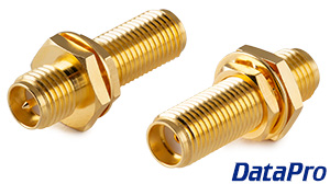
Panel Mount RP-SMA to SMA Coupler MF
waxen halo
I know it's pretty common to make a custom power supply frontend for a computer PSU. I was looking at doing the same, but now I'm exploring doing it with a USB PD supply. The thing with the computer PSU is there are already nicely defined 12v, 5v and 3.3v rails.. but for PD I'd have to break out the rails myself from a variable voltage source. Is this a terrible idea?
supple pollen
You only get one rail at a time, are you thinking of having different connectors for each rail and switching between them so only one set of connectors is powered at a time, or what?
waxen halo
I was thinking I'd request the highest voltage I could and step down
supple pollen
That seems reasonable, could be a compact unit. But if you're already (re)regulating the power, there's not a lot of advantage to starting with USB PD, other than pre-built converters so you don't have to deal with mains.
waxen halo
Well the plan is to use the same USB connection to passthrough data lines to connected devices so the custom supply can also act as a programmer
supple pollen
Interesting use case
 latent jungle
That sounds like two completely different goals.
waxen halo
latent jungle
That sounds like two completely different goals.
Doesn't it describe how most dev boards operate? Plug it into your computer and you get 500ma and a programmer.
latent jungle
What do dev boards have to do with PC power supplies?
waxen halo
The PC power supply is just the potential supply to the custom front end
latent jungle
Okay. Well. USB-PD is negoitated with its own set of signals. So, "passing the data signals" is just a matter of routing D+/D- the board regardless of supply design.
Stepping down an input supply down to multiple rails is pretty much what every device does.
Maybe you can get inspiration from this unique USB Hub design: https://www.crowdsupply.com/aerio-solutions-sas/usb-insight-hub
 ripe dawn
if I have some buck converters like this (with a 2A limit) and need more current (e.g. 5A), can I just wire three of these in parallel? or is that going to cause all sorts of issues?
 supple pollen
It's going to cause all sorts of issues. You're much better off getting a buck converter capable of your intended current draw (Pololu offers some nice ones).
ripe dawn
ah dang 😔 the prices and sizes definitely don't seem to scale linearly with output power 😭
latent jungle
Power output doesn't scale linearly with difficulty.
 inland jungle
they have this kind:
https://www.amazon.com/10A-5V-Converter-Waterproof-Transformer/dp/B09SD7P92Z/

10A 50W DC-DC 12V 24V to 5V Converter Buck Regulator Waterproof Power Supply Voltage Transformer Module
assuming you want a fixed 5V output
ripe dawn
interesting, I see it says
Input range: DC 10V-35V
Input voltage: DC 12V/24V
the first line seems to suggest anything in the 10-35V range, but the second suggests it needs to be 12 or 24V?
Other spots also say things like 12V 24V to 5V 10A Converter Buck Regulator
sacred badger
Itd likely take anything from 10-24v and regulate it down to 5v
 gritty sigil
anyone here ever got a defective usb-c socket on esp32 feather v2? I think I have this here. I have to put pressure with my thumb on the usb-cable for it to make contact with the pcb inside, the minute I stop applying the pressure needed and let the usb-c cable sit on its own in the socket it disconnects. I've tried 3 cables. I'm about to contact my reseller and ask them for a replacement, but curious if anyone here ever had that
unique patio
gritty sigil
anyone here ever got a defective usb-c socket on esp32 feather v2? I think I hav...
This sounds like a soldering issue. We would be interested in the work order number that is on the bag it came on, if you still have that. Where did you buy it from?
 worldly schooner
It could also be mechanical damage. I can't speak for USB-C, but I've had similar experiences with older USB ports before, and a slight adjustment of the retaining clips helped it stay connected.
gritty sigil
I bought them from one of the french resellers of adafruit, gotronic. I've sent an email to them in case... Not sure how to solve this, if it can be solved at all
unique patio
gritty sigil
I bought them from one of the french resellers of adafruit, gotronic. I've sent ...
I think ideally they would replace it, but you can write to our support folks too if that is not working. Ping me later for more details if their answer doesn't help.
gritty sigil
one reason I bought from them is because they accepted to do the solder job for me. Darn. They did a splandid job, too. They must be so disapointed
also because by avoiding shipping from the US I avoid custom fees and probably big shipping fees :/
worldly schooner
@gritty sigil can you take a picture of the connector in question? If you can get a decent shot of the solder joints, maybe we can narrow down the issue.
gritty sigil
I could try. I'm blind but I can try to take a picture of the board itself. Should I try to picture it from above, or rather point the usb socket to the camera to do this, so holding it vertically?
unique patio
gritty sigil
I could try. I'm blind but I can try to take a picture of the board itself. Shou...
Just from above. Did they solder headers on for you? Is that the only thing they did?
But I would say work with them, since if we did a replacement it would not have headers
gritty sigil
yeah they soldered headers on, that's all they did
so I reckon the usb port was most likely already damaged before they worked on it. I doubt that soldering in headers could have damaged the usb-c but what'd I know
unique patio
The USB port connection can also get damaged if something pulls hard sideways on the USB cord while it's plugged in. It has to be a pretty strong force, but we've seen that before. We've also seen inadequate soldering.
In any case, let us know what the distributor says.
gritty sigil
yep will do 🙂 at the very least I know I was not the one to damage it, because the first time I plugged it in it spewed a bunch of errors at me already
I mean I suppose I can always power it via the 5v pin, but... Meh. That means I need to connect it right away to an sbc in order to use it properly. Not to mention I'm not sure if I can flash anything on it using uart1 ?
gritty sigil
I also see no way of working around the current issue and get a functioning usb-c port. At least I contacted the seller soon as I noticed the problem, which lucky for me was on the same day as I received the order
gritty sigil
yeah I guess we have to forget the picture idea... I tried at least 30 times with AI to guide me and I just couldn't get the right angle or focus or whatever to show the joints
unless there's a way to do voice chat here somehow and I could use the camera on call to show it live? I don't know
unique patio
gritty sigil
yeah I guess we have to forget the picture idea... I tried at least 30 times wit...
I'm not sure it's worth it. In order to see an issue we would need a high-magnification picture of the solder joints on the USB jack. Does it feel wiggly?
gritty sigil
nop, not one bit wiggly
but inside it the usb-c plug of my cable is wiggly
the cable plugs get to wiggle about in the socket, basically. One tiny little wrong bump and it disconnects if by miracle it stuck on when I plugged it in. But most of the time I have to apply some force on where the plug meets the socket for it to connect
unique patio
gritty sigil
but inside it the usb-c plug of my cable is wiggly
That's true of my good plugs as well. It may be that the fingers inside the jack got damaged somehow.
gritty sigil
if that is it then I reckon the only fix is to solder on a new usb-c socket, right?
that's assuming of course that one would have what is needed to even do that... Board swap's more likely in my case seeing my disability
gritty sigil
so I've gotten a friend to take a video of the board when I'm trying to demonstrate the issue. I get that there should be some wiggling going on, but that much? Suspicious to me. Also took a picture of the board
hopefully that showcase the problem good enough... Sorry for the awful quality but couldn't do better
 unique patio
gritty sigil
hopefully that showcase the problem good enough... Sorry for the awful quality b...
unique patio
gritty sigil
hopefully that showcase the problem good enough... Sorry for the awful quality b...
nothing obvious, but I hope the distributor is able to help. Otherwise you can post in https://forums.adafruit.com which is the official channel for replacements.
gritty sigil
yeah. But do we at least agree on the fact it should have a bit of wiggle room but not SO much?
or am I insane?
because right now if I plug it in, a lot of the time my pc just doesn't enumerate it. As in, it's not even trying to. I might get it enumerated sometimes byt it's very rare. If I put it on my esd mat when it is connected, poof it's gone
unique patio
gritty sigil
or am I insane?
I think it is broken, somehow. I am not sure how. It could be the soldering, or it could be inside the jack. Either way, it deserves replacement. This is not common: there is something wrong with this particular one.
gritty sigil
it's a relief to know that I wasn't imagining it 😄
thanks for the help, really appreciate it. I'm very curious what the folks at gotronic will say about this one. I've sent them the video and picture, so they can be sure I'm not making it up 😉
ripe dawn
I would check that it's not the cable that's the loose/wiggly part (I've had that issue in the past). Also personally I'd buy a new one of these boards before attempting to solder a new connector on it 😅
 lilac pecan
was no one gonna tell me that the nrf52840 would struggle with HD video?
 knotty tiger
gritty sigil
because right now if I plug it in, a lot of the time my pc just doesn't enumerat...
knotty tiger
gritty sigil
because right now if I plug it in, a lot of the time my pc just doesn't enumerat...
you're putting a live bare PCB on a ESD mat? maybe don't do that. it might be conductive enough to short things out, or at least make them misbehave
lilac pecan
is the m4 express still top of the line for feather form compute?
unique patio
lilac pecan
is the m4 express still top of the line for feather form compute?
The Espressif chips can have more RAM (in the form of PSRAM). THere will be a Feather RP2350, of course. Depends on the capabilities and capacities you want
lilac pecan
hmm, i want to make a action cam esque thing, considering teensy, or raspberry pi pico idk, but I might just continue with my nrf52840 sense in low res
unique patio
lilac pecan
hmm, i want to make a action cam esque thing, considering teensy, or raspberry p...
do you want to record video? That's a tall order. There is native camera support on various Espressif builds: https://learn.adafruit.com/search?q=camera%2520circuitpython
lilac pecan
unique patio
do you want to record video? That's a tall order. There is native camera support...
yes, I would also like video stabilization, but maybe after the fact because extra processing, since I have sensors from nrf; but that would also require writing the sensor data, and idk if that would bottleneck there
and the memento is a little big for my goal
 hasty solar
trying to troubleshoot some indicator LEDs in a circuit driving a relay. subset of the current schematic attached - left LED indicates "voltage supplied from timer pin," right LED indicates "transistor closed and supplying power to relay," but the issue i'm hitting is that the voltage sent to the relay is dropping due to the current splitting off to supply the LEDs, and it doesn't end up high enough to activate the relay. the only way i can see to increase the voltage back toward Vcc is to reduce the resistance toward the coil, but that puts the current over the rated current for my relay. am i missing a better way to set up these indicator LEDs?

i could just throw more transistors at it ig
knotty tiger
hasty solar
trying to troubleshoot some indicator LEDs in a circuit driving a relay. subset ...
what's driving the transistor base?
hasty solar
op-amp wired up as a voltage comparator
hasty solar
hmm, seems like the op-amp might be sinking the voltage somehow. increasing resistance on the op-amp's inputs reduces the voltage drop i'm seeing in the output circuit
specifically it looks like the ratio between the resistance on the input and the resistance on the output was causing issues. putting 100k ohms on the inputs and 1k ohms on the output virtually eliminated the voltage drop across the transistor
supple pollen
hasty solar
trying to troubleshoot some indicator LEDs in a circuit driving a relay. subset ...
My guess would be the current is dropping due to the 100Ω series resistor
hasty solar
sure, but the current dropping is what I want - it keeps it within spec for the relay. the trouble was that the voltage was dropping.
sacred badger
anyone experienced with re-using laptop parts -- namely keyboard/touchpad
if so, can we agree Elan is a crappy corporation
i'd love to reuse the gigantic touchpad of the Dell XPS 9500/9700, tho idk if i'm missing something such as I2C drivers being built in to the BIOS, or it totally not being plug n play with an FT260, requiring some sort of further driver to init it and present it's descriptors to the OS
furthest I got was i2cdetect -- finding address 2c -- then i2cdump the address, first 2 words showing 00 00 -- dump again, everything FF FF or 00 00 -- i assume it expects some sort of write to function, but i'm not a software guy
sacred badger
unique patio
or how about https://www.datapro.net/products/panel-mount-rp-sma-to-sma-coupler-...
$35 each is steep -- would need 4, and $140 is outrageous. $60 more and I could finally FPV my drone
wonder just how difficult it is to assemble some RG174 W.fl or MHF4 pigtails and some elongated RP-SMA bulkheads
gritty sigil
knotty tiger
you're putting a live bare PCB on a ESD mat? maybe don't do that. it might be co...
I mean I posted a video that shows that even when it's not resting on any surface it misbehaves 🙂 I have to hold the usb-c socket against the cable otherwise things go crazy
gritty sigil
ripe dawn
I would check that it's not the cable that's the loose/wiggly part (I've had tha...
I've tried a good 4 cables by now, so it's definitely not the cable. As for soldering anything, out of the question for me since I'm blind, either way
supple pollen
hasty solar
sure, but the current dropping is what I want - it keeps it within spec for the ...
That can be a bit of a balancing act, but it's a consequence of Ohm's law: changing the voltage changes the current, and vice versa.
supple pollen
sacred badger
i'd love to reuse the gigantic touchpad of the Dell XPS 9500/9700, tho idk if i'...
Dell is notorious for using nonstandard cost-optimized parts for which drivers and documentation are difficult to impossible to find. The laptop parts I most often re-use are the displays, as they're generally the most valuable remaining part, after the other parts have become less relevant.
hasty solar
supple pollen
That can be a bit of a balancing act, but it's a consequence of Ohm's law: chan...
what determines whether the current or voltage changes? i was picturing current being the only thing that changes, given a constant voltage source and varying resistance
supple pollen
The difference is that the voltage is now split across the 100Ω resistor and the relay coil (possibly in parallel with some LEDs)
hasty solar
oh this simplifies things dramatically actually. i had the coil resistance set to 100 ohms in the simulator but the datasheet puts it at 720 ohms at ambient temperature. makes the voltage/current swings much less dramatic.
 coarse lark
does anyone know of a good NRF52840 module thats similar to the ESP WROOM's or what the itsy bitsy uses?
 unique patio
coarse lark
does anyone know of a good NRF52840 module thats similar to the ESP WROOM's or w...
unique patio
coarse lark
does anyone know of a good NRF52840 module thats similar to the ESP WROOM's or w...
do you want the module only? You can get the RAYTAC module by itself. We sell the Feather one separately: https://www.adafruit.com/product/4078

If you have a custom PCB design and you'd like to add a little Bluetooth Low Energy, this module is ultra compact and easy to use. It contains a Nordic nRF52840 Cortex M4 chip that comes ...
and there are plenty of other distributors of the Raytac modules
coarse lark
unique patio
do you want the module only? You can get the RAYTAC module by itself. We sell th...
yeah thats what ive been lokking for, thanks
im looking into these modules for a future board im planning
another module i found was one made by minewsemi which also looked promising
coarse lark
ill look into these
 winter lake
Hello yall, I was wondering if someone could help me with an issue I'm having. Essentially I am trying to make a vaping device with adustable voltage based on an rpi pico, I achieved this through PWM, but the only problem is that the current the pico outputs is only 12mA whereas I need 1.5-3A of current. My current circuit is: 3.7V battery w/ 750 mAh capacity, this is connected to a 5V boost board that I use to power the pico (don't know it's current output, but it's sufficient enough to power the pico so take from that what you will), the pico then has PWM, and I also have an NTE2987 mos laying around but I am confused on how to implement it. Sorry for the long paragraph but I've been asking all the AI's and searching all the forums to no avail.
supple pollen
NTE2968 maybe?
Normally for a MOSFET, you'd connect the source to ground, the drain to your load (and the other end of your load to its power supply), and the gate to a GPIO pin. Unfortunately, the Pico only produces a 3.3V output, which is insufficient to drive that MOSFET into sufficient conduction. You'll probably need either a different MOSFET that can be controlled with such a low gate voltage, or a bipolar transistor (along with a base current limiting resistor).
sacred badger
supple pollen
Dell is notorious for using nonstandard cost-optimized parts for which drivers a...
i mean, i did manage to externalize a 7370 3200x1800 touchscreen.. given the touch controller is USB based
i can tell the touchpad uses both I2C and PS/2, along with im guessing palm detect and an i2c interrupt
though, there may be a pullup resistor needed on some particular pin

maybe on TP_LOCK, PTP_DIS#, or even TP WAKE need those pull up/down resistors
which, to me, it should work with PS/2 alone, though I went down a BIOS disassembly (non-dell, HP) rabbit hole and couldn't really find i2c touchpad drivers, but did see touchscreen relevant things, along with various i2c drivers
sacred badger
thank heavens for thetechstall for schematics..
 sweet cairn
Something I'm curious about - why have 'Do Not Place' footprints like R9 here?
Is it a case of 'I might need it later but I'm not sure so I will leave space for it'?
 sacred badger
you ever see PCBs with pads placed, but no components?
gritty sigil
unique patio
I think it is broken, somehow. I am not sure how. It could be the soldering, or ...
just wanted to let you know gotronic replied and sent a replacement, free of charge, and let me keep the original defective board at the same time. Maybe I can still make something with it, who knows? Using the 5v vbus gpio and programming via uart1 for example, rather than uart0
unique patio
gritty sigil
just wanted to let you know gotronic replied and sent a replacement, free of cha...
Glad to hear!
sacred badger
dan, i think i'll go with some flange mount rp-sma connectors, hopefully they're small enough for my use-case.
gritty sigil
is my idea of programming over uart1 doable? I think so, but not sure. Like for example if I connect a ftdi usb to ttl adapter on uart1 pins, I can just specify this in arduino ide for flashing,? I don't think uart0 is special in this regard
sacred badger
i presume uart0 is for exactly that purpose
gritty sigil
yes. But it's broken on this board they let me keep
unique patio
gritty sigil
is my idea of programming over uart1 doable? I think so, but not sure. Like for ...
uart0 pins are also broken besides the USB jack? I would say the amount of time you are going to spend on this is not worth your time.
gritty sigil
no no they are not broken. But I thought uart0 was accessed via usb-c only
sacred badger
i assume theres some sort of usb ~> serial converter
would cutting this like it's cropped be ok?
 unique patio
sacred badger
would cutting this like it's cropped be ok?
unique patio
sacred badger
would cutting this like it's cropped be ok?
that should be ok if necessary
sacred badger
 unique patio
gritty sigil
no no they are not broken. But I thought uart0 was accessed via usb-c only
unique patio
gritty sigil
no no they are not broken. But I thought uart0 was accessed via usb-c only
there are no pads that are easy to get to, right
sweet cairn
sacred badger
you ever see PCBs with pads placed, but no components?
No actually 😅
worldly schooner
sweet cairn
Something I'm curious about - why have 'Do Not Place' footprints like R9 here?
...
It looks like a pad meant for custom filter adjustments. I can’t say exactly how it should be used, but I could see someone using it to adjust the band or add attenuation?
sweet cairn
worldly schooner
It looks like a pad meant for custom filter adjustments. I can’t say exactly how...
I think I understand, but still not fully sure 😅
Not sure if they check mentions but maybe @floral viper can help, they designed this revision of the adafruit macropad I think
 floral viper
sweet cairn
I think I understand, but still not fully sure 😅
Not sure if they check mentio...
floral viper
sweet cairn
I think I understand, but still not fully sure 😅
Not sure if they check mentio...
i actually didn't design it, i just posted the files 🙂 this would be a great question to post for AAE though!
knotty tiger
yeah, it does kind look like a place to adjust the input filter to the amp without revising the board
sweet cairn
floral viper
i actually didn't design it, i just posted the files 🙂 this would be a great qu...
Oh I see, apologies for the ping then 😅
I've already asked questions related to this a bunch of times but I haven't really fully understood. Hope it will be ok if I ask there
sweet cairn
knotty tiger
yeah, it does kind look like a place to adjust the input filter to the amp witho...
Got it, so it'd be another capacitor then right?
knotty tiger
sweet cairn
Got it, so it'd be another capacitor then right?
could be a resistor or capacitor; not sure what makes the most sense here. i'm kind of rusty on filter fundamentals at the moment. basically, if the filter doesn't behave as expected, they can add a part there by reprogramming the pick-and-place without having to revise the board (and order a new batch)
sweet cairn
knotty tiger
could be a resistor or capacitor; not sure what makes the most sense here. i'm k...
Makes sense. Does make it difficult for me to reproduce if they fitted it out on a production model but not on the schematic lol
knotty tiger
sweet cairn
Makes sense. Does make it difficult for me to reproduce if they fitted it out on...
yeah, that's plausible. i think back-annotating a schematic for a last-minute engineering change doesn't always happen (in general, not just at Adafruit), and even if it does, the published version might not get the update until later (if at all)
sweet cairn
knotty tiger
yeah, that's plausible. i think back-annotating a schematic for a last-minute en...
That's a bit of what happened here actually!
Not sure if it's relevant info but the original Amp IC used in the Macropad got discontinued so they had to switch to a different one, but the schematics weren't updated. Thankfully adafruit and its members on this server were kind enough to help out
Anyhow, I'll get a breadboard and the datasheet and start experimenting stuff until it works ig.
I had made a circuit design based on the amp's datasheet but that didn't work and I've been unable to figure out why, so looking to adafruit's board for reference
supple pollen
How didn't it work? Output too quiet? Output distorted? No output? Flames?
sweet cairn
supple pollen
How didn't it work? Output too quiet? Output distorted? No output? Flames?
There was no buzzer output. Based on what I could make out with some limited testing with a multimeter, the buzzer wasn't receiving any power, and I think amp IC wasn't either, not sure though it's been a while. And I am not sure if my testing was accurate either, so will be breadboarding my original design too
This is my implementation. You might remember having seen it since you have helped me out quite a bit with it in the past 😅
 supple pollen
Yeah, that does look familiar.
worldly schooner
What is the purpose of the caps to ground on the speaker side of the amp? oh I found the amplifier you referenced.
Also, why are there polarized caps on the input side?
sweet cairn
worldly schooner
Also, why are there polarized caps on the input side?
Datasheet had mentioned using tantalum caps for better performance so went ahead with it. I didn't really have to care about cost or practicality on this project and so just went ahead with whatever seemed fancy 😅
gritty sigil
unique patio
there are no pads that are easy to get to, right
indeed no. I just had a friend checking over https://github.com/adafruit/Adafruit-ESP32-Feather-V2-PCB and uart0 is not exposed anywhere else than usb-c

GitHub
PCB files for the Adafruit ESP32 Feather V2. Contribute to adafruit/Adafruit-ESP32-Feather-V2-PCB development by creating an account on GitHub.
I tried to get a basic sketch with OTA going, but the tiniest shake of my finger holding down the usb-c cable into the socket would cause it to fail
 rancid lagoon
Don’t know where to ask so i’ll ask here, could a pico do 1.8v I2C
unique patio
rancid lagoon
Don’t know where to ask so i’ll ask here, could a pico do 1.8v I2C
It will run at 1.8v if you power it at VSYS with 1.8v.
an nrf52840 is more flexible. you can power it at a higher voltage but set its pins to use a lower voltage
rancid lagoon
Then i’ll use a level shifter
sacred badger
sweet cairn
Anyhow, I'll get a breadboard and the datasheet and start experimenting stuff un...
slippery slope…

before long youll be modding aliexpress chinesium
 sacred badger
THERES A FREAKIN STRING TO SEPARATE LCD FROM BACK?!?
 supple pollen
Now THAT's a nice touch!
ripe dawn
well that would certainly up the repairability score!
sacred badger
dell xps 13 9350 btw
 rich sorrel
Hey are there any footprint files for the Feather RP2040? I found the PCB files but I'm looking for a footprint I can use to attach it to another board, and I'd like it to be more accurate than just using two header components to simulate it.
worldly schooner
rich sorrel
Hey are there any footprint files for the Feather RP2040? I found the PCB files ...
What software are you using? I believe there exists a generic Adafruit_Feather footprint for KiCAD in the Module folder.
rich sorrel
worldly schooner
What software are you using? I believe there exists a generic Adafruit_Feather f...
KiCad, I couldn't find it but I'll check again
rich sorrel
worldly schooner
What software are you using? I believe there exists a generic Adafruit_Feather f...
Ah, I am just an idiot, and found it immediately. Thank you for the help.
worldly schooner
rich sorrel
Ah, I am just an idiot, and found it immediately. Thank you for the help.
Don’t beat yourself up, there are a lot of parts in a lot of folders and it’s easy to miss haha
gritty sigil
well I am either cursed or I use a cable that displeases the feather for whatever reason. Absolutely insane! All of my cables are the same, I've always used those before, the 5a one meter long cable from adafruit. I have 6 of them. My new esp32 feather v2 has exactly the same issue. I've managed to flash esphome on it by being extremely careful and avoiding touching the breadboard on which it is connected, otherwise instant disconnect
either the cables are all wrong, or both of the feather boards are broken in exactly the same way, or... I honestly have no clue what's going on
never seen something like this, pun intended 😉
right. Just placing a finger on the breadboard is enough to disconnect the whole thing. Holy wow
gotronic assured me they tested the board before sending it over and I see no reason they would have lied about that. Plus I don't believe that getting two defective boards in a row is this common, let alone two with exactly the same issue
so if anyone has any ideas here I'm all for that, because I have no clue what to even do anymore
 hushed ermine
maybe you are extremely conductive
gritty sigil
heh, maybe? But I have an esd mat, the dissipative kind, and I ground myself on it using a wristband. My mat has a connector for the wristband
and I make a point to never touch a pcb without wearing it
unique patio
gritty sigil
right. Just placing a finger on the breadboard is enough to disconnect the whole...
so you are not touching the USB cable itself, just the breadboard?
If you put your finger on the USB jack on the feather, with nothing plugged in, does it feel like it's wiggling?
gritty sigil
nop it's stable
and yes only the breadboard. I can only assume by touching the breadboard, I moved it a few milimeters and poof it went
fwiw the usb cables I use are these ones here https://www.adafruit.com/product/4199

As technology changes and adapts, so does Adafruit! Rather than the regular USB A, this cable has USB C to USB C plugs!USB C is the latest industry-standard connector for ...
gritty sigil
so I tried the usb cable that came with my anker battery just for the giggles. Same issue
so that means the adafruit cables are not the problem
unique patio
gritty sigil
so that means the adafruit cables are not the problem
does it feel like the plug is seated all the way in to the socket? It is very strange. Did Gotronic send you a new board and you still have the old one?
I have one of these, and it's fine. Do you have the original bag with the work order number on it?
The still photo is very dark, but I was enable to enhance it. I don't see anything wrong. However, it is very low resolution. If the original is higher resolution, could you post that?
also does it make any difference if you turn the USB plug upside down, since it's reversible?
One theory is that one of your cable plugs may be damaged, and because of that it's damaging the socket in these boards. But then it would damage other board sockets too. If you are not seeing that, then that would eliminate that theory.
gritty sigil
hm yeah I know the still is very low resolution. I had to do it with the help of a friend, they literally took a screenshot of the video call we were in while we were trying to check out the board for issues. I still have the original board, gotronic let me keep it instead of making me go through the hassle of return and all that.
As for the usb cables, I can definitely tell you that I used it with other boards, including seeduino xiao, and even a zoom f3 field recorder, with no problem. I can try to reverse the cable and see if it does anything, too.
I needed to be guided to be sure the still would show the board properly, so kind of why I couldn't take a high resolution picture at the same time since I was in a video call
the easieest way I can reproduce this now is just lifting the breadboard away from the desk, which forces the usb cable to angle up or down, it's game over
I just tried another cable, usb-a to usb-c this time around. Didn't expect different, but tried regardless. So that's 8 problematic cables. I reckon by now it's far more likely to be the board having a problem, as insane as it sounds
gritty sigil
I so wish I was tiny enough to explore the usb socket lol
 dim sapphire
I’m looking at the page for the esp32 feather v2 (https://www.adafruit.com/product/5400?gad_source=1&gclid=EAIaIQobChMI3YGv6oK-iAMV9h-tBh0BFDdTEAAYASAAEgJkiPD_BwE) and it says there’s two i2c ports but “only one is configured by default in the Feather Arduino IDE support”… can anybody tell me the implications of this? Would I be able to configure the chip to use both i2c ports for peripherals, using either arduino or circuitpython?

One of our star Feathers is the Adafruit HUZZAH32 ESP32 Feather - with the fabulous ESP32 WROOM module on there, it makes quick work of WiFi and Bluetooth projects that take advantage of ...
gritty sigil
I believe so, but don't quote me on it. I think pinmux lets you configure any gpio as i2c or uart or whatever on the board, if I'm not mistaken. Plus, the pinout on the adafruit guide for the feather v2 does talk about i2c afaik
as for how to configure the pins, not sure about that myself given I couldn't even really get started with mine as I keep having issues
 regal crater
Good Evening/Morning All! I'm new to h/w coming from a software design background and I'm having heaps of fun! I've gotten stuck into kicad and I was hoping to work out what might go into getting the ADA1385 UBEC DC/DC onto my pcb instead of adding a couple of plugs and wiring in and out.
I can see the active chip for v in -> v out is an MP2307 but I'm struggling to work out what's on the rest of the device being new to h/w and all. I was planning on making a custom symbol and step file eventually as I haven't found one
https://www.adafruit.com/product/1385 I was hoping for some help working out what else is on it

Your power supply problems just got SOLVED! This little circuit board may look tiny but inside is a high efficiency DC/DC step-down converter which can output up to 3 Amp at 5V without the ...


 supple pollen
regal crater
Good Evening/Morning All! I'm new to h/w coming from a software design backgroun...
supple pollen
regal crater
Good Evening/Morning All! I'm new to h/w coming from a software design backgroun...
My first stop when investigating a new chip is to go to its manufacturer's site. Normally there will be a data sheet which will include a description and some example circuits. Often there will be an evaluation board too. While you don't need to buy the evaluation board, the manufacturer's description generally includes a full PCB layout, parts list, and explanation.
In this case: https://www.monolithicpower.com/en/mp2307.html
In this case, the MP2307 is an older chip, not recommended for new designs, so you might consider the updated MP2393 https://www.monolithicpower.com/en/mp2393.html if you're designing your own board.
unique patio
gritty sigil
I so wish I was tiny enough to explore the usb socket lol
I discussed your USB jack problem internally. We have no previous record of such a problem with the USB jacks. This is the same jack we use on many, many other boards. We are willing to replace the board from Adafruit directly, but it will not have soldered headers. You could also ask Gotronics to test some of their stock and see if it has the problem. (Maybe they are testing the board after soldering on the headers, and by chance they are testing with a cable that damages the plug. But that is an unlikely explanation.)
Perhaps it's worth giving one of the boards to a friend for further trials.
If you open a thread in our Forums, say in, https://forums.adafruit.com/viewforum.php?f=57, we can get you in contact with Adafruit support for a direct replacement and further discussion.
gritty sigil
unique patio
I discussed your USB jack problem internally. We have no previous record of such...
I thought of them damaging the port too, I don't see what else it could have been, even if it's unlikely. I have no more ideas right now. I'm guessing a further step might be to examine the port via a microscope or something, but I don't know for sure. I wouldn't mind talking of this further in forum, but having a replacement without headers would be useless to me. I've got noone close to here who can solder, and that's the entire reason why I asked gotronic to solder this in for me
I even tried with a psu from anker just to see if it would behave differently than with my pc, but nop. Lift the breadboard away from my desk a little and the esp32 instantly stops responding to ping, which suggests it lost power
unique patio
gritty sigil
I thought of them damaging the port too, I don't see what else it could have bee...
I discovered we do sell it with headers: https://www.adafruit.com/product/5900
gritty sigil
do we at least know if there'd be any custom fees?
unique patio
I have no idea. You'd have to ask support that question.
gritty sigil
would make sense there is, though
unique patio
It depends on your timelines. You could mail one to someone to check it, or mail it back to gotronics. Gotronics could order some headered ones on its next distributor order.
But I think they need to check their stock, and check one of the ones they did for you.
If they have a batch of bad ones, they need to know that. Or they need to know it got damaged later.
gritty sigil
ironically I asked them if they could get me id 5900. They said they could but it would take several weeks for it to get to them and then for them to send it over, so we settled on them soldering in headers for 5400
yeah adafruit would have custom fees to france, likely
VAT 20% of total cost
there's a ddp option for dhl express, that said. Might cost more shipping but honestly if it avoids the stress and hasle of duty tax after
gritty sigil
I'm not sure what to post in forum exactly though? But I suppose I could ask for a 5900 as replacement, because really no headers in is a problem... But also 44 usd of shipping with dhl express or 20 usd of shipping with usps is kind of ouch
unique patio
gritty sigil
ironically I asked them if they could get me id 5900. They said they could but i...
You can have that conversation with support by email. The only reason to post in the forums is to establish a thread there where I authorize a replacement.
that is our standard procedure
gritty sigil
I see. I'm still unsure tough given it would cost me $44 usd shipping with dhl express (probably ddp but unsure as well about that), or $20 usd with usps and who knows how much custom fees... Ugh.
unique patio
no, it would not cost you. We are replacing it.
gritty sigil
ahh so free shipping too... Aside from customs I guess, cause adafruit has no control over this
unique patio
there may be some way around that, since it's a warranty replacement. Support would know
gritty sigil
alright. So what should I write in the email to support essentially?
 fervent lance
I have a problem. Basically I made a riser of s camera module to extend it out from the main board. The thing does not work. Connections are fine. What worries me is that it may be something from signal integrity, and if that's the case, I really don't know how to fix it without lots of trial and error
unique patio
open a thread in the forum. Post the link to the thread here and ping me. I will answer, authorize a replacement, and then you will email support.
gritty sigil
okay. Gosh, sorry for all the questions, I'm a bit of a mess after two failed boards. I'll also try and do my best to arrange shipping back to gotronic at the same time. They were really nice to send one over without me having to return the first board, because returning for me is a nightmare. The post office opens at ridiculous hours where everyone works and closes exactly when people get off work, and the entire thing's touchscreen driven. And the staff is heavy handed with discrimination and telling me to bring a friend along to help because they have better things to do
unique patio
I am sorry you have to put up with that. We could veer off into disability rights but we're talking different countries here.
I agree, our replacement procedure is a bit unintiuitive. discord is an unofficial support channel; the forums are the official channel, so we do stuff like that through the forums
gritty sigil
yeah, figured it was something like that. I'm a bit stressed and confused also honestly so it didn't help me catch up
unique patio
I have no idea what gotronics wants to do but a phone call or and email exchange may resolve that. I wonder if you can get a prepaid mailing label or something.
gritty sigil
yeah I'll ask them, worth a try
gritty sigil
I also tried to get the order number that was on the bag just in case, but I kept messing up with AI hallucinating things
 cold path
anyone skilled with PCBs have a question. Am just really starting to build and design them so my knowledge is very low, and learning a lot as I go.
I am making a PCB with a Pi Zero W mounted onto it. However, I want to have the SD card available in a different place than where it will be mounted. Can I put an SD reader on a different part of my board and run traces back to the Pi? But then, how would I connect the Pi to the traces? Would I then have to desolder the SD reader from the Pi and patch wire from the trace ends to the desoldered points on the Pi?
I know I could get an SD extender and run it over, but I am trying to do it as neatly (and cool) as possible!
If I am trying to do something stupid, please call me a dufus and point me in the right direction. 🙂
gritty sigil
okay posted topic asking for replacement but also recap of the whole deal, in case it ever affect others
while writing this I was thinking about soldering... Could that have damaged the pads of the usb-c jack ? I don't know enough about soldering and electronics over all to say, but it's a thought that came to my mind
 shy spear
Hi, Im posting today because after attempting to get feedback on r/PrintedCircuitBoard either no one responds or the mod gets mad at me for having to many tiny subcircuits... Is he in the right, I really dont know and am hoping for some honest feedback when it comes to my pcb design. Please let me know if im posting in the wrong channel or if there are other discords more suited to pcb design review.

 supple pollen
gritty sigil
okay. Gosh, sorry for all the questions, I'm a bit of a mess after two failed bo...
supple pollen
gritty sigil
okay. Gosh, sorry for all the questions, I'm a bit of a mess after two failed bo...
It might be worth trying a cord and board and firmly pushing the USB connector into place. Some of them seem to seat, but just barely make connection, but some more pressure causes them to pop in another millimeter or so and provide a solid connection.
supple pollen
shy spear
Hi, Im posting today because after attempting to get feedback on r/PrintedCircui...
You're trying to parallel two buck converters, that is not a good idea. I'm guessing the motors are servos – if so, a 3.3V signal should control them directly, no level shifter needed. And the commenter is right, it is hard to follow the circuitry with everything split up like that.
shy spear
supple pollen
You're trying to parallel two buck converters, that is not a good idea. I'm gue...
So to what degree should I have my subcircuits, if possible an example would be great. I will look into either an IC buck converter or just a slightly bigger buck converter module that can handle all the 10 amps that I need (realistically never going over 6). I thought I might as well use the level shifter for the servos because the motor controller requires 5v signal for control. Other than those errors are my resistor and capacitor placement good?
shy spear
supple pollen
You're trying to parallel two buck converters, that is not a good idea. I'm gue...
I would also like to thank you for a very nice and informative reply, im relatively new to pcb design and my only previous experience with it is from a short segment of highschool.
supple pollen
How to divide things into subcircuits is a matter of taste, but if a couple of devices mostly connect to each other, I just put them next to each other and connect them. Note that 10A is a lot for a PCB trace, you'll want wide traces, and possibly omit soldermask and add solder or even a bus wire to improve their current carrying capability.
worldly schooner
cold path
anyone skilled with PCBs have a question. Am just really starting to build and d...
I can’t speak for the zero W as I don’t have one on hand to compare, but the 2W has test pads underneath that allow access to the sd card port. The proper way to connect to them would be with pogo pins, but you’d need some means of ensuring secure mechanical mounting to the pcb for that to work.
 unique patio
gritty sigil
while writing this I was thinking about soldering... Could that have damaged the...
unique patio
gritty sigil
while writing this I was thinking about soldering... Could that have damaged the...
If the soldering was done with any skill, it shouldn't make any difference. I do that kind of header soldering all the time. But to check for an issue, the board really needs to be inspected. An experienced friend would be able to tell and would be a neutral party, but that requires mailing one of the boards.
gritty sigil
supple pollen
It might be worth trying a cord and board and firmly pushing the USB connector i...
yeah I tried that tons of times. It's really going as deep as it can, pushing further just makes the usb jack even more mad and reconnects/disconnects tons of time
 obsidian dove
I'm using the matrix portal S3 with an Adafruit 64X64 RGB display. My text or bmps are always split in half, half on the upper and half on the lower of the display. I cannot figure out how to fix this. The board is already E addressed for this display, per Adafruit. I need help.
gritty sigil
unique patio
If the soldering was done with any skill, it shouldn't make any difference. I do...
aye, makes sense... Thanks so much for the help btw, appreciate it a lot
cold path
worldly schooner
I can’t speak for the zero W as I don’t have one on hand to compare, but the 2W ...
That's really useful thanks
 urban cypress
hello i have a power only type-c extension cable and i'm trying to convert it with a toggle switch.
thing is i can't seem to get any power from it i tried multiple type-c power sources.
i tried checking for continuity on red and black including flipping it over. it's ok too.


 urban cypress
ugh nevermind i found reference that these don't work on the raspberry pi 5 https://thepihut.com/products/usb-c-cable-with-switch. nor any other of my type c devices. shop i bought it from didn't have that notice but they were recommended for the raspberry pi.
 dry ember
does anyone know the exact connecter on the Lithium Ion Polymer Battery - 3.7v 1200mAh?
Attempting to order the corresponding jack on Digikey, can't tell which one it is for the life of me

Lithium-ion polymer (also known as 'lipo' or 'lipoly') batteries are thin, light, and powerful. The output ranges from 4.2V when completely charged to 3.7V. This battery has ...
i think this is the correct jack, but i might be completely off

DigiKey Electronics
Order today, ships today. S2B-PH-K-S – Connector Header Through Hole, Right Angle 2 position 0.079" (2.00mm) from JST Sales America Inc.. Pricing and Availability on millions of electronic components from Digi-Key Electronics.
rancid lagoon
they're https://adafru.it/1769 if it helps
 ornate carbon
Hi -- not to sure where to ask this. Anyway, does anyone know if this USB to Serial cable is 5V compliant? I.e. I know it sends 3.3 V logic, but if I feed it 5 V logic will I kill it? https://www.adafruit.com/product/954

The cable is easiest way ever to connect to your microcontroller/Raspberry Pi/WiFi router serial console port. Inside the big USB plug is a USB<->Serial conversion chip and at the end ...
(There's other USB to TTL things on the website that are explicitly 5 V compliant, but the way this is broken out is particularly convenient)
latent jungle
ornate carbon
Hi -- not to sure where to ask this. Anyway, does anyone know if this USB to Ser...
Based on this note, the corresponding data sheet says RXD is 5V tolerant
After July 1, 2014 we changed to a violet body and the PL2303TA chipset.

footnote 2
ornate carbon
latent jungle
Based on this note, the corresponding data sheet says RXD is 5V tolerant
> After...
Ah, I see there's this note: "As of Dec. 21, 2016 we will be shipping cables with SiLabs CP2102 chipset instead of Prolific." Looking at the CP2102 datasheet it lists 5.8 V on the absolute max on "any I/O" pin so it looks like it will be happy with 5 V.
latent jungle
lol. I remember seeing the second bullet point on the page, but I read it as "2006" not "2016. 🙂 Good catch.
 jade wedge
So, I want a switch to control power, which may be as high as 1A, but I want a small switch as it's a small board, so a 1A capable switch is out. Obviously, use the switch to control a MOSFET.
N channel, in enhancement mode so it's normally off, but a positive gate voltage turns it on.
The positive of my power source should connect to the Source pin, while my load connects to the Drain pin... Right?
Also, pin 2 is the Source, right?
 supple pollen
Nope, the positive of your power source should connect to one side of your load and one side of your switch. The other side of your load connects to the drain. The other side of your switch connects to the gate. The source connects to the negative of your power source.
Note you probably want a pull-down resistor from gate to source to turn off the MOSFET when the switch is off.
jade wedge
Figures I'd get it backwards. Also, I realized how I got mixed up. In collecting information one of the examples I was looking at had the configuration I described. It's for a P channel though.
Also the gate goes to ground instead.
So if I use a P channel instead, and ground out the gate, it should work how I originally was hoping, right? I think I'd rather switch the positive incoming line simply because this is hopefully going to be able to run off either battery or USB.
Let me hammer out a schematic
Is this better if I the switching done on the positive side, rather than negative/ground side?
 supple pollen
I usually switch the negative, but that works too
jade wedge
For some reason I feel more comfortable switching the positive. Conceptually I understand the effect will be the same either way, but disconnecting the positive just makes me feel better. Also there will be a battery as well, and that will be switched via the boost circuit, and therefore cutting off the battery's positive. So in my mind disconnecting both positives makes sense.
supple pollen
I don't understand what you mean by the battery and boost circuit and both positives, but that's okay I don't have to.
jade wedge
For battery power there's going to be a boost converter to bring it up to 5v, and the converter chip has its own enable pin that I plan to switch with the same switch (Double pole double throw switch). The converter chip will only disconnect from its input source. It can't disconnect the ground as that goes straight from the battery to the load.
supple pollen
If you can disable the converter, I don't see why you have to switch the load too.
jade wedge
Because it will be able to power from either battery or USB, and I don't want to have to unplug it to turn it off since it will also be able to charge.
The charger will of course be unaffected by the switch entirely.
You'll see when I get a proper design worked out.
Or I'll make a complete hash of things. One or the other. All part of learning.
supple pollen
Heh, the "all part of learning" is a bit I know well!
jade wedge
Heh. I assure you though, it all makes sense in my head.
Except for the FET part. Which should be straightened out now.
dry ember
anyone know if there is a datasheet or a footprint for the adafruit vibration sensor?

The "poor man's" accelerometer/motion sensor! These spring-vibration switches are medium sensitivity non-directional vibration induced trigger switches. Inside is a medium ...
supple pollen
Here's a similar part: https://soldered.com/productdata/2016/02/Soldered_SW-18020_datasheet.pdf
Here's another one that covers that specific part: https://www.robotpark.com/image/data/PRO/91469/shake_switch_sw180.pdf
 teal siren
Hello. I'm trying to figure out what I would need to get this to work: https://www.adafruit.com/product/413
what specific diode / transisitor / power supply configuration is correct? Any help is greatly appreciated 😉

Solenoids are basically electromagnets: they are made of a big coil of copper wire with an armature (a slug of metal) in the middle. When the coil is energized, the slug is pulled into the ...
is 1A power supply ok? do I need 5A ?
supple pollen
You'll want a 12VDC supply capable of at least 250mA. You can use a bipolar or MOSFET transistor to switch it, and a protection diode is a good idea.
1A is plenty
teal siren
is this a good transistor: https://www.adafruit.com/product/355

When you need to switch a lot of power, N-channel MOSFETs are best for the job. These FETs can switch over 60A and 30V and are TO-220 packages so they fit nicely into any breadboard or ...
supple pollen
Yes, that one is a good choice.
teal siren
thank you for your help. this is where I get confused. then I see something like this and don't get the difference: https://www.adafruit.com/product/976

Transistors are powerful little electronic switches, and when our little NPN transistors aren't power enough for your project, we have been known to use these beefy TIP120 Darlington ...
supple pollen
Those will work too. The first one is a MOSFET (which is controlled by voltage), the second one is bipolar (which is controlled by current). Both will work well in this application. Note that if you're controlling it with 3.3V logic, the MOSFET may not conduct fully and might generate some heat, but in this case (where it's only conducting 250mA to the solenoid), it should be fine.
teal siren
if you had to pick between the two which one would you suggest?
sacred badger
teal siren
if you had to pick between the two which one would you suggest?
sir, this is an Arby's
teal siren
Haha.. At this arby's, I don't want to make a mistake that would do more damage than necessary
supple pollen
It would depend on what I'm driving it with. I might opt for the TIP-120 as it can be driven easily from 5V or 3.3V logic, and is pretty robust.
Note that the MOSFET has a "parasitic" body diode that will act as a protection diode, but with either transistor, I would use a separate protection diode.
dry ember
I'm trying to power a NodeMCU ESP8266 board, which requires 4.5V~7V. My current plan was to use a 3.7 V LiPo battery (as it has a fantastic form factor), and a AP3602AKTR voltage regulator, which outputs 5V at 100mA. The problem is, while the operating current of the NodeMCU board is ~80mA, there is a massive current spike at startup up to 300mA.
Is there any easy way to deal with this current spike? Or is it far easier to just find a different battery?
inland jungle
MOSFET body diodes aren't quite the same as protection diodes, right? They're in a different place in the circuit...
 blissful frigate
dry ember
I'm trying to power a NodeMCU ESP8266 board, which requires 4.5V~7V. My current...
blissful frigate
dry ember
I'm trying to power a NodeMCU ESP8266 board, which requires 4.5V~7V. My current...
Even if the spike wasn't there your 100mA converter is likely gonna run very very hot
the datasheet does mention that it can take 250mA for 100ms
Efficiency isnt great either, below 60% if your battery is fully charged
supple pollen
inland jungle
MOSFET body diodes aren't quite the same as protection diodes, right? They're in...
You're right that they're not quite the same. There are a few different ways to place protection diodes.
rancid lagoon
dry ember
I'm trying to power a NodeMCU ESP8266 board, which requires 4.5V~7V. My current...
i'd get a different voltage booster that can give a bit more juice
dry ember
rancid lagoon
i'd get a different voltage booster that can give a bit more juice
yeah, looking at the LM5002
i don’t really understand how to set it up, but i guess i need to do some research on boost converters
dry ember
if anyone has any boost converter suggestions, lmk
worldly schooner
dry ember
I'm trying to power a NodeMCU ESP8266 board, which requires 4.5V~7V. My current...
The easier and possibly more efficient option would be to use a low-dropout regulator to feed the system directly via the 3v3 pin. Do note that this makes backpowering a concern, so I’d advise not connecting the board over usb while the battery is connected in this way.
rancid lagoon
what are the dimensions (mainly diameter) of the raspberry pi 5 RTC battery
latent jungle
dry ember
i don’t really understand how to set it up, but i guess i need to do some resear...
designing a SMPS is non-trivial, especially their PCB layout. It might be better to use an off-the-shelf module, depending on your load requirements.
if I need more than 10 W, I rarely do my own. And for less, I carefully follow the ref design, especially for PCB.
dry ember
thats what im currently doing
microchip was VERY kind and made example circuits, one of which was exactly what i need
latent jungle
again. the PCB layout is way more critical then the application circuit values
dry ember
currently looking at this guide by TI for pcb layout
any other suggestions of places i could find info about pcb design for boost convertors?
latent jungle
Now I’m confused. You said Microchip had good circuit examples and then you linked TI resources.
You need to follow the layout recommendations of the manufacturer for the SMPS controller.
dry ember
I was more looking at the general PCB layout tips in the TI resource, which seem to be consistent with other information I have found online about PCB design with Boost Convertors
Actually, thank you for pushing me to look, as I have now found an actual example layout for the MIC2288 which i could not find before
latent jungle
Unless you are a power converter expert, you should follow the manufacturer’s guidelines for the SMPS
Connecting components with thin traces isn’t going to turn out well
dry ember
Thanks for the advice. I'm still on the hunt for any information from Microchip about the MIC2288 other then an example PCB they put together a sheet on, and a data sheet that does not bring up PCB design.
 sick glacier
Hey guys, if anyone has any spare time and experience with single-cell LiPo charging, I was wondering if this schematic for a 2 amp charging circuit and power path would work. It uses a switch-mode battery charger instead of linear to handle the 2 amps properly. Thank you so much. Obviously, feel free to use it in your designs if it works lol (I don't take responsibility though, this is my first battery charging circuit)

 surreal tangle
sick glacier
Hey guys, if anyone has any spare time and experience with single-cell LiPo char...
surreal tangle
sick glacier
Hey guys, if anyone has any spare time and experience with single-cell LiPo char...
Is this LiPo a protected cell? If not, you may want to add a low voltage disconnect, otherwise your boost converter could drain the battery too low....
gritty sigil
@unique patio I got my replacement today 🙂 it is as we thought. id 5900's usb-c jack works perfectly fine. Whatever it is, the blame is with gotronic most likely when they soldered. I see no other possibility to be honest
now that I have a board that isn't defective on the usb-c jack front, there's somthing I noticed on the two others. It might be unrelated and not the cause, but... There is a miniscule crack at the back of each usb-c jack
the non defective board does not have it
unique patio
gritty sigil
now that I have a board that isn't defective on the usb-c jack front, there's so...
I'm glad you got a working one. When you say "crack", what to do you mean?
gritty sigil
the crack runs vertically from the back of the usb ports all the way down to where it meets the pcb. Almost like the usb jack has been split in two
it's large enough that I can comfortably move a fingernail along the length of the crack
I'm not exactly sure how to describe it
mmh
unique patio
there is a piece of plastic there. The same piece of plastic, I think, is also the middle "finger" that can be felt at the front of the jack. The contacts for the plug are on the lower half of the finger. So if the plastic finger is cracked at the back, I think that would explain the erratic operation
can you feel a crack on the finger?
there is no visible seam on the back that could turn into a crack
gritty sigil
I think so, yes. It's very hard to say. But there's something off with the back of those two usb-c ports compared to the functioning one
unique patio
it's hard to see how that would get cracked.If you have a bad USB-C cable, I could imagine pressing very hard might fracture the plastic. It could also be that there are multiple versions of this, and some of them are two-piece. But I don't see any like that on the boards I have.
gritty sigil
yeah. Like I said, random thing I've noticed
doesn't mean it's the reason for the failure
unique patio
Thanks very much for the observation. But it's an interesting correlation. We'll keep this in mind if we have other reports of flaky USB jacks.
gritty sigil
I'm not sure if it would be easier to get what I mean and if it's just a quirk that shouldn't matter with a video call somehow. If so I'd be happy to set that up with you, if you're interested. It's very hard to describe for me, and it is also rather difficult to take a picture that would show the issue on my own since I can't see
so maybe with a live showing you would have a better idea of what it might mean or not
unique patio
gritty sigil
I'm not sure if it would be easier to get what I mean and if it's just a quirk t...
sure, pick your video. you can DM me if you wish with that. Main thing is if you can get close enough. Also, put a bright light on it
gritty sigil
in case it matters, the serial numbers are as follows:
- good board: 5799004490
- bad board 1: 54B0006616
- bad board 2: 54B0007382
unique patio
The most interesting numbers are the work order numbers on the Adafruit fresh-from-the-factory bags. You may not have those for the Gotronics boards.
gritty sigil
probably not
I'll try and do my best to see if a video with a better resolution would capture what I mention. It'll take a bit of time since I'll have to find a way to take the video and have my friend look at it to see if it is visible or not, but I'll send it over in dm asap
unique patio
I thought you meant a video conference with me. That is OK too. If you are just recording a video, show the back and the front of the jack.
I was suggesting a DM in case you did not want to share the video conferencing link
ok to post recorded videos here in public
gritty sigil
oh. Huh. I misunderstood your previous message then, sorry! Since you mentioned taking your pick
yeah dm for conference sounds better to me since we can adjust the orientation and angle in realtime. I'm unsure if quality on something like google meet would be good enough for it?
gritty sigil
alright. You available atm?
unique patio
yes
unique patio
gritty sigil
alright. You available atm?
ok, great, thanks for the video!
Here are some of the terminal block products I was talking about. Unfortunately, they are relatively expensive, but they might be good for more secure connections when you are making a permanent project.
https://www.adafruit.com/product/3173
https://www.adafruit.com/product/2926
https://www.adafruit.com/product/5907
https://www.adafruit.com/product/5095
https://www.adafruit.com/product/5096
gritty sigil
unique patio
ok, great, thanks for the video!
Here are some of the terminal block products I ...
that sounds cool indeed. I guess for my use I'd take the second link then? The first one requires soldering but the second appears to be the equivalent if id 5900, that is comes pre-soldered, unless I misread
unique patio
gritty sigil
that sounds cool indeed. I guess for my use I'd take the second link then? The f...
Unfortunately, all of these require headers to be attached to the Feather or the Pi Pico.
We have these press-fit headers: https://www.adafruit.com/product/5938. Note the caveats in the product description. I wonder if you could push these on using a metal tube or similar that would fit over the board from the top so you could push down on the board around the top part of the pin.
What these look are regular headers, but with the top part having a press fit piece that fits tightly in the board hole, from the bottom. The top part of the header pin starts out normally, and then splits into two "legs" that squeeze together to fit into the hole.
A different thing that might be useful are these snap-action terminal blocks, to connect wires to wires. You insert wires and flip a lever down for each wire which holds it in place. https://www.adafruit.com/search?q=snap-action
I think these might be easily found at the hardware store.
"Connecteurs électriques avec levier de commande, Rapide Connecteur de Fil de Câble, Bornes de Connexion Automatique"
exemple: https://www.amazon.fr/dp/B0D83S58K9
sick glacier
surreal tangle
Is this LiPo a protected cell? If not, you may want to add a low voltage disco...
Yes, it's protected. Does everything else look ok? I recently added a enable and disable for the charger too, since most computers can't output 3 amps even out of their USB-C ports, so that I can turn off the charger when programming.
shy spear
supple pollen
How to divide things into subcircuits is a matter of taste, but if a couple of d...
Is my revised version, decided to keep the buttons and uart port separate but removed alot of the subcircuits. I also am switching to an external dc to dc converter simplifying the circuit further

 teal harness
Does anyone have a tip for a compact 5V-powered LED driver to supply 500-1000mA to 3V LEDs? Right now I am just using a resistor rated for 4W but it gets way too hot for my taste.
Sparkfun has a really nice board (“Femtobuck”) but it needs >6V supply voltage
teal harness
After some more searching on Digikey I have found drivers by Recom (“Lightline” series) and LEDdynamics (“BuckPuck” series) that should work. They are however quite pricey ($10-20 a piece)
supple pollen
shy spear
Is my revised version, decided to keep the buttons and uart port separate but re...
That's easier to follow. Note that your cooler transistor is going to need an emitter reference to work.
supple pollen
teal harness
Does anyone have a tip for a compact 5V-powered LED driver to supply 500-1000mA ...
It depends somewhat on what sort of LED driver you want. Do you need regulated voltage or regulated current or something else? Does it need to be adjustable?
teal harness
supple pollen
It depends somewhat on what sort of LED driver you want. Do you need regulated ...
I am driving some LED filaments so I was planning on keeping current to 100mA per filament and regulating brightness using PWM. But regulating current would also be an option
shy spear
supple pollen
That's easier to follow. Note that your cooler transistor is going to need an e...
So in this instance would it be okay to connect it to the 3.3v ground and the signal gnd pin 2 on the cooler sw
supple pollen
shy spear
So in this instance would it be okay to connect it to the 3.3v ground and the si...
I'd probably just connect the emitter to ground, if it's acceptable to have pin 2 of your connector grounded
shy spear
supple pollen
I'd probably just connect the emitter to ground, if it's acceptable to have pin ...
pin 2 is the cars ground. 12v is flowing through the transistor at a very low amperage thats why I have it connected back to pin 2, the signal wire already grounds itself it was just a physical switch before. Im assuming I need to connect it to the microcontrollers ground so the sitching part of the transistor actually works
but I dont think I can connect it straight to the microcontroller ground unless I also connect the cars ground to the microcontrollers ground
supple pollen
Right, and I don't know if that's likely to be a problem
If it is, you may need a more complicated isolated switching arrangement
 tulip swift
teal harness
I am driving some LED filaments so I was planning on keeping current to 100mA pe...
tulip swift
teal harness
I am driving some LED filaments so I was planning on keeping current to 100mA pe...
Not sure I understand your problem with the 4W resistors. If you put a current limit resistor inline with each LED (running each LED+R in parallel to each other) to limit it to 100ma then your power across each of those resistors should be (5V-3V) x 100mA = 0.2W, which means you can get away with quarter-watt resistors running the Rs at 80% of that rating. Then you only need a power supply rated high enough for however many of those you put in parallel.
 indigo ether
Hello! So I've got a m4 express, and I recently ran into an issue where someone plugged in a second power supply (of unknown voltage/polarity, etc) to my circuit, which seemed to have caused an issue with some of the outputs on the m4 express... The m4 express python seems to work fine (outputs to the serial interface just fine). If I am using circuitpython to drive some neopixels off of one of the pins, is there a way, with a multimeter, to test whether the pin is working?
supple pollen
Yeah, set the pin as an output, set the level high, and look for about 3.3V on that pin. Set the level low, and look for about 0V. If it does both of those, it's likely capable of driving NeoPixels.
indigo ether
Excellent, thank you
indigo ether
Woo! It is working...
shy spear
shy spear
Is my revised version, decided to keep the buttons and uart port separate but re...
Here are the PCB Routes from the previous schematic, I make sure that the 10A routes were thick enough and the servos max draw is 3A so the small split going off to them is thick enough aswell (1oz copper spread accrost bottom and top layer)

 sweet cairn
Any recommendations for a logic level shifter IC - which one do you guys use? Looking for one for 3.3v to 5v and vice versa
supple pollen
sweet cairn
Any recommendations for a logic level shifter IC - which one do you guys use? Lo...
Totem pole logic, resistor pull-up logic (I2C), or analog?
latent jungle
how many bits/channels
 torpid trout
For the attiny mcus (attiny412) - a sanity check: the updi pin (assuming it's being configured as such) can be left floating, is that correct? It looks like it has an internal pullup.
tulip swift
sweet cairn
Any recommendations for a logic level shifter IC - which one do you guys use? Lo...
For general purpose 1-bit use, I find the SN74LV1T34 is a great choice. Does both 3.3V to 5V and 5V to 3.3V plus others if you have something like 1.8V logic in your design.
teal harness
tulip swift
Not sure I understand your problem with the 4W resistors. If you put a current l...
I was hoping to get away with only one resistor. I am essentially building a smart light bulb with visible LED filaments so having one resistor per filament would make it difficult to keep it neat
 unreal bay
how many filaments? resistor pack?
unique patio
teal harness
I was hoping to get away with only one resistor. I am essentially building a sma...
you can't share a single resistor among multiple LED's if they are indivdually controlled. The total current will vary because they are individually turned on and off.
teal harness
unique patio
you can't share a single resistor among multiple LED's if they are indivdually c...
No individual control, just (at the moment) six filaments in parallel that are in series with a single 3.9 Ohm resistor. All powered off of 5.1V and PWM using a single MOSFET. It works well except for the temperature of the resistor. I figured 1.4W of power to dissipate would not heat up a resistor rated for 4W quite as much. I could add a 3.3V buck converter and swap out the resistor for 1 Ohm but at that point I thought I might as well use a proper LED driver
unique patio
teal harness
No individual control, just (at the moment) six filaments in parallel that are i...
have you looked at https://learn.adafruit.com/noods-uberguide
teal harness
I have, definitely some good tips in there. The AW9523 breakout would probably work but looking at the datasheet it seems to max out at 37mA per channel so 592mA in total. The TLC5947 seems to be able to handle a little more (720mA) and is a little smaller. But both seem way more sophisticated then necessary for my use case of one regulated channel
https://www.digikey.com/en/products/detail/recom-power/RCD-24-0-70/2256303
I have ordered one of these to test. I chose the standard version but the Vref version might have been better since PWM frequency is a little limited

DigiKey Electronics
Order today, ships today. RCD-24-0.70 – 700mA 2 ~ 35V Constant Current LED Driver Buck Topology 1 Output from Recom Power. Pricing and Availability on millions of electronic components from Digi-Key Electronics.
knotty tiger
if you’re connecting LEDs in parallel, separate series resistors for each are a good idea, so that they share current equally (you can probably use small-value “ballast” resistors if using a shared current source driver)
tulip swift
teal harness
No individual control, just (at the moment) six filaments in parallel that are i...
Six LEDs in parallel without resistors is not usually a great idea. For one, they all get the same voltage applied across them. If it is close to the Vf voltages the LEDs then often one will conduct, clamping the voltage to its Vf, while others do not turn on if their Vf is a bit higher. And if the voltage is well above the Vf for all of them, while they will all turn on, it is likely one or more of the will be conducting the majority of the current. Short term it appears to work, but long term is the one conducting the most will burn out early and then the next one will begin its early demise. With individual resistors you do not need big power resistors like you are tring to use now. Instead you can get away with thin quarter watt resistors which should be very easy to keep it neat and hidden.
teal harness
tulip swift
Six LEDs in parallel without resistors is not usually a great idea. For one, the...
That makes sense. I was worried about something along those lines but thought it should be fine since the filaments are (as far as I know) also just a bunch of LEDs in parallel. But I guess I might have to adjust my design then
rich sorrel
Is the diode symbol at A5 on this adafruit schematic supposed to be the red LED or is there supposed to be a diagram of the red LED under the RED LED text? GF checked the Eagle files (in KiCAD, so maybe it's a rendering glitch?) and it looks the same.
rich sorrel
Actually, my gf is curious about the use of thermal reliefs in unexpected places like the ground pad of a QFN; is this a rendering glitch in the KiCAD conversion or is this a practice she could be learning from?
 tulip swift
rich sorrel
Is the diode symbol at A5 on this adafruit schematic supposed to be the red LED ...
tulip swift
rich sorrel
Is the diode symbol at A5 on this adafruit schematic supposed to be the red LED ...
I don't think that board has a red LED and that might be a copy and paste error when making the new Qt Py RP2040 board. That text should be removed I think. The diode you refer to is a schottky protection diode. It is not a light emitting diode. I can't help you on the thermal relief question. Sorry,
knotty tiger
rich sorrel
Actually, my gf is curious about the use of thermal reliefs in unexpected places...
the thermal pad is considerably larger than a signal pad, so thermal relief seems like a good idea
knotty tiger
teal harness
That makes sense. I was worried about something along those lines but thought it...
hm, it might depend on the design of the particular LED filament. it might internally consist of LEDs in parallel, with individual ballasting resistors (or equivalent). but then you'd be depending on different filaments in parallel having nearly identical internal ballasting
rich sorrel
knotty tiger
the thermal pad is considerably larger than a signal pad, so thermal relief seem...
lemme just add her to the discord instead of typing out replies via verbal instruction lmao
 west cloud
knotty tiger
the thermal pad is considerably larger than a signal pad, so thermal relief seem...
west cloud
knotty tiger
the thermal pad is considerably larger than a signal pad, so thermal relief seem...
i'm curious why an imbalance in pad size would be an issue here, since in this case the imbalance is radial, so i don't see how it could lead to tombstoning during cooling. especially since thermal pads are typically designed with the intent of providing a low-thermal-impedance pathway out of the package (datasheets for more thermally intensive QFN parts often recommend vias on the thermal pad and a solid connection to the surrounding plane), i assume this can't be too much of a concern. My understanding is that the main uses of thermal reliefs are for thermal balancing of small SMT parts, and improving solderability of thru-holes. but all my knowledge is self-taught so i'm probably missing things
is it a matter of a trade-off, where these thermal measures reduce yield but are necessary for power-hungry parts? if this is a choice to sacrifice unneded thermal performance to eke out a few fractions of a % yield, that makes total sense (and is also exactly the kind of thing i'd love to learn about as i don't have experience designing hardware for mass production)
(i also assumed there were signal integrity / EMC reasons to have the large ground pad's connection to the surrounding plane be solid, although i'm realizing the RP2040 HW design guide is a bit unclear on this)
apologies, last second edit (appended to the first paragraph)
knotty tiger
west cloud
i'm curious why an imbalance in pad size would be an issue here, since in this c...
i don't know the specific details here. i would look to the device manufacturer's datasheet for guidelines for a specific device. there will probably be tradeoffs for thermal and electrical performance vs assembly/process issues, some of which might be empirically determined. ease of rework might also be a factor for prototypes
west cloud
that's fair. i think ease of rework is a big factor i'm missing, adafruit does their assembly in house right? i imagine there's an extra motivation to dial in the finer aspects of DFM if you personally know the assembly techs
(i'm curious if ease of rework is a consideration in production, i'm guessing for anything but like an expensive motherboard, rework is unlikely?)
west cloud
knotty tiger
i don't know the specific details here. i would look to the device manufacturer'...
that's fair, i guess i was just curious if there was some general principle i was missing, makes sense that it's "one of those difficult tradeoff situations"
knotty tiger
west cloud
that's fair, i guess i was just curious if there was some general principle i wa...
for info about specific Adafruit design considerations, Ask an Engineer might be a good place (you can now submit questions in advance via Discord)
west cloud
oh thanks i was not aware of that
unique patio
west cloud
oh thanks i was not aware of that
or via an issue here: https://github.com/adafruit/Ask_An_Engineer/issues, but the Sept 25 issue has not been created yet
unique patio
west cloud
oh thanks i was not aware of that
post for AAE questions for this Wednesday is now open, here: https://discord.com/channels/327254708534116352/1287789615146864712
 latent jungle
Those look like (molded) tantalums. The top side usually has laser marks. If there was a clear picture of those marks, then yes.
 burnt spear

Is that better?
Mine don't have any markings but have leakage but super tiny so hard to take a pic
latent jungle
Those are ceramics, MLCCs. Completely different from the previous picture.
MLCCs rarely have markings.
If they’re in a circuit, you would need to remove them and use a LCR or capacitance meter.
burnt spear
So it's an Snes game. I have a second copy same board but some have the same readings
So I get like 68 ohms but there's no 70 ohms capaciters like that
That I can find a replacement for
latent jungle
Capacitors aren’t measured in ohms. However, Their insulation resistance is specified in ohms. But for ceramics it should be Mega or Giga ohms. If you’re seeing 70, when it is out of the circuit, it is damaged.
burnt spear
It's out of the system no running power
The working one is 70 ohms
Or 68.something
latent jungle
As in, remove the capacitor from the circuit.
latent jungle
It’s a capacitor. You need to measure the capacitance.
Anyway. A surface mount MLCC from that era would only be 100nF to 1uF. So, replace it with a 10V (or higher), 1uF X5R or X7R.
burnt spear
Ok
 inner monolith
Hey! I have a custom board i'm trying to use but I cant find the right size connecters. Can someone look at this and tell me what size connectors I need for "Cell-con", "UPDI", and "I2C?"
Upload your Schematic, PCB or entire project archive to Altium 365 free cloud-based viewer to visualize snd share your design. See your design in Schematic, PCB and 3D, freely cross-probe between all formats and get access to BOM, pricing and availability information for all your component parts
There are so types of connectors out there. It's extremely confusing for me.
supple pollen
It's your board, you can use any connectors you like. STEMMA style connectors are one possibility for I2C, but hardly the only option.
 green wigeon
i'd like to dip my toes into learning how to get some boards fabricated on pcbway or jlpcb or whatever people like but i don't have much design experience or formal electronical knowledge. i learn best by doing or hacking/modifying existing things so I was thinking i'd benefit from getting all the files for an existing board, modifying it slightly and then getting it printed up to learn how to go through the whole process end to end, then i can start iterating and playing with different components and options, etc
supple pollen
That's a good idea. There are lots of open source boards out there (including AdaFruit ones). However a lot of us used Eagle until recently, but many of us are moving to KiCAD, so if you're just starting out, you may as well start with KiCAD. While it can import Eagle designs, there can be some sticking points, so look for open source KiCAD designs to begin with.
I'd share my first one, but a) it's pretty special purpose, b) it uses some expensive parts, c) it's my first one and probably contains a lot of less than ideal decisions and practices, and d) was designed as a test board, so has lots of breakout points and extra traces to cut to separate systems if they don't work.
inland jungle
is adafruit going to transistion its PCB layouts to KiCAD?
rich sorrel
Is there anything I need to worry about when stacking a MIDI featherwing, a Music Maker featherwing, and an RP2040 Feather?
Do I need to worry about any collisions on the UART pins, especially when a MIDI IN device is connected?
Is it possible to add a switch to the MIDI synth pads on the Music Maker featherwing so I can switch between sample playback and synth mode on the fly?
If so, should I power down the device before flipping the switch?
What dangers should I be aware of if I bridge the pads while the device is turned on?
Is it possible to add a power switch to the Feather RP2040?
My thought was to add a switch on the battery line, but if it's plugged in via USB it will still turn on. Do I have any other options?
inner monolith
supple pollen
It's your board, you can use any connectors you like. STEMMA style connectors a...
Thanks for your response! I don't think I wrote my question clearly. I have a board i'm trying to connect to but the connecters I have are too small (https://www.amazon.com/gp/product/B07PDQKHJ2/ref=ppx_yo_dt_b_search_asin_title?ie=UTF8&psc=1). I was wondering if anyone was able to take a look at the board and tell me what style and size connectors would work. https://www.altium.com/viewer?token=YHimXFQAN0mN520AvyeO3H7A

SH1.0 Connectors and Pre-Crimped Silicone Cables Compatible with JST SH 1.0mm for FPV Drone Flight Controller SpeedyBee F405 Holybro Kakute H7 F7 T-Motor Velox F7

Upload your Schematic, PCB or entire project archive to Altium 365 free cloud-based viewer to visualize snd share your design. See your design in Schematic, PCB and 3D, freely cross-probe between all formats and get access to BOM, pricing and availability information for all your component parts
rancid lagoon
inner monolith
Thanks for your response! I don't think I wrote my question clearly. I have a bo...
What pin count do you need
4? Those are identical to stemma QT cables/connectors (adafruit sells the connectors btw), JST-SH 1mm pitch
sacred badger
also be aware that the autoroute function leaves a lot to be desired
dry ember
As a sanity check before I order 20 ICs that don't have the pins I need, this board (the ATTiny404) only has 9 pins I can write, PA4 PA5 PA6 PA7 PA3 PA2 PA1 PB0 PB1, correct? It doesn't seem as though i can write PB3 and PB2 from the diagram, and PA0 is UPDI/RESET so I don't think I can write from that pin either
 rancid lagoon
If you enabled the internal clock i believe you could use PB2/3 as GPIO
But if you’re using an external clock yeah nah you can’t use them as GPIO
To use reset as GPIO you have to do some funky stuff like disabling reset, if you don’t need to I wouldn’t recommend using it as GPIO
dry ember
Oh sick, i only need the internal clock. I knew about the reset GPIO thing, but i’d rather not futz around with that
thank you
dry ember
has anyone run the neopixels off of 3V before? The datasheet says they can be run lower then 5V, not sure if 3V is too low. looking to run a few off a coin cell
not worried about battery life, just care about whether they show up at all
 marsh zinc
@dry ember - some/many neopixels will run [out of spec] at 3.3V. You will have 2 problems with a coin cell battery.
- A 3V coin cell quickly drops to 2.9V and will hang there for a while. This is too low.
- A coin cell has limited peak current of about 15-20mA. By the time you power a microcontroller, the amount left is barely enough for 1 or 2 neopixels.
@dry ember - the ATtiny404 has 11 GPIO pins (and under a few restrictions you can use the UPDI as a 12th and it's relatively easy to use it as an input pin without any funky configuration).
It really depends on what you need the pins to do as some pins have specials capabilities in addition to being general IO.
As @rancid lagoon mentioned, you often don't need an external clock crystal. The internal clocks on the AVR architecture are pretty good and even have clock compensation values (for some additional accuracy) stored in the chip from the manufacturer.
@inland jungle - I have seen some live streams with LadyAda working with KiCAD. That said, they publish high resolution images of their boards (but I have not see design files). I often reference their schematic images.
@green wigeon - do you have an idea of what type of board you want to start with for learning PCB design? If the board has a particular chip or microcontroller, you could then search GitHub for that part to find an open source design.
Like @supple pollen mentioned, KiCAD is a good place to start if you think you will want to use and share open source projects. If this is a "dip your toe" level of commitment, then you might try EasyEDA which can be used in a browser and integrates easily with JLCPCB.
dry ember
marsh zinc
<@487319180555583498> - some/many neopixels will run [out of spec] at 3.3V. You ...
gah! of course. i am still new to working with electronics without a bench power supply. completely just looked at the voltage and thought it would be good enough. thank you
marsh zinc
No worries. I only know this because I tried it 🫣. I make lots of mistakes.
edgy ridge
dry ember
gah! of course. i am still new to working with electronics without a bench pow...
If you needed to you could use a lm317 and some passives on a breadboard till you get a bench power supply, just watch current and how much input voltage you are giving it because of heat dissipation
dry ember
voltage isn’t my problem, its that i am working in a super small form factor and no one makes small batteries that can put out any amount of current
edgy ridge
TI’s LM317 is a 1.5-A, 40-V, adjustable linear voltage regulator. Find parameters, ordering and quality information
edgy ridge
dry ember
voltage isn’t my problem, its that i am working in a super small form factor and...
Look into drone batteries or small ones used in the ear buds that have a wire connecting both earbuds. How small do you need yo go?
dry ember
im looking to keep things credit card sized, and around 1.6 mm thick
thus the CR2016
interesting, ill give those a look
edgy ridge

Description: This battery is really the latest state of the art technology in rechargeable. It is extremely thin, light weight and super thin compared to any rechargeable chemistry.Low weight, small size but huge capacity.The other advantage of the Lithium Polymer technology is the very low self ...
Check that out and see if it meets spec
Oh 1.6mm is pretty thin
Ceramic battery maybe?
dry ember
i might just tone down the leds, though it will be less cool
edgy ridge
Idk where to buy them though https://m.youtube.com/watch?v=kJXRyWQgOY4

Previous video: https://youtu.be/fvOAbDMzoks
Li-Ion video: https://youtu.be/bNNWbm681AI
Li-Po video: https://youtu.be/osfgkFyq7lA
Facebook: https://www.facebook.com/greatscottlab
Twitter: https://twitter.com/GreatScottLab
Support me for more videos: https://www.patreon.com/GreatScott?ty=h
ProLogium Website: http://www.prologium.com/
In this vi...
marsh zinc
With a CR2016 (which is really cool when embedded “in” a 1.6mm PCB) you will need to pay attention to every component of your design. A few suggestions:
- use discreet LEDs (these can be single color or have R-G-B diodes within a single package)
- use PWM to manage brightness and consider using charlieplexing to reduce GPIO requirements
- reduce microcontroller clock as much as possible (an AVR chip running at its default of 20mhz uses about 10ma but at 5mhz it is using about 2.5mhz and at 2mhz it’s down to about 1ma)
I have made a lot of projects which run from the CR2032. It has the same current limits as the CR2016 but about twice the total capacity.
dry ember
gpio is not an issue, using solid red leds (was considering the neopixels because i found a great deal), planning on running at 32KHz, which if the spec sheet of the ATTiny404 is correct puts me at about 10 uA for the microcontroller
marsh zinc
So charlieplexing and timers are your next step
dry ember
im finding VERY conflicting info on continuous current limits with the CR2016. Any idea as to what it is actually around? some sources say 0.1 mA, some say 10 mA
well, my next step is going to bed, but after that yeah
marsh zinc
The 0.1ma is the constant drain value used for testing. The 10ma is the peak current drain.
dry ember
my gut says closer 10mA, as i’ve seen a CR2032 power multiple LEDs, but i’m a little confused
marsh zinc
 dry ember
ah! thank you
marsh zinc
No worries. I’ve don’t a lot of coin cell projects so I have had to find this data (multiple times).
Btw: charlieplexing results in only some less being active at any moment in time so the peak load is never all the leds
dry ember
then do you happen to know the current the battery can rest at? As per my limited understanding peak current can’t be maintained for long without issues
is that the 0.1 mA figure? if so that seems near useless
marsh zinc
Peak current can be maintained based on the discharge graph. It can be maintained … but it will drain the battery and the voltage will drop over time.
BTW: here is a video of a design using the ATtiny1616 (which has the same power usage as the attiny404) …https://vimeo.com/797188382

The ACK1 provides all the hardware needed to learn Microchip AVR 8-not programming. The ACK1 also makes a fun development board with its 2 buttons, 42 LEDs, tone…
This has 42 LEDs which are charlieplexed. At any given time, no more than 6 LEDs are active.
My eChallengeCoin designs average about 6ma when running and 400na when in deep sleep.
dry ember
interesting. so are you just turning the leds on and off very quickly to get the effect that there are more then 6 on at once?
 marsh zinc
Basically yes. If you want to read up about charlieplexing, here is a link: https://gitlab.com/bradanlane/avrcoding101/-/blob/main/documentation/lesson3.md?ref_type=heads#charlieplexing-leds

Here is a link to an example using R-G-B discreet LEDs: https://vimeo.com/818182827

The 2023 eChallengeCoin The 4th in the eChallengeCoin series has all new interactive challenges and a new Adventure with Sara Cladlow! Your first challenge will…
dry ember
that would be super helpful. understanding charlieplexing was my homework for myself this weekend
unique patio
marsh zinc
<@438032111002189835> - I have seen some live streams with LadyAda working with ...
and also @KevinT: The board design files are published in repos, e.g.: https://github.com/adafruit/?q=pcb&type=all&language=&sort=
@inland jungle 👆
 woven bluff
has any one done diy AC UPS before? is it feasible ?
 uneven cloak
woven bluff
has any one done diy AC UPS before? is it feasible ?
uneven cloak
woven bluff
has any one done diy AC UPS before? is it feasible ?
Can it be done maybe. Can it be done as cheap and safe as one purchased NO! If you have to ask questions related to mains in a discord then you should not be doing it!
marsh zinc
@woven bluff - good question and I will give my personal thoughts.
As @uneven cloak mentioned, dealing with mains power requires a healthy attention to details.
I don't know that I would tackle a mains powered UPS. I have purchased a few UPS over the years. Many were used and inexpensive and just needed new batteries (which are easy to source and install).
I would shop around for a new or used UPS with the power capacity you need. If you find an affordable used one, factor in that you may need to replace batteries (sooner or later).
woven bluff
uneven cloak
Can it be done maybe. Can it be done as cheap and safe as one purchased NO! If y...
I know how mains work, and I have dealt with things far more powerful than mains, marx generator, railgun, coilgun etc. I'm here to ask about SMPS.
supple pollen
UPS or SMPS?
 orchid galleon
I'm having trouble finding specific electrical information, but is the HSTX peripheral outputting +3.3V/0V or +3.3V/-3.3V on the differential lines? And how should I have found this information? =)
 flat vigil
orchid galleon
I'm having trouble finding specific electrical information, but is the HSTX peri...
flat vigil
orchid galleon
I'm having trouble finding specific electrical information, but is the HSTX peri...
I assume 3.3/0. The datasheet's electrical characteristics says output voltage low is 0 - 0.5 V
section 14.9.4
knotty tiger
orchid galleon
I'm having trouble finding specific electrical information, but is the HSTX peri...
differential isn't necessarily symmetric around ground; it depends on the specific protocol
orchid galleon
True, diff does not have to be symmetric, that was mostly my frustration with documentation generally.
latent jungle
HSTX is differential?
flat vigil
latent jungle
HSTX is differential?
It outputs DVI signals to plus and minus pins
 hollow flame
Any pro tips for determining pin spacing without any kind of datasheet? I can try some cheap digital calipers I have but I’m not too confident in my ability or the tools precision
 latent jungle
HSTX is differential?
latent jungle
latent jungle
HSTX is differential?
Ah, this is what I was missing from the rp2350 datasheet:
The HSTX balances all delays to GPIO outputs within 300 picoseconds, minimising common-mode components when using neighbouring GPIOs as a pseudo-differential driver
latent jungle
hollow flame
Any pro tips for determining pin spacing without any kind of datasheet? I can tr...
If you don't have a datasheet then you have to measure them. Create a footprint based on what you think the spacing is and then print it out 1:1 on paper to verify if it is correct.
marsh zinc
hollow flame
Any pro tips for determining pin spacing without any kind of datasheet? I can tr...
Here is a trick ...
Use the caliper to measure the diameter of one pin and then zero your calipers. Now measure the distance from the extreme of the first pin to the extreme of the last pin. Finally divide by the number of pins. You have the pin spacing with pretty good accuracy as any measurement error has been divided across all the pins.
eg: you measure the diameter of a pin and its 0.8mm, then you zero your calipers and measure the width of all the pins and get 10.2mm, and you divide 10.2 by 8 and get 1.275mm the odds are good the pin spacing is 1.27mm
hollow flame
Thanks guys!
 twin parcel
I need to measure linear distance in a tube (20mm diameter) of about 100mm long, at a high update rate but accuracy isn't that important, how would I go about doing that? Magnets don't seem to be strong enough, a sliding potentiometer doesn't really fit and a distance sensor has to wide of an angle, so it would detect the inside walls of the tube
supple pollen
Most distance sensors (both light and sound) react more to a perpendicular surface than a glancing angle, so the inside walls may not be a significant problem, depending on the characteristics of the surface to which you are measuring the distance (if it's a flat plate, it should work well, if it's a diffuse ball of fuzz, it's harder)
twin parcel
supple pollen
Most distance sensors (both light and sound) react more to a perpendicular surfa...
I had tought of using something like the Vl53l0x but it has too slow of a update speed i think, the thing I'm trying to measure can move trough the entire tube in 0,5 seconds, I feel like there is a better way, maybe a rack and pinion and a rotary encoder?
or maybe a lead screw with a rotary encoder
or this weird lead screw with a higher thread angle:
 drowsy drift
twin parcel
I had tought of using something like the Vl53l0x but it has too slow of a update...
drowsy drift
twin parcel
I had tought of using something like the Vl53l0x but it has too slow of a update...
What about the VL53L1X? It has a 50 Hz update rate https://www.adafruit.com/product/3967
The Adafruit VL53L1X Time of Flight Distance Sensor (also known as VL53L1CX) is a Time of Flight distance sensor that has a massive 4 meter range and LIDAR-like precision. ...
 ionic wigeon
Hey everyone, what are some good methods to securely attach two PCBs together?
I'm working on a design for a pretty large PCB, but the manufacturing costs are not cheap at that size.
So I realized it would be more cost-effective to go modular and connect smaller boards since the design repeats anyway.
Here's the single-board version: https://imgur.com/8iniUS5
and the modular version I'm considering: https://imgur.com/RJj6niI
That said, what’s the best way to attach these smaller boards together so they hold up well, and to be as stiff as a single board.
I was thinking of using pads on the edges, but I’m worried solder alone might be too brittle for a strong connection. Any ideas?
 marsh zinc
@ionic wigeon - how many traces will traverse from module to module?
TBH: any method of connecting the modules will have negatives.
If I were designing a module solution of repeating boards, I would probably use a traditional connection - something like right angle 0.1" headers - and then have mounting holes for every module such that the mechanical mounting to the case is what issues no movement.
ionic wigeon
well idk about data signals even, thats not that big of an deal and can be solved later. but i need the boards connected stiffly to oneanother. a primitive idea i have is to simply put pads on the edges and solder resistorlegs or similare kind of wire ontop of them on both sides of the pcbs, like that:

i guess this could work, but perhaps there are more elegant ways
marsh zinc
If you need a rigid solution, design it as one board. Your alternatives will all be substandard.
It comes down to priorities.
Does rigidity rank higher than the cost savings?
Does thickness matter? If not then you can use connectors and mount the modules to a substructure.
knotty tiger
the traditional solution often involves smaller boards and a rigid chassis to mount them to, rather than one large PCB
i’ve also used an old stage light control board with a single PCB design. coincidentally, i had to repair a broken trace on the board in the middle of a show
woven bluff
I want to make an at least 10000RPM ESC, is there specialized IC for ESC, or I have to use 3 channel PWM IC with 3 gate drivers?
 clear matrix
Any of you guys who are used to deal with heat parameters who will venture a guess about how much effect my NSI50350AST3G can dissipate without a heatsink, assuming 25 degrees C ambient?
https://www.ledsales.com.au/pdf/NSI50350AS-D.pdf
supple pollen
woven bluff
I want to make an at least 10000RPM ESC, is there specialized IC for ESC, or I h...
There are CPU chips optimized for ESC duty, but as far as I know, they all use external MOSFETs and gate drivers. You'll need 6 gate drivers (3 high side), and they'll have to be seriously beefy ones that can slam several amperes in and out of the gates in order to switch fast enough to go that speed.
supple pollen
clear matrix
Any of you guys who are used to deal with heat parameters who will venture a gue...
Let's see, it would need to dissipate about 0.63 watts in operation, and with the minimum PCB area of 400mm² of 2oz copper, the thermal resistance is 48.2°C/W, so 0.63W*48.2°C/W is a 31°C rise. That seems suitable, but that isn't "no heatsink", that's using PCB copper as a heatsink. Unfortunately the data sheet doesn't specify the thermal resistance with no heatsink at all.
The MCF8361 is more of an FOC controller than an ESC. It doesn't have enough slew rate to manage high speeds.
clear matrix
Hmm, very interesting. Thank you for your interpretation. Still useful knowledge since the two I'm using are mounted on top of some chunky ground planes. I'll pwm them a little and see what I can get away with.
supple pollen
"Try it and see" is a valuable and reasonable approach
coarse lark
This is a WIP of a robot board im making based on the ESP32S3, any comments or suggestions?
 unique patio
coarse lark
This is a WIP of a robot board im making based on the ESP32S3, any comments or s...
unique patio
coarse lark
This is a WIP of a robot board im making based on the ESP32S3, any comments or s...
When the batteries are switched on, 5V will be applied to the USB ports, which will backpower the host computer or whatever is plugged into USB. This could damage the upstream USB ports. Use diodes or some other circuitry to prevent this.
What use does the 5v supply have besides supplying the 3.3V regulator?
I don't know what (if any) decoupling caps are recommended for the module, but follow the datasheet guidance on that. Controlling motors can create a lot of electrical noise, so be liberal with decoupling caps, and keep the motor circuitry away from the MCU, etc.
coarse lark
coarse lark
This is a WIP of a robot board im making based on the ESP32S3, any comments or s...
Thanks for the comment dan
- Yes, if the robot is turned on and its connected via usb it will fry my computer, my solution was to power off the robot before connecting it to usb, if its not hard to do ill follow your suggestion and see how i can avoid backfeeding with diodes.
- The system runs on 2 14500 batteries in series, so 7.4v total, my idea was to use the two regulators because if i put the 7.4v directly on the 3.3v regulator a ton of power would be lost as heat, so i added 2 of them, in addition this lets me power 5v modules and servos.
- I based the motor controller design off the sparkfun TB6612FNG module, it uses the same capacitors
coarse lark
unique patio
When the batteries are switched on, 5V will be applied to the USB ports, which w...
Ah i replied to my own message on accident, see my reply above
coarse lark
Oh yeah and motors are 6v
latent jungle
coarse lark
This is a WIP of a robot board im making based on the ESP32S3, any comments or s...
I'm surprised ERC didn't catch this extra junction, but probably worth cleaning up

VO / Pin 2
coarse lark
latent jungle
I'm surprised ERC didn't catch this extra junction, but probably worth cleaning ...
Huh, ill clean it up later
woven bluff
is there a part number for horizontal stemmaqt socket?
inland jungle
SM04B-SRSS-TB I believe
 sturdy shoal
Is this the right place to ask a PSpice related question?
unique patio
sturdy shoal
Is this the right place to ask a PSpice related question?
it's the best place to do so
 obsidian scaffold
Hi guys, have a relay question, I’ve got an arcade game that I tapped into via the switches with 4 12v automotive relays, whole system runs on 12v with a common ground, 3 of the relays are 12v powered and grounded on the NO sides of the switches, and 1 relay is 12v powered by a light that the game board turns on after a coin is inserted/game is ready to play, grounded to its ground, that all said, would a 4 channel relay be a good replacement?
supple pollen
I'm unsure what you mean by a 4 channel relay here. Do you want to activate everything at once?
 pale grove
Maybe a stupid question but is it possible to spot weld a wire onto a PCB?
marsh zinc
@pale grove - Typically the heat of a spot weld will vaporize the very thin copper.
Is traditional solder not an option?
pale grove
It's a very thin wire from a lipo battery (on there it's spot welded and very strong).
Once soldered on the PCB it seems to become more fragile or somehow gets loose
marsh zinc
A solder connection should not get loose unless maybe it is a cold solder joint?
The one situation I have encountered fragile/loose solder joints was when I used a low temp solder with bismuth on a pad which had leaded solder. This comb8nation is known to have poor tensile strength.
pale grove
It's not that the solder comes off - but the wire kind of tears off from the sodler joint?
marsh zinc
Tears off / out? or does the wire break?
Does the solder bond to the wire? or does it appear to bead up?
unique patio
if the stranded wires got nicked when stripping the insulation, they would not survive a few bends
or you are not making a good solder joint and the strands are on the very top of the solder blob. They should be well covered
marsh zinc
I have seem wire which has oxidized (even under the insulation). In this case, no amount of flux or heat will get the solder to bond to the wire.
unique patio
consider attaching pins or screw terminals to the battery connections so you can make a mechanical connection, if it's under stress. Then it will be easie to change the battery too
marsh zinc
another possibility is if it is enamel coated wire - often a reddish clear coat. The coating needs to be removed at the end for the solder to bond.
pale grove
it's a stranded wire.
Solder joint looks fine at the beginning. But after a bit of handling and moving the PCB around it comes off
but on the battery side it never comes off even if I wiggle it around a lot
unique patio
i would say solde a header pin there. You can cut it short if it would get in the way. Then strip the wire longer and wrap it around and make a good mechanical joint.
what kind of solder are you using, and what kind of soldering iron do you have?
does it take a long time to meld the solder?
a picture would be good
if the ring around the pin has gotten damaged or mostly removed, then there is very little trace to solder to
are you putting the wire through the hole?
marsh zinc
If it “comes off” rather than breaking, then it sounds like a cold solder joint. If the wire breaks and the end is still in the solder, then it’s just fatigue. Some form of strain relief is one option if you don’t want to use a connector.
pale grove
Soldering iron: YiHua 8766D
Solder: I don't remember - it's a generic spool that came with it I believe.
Solder melds pretty much instantly
pale grove
marsh zinc
If it “comes off” rather than breaking, then it sounds like a cold solder joint....
Yes the end is still in the solder - so I guess fatigue
But what I don't understand is that it stays on the spot welded battery without strain relief
marsh zinc
The difference between the PCB and the battery connection is likely the extent of the “wiggling”. If the solder joint is good, then even a spot weld in the same location will suffer the same fate.
I’ve used a blob of hot glue over a soldered wire to act as strain relieve. It moves the “wiggling” away from the solder joint and has a little give to it.
unique patio
maybe attach the battery to the board with sponge tape (or other insulating material) or otherwise prevent strain on the joints
worldly schooner
Any stress on the wire at the solder joint will strain the wire much more than it would further up the wire where the strands have more freedom to move relative to each other. I’d strongly recommend using some sort of strain relief for any connection involving solder and stranded wires.
 thorny dirge
I'm not sure if this is the correct channel for this, but here goes.
The first thing you need to know is that I am a 68 year old retiree with some arthritis in my hands.
I want to add a 8MB PSRAM Chip to my Teensy 4.1 board, and also to a Adafruit Feather RP2350 and, Eventually a Metro RP2350.
Can any of you fine people provide me with some tips, and equipment recommendations?
Thank you

This PSRAM is a 64 Mbit (8 Megabyte) serial pseudo SRAM device, organized in 8 M x 8 bits and in a compact SOIC-8 package. It is fabricated using the high-performance and high-reliability ...

RP2350 flies high with the Feather format - now you can use any FeatherWings with this battery-powered dev board. It comes with 8MB of flash, 22pin HSTX output port, Stemma ...
drowsy drift
thorny dirge
I'm not sure if this is the correct channel for this, but here goes.
The first t...
Welcome! There are some good smt soldering tutorials on YouTube. Here’s one of my favorites and they do the exact kind of chip as the PSRAM https://youtu.be/fYInlAmPnGo?si=nh_2D0D3tB9232XN
Apart from that, having a good soldering iron makes things a lot easier. The Hakko ones are good.
I often brace my palm against the table to help stabilize my hand holding the iron
$2/5pcs 2Layer & $2/5pcs 4Layer PCBs: https://jlcpcb.com
Have fun & Win in JLCPCB Exhibition: https://jlcpcb.com/E-exhibition
LINKS🔗
Digital Microscope AD208S (105€ Aliexpress): https://s.click.aliexpress.com/e/_A8lJSA
Digital Microscope AD407(305€ Aliexpress): : https://s.click....
marsh zinc
@thorny dirge - I am an outlier when it comes to soldering irons. I use one of the USB-C powered "soldering pencil" types exclusively. Whatever you choose, you want controllable temperature. Before I switched to a pencil, I used an old Weller WES51. In both cases, being able to control the temperature is what's important.
Keep the tip clean and tinned with solder. Flux and good solder will make life easier. I cheat and use a flux "pen" - it looks a lot like a chisel tip marker. A flux paste is better.
I don't skimp on heat and that is partly because a small tipped soldering iron will give up its heat quickly. For a chip with legs, I set my iron to 300C. I tin one pad of the PCB and then place the chip while applying heat. Once that leg is secure (and the chip is square to the other pads) then it's easier to solder the other pads because the chip isn't going anywhere.
I don't have arthritis but my hands are a bit shaky. I keep a pretty clean and open bench surface so both of my hands can rest on the bench top.
If you have an old PCB or have some new perf-board, practice with those. Once you feel you have the practices the peocess of "solder on the pad, placing a part (even a wire) and adding more heat" then you can tackle your Teensy.
thorny dirge
Todbot and bradanlane,
Thank you for the advice.
It looks like I need a fine tipped soldering iron, and some tinning paste.
unique patio
The toothpick jig shown here: https://electronics.stackexchange.com/a/154550/101049 I think is interesting. I've seen that several times over the years, but I haven't tried it myself. The whole Q/A is worth looking at.
marsh zinc
@thorny dirge - tinning paste is really only needed to salvage an abused tip. (and yes, I have it for just that reason).
I suggest a decent 63/37 or 60/40 leaded solder. I like KESTER SOLDER 24-6040-0027 Wire Solder, 0.031"Dia which is pretty fine diameter.
Some people like the "wire pad" for cleaning the tip. I tried it. I went back to my old-school wet folded paper towel.
latent jungle
thorny dirge
Todbot and bradanlane,
Thank you for the advice.
It looks like I need a fine tip...
As Bradan said, you don't need/want "tinning paste." But you do want a good quality flux. I am a fan of Chip Quik's SMD291 because it is tacky. It stays where you put it. BUT, it does require a lot of cleaning after you're done.
sacred badger
^^ yes, messy, but the satisfaction when surface tension pulls components in to place, and no bridges, i'll gladly sop it all up with alcohol
woven bluff
my convergence meter broke, I feel like a chunk of my bring is missing
HV and isolated SMPS broth broken
supple pollen
My divergence meter still seems to be working
coarse lark
I made this circuit for driving a small 3v passive electromagnetic buzzer, will it werk?

buzzer is an MLT-8530
supple pollen
Seems reasonable, if the buzzer will work on 3.3V (I haven't looked it up)
unreal bay
Actually a bit less than 3.3V, due the voltage drop across Q1. Also if SPKR is standard audio, it may or may not fully turn on Q1. Is SPKR a DC level signal? You may need to insert a capacitor and bias resistor.
Breadboard it for testing.
supple pollen
I'm assuming it's a signal from a GPIO or somesuch. 1k should dump about 2.3mA into Q1, which should be a fairly low voltage drop for reasonable current.
clear matrix
Anyone who can help me identify this component?
 coarse lark
unreal bay
Actually a bit less than 3.3V, due the voltage drop across Q1. Also if SPKR is s...
coarse lark
unreal bay
Actually a bit less than 3.3V, due the voltage drop across Q1. Also if SPKR is s...
SPKR is connected to IO 2 of an ESP32S3, im only going to play beeps and tones with it, so DC only
 rare roost
Hi all, I'm working on my first SMT PCB and I was wondering if anyone would have the time to give it a quick once over to see if I'm making any glaring mistakes. I'm not sure what the best way to share it is since a screen shot likely wont give enough info.
 rare roost
clear matrix
Anyone who can help me identify this component?
rare roost
clear matrix
Anyone who can help me identify this component?
any chance thats in a usb charging brick? best could find is this
 clear matrix
rare roost
any chance thats in a usb charging brick? best could find is this
clear matrix
rare roost
any chance thats in a usb charging brick? best could find is this
I could be. I expected it to be a processor because while it does charge a small battery, it also handles a few IOs. Or so I thought.. Maybe its done by hardware elsewhere on the board.
 lime cobalt
I am designing a 9V battery powered stereo audio effect that uses a 1/4" jack. Typically (with a mono effect), you would use the ring and sleeve of a stereo input to connect & disconnect the ground of the battery to turn it on when the cable is connected. The direct solution for a stereo input would be to use a TRRS 1/4" jack, but those apparently don't exist. I am thinking that this NPN transistor (max 200mA, only needing ~80-100mA) solution may just work (seems to be okay in the simulator), but it doesn't feel elegant. Would it be better to switch to a MOSFET or some other solution?
 supple pollen
I think there are TRS jacks available that include an isolated switch
woven bluff
I don't understand why efficiency drops so much with only few mA, I'm expecting to get 50mA out

larger FET required?
sacred badger
woven bluff
I don't understand why efficiency drops so much with only few mA, I'm expecting ...
A device will only consume as much current as it's designed for -- open circuit is no current, while shorted circuit is all the current. Also, efficiency is directly relative to amount needed to convert -- exact reason a voltage regulator heats up proportional to the difference between input/output.. the closer the input/output voltages are, the less work needs to be done to adjust differences, and excess is dissipated as heat.
Ohm's law implies that one needs double the voltage for half the current... which is why the power grid operates at many thousands of volts before ultimately getting to the transformer near your home which down converts to your area's specifications
woven bluff
so Rds(on) is too large
woven bluff
supple pollen
My divergence meter still seems to be working
do you isolate your HV part of convergence meter?
I isolated mine, now I want to put isolation into the HV flyback
something like this

bigass logic level FET with <5mOhm RdsON at 5V, channel current >50A
and my tiny transformer can only take 1.8A peak at primary
supple pollen
woven bluff
do you isolate your HV part of convergence meter?
Mine uses a shared zero volt reference so that the current can flow though the display tubes, through the cathode switches, and return to the HV supply, completing the circuit. I am using opto-isolators for anode switching, to isolate the logic from the HV (and also gain the advantage of soft switching as a bonus, as the opto-isolators do not switch too fast). I'm using an off the shelf TaylorEdge supply, as I consider it a solved problem and an optimized module designed by an expert seemed like the right solution for me. You can see the TaylorEdge HV supply as the module plugged into the right end of the control board (marked U1).
 woven bluff
I can't find ready-made HV supply with isolation
supple pollen
That's the other reason I did not use isolation 🙂
While it's conceivably possible to have a fully isolated HV section, with its own separated switching electronics, I don't see the advantage of that complexity.
woven bluff
there are no-opto flyback chips
woven bluff
supple pollen
Mine uses a shared zero volt reference so that the current can flow though the d...
what powers the HV side of the isolator?
supple pollen
The HV supply itself, basically. The output side of the isolator is just a transistor. I hook the collectors to the positive HV output, and they gate them to the display tube anode resistors.

The HV supply is the box on top
woven bluff
I ran out of max1771 and hv diodes....they all exploded by my shakey hands
sacred badger
i do not condone alcoholism, however, it is of great assistance to stabilize the hands within I
woven bluff
I don't drink
sacred badger
or the sniper technique of exhaling and holding, but when sitting here and soldering 300+ SMD components by hand with an iron --
woven bluff
my GABAA receptor allustic sites were destroyed long ago
sacred badger
😦
woven bluff
EtOH does nothing to me, except the acetaldehyde poisoning
sacred badger
glad to have subjected and simultaneously ridded the self of potential dependence
woven bluff
now I pop clonazepam like candy
supple pollen
woven bluff
I ran out of max1771 and hv diodes....they all exploded by my shakey hands
That's another reason I use an off the shelf module: it's easier
sacred badger
theres some miraculous videos out there of neural stimulation instantly disabling the vibrate function of parkinson's patients
supple pollen
Yet another reason is mine is battery operated, so I'm looking for a good run time, and the off the shelf module is more efficient than anything I'm likely to build myself.
Then again, the 74141 chips I'm using for cathode switching are energy hogs
sacred badger
im saying.
supple pollen
If you're curious, the module I'm using is this one: https://www.shop-tes.com/1363-hvps-vertical/

Taylor Electronics
woven bluff
supple pollen
That's another reason I use an off the shelf module: it's easier
will this work if HV is non-isolating

I use a 5V-5V isolation module to power the output side
supple pollen
It's not clear to me what is happening here. The spike suppressor makes it look like the input side, but the HV line (unless that's HV enable?) makes it look like the output side.
woven bluff
Hv is 170V refenced to ground, yes, I put the TVS on the output side, that connector is going to HV parts
supple pollen
I do see you have -Vin tied to -Vout, which makes it non-isolating...
woven bluff
in your circuit, everything is referenced to ground
supple pollen
I also see -Vin/-Vout is not tied to either GND nor GND1, so I'm not sure it's going to work at all
Yes, my circuit has a single zero volt reference (commonly called "ground", but I try to avoid that terminology)
woven bluff
supple pollen
I also see -Vin/-Vout is not tied to either GND nor GND1, so I'm not sure it's g...
I forgot that, it's a rush make
supple pollen
So your notion is to have an entirely isolated HV side, and squirt data to the anode/cathode switches through a serial data stream, which is also isolated?
 supple pollen
That seems like it would work, but I'm not sure what advantage there is to isolating everything
Note that many HV shift registers operate on 12V logic signals
woven bluff
woven bluff
how about this
I don't think this will work, HV is referenced to GND, not GND1, shift registrator wont recognize that
supple pollen
What I would do is reference the negative side of your isolated HV supply output to GND1, solving that problem
So the input side (the LT4748) would be referenced to GND, but the output side (C3) would be referenced to GND1.
woven bluff
I don't have a isolated HV supply.. still in the schematic
supple pollen
Yes, your whole scheme depends on an isolated HV supply. I elected to go the other route, and isolate the positive side with optoisolators, and have the return through the cathodes flow to the (shared) ground via the 74141 chips. However, you could do a hybrid approach with a non-isolated HV supply, and drive your cathode switches through an isolator (as you have now). So while the LV and HV sides would have a shared zero volt reference, the logic would still be isolated from the HV (unless some short circuit bridged HV past your isolator)
woven bluff
non-isolated HV supply, as put between +5V and GND1?
supple pollen
Since it's non-isolated, you'd just have one "GND" net, no need for GND1
So you'd have 3 power supplies, LV 5V (control logic), HV 5V (HV switching), and HV (anode supply), but all 3 would share the same 0V reference.
So if HV got to the HV switching logic, it would only pollute the HV 5V supply
woven bluff
if I tie GND and GND1 together, then the logic isolator is useless
supple pollen
Not entirely useless: it still isolates the LV 5V supply from the HV 5V supply. Basically it's choosing some protection (with a non-isolated HV supply) over more protection (requiring an isolated HV supply).
There are, of course, other options. You could replace your 5V isolator with a beefier one, and then run your non-isolated HV supply from an isolated 5V supply, thereby isolating both at once.
woven bluff
supple pollen
There are, of course, other options. You could replace your 5V isolator with a ...
I thought of that, there is no 5V-5V beyond 5W
supple pollen
Hogwash, of course there is
woven bluff
before I use 5V-12V iso module
then buck it down to power the HV side of the isolator
supple pollen
That's also a valid approach
woven bluff
5V-5V iso beyong 5W is only made in USA, and very expensive
supple pollen
Yes, it's a specialty product, but it does exist. 12V input converters are cheaper and easier to find.
5W may be enough, depending on the load and efficiency of the HV supply, but I generally prefer running my isolated supplies from the preregulated voltages anyway, to remove that load from my unisolated regulated supply.
 tardy lagoon
Question about the MOSFET driver (https://www.adafruit.com/product/5648): Does it have an integrated gate driver for high frequency switching or should I plan to add that myself?
supple pollen
The schematic is on the learn page https://cdn-learn.adafruit.com/assets/assets/000/117/028/large1024/adafruit_products_schem.png?1670851887 and doesn't show a dedicated gate driver
 woven bluff
supple pollen
That's also a valid approach
woven bluff
supple pollen
That's also a valid approach
I think I;m gonna do that again, since I already have a 5-12V iso 10W module, and a buck mldule
 oblique vale
given the rp2040's not really 5V tolerant, is it also a bad idea to apply a fast 5V PWM signal to one of its analog inputs at no more than 50% duty cycle?
I guess a voltage divider would remove the question
worldly schooner
oblique vale
given the rp2040's not really 5V tolerant, is it also a bad idea to apply a fast...
Is there a reason you want to put a pwm pin to an analog input? With the right low pass filter you could turn the pwm into an analog voltage.
You’d probably want a voltage divider regardless just to keep the signal within your range of measurement.
oblique vale
my 3D printer has a 5V output that can be driven with PWM, and I'd like to read that signal as a percentage.
worldly schooner
oblique vale
my 3D printer has a 5V output that can be driven with PWM, and I'd like to read ...
Using an analog input to read a percentage will require a low-pass filter and a voltage divider. With a voltage divider, though, I believe the rp2040 would be more accurate measuring pwm through a PWM input or PIO.
oblique vale
worldly schooner
Using an analog input to read a percentage will require a low-pass filter and a ...
I had resource concerns about reading PWM in software since other code is timing-sensitive. PIO is a cool idea. I wasn't gonna make the code chip-specific, but in this case it might be a good solution. I see a PIO PwmIn library on github, and I'll look up info on low-pass filters. thanks!
worldly schooner
oblique vale
I had resource concerns about reading PWM in software since other code is timing...
A low-pass filter is a very simple way to convert a high frequency square wave into an analog voltage proportional to duty cycle, and can be implemented by a simple RC circuit. Since the voltage divider also uses resistances, these components will affect each others' behaviors. Here's a simple simulation to illustrate this combined effect with some arbitrary values. Feel free to play with the parameters of the square wave to simulate the PWM and adjust the component values to achieve the desired output.
It doesn't necessarily have the same precision as digital measurement due to the ripple, but for a rough percentage it should be more than sufficient.
dim sapphire
Hey all I’m back with a question about designing a circuit for a group of rotary encoders: When looking up switch matrices I’ve seen how you wire them in rows and columns with diodes, each row/col linked to a gpio pin. However, when I refer to the quad rotary encoder schematic here (https://learn.adafruit.com/assets/122222) I see that one side of each switch (both the encoder push switch and the pair of rotation switches) is going to ground, rather than a GPIO pin. When should I wire both sides of a switch to gpio, and when should I wire one side to ground? I plan to group 8 encoders in a 2x4 pattern if that makes a difference.
worldly schooner
dim sapphire
Hey all I’m back with a question about designing a circuit for a group of rotary...
The matrix arrangement of keys for a keyboard works because the keypress events are long enough for a controller to poll the button states one row at a time. With rotary encoders, however, the states can switch much faster when you turn the knob, and the polling of states for these switches can result in missed steps. That's why encoders generally use edge detection instead of state polling for accurate readings, so they do require their own GPIO pin for each of the two phases.
dim sapphire
worldly schooner
The matrix arrangement of keys for a keyboard works because the keypress events ...
Thank you! So I should mirror the quad rotary breakout schematic and send the C pin to ground and A and B to gpio?
worldly schooner
Yep.
dim sapphire
Awesome thank you
worldly schooner
You could also connect to VCC instead of ground, it'll just require the pull direction of the input to be configured differently.
 willow tartan
Hey guys
I have a issue with a board(mcu STM32U575VGT6) that I made. The schematic looks like this(picture). The issue is with the external oscillator (picture with red line). I put a 16pF capacitor and when I try to run a code an use the external HSE the board freezes, if I use the internal HSE the board works (crystal used https://ro.mouser.com/ProductDetail/732-FA128-48F20X-K0), I use a blinking code to test the board. Is the capcaitor used a good choise(idk what is the Stray Board Capacitance of the board that I made)? Or do I need to change it? Should I try to change the capacitor?


 sick geyser
willow tartan
Hey guys
I have a issue with a board(mcu STM32U575VGT6) that I made. The schemat...
sick geyser
willow tartan
Hey guys
I have a issue with a board(mcu STM32U575VGT6) that I made. The schemat...
By my math you need 16pF total but you've got 2x 16 = 32
supple pollen
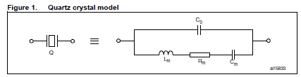
Adafruit Industries - Makers, hackers, artists, designers and engineers!
Learning to design your own PCBs and being able to put together a schematic to solve a specific problem is both a valuable and rewarding skill. There are a number of resources out there to help yo…
willow tartan
sick geyser
By my math you need 16pF total but you've got 2x 16 = 32
So my math was correct regarding 16pf but instead of using 2 8pf I used 2 16pf
willow tartan
I ordered today some capacitors with the value of 8 10 and 13 , to test out. I will come back with more information's after. Maybe I will buy a oscyloscope too :))
latent jungle
FYI. Unless you get an active probe, an oscilloscope's passive probe has about 10 pF of capactiance ...
marsh zinc
I had to look up active vs passive probes. It looks like an active probe has about 10x the impedance of a passive probe at 50mhz. Am I reading this correct? I didn’t see (or understand) the effect on capacitance.
Source: https://www.digikey.com/en/articles/understanding-selecting-using-active-oscilloscope-probes

 worldly schooner
marsh zinc
I had to look up active vs passive probes. It looks like an active probe has abo...
worldly schooner
marsh zinc
I had to look up active vs passive probes. It looks like an active probe has abo...
Yes, that is correct. The benefit of an active probe is its ability to read the higher frequencies without being (as) affected by the parasitic capacitance of the probe.
If you have ever seen the effect an RC circuit has on a fast square wave, the filter has a tendency to round the corners of a rising or falling edge. At really high frequencies, there isn’t any avoiding this with a passive probe.
marsh zinc
@worldly schooner - thanks. I have seen (and demonstrated) the effect of an RC circuit (and just a cap) on the rise/fall edge.
I demonstrated it when showing hardware debounce of momentary contact switch.
I have also had to deal with it when converting raw phototransistor input to digital data.
ionic wigeon
Hey, does anyone know how to make through-holes in EasyEDA with a copper pad on just one side of the PCB?
Or, if that's not possible, how can I manually remove the annular rings from a THT component on one side of a 2-layer PCB?
ionic wigeon
 latent jungle
marsh zinc
I had to look up active vs passive probes. It looks like an active probe has abo...
latent jungle
marsh zinc
I had to look up active vs passive probes. It looks like an active probe has abo...
I didn’t see (or understand) the effect on capacitance.
First, I know it is pedantic, but that graph does not go down to 50 mHz. I think you meant 50 MHz, which is a very different frequency.
Next, don't forget that impedance across frequency shows the reactance which is a combination of capacitance, inductance, and resistance.
For reference, a typical active probe has less than 1 pF, sometimes much less, of capactive loading at DC (or 50 mHz...) while a 10:1 passive probe will have 10 pF.
When measuring the crystal of a MCU, the side actively driven by the MCU can handle the loading of a passive probe. (As in, the oscillator will still run, but what you see on the scope isn't valid.) The other side, however, will essentially see an extra capacitor and prevent the oscillator from running.
marsh zinc
@latent jungle - thanks for injecting better details. (given the 'H' was not capitalized either, I suspect there was no ambiguity for all but the most specialized RF engineers)
Was the linked DigiKey article accurate?
latent jungle
marsh zinc
<@312943079160283137> - thanks for injecting better details. _(given the 'H' was...
Oh, I missed the link. Yes. Anything about oscilloscopes written by Art Pini is accurate. 🙂
marsh zinc
I do my best to include links to source material since a super brief comment will never be sufficient (and quick typing can easily introduce confusing)
unreal bay
ionic wigeon
Hey, does anyone know how to make through-holes in EasyEDA with a copper pad on ...
Not EasyEDA specific. Can you crate a stand alone hole, then add a pad to just one side? How about a thorugh hole that has zero sized pad, then add a pad (as a second part) on just one side? Needing to avoid any design rules checks that might say the copper is too close to a cut edge.
marsh zinc
~~ µMerlin~~ @ionic wigeon - Within KiCAD it is possible to create a through hole with different specs for the front and back layers. I have not tried to create an example matching your details.
Can you can you created/edit a picture of what the pad/hole would look like on a PCB?
Some questions to answer in your description:
- is the hole plated or non-conductive?
- does the pad have thermal relief or not?
- while it likely doesn't make a different to the implementation, what is the size of the hole (this will help visualize what you are attempting)
- how will this hole be used in your design?
unreal bay
marsh zinc
~~ µMerlin~~ <@333612517525946370> - Within KiCAD it is possible to create a thr...
That was not a question for my own use. It was a response to someone else with what I thought might be a path to solve their problem. From your more specific response, it is.
marsh zinc
Oops. I just fixed to tag the OP 🫣
ionic wigeon
unreal bay
Not EasyEDA specific. Can you crate a stand alone hole, then add a pad to just o...
Thanks for the response! While i could do that, would the innerpart of the hole be plated then aswell tho?
ionic wigeon
marsh zinc
~~ µMerlin~~ <@333612517525946370> - Within KiCAD it is possible to create a thr...
"Can you can you created/edit a picture of what the pad/hole would look like on a PCB?"
here a reallife example what i wanna do
 sacred badger
ionic wigeon
"Can you can you created/edit a picture of what the pad/hole would look like on ...
sacred badger
ionic wigeon
"Can you can you created/edit a picture of what the pad/hole would look like on ...
What yer gonna do is place a hole, then a pad on top, and adjust diameters accordingly -- then switch to edit the other layer, and make the initial layer non-visible, and place a pad on that side as well, adjusting it's diameter accordingly

 ionic wigeon
lol you beat me last second, just wanted to post i found the solution :D
make the annular ring on both sides only 0,2mm and then create another flat pad on the backside with the radius 1,5mm. (use the same net aswell, obviously)
with this hack, the topside annular ring is 1,2mm and the backsides annular ring is 0,5mm :)


 ionic wigeon
but still thank you very much for thaking the time to try help me :)
sacred badger
you're very welcome -- hope your PCB arrives with no issues!
ionic wigeon
thanks :)
sacred badger
prob better to use a via instead of a hole, guaranteeing there's continuity between layers -- and as you've learned, place a pad on top and simply adjust it's diameter
ionic wigeon
well i did use a multi layer pad with the small annular ring as the hole
and then simple a bigger surface pad on the buttonside
sacred badger
ah -- in those images above, it looks like it's a via, but tis just a hole -- and im unaware if jlc would make it a via, or if part of the process would make it a via regardless given there's copper on both sides
marsh zinc
@ionic wigeon - I’m still going to see if I can create this with just parameters. If not, then a custom pad is the way to go. (rather than have two pads with the same name, you create a custom “pad”; then it’s one thing if you end up duplicating it) I use custom shaped pads all the time. They are super handy for things like touch pads.
marsh zinc
@ionic wigeon - I tested with the 1x3 through hole header connector. I was not able to achieve your desired result with just parameter changes.
I was able to create your result with the following steps:
- change the tru-hole "pad" to have a 1mm hole and a 1.05mm diameter. (you could have more anular ring if you prefer)
- create an SMD pad on the front coper with a 2mm diameter (again, you can choose to fit your needs)
- Position the SMD pad over the thru-hole pad
- with the SMD pad selected, use "pad edit mode" (CTRL-E on Windows CMD-E on Mac)
- selected the thru-hole pad
- exit "pad edit mode"
Now, there is one "pad" and it is a thru-hole with a large coper area on the front and almost zero copper on the back
ionic wigeon
👀
marsh zinc
The resulting pad is a single entity and may be moved, copied, etc.
BTW: "pad edit mode" is also how to make oddly shaped pads for things like touch sensors. (useful when integrated touch pads into artistic PCBs)
ionic wigeon
uhhhh nice! what rending software ist this? this doesnt look like the easyeda 3d render
marsh zinc
I use KiCAD for my electronics work.
 distant raven
latent jungle
When measuring the crystal of a MCU, the side actively driven by the MCU can han...
distant raven
latent jungle
When measuring the crystal of a MCU, the side actively driven by the MCU can han...
There is a little bit of nuance here that can be important. Higher frequency crystals are going to be more affected by this than lower frequency. Generally I've seen that crystals 16MHz and below typically handle passive probes with only small variances in operation. I've not tried anything between 16-32MHz, though I've found that 32MHz exhibits issues in startup if I'm trying to probe operation. Just some real world nuance. This is also using those cheap probes that come with handheld oscilloscopes so your overall mileage will absolute vary.
woven bluff
@supple pollen I got a NCH8200HV, it's advertised 3-15V input and 170V regulated output but when I input 12V, it drops to 150V.
woven bluff
My next divergence meter, how you think the big 5V tank?
 woven bluff
 pale grove
Maybe a dumb question - I am trying to open/convert some of the adafruit eagle files into KiCAD.
I was following some guides with mapping layers etc.
I see the board being imported - but when I try to link the schematic and board it does not seem to work. Is there something extra I need to do? Or a better way to import them?
flat vigil
pale grove
Maybe a dumb question - I am trying to open/convert some of the adafruit eagle f...
I usually do the auto-layer matching. silkscreen doesn't always work but everything else seems to
unique patio
https://hakkousa.com/ is having a 20% off various things sale this month, including the new FX-888DX soldering station.
pale grove
flat vigil
I usually do the auto-layer matching. silkscreen doesn't always work but everyth...
Tried that but quite a lot missing it seems
 flat vigil
what file are you trying to load?
pale grove
But maybe I am doing something wrong on import? Not sure
Import => eagle
Then I select the auto layer matching
- manually add the milling and images.
Then hit ok
 flat vigil
and what window did you screen grab?


 pale grove
I just tried a fresh one again

Ok now 21

Those errors/warnings are important or can be mostly ignored?
Or how/where would I start fixing them?
For example
Warning: Via connected to unknown net (USB_D+).

It looks correct but maybe I am missing something?
ionic wigeon
Hi everyone,
I’m currently working on a project requiring 4 devices with the same address on a single I2C bus. Since the devices don’t have any address select pins and I have to use these, my only other option is to switch/multiplex the I2C bus itself.
That’s why I searched for suitable ICs and found purpose-built ICs like the PCA9546, which is solely designed for I2C bus switching. However, I do not like the fact that I have to send an I2C command to switch the output channel on the switch itself. So, I googled and found out, that there are also I2C multiplexers, but that got me even more confused since they also control the output channel via a command on the same I2C bus.
This led me to tinker with other ideas, and I found what on paper should be the best solution, but I fear I’m missing something. In theory, a dual 4-channel analog multiplexer with typical <45 ohm impedance and <2 pF output capacitance seems like an easy fit. The datasheet of the random analog multiplexer I chose (SN74LV4052ADR) even has this usage as an application example! But now it begs the question: what about performance?
The purpose-built ICs all list a max frequency of 400 kHz, but my gut feeling tells me that with the parameters of the analog multiplexer, it should easily reach the full 1 MHz my STM32 can output. But if so, why do these purpose-built ICs even exist? Why doesn’t everybody just use the readily available general-purpose ICs?! Or am I missing something? Might there be a problem of crosstalk, its “high” impedance, etc.?
pale grove
It seems the imported footprints have some errors within them

But how would I fix them or set them to be ignored?
worldly schooner
ionic wigeon
Hi everyone,
I’m currently working on a project requiring 4 devices with the sam...
I can’t claim to have a complete understanding of this, but from my experience the main reason is merely a matter of preference. In the application I used a multiplexer, I was monitoring 6 separate temperature sensors, and didn’t need to poll them more than once a second. That plus the lack of spare pins on my peripheral controller made a specialized ic more appealing than an analog mux.
unique patio
ionic wigeon
Hi everyone,
I’m currently working on a project requiring 4 devices with the sam...
Have you looked a these guides https://learn.adafruit.com/search?q=i2c%2520multiplexer, including the overview https://learn.adafruit.com/working-with-multiple-i2c-devices ? The code needed to do the switching is straightforward, and there are libraries to help. This is the standard way to do it.
worldly schooner
More often than not it comes down to control scheme and available pins…
Most I2C devices are small sensors that don’t require high poll rates or take up a huge bandwidth, but the ones that do usually don’t like sharing a bus in the first place.
unique patio
The advantage of the I2C-controlled I2C multiplexers is that you don't need extra pins. And if you have extra pins available to control a non-I2C mux, then maybe you could use those pins for I2C as well.
ionic wigeon
unique patio
The advantage of the I2C-controlled I2C multiplexers is that you don't need extr...
im not keen on bitbanging four I2C-Busses with each controlling a oled display - meaning a pretty high bandwidth
unique patio
ionic wigeon
im not keen on bitbanging four I2C-Busses with each controlling a oled display -...
which controller iC is used for the displays, and what's the microcontroller you are using?
ionic wigeon
oh i didnt even mention this 
STM32F070 and i think the generic ssd1306 but let me recheck nop, the drive ic is called "ch1115"

LCSC Electronics
X050-8848TSWYG02-H14 Newvisio $0.9079 - OLED Display ROHS datasheet, price, inventory C18723010
unique patio
CH1115 according to the datasheet has an "SA0" pin which can change the I2C address by one bit. So you could put two displays on one I2C bus and two on another
ionic wigeon
well the driver inside the oled itself sure
but the oled itself doesnt have it in its pinconnector
unique patio
actually I'm looking at the ch1115 datasheet
ionic wigeon
what what? :o
unique patio
I can't find a ch1114
nevermind my typo. It's ch1115
i just typed it wrong above and then read it back. Anyway, maybe they exposed that jumper on this display?
ionic wigeon
well im not gonna be able to solder a jumper on the flexcable myself^^
for that i would need to scrape the upper surface of while not damaging anything :D
unique patio
it's not exposed on the flex cable, maybe on the board.. I'm looking
ionic wigeon
btw while your at it: why does the datasheet claim the VDD2 (for the DC/DC Conv.) must be atleast 3,5V when that thing is inside the driveric, and its datasheet says it works at 2,8 already. that confused the heck out of me :D
unique patio
I don't know

are you wedded to this display?
The STM32 has two I2C controllers, so if you were able to find a display board that allowed at least one other I2C address, you'd be home free without any external I2C control logic
is this for a commercial design or homebrew?
ionic wigeon
ionic wigeon
btw while your at it: why does the datasheet claim the VDD2 (for the DC/DC Conv....

 ionic wigeon
unique patio
The STM32 has two I2C controllers, so if you were able to find a display board t...
ionic wigeon
unique patio
The STM32 has two I2C controllers, so if you were able to find a display board t...
ha, no.

unique patio
what are your display requirements
ionic wigeon
i kept a secret, i wanna do this 2 times 
in total im gonna use 8 of these mini displays
usecase btw:
 unique patio
ok, then just use a multiplexer IC. Are you writing this in STM SDK or arduino
ionic wigeon
stm32 IDE and SDK* for sure, im already familiar with it through my work
but since thats my personnel project, cant use company tools
unique patio
really, writing the control stuff is not that hard. The analog mux is just a complication
ionic wigeon
unique patio
really, writing the control stuff is not that hard. The analog mux is just a com...
well to be fair, both solutions seems pretty doable / not hard. the question is for me, could the analog multiplexer perhaps even be faster?!...
i mean the datasheet of the analog multiplexer does even has this application as an example listed:
 unique patio
well, that seems fine, if you have the pins. The advantage of the i2C-controlled multiplexers is that it doesn't require any extra pins
ionic wigeon
the switch IC does guarantee a functioning speed of 400khz, but the analog mux could perhaps be even faster
unique patio
so if you are already short on pins, it's a no-extra pins solution
ionic wigeon
unique patio
well, that seems fine, if you have the pins. The advantage of the i2C-controlled...
since the cheapest stm32 on lcsc with usb is a 64pinner anyway, not a problem at all
unique patio
can you run the displays at 1 MHz?
ionic wigeon
unique patio
I would say just try it. if you need to add a little settling time, that's easy
ionic wigeon
fair question, i never checked omg.
and: no 
well that solves the question :D
then there really isnt an advanced to using a multiplexer. i throught all of the
X050-... oled displays feature 1mhz as everyone i checked previously did
but OFCOURCE the one i decide to use doesnt arrggghh
but thank you very much @unique patio
unique patio
you're welcome 🙂
pale grove
Another question - I want to integrate a 18650 battery. The usual battery holder is too big for my enclosure.
I found these boards here - so maybe I can replicate this type of connection? Are there any references on how to make these in KiCad?

Or is it a simple hole with some copper around it?
latent jungle
pale grove
Another question - I want to integrate a 18650 battery. The usual battery holder...
Those are plated slots. One approach would be to make an oval pad with an oval hole.

You'd have to watch the slot requirements of the PCB fab you're using. Otherwise, you could created "holes" and communicate to the fab you want them plated manually.
A custom footprint (so you can add the vias) is probably a better approach. And would probably require communication with the fab to know it needs to be plated.
sacred badger
@ionic wigeon that looks p dope tbh
supple pollen
woven bluff
<@348911944486486016> I got a NCH8200HV, it's advertised 3-15V input and 170V re...
What load? Is it adjustable?
ionic wigeon
sacred badger
<@333612517525946370> that looks p dope tbh
english isnt my first language and google is telling me your either talking about meth or transistor n- and p-doping ahaha but thanks anyway i guess^^
supple pollen
I believe it is an abbreviation of an idiomatic phrase. So the long form would be "that looks pretty dope", where "pretty dope" is slang for good, nice, or well done.
ionic wigeon
ahhh i see, in that case thanks :D
 elder peak
I mean, that was confusing for me because I was nerd child and so transistor doping was ... um, the first meaning I knew.
sacred badger
thanks madbodger
 clever shadow
Do you think a 1k resistor is a good value between a MCU logic pin and MOSFET gate? This would be to protect the MCU in the event the MOSFET fails, since they otherwise don't really sink current during normal operation.
supple pollen
Depends on the voltages on the drain and source, but in most cases that would be sufficient
shy spear
is this a good 3.3v clean PSU (its going in a car)
 uneven cloak
shy spear
is this a good 3.3v clean PSU (its going in a car)
uneven cloak
shy spear
is this a good 3.3v clean PSU (its going in a car)
Have you allowed for the vehicle voltage variations as most vehicles can vary between 10.5 and 13.8 volts. The low side on some can go to 9 and high side can go up to 15 volts.
shy spear
uneven cloak
Have you allowed for the vehicle voltage variations as most vehicles can vary be...
Yes I have
shy spear
A slight revision to fix some errors that I caught

 spring hornet
Good morning! 🙂
Can you recommend me a wire like leak sensor that I can wire into an esp32?
That can be a digital sensor right? So no additonal component requred, same as like door sensor.
hushed ermine
spring hornet
Good morning! 🙂
Can you recommend me a wire like leak sensor that I can wire i...
Does this meet your needs? https://www.adafruit.com/product/4965
Keep wet things wet and dry things dry by detecting when the dry things get wet by accident! This palm-sized cherry-red water sensor is simple and easy to implement in your ...
 stark arch
Anyone ever use custom servo horns for their project? Looking for a way to possibly screw something into a horn, but options look limited. Was possibly looking at the following combo, not completely sure if they are compatible:

Add even more power to your robot with this metal-geared servo. The tiny little servo can rotate approximately 180 degrees (~90 in each direction), and works just like the standard kinds ...
The Losi Aluminum Servo Horn, 20T: GROM from our collection of the best RC car and truck Parts, is hobby-grade quality at a great value. Find the RC car parts and accessories you need at www.towerhobbies.com!
 lyric nymph
Does anyone know which connector is in use on this Adafruit EyeSpi breakout?
https://www.adafruit.com/product/5613
I plan to pull the connector off that board and use it on my own board, but I need to make sure I get the footprint correct!
worldly schooner
lyric nymph
Does anyone know which connector is in use on this Adafruit EyeSpi breakout?
htt...
I could offer a guess, but honestly all of the 0.5mm FPC connectors of the same pin count basically have the same footprint. The only slight difference is usually the size and position of the support ground pads, but oversizing them like on https://www.adafruit.com/product/1492 can easily compensate for any margin of error.

Connect to those pesky 0.5mm pitch connectors that you may run across with an FPC stick. We designed this for use in house, to quickly connect to 50pin 0.5mm pitch flex cables we need to ...
ripe dawn
I'm guessing the answer is "it depends" and "would recommend against", but…
Does anyone know if it's safe to connect 120VAC to perfboard? To clarify, my intent is to immediately pass this into a low current (~2mA) voltage divider to detect the signal, but I want to make sure nothing is going to arc on its own before it gets to the resistors.
I'm planning to run the wires into a terminal block with 0.2in pitch, but want to make sure there's no chance of it "double jumping" through the plating around the holes.

 knotty tiger
if you have to ask, the answer is no
 dark grail
ripe dawn
I'm guessing the answer is "it depends" and "would recommend against", but…
Doe...
dark grail
ripe dawn
I'm guessing the answer is "it depends" and "would recommend against", but…
Doe...
i would just plug a cellphone charger into a normal 120 outlet, and then detect if its producing 5v on its usb port
then your only dealing with 5v and its far safer
ripe dawn
In this case it's not an outlet though. It's inside an appliance, and one of the two signals I'm trying to register is a buzzer which only rings for about a second. It seems like a lot of wall chargers take at least some time before they're outputting 5V so not sure if it would be enough in this case.
dark grail
ah, that complicates it some
worldly schooner
The board itself is fine, but the air gaps between solder blobs may not be. I would keep any ac power away from perfboard.
I also would use a transformer instead of a resistive divider to provide some isolation from mains. Just to be safe.
dark grail
ah yeah, that would definitely help a lot
 copper lintel
Does anyone know why my GND symbols get tied to one of my 3.3v nets after I update the board from the schematic? Is it a netclass issue?
Really annoying that all of my GND nets are actually 3.3v for some reason.
this is really weird
 copper lintel
Nevermind, it was an issue in my custom symbol!
No idea what the issue was, but changing a hidden pin from "power input" (its an unused pin supposed to be tied high) to "passive" seemed to fix it
If someone knows why this happens I would love to know
unreal bay
worldly schooner
I also would use a transformer instead of a resistive divider to provide some is...
Transformers are bulky. How about a full wave bridge and optoisolator. Not mounted on the perfboard. Output from the optoisolator the only wires to the perfboard. Examples seen when searching for zero-crossing detectors.
uneven cloak
unreal bay
Transformers are bulky. How about a full wave bridge and optoisolator. Not mount...
Once again if you have to ask DON'T do it. I do believe questions or answering anything about High voltage is against server rules
ripe dawn
- there is no mention about anything involving voltage in #welcome, #code-of-conduct or #announcements
- what is the cutoff for "high voltage"?
uneven cloak
ripe dawn
1. there is no mention about anything involving voltage in <#330410763594498050>...
- If there isn't there should be . 2. Anything where your obvious lack of knowledge and care about physical harm can involve you or others. Generally considered to be anything over 32volts.
uneven cloak
ripe dawn
1. there is no mention about anything involving voltage in <#330410763594498050>...
How about this * Discussion or promotion of activities or projects that intend or pose a risk of significant harm.
unique patio
ripe dawn
1. there is no mention about anything involving voltage in <#330410763594498050>...
In this case, it's due to experience and knowledge folks have about working with mains voltage. Mains voltage can easily be fatal. Considerable lengths are taken to make mains voltage terminals inaccessible to you inside electronic equipment, light switches, plugs, bulb sockets, etc. Putting bare mains voltage on a perf board is an example of not taking care to make it very inaccessible
knotty tiger
unique patio
In this case, it's due to experience and knowledge folks have about working with...
@ripe dawn also there are safety standards for PCBs that carry mains voltage, and a typical perfboard almost certainly doesn’t satisfy them. i’d suggest having a qualified professional do that work
tulip swift
So not suggesting anyone add mains voltage to a perf board if they don't have the knowledge or experience, but did want to note, there is no reason, if you did do this, that the two lines HAVE to go in adjacent holes as everyone seems to be suggesting. Spread them out. Sheesh! 
worldly schooner
I mean there are a number of ways to make it safer. Spreading them out, encapsulating with a nonconductive epoxy, adding fuses, etc. Generally, however, it’s not recommended to play with mains voltages in DIY projects due to high potential current and risk of real bodily harm if proper precautions aren’t taken.
I do some electrical work on my own house on occasion, so I won’t say you absolutely cannot do it, but I’m not qualified enough to make recommendations on how to do such work, let alone teach anyone how to stay safe while doing so.
I did suggest a transformer as an off the shelf option to step the voltage down, but I probably should exercise more caution when offering advice regarding mains…
tulip swift
ripe dawn
In this case it's not an outlet though. It's inside an appliance, and one of the...
So back to the original problem to be solved, is the buzzer on the appliance run off 120/240V (older or simplier appliances) or is it driven off a lower voltage (newer designs often utilizing MCUs boards to run everything)?
ripe dawn
directly off 120V, unfortunately
tulip swift
Is it wires? Or soldered to a board? If the former, wires going to the buzzer, then easiest solution would be a non contact current sensor. Basically a clamp around the wire that gives you a voltage proportional to the current running through it. For example https://www.electromaker.io/shop/product/non-invasive-ac-current-sensor-5a-max

Seeed Studio Accessories Non-invasive AC Current Sensor (5A max)
ripe dawn
Ah yeah I had looked at these and probably need to give them another look. I think there's at least one spot where I could sneak these around a wire instead of tapping into the board. What's the right way to read values from these? I'm seeing a lot of them being sold bundled with an ADS1115, but could I just use the built in ADC on various MCUs if I don't care about a precise current reading, just whether or not there's current?
worldly schooner
With a 0-1V output, you're going to need a fairly precise ADC to discern a milliamp current. A typical piezo buzzer draws less than 20mA IIRC, and this current sensor looks like it'll translate current at 0.2V/A. 20mA current is 0.004V, so you may want to consider an amplifier circuit or a different current sensor.
inland jungle
also determine whether you can see that above the noise
uneven cloak
Depending on the country there are legal requirements on distance of mains cable to data cables and a lot of requirements for isolation and intrusion in most countries. I haven't seen "spreading them out" in any countries legislation. @worldly schooner @tulip swift
worldly schooner
This is true under many standards, yes. Please do not sell or distribute anything that could be in violation of these codes.
(With perfboard, I’ve only ever built engineering prototype and proof-of-concepts, neither of which are saleable or intended for a permanent installation.)
copper lintel
https://www.digikey.com/en/products/detail/stmicroelectronics/LD57100J330R/21348950
Am I crazy, or is this not possible? I would like to use this part in my design, but have a few questions.
How can it supply 1A, when the balls are just 0.254mm? Can that wide of a trace really do 1A?
Is the dropout voltage really just 40mV, or is there some other catch, like with the Vbias pin?
If I use a LiPoly battery from adafruit, can I just tie the Vbias to the input?
Can I use standard solderpaste for it, or do I need to use balls for it?
supple pollen
I think you can use paste. I see two possible gotchas with it: one is it needs a separate bias supply, unlike an ordinary 3-terminal regulator. The other is the 60°C/W thermal resistance, if you're drawing an amp, you'll need to keep the supply voltage near the output voltage to avoid excessive dissipation.
copper lintel
Got it, thanks! I only plan to draw about 700mA for short periods of time, but the bias is a deal breaker, as I dont have any other source of power for that
ionic wigeon
Does a more accurate clock help the ADC on an STM32(G030) in a noticeable way? I'm thinking of adding an external crystal, but since the 32-pin version doesn’t support HSE crystals, I'd need a full crystal oscillator, which is about 10x the cost. By “noticeable” I mean an actual improvement in accuracy or SNR. I could see more stable timing helping with sampling consistency, but maybe the internal RC oscillator is already good enough for this. Anyone have experience with this?
And yes, i know, a clean supplyrail and the layout itself is probably way more important then the clock, but thats whats interests me... by how much really :o
supple pollen
I don't have experience, but my understanding is that the clock has little effect on ADC accuracy. For another project I'm working on that requires clock accuracy (for different reasons), I found that I could get a little packaged 1.5ppm accuracy oscillator for around $7.
dark grail
supple pollen
I don't have experience, but my understanding is that the clock has little effec...
what if the clock frequency is too high? i assume there must be some minimum period time
ionic wigeon
dark grail
what if the clock frequency is too high? i assume there must be some minimum per...
what do you mean with that? i could always clock/divide it down but the question was if a more stable external clock would improve the ADC itself or if thats unnecessary
dark grail
i was thinking more along the lines of overclocking the adc
ionic wigeon
oh no thats not what i had in mind^^
supple pollen
dark grail
what if the clock frequency is too high? i assume there must be some minimum per...
I'm making the assumption that the clock used is an appropriate frequency. I figured the question was whether clock accuracy (as opposed to frequency) affected ADC accuracy.
Overclocking the ADC presumably would affect accuracy
ionic wigeon
supple pollen
I'm making the assumption that the clock used is an appropriate frequency. I fi...
yes it would. 16mhz to be precise.
 gloomy lion
Making an RP2354 thing for the first time and wanted to double check if my schematic and circuitry look okay - I know the PCB view is a little messy and hard to follow tho


I'm very used to designing for the RP2040 and I just want to be sure that I'm not making any obvious newbie mistakes with the component layout
sacred badger
quick question -- trying to wrap my head around how this LED tree from lowes works. it appears there's a central hub at the top that distributes power (5v/G), but all data lines are connected... yet, there's animations that have a spiral effect -- can't be something like ws2812b or whatever, bc if all data lines originate at same place, spiral effect would be impossible(?!) i'd think
it's powered by a STC8H1K08, and has an 8MB 25* flash chip which i dumped with a CH341, and viewing with a hex editor, one can somewhat see the animations

im somewhat assuming it's treated as a panel, of sorts -- 18px wide. was never a software person
latent jungle
ionic wigeon
Does a more accurate clock help the ADC on an STM32(G030) in a noticeable way? I...
Voltage (vertical) noise will almost always be higher than time/sampling error.
granted, at 16 millihertz, things can be different. but you probably meant 16 MHz, which is a couple of orders of magnitude faster.
(just worth mentioning because it’s a weird units error to make when the primary concern is timing)
ionic wigeon
latent jungle
Voltage (vertical) noise will almost always be higher than time/sampling error.
i though so too^^ but will see how clean i get my voltagerail in the end. And yes, ofcourse i meant 16MHz :D
just wrote that on my phone without much care since in the context only MHz would make sense anyways :D
supple pollen
sacred badger
quick question -- trying to wrap my head around how this LED tree from lowes wor...
Could be each string is (virtually) offset by one position. GE made some addressable lights a while back, this could be related.
sacred badger
supple pollen
Could be each string is (virtually) offset by one position. GE made some addres...
thx for that -- done got me lookin at SK9822 strips lmao
knotty tiger
i think Adafruit even sells "fixed address" LED strings that have similar properties
 golden wasp
Hi, I have bought an Adafruit 128x32 OLED feather wing for an Arduino UNO R4 Minima project. The display is 3.3V and the UNO is 5V so I've bought an Adafruit 4 Bi-Directional Level Shifter (https://www.adafruit.com/product/757). I tried to run the matching ssd1306_128x32_i2c example but the display doesn't do a thing. I've tr ied the display with an Adafruit ESP32 V2 and with that it works. However I need to make this work with the UNO. I've connected the 5V and the ground to the HV side of the level shifter, SDA to B1, SCL to B2, the display to the LV side. This is the way it should work, right? (noob here)


 brave vigil
golden wasp
Hi, I have bought an Adafruit 128x32 OLED feather wing for an Arduino UNO R4 Min...
brave vigil
golden wasp
Hi, I have bought an Adafruit 128x32 OLED feather wing for an Arduino UNO R4 Min...
https://learn.adafruit.com/adafruit-128x64-oled-featherwing/wiring-to-other-microcontrollers says you also need to connect the RST pin of both the MCU dev board and feather wing together. I'm not sure how to do that with the level shifter.

Easily add a gorgeous 128x64 OLED to your Feather project!
worldly schooner
LV needs to be connected to a 3.3v source. The level shifter does not do this power conversion for you.
The uno should have a 3.3v output next to the 5v output.
Use the breadboard to connect 3.3v to both the display and LV.
golden wasp
brave vigil
https://learn.adafruit.com/adafruit-128x64-oled-featherwing/wiring-to-other-micr...
I think that is only if you want the reset button on the oled wing to work (i.e. you made the reset button on the main feather board unreachable by putting the oled wing on it.
golden wasp
worldly schooner
LV needs to be connected to a 3.3v source. The level shifter does not do this po...
Thank you so much 🙏 It works now 🎆
❓ one more question: the display seems to attached to the pcb with a drop of glue. lets say I want to have the display flush with the case. suppose I'm carefull enough not to damage the flex cable, can I pry the display from the board and fold it 180 degrees (thus facing the back of the pcb). It would give me just enough wiggle room to better install the display. or is it a foolish idea?
unique patio
golden wasp
❓ one more question: the display seems to attached to the pcb with a drop of glu...
I think it's double-stick tape, not glue. Do you see glue ooze?
worldly schooner
golden wasp
❓ one more question: the display seems to attached to the pcb with a drop of glu...
It is possible to pry the display off the pcb, but I’d say it’s quite risky. Mechanically, the adhesive holding the display also doubles as strain relief for the flex cable, so undoing that would make your assembly that much more fragile.
The typical method of flush mounting is to use the mounting holes on the pcb.
unique patio
I agree with Hem.
golden wasp
worldly schooner
It is possible to pry the display off the pcb, but I’d say it’s quite risky. Mec...
pale grove
are there any "long" USB-C connectors? I need something that's like 20 mm
Or alternatively I would need to add wires to the USB-C connector instead
brave vigil
pale grove
are there any "long" USB-C connectors? I need something that's like 20 mm
Depending on the connection type (USB host vs device), you could try using a USB Type-A connector with this adapter: https://www.adafruit.com/product/4175

As technology changes and adapts, so does Adafruit, and speaking of adapting, this adapter has a USB A plug and a USB C socket so your older computer or laptop can catch up to the ...
pale grove
Ah no I meant for mounting on a PCB
supple pollen
It may be possible to put a sort of extension on your PCB to hold the connector out a distance, but I don't know if it would work for your particular use case.
brave vigil
pale grove
Ah no I meant for mounting on a PCB
An additional USB Type-A port is what would be mounted on the PCB, when using my suggestion.
latent jungle
pale grove
are there any "long" USB-C connectors? I need something that's like 20 mm
worldly schooner
latent jungle
like this? https://www.mouser.com/ProductDetail/Same-Sky/UP20-C-F-G-FL-1-P12-TR
Long that may be, but it isn’t 20mm long. Datasheet suggests closer to 13mm.
latent jungle
Then I doubt such a thing exists
 gilded grail
Not 100% sure if this is the right channel for this... But!
I picked up a KB2040 for this controller project I'm working on. I'm looking for a solution that would kinda be described as a "zero resistance volume knob." So I found some "free spin" potentiometers and the two I've tried so far, just don't really have that zero resistance to them that I'm looking for.
So I knew that logitec has that "free spin" scroll wheel that they market on some of their mice, bought one of those and took it apart to see the magic in the sauce. To me it looks like a IR sensor on a custom PCB, maybe someone here knows more about these mice than I do and could comment on that.
But I bought (picture A/ black PCB) because I thought it would work the same way the scroll wheel on the mouse did, but I can't really get it to read which direction it's rotating in... which is a no go on the controller idea if I can distinguish whether it's spinning left or right...
Soooo.. I thought about getting (Blue PCB) and trying to stick one of those discs from the other sensor in there and go about programming it the way I need it to work. But would just like some input from some more knowledge people before I get 100$ into this project and none of the parts work for what I'm looking to do...
Thanks in advance for any input and can provide more references for things!

 supple pollen
gilded grail
Not 100% sure if this is the right channel for this... But!
I picked up a KB2040...
supple pollen
gilded grail
Not 100% sure if this is the right channel for this... But!
I picked up a KB2040...
Basically, you use two sensors per wheel to generate what's known as a "quadrature" signal, which can then be decoded to derive both direction and speed. There are encoders available that integrate the wheel and both sensors.
gilded grail
Is there something specific I should be googling here?
Are the encoders your talking about free spinning OR would it be something kind of like the first IR sensor pictured with some custom hardware around it?
Just kind of trying to pick which rabbit hole I'm jumpping into
gilded grail
https://www.amazon.com/dp/B081W2TY6Q?ref=ppx_yo2ov_dt_b_fed_asin_title
These are the actual sensors that I bought already, not too sure if I just wired them wrong, or those just don't read directional data.

Description: Features: 1, the use of imported groove coupler sensor, slot width 5mm. 2, output status indicator lamp output high, output low lights. 3, block, output high; no shelter, output low. 4, the comparator output signal clean, good waveform, driving ability, than 15mA. 5, the working volt...
unreal bay
Quadrature encoding is based on the encoding wheel (multiple variations) and dual sensors, to be able to detect both speed and direction. Whether that is free spinning or not is completely separate. That is controlled by the mechanics of how it is mounted.
Do a search on quadrature encoder to see how the 2 sensors allow direction detection.
pale grove
Another question - which resistor is meant here that needs to be replaced?
The R3 10k?
 pale grove
And for the LED - doesn't it need 5V?

 supple pollen
pale grove
Another question - which resistor is meant here that needs to be replaced?
The ...
supple pollen
pale grove
Another question - which resistor is meant here that needs to be replaced?
The ...
The resistor connected to the PROG pin (which programs the charge current). R9, in this case.
supple pollen
pale grove
And for the LED - doesn't it need 5V?
The LED is designed for 5V, but lots of people run them on 3.7V (from a lithium cell) or even 3.3V successfully. You need enough forward voltage to power the bandgap of a blue LED with a little headroom for current regulation (the WS2812 uses current regulation instead of fixed resistors), and 3.3V is (barely) sufficient.
pale grove
Ah ok - thanks!
So in theory I could just hook it up to a 5V source too without any extra components?
supple pollen
The LED will run well from 5V but a 3.3V signal may not be able to control it reliably.
So you may need a level shifter if your controller is 3.3V
unique patio
pale grove
Ah ok - thanks!
So in theory I could just hook it up to a 5V source too without...
If this is for an external WS2812, sure, you can try this. If this is for a board you are making (e.g. status indicator), play it safe and drive it with 3.3V.
pale grove
unique patio
If this is for an external WS2812, sure, you can try this. If this is for a boar...
It will be for a board but I need 5 LEDs
unique patio
pale grove
It will be for a board but I need 5 LEDs
that is still OK if your 3.3V regulator can supply the current
or you can add a level shifter
gilded grail
unreal bay
Do a search on quadrature encoder to see how the 2 sensors allow direction detec...
I had found a pretty good video explaining it. But all the quadrature encoders I've found on sites make them kind of look like regular old rotary encoders? Is there something I need to be adding to my searches to get closer to what I'm looking for? or are they actually more like rotary encoder and inside the pot it's just the optical disc like I'm looking for?
supple pollen
They're all rotary encoders, but you presumably want one without detents so it rotates smoothly
gilded grail
so you're saying get an "optical quadrature encoder" and not a "magnetic quadrature encoder"?
Or how can I tell if it has any detents inside of the pot without opening it?
gilded grail
This is what I was looking at. But I have the adafruit kb2040 and this encoder has a review that says it doesn't work well with anything under 7V.

Model: incremental rotary encoders, AB two phases, 1. It can be used to measure the rotational speed, Angle and acceleration of the object and the length measurement. 2. Suitable for a variety of intelligent control displacement measurement ,automatic fixed-length automatic guillotine paper machi...
unreal bay
gilded grail
I had found a pretty good video explaining it. But all the quadrature encoders I...
Various sensor technologies can be used for quadrature encoders. Mechanical, magnetic, optional, and anything else that can sense a presence or absence at a scale and resolution to implement that '90°' phase shift needed. With varying resolutions and accuracy. How the shaft that is attached to is mounted determines whether it is 'free turning' or not. If you can find a simple shaft and bearing of the right size, you could mount (for example) an optical encoder wheel on that, then position (either reflective or break beam) sensors to read it. Add a knob of your choice to the shaft, and you are ready to go. For a DIY version like that, the fiddly part is positioning the sensors to get proper 90° phase shift. I have no information about specific products. Just for playing, I have taken apart old optical mice that had a pair of encoder wheels. For detection of X an Y motion.
gilded grail
unreal bay
Various sensor technologies can be used for quadrature encoders. Mechanical, mag...
this is esentially what my plan was, but... I bought those speed sensors and they just don't read direction like I thought they did. I'm curious if I get one in a pot like the one I linked above your message would work for how I'm talking about using it. It would make printing housing and the CAD work a lot simpler for that part of the controller. But madbodger had mentioned detents.
Unfortunately I'm only like a couple hours into this over the last month or two. So I'm okay at wiring up controllers and arcade cabs with some simple boards. I'm still really just learning on the custom side of things. 😓
supple pollen
Detents are a mechanical feature that simply makes it "click" into a number of positions. Without them, it would turn smoothly. You don't have to open it up, you can easily feel if it has detents by turning it. From your original description, it seemed to me like you wanted smooth rotation. There are several very small magnetic and optical encoders available here https://www.pololu.com/category/157/encoders-for-micro-metal-gearmotors intended to be mounted on motor shafts. There are, of course, stand-alone ones as well.
orchid galleon
I was about to ask if 'free spin' meant 'no detent' or if it meant 'very low friction'.
supple pollen
Or just continuous rotation, as opposed to an ordinary potentiometer which can only rotate 270° or so.
pale grove
Another specific question.
I am working on a custom charging cable for a device.
On that charging cable I want to add some kind of LED indiator so that I know if the device is charging or not.
Is there a simple approach to this without using a microcontroller?
Or do I need one?
I basically have V+ and GND available from a USB-connector