#help-with-hw-design
1 messages · Page 31 of 1
 limber thunder
make it cleaner
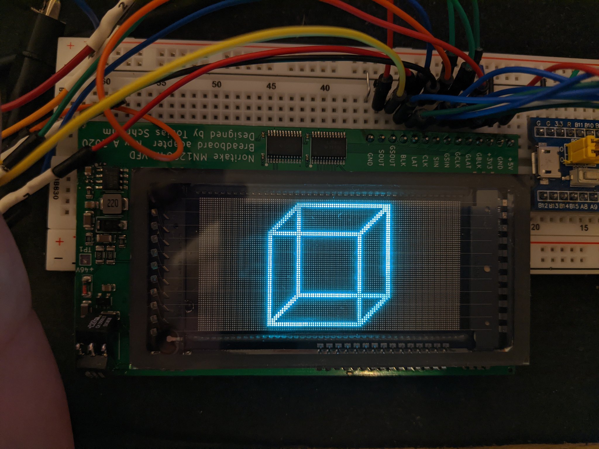
https://kittenlabs.de/mn12864k-vfd/
might yoink some stuff from here
 supple pollen
Oh, that's an excellent find!
limber thunder
so this is confusing me a bit

the board as well as the pins on the datasheet model count 21 but there are extras in the pin list
i think two more
vs

NP could mean no pin
yeah it does
supple pollen
Yeah, the groups of three at the far ends are the filament ends
It's neat that it includes the shift register and drivers
 clear matrix
Hi guys, been googling for a bit and just decided to hear some opinions from you:
Do you know of good SOT23 mosfets which work with 3v3 and can handle around 1A with that gate voltage?
Nevermind, looks like DMN2058U is a pretty good bet.
supple pollen
clear matrix
Hi guys, been googling for a bit and just decided to hear some opinions from you...
I like the A2SHB which is ubiquitous in low-cost devices because it meets those specs and is not expensive
limber thunder
whelp ill return in two weeks to finish wiring the vfd
thanks for all the help madbodger
clear matrix
supple pollen
I like the A2SHB which is ubiquitous in low-cost devices because it meets those ...
Oh Thanks, I'll look it up 😊
 gloomy lion
Anyone have recs for efficient 12V-5V regulators? I'm looking at the
MIC5219-5.0YM5-TR since 500mA is just enough for what I need, but it's a bit pricey because it has some extra features which I wouldn't really need or use. Just needs to power an attiny and around 8 WS2812-like LEDs. It'll also be responsible for charging up a supercapacitor but I'm not sure the maximum output current is enough for a reasonable amount of charge if it's only on for a few seconds at a time

DigiKey Electronics
Order today, ships today. MIC5219-5.0YM5-TR – Linear Voltage Regulator IC Positive Fixed 1 Output 500mA SOT-23-5 from Microchip Technology. Pricing and Availability on millions of electronic components from Digi-Key Electronics.
 distant raven
gloomy lion
Anyone have recs for efficient 12V-5V regulators? I'm looking at [the
MIC52...
distant raven
gloomy lion
Anyone have recs for efficient 12V-5V regulators? I'm looking at [the
MIC52...
LDO will never be efficient dropping from 12V to 5V. That 7V 500mA difference will always be lost as heat. You need a DCDC regulator
gloomy lion
Oh! Very good to know, thank you
Still fairly new to designing for anything outside of 5V-3.3V
distant raven
This should work nicely https://www.digikey.com/en/products/detail/RT6254AHGJ8F/6205455

DigiKey Electronics
Order today, ships today. RT6254AHGJ8F – Buck Switching Regulator IC Positive Adjustable 0.6V 1 Output 4A SOT-23-8 Thin, TSOT-23-8 from Richtek USA Inc.. Pricing and Availability on millions of electronic components from Digi-Key Electronics.
Gives you a lot of headroom
It’s adjustable so you just use the components specified in the data sheet for 5V out and you’ll be good

And page 18 will have a view of what your physical layout on the PCB should look like
gloomy lion
Very nice, thanks! This sounds like it'll do nicely
supple pollen
gloomy lion
Anyone have recs for efficient 12V-5V regulators? I'm looking at [the
MIC52...
You can also get prebuilt three terminal switching regulators that are easy to use and efficient. https://www.digikey.com/en/products/detail/recom-power/R-78E5-0-1-0/4930585

DigiKey Electronics
Order today, ships today. R-78E5.0-1.0 – Linear Regulator Replacement DC DC Converter 1 Output 5V 1A 8V - 28V Input from Recom Power. Pricing and Availability on millions of electronic components from Digi-Key Electronics.
gloomy lion
Might be a bit bulky for what I'm working on now but looks useful for future stuff! I'll definitely keep it in mind
distant raven
supple pollen
You can also get prebuilt three terminal switching regulators that are easy to u...
I would absolutely use these if I had a project big enough
supple pollen
I do use them, they're handy (black block on left near the AVR chip)

 worldly schooner
I’ve used those regulators at my previous job. Not an application where I should’ve needed one, but it certainly worked without any headache haha
gloomy lion
distant raven
Just to be sure, does this look right for a 5V output?

sorry if it's a little messy, just making sure I have the values right before I tidy it up visually
I'm assuming Cout is a combination of C2/C3 in the example (C4/C5 in mine)
also doubtful about whether AGND is hooked up right. I assume connecting it to GND isn't quite right but I'm also not really sure where else I'd connect it haha
distant raven
gloomy lion
also doubtful about whether AGND is hooked up right. I assume connecting it to G...
Seems right. If you’re worried about AGND you can usually put a small value ceramic capacitor like a 0.1uF between it and GND to isolate it a little more
It’s a decent practice to use in potentially noisy environments like around switching regulators
Though I suspect in most hobbyists situations it won’t make too much a difference to hook it right to ground
gloomy lion
Another little cap is only a few cents so I might as well do it right
Thanks again, I appreciate the advice 
distant raven

 cursive sentinel
I'd lean towards a ferrite rather than a cap.
gloomy lion
oh cool that makes things easy
distant raven
They suggest just a via connection. So just call it ground and then in layout follow their suggestion to drop it to via to a solid ground plane below
distant raven
cursive sentinel
I'd lean towards a ferrite rather than a cap.
Being a 2MHz switching regulator that might introduce a little more noise would it not?
cursive sentinel
Depends on component selection.
distant raven
Fair
gloomy lion
Just out of curiosity, is there any noticeable delay in how quickly the regulator kicks in?
would it be fair to call it "instant" for all intents and purposes
 tough matrix
distant raven
tough matrix
distant raven
why connecting by via imporves noise imunity (compared to direct connection on same layer)?
distant raven
tough matrix
why connecting by via imporves noise imunity (compared to direct connection on s...
More impedance plus it’s a narrower return path
Vs just radiating any switching noise into the same plane
gloomy lion
gloomy lion
would it be fair to call it "instant" for all intents and purposes
glancing at the datasheet tells me that yeah, it looks pretty quick lol, I don't think I really have to worry about delay
distant raven
Yeah, few msec
gloomy lion
beautiful
gloomy lion
is it wrong for me to assume that I can have the supercapacitor on the 5V rail like this, between the regulator output and the ATTiny? I feel like it should be more complicated than that

maybe a resistor somewhere to limit the current the cap draws so that it doesn't overload the regulator? Or do I not need to worry about that?
distant raven
Should be okay
gloomy lion
Sick
distant raven
gloomy lion
Sick
Only thing I might do is gate the super capacitor output based on 12V in being present or not
Using a P-Chan mosfet, just need Vgs to be like as high as -9V
gloomy lion
I was thinking I could just toss a diode in there so that the supercapacitor never touches the LEDs and is only powered by the 5V reg directly - would a mosfet be a bit more efficient there?
the microcontroller is the only thing that needs to stay powered when 12V isn't present
distant raven
True
gloomy lion
or do you mean gate it so that the cap is bypassed entirely when 12V is on, and the attiny is powered by the 5v reg, so that the cap can charge up a bit more
distant raven
Yeah, you’d still need a diode for 5V to reach the cap when 12V is on though so
So you could probably just get away with a diode
gloomy lion
Awesome 👌 I'll do some digging on both options
Thanks a ton for your help, really appreciate it
tough matrix
I am designing a carrier board, onto which I want to solder Adafruti QT Py board.
I want to solder it flat, using the castellated pads of QT Py.
Anyone knows if there is a ready footprint for that in KiCad?
I didn't find one.
(Sure, it woudl probably take me 1/2 hour to make my own, but I am lazy)
supple pollen
There are Eagle files, which I think KiCAD can read https://github.com/adafruit/Adafruit-QT-Py-ESP32-S3-PCB

GitHub
PCB files for the Adafruit QT Py ESP32-S3. Contribute to adafruit/Adafruit-QT-Py-ESP32-S3-PCB development by creating an account on GitHub.
tough matrix
supple pollen
There are Eagle files, which I think KiCAD can read https://github.com/adafruit/...
that's not quite what I am looking for.
These are the files for Qt Py board itself.
I need footprint for the carrier board, with pads to which the QT Py will be soldered.
distant raven
tough matrix
that's not quite what I am looking for.
These are the files for Qt Py board itse...
I think I shared an eagle one previously. You should be able to put it in a quick eagle project, import the eagle project to KiCAD and extract the footprint
Link to the eagle library
Or add it here: https://www.snapeda.com/parts/add/
Upload symbols, footprints, 3D models and simulation models to SnapMagic Search in Eagle, Altium, KiCad, OrCad/Allegro, PADS, Pulsonix formats.
There ya go @tough matrix
tough matrix
Thanks a lot!
 sweet cairn
I noticed that the Adafruit Macropad has been updated to use the PAM8302A chip in place of the PAM8301 which has been discontinued.
However the schematic and PCB design files haven't been updated to reflect the change.
Would it be possible to publish the updated design documents? Whom can I contact regarding this?
I've been struggling to implement the PAM8302A chip in my own project for a while now, so it'd be really helpful to me
 unique patio
sweet cairn
I noticed that the Adafruit Macropad has been updated to use the PAM8302A chip i...
unique patio
sweet cairn
I noticed that the Adafruit Macropad has been updated to use the PAM8302A chip i...
Here is the schematic. Unfortunately the part values aren't showing when I imported it into kicad! I had a free version of Eagle but it's no longer running on my box.

I opened this issue: https://github.com/adafruit/Adafruit-MacroPad-RP2040-PCB/issues/2
sweet cairn
unique patio
Here is the schematic. Unfortunately the part values aren't showing when I impor...
Thank you so much!
It's way beyond the time people go to sleep in the part of the world I live in 😅 what I mean to say is I shut down my laptop a while back and am about to head to sleep, but I'm going to cross check with my schematic first thing in the morning.
Would it be possible to know the values of the caps and resistors as well? Wondering whether I chose the wrong values there.
Also something I just noticed is that you're not using ferrite beads + caps in between the buzzer and the amp IC. The datasheet had recommended them and so I put them in my design, was that a mistake? Could it be possible that's causing it to not work?
Also also something I just noticed - you're not using a trimpot either. Ig you chose a resistor of 20k value to have it on maximum volume the entire time?
I used a trimpot in my design.
Hmmmm, now I'm wondering if I overcomplicated my design too much.
Geee I'm too excited lol, I just want to get this thing working and get it over with, I've put in too much time and effort for it to not work 😦
sweet cairn
unique patio
Here is the schematic. Unfortunately the part values aren't showing when I impor...
I'm so sorry, in my sleepiness and excitement I failed to read your message clearly. I assumed you were responsible for the updated design and would know the part values. I entirely missed the part where you said you don't have them.
Thank you so much again!
sweet cairn
unique patio
I opened this issue: <https://github.com/adafruit/Adafruit-MacroPad-RP2040-PCB/i...
And for creating this issue too!
 glad lynx
Anyone know what VREF (aka AREF) on the QT PY RP2040 is connected to?
unique patio
glad lynx
Anyone know what VREF (aka AREF) on the QT PY RP2040 is connected to?
which pin do you mean? do you mean a pin on the RP2040 or on the edge of the board?
glad lynx
On the RP2040. It isn't broken out on the board.
unique patio
glad lynx
On the RP2040. It isn't broken out on the board.
do you mean ADC_AVDD or something else? https://datasheets.raspberrypi.com/rp2040/rp2040-datasheet.pdf
The schematic for the QT Py RP2040 is on this page: https://learn.adafruit.com/adafruit-qt-py-2040/downloads
glad lynx
I can't figure out which pin it is on that. The RP Foundation's Pico datasheet lists it as ADC_VREF and says it is on pin 35, but the pin number appears to be different on the QT PY 2040 data sheet, or maybe it's being used as a GPIO.
Ah, the pin 35 is the Pico pin, not the RP2040 pin.
That doesn't help then.
Ok, your schematic does use the same names as the RP2040 datasheet, but the names don't help figure which pin is used for ADC reference voltage.
 unique patio
glad lynx
Ok, your schematic does use the same names as the RP2040 datasheet, but the name...
unique patio
glad lynx
Ok, your schematic does use the same names as the RP2040 datasheet, but the name...
from the Pi Pico datasheet:
ADC_VREF is the ADC power supply (and reference) voltage, and is generated on Pico W by filtering the 3.3V supply.
This pin can be used with an external reference if better ADC performance is required.
on Qt Py RP2040 tthe ADC_AVDD pin is just tied to 3.3V
glad lynx
Ok, the names weren't quite the same, but that helps. Thanks. Might be a good idea to mention this in the product listing or Learn page on the board. Having to go through multiple data sheets to put it all together seems rather excessive.
Anyhow, thanks again!
unique patio
you're welcome. I think the confusion is that it's not a chip pin by itself, but has extra circuitry to allow you to supply an external refernce
to ADC_AVDD
it's a feature of the Pi Pico board
glad lynx
Yeah, not having a separate AREF on the chip definitely confused things!
sweet cairn
unique patio
Here is the schematic. Unfortunately the part values aren't showing when I impor...
This is my schematic
 unique patio
sweet cairn
And for creating this issue too!
unique patio
sweet cairn
And for creating this issue too!
https://learn.adafruit.com/adafruit-macropad-rp2040/downloads has been updated with the MacroPad Rev D schematic, and so has the repo.
unique patio
sweet cairn
This is my schematic
The MacroPad has a tiny lo-fi speaker, so some components you might want on the speaker output were not so important for the MacroPad
sweet cairn
unique patio
<https://learn.adafruit.com/adafruit-macropad-rp2040/downloads> has been updated...
Thank you so much again! I really cannot stress enough how helpful this is to me, Adafruit peeps are 🌟 AMAZING 🌟
unique patio
sweet cairn
Thank you so much again! I really cannot stress enough how helpful this is to me...
you're welcome!
sweet cairn
unique patio
The MacroPad has a tiny lo-fi speaker, so some components you might want on the ...
Right, I think I should provide some context.
So I have been working on designing a keyboard and am also using the same type of buzzer that is being used on the macropad, just a louder model of it. Like, I had to research a fair bit to figure out which model/manufacturer was being used since it wasn't mentioned anywhere.
When I was designing (this was last year), the macropad was still using PAM8301 but it had been discontinued. So I switched to the PAM8302A and tried to implement the reference design depicted in the datasheet as well as the add-on PAM8302A board that Adafruit has.
I thought I got it right, but evidently not because the audio wasn't working when I got my board back from manufacturing and I've been at my wit's end trying to figure out what's up with it
It's not the only issue with the board, but it's the only one that I have not been able to figure out, and after a year+ of working on this, I just want to finish it and see it work properly, so this is extremely helpful!
unique patio
i hope it helps. Of course we have testers for our boards, so if you have the same design, it should work, assuming the speaker is working, etc.
sweet cairn
Here's the board. Wherever you see translucent or white elements (except the keycaps), it's supposed to have RGB lighting. I messed that up too in the hardware design but figured out the fault and have fixed it.
I apologise for the spam but im so very excited by this and wanted to share!

 sweet cairn
unique patio
i hope it helps. Of course we have testers for our boards, so if you have the sa...
sweet cairn
unique patio
i hope it helps. Of course we have testers for our boards, so if you have the sa...
Yeah. I'm still going to try and figure out what the issue is and fix it, because I would love to make this work, but it's nice to know that there is another method of doing it if I'm not able to work it out.
I'm not from an electronics background and my knowledge is limited, so it can be tough going sometimes 😅
unique patio
sweet cairn
Yeah. I'm still going to try and figure out what the issue is and fix it, becaus...
on your schematic, speaker shutdown (/SD) is pulled up by default (so the speaker is enabled by default). On the MacroPad, it's pulled down (disabled) by default. Maybe check your code. You could also probe that pin. Are you getting any noise at all or nothing?
 flint pivot
Ive got a pretty basic question, on the neopixel buttons they have vin, din, gndin, vout, dout, gndout. If I am running them in a chain, Do the vin/vout + gndin/gndout need to be wired the same way as the din/dout or is it fine to solder them together?
unique patio
flint pivot
Ive got a pretty basic question, on the neopixel buttons they have vin, din, gnd...
The two +v and the two ground lines are respectively tied together, so you can wire those how you want. The "out" +V and gnd are just there for convenience
flint pivot
ok thanks
 tame juniper
sweet cairn
Here's the board. Wherever you see translucent or white elements (except the key...
tame juniper
sweet cairn
Here's the board. Wherever you see translucent or white elements (except the key...
that looks awesome!
 sacred badger
would the i2c LCD backpack be compatible with a 4x40 display
supple pollen
Yeah, it should, as long as it's a HD44780 style LCD (most are)
sacred badger
ty brotha
sacred badger
it is, in fact, chinesium hd44780 (compatible)
 normal star
I have an ad9833 board, according to the datasheet you can change the clock from 25mhz down to 1mhz.
The only problem is that I can't find easily what values for capacitor I need for the clock change. Or don't I need to change any at all?
supple pollen
normal star
I have an ad9833 board, according to the datasheet you can change the clock from...
Most of these boards don't use an RC oscillator, but a small oscillator module. Changing the frequency basically means replacing the oscillator module. Such modules are inexpensive and easy to find, you just need to find with with a compatible footprint (there are a lot of AD9833 boards out there, using different modules)
normal star
Yes I already did that but I don't know if I also need to replace the capacitors. But I think it is fine.
I had some glitch issues but turns out I used the wrong spi mode
supple pollen
Most of the capacitors are just filter capacitors and wouldn't need to be changed. Some modules have a capacitor or two in an output circuit to tweak the output characteristics. It may or may not be worthwhile to change that if you're running in a different frequency band (or you want to fine tune the waveform or harmonics).
In this one, the only one you'd even want to consider changing is the 20pF one in parallel with the output pin. I suspect it's a slew rate capacitor or somesuch, however, and if so would stay the same value anyway.
 normal star
Hmm, yeah that person didn't use any clock capacitors at all.
I am not really talking about the output
But thanks!
 desert delta
Does somebody know how these solder points are called on JLCPCB/how I add them? Cant find them...
 tough matrix
desert delta
Does somebody know how these solder points are called on JLCPCB/how I add them? ...
tough matrix
desert delta
Does somebody know how these solder points are called on JLCPCB/how I add them? ...
What software do you use for PCB design?
If you use KiCad, it has footprint "Connector: PinHeader_1x01_P2.54mm_Vertical"
 desert delta
tough matrix
What software do you use for PCB design?
If you use KiCad, it has footprint "Co...
desert delta
tough matrix
What software do you use for PCB design?
If you use KiCad, it has footprint "Co...
I know but I want to use it without the pin :D Seems like I simply need to desolder it then
worldly schooner
desert delta
I know but I want to use it without the pin :D Seems like I simply need to desol...
If you’re getting it assembled, I’m pretty sure you can specify a component as DNP (do not populate) somehow.
If you’re assembling it yourself, I don’t think you need to specify at all haha
desert delta
Is 17€ of shipping fees normal for PCBs (+ Assembly) on JLCPCB??
worldly schooner
If the size of the pcb isn’t tiny or you have a stencil, I’d honestly expect it to be more. The bulk of the cost is usually shipping with the Chinese pcb vendors.
desert delta
worldly schooner
If the size of the pcb isn’t tiny or you have a stencil, I’d honestly expect it ...
Well its a ~90x90mm pcb. Without assembly its just around ~3.7€ in shipping, with its ~18€.
Thats way too much for me :C For that money I get all parts to assemble 5 PCBs (+ a dozen more because you can only buy small components as bulk with ~100 per order). Buying all components including shipping costs me something around 23€. That means a total of 31€ to print 5 PCBs and assembling them myself vs 62€ and getting two of five assembled boards..
supple pollen
Sometimes it works out better to use a PCB vendor on the same continent. They'll generally be more expensive for the PCBs themselves, but shipping can be a lot less (or free, with some vendors).
distant raven
supple pollen
Sometimes it works out better to use a PCB vendor on the same continent. They'l...
OshPark is great in regards to shipping cost
Free shipping via the post office if you’re not in a super big hurry
worldly schooner
For Europe, I believe aisler is closest? Their prices are higher but their shipping is free
 ionic basalt
I am trying to make a small wirless wifi controllable set of 9 lights for a project. I have a Feather Huzzah ESP8266 and a Lithium Battery. For power to the neopixels, should i just jump off the battery terminal (using the built in connector to connect the battery) on the huzzah or the 3v pin? How do i figure out the resistor to put in line to the neopixels? If i want to monitor battery level can i connect off battery pin to A1 with a resistor to read voltage?
supple pollen
I'd power them directly from the lithium cell. The inline resistor is not critical, it's just to damp down signal reflections, probably anything from 100Ω to 1kΩ would be fine.
ionic basalt
Thanks for the help!
 pale grove
Got another question: Let's say I finished my protope on the breadboard (RP2040) with circuitpython etc.
And for my custom PCB I want to program it quickly to make many pcs. So copy and pasting a file to the drive each time is a bit of a hassle.
Is there a way I could program it directly with a .hex file or something similar? (Using something like an FT232H breakout board or similar)
So I just have some pogo pins connecting to some pads. Click ok. Done => Next
supple pollen
pale grove
Got another question: Let's say I finished my protope on the breadboard (RP2040...
Should be possible. As you know, the program is stored whereever you put the storage on your board, so if you make provision to access/program that in circuit, it should work. Note that many chip distributors (such as DigiKey) offer chip programming services, as do several PCB assembly services, so you can buy the chips (or boards) already programmed.
tough matrix
is there a way to use serial (uart) bus the same way as one uses I2C, one master/many slaves?
It is easy to assign an id to each slave device and make sure that all packets from master contain that id, so only one device would react to that.
Difficult part is dealing with the RX line (from point of view of master) - if you connect several devices to it, each of them will try to control it ...
anyone knows how serial servos like dynamixels deal with it?
distant raven
I imagine there is some kind of buffering of messages and individually requesting a response where the slaves ignore if the ID doesn’t match
 drowsy drift
tough matrix
is there a way to use serial (uart) bus the same way as one uses I2C, one maste...
drowsy drift
tough matrix
is there a way to use serial (uart) bus the same way as one uses I2C, one maste...
You may want to look up RS-485 or CAN bus. Both are basically what you’re describing: multidrop bus for 2+ nodes
tough matrix
CAN bus is, of course, a cleaner solution, but I want something that works with a wide range of existing master MCU/SBC , like Raspberry Pi, without adding separate transceivers.
would a scheme like this, where I add a tristate buffer to each slave, work?

so that while not active, each slave keeps its TX line in Hi-Z state, thus allowing others to control the line?
maybe add a weak pullup to the line
distant raven
tough matrix
would a scheme like this, where I add a tristate buffer to each slave, work?
You could just use a diode on the slave TX line
tough matrix
so a slave can only pull the line down, not up?
distant raven
Yeah, that’s kind of the idea
If it was better implemented, and finished I do have a one wire bus protocol implement for Arduino
 inland jungle
how long of a bus are you planning on using?
distant raven

GitHub
A weird partially asynchronous one wire data protocol. - skerr92/TsyncOneWire
distant raven
That length would definitely require a buffer to avoid bus capacitance being too much
The goal of that one wire protocol is to specify data to individual devices using source and destination IDs
It still needs a little work to get fully working though
tough matrix
distant raven
The goal of that one wire protocol is to specify data to individual devices usin...
this is effectively what Dynamixel does - they use half duplex uart, with devices chained together and each having its own address
but they use "one-to-many" topology - single master, multiple slaves
distant raven
TSync is designed to work many to many, many to one, or one to many. Just a transference bus protocol
It could probably be expanded to specify which topology it’s operating in
inland jungle
what baud rate are you hoping for?
tough matrix
rather low.
in the range of 100 kbaud
 thin falcon
I want to make a few custom fritzing designs. I really think a Fritzing hook-up illustration is a valuable thing. I created a custom Feather wing for one project and I'm already re-using it in the next project, so I think I would like to start there. Question: is there a starting point for a feather board available? A template Fritzing project?
 unreal bay
Adafruit has a library of Fritzing parts
https://github.com/adafruit/Fritzing-Library
A google search of the form "fritzing part feather wing" finds
https://github.com/adafruit/Fritzing-Library/blob/master/parts/Adafruit AMG8833 IR Camera FeatherWing.fzpz
There is a Fritzing forum with help for finding and creating parts.
https://forum.fritzing.org

GitHub
Adafruit parts, components, breakouts, etc...in Fritzable format! - adafruit/Fritzing-Library
GitHub
Adafruit parts, components, breakouts, etc...in Fritzable format! - adafruit/Fritzing-Library

without "wing" in the search surfaces
https://github.com/adafruit/Fritzing-Library/blob/master/parts/Adafruit ESP32-S3 Feather.fzpz
GitHub
Adafruit parts, components, breakouts, etc...in Fritzable format! - adafruit/Fritzing-Library
tough matrix
is it generally OK to use output of buck converter directly for 3.3v ICs (MCU, sensors, ...) or is it advisable to have it go through LDO to cut down the noise?
like (12V)->buck->5v->LDO->3.3v?
supple pollen
For digital stuff, it's fine. For analog stuff, it's usually fine, but you might add some filtering. For really sensitive analog stuff, you may want to dispense with even having a switching regulator in the vicinity.
tough matrix
in my case it is all digital
 orchid galleon
I am grumpy with kicad 8, I wish to design a board to hold a Jewel and a 12-ring, add in and out ports. Import from Eagle seems more work than just laying a circuit that combines the two. And kicad does not understand the concept of radial symmetry. And is still prone to crashes. Thankfully the other part of my project is coming along well.
 heavy lake
Does anyone know where I may be able to source touch displays that are compatible with the pinout from the Qualia RGB-666?
I know Adafruit has some but their selection is limited, especially if I am looking for the touch feature already included with the screen.
 flat vigil
orchid galleon
I am grumpy with kicad 8, I wish to design a board to hold a Jewel and a 12-ring...
flat vigil
orchid galleon
I am grumpy with kicad 8, I wish to design a board to hold a Jewel and a 12-ring...
I've been doing import from eagle and other layout and haven't seen crashes on linux. I'm not doing anything radial though.
orchid galleon
Good question. I was quite frustrated, at least with the PCB side, but that was June. I may revisit it, or I may work on code instead.
flat vigil
It's good to switch off. I've been doing that too.
normal star
Does someone know what these redlines mean in this scematic?

Found it, it means that it can also be a differential pair. it is just not used in the default configuration
 inland harness
Is there any EASY way to increase the amount of amperage that this USBc wireless charger can provide?

I can swap components for higher or lower values
It can also replace the coil of wire in it if that would be enough
Currently, it can only do 1amp.
I want at least 2
thin falcon
I'd like to hear people's thoughts on connectors for board-board or board-component hook-ups inside an enclosure. The last 4 or 5 projects have used stacks of feathers plus some panel-mount components like OLEDs, rotary encoders, buttons and so on. Whenever I can use a multi-conductor cable, it has paid off. I'm mainly now using ganged together berg/molex connectors. Now, I would like to work something more compact such as the 1mm pico-blade as used in STEMMA-QT or the 2mm connectors used in Grove cables.


In the second photo, you can see a custom board that I made for the last project. It has 5 berg headers, 5 pins each. I had fun making it, and it REALLY tamed the wiring in that chassis. In the current design I used the same rotary encoder and lighted button, so I re-used the board.
thin falcon
unreal bay
Adafruit has a library of Fritzing parts
https://github.com/adafruit/Fritzing-Li...
Thanks a million for your help. I'm now up to speed and making my own fritzing components - somethign I have wanted to do for years. This an awesome super-power!
distant raven
inland harness
Is there any EASY way to increase the amount of amperage that this USBc wireless...
Not likely without being able to identify the charger IC
You could design your own wireless charger fairly easily. Lots of great ICs out there
 grand fossil
thin falcon
I'd like to hear people's thoughts on connectors for board-board or board-compon...
grand fossil
thin falcon
I'd like to hear people's thoughts on connectors for board-board or board-compon...
I'm a fan of the Grove connectors. I made this inline level shifter with them previously and a breadboard and it kept things simple.
 inland harness
 inland harness
distant raven
Not likely without being able to identify the charger IC
inland harness
distant raven
Not likely without being able to identify the charger IC
This one?
AV 1680C GEGA 4003
Idk that logo
If someone could help identify that logo...
 light void
Dunno exactly which channel is best for this question, but I'll try here first.
I have a Tower Pro MG90D (360°) that I want to control with a PIC18F27K42 microcontroller. However, the specs say the pulse width should be 20ms, and I've not found any specs for the "control" pwm, but I'll assume its the same as the similar servos, 1ms rev, 1.5ms neutral, 2ms forward. and therebetween for speeds.
However, the TIMER 2/4/6 cant go higher than 2ms for pulse because of 64 MHz clock. If my math is correct. If I could use MFOSC(500Hz) for timer source, it would have worked, but docs specify Fosc/4 as the only viable option.
https://ww1.microchip.com/downloads/aemDocuments/documents/MCU08/ProductDocuments/DataSheets/PIC18(L)F26-27-45-46-47-55-56-57K42-Data-Sheet-40001919G.pdf
Section 24.1.3 for pwm period.
PWMPeriod = (T2PR + 1) * 4 * Tosc * (TMR2PrescaleValue)
Tosc = 1/Fosc
Any suggestions on how to make this work w/o lowering CPU clock speed by a factor of 10? (20ms period is 50Hz)
My old SG90 worked fine, because the analog circuit worked fine with 2ms pulse width, but the digital variant is more picky....
unreal bay
With 20ms width, how much precision is needed? It sounds like you should be able to bit-bang it. Don't use pwm. Just turn it on, then later turn it off. As long as the rest of the code is structured so that you can trigger that at the about the right time. An event loop that includes regular checks on elapsed time.
Alternatively, add a some hardware to send the pulse when triggered by a signal. Perhaps even a 'pulse stretcher' to turn 0 to 2ms pulses into 0 to 20ms.
tough matrix
I know nothing about PIC MCU but googling brought this up - does it help?
https://www.electronicwings.com/pic/servo-motor-interfacing-with-pic18f4550

Servo motor is an electromechanical device that consists of a Motor, Gear assembly, and feedback circuitry. It is used in Robotics applications, airplanes, rudders, quadcopters, etc.
light void
tough matrix
I know nothing about PIC MCU but googling brought this up - does it help?
https:...
Unfortunately not. Because that one changes the clock speed to accomodate the low Fosc values needed for 20ms period. And, as its fastest, the F4550 runs at 1/8 the speed of the 27K42. Which already there gives almost 16ms at its fastest setting. at my 64 Mhz, 2ms is max period for built in PWM. It sucks that you cant select different timer sources than Fosc/4
 rustic linden
What do y'all use in terms of mounting hardware? I wanna do screw posts or something, and I wanna know if there's an option where I could get like, inserts to solder into PCBs or something, or would I need a nut at the bottom?
supple pollen
rustic linden
What do y'all use in terms of mounting hardware? I wanna do screw posts or somet...
There are indeed solderable inserts, here's one example: https://www.adafruit.com/product/4207

These brilliant solder-able standoffs will make your mechanical PCB mounting problems go away. They're super simple - round M3 standoffs that are coated with tin so you can solder them ...
 woven grail
Hi, I had a question about neopixels. I am trying to chain together three separate strips of them, am I correct in assuming that I need to chain the data wire from :
- GPIO -> start of strip 1,
- end of strip 1 -> start of strip 2
- end of strip 2 -> start of strip 3
but the 5V power and ground don't need to be chained like the above and each strip can get it's own power and ground from either end of the strip?
worldly schooner
woven grail
Hi, I had a question about neopixels. I am trying to chain together three separa...
That is correct.
In fact, trying to chain the 5v and ground could make it hard to get power across the entire strip as the length or quantity of pixels gets larger.
unique patio
There is a discuss about that here: https://learn.adafruit.com/adafruit-neopixel-uberguide/powering-neopixels#distributing-power-2894492
supple pollen
woven grail
Hi, I had a question about neopixels. I am trying to chain together three separa...
However, the grounds do need to be tied together to provide a common reference for the control signal.
 pale sundial
Just looking for electronics hobby help. I am using a IRF3205 Mosfet to run a timer circuit. It works fine on the breadboard but put it into a perf circuit board and it will work 2-3 times then stop functioning. Being careful not to over heat the solder joints. Power source is a 5V wall charger. Cheaper soldering iron generating a rouge voltage frying the SC?

 knotty tiger
pale sundial
Just looking for electronics hobby help. I am using a IRF3205 Mosfet to run a ti...
knotty tiger
pale sundial
Just looking for electronics hobby help. I am using a IRF3205 Mosfet to run a ti...
there doesn’t seem to be a flyback diode across the relay coil. not sure why it didn’t die when on a breadboard
also not having some kind of comparator on the timing capacitor means the MOSFET will be spending a lot of time not fully on or off
woven grail
worldly schooner
That is correct.
Thanks!
 junior chasm
Hi, I was looking for LD1117 3v3 voltage regulators for quick delivery and through hole were relatively expensive until I found these SMD adapter boards. I have seen a few different design variations but these were the cheapest. They have mixed reviews on Amazon but the company Dollatek have a lot of products and seem reputable.
I wondered if anyone has had experience using these. I'm guessing they're okay for prototyping, and have also ordered some normal through hole LD1117V33 for final prototypes. I want to use for 12V TO 3v3 drop down and I'm a bit wary of using them now.

DollaTek 1117-3.3 DC Voltage Regulator Step Down Power Supply Module 4.75V-12V to 3.3V 800mA - 10pcs
tough matrix
using a linear voltage regulator to drop voltage from 12v to 3.3v is not a good idea.
These regulators convert all voltage difference into heat.
At 0.5A current, voltage drop of (12-3.3=8.7v) translates into 4.3W that needs to be dissipated as heat.
This board certainly can not dissipate that much, so it will overheat in seconds. This has nothing to do with specific company, it is a law of physics.
The only situation where I would use it is if the current you need is really low (say, 50 mA)
otherwise, I'd use a switching regulator, aka buck converter
supple pollen
If you want to use a linear regulator with that kind of voltage drop and current (hence, head dissipation), you might want a TO-220 packaged one with a heatsink.
distant raven
A nice large shiny heat sink lol
distant raven
tough matrix
using a linear voltage regulator to drop voltage from 12v to 3.3v is not a good ...
I’ve contemplated using this method to make a coffee warmer
Lol
junior chasm
supple pollen
If you want to use a linear regulator with that kind of voltage drop and current...
I have been looking at this circuit reference from MI Edges that uses LM1117-3.3 and LM4040 voltage reference. My design takes inspiration from this using 3v3 to power MCU plus most components (not including op-amps). I don't see any heatsinks here so this is fine with a LD1117V33 TO-220 which I have ordered. Anything I'm missing?
The connector MO5X2PTH on the left is Eurorack 12v.
May try the Dollatek boards for hand warmer in Winter 🙂 Oh well, thanks for your advice and will bin them.

The other design I've seen is fromm Big Honking Button which uses LM7805 drop to 5V then AP2112K drop to 3v3. I'd prefer to only have one regulator and 3v3 rail.
 inland jungle
it all depends on how much current you plan on drawing at 3.3V
junior chasm
Good question. I haven't calculated this. So if the current draw is large I would need a heatsink. The MI Edges circuit uses similar components. I am using the same design for inputs and outputs except I have added a MUX, a shift register and 4 more pots so imagine that extra draw is not a whole lot more. Is there an easy to calculate draw? So far I'm able to power all components for the main breadboard prototype just from the STM32 MCU 3v3 without the interface connected yet.
When the LD1117V33 TO-220 arrives I can test it, just have to wait a week.
I should have mentioned I've designed a Eurorack oscillator module so these are comparatively low current compared to other devices.
I looked up the current draw for MI Edges on ModularGrid and it's only 90mA.
LD1117V33 has output current: up to 800mA.
It sounds okay to me.
supple pollen
Let's see 12V - 3.3V = 8.7V it's dropping, times 0.09A is about 800 milliwatts it would need to dissipate. In the SOT-223 case, it has a thermal resistance of 50°C/w, so that's a 40°C rise. Might be okay, but it's going to be warm. However, for audio gear like that, I can understand the preference for linear regulators.
 worldly bluff
hello! i'm looking into making an mp3 player
i was initially looking at raspberry pi pico, but adafruit's rp2040 dev boards seem like they offer some really nice options.
https://www.adafruit.com/product/5980 this feather board with onboard microSD seems like it would be a fantastic option
i'm wondering if the SD memory can be accessed via the usb C port?

This is the Adafruit Feather RP2040 Adalogger - our take on an 'all-in-one' RP2040 data-logger (or data-reader) with built-in USB, battery charging, and a microSD holder ...
due to them being on opposite sides of the board, it would impose a limit on the physical design of the mp3 player's housing, since the user should be able to load files into memory some how of course
 latent jungle
worldly bluff
hello! i'm looking into making an mp3 player
i was initially looking at raspberr...
latent jungle
worldly bluff
hello! i'm looking into making an mp3 player
i was initially looking at raspberr...
i'm wondering if the SD memory can be accessed via the usb C port?
As-is, no. However, the USB-C and microSD socket are connected to the RP2040. So you could write code for the RP2040 that makes it appear as a mass storage device to a PC which read/writes to the SD Card.
(CircuitPython might have some support to make that easier.)
worldly bluff
oh ok! thanks for the info 👍
inland jungle
supple pollen
Let's see 12V - 3.3V = 8.7V it's dropping, times 0.09A is about 800 milliwatts i...
what about a low noise buck down to 5V and then a linear regulator down to 3.3V to clean things up? Does that generally work?
distant raven
You’d probably need some filtering on the 5V line before getting to the LDO to get rid of any dominant frequencies introduced by the switching regulator
Though, high frequency buck converters might be an option since their dominant frequencies are in the MHz range and your decoupling caps should happily reduce those quite a bit
Though the downside of the higher frequency buck converters is they tend to have lower max input voltages so that is definitely a consideration
While the max current of this buck is pretty high, you can probably get away with this at 500kHz switching plus a little line filtering for any possible lower frequency noise https://www.digikey.com/en/products/detail/RT6254AHGJ8F/6205455
DigiKey Electronics
Order today, ships today. RT6254AHGJ8F – Buck Switching Regulator IC Positive Adjustable 0.6V 1 Output 4A SOT-23-8 Thin, TSOT-23-8 from Richtek USA Inc.. Pricing and Availability on millions of electronic components from Digi-Key Electronics.
tough matrix
I used this one:
1.1Mhz, up to 600mA output, input voltage to 40V
https://www.ti.com/product/LM2842
TI’s LM2842 is a SIMPLE SWITCHER® 4.5V to 42V, 0.6A Step-Down DC/DC Switching Regulator in Thin SOT-23. Find parameters, ordering and quality information
It is also available for assembly from JLCPCB, if necessary
But I never worked with audio, so can't comment on necessary noise filtering...
worldly bluff
for several projects i'm interested in doing, lipo batteries seem to be the go to. I'm aware of the safety precautions one should take when storing charging and discharging them,
but since I live in a small apartment with no immediate access to outside space, I don't really feel comfortable using them.
What are some alternatives for rechargable small batteries? pretty much all i know of besides lipos are rechargable AAs
also, weight is not an issue, just size. Removing batteries to recharge (like AAs) is also not necessarily an issue
 fickle patio
worldly bluff
for several projects i'm interested in doing, lipo batteries seem to be the go t...
fickle patio
worldly bluff
for several projects i'm interested in doing, lipo batteries seem to be the go t...
my go-to is NiMH. I use powerex brand AAA, 1000mah
worldly bluff
oh good to hear
i already have a set of those
oh wow i didn't even realize the energy density
the small lipos adafruit has listed with the feather rp2040 are 500mAh
while one of these AA NiMH energizer batteries is 2000mAh
unique patio
worldly bluff
oh wow i didn't even realize the energy density
the small lipos adafruit has lis...
well you need three of the niMH to get a similar voltage
worldly bluff
oh right
unique patio
but nimh can be fine. i remember all those cameras that used them
worldly bluff
I suppose once I get a board and start prototyping I'll have a better idea of my power requirements. good to know they're still a potential option though 👍
worldly bluff
so, on the same note, if i intend to power it with NiMH AAs, which boards are available to me for rp2040 chip?
seems rp foundation's Pico board has VSYS for power input, but seems adafruit's p2040 boards are all set up for either USB-C power or lipo power
ah looks like the itsybitsy rp2040 board allows for that 
unique patio
worldly bluff
so, on the same note, if i intend to power it with NiMH AAs, which boards are av...
A few reecent Feathers now have a jumper you can cut to disconnect the charger circuitry. .e.g

you can also do the same thing on top by cuttin a pin off the charger IC, but that's more irreversible
we're trying to put this on more when they get updated
tough matrix
worldly bluff
so, on the same note, if i intend to power it with NiMH AAs, which boards are av...
3 NiMH give 3.6v nominal, 4.2 fully charged, which is very similar to a single cell LiPO.
so you can just connect output of 3 NiMH battery pack to lipo input.
To avoid the charging circuit trying to charge NiMh, if there is no way to disconnect charging circuitry as Dahn describes, you can just disconnect the batteries before connecting USB cable
worldly bluff
oh awesome ill look out for that jumper
i dont think its on the feather with on board SD card, unfortunately,
but very good to know. thanks!
 jovial yew
I'm trying to find a rotary switch or rotary encoder of some kind that has very few detents, below 5 would be best, but up to 8 is ok. I want the feel of an old clicky radio knob. The problem is it needs to have a push button too like some rotary encoders do. I can't find a rotary encoder that has less than 10 detents with a push button, let alone any rotary switches that have push buttons. Any suggestions?
distant raven
jovial yew
I'm trying to find a rotary switch or rotary encoder of some kind that has very ...
How about this? . https://www.digikey.com/en/products/detail/291V1022F624AB/3045550

DigiKey Electronics
Order today, ships today. 291V1022F624AB – Rotary Encoder Optical 6 Quadrature (Incremental) Vertical from CTS Electrocomponents. Pricing and Availability on millions of electronic components from Digi-Key Electronics.
fickle patio
worldly bluff
i dont think its on the feather with on board SD card, unfortunately,
but very g...
You could also pass the batteries through a P-channel MOSFET, with the gate hooked up to the USB voltage line. USB goes high -> batteries disconnected.
distant raven
If optical isn’t your speed this 8 position one might be more your speed: https://www.digikey.com/en/products/detail/EVE-YBCAJ008B/5131188

DigiKey Electronics
Order today, ships today. EVE-YBCAJ008B – Rotary Encoder Mechanical 8 Quadrature (Incremental) Vertical from Panasonic Electronic Components. Pricing and Availability on millions of electronic components from Digi-Key Electronics.
jovial yew
distant raven
How about this? . https://www.digikey.com/en/products/detail/291V1022F624AB/3045...
Is the PPR just how many detents there are? All the other ones I saw specifically say the number of detents.
jovial yew
distant raven
If optical isn’t your speed this 8 position one might be more your speed: https:...
The datasheet for this one only lists 16, 24, 30, and 32 detents so I think since it's 8 PPR it has 16 detents.
jovial yew
distant raven
How about this? . https://www.digikey.com/en/products/detail/291V1022F624AB/3045...
Same problem with this one, datasheet says the 6 PPR one has 24 detents, that's just weird
unique patio
jovial yew
The datasheet for this one only lists 16, 24, 30, and 32 detents so I think sinc...
The number of detents can be less than the number of changes per revolution. They don't have to correspond
jovial yew
On the datasheet under mechanical it says "Detents 16 points, 24 points, 30 points, 32 points", am I misunderstanding that? Shouldn't that mean there are 16 detents in a 360 rotation?
I may have to 3d model a custom one it seems since I cannot for the life of me find anything that fits my needs, you would think there would be at least one rotary switch with a push button, or a rotary encoder with a push button and less than 8 detents.
unique patio
i mean the number of electrical changes does not need to match the mechnical detents
it can have higher resolution than the detents
jovial yew
Oh yeah I know, I was just confused since the Digikey page didn't specifically say how many detents were on the encoder so I figured it must automatically be the PPR.
But the datasheet said it, so too many detents.
distant raven
you'd just be looking at pulses per revolution. so in theory 8PPR or 6PPR should meet your requirements
you'd just, at least in your code, count the number of pulses you detect.
jovial yew
The PPR isn't really what I care about, I wanted the detents to feel like a selector switch, hence why above 8 is too much. I'm going to abandon that idea and use the knob as volume and button presses for song control.
distant raven
jovial yew
The PPR isn't really what I care about, I wanted the detents to feel like a sele...
I see, an encoder probably isn’t right then. A SP6T rotary switch would work then: https://www.digikey.com/en/products/detail/RM106772BCB/6052015

DigiKey Electronics
Order today, ships today. RM106772BCB – Rotary Switch 6 Position SP6T 500mA (DC) AC Through Hole from C&K. Pricing and Availability on millions of electronic components from Digi-Key Electronics.
jovial yew
Yeah I wanted to get a rotary switch, but I need a push button as well like some rotary encoders have, and there are no rotary switches with push buttons I can find.
distant raven
jovial yew
Yeah I wanted to get a rotary switch, but I need a push button as well like some...
There is one but it’s pricy https://www.digikey.com/en/products/detail/481RV12172100/5864155

DigiKey Electronics
Order today, ships today. 481RV12172100 – Rotary Switch 8 Position SP8T 100mA (DC) AC Through Hole from Würth Elektronik. Pricing and Availability on millions of electronic components from Digi-Key Electronics.
It has a center momentary switch with green/red LED that appear to be related to it
jovial yew
Oh wow that's actually exactly what I was hoping for, it is pricey but I may get it.
Thanks a ton
 proven lark
What is the expected voltage at VCC for https://www.adafruit.com/product/5628 ?
Sometimes a simple analog control device can be the perfect tactile solution for your project, but they can be surprisingly hard to come by. Luckily we've got a low-cost, quality Mini ...
unique patio
This is just a pair of potentiometers, so you'd choose VCC to be the max voltage for your ADC converter. e.g. 3.3V
 lone basalt
Not sure if this is the correct channel for this but, I want to participate in tiny tapeout, and I'd like to build my traffic light sequencer using purely gates to put onto a tile. I'm wondering what kind of gate setup I would need for the following setup:
On each signal from the clock (or a button):
Pull the next output out of 3 high and the rest low, and when it overflows past 3 it returns to the first input
I think I need some kind of state machine, not sure on the specifics though
distant raven
lone basalt
Not sure if this is the correct channel for this but, I want to participate in t...
Have you joined the tiny Tapeout discord yet?
Let’s see if I can share an invite to it..
There we go
lone basalt
I found their discord from the site, and im there now
lone basalt
Did my question make sense though? Not sure if I need to rephrase it
distant raven
You want to do a traffic light controller?
For a timed one, you might look at this here: https://github.com/skerr92/ice5lp4k_examples/blob/main/TrafficeWing/timed_lights.v

GitHub
Examples for iCE5LP4K FPGA: BRAM, SPI, flash, DSP, and other basic examples - skerr92/ice5lp4k_examples
This just rotates through traffic signals based on a timer
lone basalt
That's roughly what I want to do, just on an ASIC instead of a FPGA for some reason
lone basalt
Oh and I want to provide my own input signal for it to trigger on
worldly schooner
A state machine diagram is useful for mapping out systems that require sequential logic, as opposed to the truth table for combinational logic.
Once you lay out the different states and the triggers to move from one state to the next, you can then choose what gates work best for implementing each individual step.
If you’re using wokwi, you won’t have access to flip flops, so you’ll have to construct them with gates by either including clock low and clock high as separate states, or by finding a logic design for an appropriate flip flop.
distant raven
worldly schooner
If you’re using wokwi, you won’t have access to flip flops, so you’ll have to co...
Wokwi should have d flip flops
I used them in my TT1 frequency divider design
worldly schooner
Oh? Must’ve missed them in my quick scroll through haha
That’ll simplify the design a LOT
distant raven
Yeah lol you can make a counter for timing, then set up your state machine, gate your flip flop clocks, and be okay
lone basalt
I just realised quite how out of my depth I am with this
I should probably get an FPGA or something to test with first
distant raven
Not a bad idea, Icebreaker is a great option
Pico ice is another one
Iceduino is probably the cheapest option
Though many people like Xilinx fpga so a Basys3 or some kind of diligent designed board would be a good option
lone basalt
I'm going to simulate stuff along the way but you can never be too prepared when you are about to spend $300 on permanently putting it on a chip
distant raven
No doubt about it 🙂
worldly schooner
I see a couple of cost effective Efinix boards too, but despite their tool being free the lack of open source access makes them a lot less popular in the community.
Meanwhile I’m in the corner with my Altera/Intel dev board because I needed it for school…
distant raven
Oof
At least you get an education license with Altera
I mostly use lattice fpga but I need to branch out more
lone basalt
I think this is roughly what I think I need for it (in a very oversimplified way)

I think I know what gate setup I need for the ifs, not sure about the latch on stuff
jovial yew
Is there a 3d model of the MAX9744 amp? I don't have eagle so I can't make it from the board design.
 north quest
I have a strange issue with flickering NeoPixel (WS2812B). I have a SN74AHCT125N logic level shifter, and I can make the LEDs flicker if I move a finger above the level shifter! It also flickers intermittently at random times seemingly for no reason. Does anyone have tips on how to investigate this? Here is a video showing the issue: https://youtu.be/7c7u9q2L8ro
project overview: A board-game table with six LED-lit arcade buttons and a playing surface lined with NeoPixels. A Wifi/MQTT MCU send commands to a board game timer app (when buttons are pressed) as well as showing the current player color on the playing surface.
diagram walkthrough: Top left is a ESP32-S3 Seeed MCU with external antennae. Next to it is the SN74AHCT125N logic level shifter, which shifts four signals coming from the MCU. The first is pin D6, which is the LED data line. The other three shifted signals are MOSI, SCK and D7 which are fed into a 74HC595 shift register that in turn control 6 arcade buttons LEDs. (I needed a shift register as I was running out of IO pins!) Six of the bottom terminal blocks combine the 6 arcade switch pins and LED power. The middle terminal block is used both for the NeoPixel data line (via a resistor) and ground shared across NeoPixel and all arcade buttons. Power comes from a 5V DC brick from the wall, split into a USB plug (which powers the MCU) and a 5V/GND wire that powers the NeoPixel strip.
 north quest
(I'm guessing this is a hardware issue, so figured this was the right channel to post in. I hope I was right. Oh, and I have tried replacing the SN74AHCT125N . No luck)
supple pollen
Sounds like an open ground somewhere
north quest
I'll ask my friend to check all the ground wires with a multimeter.
It isn't on a proto-perma board. It is right now on a breadboard. So maybe it is a loose wire somewhere.
 merry folio
Can anyone recommend an Arduino-compatible board (e.g. Feather) that has Bluetooth, a JST LiPo connector, and a large number of non-dedicated GPIO pins? The Feather 32u4 Bluefruit LE for example, has 20 GPIO pins but 3 of them (SCK,MOSI,MISO) are dedicated to the Bluetooth module, leaving 17 available pins.
supple pollen
All the Feathers will have a LiPo connector and an approximately equal number of GPIO availble.
Normally I'd recommend the M0 Bluefruit, which has solid Arduino integration and plenty of I/O, but it's out of stock, leaving the ESP32 (which uses its own home-grown Bluetooth integration), and the nRF (which only support BLE and has its own Nordic ecosystem).
The Pico W would be a nice, low-cost contender (using the Philhower core for Arduino), but the Bluetooth is also BLE only, and support for it isn't there yet (the hardware is there, it's the software support that's still under developmnent)
merry folio
supple pollen
The Pico W would be a nice, low-cost contender (using the Philhower core for Ard...
Thanks. I wonder if I can turn off the CS on the Bluetooth module (on the 32u4 BLE) use the 3 GPIO pins, then turn the CS back on. That'd up the total of GPIO pins available to 20. Not sure if toggling the CS would cause the module to lose its settings though. Something to try at least.
supple pollen
It seems to me that should be workable
 oblique vale
would an I2C GPIO expander be an option? this one has 16 I/Os with an IRQ pin and optional constant-current LED drivers:
https://www.adafruit.com/product/4886
Expand your project possibilities, with the Adafruit AW9523 GPIO Expander and LED Driver Breakout - a cute and powerful I2C expander with a lot of tricks up its sleeve.GPIO expanders work ...
rustic linden
im planning on running a pico and a few shift registers off of an external supply that's regulated down, should I use 3V3 or 5V? the shift registers would prefer 5V, but lowering their Vcc would also lower the Vi max
Basically I have like, 2 trains of thought:
regulate down to 3V3, use that for both the pico and the chips; or
regulate down to 5V, use that for the chips and the pico, and potentially put a level shifter between them, to make sure the logic high of the pico pins is in range for the shift registers
light void
Anyone good with phoenix connectors? If so, is there any 2.54 pitch connectors with detachable screw connectors? for terminating cables with a easy to replace kinda idea
supple pollen
rustic linden
im planning on running a pico and a few shift registers off of an external suppl...
If you haven't bought the shift registers yet, you can buy some that work on 5V and are specified to accept 3.3V logic as inputs. Or you can simply use 3V3 shift registers and accept the Vi max limitation (I don't know what effect that might have on your project).
supple pollen
light void
Anyone good with phoenix connectors? If so, is there any 2.54 pitch connectors w...
I know that 2.54 pitch screw connectors available, but I don't know if Phoenix offers any.
light void
supple pollen
I know that 2.54 pitch screw connectors available, but I don't know if Phoenix o...
I usually run with these, but when I need to take the board out for revision, it would be nice if I could just "disconnect" the screw portion from the board, without releasing the individual wires...
https://www.digikey.se/en/products/detail/phoenix-contact/1725711/267468
rustic linden
supple pollen
If you haven't bought the shift registers yet, you can buy some that work on 5V ...
i just have a billion 74HC164
Wanna use what i have already
supple pollen
I think those chips are fine with 3.3V logic at the inputs
supple pollen
light void
I usually run with these, but when I need to take the board out for revision, it...
I've seen some pluggable screw terminals but don't remember any in 2.54 pitch, but it seems like they should exist. I do know screw terminals are available in that pitch, so conceivably you could solder one onto a header and plug that in.
light void
supple pollen
I've seen some pluggable screw terminals but don't remember any in 2.54 pitch, b...
Nice idea. Will look awful, but will work
supple pollen
I've seen screw terminal to screw terminal ones, which seems to imply it's possible, but I haven't seen solder tail to screw terminal pluggable connectors. Weird.
These aren't screw terminals, but might be suitable, they use lever wire clamps instead: https://www.degson.com/product/classify20_231580.html?lang=en
Founded in 1990, DEGSON is a world-famous industrial connection solution provider. It has professional laboratories accredited by both UL and VDE. DEGSON has passed ISO9001, ISO14001, ISO80079-34, ISO/TS22163 and IATF16949 management System certification and it is a national high-tech enterprise.
light void
Ty, will check
rustic linden
light void
Anyone good with phoenix connectors? If so, is there any 2.54 pitch connectors w...
the only ones i can find are 5.08 (so basically double width)
so, had a look at digikey, and Phoenix do sell pluggable connectors at 2.54mm pitch
except, instead of a screw, it's a push fit type of thing? im not sure how it works exactly but it might be what you're looking for>

DigiKey Electronics
Order today, ships today. 1821119 – 4 Position Terminal Block Plug, Female Sockets 0.100" (2.54mm) 180° Through Hole from Phoenix Contact. Pricing and Availability on millions of electronic components from Digi-Key Electronics.

DigiKey Electronics
Order today, ships today. 1821261 – 4 Position Terminal Block Header, Male Pins, Shrouded (4 Side) 0.100" (2.54mm) 90°, Right Angle Through Hole from Phoenix Contact. Pricing and Availability on millions of electronic components from Digi-Key Electronics.
light void
rustic linden
except, instead of a screw, it's a push fit type of thing? im not sure how it wo...
Thank you, I'll remember those :3
merry folio
supple pollen
It seems to me that should be workable
So, I tried a couple things, and this is what worked...
//disable BLE while scanning keys digitalWrite(BLUEFRUIT_SPI_CS,HIGH); SPI.end(); //temporarily halt SPI //put BLE comm pins in input mode pinMode(14, INPUT_PULLUP); //MISO pinMode(15, INPUT_PULLUP); //SCK pinMode(16, INPUT_PULLUP); //MOSI (do all the keypad scanning here) //re-enable BLE and SPI SPI.begin(); digitalWrite(BLUEFRUIT_SPI_CS,LOW);
That allows the BLE interface and the keypad scanner to share pins 14-16 and play nicely with each other. So, that gives you 20 GPIO pins to connect to a keypad matrix (e.g. a 6×14 grid for 84 keys).
supple pollen
Neat, I'm glad that works!
 swift path
Hello guys, i have a latte panda alpha, and i want to achieve something similar to the LCD snake eyes: https://www.adafruit.com/product/3813 , but the latte panda only has and eDP port, does anyone know if there is a way to split the eDP into two screen?
Give your next animatronic or robotic project the gift of eyes with this Snake Eyes Bonnet Pack for Raspberry Pi. The Snake Eyes bonnet is an accessory for driving TFT ...
 stable osprey
@swift path what kind of displays are you using? If your displays can use hdmi or display port then you can use a splitter to duplicate the displays. If you're using something like the TFT displays on Adafruit then you may be able to drive them using the GPIO pins on the the LattePanda, either through SPI or I2C.
 ripe dawn
Triggering cap sense electronically
swift path
stable osprey
<@304973229666336769> what kind of displays are you using? If your displays can ...
Right now I have mipi dsi lcd displays but i have to convert from usb to hdmi then hdmi to dsi through a large board then pass that through a splitter
stable osprey
Splitting displays on a LattePanda Alpha
swift path
U know what f it I'm switching to the new raspi, it already has 2 displays
stable osprey
I'm really curious as to what your project is. I'm currently working on an eyes project myself using the Feather RP2040.
supple pollen
You could use one core for each eye!
tough matrix
just remember, left core has to control the right eye and vice versa 🙂
knotty tiger
that’s a legacy design flaw that has been preserved for compatibility reasons. no reason to replicate it on new designs based on a completely different hardware type 😂
swift path
stable osprey
I'm really curious as to what your project is. I'm currently working on an eyes ...
Social robot, the eyes are a big part so
I don't want to add another 2 mcu for each because that would complicate the project. Want it to be as simple stupid as possible
stable osprey
supple pollen
You could use one core for each eye!
That’s exactly what I’m doing actually!
 barren pine
This channel seems like the best place to put this. I am running a QT py ESP32-S2 off of a computer usb port (older laptop so max output is likely 500ma or less). I am then powering a CC1101 from the Qt py 3v3 pin. I have been having an issue with software which i have pretty much narrowed down to power. I suspect it is voltage droop
The question: I assume the batt / ground pads on the bottom of the board are connected to the same power circuitry as the usb-c (would make sense for protection) I am looking for confirmation of that
Because I am looking to put a ceramic cap on those pads to smooth out any voltage droop and fluctuations provided those pads are connected to the same circuitry as the usb-c (at worst I eliminate that as an issue)
supple pollen
While they both go to the same voltage regulator, they do so via diodes, which would rather defeat the purpose
barren pine
Hmm. Crap. Any suggestions?
supple pollen
However, if you put a capacitor between the 5V and ground pads, that would be directly on the regulator, which might help
If the CC1101 is drawing more current than the 3.3V regulator can deliver, that could be a problem
barren pine
Max cc1101 pull is 35 mah according to the datasheet
barren pine
supple pollen
However, if you put a capacitor between the 5V and ground pads, that would be di...
Are you talking about the pins?
supple pollen
mAh is a capacity measure not a current draw, but 35mA should be fine.
If there are pins soldered to the pads, it could be pins, yes.
barren pine
I'll give that a shot. Thanks. Think 10uf would show improvement or should I buy some bigger caps
supple pollen
Give it a try and see.
barren pine
Thanks for the help, might as well
 lime tangle
Is it possible to connect adafruit gemma m0 to an electret microphone for some sound interactive project?
 serene mica
Has anyone seen a board using an ATUC256L3U chip, or maybe something comparable? Seems like it would be useful with 36 PWM and a total of 51 GPIO.
supple pollen
lime tangle
Is it possible to connect adafruit gemma m0 to an electret microphone for some s...
Yes, you'll need a microphone preamplifier, then you can hook it to an analog or digital input.
supple pollen
serene mica
Has anyone seen a board using an ATUC256L3U chip, or maybe something comparable?...

DigiKey Electronics
Order today, ships today. AT32UC3L0-XPLD – AT32UC3L016, AT32UC3L032, AT32UC3L064 UC3-L0 Xplained AVR®32 AVR MCU 32-Bit Embedded Evaluation Board from Microchip Technology. Pricing and Availability on millions of electronic components from Digi-Key Electronics.
lime tangle
supple pollen
Yes, you'll need a microphone preamplifier, then you can hook it to an analog or...
Something like this?
https://www.adafruit.com/product/1063

Add an ear to your project with this well-designed electret microphone amplifier. This fully assembled and tested board comes with a 20-20KHz electret microphone soldered on. For the ...
supple pollen
Yeah, that should do the job
 marsh zinc
ePaper display full refresh is fuzzy and has ghosting
I am using the SSD1608 1.54" BW 200*200 ePaper display.
I have ordered these before from the same supplier. In the picture, the display on the left was from a prior order and the display on the right is the latest batch.
The latest displays are not as "black and white" as before. They are a fuzzy gray. There is also ghosting.
Could it be the new displays need more voltage?
I am using the same driver circuit as documented by Adafruit for their breakout board. My pin voltage into the circuit is 3.3V.
Are there any suggestions on tests I can conduct?
 supple pollen
Most of these things use a bunch of outboard capacitors to implement a voltage multiplier, but I don't know offhand what the recommended voltages are.
marsh zinc
The driver circuit and even the board is the same in the above photo.
 stiff valley
Maybe defective batch?
flat vigil
@marsh zinc I'd check with your supplier.
marsh zinc
@flat vigil - I have messaged them. I am not holding my breath. Given the small quality, I didn't go with one of the more reputable sources because I was not near their MOQ.
I am testing an alternate display.
 cedar salmon
Hello, I’m trying to control loading and updating many boards via usb-c. I need to put a feather into boot from another device, so that i can use pins to load a uf2 via usb C. What’s the best way to do that HW wise? pull boot pin high and rst high?
unique patio
cedar salmon
Hello, I’m trying to control loading and updating many boards via usb-c. I need ...
which board are you trying to get into boot mode?
cedar salmon
feather rp2040 CAN
gpio7 isn’t routed to a pin
so i’m thinking we add a trace from gpio7 directly at the pin on the rp2040?
or we solder into the side of the button that goes high when it’s pushed?
unique patio

tp3 is a pad on the bottom of the board. You can pull that to ground. There is also a pad on the bottom for reset. That is how our factory testers load stuff onto the board
another consideration: from CircuitPython (or from a pico-sdk program), you can force a reset and boot in the bootloader from software
serene mica
supple pollen
Like this? https://www.digikey.com/en/products/detail/microchip-technology/AT32...
Yes, sorry I should have been more specific that I was looking for arduino or circuit python compatible. My fault. Still it does meet what I asked for. Thanks.
 teal fjord
Hi Everyone! I just wanted to pop in and confirm that I am understanding something correctly!
So with the PiTFT Screens, my understanding is that they use the spi pins to do the display communication. If I understand SPI correctly then you pick what device you are communicating with via the selection pin.
So if I understand screens correctly, this screen will always need to be the selected device in order for it to work, and changing to another one real fast for something would most def interrupt the video signal. Right?
Thus this leads me to the conclusion that the PiTFTs exclusively use the SPI "system", The other pins would be fine for GPIO but not for spi.
Sorry for the paragraphs, I just wanted to show the thinking that brought me to this conclusion, and ask if its a correct conclusion. Its ok if the screens do use the spi bus exclusively, I just want to make sure im understanding the system correctly.
(Also I understand why SPI is used over the l2c, because SPI has the bandwidth you would need for a display, where l2c has no where near it)
worldly schooner
teal fjord
Hi Everyone! I just wanted to pop in and confirm that I am understanding somethi...
Assuming you’re using the screen for video playback, your bus will be pretty busy pushing new data to the display. While it’s not impossible to share the bus, doing so without interfering with the video feed is can be an extremely precise endeavor.
That being said, some devices support multiple SPI buses. The exact versions escape me, but I know that the newer pi’s have two distinct spi buses available on the gpio header. These two can be used to do different things simultaneously without interfering with each other.
In the world of microcontrollers, one can emulate a spi bus on gpio pins with software as well, albeit with a potential performance penalty compared to using a hardware peripheral.
teal fjord
worldly schooner
Assuming you’re using the screen for video playback, your bus will be pretty bus...
Thanks for the clarifaction! I did note the secondary spi bus but wasnt sure if it would be clear so thats good to know!
I didnt think of emulating the spi bus though that is smart. I don't really need spi specifically for my project idea as l2c will be fine for what I have in mind!
Im glad I mostly understood how it worked. I figured I could sneak data in through the gaps of the screen but it would not at all be worth the precision it would take for my use case.
worldly schooner
Software spi is more common with microcontrollers, as their timing is a lot more deterministic compared to a single board computer. I would be reluctant to attempt it on a Pi SBC, as my go-to if I were pushed to need that many spi devices would be to have a microcontroller feed that data to the pi over usb serial or something.
supple pollen
On a Pi SBC, there are more effective ways to get video out
teal fjord
That is also what I was thinking myself tho my project isnt near that complex. Curiously though now that you bring it up, can you access the usb serial from outside the port? Like is there a pin for it?
Im using a Pi Zero or planning to... I wanted to use Pi Compute module, but they are basically impossible to find from anyone besides scalpers.
(I know I said pin for the usb bus, but I understand its more pins, I should have said access for something like that)
Thank you all for your input!
supple pollen
The USB serial is just a virtual serial port implemented on the MCU itself. However there is also a serial port you can access, but it's not USB. You could, of course, plug a USB-serial converter into a Zero if you wanted to.
 cobalt hound
I have a circuit I am stump by, my continuity tests don't show any shorts, but I have a voltage regulator that suppose to output 3.3v but I'm measuing 5V on what should be the 3.3V rail
drowsy drift
cobalt hound
I have a circuit I am stump by, my continuity tests don't show any shorts, but ...
If you’re feeding it 5V, then sounds like it’s wired up differently than what the pinout is. Can you share a wiring diagram/ schematic with part numbers?
cobalt hound
drowsy drift
If you’re feeding it 5V, then sounds like it’s wired up differently than what th...
Yea I will share in the morning. I have been distracted
cobalt hound
drowsy drift
If you’re feeding it 5V, then sounds like it’s wired up differently than what th...
Actually I have everything on my phone. This is the part. https://www.digikey.com/en/products/detail/richtek-usa-inc/RT9193-33GB/2470048
The physical piece in question. The layout . The schematic for the section in question


DigiKey Electronics
Order today, ships today. RT9193-33GB – Linear Voltage Regulator IC Positive Fixed 1 Output 300mA SOT-23-5 from Richtek USA Inc.. Pricing and Availability on millions of electronic components from Digi-Key Electronics.
drowsy drift
cobalt hound
Actually I have everything on my phone. This is the part. https://www.digikey.co...
Is pin 2 actually connected to Gnd? The net name looks a little different than the Gnd net below it. And the schematic snippet doesn’t have any power symbols for Gnd, making it hard to tell if they’re connected
cobalt hound
drowsy drift
Is pin 2 actually connected to Gnd? The net name looks a little different than t...
 drowsy drift
cobalt hound
drowsy drift
cobalt hound
And pin 2 has continuity with Gnd on the actual PCB?
cobalt hound
drowsy drift
And pin 2 has continuity with Gnd on the actual PCB?
I will need to confirm. One moment
and it doesn't so that is the problem
thank you I think I tested everything else but must of missed this, I'm I can patch this, and hopefully that will solve my other issues I was seeing before I reversion the board
drowsy drift
cobalt hound
thank you I think I tested everything else but must of missed this, I'm I can pa...
no prob! glad it was something simple (and something I've done myself before), and not a bad part or wrong part
supple pollen
cobalt hound
thank you I think I tested everything else but must of missed this, I'm I can pa...
As SparkFun points out, do all the hacking and bodging you have to before you respin the board, so you don't have to respin it more times. https://www.sparkfun.com/tutorials/109
cobalt hound
supple pollen
As SparkFun points out, do all the hacking and bodging you have to before you re...
Yea I am hoping this solves my problem with cm4 not booting which might be the case since peripherals weren't getting the correct power.
supple pollen
We've all been there. I had a 3.3V to ground short in the Bluetooth section, devices sharing an SPI bus didn't share well when some of them were powered down, I had the pin numbers wrong on one footprint, I had confused the two available programming modes for the MCU and half-implemented each of them.
 tough matrix
yeah, on one of my boards I ended up having GND and GNDREF nets which were not connected (and, of course, DRC found no errors).
supple pollen
I had lifted the Bluetooth design wholesale from another (known working) board, but boom, it was shorted.
And yes, it had passed DRC and ERC.
teal fjord
Man. I think I am so kewl for some of the boards ive been designing, and then something like this get s linked and im like holy crap!
teal fjord
I just learned about inner layers for supply and ground! Thats how the routing is done for all these complex boards! I see, I was really struggling to figure out how ground and power was being routed on these boards with enough room for signal and stuff
teal fjord
Ok so besides seemingly getting an entire new college education, how would you all recommend learning to lay out PCBs?
I havent really ever made any PCBs myself, most of my stuff has always been on breadboard, or some times those perf boards you just solder everything to.
stiff valley
Hey @teal fjord
Not sure what you mean by "entire new college education", PCB layout is not that complicated (unless doing high end RF ). What's your background?
What are you designing currently?
teal fjord
Avi! Hey. I am a programmer, the college education comment was more as a jab at all the hidden complexicties of the board lay out. Everything I am learning says its a lot more then just "make sure traces connect to parts"
worldly schooner
Honestly my college education never taught me anything about PCB layout. I’d honestly just defer to YouTube for tutorials on PCB design and layout.
stiff valley
Well PCB Layout is not that complicated! I think you could find schematic design a bit harder
It depends on what ICs you have on your design
For basic Arduino/ESP32 stuff. I think it's very hard to get it wrong
Doing Linux SBCs on the other hand. Quite more complicated
worldly schooner
There are a number of really niche considerations as you enter high-speed signaling and RF circuits, but for most hobby projects connecting the points you need is generally sufficient.
stiff valley
But I mean, I don't think it's harder than writing a Linux driver like you already did 😁
teal fjord
ok so basically I dont have to worrya bout say bleed through on my traces from one to another? Or running say a power signal to close to a ground signal?
stiff valley
Yeah don't go near RF stuff just yet. That's complicated indeed
teal fjord
Also I will be working more with linux on pi nano then with arduino stuff
erm pi zero not nano my bad
stiff valley
It depends on the amount of current and voltage. For <5V and <1A it shouldn't matter
teal fjord
and by RF you mean radio stuff?
stiff valley
Yeah. That's when it can get really haré
teal fjord
Yeah mostly will be working with 5v and 1A maybe 1.5A
worldly schooner
For anything under 1GHz I’d say the defaults for clearance with serve you just fine.
teal fjord
nod nod
stiff valley
Which is already very rare
worldly schooner
SPI already exceeds 10MHz more often than not these days
teal fjord
so my im making a device that sends data via digital input to the pi zero. I then wrote an interrupt kernal driver for linux that allows this device to act as a "keyboard"
stiff valley
Mmmm, harmonics maybe, or maybe main frequency?
I haven't done much PCB design lately. I think the fastest SPI I've found is 8Mhz
@teal fjord Interesting stuff
What is it?
worldly schooner
Many spi displays run at 26MHz these days, despite not being rated for that clock. Even then, a rough length match is usually sufficient.
stiff valley
Ah displays usually do go way higher. You're right
teal fjord
keyboard input -> attiny85 charcodes and all that is done here -> sent to pi on digital io -> kernal driver does keyboard stuff.
Its in essence a disability controller I am designing
stiff valley
Interesting. I think you will be fine
teal fjord
Ok, soo basically just full send and see what happens is the "accepted method"?
stiff valley
For PCBs? Yeah!
There are good review and design guidelines to avoid issues
But I mean. Getting defective PCBs is part of learning
So don't take it too hard on yourself
teal fjord
Any good places to find out review and design guidelines?
stiff valley
Honestly I don't have any 😅 Just double check everything before sending
What do you use? KiCad?
teal fjord
Im using fusion360, which I am learning isnt the most used software.
teal fjord
wait why is there a flaw in it?
stiff valley
KiCad and EasyEDA are the best for beginners
I don't know, I tried using it once and found it clunky and counter intituive
But I know some people really like it so it's your choice
teal fjord
I can be honest some times it does feel weird, but I feel like I am partly brainwashed cause ive used fusion360 for like 3d modeling and stuff for so long.
stiff valley
EasyEDA is usually the best for beginners
teal fjord
Ok ill look into it, though I havent had the worst trouble with fusion, I feel like I would have the same problesm in any software, cause its more of a lack of knowledge of how this is done. I feel like I am missing a book about this some where....
teal fjord
with schematics I am meh ok, improving, but there is so much information out there on how to do schematics, plus a decient number of programs to get some simulated if not over zealous values.
sooo I feel like I understand enough to bang out whatever schematic I want?
id say more struggle through then bang out but yeah
stiff valley
teal fjord
sooo I feel like I understand enough to bang out whatever schematic I want?
Well probably not everything but for your intents and purposes yeah
teal fjord
this is the one im doing for the board, but I just realized my resistors are wrong
 stiff valley
I don't think you're missing much then
You're probably a bit insecure about your first PCB
That gets fixed easily by getting it fab and tested
teal fjord
yeah, I need to get a real lab set up as well so alot of this I can make with out relying so much on simulation as well. i've ordered stuff it just takes forever for most of it to get to me. So I try to work with simulation why i wait on parts to arrive
stiff valley
That's 4.7k right?
teal fjord
but alot of what I am doing is so simple, that I am getting all the way through it with out to many struggles before my parts arrive
(yeah its suppose to be 4.7k I realized I messed it up when I pasted the image lol)
None of this has been final checked or anything, I am really just working through it all to make sure I understand each part, because I feel like to a point my schematic infuences my pcb lay out and visa versa.
Like I jsut learned today you could have a board that had more then 2 layers
I NEVER KNEW that for my entire life.
I thought all boards were 2 layers, bottom and top.
but no, they have embedded ground and power layers too!
oblique vale
yeah, blind vias are wild. where do they go? to the secret land of in-between
teal fjord
ahha blind vias is what they are called!
teal fjord
wait? Everything I have read everywhere and videos say to put power and ground on sep layers
ahhh
like alot alot?
tough matrix
teal fjord
like alot alot?
yes
teal fjord
I guess I could understand why.
worldly schooner
One reason the two inner layers are used for power and ground is to eliminate the need for blind vias.
teal fjord
wait isnt a blind vias and power and ground in inner layers the same thing.. I think I need to google some terminology
Im not connecting some dots here
worldly schooner
Any vias from an outer layer to another layer is not a blind via because it’s visible from the outside
teal fjord
OHHH
worldly schooner
Oh wait no that’s a buried via
teal fjord
weait a blind vias is like litterally hidden in the middle of the board with no like outtter connections?
worldly schooner
Buried vias are what drive cost like crazy.
tough matrix
blind vias are vias that only go through some layers. That's hard to manufacture.
Typical via goes through the whole board, but only connects to traces /fills on some of these layers
teal fjord
ok
soo having power and ground on an inner layer but exposed to outter layers is "ok" but having a full on circuit embedded in the middle of a board is "expensive?"
First one is a blind vias and the second is a burried vias?
tough matrix
 teal fjord
wow burried via blows my mind
do they like sandwhich two thin boards together to do that?
worldly schooner
Pretty much.
To my understanding anyways, the PCBs will be etched two layers at a time, then glued together in a stack.
tough matrix
anyway, you are unlikely to need any of this, unless you are doing something really advanced, with very densely packed board full of BGA chips 🙂
teal fjord
lol the code of conduct hates some work im using.
Im over here like "look I made shift registers tell one micro controller to tell another one to press buttons Im a god!"
Then across the lunch room some dude with galaxy brain is glueing pcbs together to make whole empires
nevermind im stupid i figured it out
whats a BGA chip?
nevermind
i know that one
and im really trying to avoid BGA, because soldering them sucks, and even if maybe I order them assembled I still feel bad for the person who has to do it lmao
so its ok for me to stick to 1-2 sided boards? Not having blind vias for power and ground isnt going to cripple me and the comunity shun me as an outsider?
tough matrix
2 layer board with no blind/buried vias is perfectly socially acceptable 🙂
in fact all of Adafruit boards are like that
teal fjord
I saw that, and I was even thinking if its good enough for Ada it should be good enoughf or me
but then google and youtube struck
tough matrix
I got interested and started looking how they actually create buried vias...
I must resist going down that rabbit hole.
 teal fjord
AHH1
As a programmer I often times dont take the "visual" into account.. im jsut making things that output text to a console or some back end or whatever.... but one thing I am really liking with hardware, is seeing how it all visually works, how all this is so small but so.. detailed
OH! Is there a big book of "Use these components cause they are popular and easy to access"?
worldly schooner
Honestly speaking, there probably is something along those lines, but it’s more likely to be a bit dated for some components.
I find it easier to look at open source schematics for the parts they use as a basis for some of the more common components. Adafruit has a bunch of them, which has proven useful for many new and derivative designs.
tough matrix
teal fjord
OH! Is there a big book of "Use these components cause they are popular and easy...
not really, alas.
some time ago I started making such a list for myself, but then abandoned it.
Typically I steal from others (e. g. Adafruit - I check which components they use) and that gets me started. if this is not enough, I do parametric search on digikey. and, of course, ask here
you can also check
JLCPCB.com/parts
this lists components that JLCPCB has available for assembly - this also helps to narrow it down
teal fjord
ok so im doing that part right at leas tlmao
 eager bone
teal fjord
OH! Is there a big book of "Use these components cause they are popular and easy...
eager bone
teal fjord
OH! Is there a big book of "Use these components cause they are popular and easy...
I just use a mix of google search results and how much of something is in stock on digikey
teal fjord
Ok, well that is basically what I am doing, I just figured people had developed a better way, I wonder how the experts do this, surely they arent just googling it all down to see whats in digi-key stock...
supple pollen
teal fjord
OH! Is there a big book of "Use these components cause they are popular and easy...
Yes http://www.ladyada.net/wiki/partfinder but Hem is right, it's a bit dated
cobalt hound
drowsy drift
no prob! glad it was something simple (and something I've done myself before), a...
So patched the ground and got my 3.3V but still have another issue. I'll have to do more testing.
supple pollen
That's the way it goes sometimes
cobalt hound
this is what I am running into not convinced the cm4 is getting enough amps. 5V rail tests at 5v for sure, but my power supply only shows 0.112 amp when i connect it to the terminals
this is my layout, this is my schematic. it is using AP64501SP-13


and I've painstakingly tested the pins on the Hiroshi connector and verified the correct ones are connected to 5V
supple pollen
If it's getting 5V and not drawing enough amps, that's not a power supply problem. Maybe the CM4 has other power or enable pins?
cobalt hound
I'll have to look closer, but I took this from a working template. I can see there are components on the CM4 getting power.
cobalt hound
I am not seeing anything in the document that says it needs something beyond the 5v
teal fjord
Thanks @supple pollen just catching up here!
I also figured out that there are two different types of circuit design, like people were saying high speed and normal, and apparently they are as different as normal physics and qauntum. I was stressing liek trace length and impedience in my traces but for what im doing I dont have to care!
(it does however crush my dreams of being able to design my own pi like mini computer, at least for now)
What is considered high speed? Like an spi bus isnt high speed isnt it? Where does "high speed" start?
worldly schooner
I don’t really like to distinguish high speed and low speed by a single frequency, as certain considerations become relative at different thresholds. Length matching of traces can potentially matter even at 40MHz, simply due to timing of clock and data. Impedance matching is slightly more complicated to understand, but it’s generally only relevant in RF applications or frequencies close to a gig or more.
teal fjord
yeah I was reading about it for attena design
even more so for trace atteneas
Not doing any thing like that but it was just part of a great piece I was reading
 haughty grove
Would it be possible, with this QT Py, to use one of the tx/rx pairs (or any other pins) to connect to an external antenna? I’m looking into designing a pcb to connect it to.
 teal fjord
"connect to external attena" is ambigeus and will need more clarification
worldly schooner
The tx/rx pins are for uart serial, not RF transmit and receive.
worldly schooner
Nope
worldly schooner
haughty grove
Would it be possible, with this QT Py, to use one of the tx/rx pairs (or any oth...
I do know that the esp32s2 qtpy has a ufl connector version that allows the use of an external antenna, but I don’t believe the s3 qtpy has one.
teal fjord
Thats true yeah!
haughty grove
I didn’t think so but figured I’d ask. I already have a couple of S3s so that’s why I was asking.
Thanks
worldly schooner
Plenty of other boards with a ufl but sadly not this one. Best of luck!
latent jungle
teal fjord
does it have rf transmit and recieve pins?
almost no microcontroller board is going to have RF tx/rx pins. And if it does, it won't be some 2.54mm pitch.
teal fjord
If you hardware ninjas and gurus could recomend 1-2 books on the topic of hardware design, what would you recomend?
cursive sentinel
Art of Electronics Vol. 3
unique patio
teal fjord
If you hardware ninjas and gurus could recomend 1-2 books on the topic of hardwa...
Electronic Principles, by Malvino. Make:Electronics, by Platt. Electronics from the Ground Up, by Quan.
teal fjord
Thank you both!
dear amazon, can I pet dat dog.
ohh you boys sure dont reccomend cheap books do you! 😛
alright well noone look at me why I casually spend 300 on books
and thats not even including "from the ground up" cause I cant find it
unique patio
teal fjord
Thank you both!
Malvino is a textbook. You can buy a used copy that's older and it will be fine. Don't buy a new one.
You could buy a used copy of Art of Electronics, 2nd edition and it would be fine.

Electronics from the Ground Up: Learn by Hacking, Designing, and Inventing
unique patio
teal fjord
and thats not even including "from the ground up" cause I cant find it
Used Electronic Principles: https://www.addall.com/SuperRare/UsedRare.cgi?title=&author=malvino&title=electronic+principles
teal fjord
lolol your timing is so good
I almost never buy used books but yeah I guess this time its fine, besides I got a used book on physicis and it had some dudes notes in it, it was pretty epic.
unique patio
teal fjord
I almost never buy used books but yeah I guess this time its fine, besides I got...

One-click to search and compare book price among thousands of booksellers by using AddALL.com
teal fjord
im bookmarking this
unique patio
also https://www.abebooks.com/servlet/BookDetailsPL?bi=31843141369&clickid=UqmSJywYmxyKWEeRVLULAyB7UkC2es3ZIxLTUQ0&cm_mmc=aff-_-ir-_-71954-_-77666&ref=imprad71954&afn_sr=impact&ref_=aff_ir_71954_77666 Student Manual for Art of Electronics: I thought this was good. These are a few decades old, but some things haven't changed that much
teal fjord
yeah my understanding is the basics are still sold... like Ohms laws havent changed have they?
unique patio
there are newer recommended parts in some cases, but what's most important is to understand the specs of a part. Then you can find what you need
unique patio
teal fjord
yeah my understanding is the basics are still sold... like Ohms laws havent chan...
Addall has used Electronics from the Ground Up and Make:Electronics too. You don't need to buy anything new.
if you have a good library, see if they have them first and see if you like them
teal fjord
Sadly I own all the books from my local library, they went out of business two summers ago and I littarally got to load up every book they have.
Sadly they only have basic stuff on electricity small town library and all
However I want to know about god or farming man do I have a collection lmao!
but I dont mind buying books honestly I was complaiing but not really, I have like my own private library thing so adding to it is always good
So what I am looking for specifically and maybe its cause i dont know good terminology, but how would I figure out mathmatical theory of when to use capcitors to support connectors....
So I have a couple connectors that I want to plug in to a mainboard, but I dont understand yet, how I should factor supporting capictors for this.
Is it just breadboard it and measure it and learn? Is there I way I can mathmatically understand via the distance of the wire, voltage, and all that if I might need capictors?
I think I am assuming that circuit boards are mathmatically deisgned before being like protoytyped and I think i might be wrong about that.
unique patio
teal fjord
So what I am looking for specifically and maybe its cause i dont know good termi...
what are you connecting from/to? The point of the capacitors is usually to do decoupling (filtering), which means allowing paths for AC noise to ground. You may not need anything.
teal fjord
ohh im just connecting a button to a shift register but with a connector. Umm to make it easy to understand think that im making an old school super nintendo controller, and for the normal buttons. I have a round circuit with them ounted to it, that I want to plug into the board that has all the shift registers and stuff.
This way I can make the buttons pcb as slim as possible with out having to include the shift register and attiny on the button pad

 unique patio
you don't need capacitors
teal fjord
(also I know my resistors are wrong on this schem I need to change them)
unique patio
when you said "mainboard" I thought you meant "motherboard", as in PC motherboard
teal fjord
apollogies for my lack of proper terminoilogy, I can understand this might make helping me hard.
Umm, no this will plug into a "controller board" with a few shift registers and an tttiny, and the attiny will connec tto a pi zero on a standard gpio pin.
unique patio
no caps needed
teal fjord
Awesome thank you for your advice. so I really only nee dto worry about caps with ac or in like a standard case of needing to keep a signal strong.
What I might do is just start taking some EE classes at my local college.
teal fjord
I just did a bunch of research on the pi boards, I was curious how hard they are to build and was wondering if for my project the final version could just have a built in pi in it, and the answer is a resounding no... the business side of things alone wouldnt let me do that, let alone how hard the pi board is.. I didnt know it was so many layers
oh and apparently the processor is under an NDA lmao
cursive sentinel
teal fjord
oh and apparently the processor is under an NDA lmao
Yeah and broadcom have been massive scumbags about it.
teal fjord
Yeah I read about that too
Apparently the orange pi uses a non nda chip but I dont really know enough about the difference in the two, and even with out the business aspects of having to be able to push millions of units, I am most def not smart enough to build one of these single computer boards lmao.... maybe in 5 more years of learning.
cursive sentinel
teal fjord
Apparently the orange pi uses a non nda chip but I dont really know enough about...
5 years would unfortunately not be enough. That's a tough design for any one person to do.
You'd be best off buying a module (like the CM4/5).
teal fjord
Thats true too, its most def a big team project
I was going to target the cm modules orginally, for my project but I have had a really hard time finding them in stock in my normal places for resonable prices.
Besides, right now its bertter to stick in my wheel house and develope the tech I know I can make, and trying to make a carrier board for a cm4/5 right now is above my head.
With my current project there are only little things that I need to work out and the rest I have pretty well handled. So maybe after I develope this one do a bunch of testing and look to improve it
cursive sentinel
Yeah they're popular
teal fjord
Yeah I see all the youtube videos for like distributed computing and what nots that people put like 100 of them together, and I completely understand why they are out of stock lmao
but the pi zero, is in stock everywhere, for cheap and fits the requirements of my project, plus its low power enough I dont have to work out a seriosuly cooling system for it
and I feel like some of the higher end modules are going to require cooling
cursive sentinel
Depends on the module.
teal fjord
well I was looking at the cm5 stats and I feel like if a user started pegging that out you would require some cooling, which would mean if you went with out cooling you might ahve to add artifical limitations to the system jus to make sure it doesnt get hot.
but thats a future RnD problem for a future version
cursive sentinel
teal fjord
well I was looking at the cm5 stats and I feel like if a user started pegging th...
Yeah, the Pi 5 is sorta dumb like that.
teal fjord
upside tho, you can use a real video card with it? 😉
cursive sentinel
Then you'd almost certainly need active cooling. Also better options exist at that point.
teal fjord
See that is kind of what I thought, I was wondering if I was missing some usage case or something.
cursive sentinel
No, they were riding the hype train.
teal fjord
ahhh right right right that makes sense!
supple pollen
The folks at EmbeddedTS directly target people who want to build computers into things. Pricier than a Pi, but solid industrial quality hardware.
clear matrix
Hi guys, what is the simplest, reliable way to levelshift an ESP32 GPIO for use with neopixels (5V logic)?
Is there a single gate level shift chip which is the "best" or most used?
sacred badger
your answer is in your question
level shifter
tho you mgiht be able to switch a transistor with 3.3v logic high
assuming you're not wanting to drive the neopixels with the MCU pins
clear matrix
Turns out, Adafruit had my back all along, just needed to google with the right magic words:
https://learn.adafruit.com/neopixel-levelshifter

Level shifters are like little bilingual translators for your electronics!
Thanks to you too, @sacred badger
sacred badger
most reliable way to remove casing from a power brick? namely, a ps2 slim
last time i tried with channel lock pliers, i broke the freakin board on a dell micro supply
unique patio
sacred badger
most reliable way to remove casing from a power brick? namely, a ps2 slim
There are several videos and webpages if you do a websearch for open dell ac adapter. Why do you want to open it?
Getting it back together for safe operation is another task.
sacred badger
internalize it with disc drive removed, games on barely detectable USB
also invert the memory cards
prob internalize USB as well
anyone wanna buy a modded Wii -- comes with spinner HDD in a UGREEN USB-C enclosure, filled with Nintendo exclusives -- white gamecube version --- or a PS2 with FreeHDboot/FreeMCboot -- 320 or 500GB drive, i forget
also have a large delorean lego set, sealed.
cobalt hound
I think I found the second issue with my custom board, now to see if I can solder an extra wire to my hirose connector on my CM4 board. if all I have is 2 issues with the board I made pretty decent for my first custom board 😮
supple pollen
For a board that complex, 2 issues is pretty good
teal fjord
What simulator you guys use for voltages and stuff? Im not really looking for an arduino emulator anything like that, just a simulator that lets me read voltages on a oscope and stuff. (I understand simulated stuff isnt mimic to real life, but it can provide som illumination I feel like)
cursive sentinel
It really depends on what you want to accomplish. LTSpice has long been a goto for universities but I've heard that QUCS has improved a lot.
teal fjord
SPICE! THATS IT!!! I was trying to remember forever what the name was for it!
Herr dude you have been so helpful to me! Thank you so much
I will check out both of these
cursive sentinel
The main thing to remember is that a simulation can only be as good as the models it uses.
teal fjord
Right I understand that I think.
cursive sentinel
teal fjord
Herr dude you have been so helpful to me! Thank you so much
 teal fjord
I completely understand that simulation is not analog to real life, but I feel like it can at least start to get me in the ballpark.
The thing is I am coming to eletronics design from rocketry, so I am really used to "theoritically designing" something before ever really starting to build it. So I am trying to get that part down for eletronics
lol
cursive sentinel
Yep makes sense.
teal fjord
installed both qucs and ltspice through brew so thats great! I love university software its always set up in repos ready to go for everything
Yes this is exactly what I want!!!
cursive sentinel
Well, LTSpice is just Analog Devices' (formerly Linear Tech'sl SPICE implementation. QUCS is a newer open source tool. Not sure if it is SPICE-based or not.
teal fjord
Ahh I see Spice is the model!
Ill try them both out and see which one reflects my observations the best and most likely stick with it
cursive sentinel
Spice is the simulation environment/language. You feed it a netlist describing your circuit and the proper commands, and it will spit out simulation results.
It has a long history.
teal fjord
ahh ok
That is really kewl!
One of these days im gonna try and make the TC3 comptuer physically. lol
Have you seen EveryCircuit I only ask cause its GUI is more modern, its web based which I hate, but I am curious about its qaulity?
cursive sentinel
Probably uses SPICE internally.
But most of the online simulators tend to be mediocre at best.
teal fjord
yeah I was noticing that with my testing
(sorry for dumb questions)
nm i googled it down
and then someone helped me figure it out
 raw spruce
Hello! I think this might be the right place to ask. I'm trying to design a PCB for what is essentially a micro SD reader. I want to use a female USB C port on the device and I'm having just a little bit of trouble getting everything wired up.
I'm using a GL823K as the IC.
I've figured out the d+ and d- connections, along with I think all of the connections to the actual SD card slot, so all I have left is the USB port, along with 200ma to the pmos pin.
supple pollen
The D+ and D- are the important parts of the USB port.
raw spruce
Yep, and I believe I've got them wired up correctly
But don't I need resistors to cc1 and cc2? I have a 5.1k resistor to ground on bothe
Both*
So, I have two pins left on the SD card side, a vss and vdd

That's this

 raw spruce
If anyone is able to help just lmk, id appreciate it
teal fjord
are you using a micro controller with some kind of usb boot loader like the attmega32-u?
wait arent vdd and vss the same thing? voltage supply?
I dont know sorry man, my hunch was that you had to do something else to tell the usb drive you "are something" and I thought this was having to do with pulling some pins high or low based on the type of device, and then sending a device id.
raw spruce
I have no idea
From what I can tell I need the two resistors to tell it that it's a USB 2.0 device
I believe vss is the source and vdd is the drain
teal fjord
So after a lot of reading, unless you are using some sort of micro controller between the sd card and the usb part its not gonna work. With out a driver or something like that the computer isnt gonna know its an sd card
so it wont even know what driver to load

This guide includes a schematic
on an sd card to usb converter
Reading through the guide its by no means a hard circuit, I am just not experienced enough to say its the "best or only way" to do it...
(this is basically what the sd card drive is on your computer)
and yeah source and drain you are right about that
they are specifically for micro voltages which is kewl
Long story short I dont think you can jhust wire the sd card pins to the usb pins and call it a day.
raw spruce
teal fjord
So after a lot of reading, unless you are using some sort of micro controller be...
I am
raw spruce
raw spruce
That's this
That's this
teal fjord
can I see your schematic?
raw spruce
As I'm still figuring it out
teal fjord
its hard for me to read the board lay outs sorry
raw spruce
You're ok
raw spruce
raw spruce
This is a cartridge, it slots into the contact pads below it
teal fjord
I found this one
 raw spruce
That's this
raw spruce
raw spruce
That's this
This is the SD to USB ic
teal fjord
wait look!
raw spruce
raw spruce
This is the USB C port
teal fjord
its the same chip
raw spruce
Badass
raw spruce
So now I need to figure out how to do that
teal fjord
This one even includes a switch for 3.3v and 5v usb ports
teal fjord
So in all honestly I use the free version of fusion360 put in the schematic and then it will take you right over to the baord to lay it out
raw spruce
teal fjord
I found this one
I should be able to add these specific ones by name
teal fjord
but a lot of people dont really like fusion, and i am always putting components into it
either way
raw spruce
I can copy the schematic and do the same in kicad I think
teal fjord
it shows you how it all connects and what you need now 🙂
yeah
also see my link above it has tons of insight on doing this as well
raw spruce
That's the .1 microfarad for?
teal fjord
I havent studied the schematic, but the dude talks alot about it in the write up on the link I gave
so id read through it he talks about it all
teal fjord
no problem! Hope I helped
raw spruce
teal fjord
I found this one
This isn't the same chip
teal fjord
oh right yeah thats the f you have the k
But i bet if you look up the data sheets on both the differences will be easy enough to account for
teal fjord
yeah im not sure to be honest but I bet if you google your chip you can find a circuit for it
raw spruce
I've tried lol, and I found something but it's not the exact same
Also I'm seeing my SD reader has a vdd instead of vcc
Will that be an issue?
teal fjord
I dont know enough to tell you the honest answer to that question.
does this help any?

In EasyEDA open source hardware lab, open source square pools all kinds of electrical design engineerings together to realize resource sharing easily.
this guide seemingly address the vss and vdd as well
raw spruce
Ok
Thank you
I'm a lil confused
So pin 9 of the chip is grounded with a capacitor?

But also goes to another vdd, but idk where that goes. To the vdd on the SD?
Sorry I'm probably a bit too new for this, if I could find a PCB file that I could alter I might have a better time
It's really simple but doesn't seem to exist as an easy to get file
teal fjord
Hey sorry let me catch up
To me it looks like we have two capacitors between the chip and vdd
All those GND are most likely going to run the same place in your chip which is the ground pin of usb
but im not super sure what those caps do, it seems like they do some sort of filtering or normalizing of the in source power
oh wait vdd
Ohh I think its counding the vdd pin with some sort of protection
grounding the vdd(
I bet if you looked through the data sheet its some sort of protection recomendation or its standard electronics knowldge and we are just to dumb to know
Also dont feel bad, im learning about "in system avr programing" sooo 🙂
raw spruce
Ok
Im also not great at reading schematics
So I might need help translating stuff
I guess what I'm not understanding is the green lines connecting the two
teal fjord
think of the green lines like your traces
teal fjord
@cursive sentinel I finally just now understand what you mean about spice only being as good as its models!!!!
cursive sentinel
Yep.
teal fjord
Me over here spending more time hunting spice models then designing lmao
Im gonna have a badass virtual lab when its done tho!
unique patio
@raw spruce @teal fjord The capacitors between V and ground are "decoupling capacitors". They keep noise off the voltage line. Read all about them: https://en.wikipedia.org/wiki/Decoupling_capacitor. They are typically located close to the chip
The chip datasheet usually has a sample circuit that shows what values are recommended and on what pins. Sometimes the design uses two (or more) different values of caps: lower values for higher frequencies and a larger value for lower frequencies. This is due to the impedance of a particular kind of cap at different frequencies.
That is, you might think you only need only one large-valued cap, but its performance at higher frequencies might not be ideal.
 hasty solar
is there a term i should search to find a ball valve actuator for less than ~$25? it seems like most of the stuff i'm turning up has far higher specs for pressure and responsiveness than i want or need
i just need a voltage controlled gate for liquid flow at ambient pressure
https://www.digikey.com/en/products/detail/adafruit-industries-llc/997/6827136 further digging turned up this plastic doohickey from adafruit, props

DigiKey Electronics
Order today, ships today. 997 – 2/2 Normally Closed Solenoid Valve Free Hanging (In-Line) from Adafruit Industries LLC. Pricing and Availability on millions of electronic components from Digi-Key Electronics.
teal fjord
@unique patio thats what I thought they were tooo but I was worried about that not being the case cause so I ketp my mouth shut
raw spruce
unique patio
<@289797357313327117> <@1231638186552459407> The capacitors between V and ground...
Basically less about power moving from the thing to ground, and more about power trying to move back up through the ground from other components?
Is that what I'm getting?
I've tried finding examples but they aren't using quite the same layout as I am
So it's hard to one to one replicate it
I think I'm down to the last couple traces though before it should work
unique patio
there is noise on the +V line. It can come directly from the power supply, and it can come from switching transisents (sharp fluctuations in current) produced by the microntroller or something attached. For example an LED turning on and off will change the amount of current it draws suddenly
raw spruce
Is there any way I could get someone to help me one on one? Maybe in a voice chat or something where I can share my screen?
raw spruce
unique patio
there is noise on the +V line. It can come directly from the power supply, and i...
That makes sense
unique patio
main thing is to get the decoupling (aka "bypass") caps close to things that might be affected or might cause fluctuations
teal fjord
https://components101.com/articles/decoupling-capacitor-vs-bypass-capacitors-working-and-applications @raw spruce I got a pretty good grasp on it by reading here.
Components101
Decoupling Capacitors and Bypass Capacitors – Working, Applications and Differences
also Danh is smart as all out so he pops in from time to time to remind me why im new at this lmao
raw spruce
I'll give it a read, I'm about to get on the computer to work a little longer
teal fjord
To be honest I should have known that those were by pass caps danh taught me about them the other day, it was just like 2am and was so focused on my own circuit my brain wasnt connecting it all
raw spruce
No worries
We're all learnig
I guess I was dumb in thinking this wouldn't be this difficult
Again I'm free if someone is able to hop on a call and discuss this
teal fjord
I saidly cant right now I have some owrk of my own, and even if I was free im not sure I could offer much insight.
have you learned to read schematics yet?
https://cdn.sparkfun.com/assets/6/8/6/d/1/51cdc767ce395f7558000002.png ive been using the crap out of this

Also one thing I have noticed when I find a part of a circuit I dont understand that connects to some IC, as soon as I pull the ICs datasheet I almost always see that section of the ciruit in the data sheet some where describing what it does
cause things like those capictors are almost always noted in the datasheet
raw spruce
teal fjord
I saidly cant right now I have some owrk of my own, and even if I was free im no...
I'm trying to learn, I know a decent amount of them
teal fjord
Yeah I have noticed it takes three things, practice, struggle, and willingness to do some math here and there.
raw spruce
I mean yeah I have all three as long as I take breaks
teal fjord
Also spice simulators have helped me a lot but I have noticed they dont really emulate a lot of the complex ics.
I wouldnt pay for this, but the way it simulates and shows the circuits really helped me understand some things I was failing to. It has a lot of built in circuits and you can see them run and what the signal is doing while it happens.
Tho its not the best tool for making real schems, its great for getting some ideas on how the power is flowing through common circuits
https://everycircuit.com/circuit/5473537087766528/push-button this is an example push button that shows you whats going on electricity wise. you can make these for free and see tons of common ones. Really useful when trying to figure out what a small part of a circuit is doing.
https://everycircuit.com/circuit/6087206076416000/rainbow-chaser Here is a more complex example of a bunch of random lights doing a circle, this one was really fun to figure out how it works lmmao
raw spruce
Thank you
teal fjord
no problem apologies if im spamming you with dumb useless stuff
raw spruce
No you're not
I just need a moment to actually read it all
I also might have jumped into deeper water than anticipated
I think I'm working it out slowly tho
Following the schematic
teal fjord
See what we should be trying to design is a brain interface so we can just upload this to our brains via the new usb protocol, usb-ear
Well remember these schematics arent just shat out on paper over night, so if it takes you a few days to understand it the first time thats ok
Read the write ups of dudes making these things, often times they take weeks just to get something working.... So dont hate on yourself.
raw spruce
So I guess I'm a bit stuck on one part
The reference design has a part that's stumping me
worldly schooner
Honestly, it’s okay to not understand everything in a design when you copy and use it for the first time. Understanding takes time and experience, and is far less of a prerequisite to making than it used to be. As a professional electronics engineer, I’d be way behind schedule if I had to learn all of the aspects of an application note before introducing a new ic to my systems.
raw spruce
Pin 4 here is labelled vdd

But it goes to vcc
Which is coming from where?
Pmos also goes to vcc

But I'm not seeing a vcc to connect them to
Pin 4 is labeled as vcc in the same schematic

So do I just assume it's vcc not vdd?
worldly schooner
Vcc is sourced from pin 8 of the GL823K.
supple pollen
Those are two conventions for supply voltages. Vdd refers to drain (a pin on an FET), and Vcc refers to collector (a pin on a BJT).
worldly schooner
 teal fjord
yeah the floating power and ground symbols got me at firs ttoo
supple pollen
PMOS is short for P-channel MOSFET, a kind of FET
worldly schooner
The chip takes a 5v input over usb, and uses internal regulators to output 3.3v and 1.8v, it seems.
worldly schooner
teal fjord
oh wait nm i thought that wasomthing diff
Did you need some reference for something else?
supple pollen
There are lots of conventions. Some people refer to the same signal as "ground" "zero volt reference", "Vss", "Vee", and so forth.
teal fjord
I thought it was a table of what all the vcc vdd vss all that kind of stuff met
teal fjord
supple pollen
There are lots of conventions. Some people refer to the same signal as "ground"...
This I have noticed alot of!
worldly schooner
teal fjord
I thought it was a table of what all the vcc vdd vss all that kind of stuff met

In electronics, various abbreviations are used to represent different power supply voltages, such as VCC, VDD, VEE, VSS, and GND. Understanding the differences between these power supply voltages is crucial in designing and troubleshooting electronic circuits. In this post, we will delve into the definitions, characteristics, and usage of VCC, V...
teal fjord
also real quick why you guys are here if I see a this in a schem, is the creator telling me to pay attention to the distance between those two resistors or is it just for readability?

Thank you!
worldly schooner
teal fjord
also real quick why you guys are here if I see a this in a schem, is the creator...
Readability.
supple pollen
That's generally just for readability.
teal fjord
awesome that is what I thought, but the rest of the schem is really neatly stacked so i was getting this feeling I should ask
supple pollen
That link referring as "Vcc" for "voltage to the circuit" and "Vdd" for "voltage to the device" seems ... confused.
teal fjord
ahh
worldly schooner
Generally the abbreviation conventions are only strictly observed in schematics that actually distinguish between multiple power domains. In general use, they tend to use vcc and vdd fairly interchangeably.
raw spruce
I want to fit an led on here
supple pollen
I would consider this page more useful in that respect: https://www.pcbway.com/blog/technology/What_are_the_Differences_Between_VCC_VEE_VDD_and_VSS_e10f250c.html

The terms VCC, VEE, VDD, and VSS are used in relation to power supply voltages. Here are their meanings and differences.VCC• VCC is used as the positive supply voltage for circuits using Bipolar Junct...
raw spruce
But I'm assuming if I don't I can ignore the led to vdd traces?
worldly schooner
raw spruce
But I'm assuming if I don't I can ignore the led to vdd traces?
I don’t think the LED is mandatory, but having one is really useful for not corrupting sd cards when you unplug it.
teal fjord
I was just doing research to see if it could be replaced with a restistor or non lit diode just for that
supple pollen
You can omit it completely without affecting the circuit functionality.
Its usefulness is as an indicator, not for its circuit function (circuits do exist where LEDs are used for their electrical characteristics, but this is not one of them)
teal fjord
awesome!
One last question, at least from me, from a schematic standpoint is there a notation for when I should pay attention to distances? Or would this be in the schematic write up? I only ask because I am working with a 16 mhz crystal and my understanding is that they can be senstive to things like this
(is closer always better for these cases?)
supple pollen
Closer is generally better, as long as components don't become hard to assemble. But you don't have to go nuts over it, 16MHz is a fairly low frequency in the grand scheme of things.
raw spruce
I'm going to add the led, but see if I can find one I like
teal fjord
awesome thanks!
Things sure are different since I build my first radioshack radio back in the day, well not really different juts like... different
Routing boards reminds me of this old puzzle game I used to play, I forget what it was called but it was basically just like this.
look Mom im doing it! (none of this is finally def not the silkscreening)
Does anyone else feel dubious about airwires?
 teal fjord
So in a lot of programs they let you set up the schematic, and then bring it over to board routing and those yellow wires are "air wires" its the system calculating what I should connect everything up to to peserve my schematic I made.
Thats awesome!
supple pollen
Very helpful to find component placements that don't stretch or cross too many connections
teal fjord
yeah, my components are def gonna need some different placing, I have noticed that when routing.
I assume a dual sided board is much more expensive then a single sided one?
supple pollen
These days, I think 2 layer and 1 layer are the same price
teal fjord
Sweet!
but yeah I got a lot of crossiesa nd long lines here
oh also and sorry for so many questions, when it comes to places like pcb way and stuff can they completely assemble the board, if so how do they source the parts?
supple pollen
They have a small number of parts onhand, and can get more from LCSC (which has a few tiers of parts, the "basic" ones they can get quickly, the "extended" ones can take longer), and for specialty parts, you can send the parts to them (they'll need extras)
teal fjord
I assume board construction is where to expect the price rise cause of labor to put it together?
supple pollen
Usually when you're putting together a BOM, you'll include LCSC part numbers. I think JLCPCB has their own part numbers, which are basically the same as the LCCS ones
teal fjord
yeah i did see that in other BOMs I just wasnt sure what to know what to expect the factory or manufactor to have
supple pollen
Yeah, assembly costs extra, and has minima and more information required, with extra charges for things like connectors, through hole parts, two sided, etc.
teal fjord
is smd cheaper then through hole?
supple pollen
Yeah, SMD is cheaper, they can just use solder paste, a template, pick and place, and reflow, all standard stuff. Through hole often involves hand work, wave soldering, and other processes.
teal fjord
ohhh right right
well I was using smd thinking it would make it more expensive so thats good
supple pollen
Normally I'll get the SMD stuff assembled and do the through hole myself
SMD parts are often cheaper and easier to get as well
tough matrix
teal fjord
I assume board construction is where to expect the price rise cause of labor to ...
if you want, I can give you examples of pricing I get for assembled boards from JLCPCB
teal fjord
yes pleaseeee pleasee please @tough matrix if its not a problem
you all are the most helpfull community I have been part of ever!
But if understood everything correctly (which I never do) and my calculatations are correct (which they never are) then I think I have created a completely usb programmable board. I plan to add AVR pads to it for just in case programing, but with the power of LUFA I should be able to use DFU-Programmer to program it
raw spruce
I'm now having issues with the board shape itself it's showing as one rectangle instead of 3 different boards


It's telling me to run the drc
 teal fjord
the DRC stands for design restriction something
raw spruce
This is what I get
tough matrix
Here is a more expensive one.
4 layer, RP2040 chip, USB connector, flash memory, crystal, 2 motor drivers, buck converter, various capacitors/resistors/diodes/LEDs etc (some of them 0402).
I ordered prototype (5 boards, two of them assembled); cost me around $70.
I priced same design but in quantity of 20 boards; came out to about $12/board assembled
 cursive sentinel
teal fjord
the DRC stands for design restriction something
cursive sentinel
teal fjord
the DRC stands for design restriction something
Design Rule Check
teal fjord
@raw spruce its telling you one of the components you have doesnt have correct pads
yeah design rule check thats it!
its checking your board to make sure it "can be made"
raw spruce
teal fjord
<@289797357313327117> its telling you one of the components you have doesnt have...
I renumbered one of the connectors
teal fjord
@tough matrix ahh so bulk for sure! But still thats not nearly as bad as I thought it would be!
raw spruce
Didn't change where anything goes it's just that pin Q1 didn't line to pin 1
cursive sentinel
teal fjord
its checking your board to make sure it "can be made"
Well, assuming it is set up properly.
teal fjord
Thats true too
You gotta go in and set your design constraints sand stuff
but truely I dont know anything about that program
cursive sentinel
It also verifies that the board matches the schematic.
teal fjord
@tough matrix do you mind if I dm you real fast to talk some pricing stuff like 3 minutes, I just dont want to clog the hlp chat here
raw spruce
But it's mirrored vertically
tough matrix
teal fjord
<@320665963886280706> do you mind if I dm you real fast to talk some pricing stu...
sure
raw spruce
Still getting "footprint component type doesn't match footprint pads"
But it won't tell me where
tough matrix
raw spruce
it is not an error message.
In the screenshot it shows in "ignored tests"
it just tells you that DRC is set up NOT to test for this particualr type of errors
if you want to change that, in Kicad you go to File->Board setup->Design rules
teal fjord
@raw spruce typically the first step to using one of these cad programs is to go in and set all your design rules for the place you plan on making the pcb at. If you go to like pcb way they have a page with all their design rules you can fill out there
 jade wedge
I'm getting into slightly more advanced circuit design. I want to have a design that has a battery, and USB connection. When it's on USB, the battery gets cut off from being able to power the rest of the circuit.
Does it matter if I use a mosfet or BJT?
The circuit will likely draw under 500mA, though the capability to draw 1A isn't entirely out of the question.
Actually, looking at the schematic for the feathers, I'm overthinking this. There's no need to explicitly disconnect the battery from the rest of the circuit (there will, however, be a power switch for other reasons). The feathers just use a diode to prevent the USB from feeding the battery directly.
teal fjord
what you guys think? Are my traces to close together? To big? Does something look from form a PCB standpoint (I know you dont have the schem for the circuit design)

oh and are the thin lines under the pcb "acceptable" or is this bad practice?
supple pollen
I like thicc traces
Those aren't under the PCB, but may be too close to other traces or pads
teal fjord
yeah I knew they werent under the pcb I met under the mc
I was worried it might be to close to the data pins and cause some problems
ugh, I really didnt want to use the other side but I just might have to
i guess tho if it doesnt cost any extra I can do it, I just wanted to try and challenge myself to make it all one sided.
I think thats the cleanest im gonna get it.

still needs some more work on the crystal pads and stuff but its progressing!
tough matrix
this is too close for my comfort:
 tough matrix
and this: why these traces are so thin?
 teal fjord
ohh you know what I bet I ctrl z'ed my size change
dude good catch!
do we think that vcc line running under the caps is gonna be an issue? Should I move that to other board side?

The only reason I did it cause I saw another circuit were a person did something similar an ran a vcc between a row of caps. I can do the emf math and what not but I have no understanding of what really is "to much"
also thank you Shurik!
tough matrix
I would set up design rules for minimal trace width 7mil and also minimal spacing 7 mil, and run the DRC.
but EMF shoudl not be a problem
worldly schooner
Too thin a trace for power, and you could see increased resistance resulting in voltage drops.
teal fjord
Yeah I fattended it up moved it to the back of the board
when doing DRC I found a bunch of problems when I was playing around with the auto route system, which is where some of those little lines came from and I didnt notice (auto route sucks, even I know enough to know that)
@tough matrix also thanks for that I will
I really should just be using the DRC and not bugging you guys
this thing rocks
teal fjord
wait can you use vias as low provile header connectors?????
omg you "could"
I just realized so much!
teal fjord
vbus is the same as vcc right? like vbus is a bus for voltage?
worldly schooner
teal fjord
vbus is the same as vcc right? like vbus is a bus for voltage?
Depends on context. They tend to be used for similar purposes.
teal fjord
thank yu 🙂
supple pollen
The traces going to C4, LED1, and S2 are crowding the adjacent pads