#help-with-hw-design
1 messages · Page 30 of 1
 woven bluff
even a 30cm Marx generator I made, 2000pF caps I think, fried my PC in the next room
 tough matrix
what is a Marx generator?
 distant raven
tough matrix
what is a Marx generator?
distant raven
tough matrix
what is a Marx generator?
Basically a high voltage pulse ladder
Developed by Erwin Otto Marx in the 1920s to generate high voltage electrical pulses
tough matrix
until now, I only knew one Marx...
woven bluff
only way to make a decent lighting
 supple pollen
Lots of good ways to make lightning. A Marx generator is a clever voltage converter that works by charging up a bunch of capacitors in parallel and discharging them in series.
distant raven
tough matrix
until now, I only knew one Marx...
This was my first thought as well because it didn’t click in my brain 😜
tough matrix
Unlike most people here, I studied Das Kapital in college.
Or at least was supposed to :)
 rough smelt
has anyone used the rpi pico before?
on the adafruit pinout it says pin 32 is gnd
but on this site it says the pin is ADC Gnd
An interactive, accessible and beautiful GPIO Pinout guide for the Raspberry Pi Pico
i currently have the a pdm mic soldered in and the gnd wire is in pin 32
its not working and the only thing i could think of is it can be this. Is anyone familiar with it? Is there a difference between ADC Gnd and regular gnd?
distant raven
rough smelt
its not working and the only thing i could think of is it can be this. Is anyone...
All grounds are typically tied together. You can put a multimeter in diode/continuity test mode and touch pin 32 with another known ground and it should beep. If I was at my desk I could test this immediately. But generally grounds are all tied together
rough smelt
distant raven
All grounds are typically tied together. You can put a multimeter in diode/conti...
I thought so too which is why I wired it up that way. But the mic isn’t working and I can’t seam to figure out why. Data and click pins are correct and my power is in 3.3out
supple pollen
rough smelt
I thought so too which is why I wired it up that way. But the mic isn’t working ...
Are you treating a PDM mic as if it were an analog mic?
 unique patio
rough smelt
its not working and the only thing i could think of is it can be this. Is anyone...
unique patio
rough smelt
its not working and the only thing i could think of is it can be this. Is anyone...
From the Pico datasheet:
AGND is the ground reference for GPIO26-29, there is a separate analog ground plane running under these signals and
terminating at this pin. If the ADC is not used or ADC performance is not critical, this pin can be connected to digital
ground.
AGND is still connected to ground, according to the schematic, and I verified with an ohmmeter. It's just likely to be less noisy.
rough smelt
supple pollen
Are you treating a PDM mic as if it were an analog mic?
I don’t believe so… I’m using the same pdm code I did on my working project (different board) do I have to set the pins to digital?
rough smelt
unique patio
AGND is still connected to ground, according to the schematic, and I verified wi...
Thanks for the help. It’s weird it’s not working then. Would I have to set the pins to digital in the code since their also analog,
I just don’t see why else this won’t be working
unique patio
rough smelt
I don’t believe so… I’m using the same pdm code I did on my working project (dif...
Is the output of the PDM breakout PDM, I2S, or analog? If you use a different ground pin does it make any difference? PDM output normally is data, ground and clock.
rough smelt
unique patio
Is the output of the PDM breakout PDM, I2S, or analog? If you use a different gr...
Yea that’s exactly what I have. It’s pdm and has the clock and data pin connected to pins 32 and 31. Which are labeled as gpio and analog pins
I have it soldered in rn which is my mistake for not checking it first. Thought it would be fine looking at the pinout.
I’m just wondering is there a way I have to instruct it to use digital not analog for those pins
unique patio
the pins can be either digital, and 32 (GP27) can also be analog. ... Note that the pin number is NOT the same as the GPIO number.
pin 32 is GP27, pin 31 is GP26, etc.
rough smelt
unique patio
pin 32 is GP27, pin 31 is GP26, etc.
Yea that’s what have at as
unique patio
is the other board you are using also an RP2040 board?
 unique patio
that looks ok to me a first glance. Is it arduino or CircuitPython code?
on the other board are you using the same GP pins, in the same order?
rough smelt
unique patio
that looks ok to me a first glance. Is it arduino or CircuitPython code?
Arduino
rough smelt
unique patio
on the other board are you using the same GP pins, in the same order?
Sorry the other board is an adafruit itsy bitsy. I misunderstood your last question
unique patio
which GP pins are you using on the itsy bitsy
rough smelt
Here’s my diagram. The only change was I used analog 1 for the data instead on what’s it’s in now

A0 sorry
Not 5!
unique patio
rough smelt
Here’s my diagram. The only change was I used analog 1 for the data instead on w...
is it an itsy nRF52840 as shown?
rough smelt
unique patio
is it an itsy nRF52840 as shown?
Yep
unique patio
rough smelt
Yep
what library are you using for PDM on the RP2040? Our ZeroPDM library is not for RP2040 at all
and it's not for nRF either
rough smelt
The one that comes with the rpi
unique patio
what did you use for nRF?
unique patio
please give me links to both libraries
hmm, so this? https://docs.arduino.cc/learn/built-in-libraries/pdm/
rough smelt
Wait no it is the same reference
rough smelt
unique patio
is it Arduino's library or is it in the philhower core?
Later
This one
More specifically the pdm part
unique patio
rough smelt
Later
The rp2040 uses PIO, so the pins need to be consecutive, probably. It looks like they are in the right order, but I'm not sure. There's no error checking, though, that vets that, it apperrs. I don't know what to say other than that you might ask in the RPI forums if anyone has gotten it to work. You could also try reversing the data and clock pins, but as I said, at first glance I think they are in the right order. Maybe you can find some samples uses of that library in other RP2040 code to confirm that.
are you confident about your soldering skills?
rough smelt
unique patio
are you confident about your soldering skills?
Kinda. I looked at them and they look right. I might just redo them in other pins. Thank you for the help. It’s strange this isn’t working,
 ocean coyote
hello, reverse engineering this 3.56mhz nfc tag powered led circuit. Trying to understand why the capacitors were chosen so i can calculate what was used.

 supple pollen
That drawing doesn't look quite right, with both parallel and series capacitors on the left
ocean coyote
one sec
ill get a better image

slightly different layout because its an older revision

the big red pads are where it attaches to the tag
i know the resistor, C2 C3 and C4 values but the other 2 caps seem to be in a range my meter cant test
i desoldered them to test ^
supple pollen
Ah, I see, C1 and C6 are resonating capacitors
They'll form a tank circuit with the inductance of the tag to resonate at the NFC frequency.
C2 is a coupling capacitor, I suspect its value isn't critical. The other two are filter capacitors, which also shouldn't be critical.
woven bluff
C2 looks like a DC blocker
C3 is rectifier tank, if too small the LED would flicker, 4.7uF should do, C4 is additional filter for ripples but seems unnecessary for LED
ocean coyote
So did I draw my circuit diagram correctly?
ocean coyote
ocean coyote
hello, reverse engineering this 3.56mhz nfc tag powered led circuit. Trying to u...
.
C2 and c3 are 100nf caps and c4 is 1nf
ocean coyote
supple pollen
They'll form a tank circuit with the inductance of the tag to resonate at the NF...
Is that to get a greater voltage?
supple pollen
In a sense. If the frequency doesn't match, you'll get almost no voltage.
 low anchor
If I were to plug in a TRRS breakout to a modern-ish smartphone, how would it likely detect that? Androids have system events for when the headphones are connected or disconnected, so I'm thinking I could wire a reed switch to the headphone jack and that way get an input from the switch.
The buttons on the cable could also be an option but I'm not sure those would work well for holding down. (The application is that I'm mounting an old smartphone to my door, and then by using the reed switch and a magnet on the deadbolt I can let the smartphone identify if the door is locked or not.)
low anchor
Some sources would suggest that there's physical switches inside the jack, but others make it seem like the connection been the ground & microphone pins is what makes it detect or not. What would be the easiest way to tell? I'd imagine if it's the latter I could use a TRRS cable and plug it in with nothing connected on the other end and see if that's detected
supple pollen
It depends on the phone. I suspect some have support for things like inline mute switches that you might be able to leverage.
 latent jungle
plug it in with nothing connected on the other end and see if that's detected
That's what I would suggest. I would imagine most smart phones got rid of the mechnical detection method and instead relied on the mic detection method (to save cost).
 frosty schooner
I've hooked up a 38KHz IR receiver to my mcu and the signal it generates is... upside down. Its output is supposed to be 0V when idle then rise to the supplied voltage when it receives data. I'm supplying 3.3V, but when it receives data the voltage drops from 0 to about -1.35V. If I disconnect the output pin from my mcu then it drops to around -3.3V.
Is there something in the datasheet I'm not getting? It says in the absolute maximum ratings that the output voltage VO is from -0.3 to VS + 0.3, but figure 1 shows VOH and VOL below VO, but they're not define anywhere. I have the resistor (330 Ohm) and capacitor (0.15 uF) as in the application circuit, but I get the same results with VS connected straight to pin 3 and GND straight to pin 2. Is anyone familiar with this receiver or a similar one that could help me out?
supple pollen
I don't see how it could provide a negative voltage if it's not supplied with one. Something confusing is happening and I can only guess what. One guess is that something you think is zero volts isn't really (broken wire, bad connection, breadboard bus that isn't continuous, etc.). Another guess is that you have some sort of high frequency noise that is confusing the voltmeter.
frosty schooner
I have no idea. Here's the expected result I saw on a yt video, though idk exactly what model of receiver he used, vs my result. Here I isolated it so GND and VS are connected straight to the power supply and OUT is connected straight to the oscilloscope.

 supple pollen
Ah, you have an oscilloscope, that's useful for eliminating high frequency noise. Try probing the ground pin of the receiver.
frosty schooner
When I first turn on the PSU ground drops to -1.5V then it steadily climbs back up to 0V, though idk if that's a result of how the oscilloscope works (I'm really new to this) because VS jumps to 1.6V then steadily goes down to 0V when I turn on the PSU.
GND and VS. I also have the ground lead on the probe connected to the GND binding post of the PSU.

 supple pollen
Something isn't right there. If the PSU ground is connected to the scope ground, there shouldn't be any voltage between them.
frosty schooner
Oh wait sorry I was calling two different things ground. The PSU's negative is connected to the IR receiver, and there's a third binding post GND that I assume is connected straight to earth ground, and that's the one my probe's ground lead is connected to. It looks like the PSU is just making the 3.3V difference between positive and negative by making negative about 1.5v lower than earth and positive 1.5v higher than it.
supple pollen
I'd suggest tying the PSU's earth ground to the negative output terminal.
distant raven
supple pollen
Something isn't right there. If the PSU ground is connected to the scope ground...
It should only pick up an ac coupled signals which will look pretty dirty. My handheld scope does this if i probe signals on boards without connecting the ground clip
😅
supple pollen
In any case, I'd tie the scope probe's ground reference to the same thing as the IR receiver's zero volt lead.
frosty schooner
supple pollen
In any case, I'd tie the scope probe's ground reference to the same thing as the...
I was just thinking that. I've been wondering why there's always a wave in the voltage, I thought it had something to do with the microcontroller messing with it, but it just occurred to me when writing my last message that it must be how the PSU works. I just remembered hearing somewhere, probably in a keysight tutorial video, that the purpose of the ground lead is to reduce noise and it should be connected to earth ground and not the circuit. I started to think that it also serves as a reference for the probe's voltage like.... ground 🤯
Now the output is idle at 3.3V and drops to 0V when it sees a signal 🎉 So my software wasn't working cause I assumed it would be the other way around.

Thank you for the help
 swift aspen
it's weirdly hard to find JST-SH 1.0mm male connectors pre-wired! Easy to find male/female wired-up connector pairs in every larger size, from 1.5mm on up. The 1.0mm ones seem to come only in SMD component form?
Just trying to connect up a wee tiny linear servo without hacking the JST-SH female connector it comes with...
distant raven
swift aspen
it's weirdly hard to find JST-SH 1.0mm male connectors pre-wired! Easy to find ...
Generally speaking, the SH male connector is a board connector. Not many cables need it unless you’re extending an existing cable. Which with the size of conductors that it uses, you don’t really want too long of runs anyway
swift aspen
I'm gathering that. Still, the 1.5mm spacing version has wired male connectors...
distant raven
You could buy an extender and cut the female end off right at the connector
swift aspen
So the only good option is just to cut the connector off and try to crimp/solder/wire up a new one.
all the 2-connector wire bundles I've seen are F-to-F so far
swift aspen
Probably best to just be more careful what linear micro-servos I buy going forward!
distant raven
Indeed 🙂
You could make a small board with header holes or pads on one side for the wire, and a male plug
Or depending on which pin count, polulu sells some premade ones
swift aspen
luckily I think I only got a couple of these micro-servos, out of curiosity, so in future perhaps I can find ones with 1.25mm or larger ones
 distant raven
swift aspen
distant raven
swift aspen
That’s a female connector 🤔
distant raven
You could just use a 3 pin jst sh to 2.54mm board and solder header pins to it
swift aspen
but since there's no hope of finding a prewired one, I'll just cut the connector off
swift aspen
well it's quicker than ordering something
these little spring-probes are fiddly at the best of times... good enough to confirm it works, but that's it
I see the data sheet specifically classes this as a wire-to-board connector
but the ZH series is available in both types. It's size discrimination.
 tough matrix
swift aspen
but the ZH series is available in both types. It's size discrimination.
tough matrix
swift aspen
but the ZH series is available in both types. It's size discrimination.
according to manufacturer, JST ZH is also wire-to-board only. The only male ZH connectors are intended to be soldered to board.
This, of course, doesn't stop 3rd party vendors from producing wire-to-wire version of ZH
the problem with sh is that it is too small for through hole version, so they only make smd header - and this is hard to incorporate in wire-to-wire assembly without producing an adapter board as sketched by skerr
but I personally would cut off the sh female connector and just crimped either a standard 3pin "DuPont" female header, or a 3pin jst ph connector
frosty schooner
I have another issue following this morning's. When I connect the IR receiver's output back to the mcu, the output voltage only goes up to about 1.4V instead of 3.3V. Why might this be happening? I want to make the output voltage go from 0V to 3.3V, and I think the simplest solution would be to use a mosfet like in this schematic I found online.
I would connect the gate to the 1.4V from the receiver, the drain to 3.3V from the power rail, then the source to ground. A lot of common mosfets like the IRF510 say the gate threshold is 2-4V so I don't think those would work, but the 2N7000's datasheet lists 0.8-3V so that one would work for my application. Does this sound right or is there something else I'm missing? The fact that it inverts the signal is fine, that'd actually make it more intuitive.

 cursive sentinel
frosty schooner
I have another issue following this morning's. When I connect the IR receiver's ...
cursive sentinel
frosty schooner
I have another issue following this morning's. When I connect the IR receiver's ...
Keep in mind that the Vth spec for a MOSFET is the voltage at which the channel begins to conduct. In order to get it to fully turn "on" you need a higher gate voltage.
frosty schooner
Ohhh right. I'm struggling to find any mosfets with lower thresholds, the 2N7000 is the only one that comes close. I also just learned about BJT transistors and how by connecting the base to ground you can amplify the voltage, but I'm still trying to figure out how I'd use that for what I want to do.
cursive sentinel
BSS138 is what they use in things like the I2C level translator.
frosty schooner
One that one's datasheet the threshold is still 0.8-1.5 and the on-resistance shoots vertically right at around 2V on figure 4  idk if that would work either
cursive sentinel
On my phone now, so I can't really look at the datasheets.
frosty schooner
Ideally I'd like the receiver's output voltage to not be so low in the first place. When it's not connected to the mcu it matches the input voltage at 3.3V. When the mcu uses gpio pins as an input they become high impedance but I thought that only affected current.
cursive sentinel
frosty schooner
Ideally I'd like the receiver's output voltage to not be so low in the first pla...
What voltage is your receiver operating at? Is it the same as the MCU?
frosty schooner
yes, both at 3.3V
cursive sentinel
And you're just trying to level shift it to 5V?
If so, I'd recommend just using a 74AHCT1G125.
SOT-23-6 buffer that accepts TTL thresholds at the input and spits out 5V CMOS on the output.
frosty schooner
No I mean the receiver's output is 1.4V for some reason and I want to level shift it to 3.3V so the mcu can see it rise and fall since it's supposed to be a digital signal between 0V and 3.3V. I found the SN74LV1T125 which looks similar to the one you suggested, and it says I can translate up from 1.8V to 3.3V when VCC is 3.3V. Later in its datasheet it says the high-level input voltage must be at least 1.37V when VCC is from 3V to 3.3V so it miiiight work.

 knotty tiger
frosty schooner
Ideally I'd like the receiver's output voltage to not be so low in the first pla...
knotty tiger
frosty schooner
Ideally I'd like the receiver's output voltage to not be so low in the first pla...
do you have pull down set on the GPIO that is taking input from the module? it should be too weak to affect it, but who knows
supple pollen
BSH103 looks like it can conduct nearly half an amp at 1.4V on the gate. Still, I think there's some issue with the IR receiver, its wiring, or (as argonblue points out) the MCU it's connected to.
 frosty schooner
knotty tiger
do you have pull down set on the GPIO that is taking input from the module? it s...
frosty schooner
knotty tiger
do you have pull down set on the GPIO that is taking input from the module? it s...
The MCU does have a pull down resistor on its gpio pins and that's the default function on reset. I don't see anything in the software changing it so I'm assuming it's still set throughout my code.
frosty schooner
supple pollen
BSH103 looks like it can conduct nearly half an amp at 1.4V on the gate. Still,...
Oooh that's nice. I think that would work, I'd just have to figure out how to get it into my circuit cause I don't see a THT packaging of it and it's too small to solder to a perfboard. Later I'll mess around with the wiring some more to see if I can figure out the root cause of the problem and prevent that. It still seems so bizarre.
knotty tiger
frosty schooner
The MCU does have a pull down resistor on its gpio pins and that's the default f...
but yeah, GPIO set to input with no pull up or down really shouldn’t be dragging a 3.3V logic high down to 1.4V
supple pollen
Those SOT-23 packages are actually reasonably easy to solder to perfboard (or an adapter board), but I agree finding the root cause should come first.
 inland jungle
BJT could work if it can source a bit of current
swift aspen
tough matrix
according to manufacturer, JST ZH is also wire-to-board only. The only male ZH ...
EXACTLY - but it DOES stop them making what I wanted...
 misty notch
Hello all,
well, I have a RPI PICO W project with a keyboard, a buzzer and other attached devices (a I2C display among others).
Unfortunately the keyboard is such a size that I run out of pins and I need an extra output pin for the key matrix to be ideal, so I'm thinking about sharing one of the key matrix's row pins, that are input pins, to drive the buzzer.
Here you can see a very simplified view of the setup
I know that the simple solution is using a I2C expander as MCP23017 but as I ideally want to keep it as simple as it could be, I've tried to share a pin and activate/deactivate the keypad scanning when appropiate via software.
It works almost good... because for some reason it looks like the buzzers put some current/voltage/whatever while the keypad is active into the pin so it is detected as a keypress.
I've made a simple test putting a LED between the pin and the buzzer (in this picture, LED goes from 24 to buzzer +) and it partially works, because it prevents the _buzzer-inducted-keypresses- but also the buzzer doesn't beep, despite the led is lit when it it supposed that the buzzer beeps. So I guess the LED causes a voltage drop too high for the buzzer to operate. But I'm not an electronics guy so:
Could be any solution for this? A diode? drive it through a transistor? octocouplers? whatever?
Thank you very much in advance
 supple pollen
misty notch
Hello all,
well, I have a RPI PICO W project with a keyboard, a buzzer and othe...
supple pollen
misty notch
Hello all,
well, I have a RPI PICO W project with a keyboard, a buzzer and othe...
There are a few possible approaches. I'd look at the easy ones first, like using one of the ADC pins as a GPIO. After that, maybe a steering diode or putting the buzzer between two GPIOs so its only powered when the GPIOs are both outputs and driven to opposite levels.
misty notch
Thanks, I'll try what you say. However, the diagram is, as I said, very simplified, in fact all the GPIO pins are occupied: 23 for the keyboard matrix, 2 for a i2C display and one for the buzzer. That's why I need and extra pin because my keyboard matrix should be ideally 12x12 so I miss one pin, so no ADC approach is possible. Your second approach looks very nice. I'll give a try and come back
Thanks a lot!!!
frosty schooner
I found solution online to yesterday's issue (and drew my first schematic to demonstrate it 🎉). The receiver's output is still 1.4V, that I couldn't figure out how to fix, but I added a pullup resistor and diode to the circuit. Now the voltage goes between 2.7V and 0.6V, not perfect but it's enough to cross the MCU's digital logic threshold.
 knotty tiger
frosty schooner
I found solution online to yesterday's issue (and drew my first schematic to dem...
knotty tiger
frosty schooner
I found solution online to yesterday's issue (and drew my first schematic to dem...
oh, that receiver seems to have an open collector output with a weak internal pullup. that might explain it
frosty schooner
knotty tiger
oh, that receiver seems to have an open collector output with a weak internal pu...
Yup, it's a 30 KOhm resistor. Does that explain why the output voltage was 1.4V instead of 3.3V? Cause I still don't understand that part.
knotty tiger
frosty schooner
Yup, it's a 30 KOhm resistor. Does that explain why the output voltage was 1.4V ...
what’s your MCU, and what mode was the GPIO configured as? if it had an internal pulldown selected, those are typically tens of kilohms, so 1.4V seems plausible
but if set to floating digital input, it shouldn’t sink enough current to pull it down that low (typical impedance is in the megohm range)
frosty schooner
knotty tiger
what’s your MCU, and what mode was the GPIO configured as? if it had an internal...
It's an RP2040 on a Raspberry Pi Pico. The datasheet says the default state for the gpio pin I'm using is pulldown, and the pulldown resister values are 50-80 KOhm. None of the code I'm calling when setting it up changes that state.
knotty tiger
frosty schooner
It's an RP2040 on a Raspberry Pi Pico. The datasheet says the default state for ...
yeah, try setting it to floating input or internal pullup. you might not need the external pullup, then
frosty schooner
knotty tiger
yeah, try setting it to floating input or internal pullup. you might not need th...
🤯  I just disabled both resistors and now it works fine without the external resistor. Now I'm still wondering why the pulldown resistor cuts the voltage basically in half outside the mcu. Isn't it essentially in parallel with whatever TTL inside the mcu the pin is connected to so it shouldn't be dropping any voltage? (I have no idea what's going on here, the idea of pullup and pulldown resistors is still confusing to me)
supple pollen
A pulldown resistor will "pull down" the voltage whether it's inside the MCU or not.
knotty tiger
frosty schooner
🤯 <:facepalm:592992459450220544> I just disabled both resistors and now it work...
the MCU pulldown formed a voltage divider with the pullup inside your IR receiver
frosty schooner
ohhhhhhhh I see. Now I have to learn how voltage dividers work, thank you.
supple pollen
It's a basic concept that underlies a surprising amount of circuitry, well worth learning.
swift aspen
distant raven
doesn't hurt to make a few and keep them around IMO
Been searching online and there's plenty of these for the 6-pin connector, but zero for what I need...
(I know I can have them made online, but instead I think I'll just buy other micro-servos going forward!)
hmm, wait a minute.... https://www.aliexpress.us/item/1005002639049410.html?
 limpid hinge
I'm playing around with the Adafruit ADS1015 daughtercard interfacing to my RASPI. All I am trying to do is test sampling voltages from 0V to +3.5V using a 10K potentiometer as a voltage divider for the input.
After failing to get an accurate reading going directly from the potentiometer to the A0 pin on the ADS1015, I tried to stick a LM258N voltage follower buffer in front of A0 in case the output impedence of my circuit was too high. The current state of my test circuit is shown in the diagram below. However, even with the buffer in the path, I'm still not able to get able to get an accurate reading from the ADS1015 at a +3.5V input as measured with my multimeter. Instead, I'm only getting +2.8V with the ADS1015 reading (see voltage measurements shown in the diagram).
I'm thinking I'm missing something very basic which is not surprising given how new I am to all of this stuff. Any pointers are appreciated.
 limpid hinge
Got a tip from someone and figured it out. I had the MUX register misconfigured on the ADS1015.
distant raven
swift aspen
Been searching online and there's plenty of these for the 6-pin connector, but z...
I was making it in KiCAD really quick which is what I shared
 limpid nest
Trying to understand the limitations of TWAI and how I can have CAN FD with an esp 32 s3. It seems I need a spi or i2c transceiver?
Looking at this. https://github.com/espressif/esp-idf/issues/5580

GitHub
TWAI(Two-Wire Automotive Interface) is too generic to express CAN(Controller Area Network). No need to rename a well known term accepted in industry.
supple pollen
limpid nest
Looking at this. https://github.com/espressif/esp-idf/issues/5580
My read on it is that the ESP transceiver supports a subset of CAN. If that subset covers the functionality you need, you're golden. If not, you'd presumably need a separate CAN transceiver. I think the mention of I2C and SPI is just in reference to how to talk to a full capability CAN-FD 2.0 transceiver.
limpid nest
OK I am working on an open source design. If someone wants to rejig it to have FD they CAN (see what I did there?)
supple pollen
Ah, if it's a design you're going to release, you have no knowledge nor control of what it might be connected to, so if I were in your place, I'd just add some verbiage explaining it. In other words, if someone hooks it to a "classic CAN" system, it should work fine, but if they hook it to a CAN-FD 2.0 system, it presumably wouldn't.
I'm tinkering with CAN myself, but using different hardware (my goal is to reprogram the ESCs in my electric tractor to not go into "turtle" mode when the battery voltage is higher).
low anchor
I have an existing PWM fan rated for 12v at ~0.1A that I want to run at different speeds - is that something I could do using a PWM output from a raspberry pi GPIO pin? What kind of circuitry would be best?
 stark arch
is better to have crystals directly above a power (3.3v) or gnd plane? or does it not matter too much?
supple pollen
It doesn't matter a lot, as both have low impedance.
stark arch
would the same go for buck converters?
supple pollen
Buck converters are trickier, due to the high current pulses they produce in operation, generally the layout matters in several ways
I don't know much about PWM fans, but I'm guessing they have a PWM input to control the speed, so presumably you could connect that to a PWM output. One thing I don't know (and may matter) is the frequency the fan expects.
low anchor
Ah sorry, I misspoke. It's just a DC fan
stark arch
supple pollen
Buck converters are trickier, due to the high current pulses they produce in ope...
I've kept my loops small, so the layout itself is not something I'm as concerned about. I was just debating if it would be better to place the gnd plane below it or the power plane. For the record, the power plane is not the voltage the converter is outputting
supple pollen
I'd normally aim for the ground plane as a) it's generally slightly lower impedance, providing better dissipation of noise, and b) things connected to it are often somewhat less sensitive to noise than noise on a power plane.
stark arch
makes sense, thanks!
low anchor
I think I'd need a MOSFET to drive a DC fan - would this one work https://www.vishay.com/docs/91021/irf540.pdf? What should I look for?
I took an ec en class a long time ago but I don't remember much
supple pollen
low anchor
I think I'd need a MOSFET to drive a DC fan - would this one work https://www.vi...
You can use a MOSFET or bipolar transistor. The main parameters are the current (you need enough current capability to support the fan's current draw), voltage (whatever the fan supply voltage is, plus a little headroom), and either the current gain (if you're using a bipolar transistor) or the required gate voltage (if you're using a MOSFET: the IRF540 you listed requires more gate voltage than a Pi will provide).
tough matrix
is there such a thing as antistatic bubble wrap, for packaging diy electronics such as PCBs with components on them?
There are some pink bubble wraps advertised as "antistatic" on Amazon, but I am not sure if it can be trusted...
distant raven
tough matrix
is there such a thing as antistatic bubble wrap, for packaging diy electronics s...
Yeah pink is anti-static
The pink bubble bags I send your logic kits in was anti-static
limpid nest
Is rj45 acceptable for a CAN board?
distant raven
Other Parts Discussed in Thread: SN65HVD255 Hi,
I would like to use UTP CAT5/CAT5e cables in an inexpensive industrial control system connected by a CAN bus
Probably not without a little planning
stark arch
I have a question about PCB Assembly. I am attempting to get a BGA assembled, but on the viewer before I assemble it it shows the white dot in the bottom left, but theoretically it should be in the top left (see datasheet image, A-1 should be in top left). However, in the viewer it shows the dot in the bottom left, even with 0 rotation. Should I trust the viewer and just rotate it 90 in the pick and place file so the dot appears in the right spot?


this is a link to the datasheet as well, in case it is helpful: https://www.nxp.com/docs/en/data-sheet/IMXRT1060XXEC.pdf
tough matrix
is it JLCPCB?
distant raven
stark arch
I have a question about PCB Assembly. I am attempting to get a BGA assembled, bu...
Sometimes the rotation is off, if you expect index at A-1, I’d rotate the placement to match that. Worst case scenario, you have to lift and rotate it yourself
 limber thunder
what should i do with shield and gnd?

this is basically testing right now so if they arent mandatory ill leave them be
distant raven
Ground connects to the ground of everything else. Shield can be left unconnected, connected to ground, or connected to ground through a ferrite bead.
 tough matrix
limber thunder
what is this X for
tough matrix
limber thunder
what is this X for
NC = Not Connected.
x means the same thing: this pin shoudl not be connected to anything, because it is not connected internally
limber thunder
ah ok
yeah ima have to do some research on this ddr chip anyways
stm doesnt really seem to document the pinmaps well, the only things that lined up were the A pins and these
 tough matrix
what is the chip? do you have the datasheet?
limber thunder
yes
STM32MP157D
for example, this pin doesnt match anything and it's not really elaborated on

the DDR chip is IS43TR16640C-125JBL
im looking at the ddr chip datasheet and stuff makes a bit more sense now
they do a MUCH better job at elaborating on pin purpose but without much help from the stm datasheet i cant do stuff
tough matrix
haven't worked with DDR interfaces before, so can't help here - but hopefully @distant raven or others know more
stark arch
tough matrix
is it JLCPCB?
Yes
distant raven
Personally, I'd avoid anything with DDR if you aren't experienced with high speed signaling. I'd work on something with more forgiving timing/length matching/controlled impedance than DDR
distant raven
tough matrix
haven't worked with DDR interfaces before, so can't help here - but hopefully <...
I've routed DDR but never fully went through length matching or anything like that.
I've done other length matched signalling like MIPI, SGMII, RGMII
stark arch
distant raven
Sometimes the rotation is off, if you expect index at A-1, I’d rotate the placem...
it seems they have a DFM check thing that supposedly appears 4-6 hours after the order, and I opted for them to confirm the parts are placed correctly so hopefully that should mean it could work out ok
inland jungle
how sensitive is length matching for USB2 D+ D- routing?
distant raven
USB2.0 is very forgiving
it also depends too what speed you're looking at. FS? you could route it wildly. HS probably need to be more careful.
but a lot of things these days still only support FS which is wild to me.
limber thunder
distant raven
Personally, I'd avoid anything with DDR if you aren't experienced with high spee...
I'm using a chip with built in DDR3 stuff
I just need to figure out how to wire it is all
distant raven
it has a DDR controller, I'm talking about avoiding routing high speed signals until you've got experience routing more forgiving high speed interfaces.
limber thunder
i just dont know how it would apply here
distant raven
all I'm saying is DDR is not very forgiving for routing. especially high speed ddr like ddr3 and newer.
plus it typically requires impedance controlled stackups for PCB, it usually can't be routed on anything less than 6L, 8L is really the minimum you should do.
you're talking about a PCB order that could be expensive.
not to mention if the ball pitch of the STM part you're using is finer than 0.8mm, you will likely need blind and buried via which are not cheap.
you could easily spend $500-$1000 on PCB alone. If you can avoid the DDR, do that.
If you're okay with that cost, sure fine. Make sure you take your time, get a professional to review it like through STM FAEs (Field Applications Engineer).
limber thunder
distant raven
you could easily spend $500-$1000 on PCB alone. If you can avoid the DDR, do tha...
i wish i could avoid it but unfortunately i dont think i have other options for ram on this chip
distant raven
is there a reason you have to use this particular chip?
limber thunder
it has a little bit builtin but not enough to use the chip normally
limber thunder
distant raven
is there a reason you have to use this particular chip?
it's stupid powerful
distant raven
what's the application?
distant raven
is there a reason it needs to run linux?
limber thunder
if i want to use it for 3d printing stuff
it would really only be helpful with klipper
also it's just fun to play around with
i could just find the next step down that's more akin to a normal microcontroller chip
distant raven
I don't think you need a linux capable chip to support klipper. If it's just for processing GCODE, there are tons of fast chips that don't need DDR3 or linux
limber thunder
it would be running klipper in it's entirety, by that i mean the actual host thing you'd traditionally put on a laptop or dedicated sbc
distant raven
SAMD51 is supported

GitHub
Klipper is a 3d-printer firmware. Contribute to Klipper3d/klipper development by creating an account on GitHub.
limber thunder
that's for the firmware not the actual server stuff
distant raven
doesn't octopi support klipper?
limber thunder
i'm using this to connect to a klipper machine not be the klipper machine
host the webui and whatnot
distant raven
are you translating klipper to marlin or something?
limber thunder
klipper is two parts:
the firmware that runs on the printer
and the software that connects to the printer which is traditionally run on a linux server
i want to do the latter in a small footprint
distant raven
doesn't octopi operate as a klipper server?
limber thunder
octopi runs on linux
limber thunder
i dont understand where you're going with this
distant raven
I'm not seeing what you're trying to do
limber thunder
limber thunder
klipper is two parts:
the firmware that runs on the printer
and the software tha...
^
the firmware's job is to talk to the server with motor and hotend stuff
i want to be the server not the firmware
distant raven
right, I get that but why do you need something outside of octopi?
or any other firmware that can easily run on a pi
limber thunder
i dont follow at all
limber thunder
distant raven
or any other firmware that can easily run on a pi
(aka klipper)
im doing this for fun lmao
distant raven
that's an expensive way to have fun
limber thunder
well that's how most of my hobbies end up
distant raven
Well, how about start with something not a raspberry pi like a orange pi or something
limber thunder
i'm trying to make a pcb not buy something
i have plenty of experience on that front, i am trying to design a pcb that does something similar for fun
distant raven
I mean, if you have a few thousand to throw around figuring it out; sure why not
limber thunder
don't understand how saying that is in any way helpful but alright
maybe i wont end up building it
no harm in at least designing the board
distant raven
i'm just being realistic here. it is doable, but it will be expensive to do
designing is fun, worth the experience
maybe look at the IMX RT1170 or RT1180 series
they're pretty nice, can run linux
pitch is fairly friendly
only needs like a 6L PCB which is fairly affordable <$100 for 5
They have support for things like LPDDR2, eMMC memory, SD cards, gigabit ethernet
limber thunder
i want to at least try and do this
ill save that in case i want something more realistic but i'm having fun
distant raven
be sure to join the 1bitsquared discord, they can help you or at least give you pointers on the HDI routing for DDR3
distant raven
eda-and-pcb I think
inland jungle
If I want to interface a 4-20ma sensor/transmitter to the MCU ADC, do I just measure across an inline 150 Ohm resistor and call it a day?
maybe if I feel extra motivated, pop a Zener on for voltage protection?
 worldly schooner
inland jungle
If I want to interface a 4-20ma sensor/transmitter to the MCU ADC, do I just mea...
worldly schooner
inland jungle
If I want to interface a 4-20ma sensor/transmitter to the MCU ADC, do I just mea...
Assuming a 3.3v MCU, that would be the cheap and dirty way of reading such an output. For best results, I believe a unity gain amplifier is commonly used to isolate the shunt resistor from the internal impedance of your ADC.
low anchor
for hooking up power to a raspberry pi 4 via the GPIO headers, does it make sense to use some wire to solder to both of the 5V pins? 3A feels like a lot of current
cursive sentinel
It is, and that is the predominant design flaw that plagues both the 4 and 5.
 hushed ermine
I'd like to see something like this, but at lower cost and without the DAC: https://raspiaudio.com/product/pi5dpa/
low anchor
Theoretically, could one of these be driven directly from a pi pico?
These are 9x16 Charlieplexed LEDs designed to match with the Adafruit 16x9 Charlieplexed PWM LED Matrix Driver - IS31FL3731. You don't get any resistors or driver chips with ...
supple pollen
low anchor
Theoretically, could [one of these](https://www.adafruit.com/product/2973) be dr...
The GPIOs can switch to high/low/hi-Z, so they can support Charlieplexing in general. The display is divided into two halves, each of which takes 9 GPIO pins to drive. You would need series resistors to limit the current as well. The problems are that the Pico is a 3.3V device and blue LEDs have nearly 3V forward voltage, the GPIO pins aren't capable of much current, and the Pico's power supply itself isn't capable of much current. It seems to me it could just barely work, but it would take some engineering, and wouldn't be very bright.
 magic aurora
Hi, I'm looking to add the "NeoPixel Nano 2020 RGB LEDs - WS2812B" to a 3.3 volt system. would that work or are these also 5v?
low anchor
magic aurora
Hi, I'm looking to add the "NeoPixel Nano 2020 RGB LEDs - WS2812B" to a 3.3 volt...
Datasheet lists the operating voltage as 3.5 to 5.3 volts. You may be able to get them to work on 3.3 since it's close, but you'll probably have unexpected behavior
supple pollen
Many 3.3V systems get their power from some other voltage, which you could use to power your NeoPixels. Many AdaFruit boards do exactly this, powering the NeoPixels from a lithium cell.
knotty tiger
main problem with NeoPixels (and other LED devices that are nominally 5V supply) is that 3.3V logic might not be high enough voltage for the data to reliably transfer, if you’re giving it actual 5V power
if you want reliable communication, use logic level shifters
 bright cape
Hello folks - having some fun with MOSFET's here. I'm using a ESP8266 Wemos D1 Mini. It runs from 3V3. I'm using the GPIO in open drain mode to either have HiZ or Pull to GND.
I'm aware there may be some leakage current as the HiZ is to 3.3V, rather than 5V.
VLED is 5V. D0 pushes either HiZ or GND.
I have 6 mosfets on the board. 3 of them are "locking ON" (don't switch off, regardless of gate voltage).
Is this common with MOSFETS?

I'd really like to avoid needing to add nmos drivers. 🙂
bright cape
VGS is +/-12V, so 5V is comfortably within range.
Current draw from the power LED's is about 200mA - maximum
ID limit of the transistor is 3A... so comfortably below the maxmum current
distant raven
bright cape
Hello folks - having some fun with MOSFET's here. I'm using a ESP8266 Wemos D1 M...
Try removing the pull up on your gate. I think you’re going to be better leaving it off
bright cape
last thing I want is a floating gatE?
because the High signal of the ESP8266 only goes to 3.3V, 1.7V below VLED
distant raven
Should be fine
I suspect since you’re running the d1 and 3.3V and the LED to 5V, you’re doing some weird back powering of the pin which is messing with your ability to toggle the mosfet
8266 can handle 5V, but I’m unsure of how well taking 5V in when running of 3.3V is going to bode.
bright cape
i just checked the signals from the Wemos with a scope - they are still toggling (pulled up by mosfet pullup, then pulled to ground). (my code just toggles every 1000mS
so the wemos is playing just fine.
but the output of the PMOS is just "Shorted" ON
and only 3 of the 6 on the board.
they all start off working fine
distant raven
I suspect it’s just always going to see 5V. Though personally I would not put the LED at the drain side. I would put it it and its current limiting resistor on the high side. Then just tie drain to ground.
bright cape
the power LED's already have a current limiting resistor on them. so that's not a concern.
distant raven
No, it’s the side of the mosfet that your on coupled with pulling up to 5V.
bright cape
and to put the LED at the high side would mean I need to use an NMOS
distant raven
Remove the 100k pull-up and see, worst case is things don’t change
Best case is your LED toggles
bright cape
fair
bright cape
about to head into the lab (garage) to remove the resistor from one of the broken channels. now also wondering, as I PWM some patterns, I wonder if the lack of resistance between the Wemos and MOSFET Gate would cause excess current to flow in the gate capacitance of the mosfet?
distant raven
It could
bright cape
removing the resistor did not help.
 surreal tangle
Yea, Vgs(th) is -0.7v (-0.4 to -1), so 3.3 is always going to be more than 1V less than 5V (ie 5V - 3.3 = 1.7 v). So it is always on...
Better to switch to a low side N-Mosfet. Easier to switch from 3.3V...
distant raven
surreal tangle
Yea, Vgs(th) is -0.7v (-0.4 to -1), so 3.3 is always going to be more than 1V le...
I mean, it’s pulled to 5V so Vgs(th) would be 5V, 0V is still not in that range though
So neither would work in the situation
surreal tangle
distant raven
I mean, it’s pulled to 5V so Vgs(th) would be 5V, 0V is still not in that range ...
Wasn't the resistor that was removed the pullup?
distant raven
Yeah
They removed it
But I agree, NMOS is easier to switch for LEDs
That has been my experience anyway
surreal tangle
If you have to stay with a high side P-Mosfet, then you could control the gate using an N type BJT... https://falstad.com/circuit/circuitjs.html?ctz=CQAgjCAMB0l3BWcMBMcUHYMGZIA4UA2ATmIxAUgoqoQFMBaMMAKACVwU8RsURCALDz5UqA2lEkwE7EHiphCY7otEg+4ntGxSo0GQDN1GPmAFDs2QuHM8dYfXsgoWAd07de6-MKhu71l6W1mBcfu5onnzBvpAsitFW4EoB6gjWfAAmdAYAhgCuADYALgyFdJngujCQrABOqSjpqVbcCvAsAOYthJ5J5m1+DZG+I8TW7fBxxeAYISkjqpIQDHjQKKSkeIQIYOmEmCAM2OubZ3uESrXIVNl5RcX+Yxk+ZkJxEa+2mKa2cQ3yZIKOZA5YdT4qEEjVrhbyeXo9NosIA
 bright cape
yeah - I'm progressively coming to terms with moving to NMOS.
end customers are so used to sharing the negative rail (Ground) around a system thoguh
My board is a Wemos D1 shield - tiny - so any extra components make routing even harder!
Prototype for reference

pardon teh bodge wire -- copper fill of GND didn't flow close enough to the edges... I missed 3 ground connections as a consequence. Rushing to get to fab.... tut tut tut
 strange ibex
Is it common for different individual current sensors to have different offsets? Specifically, I added an ACS71240 current sensor to my prototype board. It's a 3v3 30A version, and it's supposed to output 50% of 3.3v (1.65v) on the current level pin when at no load. But of my five prototype boards, all five have different no current readings, from around 1.45v to 1.55v. Is some amount of software calibration normal per chip? Or did I likely screw up the design somewhere?
as I increase current, I'm seeing the expected increase in voltage. It's just the starting "0 current" voltage is different on 5 different identical boards, and all of them lower than the expected 50%
cursive sentinel
I wouldn't count the "zero" reference to be particularly stable across chips, and it will likely vary with other external factors. Having dealt with it before, this is an unfortunate reality of the design of those chips. Had they provided some sort of reference output to establish the zero level externally, this wouldn't be as big of an issue. Or, according to the datasheet:

Unfortunately, they only provide typical values, no min/max.
Typical values are mean ± 3 sigma values.
Translation: "you can't use this part to measure currents accurately". Though if you establish your own reference, you can use that.
supple pollen
strange ibex
Is it common for different individual current sensors to have different offsets?...
It could be the voltage references for the ADCs as well. Are you using a precision reference for them?
 regal lodge
What would be the best way to make it so that when programming a chip via an ICSP header the voltage supply is kept from powering the entire device? I was thinking a diode but then there's a voltage drop across VCC during normal operation :3
I was thinking the MAX40200 but not sure
https://www.analog.com/media/en/technical-documentation/data-sheets/max40200.pdf
it's already on my BOM so 
knotty tiger
if you have enough GPIO and board space, make it so all other loads get explicitly switched on by load switch on firmware command
regal lodge
there are multiple chips that need programmed :3
 jade wedge
I'm clearly overlooking something, or these potentiometers are not as they seem.
I have an old joystick that I'm rebuilding to be USB. It's got two 130k pots, that I've commoned together leaving the wipers separate. Metering across the ends, I see 65k, which is expected. Measuring from one end to one wiper I get non-linear values, which upon further reflection makes sense given that they're effectively resistors in parallel, and I'm only changing one of them.
Question though, once I pull one end of the pots high, and the other low, the wipers should work as proper voltage dividers without giving crazy values, right?
regal lodge
what joystick?
jade wedge
Like, I'm thinking that the only reason I'm seeing values like this is because the circuit is incomplete, and the test is taking unintended paths.
It's an ancient CH joystick. No active electronics.
 supple pollen
jade wedge
I'm clearly overlooking something, or these potentiometers are not as they seem....
supple pollen
jade wedge
I'm clearly overlooking something, or these potentiometers are not as they seem....
Yeah, that should work as desired.
jade wedge
Ok, good. I figured it was just bad testing, but always like to make sure.
Now I just need to install Arduino again...
Yay the joys of changing operating systems.
Side note, while installing Arduino I discovered SimulIDE.
This will definitely help answer some of my dumber circuit questions without bugging people.
Also experiment without risking exploding components.
Much to nobody's surprise, it works exactly as you say.
 cursive sentinel
jade wedge
Side note, while installing Arduino I discovered SimulIDE.
This will definitely ...
cursive sentinel
jade wedge
Side note, while installing Arduino I discovered SimulIDE.
This will definitely ...
- The people who answer questions here do so because they enjoy answering circuit questions and educating others.
- Simulators do not simulate the magic smoke.
jade wedge
True true.
Though I'm always thinking I'm being a nuisance. Yes, it's dumb, yes, I need to stop it, no, I probably never will fully stop.
Also while it can't simulate the smoke, it can tell me if I'm using a mosfet vaguely correct. Something I'm still wary about.
cursive sentinel
That's... mostly true. Ultimately it depends on how good the simulation model is.
jade wedge
Don't worry, I won't be using this to design anything advanced. I'm mostly looking for the basics. Like, do you pull the gate of a PNP above, or below the source in order to turn it on.
cursive sentinel
You're mixing terminologies there. PNP applies to BJTs, not MOSFETs. For a p-channel MOSFET you pull the gate below the source voltage.
jade wedge
One day I'll get them right.
cursive sentinel
Learning!
 twilit aurora
Can the following adafruit product be reconfigured to only be a ONE pin connector?

Spring terminal blocks will simplify your wiring and make your project more rugged. Instead of soldering wires to your perf board, solder in these 0.1" pitch terminal blocks. ...
supple pollen
I don't think so, but you can probably find one pin versions for sale at electronics distributors
Then again, maybe so. It's worth a try
hushed ermine
I'm sure you can also just rip pins out with pliers, that's a kind of reconfiguration
inland jungle
one pin versions might not be mechanically stable
worldly schooner
twilit aurora
Can the following adafruit product be reconfigured to only be a ONE pin connecto...
You can, so long as you cap the end. I don’t know how mechanically rigid it’ll be, but it should work.
twilit aurora
Nice! That works for me. I am searching for a robust solution to mount some wires temporarily to the breadboard without the need of any tool.
 scarlet jay
HOLA MONA HEY!
I found FLUX AI and it is better than KiCAD, EasyEDA and many others...AI in HARDWARE!!!! Massive
I have this schematic and I am finishing it with NORDIC chip, DIGIPOTS and INA219 for production if anybody wants to help me for this ADVICE
supple pollen
scarlet jay
HOLA MONA HEY!
I found FLUX AI and it is better than KiCAD, EasyEDA and many oth...
That schematic isn't very far along yet. It seems to be missing a power input. Your charger chip appears to be mislabeled and hooked up wrong. Your current control circuit has no short circuit protection. If this is the output of FLUX AI, I'm not impressed with the AI.
distant raven
supple pollen
That schematic isn't very far along yet. It seems to be missing a power input. ...
Flux like all other AI are “assistive tools.” People using them while throwing all relevant knowledge of the thing they’re doing are misusing and basically abusing those systems. It’s a huge disservice to people learning for people to claim these tools replace the need to actually know what’s happening in a schematic.
supple pollen
It claims it helps with repetitive tasks. I don't have issues with those, I just use copy/paste, submodules, and scripting for that.
distant raven
And I personally think that’s the biggest hurdle with making decent assistive tools because people think it’s a replacement for actual mastery of topics
supple pollen
I also have issues with web-based design tools. My main beefs are the UI integration via a web browser can't be as smooth as a locally running app; security in that someone else has access to my designs (not a big deal usually, as I open source most of of my projects but some for-pay work could be impacted); and the worry that the tool will go off the air or vanish forever with no warning.
distant raven
supple pollen
I also have issues with web-based design tools. My main beefs are the UI integr...
Yeah, plus you also run into subscription based tools in which you can’t ever be sure you can afford the tools if prices go up
Altium is trying to switch people from perpetual licenses to subscriptions
I’m glad my free monthly subscription to KiCAD won’t ever go up in price 😁
supple pollen
I spent $1400 for an Eagle license, then they switched to a subscription model. Grump. Altium was never an option as it's DOS-only.
I switched to KiCAD a few months ago.
distant raven
supple pollen
I switched to KiCAD a few months ago.
I made the transition permanently earlier this year. I kind of eased myself into it
But now I feel pretty good about using it. I’ve even donated portions of my board sales to KiCAD. Which I’m actually due to donate some more soon
supple pollen
That's awesome of you.
I can see myself contributing to the code base at some point.
distant raven
This board was derived from one I made in Eagle, ripped out a bunch of it and added a lot to and mostly finished at this point

The differential routing and meandering is a lot more straightforward in KiCAD than Eagle which is nice
This chip feels like it would be fun to make a board with:. https://www.digikey.com/en/products/detail/ENC28J60-I%2FSS/2296975

DigiKey Electronics
Order today, ships today. ENC28J60-I/SS – Ethernet Controller 10 Base-T PHY SPI Interface 28-SSOP from Microchip Technology. Pricing and Availability on millions of electronic components from Digi-Key Electronics.
A pretty friendly package to add 10base-T Ethernet to a project
 pale grove
Another question:
Where can I purchase these chips?
https://cdn-shop.adafruit.com/product-files/4899/2005251034_XTX-XTSD04GLGEAG_C558839(2).pdf
(XTSD04G)
lcsc says discontinued
supple pollen
Chips like that get discontinued all the time. AdaFruit generally buys in large quantities so they have some time to find a replacement chip before they run out (otherwise boards go out of stock for a while). NAND flash chips like that are common enough and it should be a straightforward process to find a replacement.
tough matrix
pale grove
Another question:
Where can I purchase these chips?
https://cdn-shop.adafruit.co...
this one seems to be similar: https://www.lcsc.com/product-detail/span-style-background-color-ff0-NAND-span-FLASH_MK-MKDV4GIL-AS_C379093.html
MKDV4GIL-AS MK $4.6859 - 2.7V~3.6V 50MHz 4Gbit LGA-8(6x8) NAND FLASH ROHS datasheet, price, inventory C379093
 thin falcon
I'm working on a project and I'm using the RP2040 Prop Maker Feather for the first time. On the screw terminals, there is a signal labeled "EXTERNAL_BUTTON", GPIO19. Any reason I can't use that terminal to control a relay? Just wondering if the board has any circuitry that makes that connection only suitable as an input from a button.
supple pollen
Right in the product description, it says "Extra Button or Output Pin - One more pin on the terminal screw block can be used for button input or digital output, for activation or a simple LED."
worldly schooner
thin falcon
I'm working on a project and I'm using the RP2040 Prop Maker Feather for the fir...
Nope, it’s just a standard general purpose IO pin. Should be fine driving a relay, so long as the rp2040 delivers enough current and voltage for your relay coil to operate.
thin falcon
worldly schooner
Nope, it’s just a standard general purpose IO pin. Should be fine driving a rela...
Thanks, folks!
The other thing I need to finalize is power. I
have one component (disco ball) that is powered by 120V. Thus my relay. So, after development, the thing will be wall powered. I included a 120V-5VDC power supply. I'd like to connect it to the USB pin on the feather via a diode. Will the feather's on-board voltage reg be OK with ~4.3 (5V less a diode drop)? Does that sound like a sensible approach to working in the 2 scenarios: (1) feather powered from USB connection to PC during development w/ 5V power supply on but no currnet draw due to diode and then (2) feather USB disconnected from PC and feather powered from 5VDC power supply via diode?
supple pollen
Yeah, that'll be fine. It uses a low dropout regulator, as it can also be powered by a lithium cell which normally provides 3.6-4.2V.
thin falcon
supple pollen
Yeah, that'll be fine. It uses a low dropout regulator, as it can also be power...
Terrific. Thanks!
 lyric nymph
Does anyone know exactly which USB-C socket Adafruit uses on their QTPY? The schematic just calls out "USB TYPE C", but doesn't show a manufacturer part number...
 distant raven
lyric nymph
Does anyone know exactly which USB-C socket Adafruit uses on their QTPY? The sch...
distant raven
lyric nymph
Does anyone know exactly which USB-C socket Adafruit uses on their QTPY? The sch...
It’s likely just a jelly bean 16+8 USB2.0 USB Type C connector
GCT, Amphenol, and other brands carry some various of it
I am a fan of GCT, and use this one:. https://www.digikey.com/en/products/detail/USB4105-GF-A/11198510

DigiKey Electronics
Order today, ships today. USB4105-GF-A – USB-C (USB TYPE-C) USB 2.0 Receptacle Connector 24 (16+8 Dummy) Position Surface Mount, Right Angle; Through Hole from GCT. Pricing and Availability on millions of electronic components from Digi-Key Electronics.
lyric nymph
Sweeeet. Thank you!!!
lyric nymph
@distant raven would you mind if I DM'ed you? I've got a couple of newb-ish questions about that connector..
distant raven
Ask them here so everyone can learn
lyric nymph
Fair enough. So, I'm used to using USB2.0 headers which have VBUS, GND, D+, D-, and maybe a case ground too. The docs for the item you linked (USB4105-GF-A) clearly shows more pins than even the Adafruit schematic I linked previously has. So on a schematic that only shows D+, D-, how would I go about using the USB-C you recommended, which has DP1, DN1, DP2, DN2?
distant raven
Connect DN together, and DP together. It is there because USB C cables usually have 2 sets of DN/DP pairs. USB2.0 generally have one set. Tying them together makes it so your board will work regardless of which orientation your cable plug is
I imagine that Adafruit’s part just connects them together in the part library
supple pollen
That makes sense, it could just be implemented in the footprint and only expose the final connections to the netlist
distant raven
You will also need CC1 and CC2 connected to ground via 5.1k resistors
distant raven
supple pollen
That makes sense, it could just be implemented in the footprint and only expose ...
There was a board where someone used two microcontrollers on, where each pair went to a different controller
Kind of a fun approach
supple pollen
Oh yeah, I remember that. An interesting approach, sort of like Monty Python's 3-sided record.
distant raven
A classic
supple pollen
On the less interesting side, there's the Raspberry Pi which just hooked CC1 and CC2 to the same resistor, which caused various odd problems.
distant raven
I do recall that. A lovely mistake to make
lyric nymph
distant raven
You will also need CC1 and CC2 connected to ground via 5.1k resistors
Yep, already have that; the Adafruit schematic showed it, so that's how I set it up on my project 🙂
distant raven
Probably fine if you use a USB2.0 usb C cable. But bad if you used a complaint usb c cable and power brick
lyric nymph
Interesting design choice with two separate micro's for each of the D1/D2's!
So with the 5.1k CC1/2 resistors, if I plug the board into a full-blown USB-C power supply, is something bad going to happen?
distant raven
lyric nymph
So with the 5.1k CC1/2 resistors, if I plug the board into a full-blown USB-C po...
Nope, it should provide the default 5V and up to 3A(max available current delivery) to your board
USB-PD will try to negotiate over the CC pins if they are left unconnected. If they sense a specific amount of current like which would be set by your CC pull down resistors, it’ll deliver 5V and up to 3A
lyric nymph
Awesome! So this is what I have at this point..
 distant raven
Looks good
lyric nymph
Sweeeeet. Thank you very much for your help, @skerr!
lyric nymph
I'm building a "prop controller" board. Intending to use the ESP32-C3 similar to the QTPY, and the MAX98357 from the Adafruit I2S 3W Class D Amplifier (https://www.adafruit.com/product/3006). Should be able to handle a bunch of neopixels, and maybe 8 or so PWM'ed LEDs... If I can figure out how to integrate these all onto a single PCB!
tough matrix
similar to this but based on esp32-c3 rather than rp2040?
https://www.adafruit.com/product/5768
The Adafruit Feather series gives you lots of options for a small, portable, rechargeable microcontroller board. By picking a feather and stacking on a FeatherWing you can create advanced ...
lyric nymph
Yep, exactly. Though, looking at that product more closely.. I might just give that a whirl instead of "rebuilding earth".
supple pollen
If you want to get fancy, you can connect the shield via a 1MΩ resistor instead of directly to ground.
distant raven
supple pollen
If you want to get fancy, you can connect the shield via a 1MΩ resistor instead ...
High impedance path is good if you have shocky air
pale grove
supple pollen
Chips like that get discontinued all the time. AdaFruit generally buys in large...
Followup question on these kind of flash chips.
I am currently sending around 60 files.
each somewhere between 20-200 kb.
In total around 4 MB
I am sending it via serial connection to my rp2040 and from there it goes on the chip.
I am sending it in chunks. 4096
The whole process feels quite slow. Is there a way to speed it up?
Almost 25 minutes for the 60 files
Fine for a prototype but if I have to do it for let's say 100 pcs it will take forever
tough matrix
what baud rate do you use for serial connection?
tough matrix
even the default 115200 baud translates to roughly 11kB per second, or about 6 minutes for 4MB - slow, but not 25 minutes, even with the overhead
Writing to the NAND chip can be done really fast - SPI on RP2040 runs at up to 62 Mhz.
unique patio
pale grove
Followup question on these kind of flash chips.
I am currently sending around 6...
check whether it's the transfer or the writing that's taking lots of time. Do the transfer and just discard the data instead of writing it. See how fast that is.
Maybe you are writing the same flash page multiple times or writing in chunks that are too small.
pale grove
115200
cursive sentinel
Keep in mind that baud refers to total bits per second. That means it includes overhead. Assuming the typical case of one stop bit and one start bit, that means every byte takes at least 10 bit times to transfer.
This makes the effective bit rate 115200*8/10 = 92100bps.
tough matrix
cursive sentinel
Keep in mind that baud refers to *total* bits per second. That means it includes...
yep, this is why I estimated 11kB/s
pale grove
VScode on pc:
https://pastebin.com/JykXsFJb
circuitpython on rp2040:
https://pastebin.com/cTkWXrG7
This is what I use for the file transfer
Pastebin
Pastebin.com is the number one paste tool since 2002. Pastebin is a website where you can store text online for a set period of time.
Pastebin
Pastebin.com is the number one paste tool since 2002. Pastebin is a website where you can store text online for a set period of time.
worldly schooner
Test
distant raven
worldly schooner
Test
Ing 1,2, 3?
tough matrix
looks like it is not only you.
Discord was glitching for me as well
 obtuse temple
Does anyone know if there is a remedy yet for the "align to grid" option in Fritzing yet? or do we still just have to deal with it
stark arch
I'm building a PCB soon, and I faintly remember using a software last time which would show where which components go on the board, and allow you to check them off as you populate the board. I can't seem to find what I'm looking for (probably using the wrong search terms), does anyone know what software/website might be able to do that?
cursive sentinel
I mean... KiCad gives place and route stats.
obtuse temple

sooo close but not quite
I am trying to figure out how to get them to align lol
if anyone has any ideas
it appears the connectors' terminal points are not aligned to the grid
 obtuse temple
Just figured it out
Fritzing aligns by the first "connector"
I removed the battery "connectors" and I2C "connectors" on the Qwiic connector and now it is aligning fine
picture with the feather moved to illustrate the connector positions, but I got rid of all connectors except for the pins directly from the feather itself, and now the problem is fixed

This information might be relevant to some big wigs in regards to the Adafruit Fritzing Libraries. <@&327289013561982976>
At least, specifically for the ESP32 Feather V2 part as that is the only one I have been messing with so far lol
it seems that either the battery or I2C connectors are the main culprit in alignment issues with this part specifically
distant raven
obtuse temple
This information might be relevant to some big wigs in regards to the Adafruit F...
That’s not really a moderator issue
 unreal bay
I work with custom Fritzing parts. You "may" be able to fix those by changing the numbering, and/or moving the 'off alignment' connectors to the end. It has not been clear how Fritzing chooses which is the 'first' connector to use for setting the origin, which in turn sets the alignment.
distant raven
You’re better off emailing Adafruit support@adafruit.com
obtuse temple
distant raven
That’s not really a moderator issue
idk just figured I should tag them to pass it up the line or something lol
distant raven
Most don’t really have that ability. There are a few Adafruit folks in here but they don’t generally do those things. They’ll tell you to email support or submit feedback on a learn guide so they have a record of it and can add it to their todo list
That’s usually the best way to bring attention to things
supple pollen
stark arch
I'm building a PCB soon, and I faintly remember using a software last time which...
ProntoPlace? PnPAssist?
 ripe dawn
Choosing the Correct Capacitor
pale grove
Got another question for a "mass production" type project. (Let's say 1000+ pcs as a start)
I need to have components in 2 different locations in my enclosure. It cannot be one flat rigid PCB.
So I guess I have the following options:
-
Flex PCB
-
2 rigid PCBs + a flex cable connector between the two?
-
2 rigid PCBs + soldering wires (around 6 wires)
I am guessing the flex PCB is the "simplest" solution?
and the flex cable connector option the cheapest?
supple pollen
That's my guess too
You can get mixed PCBs with rigid and flexible parts, but I'm guessing those are more expensive.
The soldering wires might be cost effective as well (depending on who's doing the soldering and how much they're paid)
worldly schooner
Other considerations for interconnects include how far, how many signals, how much power, how fast the signals, etc. There’s no singular right answer, but there are plenty of options to select from depending on your answers.
If your interconnect only needs six wires, there may be some off the shelf discrete wiring solutions out there as well, depending on distance and volume.
tough matrix
pale grove
Got another question for a "mass production" type project. (Let's say 1000+ pcs ...
soldering wires to PCB is a pain.
probably easier solution is getting a pre-made wire harness (like this one: https://www.adafruit.com/product/5754) which plugs into headers on the PCBs
limber thunder
can help me understand this battery charger (datasheet, TPB4056B)
i dont know how im supposed to get power from the battery
do i just connect it to the pos and neg terminals regardless of charging status?
 limber thunder
also, what's the little capacitor here supposed to be
 distant raven
limber thunder
also, what's the little capacitor here supposed to be
distant raven
limber thunder
also, what's the little capacitor here supposed to be
Bulk capacitance
To use the battery, you’d use a battery switching circuit like Adafruit uses.
limber thunder
this is kinda a general question: if a part im using has multiple pins of the same name, and you're supposed to connect another individual pin to it, how would i go about that? would i link all four of them?

LX is the thing with 4 pins
distant raven
What’s the part?
 supple pollen
Yes, link them together. This is to reduce resistance/inductance and improve cooling and current capacity. The datasheet gives a recommended PCB layout.

 heavy jasper
A warning - this is a 0.4mm pitch part, you’re likely going to need some strongly non-standard trace width/clearance/via size rules to make this layout work - and commensurately this may be a pretty expensive board to fab.
supple pollen
You can download the design files for the evaluation board(s) and look at the PCB layers individually for more detail
limber thunder
heavy jasper
A warning - this is a 0.4mm pitch part, you’re likely going to need some strongl...
this chip is a bit complex - probably a bit more than i need
just need a chip that can charge a battery at like 750ma over usb, and them somehow get that power to the rest of my circuit
i had this chip reccommended to me and uhh
i love the recommendation but it's a lot
distant raven
limber thunder
just need a chip that can charge a battery at like 750ma over usb, and them some...
How about something easier I found this part with the DigiKey mobile app. https://www.digikey.com/en/products/detail/BQ21040DBVR/6036340

DigiKey Electronics
Order today, ships today. BQ21040DBVR – Charger IC Lithium Ion/Polymer SOT-23-6 from Texas Instruments. Pricing and Availability on millions of electronic components from Digi-Key Electronics.
supple pollen
BGA is often a bit much for beginners
distant raven
That does up to 800mA charge current
supple pollen
The usual approach is a 2-chip solution, one to charge the cell and one to condition power to the rest of the circuit (depending on what the circuitry needs: some circuitry can run directly from a LiPo cell, others will need a regulator and/or booster).
distant raven
 tough matrix
I am probably nto a beginner, but so far, I never attempted BGA....
distant raven
This is how you can connect your battery to your power circuit
limber thunder
distant raven
How about something easier I found this part with the DigiKey mobile app. https:...
i like the look of this
distant raven
tough matrix
I am probably nto a beginner, but so far, I never attempted BGA....
It’s not too bad with the right stencil
But it’s definitely not something you do on your very first, or even your first 10-20 designs
limber thunder
can someone explain to me what this does?
 distant raven
limber thunder
can someone explain to me what this does?
distant raven
limber thunder
can someone explain to me what this does?
Decoupling/bulk capacitance
limber thunder
mk so it isnt shorting to ground with a capcitor
distant raven
Helps handle ripple current, and to an extent filters certain frequencies
limber thunder
would a multilayer ceramic capacitor work for that?
distant raven
That’s what they expect
limber thunder
ah cool
distant raven
Unless it specifies otherwise, assume MLCCs
supple pollen
The datasheets tend to be long, but they're chock-full of useful information, like details on how to choose capacitors and sometimes even specific part recommendations
limber thunder
VISHAY Si5481DU-T1-GE3
is there an exact (or functionally equivalent) match for this part
the SI5459DU-T1-GE3 is recommended as a repalcement but im worried because the specs are a bit different
tough matrix
P-channel MOSFET is pretty generic part.
You probably don't need very high currents or voltages (nothing above 20 V or 5A, I hope?).
If so, then the only things that are really relevant are resistance (R_DSon) and threshold voltage (V_gs th)
limber thunder
the vgs th max on the newer one has a higher voltage at same amperage
cursive sentinel
tough matrix
P-channel MOSFET is pretty generic part.
You probably don't need very high cur...
This is... not entirely true. The characteristic curves could still be very different.
limber thunder
rdson max has more than double the mohm count
cursive sentinel
What are you using it for?
limber thunder
i ended up picking a more powerful charging chip after i realized the battery would take 5 hours to charge on the old one
i need to put the mosfet at mp1

BATGATE (Pin 17): Battery Charger and Ideal Diode Am-
plifier Control Output. This pin controls the gate of an
external P-channel MOSFET transistor used to charge the
Lithium-Ion cell and to provide power to VOUT when the
system load exceeds available input power. The source of
the P-channel MOSFET should be connected to CHGSNS
and the drain should be connected to BATSNS and the
battery
 distant raven
limber thunder
VISHAY Si5481DU-T1-GE3
is there an exact (or functionally equivalent) match for ...
distant raven
limber thunder
VISHAY Si5481DU-T1-GE3
is there an exact (or functionally equivalent) match for ...

DigiKey Electronics
Order today, ships today. SIA429DJT-T1-GE3 – P-Channel 20 V 12A (Tc) 3.5W (Ta), 19W (Tc) Surface Mount PowerPAK® SC-70-6 from Vishay Siliconix. Pricing and Availability on millions of electronic components from Digi-Key Electronics.
Pretty close
Weird package but you want that for good physical contact for sinking up to 19W
limber thunder
ah sorry i forgot to come back but i already found something close
DMP2022LSSQ-13
distant raven
limber thunder
i need to put the mosfet at mp1
Why use this when you can use a significantly cheaper and easier to route part?
limber thunder
that is a good question
it's already routed in there, i can probably remove it but i wanna try and finish the charging circuit before i have to leave
distant raven
Okie dokie
limber thunder
ty tho
 hasty solar
hey folks, I'm planning a small controller driven device for a planter bed in my yard that I'd like to report metrics out to a server I run. the planned location is well outside the range of my wifi and it's a solid 50 feet from the house, so running cable across the whole yard seems like a poor option. does anyone have other suggestions to get it internet access without just buying a sim card and using the cellular network? bandwidth and latency don't matter, just a stable enough connection to send a small http request out about once per minute
worldly schooner
hasty solar
hey folks, I'm planning a small controller driven device for a planter bed in my...
https://learn.adafruit.com/adafruit-feather/lora-radio-feathers might be a good read. Of course, it's an additional device, but if the goal is wireless connection over 50-100 ft, it's tough to top. A pair of LoRa devices would connect your planter to another internet-connected device like an ESP32 or a Raspberry Pi.
 hasty solar
that could reduce the footprint of devices that I need to power and waterproof externally actually, that's really great. thank you!
hushed ermine
+1 for LoRa, this a great resource too: https://dronebotworkshop.com/lora/

Learn to use inexpensive LoRa radio modules in your Arduino, ESP32 and Pico projects. Also build a data-gathering system.
hasty solar
pair this with a solar panel and battery kit and I might just be able to make this controller totally self contained
second question: is there a particular type of gasket or other protection that's recommended for sealing cable entry points on device enclosures? I want to keep this device totally sealed against rain if I can
alternatively, am I overthinking this? is it enough to just put a tarp over the top so it doesn't actively get rained on?
 digital stream
Cool project. Hope you share the end result. I play around with waterproofing a lot of solar enclosures but at lowest cost. Hot glue is surprisingly effective short term. Vaseline can also help against corrosion of stuff if water does get in. I’ve seen but not used potting compounds (they’re expensive but worth it if you have pricey components). Other than that there’s stuff like the wagobox capsules, but they use standard gland sizes.
 tribal orchid
Hey, I am planning on making a slim virtual dice and using the new-ish displays. I am trying to copy the devboard design (the Qualia RGB-666) but want to ditch the multiplexer and reroute pins to fit it in the esp. Is there a way to reconfigure the firmware? Also, what is sercom? And how is it used to regonfigure the SPI and I2C pins?
- Picture is my design; 2. is from Adafruit GitHub
My schematics arent final at all btw, i am still working on the details but got stuck on the multiplexer.

 supple pollen
tribal orchid
Hey, I am planning on making a slim virtual dice and using the new-ish displays....
supple pollen
tribal orchid
Hey, I am planning on making a slim virtual dice and using the new-ish displays....
Which firmware? The code running on the ESP?
 noble loom
Hey! I am making a board that uses a relay. I plan on switching that relay using a transistor, as my microcontroller can't supply enough current. My relay uses 100 milliamps, and the transistor I picked out can do a continuous current of 75 milliamps. Is that 33% margin enough or should I choose a beefier transistor?
tribal orchid
supple pollen
Which firmware? The code running on the ESP?
Yes, do I need to reconfigure the ESP or update it to some sort to work like the devboard?
supple pollen
noble loom
Hey! I am making a board that uses a relay. I plan on switching that relay using...
I'd suggest using a beefier transistor. 100mA isn't that much, there should be many capable transistors (a common 2N2222 is sufficient)
distant raven
supple pollen
I'd suggest using a beefier transistor. 100mA isn't that much, there should be ...
I was surprised how many flavors of 2n2222 there are
supple pollen
Even more when surface mount versions showed up
I like bipolar transistors for working with low voltage logic, I have an easier time with bipolars compared to MOSFETs when I only have 3.3V to work with.
distant raven
Yeah, they make life easier being current driven devices rather than voltage dominated
Add in Darlington pairs and you can control quite a bit of current with just a little microcontroller
supple pollen
I've been doing that more lately, as microcontroller drive capability gets reduced. There are a few that I wouldn't feel comfortable pulling 5mA out of a GPIO pin. But there's plenty of voltage to bias two B-E junctions in series, so a 1mA draw into a Darlington pair will generally switch most of the things I want to control.
Since I learned on vacuum tubes, I'm still getting used to the idea of 3.3V being "plenty of voltage".
distant raven
Hehe yeah, no need for hundreds of volts 😬
noble loom
supple pollen
I'd suggest using a beefier transistor. 100mA isn't that much, there should be ...
Thanks! I was staying away fron the 2N2222 because it's more expensive where I live. Cost is also why I wasn't using a MOSFET. I'll see if I can find a suitable transistor.
supple pollen
I just threw that out as a common and inexpensive transistor where I live. Most small signal NPN transistors (such as BC547) would be suitable.
noble loom
supple pollen
I just threw that out as a common and inexpensive transistor where I live. Most...
Ah okay. I just wanted to know if my margin was alright.
distant raven
noble loom
Ah okay. I just wanted to know if my margin was alright.
If it needs 100mA, it will probably try to pull 100mA which would probably damage the transistor or just not work at all
noble loom
Oh my goodness I just realised my mistake. The relay pulls 75 milliamps, and the transistor does 100
distant raven
Ohhh yeah, that should be fine then
noble loom
Thanks!
 gloomy lion
Hello! Got a question about big ol capacitors and using one to power a microcontroller.
Not really sure how best to describe the scope of the project but I'm planning a circuit that's powered by occasional 12V pulses, from pressing a button, originally meant for plain white LEDs. I want to replace them with neopixel-compatible LEDs animated by a microcontroller. The microcontroller needs to stay running in between pulses so the lights stay somewhat responsive, without the microcontroller having to boot up each press. I can't wire in steady external power, so I'd like to use a Really Big Capacitor™ that gets charged up a bit on each pulse to keep the microcontroller listening for input between presses. The LEDs would just be powered by a 5V regulator while the 12V line is active.
My question is, if the 12V needs to be regulated to 5V for the microcontroller and LEDs, would it be more efficient to store 12V in the cap and regulate that, or place the cap after a 5V regulator, with the regulator fed directly by 12V? Also, is there anything I should consider for the specific capacitor other than having a low ESR value and super high capacitance? I haven't done much with electrolytic caps before so I'm a little out of the loop
distant raven
gloomy lion
Hello! Got a question about big ol capacitors and using one to power a microcont...
I’d look at super capacitors
And a super low power micro like a attiny
tough matrix
I need some help from experts.
I am reverse engineering so e "smart servos". Initially it looks like they use some version of Dynamixel protocol, which in turn is just some data frames transmitted over half-duplex uart.
But there is something odd that I see on the scope

the two periods of low line level are usual start bits.
But that really short leftmost low "spike"?
that is too short to be a start bit
here it is at other scale

width is 240 ns (while the width of a bit is 13 us)
gloomy lion
distant raven
And a super low power micro like a attiny
For sure! Any particular caps worth looking into? I'm not totally sure what's available/where but I'll do some digging when I'm off shift
Just wanted to get the question out there in the meantime!
distant raven
gloomy lion
For sure! Any particular caps worth looking into? I'm not totally sure what's av...
Probably something like this: https://www.mouser.com/ProductDetail/Bussmann-Eaton/KR-5R5V334-R
You’ll need to step down the 12V down to ~5V
Alternatively you can use a bunch of MLCC in parallel. Like a bunch of 47uF MLCC together
Like this one here: https://www.digikey.com/en/products/detail/TMK325ABJ476MM-T/4970942

DigiKey Electronics
Order today, ships today. TMK325ABJ476MM-T – 47 µF ±20% 25V Ceramic Capacitor X5R 1210 (3225 Metric) from Taiyo Yuden. Pricing and Availability on millions of electronic components from Digi-Key Electronics.
gloomy lion
Cool! The supercapacitors are a better price than I expected too. Thanks! I'll look into using MLCCs as well, especially if it saves some vertical space
distant raven
It just depends on how much time you need it alive between pulses
inland jungle
that's a lot of 47uF to hit .3F 🙂
distant raven
Also consider that you will want to have a boost converter if you need to get back to 12V for the LEDs (if you’re using the 12V variety)
distant raven
inland jungle
that's a lot of 47uF to hit .3F 🙂
100uF are $6 a piece at the cheapest 😅
gloomy lion
distant raven
It just depends on how much time you need it alive between pulses
Maybe like 30 seconds tops
inland jungle
? The super cap was $3
distant raven
Yep
gloomy lion
distant raven
Also consider that you will want to have a boost converter if you need to get ba...
Nothing in the new circuit will actually need 12V thankfully. The old 12V white LEDs will be entirely replaced with 5V neopixels
distant raven
If you know your total current usage, you should be able to solve for the capacitance you need with a little calculus
gloomy lion
Also, it's just the microcontroller that'll need power between pulses, the lights won't be powered by the cap at all
So that makes capacity a bit less of an issue
inland jungle
2mA (attiny) * 30 seconds = 0.06 C, let the voltage drop ~1.5V over that 30 seconds 5 -> 3.5V, and you need 40mF
distant raven
So 400x 100uF capacitors 😬
Or one super capacitor
Also which attiny?
I think the newer ones can use less current to operate
inland jungle
attiny85, but it depends on clock frequency
also maybe sleep modes make sense, not sure how long it takes to 'wake up'
gloomy lion
If wakeup from sleep is like a few ms tops that would probably be fine. I just need it to be fairly responsive, with very little visual delay between button press > light turning on
inland jungle
it should only take a few clock cycles I think, but I've never done it
gloomy lion
Sounds acceptable tbh, I might pick up a cheap attiny board just to play around with it
Thanks for all the recommendations and info, you guys rock
 dusky jetty
I have a question: On the Adafruit DC+Stepper Wing there is an AON7401 at the 12V power connector. Is that for reverse voltage protection? I don't know how the TB6612FNGs pass the 12V so can you share why there wouldn't be some form of voltage protection between the TB6612FNG and the motor blocks?
 tough oyster
Hey all. I have a very simple pcb I need designed. I would attempt to learn how to design myself, but I do not have a computer so it is basically impossible to make it myself.
I come here to ask if it is okay to commission my design. I looked over the rules and couldn't see anything prohibiting solicitation so I decided to ask. Please ping me if you are up for the task or if this is against the rules and I'll take this down asap :)
supple pollen
tough oyster
Hey all. I have a very simple pcb I need designed. I would attempt to learn how ...
I might be able to knock it out for you. Did you need board files, Gerbers, or something else? Any specific parts you need (for example, I can make custom footprints for parts, but I don't have the experience to work with BGA parts)?
tough oyster
I just need whatever you need to send it to pcbway :P I think that is just Gerber and BOM but I may be wrong
I'll pm you if that's okay... Im currently at work but I can send you the requirements when I get home
 inland harness
I need help figuring out a schottky diode issue
Is this the expected voltage drop?


I want to drop the voltage in both directions, that's why I did this
supple pollen
I see a cell being measured but without the diodes in series either time
inland harness
supple pollen
I see a cell being measured but without the diodes in series either time
What does this mean?
I need the voltage to drop in both directions on the same power rail. Sometimes power will be flowing in, sometimes it will be flowing out.
I wanted to limit my battery to charging/discharging between 20% and 80%

This is the best idea I could come up with.
Am I doing something wrong?
supple pollen
inland harness
What does this mean?
Both pictures show the same thing, and do not appear to illustrate the voltage drop of the diodes.
inland harness
They don't
inland harness
supple pollen
Both pictures show the same thing, and do not appear to illustrate the voltage d...


One has diodes, the other has no diodes
supple pollen
I thought that was the battery tab. Note that diode voltage drop is roughly a 3/2 power law, or in other words, it depends on the current drawn. A multimeter presents about a 10 megohm load so draws almost no current. You'll see a higher voltage drop with some current draw
inland harness
Will these work as I'm intending them to though?
Also I didn't know that current draw was a factor
tough matrix
how much voltage drop do you need?
inland harness
When charging the battery I need it to stop before the battery is full because of the diodes
And i have a chip that has a voltage cutoff of 2.75v and I want it to cut off sooner for battery health
.4v drop is ideal and that's what I was led to believe by internet explanations of how schottky diodes work
supple pollen
You'll see from .2 to .5 volt drop depending on the diode, for a reasonable range of currents
inland harness
Most of the wear when charging and discharging the battery happens between zero and twenty percent and eighty and a hundred percent.
inland harness
supple pollen
You'll see from .2 to .5 volt drop depending on the diode, for a reasonable rang...
What about 10 microwatts of power....?
supple pollen
Almost no drop. I don't know why you'd want to drop voltage coming out of the battery, that's just wasted power.
inland harness
I already said
I need to trigger a cutoff circuit sooner
What do you mean wasted power?
supple pollen
The voltage drop in the diodes represents wasted power that's dissipated as heat
supple pollen
I get that, just trying to wrap my head around the use case
 supple pollen
For battery health, I normally opt for lower voltage chargers (harder to find) and protection circuitry with a reasonable cutoff (or an adjustable one). Or just reach for LiFePO4 and enjoy much better lifetime and safety
inland harness
Also it gets cold so heat is not an issue and may be a good thing
supple pollen
Ah, you don't want to charge the below freezing
inland harness
I'm not using lifepo4 because temperature
Notice the diodes are right on the battery contact
This is lithium IMR so it should still work for a bit below freezing
I have insulated the box as well.
How much power do these diodes actually use?
I'm trying to figure out if the solar panel can offset their usage over time
It's a 2w panel and that board sips power
supple pollen
The power is simple, the voltage drop multiplied by the current through them
So if they're dropping 0.4 volts at 1 amp, they'd be dissipating 0.4 watts (which is a fair amount for a small package like that, especially in an insulated box)
inland harness
Huh so it'll barely keep up
Thank you for your help!
By the way, because it's only going to barely keep up, I'm just going to go without the diodes, because the battery should never get to cutoff voltage, even if it's in a basement facing away from a dirty window
The downside will be that the battery will almost always be at 100% which I know is not good for them.
The battery should last for weeks if the solar panel suddenly dies somehow.
supple pollen
You could try the diodes and see, I suppose
tough matrix
inland harness
Huh so it'll barely keep up
well, what madbodger said was an example.
1A is a lot - typical microcontroller project uses a lot less (unless you have beefy motors).
So if your project uses 100mA, then the diodes would use 0.1A*0.4V= 0.04W
inland harness
Micro-amps are very small.
Not milliamps
When that rak board is in power saver mode, it uses 10 microamps.
I think my multimeter uses more power than the rak board.
I can power the board on a 3.7v 2032 lithium battery for a few hours in normal mode
inland harness
supple pollen
You could try the diodes and see, I suppose
I did, and they don't do what I expected.
supple pollen
Presumably the current draw is to small to achieve much voltage drop
dusky jetty
dusky jetty
I have a question: On the Adafruit DC+Stepper Wing there is an AON7401 at the 1...
Replying to my own question with an answer from the AF forum:
The TB6612FNG has internal diodes to protect the output MOSFETs from reverse voltage. See the output topology diagram on page 3 of the datasheet: https://cdn-shop.adafruit.com/datasheet ... 121101.pdf
It is also possible to short-circuit the generated back-EMF current so that it acts as a breaking force on the motor. See page 4 of the datasheet for a diagram of that.
 pale umbra
is there a better way to mount this than soldering directly to wire as I dont have the gear to do surface mounting ? This would be soldered to a 14 awg
??

Like I see fuse holder and look up fuse holder and that fuse and had no result but maybe there are generic fuse holder for that mounting ??
worldly schooner
pale umbra
is there a better way to mount this than soldering directly to wire as I dont ha...
There’s no fuse holder for surface mount fuses, as far as I know. When you say you lack equipment, what equipment are you referring to?
cursive sentinel
worldly schooner
There’s no fuse holder for surface mount fuses, as far as I know. When you say y...
There are surface mount fuse sockets I believe though.
worldly schooner
I don’t think that’s necessarily any better for this particular case, but perhaps…?
I’d probably solder this to some sort of tab connector intended for quick disconnects, then crimp the wire in. Don’t think it’s any easier, but it could present some mechanical advantages.
pale umbra
Ill look that out seems like everyone I ask as a different opinion about the rating of the fuses I need but eh I guess I'll check if 60A would be throught hole
 copper lintel
https://www.digikey.com/en/products/detail/espressif-systems/ESP32-S3R8/15822451
does Digikey only sell engineering samples? I am running into some weird issues, and I think it might be because the chip is an early revision (v0.2), so for my next board I want to use the same model number, but a full release version.
I looked at mouser, and there was no disclaimer about the parts being a sample, but I am not sure

DigiKey Electronics
Order today, ships today. ESP32-S3R8 – IC RF TxRx + MCU Bluetooth, WiFi 802.11b/g/n, Bluetooth v5.0 2.412GHz ~ 2.484GHz 56-VFQFN Exposed Pad from Espressif Systems. Pricing and Availability on millions of electronic components from Digi-Key Electronics.
supple pollen
pale umbra
Ill look that out seems like everyone I ask as a different opinion about the rat...
I'd use automotive style blade fuses, they're commonly available and inexpensive. The "Maxi" size offers ratings up to 100A.
If you wanted to get more fancy (and expensive), you could use ANL style fuses.
If you prefer traditional cartridge style glass tubular fuses, you can get AGU types in 60A ratings
Fuseholders designed for wires are available for all of these. Note that 14AWG seems insufficient for currents in the 60A range.
pale umbra
supple pollen
Fuseholders designed for wires are available for all of these. Note that 14AWG ...
I think 20-30A will do since my current uses would be in the 11-12A range max. I thought Id be able to protect the battery from internal short with an external fuse but from what I can gather it isn't possible and I also don't know what the lipo batteries amps capacity is, I merely have it's C rating (ie: discharge rate) and its capacity in mAH. So it seems what I have to do is to protect what is connected to the battery instead
supple pollen
The ampacity is basically the capacity times the C rate.
pale umbra
And I suppose Ill have to be careful to not connect the battery to a inverted diode by accident
supple pollen
A fuse will protect from external shorts, but you're right, a cell with an internal short is going to self-destruct
pale umbra
supple pollen
The ampacity is basically the capacity times the C rate.
IIn that case it would be 80C*8000mAH. Would that be 640A max ?
supple pollen
Connecting it to a series inverted diode would just block the current flow. No big deal. Connecting it to a parallel inverted diode is basically a short circuit (a fuse will help here)
pale umbra
sorry for the edits just woke up 🤣 my math was a bit off
supple pollen
While your math is right, 640A is unrealistic.
pale umbra
yeah but I dont have any other information except that it is suitable for 125A r/c ESCs
supple pollen
I'd take all such marketing claims with a large grain of salt
But it's wise to avoid short circuiting such a pack in any case.
pale umbra
I dont actually expect it to ever provide anything close to 640A either I just dont know how much it could provide by accident like if I connect something wrong like a diode
and hence Im not sure what diode to get for such a pack to protect me and the circuit in case I connect something wrong and dont realize it. y understanding for a diode plugged the wrong side is that it would pull the max the battery can provide
supple pollen
Hence the fuse.
pale umbra
yeah and the max fuse I could find were 100A or 200A but they are surface mount incompatible with any holder or circuit breakers assemblies
obviously it cant do 640A, but I dont know how much it could do and my understand the fuse current capacity have to be higher than the battery
so I dont know what fuse to get for it
supple pollen
Surface mount is silly at such currents, copper traces can't handle that kind of current anyway
No, you set the fuse capacity to the maximum current you want to allow. I'd probably use an ordinary 10A fuse.
The fuse voltage has to be higher than the battery, but in low voltage circuits like this, it isn't much of a limitation, there are plenty of high current fuses with a 32V rating for automotive use that would be totally fine.
The idea is to damage the fuse instead of damaging your battery or circuitry. And the battery would certainly be damaged by a 640A current flow
You make the fuse the "weak link" intentionally so it blows first
pale umbra
supple pollen
No, you set the fuse capacity to the maximum current you want to allow. I'd pro...
that seems logical, Id want to use it for arduino stuff as well since might as well uses the powerful battery for portable stuff and that thing you said about copper trace. So from what you says if I used it to power an arduino Id limit the amp to says like 1A with a 1A fuse since arduino are usually 1A 5V right ?
supple pollen
Yeah, 1A would be fine in that case, and provide nice protection.
pale umbra
what about the breaking capacity ? I think we are talking about current capacity so far ?
supple pollen
Since you said you were connecting with 14AWG wires, I'm unsure why you were looking at surface mount anyway.
pale umbra
I only had 4 choices at 100A/200A, 2 of the them were over 10$ the 1$ 2$ ones were surface mounts after filtering on digikey
so it wasn't by choice but having to pick 1 chocie between 2
supple pollen
An ordinary cheap common ATOF style automotive blade fuse is rated for interrupting 1000A, so that would be plenty
An ordinary 3AG glass fuse is rated for 10kA interrupting capacity
pale umbra
yeah that seems good and I suppose there are a lot of fuse holders for it with wire in and out on the holder where I can just solder my own wire directly on it
pale umbra
supple pollen
An ordinary cheap common ATOF style automotive blade fuse is rated for interrupt...
This is what you mean right: ??

Ok Im checking littelfuse website to get 2 fuses and 2 fuse holders
pale grove
Got another question. Let's assume I finish my PCB design with the RP2040. I get PCBs made, put my program on it (circuitpython) and distribute the devices to potential users.
Later on I need to update the code to fix bugs and add features.
How can I let the user update the device - but not give "access" to the python code and so on?
Can I somehow add a USB-C connector and have them updated it that way (but not give access to the file system?)
Or what would be the best approach?
limber thunder
is there an official footprint for the rp2040?
limber thunder
found it
 oblique vale
you can also get little resettable circuit breakers in an automotive blade fuse package, which are cool
limber thunder
answered should i use aluminum electrolytic or aluminum polymer capacitors here
 hasty solar
i'm exploring the idea of building a fairly simple plant watering device entirely with circuitry without needing to handle running a controller or writing control software, but am hitting the obstacle that every capacitive moisture sensor i can find seems to be an I2C sensor, which doesn't lend itself well to non-software controls. i found this one, but its datasheet doesn't explain how the analog pin works, and it seems to do a bunch of extra stuff i don't want and thus don't want to pay for. is there a simpler product that just outputs capacitive moisture readings to an analog pin and documents how that functions?
https://www.rapidonline.com/dfrobot-sen0193-gravity-analog-capacitive-soil-moisture-sensor-75-0246 also finding this, but can't seem to dig up a data sheet for it either

DFRobot - SEN0193 - DFRobot SEN0193 Gravity Analog Capacitive Soil Moisture Sensor - This sensor measures soil moisture levels by capacitive sensing, rather
https://www.rapidonline.com/dfrobot-sen0114-gravity-analog-soil-moisture-sensor-for-arduino-75-0257 closing loop: found this one, which should work for me

DFRobot - SEN0114 - DFRobot SEN0114 Gravity: Analog Soil Moisture Sensor For Arduino - The DFRobot soil moisture sensor can read the amount of moisture
hasty solar
new question as i look at circuitry: i'm interested in setting up a switchable 555 timer to control watering, with both "on" duration (how long the valve is open) and minimum "off" duration (how long before the valve can reopen once closed) being controllable with separate potentiometers. could i do that by modifying this monostable diagram to add a potentiometer between C1 and the 6/7 pins, but not in series with the switchable resistors they have in their diagram (which i'll replace with a second potentiometer)?

oh god they didn't set up the transparency correctly. here's the original link: https://www.electronics-tutorials.ws/wp-content/uploads/2018/05/waveforms-tim40.gif
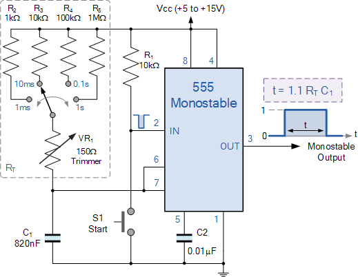 hasty solar
seems like my idea won't work since it adds too much resistance to the discharge path for it to stay discharged in its off state, but this diagram looks like it'll work (with pin 2 separated so i can control the on cycle) by keeping the resistors in series but shorting out the discharge resistor during charging https://www.electronics-tutorials.ws/wp-content/uploads/2019/07/tim72.gif
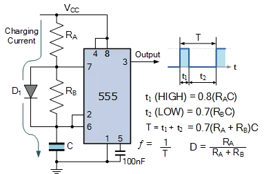 hasty solar
circuit diagram i ended up speccing out - will this work? resistance/capacitance values are semi-arbitrary based on components i have and the range of cycle lengths i wanted
 supple pollen
I don't think that will work, but you can pull the setpoint around with an external voltage into pin 5
After reading your description, it might work depending on what the signal from the moisture sensor looks like. You'll get a lot of emitter degeneration.
limber thunder
if i wanted to do a 4*3 grid of buttons using as few pins as possible, how would i go about it?
there's a way to do it with resistors and an analog pin but i havent found any good concrete info on how exactly it should be done
 drowsy drift
limber thunder
if i wanted to do a 4*3 grid of buttons using as few pins as possible, how would...
drowsy drift
limber thunder
if i wanted to do a 4*3 grid of buttons using as few pins as possible, how would...
The standard way is a key matrix: https://learn.adafruit.com/key-pad-matrix-scanning-in-circuitpython/keymatrix

Adafruit Learning System
Read buttons, keys, keypads, keyboards, and game controllers fast!
limber thunder
drowsy drift
The standard way is a key matrix: https://learn.adafruit.com/key-pad-matrix-scan...
problem is that's like 80% of the pins i have remaining and i still need to wire a display
looks like i can use an i/o expander
drowsy drift
limber thunder
problem is that's like 80% of the pins i have remaining and i still need to wire...
The multiple-buttons-with-analog pin can work but can be finnicky and usually analog pins are precious. Here’s one technique: https://forum.arduino.cc/t/multiple-buttons-on-1-analog-pin/8622

Arduino Forum
Thought i'd share a little project i've been working on. As many may know there is a method for using a single analog pin to control multiple buttons. There is even a library for it. Problem is the way they connect the circuit doesn't allow for the use of button combinations. So you couldn't press 2 buttons at the same time to perform a diffe...
drowsy drift
limber thunder
looks like i can use an i/o expander
Yes! An I/O expander is perfect. For buttons I really like using something like the 74HC165 shift register. Here’s an Arduino example. You can use keypad.ShiftRegisterKeys if in CircuitPython https://dronebotworkshop.com/shift-registers/

Learn to use the 74HC595 and 74HC156 shift registers to add extra input and output ports to your Arduino, then use them to build a fancy LED light display!
supple pollen
You could also use a chip specifically designed to operate keypads
hasty solar
supple pollen
I don't think that will work, but you can pull the setpoint around with an exter...
what component would I use to control the voltage delivered to pin 5? and do you have an article I could read about emitter degeneration?
my hope is to have the 555 tripped when the analog voltage from the moisture sensor goes above some threshold
limber thunder
is this a correct key matrix?
 supple pollen
Yes, but without series diodes you can run into an effect known as "ghosting" if multiple keys are pressed at once.
limber thunder
supple pollen
Yes, but without series diodes you can run into an effect known as "ghosting" if...
dont those go between pin 3 on the buttons and the row wire?
supple pollen
For true ghosting prevention (3 or more keys at once), you need a diode per switch. But a diode per row is sufficient for up to 2 keys at once.
supple pollen
hasty solar
what component would I use to control the voltage delivered to pin 5? and do you...
I had a look around and haven't found any really good writeups. Here's one that gets at the idea, but I don't think it's presented very clearly: http://contents2.kocw.or.kr/KOCW/document/2019/chungang/kwonhyuckin1213/4.pdf
limber thunder
limber thunder
where would the diode go
at the end?
supple pollen
Between the matrix and the GPIO
 limber thunder
supple pollen
Between the matrix and the GPIO
limber thunder
supple pollen
Between the matrix and the GPIO
is KS the input or output
supple pollen
I think that's the side connected to GPIOs configured (one at a time) as outputs?
limber thunder
(dumb question) why would there need to be a diode on an output?
if something goes back into it would it matter?
supple pollen
Good point. I misread your question about pin 3 and the row wire, and mentally jumped to that diagram (which is for a combination LED and keypad driver, which needs the diodes to keep the LEDs from confusing the keypad circuitry). You can omit the diodes if you don't need to prevent ghosting
limber thunder
supple pollen
Good point. I misread your question about pin 3 and the row wire, and mentally ...
itll be one button at a time for this
supple pollen
Then you don't need any diodes
limber thunder
i was trying to pick a ~2.7-3.2" mono backlit lcd but all of them use like 10v
not like one of the super wide rectangular ones but something that's more square but not entirely square
supple pollen
There should be 5V ones that aren't too hard to find
supple pollen
Runs cheerfully on 5V https://www.adafruit.com/product/181

Standard HD44780 LCDs are useful for creating standalone projects.16 characters wide, 2 rowsWhite text on blue backgroundConnection port is 0.1" pitch, single row for easy breadboarding ...
limber thunder
supple pollen
Runs cheerfully on 5V https://www.adafruit.com/product/181
thats one of the super wide rectangular ones
supple pollen
You just gave one dimension and specified mono, backlit, and LCD
limber thunder
not like one of the super wide rectangular ones but something that's more square but not entirely square
supple pollen
How much more square? Like 4x16?
 supple pollen
Character or graphic?
limber thunder
either or
im looking at eink displays but none of the ones im seeing come with frontlights
supple pollen

Newhaven Display
Newhaven 4x16 character Liquid Crystal Display shows characters with dark pixels on a bright yellow/green background when powered on. This transflective LCD Display is visible with ambient light or a backlight while offering a wide operating temperature range from -20 to 70 degrees Celsius. This NHD-0416BZ-FL-GBW display has an optimal view of 6...
Winstar, Crystalfontz, New Haven Display, 4D systems, lots of vendors offer them
Or if you like the look of VFD displays, this Noritake CU20045-UW7J has a display area of 73.6 x 40mm https://www.noritake-itron.com/site2024/downloads/CU20045-UW7J/image.jpg
 limber thunder
supple pollen
Or if you like the look of VFD displays, this Noritake CU20045-UW7J has a displa...
limber thunder
supple pollen
Or if you like the look of VFD displays, this Noritake CU20045-UW7J has a displa...
that is so cool
they are not cheap lmfa
it's like $130
supple pollen
Yow. I have a bunch of their smaller ones, they were like $20. Not sure why that one is so expensive.
limber thunder
do you know where you got them?
supple pollen
I think I got them directly from Noritake. I miss these days: https://www.adafruit.com/product/347

One up your plain old character LCD with a gorgeous VFD! These displays look and act just like character LCDs but are way glowier, and are very readable even from a distance. As a bonus, you ...
Looks like prices have gone way up. The CU16025 I used to buy for $20 is over $80 now
supple pollen
Ali has some: https://www.aliexpress.us/item/3256803148560467.html
limber thunder
i wish they werent all that aspect ratio but tbh that's a price im willing to pay
this was originally going to be a bit more phone shaped
supple pollen
I have some that aspect ratio and size, but they're giant 1 and 2 character displays, really low rez
There are some 16x4 LCDs on Ali for worryingly low prices (55 cents for this one): https://www.aliexpress.us/item/2251832625972718.html
limber thunder
most of the cost is the controller it seems
supple pollen
There are some nice looking little OLED displays too: https://www.aliexpress.us/item/3256806677479031.html
limber thunder
every single ounce of my being wants me to stick to vfds
supple pollen
I'm now really glad I bought a boatload of them when they were cheap
limber thunder
istg i was born in the wrong year
:(

The most iconic calculator for me is Elektronika MK-54, or MK-61. MK-52 to a lesser degree, because it came out so late and I never had a chance to actually use it. In the mid-80s, alone in the summer at a country house I spent countless hours on MK-54 playing lunar lander and displaying various things it shouldn't display. Actually it ate throu...
if i can find an oled with that blue-turquoise-ish tint im seeing on the vfds it would be perfect
supple pollen
Might be able to manage it with a color filter
limber thunder
supple pollen
Might be able to manage it with a color filter
who makes those?
im not opposed to the idea
supple pollen
Yes. It totally is. Wait 'til you get hooked by cathode ray tubes...
 limber thunder
supple pollen
Yes. It totally is. Wait 'til you get hooked by cathode ray tubes...
limber thunder
supple pollen
Yes. It totally is. Wait 'til you get hooked by cathode ray tubes...
i already had a crt phase
supple pollen
I normally get my filters from Lee Filters
limber thunder
https://leefilters.com/lighting/colour-effect-lighting-filters/
which color would you say is closest to that of a vfd
LEE Filters
For 50+ years, LEE have supplied high-quality lighting filters in a vast range of colours. Always consistent, long-lasting, & dependable. Find out more.
supple pollen
That's the tricky bit: it depends on what color OLED you're starting with
limber thunder
wouldnt white be the easiest?
supple pollen
White is probably your best bet
What I'd probably do is get one of their Cinegel swatch books ($10 or so) and try various ones (and combinations - stacking gels gives you a lot more color choices). The swatches may be big enough to use directly with your display.
limber thunder
that isnt lee. still the correct one?
supple pollen
Oh right, that's Rosco. Another big color filter vendor, they're good too.
limber thunder
wouldnt the filter make the background look blue as well as the light?
supple pollen
Yeah, but the background is dark (darker with the filter) so it's not terribly obvious. And using VFDs with filters was very common.
limber thunder
supple pollen
https://www.bhphotovideo.com/c/product/45184-REG/Rosco_950SBCNG0103_Cinegel_Swat...
so if the swatches here are big enough i can just apply them? idk how that works
supple pollen
Yup. That's totally valid.
limber thunder
how do they adhere to the display?
supple pollen
Got the pointer to Lee on this Discord while a while back #general-tech message
Attaching them is left as an exercise for the user
You can use double sided tape, clamps, covers, etc.
supple pollen
Yup. Saw a $2 one I like the look of
limber thunder
do i want to change the shape of the entire device just for a vfd though
supple pollen
That depends on your design priorities
limber thunder
it was originally gonna be a phone lmao
supple pollen
It's easier to put a VFD in than try to find room for a CRT but still...
limber thunder
do i want it to be the coolest stuff ever or do i want it to be phone shaped
supple pollen
I remember the old Motorola brick phones with an 8-digit LED dot matrix display
limber thunder
this might be the first rp2040-based phone
putting a vfd in it would just make it even funnier

(ignore the swag rat)
supple pollen
Have you seen the CircuitMess phone? https://learn.circuitmess.com/ringo/

I don't recognize that phone module offhand. I do rather like the rat.
limber thunder
supple pollen
I don't recognize that phone module offhand. I do rather like the rat.
the thing in the bottom left you mean?
that's the ec25
it's an expensive chip but it does sms and calling
as well as 4g lte
supple pollen
Lots of them do SMS and calling, but yeah, 4G is more expensive than 3G
limber thunder
supple pollen
Lots of them do SMS and calling, but yeah, 4G is more expensive than 3G
you need a specific class of chip and this was one of the cheaper options
most of them are only data, no sms or calling
supple pollen
I was looking at something like the SIM-7600
limber thunder
yeah the ec25s are around $70
so far the features i have are: a lion battery setup (which i might need to change later), an rp2040, buttons (which i will need to change if i use the vfd), proper hifi audio (lmao) and that's pretty much it
i might need a microsd reader (the ec25 has one built in but idk if i can access it using the uart commands)
havent bothered to check
if i went with this display what shape would the rest of the device be
 supple pollen
There are several possibilities.
limber thunder
im kinda at a loss
supple pollen
I'd be tempted to use an ordinary bar format, with the display in the middle, vertically, with the speaker above it and the mic below
limber thunder
what abt buttons
supple pollen
Several possibilities. You could have a keypad between the display and mic, or columns of buttons flanking the display, or get creative and have the buttons on the side or back (I'd have a few on the side anyway for volume and the like)
I'm thinking old school phone style
 limber thunder
that's a really cool idea tbh
supple pollen
You could also get fancy and hide the mic between the buttons (it's just a little opening)
limber thunder
i wanna see how big 7cm is holdon lemme find my ruler/caliper (whichever turns up first)
can the characters on these displays display vertically?
supple pollen
It would be tempting to grab one of those old school phones and build an updated one into it and reuse the buttons and display, but those old school phones seem to have become expensive collectors' items (even though you can't use them these days)
limber thunder
i was gonna 3d print a shell
supple pollen
Although the one pictured is only $60 on eBay (unlike one I saw for a whopping £33k)
limber thunder
wow that display is really small
supple pollen
Big displays weren't really a thing in those days
limber thunder
7cm is tiiny
supple pollen
Could fit this in there https://www.aliexpress.us/item/3256803088819955.html
... maybe
limber thunder
wait why are these so expensive
what step in the production makes them so pricey
i guess supply & demand
supple pollen
$2 is too rich for your blood?
limber thunder
im talking about the larger ones
supple pollen
Could be the power converter: it needs to create a low AC voltage for the filament and a moderate (like 30V) DC voltage for the grids and anodes. Also the control electronics also has to deal with 30V outputs.
limber thunder
its a shame tbh
supple pollen
The VFD module itself requires phosphors, cathode activation, vacuum processing, gettering, etc.
Some creative folks repurposed VFD technology to make a flat glowing triode amplifier tube http://www.nutube.us/
limber thunder
https://www.amazon.com/Onkyo-TX-NR696-Receiver-Compatible-Enabled/dp/B07STXVRRP
what kind of display is this

Onkyo TX-NR696 Home Audio Smart Audio and Video Receiver. Future-ready home entertainment with THX Certified Select. A harmonious mix of tech and tradition, the TX-NR696 adapts to entertainment life and finds the emotion in every sound source, from 3D film-scores to vinyl records. With revitalize...
it almost looks similar to a vfd
supple pollen
I suspect it is VFD
limber thunder
on a receiver that modern?
supple pollen
Some folks like the look of it, and audio equipment design doesn't change very fast
limber thunder
i think we have one spare - could probably yoink it
supple pollen
Used equipment is a great source of VFDs. You may have to come up with your own drive electronics, but there are chips and power supplies available
 limber thunder
supple pollen
limber thunder
supple pollen
Yow, that is a nice find!
supple pollen
One of the related items seems to have the controller but it's $78
limber thunder
limber thunder
supple pollen
One of the related items seems to have the controller but it's $78
yeah the ics im seeing are like 5 bucks
you can solder vfds straight onto boards right?
supple pollen
Yup.
The far left one in the pic above is taken out of a microwave oven and soldered to perf board for an art project I'm building (working title: "Blinking 12:00")
limber thunder
limber thunder
maybe https://www.analog.com/en/products/max6921.html
would this chip work?
wow i need some very steppes up voltages
supple pollen
Yeah, that's a good chip
limber thunder
so i gotta step lion voltages up to what like 60v?
that sounds like a current eater
supple pollen
There are a few ways to get the voltage. The LM9022 chip is designed to create both the filament and drive voltages, or you can use a voltage multiplier, step-up transformer, boost converter, or pre-built power supply module
30V is plenty for most of these
limber thunder
the vfd wants like 45
supple pollen
These days, a boost converter is probably the easiest approach
The board with the microwave display in the picture has a handy little VFD power supply module under it, that I got from a surplus electronics vendor. It provides both the center tapped AC voltage for the filament and the higher voltage for the grids and anodes.
limber thunder
limber thunder
the vfd wants like 45
it doesnt have a minimum listed, typ is 45 and max is 50
supple pollen
This display data sheet includes a schematic for a power supply https://cdn.hackaday.io/files/1916648200152576/EPC-INBN0BV1294UD_SPEC.pdf
supple pollen
It's a big ratio, the popular choices are the ancient 555 timer, MAX1771, and MC34063
There's a diagram on this page for a 45-190V supply: https://threeneurons.wordpress.com/nixie-power-supply/hv-supply-kit/

High Voltage Power Supply Kit Go to Bottom of page to download PDF file of NK01A & NK01B instructions: This kit allows you to build a regulated switch-mode power source, that will convert a, no…
limber thunder
supple pollen
It's a big ratio, the popular choices are the ancient 555 timer, MAX1771, and MC...
the max only seems to do 12v?
supple pollen
It can do considerably more: https://desmith.net/NMdS/Electronics/NixiePSU.html
limber thunder
the mc34063 looks like itll work
so any input voltage can result in any output voltage on there or are there limits to the stepping up
supple pollen
There are limits, but getting 45 or even 60 volts from a lithium cell is fairly straightforward
limber thunder
supple pollen
There are limits, but getting 45 or even 60 volts from a lithium cell is fairly ...
wow
can i do 40v on the vfd?
supple pollen
Personally I like the LT107x and LT117x chips, but there isn't as much info out there on using them, as they work differently and are more expensive.

40V should work. For testing, I'll often just use three cheap 9V batteries in series for 27V. My preferred source for cheap 9V batteries is a dollar store.
limber thunder
supple pollen
Personally I like the LT107x and LT117x chips, but there isn't as much info out ...
the 1070 could probably work too
how much current would lion voltage to 45v draw
supple pollen
It depends on how much current is drawn at 45V
limber thunder
30ma it looks like
supple pollen
Basically it'll be about 11 times the draw, so if you're drawing 5mA at 45V, you'd probably be drawing 60mA or so at 3.7V
limber thunder
supple pollen
Basically it'll be about 11 times the draw, so if you're drawing 5mA at 45V, you...
yowza
supple pollen
30mA out would be 350 or so mA in
limber thunder
i might need a different battery
supple pollen
It's the law of conservation of power
limber thunder
mine can do like max 3a out safely
the cellular chip peaks like 2a but ill probably only be doing up to 1a max because no high speed data transfers needed
supple pollen
30mA at 45 volts is 1.35 watts: no matter what you do, you'll need to start with at least that much power (generally a little more due to circuit losses)
limber thunder
supple pollen
30mA at 45 volts is 1.35 watts: no matter what you do, you'll need to start wit...
that shouldnt be a problem right?
supple pollen
No, that's a reasonable load for battery operation
Lots of useful info here: https://www.noritake-elec.com/technology/general-technical-information/vfd-operation

Noritake Co., Inc. Electronics Division
Learn about the technology behind Noritake VFDs (Vacuum Fluorescent Display). Explore display construction, signal timings, and the grid and anode power supply.
limber thunder
and then with everything else on top of it?
supple pollen
I'm not sure which lithium cell you have in mind, but lots of them are capable of that kind of power delivery
limber thunder
it does 3a maximum current draw
supple pollen
Should be sufficient
supple pollen
Yup.
limber thunder
@supple pollen how do i set the voltage of the lt1070
they have examples on certain voltages but none are what im looking for
supple pollen
In the diagram above, the resistors to the feedback pin form a voltage divider. The idea is to adjust the ratio so when the output voltage is the voltage you want, the feedback pin voltage will be 1.24V
There's a very good application note that explains all of this: https://www.analog.com/media/en/technical-documentation/application-notes/an19fc.pdf
The equation you want (and the explanation of how to choose resistor values) is on page AN19-18, equation 21.

 supple pollen
R2 is 1.24kΩ, and R1 is calculated from it. Since it's a ratio, it will work either way.
That looks right, that would make R1 43.6kΩ
I normally do all my calculations in basic units to avoid such confusion
limber thunder
i can do 43.7 but not .6
that's close enough
does it matter what power the resistor iss?
supple pollen
Only about 1mA is flowing through it, so power dissipation shouldn't be much of an issue. 45V times .001A is only 0.045 watts.
The VFD isn't going to care if it's 44V or 46V, so the tiny error in the calculated resistor value isn't going to matter.
The data sheet for the LM9022 VFD power supply chip shows another approach using a voltage multiplier: https://www.farnell.com/datasheets/67785.pdf
limber thunder
it looks like the inductor should be approx 150uh, same as what the doc says
i find that weird because im using very different values but whatevs

 supple pollen
It looks like a lot of the terms more or less cancel out in your use case, so it makes sense that the value doesn't vary much.
limber thunder
https://www.digikey.com/en/products/detail/bourns-inc/SRR1210-151M/2562345
would this work as an inductor?

DigiKey Electronics
Order today, ships today. SRR1210-151M – 150 µH Shielded Drum Core, Wirewound Inductor 2.2 A 190mOhm Max Nonstandard from Bourns Inc.. Pricing and Availability on millions of electronic components from Digi-Key Electronics.
supple pollen
That seems suitable to me