#help-with-hw-design
1 messages · Page 28 of 1


 coarse lark
pinout numbers and front silkscreen are done!

yess!

its pretty much finished, just need to add the bottom silkscreen and its done
 pale grove
Flex PCB question.
When I research for min. bending radius it usually says 6-10x the FPCV thickness. (Which would mean at least 0.6-1 mm bending radius)
But I took a couple of wearable electronics apart and in many of them there is pretty much no bending radius? It would be folded straight down in a 90° angle or in some cases 180°
Is there a reason for that/where can I read up on that?
 inland jungle
is there anyplace the "ruggedizes" or "industrializes" MCU boards and/or sensor boards?
 novel gate
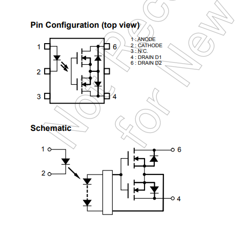
I have a question about solid-state relays, I'm looking at https://files.nurdism.dev/u/2B9YhI.png I has D1 and D2, when I provide power to the relay, does it switch the power from D1 to D2, or does it connect D1 and D2 together.
What I am trying to figure out is with a standard relay, there is an "off" position and an "on" position, but it can be used to toggle between 2 circuits like this https://www.tinkercad.com/things/bjVKRBsjo41-tremendous-migelo?sharecode=GSxRx6HjDHsU8cbEB5p81ilcFV4y7oqV6gvS0duZWMI
What I have in my head I could use D1 and D2 to switch between 2 circuits with a shared ground on pin 5. Like this https://files.nurdism.dev/u/qAC9vl.png, I'm attempting to make this https://www.tinkercad.com/things/df0s6yPbcUe-arduino-relay-continuity-detection-circuit but on a pcb with with solid state relays and a MCP23017.
What I am asking is, am I misunderstanding how the solid-state relay works? Is there a good resource to help me understand how they work? Sorry if this is not the right place to ask this.

Tinkercad
Circuit design Arduino "Relay Continuity Detection" Circuit created by nurdism with Tinkercad
 latent jungle
novel gate
I have a question about solid-state relays, I'm looking at https://files.nurdism...
latent jungle
novel gate
I have a question about solid-state relays, I'm looking at https://files.nurdism...
When activated, D1 and D2 are effectively connected together, like a mechanical switch. There is no “pin 5.” There is no accessible common point between them.
novel gate
ah ok I see, so in this case a relay would be a better solution?
 green wadi
So a load switch would be the cleanest option here?
coarse lark
ta-da! its finished

 jade wedge
I'm thinking of trying to do wheel sensing (not precise) by putting a magnet on the wheel, and having it pass past a wire that runs between two pins of an MCU. Specifically an analog out (not PWM, but proper DAC), and analog in. The idea being that I can use the DAC to put a known voltage on the line, and the magnet passing by will either increase or decrease the voltage that the analog in sees.
I should be safe doing that, right? Also, this should work roughly how I'm envisioning it, right?
I'd use a proper hall effect sensor, or optical sensor, except this is for a pair of roller blades, and space is at a premium.
 knotty tiger
green wadi
So a load switch would be the cleanest option here?
knotty tiger
green wadi
So a load switch would be the cleanest option here?
probably. some loads might tolerate the glitch. sometimes, especially with default 5V VBUS, the glitch might exceed the maximum inrush current allowed by the USB 2.0 spec
coarse lark
is this ok for a 4x4 neopixel matrix?

 worldly schooner
coarse lark
is this ok for a 4x4 neopixel matrix?
worldly schooner
coarse lark
is this ok for a 4x4 neopixel matrix?
I don’t know about putting 10uF capacitors per pixel, as there is such a thing as “too much capacitance.” Most of the PCBs I’ve seen use 1uF per, including those provided by Adafruit.
worldly schooner
jade wedge
I'm thinking of trying to do wheel sensing (not precise) by putting a magnet on ...
That would depend on the speed of the ADC vs the rpm of the wheel. If the ADC isn’t fast enough, you’re not going to get great results. A 3-pin hall effect sensor would be much more reliable for this type of encoder application.
Something akin to https://www.adafruit.com/product/158, for your reference.
jade wedge
Hmm, good point. Asking google (since I'm too lazy to math right now) at 10 mph it's only doing about 100rpm though, so measurement time likely wouldn't be a problem. The other reason for trying to avoid a discreet sensor is that to determine direction I need two and some fancy math.
Though I'm not sure how much of a variance a single magnet passing by a single wire would even impart on the voltage.
worldly schooner
Precision of your adc may also be an issue. With the space restrictions given, you might not get a detectable rise or fall in current without significant amplification or more loops of wire.
jade wedge
10bit ADC in the ATTiny1616
But I guess the core answer that I was looking for is "it won't blow anything up, but it may also not work due to other reasons"
Which is fine. It's a long shot and a weird solution to the problem. As long as I don't damage anything, trying an idea that fails doesn't bother me much.
Hmm... Also something doesn't sit right with these numbers.
Yeah. It's not 100rpm, it's 1000. I think?
Eh. These are questions for elsewhere.
coarse lark
worldly schooner
I don’t know about putting 10uF capacitors per pixel, as there is such a thing a...
Hmmm ok
Ill change them
worldly schooner
pale grove
Flex PCB question.
When I research for min. bending radius it usually says 6-10...
Something like https://www.hemeixinpcb.com/company/news/425-how-to-calculate-the-flex-pcb-bend-radius.html perhaps. While the bend radius is a good metric to follow for longevity’s sake, a one-time crease will permanently deform the flex pcb. In applications that use such a feature, that only means there is an expectation of some irreversible strain on the pcb, but the design ensures it still works despite that.
Repeated creasing and unfolding of a flex pcb, on the other hand, will undoubtedly cause layers to break and/or delaminate.
Flex PCBs offer flexibility and rigidity. But how much can they bend? This article will teach you how to calculate the flex PCB bend radius.
 tribal quartz
Hello! about to go to bed but i'm dropping a hardware question in here just in case I can get some guidance 😊 I have a foundational understanding of boards and can get to a point of understanding with enough reading and clarification but by no means a hardware engineer
just want to make sure i'm understanding things correctly for a modification im trying to do with an arcade stick for fighting games 😈
so i own a custom fight stick with this board https://focusattack.com/template/download/brook/manual/UFB-Fusion-User-Guide.pdf and would like to modify if for seamless playstation 5 compatibility
there are market converters but they're rather pricey so a friend familiar with this fight board and controller modifications recommended this micro adapter https://www.mayflash.com/product/MAGPS4.html
Provide the best solution when you must connect a wired PS4 controller with your Joystick or FPS gaming adapter when you use it on a PS4 game console.
according to the user guide, i believe the board has components that would allow me to connect a usb breakout cable so i can connect the mayflash via the J6-1 connector, and i just want to make sure i'm interpreting the guide clearly
the J6 connector is a usb b cable that allows the arcade stick to connect to PC/consoles, and i'd rather not mess with that bit since i'm happy with it as is
pale grove
worldly schooner
Something like https://www.hemeixinpcb.com/company/news/425-how-to-calculate-the...
I guess it's the "one time crease" option then that many products are using
latent jungle
tribal quartz
the J6 connector is a usb b cable that allows the arcade stick to connect to PC/...
J6 looks like a USB-Device connector. The MAGPS4 looks like it requires a USB-host port. But it is very unclear to me what that dongle does.
tribal quartz
latent jungle
J6 looks like a USB-Device connector. The MAGPS4 looks like it requires a USB-ho...
the MAGPS4 is meant to resolve issues with backwards compatibility for older controller hardware on the ps5 console, even if its only one gen back. The UFB fusion essentially acts like an officially licensed ps4 controller. unfortunately, on the ps5, if you play a ps5 copy a game, it will not function with ps4 controllers. most official tournaments and events provide only ps5 copies of games for free play. alternatively since there's no issues with backwards compatibility for the game software itself, playing a ps4 copy of a game on the ps5 is the only way for this controller board (and most other custom ps4-based boards) to work without issues.
the need for either expensive converters or just getting a new controller altogether has been a lingering issue for a while in the fighting game community 😅 so i'm trying to tinker around and find a solution that lets me keep my current stick but still lets me play without worried about the kind of game copies that are available
latent jungle
Well, that doesn't clear up what the dongle actaully does. But I suspect it's meant to plug into a host port and not a device port. The UFB's page nor manual seem to mention anything about plugging in a PS4 controller into it. Seems like its USB device port is meant to plug it into another host (like a PS4 or PC.)
tribal quartz
it's meant to plug into a controller, i know for those who have controllers with RP2040s, they use GP2040-CE firmware for "universal" controller compatibility, and plug the dongle into the usb port on the board, then connect to consoles or PCs with a usb-c port on the other end
HOW the dongle does what it does, i'm not sure! sorry i can't give more exact context

SGF Devices
New USB Passthru Edition! Supports PS5 with the use of the Mayflash Magicboots v1.1 or Brook Wingman FGC Note: Only fighting games supported on PS5. Without the use of Magicboots/Wingman (or similar authentication device), the PCB will time out after 8 minutes of use on PS4 or PS5. Regular PS5 controllers will not work
this would be an example of the other kind of board i just mentioned
latent jungle
Okay, but that's very different. It clearly has host and device ports on it. The first one doesn't. I don't see how that first board would plug into a controller since most controllers don't have a USB-host port on them.
I'm sorry, but this is just too confusing to me. I'm clearly missing something.
tribal quartz
not at all! I appreciate just having you hear me out 🤗 my question for being able to do something similar for ps5 passthrough with the dongle on the board i do have is if at the j6-1 connector (not J6 since that is in use), i can connect in a usb port cable; would that connector be appropriate for installing a usb host port myself? on the UFB user guide on page 6, it looks like i can add something like this product there

If you'd like to connect a USB-host-capable chip to your USB peripheral, this cable will make the task very simple. There is no converter chip in this cable! It's basically ...
if the j6-1 connector could have that part installed there, i think that would allow the dongle to connect to my board, but i'm not certain based just on the picture there if that would be possible since the picture has a male usb part in the guide
if the confusion is what the board does, the board IS the controller! i can share pictures of how mine is set up if that helps as well
latent jungle
Yes, you could attach that cable. But nothing in the documentation for that first board suggests it is meant for a USB-device to be connected. It only shows the opposite, using that header for a USB-A host connector, to connect to a host.
I’m quite certain J6 does not do what you think it does.
Do you understand the difference between USB-host and USB-device?
tribal quartz
i understand that devices are the peripherals themselves, and hosts are meant to recieve information form them, right?
latent jungle
tribal quartz
i understand that devices are the peripherals themselves, and hosts are meant to...
Yes. USB has roles. A device can be a host or a perheripals. (I said host/device earlier, it should have been host/perpherial for clarity.) Except for OTG (on-the-go), a single USB connection can only be one or the other. That first board you sent has a peripheral USB-B socket connector on it, indicating it is a peripheral. The small dongle has a USB-A plug connector indicating it is a perpherial. Two perpherials cannot be connected together.
Further, J6 and J6-1 are very likely connected together. You can only have one host and one perperhial on one bus.
tribal quartz
aahhh i see, this makes sense, that was exactly what i wasn't sure about. i think this clears up what was going on with the connectors on the board, thank you for the clarification!
 subtle crater
Hi, I have two LiPo batteries with integrated protection modules and I want to balance their charges at the flick of a switch. Can I literally just connect positive to positive and negative to negative, or is there something else I should consider?
 cursive sentinel
That depends on what the protection modules actually do, but I'm gonna go with "probably not"
latent jungle
At best, they'll discharge each other without achieving a balance.
Even a small value (high power) balancing resistor would help.
 amber raven
So, I've been experimenting with dc load circuits utilizing mosfets as a way to dissipate energy. I've been using this design for a while and I'm currently testing out a prototype of this design before moving on to a greater scale. My test consists of using 2 power supplies acting as a LOAD and VCC. the LOAD is adjusted to 12V while the VCC is adjusted to 24V. The ground of both - and GND is connected. While doing some experiments however, somehow my mosfets couldn't pull more than 2A and 6V and somehow adjusting the load power supply beyond around 6-10V would only decrease the current it pulls, contrary to my simulations using proteus. Does anyone know what's wrong with my design and how to fix it? Here are the designs im using and the datasheet for the MOSFETs that im using.


 supple pollen
amber raven
So, I've been experimenting with dc load circuits utilizing mosfets as a way to ...
supple pollen
amber raven
So, I've been experimenting with dc load circuits utilizing mosfets as a way to ...
How hot are they getting?
amber raven
supple pollen
How hot are they getting?
they're not even getting hot
supple pollen
Having the current go down when the voltage goes down is expected (Ohm's law), no idea what Proteus is thinking.
You could be running out of gate voltage, since you have your circuit wired using source degeneration (in other words, the gate voltage is the difference between the gate and source: as current flow increases, the source voltage increases due to the increasing drops across the source resistors.
 plucky citrus
id like to stack a bunch of feathers and im looking for a standoff/screw set to go with it
aare they just m3s
amber raven
supple pollen
Having the current go down when the voltage goes down is expected (Ohm's law), n...
the current goes down when the voltage goes beyond a threshold
so like if i go above around 6 or 9v, the circuit would draw less than the previous 2A
so it's like a hill or some sorts
amber raven
supple pollen
You could be running out of gate voltage, since you have your circuit wired usin...
how do you fix this?
knotty tiger
my first instinct is that you have the +/- inputs on your op amp reversed, but i’d have to stare at it more and do some math to be sure
amber raven
knotty tiger
my first instinct is that you have the +/- inputs on your op amp reversed, but i...
i tried reversing the input, it only makes the potentiometer do the opposite when turned to the same direction as the previous state
 gloomy lion
I'm seeing that the ESP32 has a lot of strapping pins that need to be pulled a certain way during boot, like IO2 needing to be low and and IO0/15 needing to be high. If I'm using an ESP32-WROOM-32 module, do I need to explicitly pull these high with external pullups, or can I leave them unconnected and rely on internal pullups?
supple pollen
amber raven
how do you fix this?
It depends on how you want to do things. You could reference the op-amp supply negative rail to the top side of the source resistors. Or you could use lower-value source resistors and more gain. Or you could use a higher op-amp supply voltage. It depends on your preferences/requirements.
gloomy lion
gloomy lion
I'm seeing that the ESP32 has a lot of strapping pins that need to be pulled a c...
In case anyone's searching in the future, looks like the datasheet answers this! Couldn't check it earlier thanks to limited cellular data
Each strapping pin is connected to its internal pull-up/pull-down during the chip reset. Consequently, if a strapping pin is unconnected or the connected external circuit is high-impedance, the internal weak pull-up/pull-down will determine the default input level of the strapping pins.

To change the strapping bit values, users can apply the external pull-down/pull-up resistances, or use the host MCU’s GPIOs to control the voltage level of these pins when powering on ESP32.
coarse lark
any recomendation for ESD protection diodes for USB?
latent jungle
coarse lark
any recomendation for ESD protection diodes for USB?
I recently used the BZA856AVL in a design. I liked how easy it was to route.
coarse lark
planning on adding that for my next boards that incorporate usb
just realized this morning how destructive ESD's could be
so to keep my circuits safe im adding more safety features
latent jungle
The most insidious thing about ESD is that damaged components do not always fail immediately.
supple pollen
Sometimes they don't fail at all, just get flaky or intermittent. Or waste energy and generate heat. Or cause something connected to them to misbehave. Or all of the above and then some.
amber raven
@supple pollen some designer friends suggested me to add a push pull driver to the gate, would this change anything?

this one
so the PWM signal would be attached to the op-amp instead
Also, changing the MOSFET somehow fixed the issue yet I encountered another problem
if i decrease the voltage of the op amp's output, it will reach a certain point where it would lock onto a low voltage and deactivate the mosfets
why is that?
supple pollen
PWM? I figured this circuit was running the MOSFETs in linear mode.
I don't know what you mean by "lock onto a low voltage"
knotty tiger
is there some reason the bidirectional 74AHCT245 is preferred over similar unidirectional level translators even for unidirectional applications like HUB75?
like why not the ‘244 or ‘241?
cursive sentinel
None that I see. Might just be due to availability.
supple pollen
Or an easy to route pinout
coarse lark
so i was making a mega variant of my previous board, with a neopixel matrix and other stuff, but in the end i wasnt satisfied with it so i took a small break, in the end i decided to leave that one to the side and make an even smaller S3 dev board, this time a lil dongle thing

in upcoming projects i wanna be able to use the S3 chip instead of the entire module
oh also, stemma qt/qwiic was a 4-pin 1mm SH connector right?
planning on adding that
coarse lark
is it done like this?


 distant raven
coarse lark
is it done like this?
distant raven
coarse lark
is it done like this?
You can reference the Adafruit designs to validate
coarse lark
distant raven
You can reference the Adafruit designs to validate
i think i did it correctly


yeah
yeah this is it, i checked here with the Metro S3 and i can also see the pullup resistors
 amber raven
supple pollen
PWM? I figured this circuit was running the MOSFETs in linear mode.
amber raven
supple pollen
PWM? I figured this circuit was running the MOSFETs in linear mode.
the pwm will be changed with a linear working op amp circuit instead
amber raven
supple pollen
I don't know what you mean by "lock onto a low voltage"
basically when i measure the gate voltage of the mosfets it would jump from some value like 7 volts to 1.4 volt and it won't increase more than that until i "reset" the drain voltage
as if it were a failsafe or something
coarse lark
aadded the Stemma QT thing and also i added some test points, for good practice

cleaned it up
 supple pollen
coarse lark
is it done like this?
supple pollen
coarse lark
is it done like this?
I'll often add cuttable/solderable jumpers to disable the pull-up resistors.
coarse lark
supple pollen
I'll often add cuttable/solderable jumpers to disable the pull-up resistors.
hmm? why is that
supple pollen
amber raven
the pwm will be changed with a linear working op amp circuit instead
It's a big difference. You don't need a high current gate drive if you aren't trying to run high frequencies into the gate.
supple pollen
amber raven
basically when i measure the gate voltage of the mosfets it would jump from some...
Gate voltage compared to what? Ground? The current measuring resistor? The source pin? Something else?
supple pollen
coarse lark
hmm? why is that
If you hook too many I2C peripherals with pull-ups to the same bus, it can cause problems, so making it easy to disable the pull-ups can come in handy.
amber raven
supple pollen
Gate voltage compared to what? Ground? The current measuring resistor? The so...
ground
so it's just Vg
not Vgs
coarse lark
supple pollen
If you hook too many I2C peripherals with pull-ups to the same bus, it can cause...

seems like a good idea, but i dont have enough space for that
i will be adding a jumper for the neopixel tho
supple pollen
Yeah, your design is pretty compact, so leaving out extras like that is reasonable
supple pollen
amber raven
so it's just Vg
It's a weird little circuit, with the source degeneration, which may be accounting for the odd behavior of Vg appearing to move (because Vs also moves)
amber raven
what do you mean?
coarse lark
supple pollen
Yeah, your design is pretty compact, so leaving out extras like that is reasonab...
there is not enough space for the debug pads 😔
supple pollen
amber raven
what do you mean?
Pretty much what I said, the conduction of the transistor depends on Vgs, but Vs depends on the conduction of the transistor, leading to some odd feedback effects
coarse lark
supple pollen
Yeah, your design is pretty compact, so leaving out extras like that is reasonab...
ok update, i changed the position of some components and ive got plenty of space now, also since the solder pad for the neopixel didnt fit i decided to do it the S3 QTPY way by powering the neopixel through the GPIO

this way there is no need for a pad, no pad = more space
supple pollen
And a little solder jumper can be tiny, like 1.5mm square
coarse lark
i still think i can do better, and maybe get even more efficient space usage
supple pollen
I tinker with my layouts endlessly, trying to optimize for space, usability, elegance, and visual appeal
coarse lark
supple pollen
I tinker with my layouts endlessly, trying to optimize for space, usability, ele...
OOH I DID IT!
i managed to add all uart test pads and the solder jumper
yeah i also try to go for that
making my boards look and feel good
coarse lark
turns out i made a design mistake, i put the sd card reader right below the antenna, fortunately i can just lower my components and it fits now
coarse lark
this was the most complex board ive done, but at the same time quite fun, now that the main board is done i can now make all the silkscreen stuff and get it ready for manufacturing.

 supple pollen
What does the jumper do?
coarse lark
supple pollen
What does the jumper do?
power the neopixel
the VCC-GND YD ESP32S3 board i have as a reference does it as well
the jumper is quite large so ill make it a bit smaller
also, from the Metro S3

i saved so much space yesterday that i was able to add the jumper,
 supple pollen
That's adorabubble. I suppose you could rotate it 45° so the traces are in line, but that may be a bit silly.
coarse lark
supple pollen
That's adorabubble. I suppose you could rotate it 45° so the traces are in line...
yeah too silly for me, however ive thought of some wacky designs for future boards
supple pollen
Thought experiments are fun and useful
coarse lark
But for example, i thought of making the C variant of my DX32 board a cube made out of 6 pcb panels like a papercraft
And these are joined with solder
And castellated holes
supple pollen
I used to make boxes out of PCB material, but usually it was a solid ground plane on at least one side for shielding
 restive gorge
(just curious) is there any convenient tool to work with both schematics and stripboard layout? I've looked at diylc and veecad - they both seem a bit.. inconvenient
coarse lark
supple pollen
I used to make boxes out of PCB material, but usually it was a solid ground plan...
How resistant were they?
supple pollen
This was low level GHz band signals, they worked surprisingly well
gloomy lion
coarse lark
this was the most complex board ive done, but at the same time quite fun, now th...
I'm no expert by any means but it might be worth either extending the copper keepout zone to the left and right of the antenna as well, or moving the edge of the board back so that the antenna hangs off the end, just for the sake of signal integrity and stuff
Your design would work fine as-is but I've been advised that it's good practice to keep the antenna as far away from everything else as reasonably possible
coarse lark
gloomy lion
I'm no expert by any means but it might be worth either extending the copper kee...
Oh my god
Youre right
I messed up
gloomy lion
You already order the boards?
gloomy lion
Ohhh gotcha
coarse lark
Ill have to pray there arent any performance issues
gloomy lion
I did the same for a board I designed a while back. Works perfectly fine! The range might be a bit shorter but I never noticed any issues
coarse lark
Thank you so much for pointing it out tho, i modified the keepout zone because the DRC kept screaming at me due to the mounting holes on the previous board
gloomy lion
Ahhh makes sense haha
coarse lark
Next time ill make the keepout zone go around the holes
coarse lark
gloomy lion
Ahhh makes sense haha
fixed

 gloomy lion
Sweet!
coarse lark
Now the only things missing are the silkscreen details
 pulsar plover
I was told to repost this here
I’m trying to put a project together basically going from a 3.7 v battery to 8v 15w max with the possibility of charging over usb c and trying to figure out what products would be the best for this purpose
[2:41 PM]
What channel would it be best to post in for feedback?
[2:46 PM]
https://www.fysetc.com/products/raspberry-pi-cm4-hmi-display-module-small-and-high-resolution-him-dpi-interface-capacitive-touch-screen-module
This is what I am trying to power if that helps context wise

FYSETC OFFICIAL WEBSITE
Raspberry Pi CM4 HMI Display Module Small and High Resolution HIM DPI Interface Capacitive Touch Screen Module About the Product: This is a solution that integrates the capacitive touch screen and the Raspberry Pi computing module. In the only 56x97 size, it integrates 4 flexible USBs (2 on the side and 2 on the board)
https://www.adafruit.com/product/2030
https://www.adafruit.com/product/4090
https://www.amazon.com/Converter-DROK-Voltage-Regulator-Transformer/dp/B01L90B3RI/ref=sr_1_8?crid=1L358SF1BMS2O&dib=eyJ2IjoiMSJ9.bOZOcLQw2pbyaB3VttmVSXNsUA5vtjrZaV_tBXPeOdijjkBHEiWPcrlQlohJd_yKt5hRci9zra6fUnA9Of38uf4L_Z0OTofBzz40z3rYptRIqkjTbrfe4qKzGLMX3sCw1wu8qUt-gjgnOXhuSZwr3qRtz16ADxGGNJnyJLqkkg0zfBI2X-Rymsv71oTO4u_Bhb3xGfKI8TwM13lU1RwiPkUweb8Fb34mm4TuBVGtDx0.2AQMDXQIblEWyCgRoi4ha3KySQsOMK5LnqvADbLdc9I&dib_tag=se&keywords=5%2Bto%2B12v%2Bboost%2Bconverter&qid=1710042438&sprefix=5%2Bto%2B12v%2Caps%2C126&sr=8-8&th=1
https://a.co/d/hkFeC1v
These are the products I was considering using for the power circuit. I think my biggest question is just best practices with the PowerBoost 1000 basic, I saw that it supports 4A but I wanted to confirm that using usb c with it is as simple as soldering the pins from the usb c breakout board to it.
And that 15w @ 5v would be ok to put through it going to a boost converter

PowerBoost is the perfect power supply for your power-hungry portable project! This little DC/DC boost converter module can run from 1.8V batteries or higher, and convert that voltage to ...

Throw out all those Mini and Micro B USB cables you have in a plastic bin - the next generation of USB connectors is here with USB C! You will start to see these connectors pop up on all ...

Parameters: Input voltage: DC 5-11V Output voltage: DC12V Output power: 36W Output current: 3A Continuous output current: 3A Transfer efficiency: over 93% Working temperature: -40 to +85 ℃ Dimension: 666022mm Mounting wire length: 13-14cm Wiring instruction: Input side: red wire +, black wire -...

ANMBEST 10PCS USB 3.1 Type C Connector 24 Pins Male Plug Socket Receptacle Adapter to Solder Wire & Cable 24P PCB Board Support Module
coarse lark
fixed the logo design issue, board is now almost finished
 coarse lark
yes, thats its name

the dingus
for those wondering all my boards are open source, forever
 hushed smelt
I haven't figured out how to get a solid silkscreen area with cutout text like that with EasyEDA yet. I like how bold that looks.
Do you have to trace the silkscreen layer around some text or does the EDA you use automatically do that for you somehow?
latent jungle
KiCad has basic support for Knockout text. And there is a plugin (KiBuzard) that generates more advanced stuff.
You could also design something in a vector program like Inkscape and export a DXF/SVG. Cutting out text from shapes is a pretty basic function in those tools.
coarse lark
latent jungle
KiCad has basic support for Knockout text. And there is a plugin (KiBuzard) that...
Thats what i did, i made my text a knockout and put a silkscreen fill around it, its simple and it werks
coarse lark
hushed smelt
Do you have to trace the silkscreen layer around some text or does the EDA you u...
Does it automatically
pulsar plover
pulsar plover
I was told to repost this here
I’m trying to put a project together basically g...
Is there a better channel for this question?
 unique patio
pulsar plover
Is there a better channel for this question?
unique patio
pulsar plover
Is there a better channel for this question?
I have to go out for about three hours, but I have some top-level questions for you about this project, your choice of components, and your power budget. I think there may be alternatives.
unique patio
pulsar plover
Is there a better channel for this question?
The display you've chosen is designed for use in a 3D printer, it appears, and so assumes it's going to be driven by a power supply in that kind of application. How about something like this: https://shop.pimoroni.com/products/hyperpixel-4?variant=12569485443155 which does not have the 8-28V power requirements. That would simplify you powering. Then you could power the whole thing may with a USB power pack of sufficient capacity.
knotty tiger
i did a bit more research on level shifters, and discovered that the bidirectional 74AHCT245 has the advantage of a "broadside" pinout for DIP, which helps routing. the unidirectional 241 and 244 have interleaved in/out on each side
pulsar plover
unique patio
The display you've chosen is designed for use in a 3D printer, it appears, and s...
That would be a great solution, but for this specific application I’m trying to make it as thin of a package as possible. The screen you linked if more designed for a pi 4 than a cm4 board.
Thats also why I am trying to look at 3.7v lipo’s instead of portable power packs, just trying to reduce overall thickness
unique patio
pulsar plover
That would be a great solution, but for this specific application I’m trying to ...
how thin is thin? I think the pimoroni thing will be about 2cm or less. The board is 12mm, but it uses 15mm standoffs, so it's really the thickness of the display + the display board + standoff length + thinkness of RPi
how long is this supposed to run on battery power?
the fytec board has a donwconverter on the board for the power supply, it looks like, so you are upconverting and then downconverting, which is a waste of components and something of an efficiency loss.
you may be able to use shorter standoffs with a Pi Zero with the Pimoroni board
what is the use case?
(also good luck finding a CM4 at the moment 🙂 )
pulsar plover
unique patio
how thin is thin? I think the pimoroni thing will be about 2cm or less. The boar...
Under 18 mm including the battery
pulsar plover
unique patio
how long is this supposed to run on battery power?
About 2-3 hrs
My tests with a pi4 and similar display use about 5w while running
pulsar plover
unique patio
(also good luck finding a CM4 at the moment 🙂 )
That actually wasn’t a problem surprisingly rpilocator has a lot in stock right now at least for the US
unique patio
could you use a pi zero, or you need the power of a Pi 4?
pulsar plover
unique patio
what is the use case?
I’m trying to make a like a portable all in one device kinda like a Nintendo switch
The goal is for it to be pocket able and able to be on the back of your phone without being impossible to hold
pulsar plover
unique patio
could you use a pi zero, or you need the power of a Pi 4?
Need the power of pi4 / cm4
unique patio
so what battery capacity are you looking at?
worldly schooner
pulsar plover
https://www.adafruit.com/product/2030
https://www.adafruit.com/product/4090
http...
The power boost 1000 has a 4A switch and converter, but realistically you’re not getting 5v 4a on the output. With the efficiency losses on both levels of boost conversion, you’re losing a good amount of power and adding a lot of unnecessary heat output.
unique patio
an 18650 LiPo is 18mm in diameter
pulsar plover

3.7V Li-Po battery 1800mAh Use for:RC Quadcopter RC Drone RC toys Efficient and safe,durable, longer battery life to help you get more playing time.With USB charging cable,you can charge the battery with any household adapter with USB port,like mobile phone charger,power bank,Laptops,is more conv...
worldly schooner
I would not want to pocket something with a boost converter losing 7% of power as heat.
pulsar plover
Something like this would be the goal
unique patio
so you would be looking at the the equivalent of, say, a 20k mAH power pack
1800 mAH is way under capacity for what you need by about a factor of 10
pulsar plover
worldly schooner
The power boost 1000 has a 4A switch and converter, but realistically you’re not...
Gotcha, I’ve been struggling to find good alternatives if you have any suggestions
pulsar plover
unique patio
1800 mAH is way under capacity for what you need by about a factor of 10
Right I was trying to show the type of battery I was looking at
unique patio
5v * 4A = 20w * 4 hours, so 80watt-hours
pulsar plover
More flat pack than 18650 sorry I should have clarified
worldly schooner
The biggest limiting factor for diy gaming devices is the battery. Most DIY projects simply accept the fact that some added thickness is to be expected because it requires very specialized tools and skills to optimize both power supply and form factor.
pulsar plover
unique patio
5v * 4A = 20w * 4 hours, so 80watt-hours
Where are you getting the 4A?
unique patio
I thought you said that above. What is the power consumption you've measured right now?
pulsar plover
unique patio
I thought you said that above. What is the power consumption you've measured rig...
5w
worldly schooner
Only one amp?
unique patio
that is low for a Pi 4
pulsar plover
Yeah, it’s not a super intense process
More than a pi zero can handle tho, it needs more ram then zero has
worldly schooner
Is this power consumption during idle? If your application is gaming you really need to stress test the pi more for an accurate power consumption evaluation.
Pi zero is ideal due to its power efficiency, but yeah some other specs can be lacking for certain games.
pulsar plover
worldly schooner
Is this power consumption during idle? If your application is gaming you really ...
Nah that’s during the process running
worldly schooner
That is way lower than I’d expect from a pi 4.
pulsar plover
It’s not like ps2 games or anything
I think I’m running 25 cpu usage on the little monitor

GAONENG GNB LiPo Battery 2S 3000mAh 7.4V 5C 10C for Jumper T16 T18 XT30 XH JST 3PIN
This may be more in line with size and capacity requirements with a much less intense step up, it would require a different charging solution I believe though. Does adafruit have anything to support 7.4v batteries?
worldly schooner
Not that I know of?
pulsar plover
pulsar plover
I’m trying to make a like a portable all in one device kinda like a Nintendo swi...
The main goal is form factor, not performance in games, if that makes sense
Haha, sorry I’m probably describing this poorly
worldly schooner
pulsar plover
https://www.adafruit.com/product/2030
https://www.adafruit.com/product/4090
http...
Ugh that 8-24v input sucks for a portable. Those types of boards are fantastic for 3d printers, but for portables you really want to select a device that minimizes dc/dc conversions where possible.
Have a look at the raspberry pad 5 from bigtreetech. It’s honestly not as thin due to its additional Ethernet port, but the 5v power input should allow you a lot more flexibility in power sourcing.
pulsar plover
worldly schooner
Ugh that 8-24v input sucks for a portable. Those types of boards are fantastic f...
Yeah that’s fair
I already ordered the cm4 is the issue :/ I should have done more research before getting that carrier board
Maybe there’s a way to skip the converter and go straight to 5v
unique patio
all the extras you need for power conversion, etc. are going to take extra space. Like we said, that board is not really designed for this application. https://www.waveshare.com/CM4-DISP-BASE-5A.htm but probably too thick
though I think you can consider whether 3mm extra is really that big a deal
same thing: https://www.waveshare.com/CM4-DISP-BASE-5A.htm I haven't been able to find schematics or anything like that
pulsar plover
With those they’re also too wide
pulsar plover
unique patio
also <https://www.aliexpress.us/item/3256804643616244.html>
Yeah that’s the exact model I got actually
pulsar plover
unique patio
also <https://www.aliexpress.us/item/3256804643616244.html>
The funky thing is they say different voltage values in different parts of the website
worldly schooner
pulsar plover
I already ordered the cm4 is the issue :/ I should have done more research befor...
I thought I picked a cm4 carrier board
Did I not?
unique patio
I saw "3.8V", but it was really "item 3" in a list. That was confusing
pulsar plover
The majority say 8-24 v but there’s one listing for 3.7-24v
unique patio
I think that might be "3. 7-24V"
pulsar plover
I emailed their engineer waiting to hear back as I’m planning out power requirements
unique patio
is this for a product or a one-off?
pulsar plover
unique patio
I think that might be "3. 7-24V"
You’re so right
That’s been throwing me, good catch!
pulsar plover
unique patio
is this for a product or a one-off?
One off
If I went to production I’d use a custom pcb / microprocessor or design my own carrier board
unique patio
the CM4 needs a heatsink or fan?
pulsar plover
Cm4 is a bit too expensive for my requirements. At most I’d produce under 10 and send then out for feedback but very much not a final design
pulsar plover
unique patio
the CM4 needs a heatsink or fan?
Does it? I didn’t plan on having one
unique patio
well, the thing you ordered comes with a heatsink
pulsar plover
Right, but a lot of cm4 designs don’t need it right?
unique patio
i don't know, but there is one there
pulsar plover
The ones I’ve seen online don’t all have a massive hestsink
unique patio
this is an enclosed thing, it's going to get warm, as Hem mentioned
if you had a Pi 4 that wasn't so tall (e.g. single height USB and no Ethernet port, you would also be ok
pulsar plover
unique patio
if you had a Pi 4 that wasn't so tall (e.g. single height USB and no Ethernet po...
That’s something I’m looking at, just desoldering the usb and eth ports
unique patio
pi 3 A is slimmer
pulsar plover
unique patio
pi 3 A is slimmer
I’d have to look at performance on that, but it may be an option
It’s sounding like I’m gonna need to just wait for the carrier board to come in and test it
I may be able to skip the conversion circuit and go straight for the 5v stuff
Some of our lithium polymer battery 3000mAh + have already applied IEC62133 UN38.3 CE Certification.
Lots of battery options at that point
unique patio
i hope you can find a schematic. Since it's used in the Voron, maybe there are other sources of info. I have run out of ideas now
pulsar plover
I’ve found nothing so far, the GitHub for it is pretty much blank
Hoping the engineer I contacted gets back to me
plucky citrus
are there standoffs for mounting in between feather boards?
unique patio
plucky citrus
are there standoffs for mounting in between feather boards?
You mean if you don't stack them with stacking headers?? You can use things like these: https://www.adafruit.com/product/3299

Totaling 380 pieces, this M2.5 Screw Set is a must-have for your workstation. You'll have enough screws, nuts, and hex standoffs to fuel your maker tendencies for days on ...
but they are meant to stack with stacking headers, so the connections happen automatically
plucky citrus
unique patio
You mean if you don't stack them with stacking headers?? You can use things like...
yeah i do have them stacked with the stacking headers, i have like 5 boards stacked and id like a more secure connection
plucky citrus
unique patio
but they are meant to stack with stacking headers, so the connections happen aut...
is it possible to use the headers with standoffs to have a more rigid stack up
unique patio
plucky citrus
is it possible to use the headers with standoffs to have a more rigid stack up
the board spacing is 11-12 mm. You could use a male-female style standoff whose shoulder height is around that. You could also just use screws and nuts, say, on two opposite corners, and alternate as you go up.
but stacking five at a time might be precarious. Consider using one of the doubler/triplers/quads: https://www.adafruit.com/search?q=prototyping+add-on. These reduce 2,3, or 4 feather-shaped boards to one layer. For five boards, you could use a quad and stack one extra

This is the FeatherWing Quad 2x2 - a prototyping add-on and more for all Feather boards. This is similar to our FeatherWing Proto except there are four! The magic of the Quad comes when you ...

This is the FeatherWing Quad Side-by-Side - a prototyping add-on and more for all Feather boards. This is similar to our FeatherWing Proto except there are four! The magic of the Quad comes ...
worldly schooner
I actually think standoffs are fantastic in cases where you have the corner clearance, but you definitely want to build some kind of rigid enclosure if you’re going that high.
Even cardboard helps, provided you’re not creating any fire hazards in the process.
 ripe vine
who should I talk to about PCB design specifically with integrating circuitpython into my board and how to learn
latent jungle
ripe vine
who should I talk to about PCB design specifically with integrating circuitpytho...
CircuitPython is firmware that runs on a microcontroller. So are you trying to ask how to design a custom PCB around a microcontroller that runs CircuitPython?
 north quest
Hi. I am looking to wire up 19 neopixels to a LiPo, and I have a power switch in between... And I just saw that the switch datasheet said it has a Current Rating of 500 mA! But... 19*60mA is 1140 mA potential max current from the neopixels. It never occured to me that the slide switch couldn't handle the current. I mean, the wire of the battery itself look much smaller and flimsier than the metal of the switch!
Am I missing something? Or should I find a different slide switch? What if I wire the LEDs directly to the battery, and then just don't turn them on? Will they leech power if I don't give them a signal to do anything?
https://www.digikey.com/en/products/detail/cw-industries/GF-124-0198/4089780

Digi-Key Electronics
Order today, ships today. GF-124-0198 – Slide Switch SPDT Panel Mount from CW Industries. Pricing and Availability on millions of electronic components from Digi-Key Electronics.
ripe vine
latent jungle
CircuitPython is firmware that runs on a microcontroller. So are you trying to a...
yes i am. I am looking to create a pcb that combines a gps module connected to something like the feather s3 and have a nrf52840 included on the board
latent jungle
ripe vine
yes i am. I am looking to create a pcb that combines a gps module connected to s...
That's not an insignificant design. Have you ever designed a PCB before?
latent jungle
In that case, my best suggestion is you start with the MCU design first. Get that up, running, and figured out. Then design another one that adds the other things.
Or make use of an existing feather with MCU and focus on the "shield" PCB instead.
ripe vine
Im doing this to eventually design a wifi router board and a wifi adapter for a project so i thought of this as a starting point to learn. I have gotten this working on breadboard with feather s3 and nrf52840 talking but wanted to move it all to one custom board so that it is compact
latent jungle
well, to be frank, you’ve picked an enormous design task.
RF PCB design isn’t as simple as “connect the blocks”
ripe vine
latent jungle
RF PCB design isn’t as simple as “connect the blocks”
if it was everyone would do it
how did you learn
latent jungle
I went to school for it.
ripe vine
electrical engineering
latent jungle
And while it doesn’t take 4-6 years of university, PCB design takes experience.
ripe vine
ok
latent jungle
and RF design takes tons of experience.
ripe vine
so if i have until august/november to be able to learn how to do this and i can work on it all summer do you think it is possible to learn
and if not what are my alternatives
latent jungle
design a shield for an existing feather.
ripe vine
so its unrealistic to be able to learn it in that timeframe is what im hearing. without the timeframe what are places i can test virtually my designs so i dont have to spend money on physical boards. this would allow me to experiment and learn
latent jungle
shrug. Circuit and PCB design isn’t magic. It takes time, effort, and attempts. And, like most things in the world, that means cost.
ripe vine
ok
so if i was to start somewhere to learn circuit and PCB design where would you start to learn it in the most efficient way possible
latent jungle
I’ll leave that incredibly vague (and lazy) question for others to answer.
I already suggested some fundamental starting steps.
ripe vine
thank you for your time.
worldly schooner
Just for clarification, are you looking to build a carrier board for a couple of preexisting boards like the feather s3, or are you trying to design a single board that combines the components used on the modules in your breadboard design?
ripe vine
either or. the key is that they are all on one board with no wires
i would love to learn how to build a single board that combines components but that is far more complex and not feasible to learn in the time i have is what i am hearing
worldly schooner
The vast amount of experience needed that @latent jungle was referring to applies primarily to the latter. With the former, some basic understanding of pcbs and rf signals may be sufficient.
I would look into something like kicad or EasyEDA for capturing the schematic of your already-tested breadboard prototype and design a layout for your modules.
ripe vine
ok. but i cannot seem to find the adafruit boards i used in easyEDA
so would i import the files or would i have to replicate them
thank you for helping ive gtg but this has helped me find the direction of where to start
hope you all have a great night
worldly schooner
ripe vine
ok. but i cannot seem to find the adafruit boards i used in easyEDA
Yeah, component import can be difficult. I've been able to skirt this by using generic 0.1" headers in place of the module itself, then double checking their spacing and alignment by cross-referencing the adafruit drawings.
For feathers, the footprints and symbols should be interchangeable, as they all follow a standard pinout. If you can find any feather, you should be in good hands.
worldly schooner
north quest
Hi. I am looking to wire up 19 neopixels to a LiPo, and I have a power switch in...
If you have the means to limit the brightness of your neopixels in software, you should be able to make it work fine enough for a one-off. Otherwise, the addition of a MOSFET or a beefier switch shouldn't be too difficult. Do you have any size or shape restrictions in your component selection?
If you're not restricted by geometry or size, even the cheapest of rocker switches on Digikey handle 5A without issue.
north quest
worldly schooner
If you have the means to limit the brightness of your neopixels in software, you...
I could just swap out the switch. I was asking more out of wanting to learn. In my beginner mind, I look at the wire coming out of the LiPo, and I look at the metal connectors of the switch, and the switch seem so much ticker. So, if the switch can only handle 500mA draw, then should I also worry about the wires coming out of the LiPo?
What is the maximum draw of one of those 'standard' flat 3.7V LiPo you can e.g. but on Adafruit? 1100mAh if that helps.
(And yes, I will lower the brightness and probably get under 500 mAh. Just mostly looking to learn something here)
 surreal tangle
north quest
I could just swap out the switch. I was asking more out of wanting to learn. In ...
surreal tangle
north quest
I could just swap out the switch. I was asking more out of wanting to learn. In ...
I looked at the datasheet for the Adafruit 1200mAh LiPo battery. The standard discharge rate is 0.2 C and the maximum continuous discharge is 1.0 C. So what that means is that you should plan to draw no more than 240ma (0.2 * 1200) continuously to maximize the life of the battery. And you should never draw more than 1200ma (1.0 * 1200) continuously. The wire gauge is 24 awg, so that can carry 2 amps max (Adafruit website said 2 amps, but looking it up, it looked to be a bit more conservative at 1.7 amps). So that is what you should use to design around. The LiPos that Adafruit sell do have a protection board, so that should disconnect the battery in an over current condition. But the datasheet did not specify what that is. If I had to guess, I would say around 2C. Hope this helps...
north quest
surreal tangle
I looked at the datasheet for the Adafruit 1200mAh LiPo battery. The standard...
Awesome, thank you!
pulsar plover
PowerBoost is the perfect power supply for your power-hungry portable project! This little DC/DC boost converter module can run from 1.8V batteries or higher, and convert that voltage to ...
So just to clarify does this output up to 4a @ 5v?
worldly schooner
pulsar plover
So just to clarify does this output up to 4a @ 5v?
No, it can accept an input of 4A. How much lower the output is will depend on the input’s voltage and current drive capabilities.
pulsar plover
worldly schooner
No, it can accept an input of 4A. How much lower the output is will depend on th...
Shoot
Does Adafruit have anything that can fully power a pi 4 of 3.7v batteries than?
worldly schooner
pulsar plover
Does Adafruit have anything that can fully power a pi 4 of 3.7v batteries than?
Not to my knowledge, no. The powerboost 1000 can probably only get to around 2.5A @ 5.2V from a 3.7V lipo source. Should be fine for general use, but it might fall short at max load.
pulsar plover
worldly schooner
Not to my knowledge, no. The powerboost 1000 can probably only get to around 2.5...
That makes sense
worldly schooner
I'd probably consider something more purpose-built for the Pi4, like a Pisugar3 Plus.
pulsar plover
worldly schooner
I'd probably consider something more purpose-built for the Pi4, like a Pisugar3 ...
yeah that's fair I'm just hoping to have a smaller footprint than that
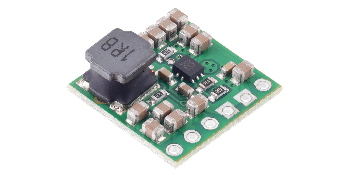
Boost converters generate a regulated output voltage that is higher than the input voltage.
Looking at these now, they seem to fit more of the requirements
worldly schooner
Yeah, polulu tends to serve the robotics community more, so a lot of their power products deliver much higher voltages and currents.
pulsar plover

Kickstart Design - Product Design
The AmpRipper 3000 is a next-gen power supply for portable / rechargeable projects! With Narrow VDC PowerPath Management and a 3A output current, you’ll be able to power high-current projects and fast charge a battery with a single module. A true plug and play battery charger module, compatible with
This is exactly what I need but is out of stock everywhere it looks like

Kickstart Design - Product Design
AR4000 now features a 4A output, I2C communication, increased efficiency, greater input voltage range, adjustable charge rate, and more options for user control. The AmpRipper 4000 Li-ion battery charger & boost module offers enhanced functionality, communication, and control options over its pr
This one is in stock 👀 I think I finally found a valid option.
pulsar plover

I think I got it figured if anyone wants to here about my solution feel free to reach out. Basically just maxamps for the 3.7 v 2000mah battery that’s being charged by the amp ripper, and being stepped up by the pololu to go into cm4
worldly schooner
pulsar plover
I think I got it figured if anyone wants to here about my solution feel free to ...
2000mAh? Isn’t that battery a bit small to be charging with that amp ripper? Generally you shouldn’t exceed 1C charging a lipo that isn’t specifically designed for high charge currents.
It’s also really tiny for a pi4.
Ignoring conversion losses, that’s still only around 30 mins of battery life at full load
pulsar plover
worldly schooner
2000mAh? Isn’t that battery a bit small to be charging with that amp ripper? Gen...
It charges up to 10A, and charging speed is adjustable
pulsar plover
worldly schooner
Ignoring conversion losses, that’s still only around 30 mins of battery life at ...
At the 5v 1a I was running it should last about an hr and a half
worldly schooner
Oh, right. At 5v 1A even the power boost 1000c would’ve worked.
pulsar plover
worldly schooner
Oh, right. At 5v 1A even the power boost 1000c would’ve worked.
There could be peaks, I’d rather not hit power limitations if possible
This system seems a better overall fit
amber raven
alright guys
so, a peer of mine have tested my electronic dc load that uses a mosfet and he can confirm that my electronic circuit can pull the expected amps, just not with the characteristics that i have hoped for
which is a linear transition instead of a discrete transition
this confirms that my circuit works, the only problem lies in the mosfet that im using, which is an IRFB4227PBF
it is a switching logic level mosfet which a lot of youtube tutorials say that it could work
but i guess using a switching mosfet warrants this effect
so, question is
do i need to change my mosfet into linear ones to get the desired linear effect that i wanted?
i'd buy those instantly if only one mosfet would cost like a cent instead of 5-10 dollars for the cheapest ones
knotty tiger
it might work with more feedback loops, as long as you don’t need them to change too quickly
 knotty tiger
no, like an inner loop to drive the gates to achieve a Vds
amber raven
uhm
are there examples?
my peer also said that i need a driver for these mosfets

something like this
knotty tiger
also why are all your 2 ohm resistors in parallel across both MOSFETs? that won’t work to balance their currents that way
amber raven
knotty tiger
also why are all your 2 ohm resistors in parallel across both MOSFETs? that won’...
oh those are just current limiting resistors
im using the design i got from here
but extended to 2 mosfets to share the load
coarse lark
the capacitors on my board are heating up

its one of these} 3

i think the middle one is either faulty or shorted
Ive reflowed them and replaced the middle one with my ghetto hot plate
coarse lark
ive solved the heating issue but its till too unstable for my taste, disconnects and reconnects constantly, ill be building a second unit once my soldering paste arrives
latent jungle
MLCCs (surface mount ceramics) are sensitive to thermal cracking. I know a lot of people think you can just crank a hot plate up to max and wait for the solder to reflow. That's a good way to crack MLCCs. You should give the board at least 2 minutes around 150C for everything to pre-heat before going for the reflow peak.
Also, when you have MLCCs anchored to a large ground plane, they can crack if you cool them down to quickly. (Super common mistake I see are people with toaster reflow ovens that pop the door open RIGHT after reflow. )
coarse lark
latent jungle
MLCCs (surface mount ceramics) are sensitive to thermal cracking. I know a lot o...
ah
that makes sense
i probably fried it with my soldering iron
fortunately my crappy ghetto hot plate heats up and cools down slowly so if i use that (when my solder paste arrives) there shouldnt be any problem
coarse lark
i was wondering why the S3 warmed up

thats the temperature they operate at... i think
 waxen halo
(Never quite sure if some questions belong in -projects instead of here.)
If I'm looking for short range (<6") wireless communication between two things, do not need high speed (couple bytes a second at most) and want to optimize for low power on at least one side, which tech should I be looking at? Wi-Fi? BLE? RFM69? NFC? One half will already have an ESP32, so I'm tempted to just have them both on the wifi.
coarse lark
waxen halo
(Never quite sure if some questions belong in -projects instead of here.)
If I'm...
Not sure if it fits your needs but have you tried ESP-NOW?
its communication between 2 ESP chips and ive gotten over 100m range with stock antennas
waxen halo
I have not, quick search seems interesting; I'll have a look and add it to the consideration list, thanks.
inland jungle
do you have direct line of sight for something like IR transmit/receive?
waxen halo
inland jungle
do you have direct line of sight for something like IR transmit/receive?
One portion will be moving, so IR would only be suitable for a wake signal maybe, past that it won't maintain LOS.
unique patio
waxen halo
(Never quite sure if some questions belong in -projects instead of here.)
If I'm...
BLE is named Bluetooth Low Energy because, well, it is. Apple AirTags and similar devices are BLE, and they can last a year or more on a single coin cell. And you can vary the output power on BLE. You can use BLE advertising to transmit data. \Nordic nRF chips are designed for potentially very low power operation
waxen halo
That's impressively low energy, well beyond my needs. Just needs to be low enough that wireless power can charge an internal battery and power whatever listening radio for the wake sequence. I think for the moment it makes sense to just plan on having an esp32 in the second piece as well and then I can pick one of those three options later.
unique patio
This is an interesting overview of binary number formats for AI model calculations: https://www.semianalysis.com/p/neural-network-quantization-and-number

Inference & Training - Next Gen Hardware for Nvidia, AMD, Intel, Google, Microsoft, Meta, Arm, Qualcomm, MatX and Lemurian Labs
 elder peak
This looks handy: https://www.keyelco.com/category.cfm/Screw-Terminals-Terminal-Blocks/Screw-Terminals-Slim-Line/p/476/id/447
Slim-Line PC Screw Terminals from Keystone Electronics
supple pollen
Keystone is an interesting company. I needed some parts for something that had been built in the 1980s. Keystone still offers the same parts. They have an extensive line of simple, useful things. I just bought some battery contacts there to build some custom battery holders. A few cents apiece, just made of bent wire, but very useful.
 onyx kernel
Is it possible to have traces in a Footprint without the DRC going crazy in EasyEda? or should traces in footprints be avoided?
 waxen halo
onyx kernel
Is it possible to have traces in a Footprint without the DRC going crazy in Easy...
waxen halo
onyx kernel
Is it possible to have traces in a Footprint without the DRC going crazy in Easy...
Is the net of the trace set to the same net as the pad?
onyx kernel
thats the thing i cant set a net name in the footprint editor
onyx kernel
Well its not relevant anymore cause i realized i need to separate those pads in to 5V and 3.3V anyways.
 fleet valley
Hiya folks. I'm currently looking for a way to turn an electromagnet on and off repeteadly in quick succession. Would a relay be the best way to go about it, or is there a simpler, better way to do it?
the electro I'm working with is a seed grove. Not sure if I could get away with just pulsing the signal from the mcu directly.
Another way I could go about it could be a small motor with a 3d printed holder and some magnets spinning. It's to trigger a pedaling sensor.
inland jungle
How fast, how much current?
inland jungle
And voltage?
fleet valley
Either 3.3 or 5 would work
inland jungle
Use a logic level mosfet or transistor and you should be able to switch it right from the mcu
fleet valley
Ah, got myself a whole box of npn and pnp's I can probably use for this then. Reckon a Pico will be able to handle 5v output intermittent or safer to go with 3.3?
inland jungle
Check the current rating on the transistors
fleet valley
Ait will do. Thanks a lot! Just wasn't sure where to start but with this info I have plenty to go on. Thank you very much Kevin, really appreciate it!
inland jungle
You'll be using 3.3v out so use a current limiting resistor to stay under the pin i/o current limit
fleet valley
I'm looking at Adafruit's Mosfet Driver
inland jungle
Yeah mosfet are a better choice for this typically
fleet valley
Can drive both motors and solenoids so could be used for both the electromagnet or the motor
I'll probably go for that then. Thanks so much!
This should wortk fine?

Ah yeah, max 1.5A, and I'm at less than half an A
onyx kernel
Hey. I'm wondering why the mcp23s17 has 3 address pins, when its communicating via SPI. I thought in SPI you use the CS pins to define who you want to talk to.
supple pollen
Those pins let you configure what address it listens for on I2C
Oh right, you said SPI
§3.3.2 of the data sheet ("Addressing SPI devices") mentions it, but I find the verbiage confusing
onyx kernel
i think ill just...
 unique patio
fleet valley
Ait will do. Thanks a lot! Just wasn't sure where to start but with this info I ...
unique patio
fleet valley
Ait will do. Thanks a lot! Just wasn't sure where to start but with this info I ...
you will need a kickback-protection (aka "flyback" or "snubber" or "snubbing" diode across the solenoid. We have a breakout with one included: https://learn.adafruit.com/adafruit-mosfet-driver https://www.adafruit.com/product/5648
fleet valley
unique patio
you will need a kickback-protection (aka "flyback" or "snubber" or "snubbing" di...
Aye that's the exact one I ordered 🙂
unique patio
ok, then you're all set!
fleet valley
Yis. Just waiting on parts and time to circuitpython it up
inland jungle
Yeah, was just coming here to mention the snubber 😄
 snow elbow
anyone have experience connecting the itsy bitsy lipoly backpack to an arduino nano?
i know they are meant for itsy bitsy boards but I saw some stuff online about people getting it to work, just nothing that concrete

Reddit
Explore this post and more from the arduino community
i tried this setup with an arduino nano every, except it doesnt have the vbus jumper, and i couldnt get it to work
restive gorge
onyx kernel
Hey. I'm wondering why the mcp23s17 has 3 address pins, when its communicating v...
Might it let multiple mcp23s17 devices share the lines, without needing to use up another CS pin? (https://ww1.microchip.com/downloads/en/Appnotes/01043a.pdf has a short note on this it seems.)
cursive sentinel
I believe that is the case, yes. IIRC the 23S17 still needs an I2C-style device address byte at the beginning of each transaction.
restive gorge
(Just for fun) I've recently been thinking using gpio pins connected to simple discrete logic chips as a programmable switch, in that one monitors changes from a set of pins connected to outputs of these devices, and "transfers" the logic levels to other pins connected to the inputs. (The connections being programatically defined.) Assuming for fun that speed is a non-issue, and there aren't any bi-directional connections to worry about:
- what "this doesn't make sense" do you see?
- I've been using keypad.Keys to monitor inputs just for a couple of hello-world tests - any alternatives in CP that come to mind for monitoring changes to pin levels? (haven't run into a need for this yet, but haven't sorted out how to monitor high-z inputs.)
supple pollen
You could always use a low level language or Arduino, to get more fine grained control of the pins and timing. Setting a pin to input makes it high-Z and easy to monitor its state (since it's an input)
 fresh fiber
I figure this is the best channel...
I'll start with, I'm a software guy, not a hardware guy...
I want to design a FeatherWing that allows me to connect 4 different NeoPixel boards. It's for a project that I want to keep simple for assembly and so good with somr soldering but don't want anything crazy.
Any guidance would be appreciated.
 torpid trout
supple pollen
You could always use a low level language or Arduino, to get more fine grained c...
torpid trout
supple pollen
You could always use a low level language or Arduino, to get more fine grained c...
Ack. Didn't realize it was easy to get an interrupt on a change from an external device going into high-z, when connected to a gpio input - everything seems to depend on essentially testing against a weak pull-up/down. Will explore
unique patio
restive gorge
(Just for fun) I've recently been thinking using gpio pins connected to simple ...
countio does edge detection. You can also set the pull to None on keypad to make it high-Z
unique patio
fresh fiber
I figure this is the best channel...
I'll start with, I'm a software guy, not a...
4 different NeoPixel boards
which boards are you talking about here?
fresh fiber
unique patio
> 4 different NeoPixel boards
which boards are you talking about here?
Small ones, like the NeoPixel Stick - 8 x 5050 RGBW LEDs
unique patio
fresh fiber
Small ones, like the `NeoPixel Stick - 8 x 5050 RGBW LEDs`
The RP2040 Scorpio has 8 NeoPixel channels built-in. The NeoPXL8 FeatherWing (two versions) can drive 8 strands as well: https://learn.adafruit.com/adafruit-neopxl8-featherwing-and-library/
you can also tie your four boards in series. If they are short, you may not see any difference visually if you update them all at once versus updating four different channels
one will be pixels[0:5], one will be [6:20], etc.
THe NeoPXL8 boards have a specialized library, but you could also just use them as level-shifters (which is all you need for simple reliable NeoPixel work)
fresh fiber
Those both only provide the data pin though yes? It's small enough that I haven't had issues running them if the power from the feather (total LEDs : 30)
unique patio
fresh fiber
Those both only provide the data pin though yes? It's small enough that I haven'...
not sure what you mean. The Scorpio provides 5 level-shifted GPIO outputs suitable for NeoPixel data lines. The NeoPXL8 also is 8 level-shifters, plus a +5V supply, plus some connectors
worldly schooner
fresh fiber
I figure this is the best channel...
I'll start with, I'm a software guy, not a...
Are you focused more on the Neopixel circuitry, or the physical connectors?
All Neopixels have the same 3 pins, but most of the boards don't really have any sort of connectors.
fresh fiber
So my goal is something easy to connect that provides both data and power. Like the NeoTrellis. Something like the NeoPXL8 or the NeoDriver are great, but then I need to deal with power separately...
 twilit mango
Hey, folks! I have an issue that feels hardware-related, but I'm guessing based on available info. I have multiple setups here of 60 LEDs wired to a level shifter FeatherWing (I'm using the NeoPXL8 as a level shifter, basically), and to an ESP32-S3 Reverse TFT Feather. The Feather is powered from a 10A power supply, through the LEDs, via the USB pin. I have one that is an ESP32-S2 Reverse TFT Feather. I noticed that one of my setups, the LEDs were flickering ever so slightly. So I tried a bunch of things, swapped power supplies and microcontrollers, and figured out that if I plug the Feather into USB power, the flickering stops. Further, I realised that the ESP32-S2 setup was not flickering, so I tried it on a different set of LEDs, and the set with the S2 is not flickering, regardless of which set I attach it to. This leads me to believe that for some reason, the ESP32-S3 only is causing flickering in the LEDs when not attached to USB power. And I am confused. Is there something weird about the USB pin on the ESP32-S3 Feather? (Please tag me or reply. Thanks!)
twilit mango
So, update. The charge LED on the ESP32-S3 boards, without USB power plugged in, flicker inconsistently (which is to say, usually it's a constant quick flicker without a battery, and on this setup without a battery or USB power, it's inconsistent). And, it turns out, the LED strips are flickering at the exact same inconsistent rate as the charge LED. I went back to the ESP32-S2 I'm using, and the charge LED is off. I checked to see that a battery worked, and it does, but regardless of the presence of USB power on the S2, the charge LED remains off. I verified with a second S2 that the charge LED should be working; it should be. Presumably there is something wrong with the charging circuitry on the ESP32-S2 I'm using, which would explain the lack of the charge LED, and also, potentially the lack of the flickering LED strips.
Further, the charge LED flickers consistently while the S3 is powered through the LED strips via the USB pin, UNTIL the LED strips light up. That is to say, the board goes through connecting to WiFi and AIO, which gives it time to be on before the strips light up. Once the strips light up, the charge LED is no longer consistently flashing.
So, there's something up with the charging circuitry that is causing the LED strips to flicker at the same inconsistent rate as the charge LED. Which... ok, wat?
So, as it was the easiest thing to remove in that circuit, I removed the charge LED, and the LED strips still flickered without it connected. (It was unlikely to be the problem, but still seemed worth checking.)
This is now a guinea pig board, and the next step we're going to try is to remove the charging chip.
twilit mango
That did not resolve the issue.
twilit mango
So, uff. I added a 1000uF electrolytic capacitor to the power lines, and the flickering issue on both the charge LED and the LED strips is resolved.
I have never in 7 years of messing with LEDs needed to add a capacitor into the mix, even though it's suggested.
Thanks for reading along! Hopefully this helps someone in the future. 🤦🏻♀️ 😂
distant raven
twilit mango
So, uff. I added a 1000uF electrolytic capacitor to the power lines, and the fli...
Crazy how that 1000uF cap can solve so many problems 😵
I was trying to emulate your issue at home but I didn’t have enough LEDs 😬
twilit mango
distant raven
I was trying to emulate your issue at home but I didn’t have enough LEDs 😬
❤️ Thank you!
I'm terribly unfamiliar with caps and what they can do. This was my housemate's idea, at which point I remembered one of the major LED guides having a photo with a capacitor jammed into the screw terminal, and realised that was a suggested thing.
I was correct on that recollection. 😄
Also, I'm now seeing that one of the other S3 LED setups is not flickering. I'm still adding the cap, but ugh. So inconsistent!
distant raven
Hardware definitely keeps us on our toes 😅
twilit mango
@distant raven Quick question, The voltage rating on a capacitor, is that a direct value associated with the voltage of the power supply? Or are there some shenanigans in it. e.g. I have 16V capacitors, on a 5V power supply, is that more than good enough.
distant raven
Yeah, basically the voltage rating is what the capacitor is rated to receive at a maximum. When picking capacitors, it’s a good practice to pick ones rated for at least 2x your anticipated voltage supply
twilit mango
Ah ok, got it.
distant raven
So 3.3V systems, 6V and above is perfect, 5V go 10V and above
distant raven
Yup 😊
16V is a safe bet when working with LEDs too because you will see somewhat of a voltage spike when the LEDs come on and draw a lot of current
twilit mango
I initially argued because I was thinking watts, which is obviously a whole different story, but after I repeated "volts" about 8 times, it registered properly in my brain what I was actually referring to,
Oh!
distant raven
It’ll dip a little while the capacitor starts supplying current and the main supply comes back up. Kind of a ripple.
twilit mango
I had an issue on the frankenboard where the first time I powered it up after removing the charging chip, it went into safe mode with a "power dip" as the reason. Reset fixed that. Then, the first time after adding the cap, same issue. Reset fixed that too.
Yes!
Ok
That's good to know. I thought we might have broken the board. 😄
Brian (housemate) was not so convinced that we broke it. This explains why.
It has not power dipped to the point of safe mode since then.
distant raven
If you have that massive capacitor on the 5V supply and no LEDs attached, you’ll experience a similar restart
twilit mango
Interesting
distant raven
On one board I have, I didn’t have an LED strip attached and it would power up and then restart as the capacitor took a bit to being the 5V rail back up to 5V
twilit mango
Because the cap is charging up? Or whatever the term is...
distant raven
Yeah, basically
twilit mango
Noted
distant raven
If you have a breadboard, you can use a multimeter and a stop watch to time difference RC circuits to see the voltage build up. It’s a pretty common lab in intro circuits courses
Also a fun time to blow up caps
twilit mango
distant raven
I was trying to emulate your issue at home but I didn’t have enough LEDs 😬
Also, it occurred to me just now, the idea of not having 60 LEDs in this house is hilariously unfathomable. I have an embarrassingly high number of LEDs. 😄 🤷🏻♀️
distant raven
The last strip of LEDs I had I chopped up lol
twilit mango
distant raven
If you have a breadboard, you can use a multimeter and a stop watch to time diff...
See, these are fundamentals I'm missing. Because of my path to get how I got here. There are a lot of holes in my knowledge. 🙂
distant raven
 twilit mango
I'm missing some Python fundamentals as well, but my electronics fundamentals are abysmal.
twilit mango
distant raven
Woah!
distant raven
I have parts to make another one, but I need to reorder the controller as it is supposed to become my grow light host
twilit mango
Ah ha! Nice!
I was going to ask what the why was. But you beat me to it.
That's what all of these are. Grow light setups. 🙂
distant raven
I need to replace the ESP32-S2 as they don’t really make the Wrover modules anymore
twilit mango
I have an air plant problem. 😅
distant raven
I have a gardening problem 😬
twilit mango
distant raven
I need to replace the ESP32-S2 as they don’t really make the Wrover modules anym...
Aren't the S3s kind of drop in replacements?
distant raven
There’s no Wrover S3 modules 🥲
distant raven
Just Wroom or whatever they’re called and the mini
twilit mango
Yeah wroom is the other one
distant raven
I like the mini modules though, great space savers
twilit mango
Indeed
distant raven
I use the s3 with ufl connector for my KeyBoy boards
 twilit mango
I'm using S* Feathers with TFTs on them.
twilit mango
distant raven
I use the s3 with ufl connector for my KeyBoy boards
Ooooh. What do those connect to?
distant raven
It’s like a little gameboy
 distant raven
 distant raven
Case design needs some work, and I need to order the next iteration of the PCB shown above. Some minor hw fixes
Yeah, a previous version with a select button for menus
twilit mango
Ah


 distant raven
A little touch piano for learning about generating sounds and stuff
And of course stemma qt for more sensors, or a display, or whatever else you can think of 😊
twilit mango
My very first project ever was a light up touch tone piano using Circuit Playground Express, and key limes. I have a special place in my heart for touch pianos. 😊
twilit mango
distant raven
And of course stemma qt for more sensors, or a display, or whatever else you can...
Always a good thing.
distant raven
I’m working hard to make products that are focused on learning concepts rather than being overly broad in application
twilit mango
Love it, love everything about it.
I also have a special place in my heart for learning and teaching. 😄
distant raven
I’m finally finding my footing again with designing and making. Things were rough for a couple months there. And making teachable things is where I found my passion again
twilit mango
I mean, brain, really. My heart wouldn't be working all that well with a bunch of other stuff in it.
twilit mango
distant raven
I’m finally finding my footing again with designing and making. Things were roug...
This is great to hear! I'm really happy you found your passion.
distant raven
Same, I was really lost feeling for a while
twilit mango
I know the feeling. Finding a path after that is indescribably amazing.
distant raven
Yeah, I’ve got a ton of ideas rattling around now and I’m excited
twilit mango
Excellent.
 tough matrix
Hi, @twilit mango
nice seeing you again - haven't seen you in this discord for a while!
(not that I am here that frequently either)
hushed smelt
Thought my well pump was finally fixed and sprinklers working this week. Then it kept shorting again. I've had 2 electricians and a sprinkler specialist try to figure out the problem. The sprinkler guy said he ran new wiring to the pump but I found some evidence that suggests he just wrapped the conduit with electrical tape to try to water proof it and called it a day.
So I decided to unwrap the electrical tape and have a look for myself. Do you think these are new wires?

You can only see the ends where they go into the pump. Only the ends are visible so I suspect he cleaned the ends with a wire brush and called it good. If he would have removed the wires it would have been plain as day where the short is coming from. So in the end I had to do it myself.
This rant brought to you by Carls Jr.
Thought the people here might appreciate the That's 240V DC btw.
fleet valley
Hiya folks. Does anyone know what kind of signal this magnetic pedal assist sensor sends to the ESC, and whether it can be emulated with an MCU at all?
 hushed smelt
If it's magnetic then it's likely just a switch. There are many ways to use AT switches with microcontrollers. Check out this excellent guide by Chris Young. https://learn.adafruit.com/building-the-assistive-technology-ultimate-remote/assembly-instructions
fleet valley
hushed smelt
If it's magnetic then it's likely just a switch. There are many ways to use AT ...
I checked the voltage output of the signal wire when I wiggled a magnet in front of it and it fluctuated. Would a switch type signal do that?
It’s a cadence sensor so I assume it measures the speed at which a magnet passes by it and frequency
Been trying to find detailed info on how it works but can’t find anything remotely similar to a diagram or anything
hushed smelt
If it's producing its own voltage then probably hall effect. https://www.adafruit.com/product/158
fleet valley
Yeah it is
Realistically all I need is to know what kind of voltage/signal it sends back so I can feed it to the ESC from an mcu
hushed smelt
You can setup a microcontroller to read the analog voltage as the switch. All you'd need to do is put some ferrous metal under it like iron and that will trigger it.
fleet valley
The idea is to fully bypass the hall effect sensor, and manually send the trigger signal from an rp2040 to the esc’s input
But I think it’s just a matter of pulling down on it.
hushed smelt
Ah then that depends on what kind of signal the ESC wants/expects.
fleet valley
Yeah that’s what I’m trying to figure out but I don’t have a logic analyzer
hushed smelt
Some are 5V some are 12V. I imagine if it's an AT device it's not going to be high voltage.
fleet valley
This one is 5
Has vcc, gnd, and signal
So I can use vcc and gnd to power the rp2040 and use a pin in the board to send the signal
hushed smelt
Well the RP2040 signal voltage is only 3.3v so you'll need a logic level shifter from 3.3V to 5V.
This will do https://www.adafruit.com/product/5649
fleet valley
I can work with that. I’m just unsure how to/what signal to send
hushed smelt
Well if it's an ESC then it might need a PWM signal which the RP2040 + the level shifter can do.
fleet valley
I’ll read up on how to work with PWM signals. Btw, can a PWM signal be regulated with a potentiometer if using circuitpython?
I am very low level when it comes to logic level stuff
hushed smelt
good question, i don't know, someone else will have to jump in.
fleet valley
No probs. Thanks a lot for all the input!
fleet valley
Checking the signal voltage, I'm seeing it's outputting in the millivolts, never going over 100 mV. Would I still need to step up the 3.3v to 5v to get this working?
 civic cairn
fleet valley
I’ll read up on how to work with PWM signals. Btw, can a PWM signal be regulated...
civic cairn
fleet valley
I’ll read up on how to work with PWM signals. Btw, can a PWM signal be regulated...
I personally prefer C for this. But, circuitpython would also be able to do this since effectively you are only changing the frequency and amplitude of a square wave.
fleet valley
My programming skills are super limited, take me outside of Circuitpython using docs or .yaml and I'm lost
civic cairn
fleet valley
Checking the signal voltage, I'm seeing it's outputting in the millivolts, never...
Usually Hall effect sensors are interfaced with the help of an Op-Amp to get stable voltage reference outputs. That way, it will work more or less as a potentiometer providing a reference voltage betwwen 0-5V.
Detecting mV may be a bit tough. But that is how I would approach this
fleet valley
So this is the output I have from reading the signal:

And checking with the multimeter the readings were in the mVs
twilit mango
tough matrix
Hi, <@330227457296957440>
nice seeing you again - haven't seen you in this disc...
Hey! 😊
civic cairn
fleet valley
So this is the output I have from reading the signal:
Interesting. If possible, can you take a reading while moving a magnet near the sensor. Or is that reading taken when the magnet is near the sensor?
fleet valley
It is while moving the magnet
So 40% duty cycle every fo 20ms at a time seems to be the signal needed to get the motor to engage
Or what the ESC expects
civic cairn
So it is a flat line when no magnet is detected I suppose
fleet valley
correct
civic cairn
Based on my calculations, it is a 50Hz square wave. Does it make sense
fleet valley
Ah, since the baseline is flat, and it's only pulling high, it'd be 50%?
civic cairn
Should be.
fleet valley
Would you recommend having a resistor or some other kind of protection between the board and the signal receiver?
civic cairn
fleet valley
Would you recommend having a resistor or some other kind of protection between t...
What I would do would be a resistor divider with the output going through a 1K resistor to actually take the readings.
The frequency is not that high and Voltage doesn't seem to be either. But the divider through the resistor will act as a safe side
Also, does the frequency of the square wave change with how fast the magnet near the sensor moves?
fleet valley
I saw it move about, however I think that might've been my magnet swaying being irregular
Can't take live readings so had to record snapshots
(Not sure if you can do live readings on PulseView)
civic cairn
fleet valley
I saw it move about, however I think that might've been my magnet swaying being ...
That does not matter. I am only trying to determine whether it is the direct output of the hall effect sensor or whether it is going through some sort of circuitry
fleet valley
Ah gotcha
civic cairn
If it is swaying, it means that its the hall effect sensor connected directly.
fleet valley
Bear with me, let me get all the setup back up and run some readings. Will ping you.
civic cairn
fleet valley
Bear with me, let me get all the setup back up and run some readings. Will ping ...
Sure.
fleet valley
@civic cairn This is with no magnet at all and Polarity = Active Low

sorry took the reading too fast

And this is moving the magnet
 civic cairn
It seems to be a conventional Hall Effect sensor.
So, what I would do would be to try 2 conditions
fleet valley
2 conditions?
civic cairn
If you have the ESC handy, trying out a conventional PWM generator code which will vary the frequency. Put the output across a 10K resistor which will be connected to the ESC. If the ESC is not explicitly checking RPM, It should work
fleet valley
ooh gotcha, and see how the motor reacts
civic cairn
However, if the ESC is smart, it will need the frequency to match to engage the motor so that it does not accidentally enable the motor while you are just pushing the behicle
vehicle*
civic cairn
fleet valley
ooh gotcha, and see how the motor reacts
Yeah
fleet valley
Thanks. Don't have it handy atm but will keep that in mind for the project. And with this test and everything you've told me I now have a pretty good idea on how to run tests and figure this out. Thank you so much Atul!
civic cairn
fleet valley
Thanks. Don't have it handy atm but will keep that in mind for the project. And ...
Hopefully my understanding of the board is not wrong and that your project works when you try it out. All the best. Gald to have helped in some way.
 stark arch
Hello, I was looking to get some advice on a sensor I was looking to use for a PCB. For some background, I want to include an inertial measurement unit on my board, prefferably one with an established library so I don't have to make it myself. After looking around, I settled on the BNO055. I am planning on basing my schematic off of the adafruit breakout board so I can use the adafruit libraries. The first issue I ran into was picking a crystal osscilator to fit the specifications; the only specification they give is the frequency, 32.786 kHz. Because nothing else is given, should I worry about load capacitance, ESR, or drive level? Also, it mentions that the external clock must be selected by setting a bit to a specific value. I assume this can be done by just writing to that specific bit, similarly to: https://forums.adafruit.com/viewtopic.php?t=189788
I apoligize for the long question
Schematic & and link to breakout board: https://learn.adafruit.com/adafruit-bno055-absolute-orientation-sensor/overview


Adafruit Learning System
Absolute orientation without the Ph.D in digital signal processing!
distant raven
stark arch
Hello, I was looking to get some advice on a sensor I was looking to use for a P...
Here’s what the data sheet recommends

ESR doesn’t seem to be an issue here. You could probably pick the cheapest 32.768kHz oscillator that needs 22pF load capacitors and be fine.
Your other question can also be answered with the data sheet: https://www.bosch-sensortec.com/media/boschsensortec/downloads/datasheets/bst-bno055-ds000.pdf
stark arch
Alright, thank you. Using Cl=Cc*.5+Cstray, and assuming stray is 5pf, this would make the load capacitance 16pf. However there don’t seem to be any available at that frequency and capacitance. 18 (with a 100 uW drive level, which I assume is adequate) is the next closest option, and this would make the capacitance values 26pf. Should I still use the 22pf capacitors in this case or opt to place them with the 26s?
distant raven
stark arch
Alright, thank you. Using Cl=Cc*.5+Cstray, and assuming stray is 5pf, this would...
I’d assume small stray capacitance, between 1-3pF is fairly common
stark arch
Ok, so then a 12pf crystal would make sense. I assume drive level isn’t something I should worry about in this case-correct?
distant raven

Digi-Key Electronics
Order today, ships today. ECS-.327-12.5-16-TR – 32.768 kHz ±20ppm Crystal 12.5pF 90 kOhms 2-SMD, No Lead from ECS Inc.. Pricing and Availability on millions of electronic components from Digi-Key Electronics.
This would get you pretty close
stark arch
Thank you
 ionic vault
Hello, I need help to find out what this is.
I was cleaning my mouse and I broke a piece that looks like this one and now it wont charge. It has 3 pins and it has AO7 2/3 written on top.
 distant raven
ionic vault
Hello, I need help to find out what this is.
I was cleaning my mouse and I broke...
distant raven
ionic vault
Hello, I need help to find out what this is.
I was cleaning my mouse and I broke...
It could be a handful of things, though it is most likely a mosfet.
Depending on what’s around it, it could be a supervisor IC, mosfet, voltage regulator, line buffer, etc..
Q is often used to denote mosfets so that would be my first guess
ionic vault
distant raven
It could be a handful of things, though it is most likely a mosfet.
Okay thank you!
inland jungle
anyone ever use the JLPCB layout service? Do they do a good/thoughtful job based on circuit requirements, or just place components wherever?
stark arch
I selected this crystal to use on my circuit (https://www.mouser.com/datasheet/2/122/ECX_1637BQ-1919097.pdf), however it has 4 pins. Don't crystals normally only have two?
distant raven
stark arch
I selected this crystal to use on my circuit (https://www.mouser.com/datasheet/2...
Nah, they can have 2 or 4
Some even have 3
stark arch
So when I connect the crystal up to the load capacitors (like the image attatched for the two pin one) would I just attatche one in/out and one gnd to both the bottom and top trace?
 distant raven
If it has two pins, you just connect them to the XIN/XOUT pins of the device and to one end of the load capacitors on each side.
stark arch
Sorry, I meant if you were using the four pin capacitor in the place of the two pin
supple pollen
stark arch
So when I connect the crystal up to the load capacitors (like the image attatche...
No, connect one in/out to each trace, and connect the grounds to ground
stark arch
I am using an sd card with the attatched pin diagram. On the schematic I am basing my board off of, the diagram it uses only connects one pin to gnd. In this case, do I only need to connect one pin to gnd or should I connect all 5 to gnd?


(left is pin diagram, right is schematic)
and this is what the sd card I am planning on using looks like in a schematic
 supple pollen
Shielding is best if you connect all of 'em, but technically you don't have to.
stark arch
supple pollen
No, connect one in/out to each trace, and connect the grounds to ground
like this?
 stark arch
supple pollen
Shielding is best if you connect all of 'em, but technically you don't have to.
stark arch
supple pollen
Shielding is best if you connect all of 'em, but technically you don't have to.
👍 thank you
supple pollen
Yeah, that looks right to me
 native plover
I have a controller PCB for a dental piezoelectric scale remover that isn't working properly (looks like it's working, but doesn't achieve anything - my guess: correct frequency, but insufficient amplitude). Replacing the PCB solves the issue, so the fault must be on there, but nothing looks obviously broken. Any thoughts on what might have failed? I'm hoping to replace an individual component next time, instead of the whole PCB. X98 is the connector that connects to the unit and handpiece. Technician said there's some sort of power adjustment going on based on handpiece temperature, but I don't know if there's electronic feedback for that or if it's somehow self-regulating within the handpiece. The handpiece does not have any further electronics as far as I know, aside from the piezo crystal and a light.


 supple pollen
May be magnetostriction instead of piezo. The main difference is that usually magnetostriction is a low impedance drive signal, and piezoelectric is a high impedance drive signal. I'd look at the output driver circuitry and particularly the solder joints on it.
native plover
supple pollen
May be magnetostriction instead of piezo. The main difference is that usually m...
I thought this whole PCB was pretty much the driver 🙂
There are more electronics in the unit to control user input, speed (in this case amplitude) and such things.
This PCB is the one that specifically handles this one instrument
This is the part of the handpiece that generates the oscillation, guess the circled sandwich-looking structure is the piezo stuff. Not sure what's inside the copper-coloured cylinder behind it. The tubes are for cooling water and run through to the tip.
 stark arch
Another crystal question:
For my IMU, I needed a 32.768kHz crystal. I chose: https://ecsxtal.com/store/pdf/ecx-306.pdf. This was to be used for the crystal in the diagram attatched. However, after downloading the footprint and importing it into the schematic design softwarem there seems to be two extra pins. Do I only need to connect to pins 1 and 4 to connect to the crystal? There doesn't seem to be anything in the datasheet about it.

 distant raven
stark arch
Another crystal question:
For my IMU, I needed a 32.768kHz crystal. I chose: ht...
distant raven
stark arch
Another crystal question:
For my IMU, I needed a 32.768kHz crystal. I chose: ht...
Those get connected to ground
4 pin crystals have 2 pins for connecting to the crystal input/output of the host device and 2 that connect to ground.
stark arch
alright, thank you again
supple pollen
native plover
This is the part of the handpiece that generates the oscillation, guess the circ...
I suppose you could measure the resistance across the handpiece circuit. If it's low, it may be magnetostrictive. If it's high, it may be piezoelectric.
native plover
supple pollen
I suppose you could measure the resistance across the handpiece circuit. If it'...
Which hints would that give me as to what is actually broken? Visually, it all looks fine.
supple pollen
It'll give you an idea of likely circuit configuration. My guess is still a cracked solder joint.
stark arch
For my circuit, I have a single 7-12V source in which is fed directly to mosfets and a 5V regulator. This 5V is used to power servos and is also regulated to 3.3V to power a microcontroller and some sensors. Should I tie all of these grounds together on a single plane or isolate them based on voltage level?
stark arch
Also, for the 5V conversion, the servos will likelly draw up to 500 mA in addition to whatever the microcontroller draws. I am worried a normal voltage regulator will overheat as it won't be in an open enclosure with amazing air flow, however I am also worried that a buck converter will negatively affect the accuracy of the sensors. If I simply put the buck converter on the opposite side of the sensors and microcontroller on the PCB, will that solve any potential issues? Or should I just stick with the regulator?
tough matrix
what kind of sensors?
I wouldn't worry about interference from buck converter affecting the MCU and most sensors (such as IMU or sonars/laser ToF distance sensors).
And using a linear regulator to regulate down from 12v to 5V is very likely to lead to overheating, so I'd go with a buck converter.
Note also that typical "standrad size" servo can draw more than 1A per servo; even micro servos (e.g. MG90s) can draw up to 400 mA per servo when stalled.
stark arch
a barometric presssure sensor and a 9dof intertial measurement unit
should a single ground plane connect everything or should I isolate the ground for each voltage level
tough matrix
stark arch
a barometric presssure sensor and a 9dof intertial measurement unit
then this shoudl be fine.
BTW, what 9 DOF IMU are you using? I thought that no one makes 9 dof anymore, only 6 dof.
As for ground, generally all grounds should be tied together, regardless of voltage level
stark arch
BNO055
I don't think bosch is making it anymore though
it has good libraries and is powerful so I still picked it
inland jungle
Often analog ground planes are separate from noisy/digital planes and tied together at a single point
stark arch
alright, I should be good then because I believe both sensors are I2C
stark arch
Follow up on that buck converter-
I was looking at the LM22673 (5V 3A should be more than enough to power my mc and two 9g servos) and was attempting to follow their design procedure, but for some reason I keep calculating the value of L to be 82 uH, which doesn't seem to be right. I think something may be going wrong in my calculation. The second picture attatched depicts the equation they recommend using to calculate the value of L. As the max input voltage is 42V, the output voltage is 5V, the output current is 3A, and the frequency is 500kHz, I assumed it would be calculated as ((42-5) x 42)/(0.3 x 3 x 500 x 1000 x 42), but this gets it to be 82 uH, not 8.2. Am I missing something? It also says to use the maximum realistic value of voltage when calculating, but when I do that (using 12V) it still is off by a factor of two. Furthermore, I believe the typical application circuit was made assuming 42V to be the maximum value.


thank you in advance for all the help
tough matrix
The numerator is (V_in - V_out)*V_out, so it should be
((42-5) x 5)/(0.3 x 3 x 500 x 1000 x 42)
and not
((42-5) x 42)/(0.3 x 3 x 500 x 1000 x 42)
which gives you 9.8 uH - close enough to what they suggest. Using v_in = 12v gives 6.5uH.
And inductivity for DC-DC buck converter need not be very precise - for most purposes, decreasing it by a factor of 1.5 will not be that bad, it will just give you higher ripple, and increasing by factor of 1.5 will actually make the ripple lower at the price of making the inductor bulkier and more expensive.
stark arch
Ah I see- yeah that makes a lot more sense
stark arch
Ok, so I chose a buck converter and am now attempting to spec the parts for it, if someone could look over my work to see if I am in the right direction that would be awesome (keep in mind this is new to me). I chose a 5V 2.7A converter with the following datasheet: https://www.mouser.com/datasheet/2/609/MAX17644-3127689.pdf and a typical application schematic attached. I then calculated some basic values, which is in the picture of the google sheet attached. My calculated inductor value was close to 8.2 uH, so I was planning to do the same. As ceramic capacitors have a lower capacitance when a voltage is applied across them, I was planning on doubling the capacitance of all the capacitors except for C2 (because I don't have a specific soft start time in mind, so I don't think it will really matter). If this is right so far, my next obstacle is finding the right components to fit the specifications, which is what I have some questions with. 1. For the inductor, I assume I just find one with a low DC resistance, the right inductance, and a rated current of max current output * 1.3. For the resistor, I assume nearly any with the right resistance and a low tolerance will do. For the input capacitor, voltage should be above max input while the output should be above the max output. Both should have a X7R dielectric. I assume the dielectric does not matter for any of the other capacitors--should I still spec those to have a similar max voltage? Should I be concerned that the feedback network does not use resistors? Also, should I worry about isolating the different grounds used in their typical application (they use two different grounds, then unite them at a single point). If I should isolate grounds, which should I connect to the ground plane on my PCB?


(sorry for the paragraph-I tried to make it as detailed as possible)
supple pollen
The dielectric determines how much the capacitance drops when voltage is applied. The usual approach is to use a decent one, such as the X7R you mentioned, and choose capacitors with around twice the rated voltage as they voltage they'll actually be used with, so the capacitance change is small.
stark arch
Should I isolate the two grounds and connect them at a single point like they do in the schematic?
tough matrix
a possibly irrelevant question: do you plan to produce your board in quantity, or will it be a one (or two) unit only?
because in the latter case, it might be easier to just buy a preassembled buck converter such as e. g.
and attach it to your board.https://www.sparkfun.com/products/21256
(or, if you want a cheaper option, just search Amazon)

The SparkFun BabyBuck Regulator Breakout - 5V features the AP63357, a 3.5A synchronous buck converter with a wide input voltage range of 3.8V to 32V.
 unreal python
Hi! Is anyone familiar with JLC pcb fab? I sent a board in and for some reason the board preview shows these rectangular cutouts on the FPC

Looks like it only happens on unconnected pads
distant raven
Strange, I’ve not had that happen to me
stark arch
tough matrix
a possibly irrelevant question: do you plan to produce your board in quantity, o...
It would definitely be easier, and I am only makign one or so of the boards. However, I want the experience designing a full PCB and wanted to not use any breakout boards, which is why I am attempting to do it myself
With that being said, the board you sent has a schematic attached, so I think it could make more sense to just use that
The Board looks like it requires a voltage applied to the enable pin:
Would it make sense to just route vin to the enable pin (it can take up to 32V, and vIn will only be 7.4-9V max). Or would it make sense to remove the resistor between Vin and Enable and combine them for the second resistor?

my only concern is this converter seems to run very hot
supple pollen
Could be inductor saturation, inductor losses, capacitor losses, or excessive current draw
stark arch
^my guess would be excessive current draw-they say the converter is hot especially when drawing 1-2A
 grave nebula
Any chip suggested for 12 to 3v3 birectional levelshifter ?
supple pollen
What kind of signals?
grave nebula
TX RX and clock from a Nissan OBD2 Consult 2 signal
9600 baud at 153.6 Khz clock speed
I considered using a MAX232
But for some reason https://forum.arduino.cc/t/nissan-consult-and-arduino/232484/19 they used a combination opamp and transistors
Arduino Forum
Hello, Google users working on Nissan Consult and arduino, please drop a note of what you're doing and your results so far.
tough matrix
stark arch
The Board looks like it requires a voltage applied to the enable pin:
Would it ...
The two resistors are there to implement undervoltage lockout, i.e. disable the converter when V_in is too low, see page 15 in the datasheet here: https://docs.sparkfun.com/SparkFun_Buck_Regulator_AP63357DV-7/component_documentation/AP63356-AP63357.pdf
If you do not need that, you can just remove the resistors altogether and tie En to Vin
stark arch
tough matrix
The two resistors are there to implement undervoltage lockout, i.e. disable the ...
That makes sense. The reason I was questioning it was because on the datasheet for the SparkFun Regulator mentioned that EN must be pulled high for the regulator to turn on. I will be using a source well within the 6-32V input range, so I think I can just remove them
stark arch
Question about testing for continuity:
I have read a bunch on testing for continuity using arduinos. For my PCB, I am attempting to test if a pyro charge is connected--attached is the schematic I am using for the pyro channel. Theoretically, if I connected a voltage divider after the 1ohm resistor with a high resistance to 3.3V, then connected that to a pin on my uC (and would use analogRead() to determiite continuity), would that be an effective way of doing so? The second image shows what I was thinking. I would think I could read the value, and if it is high then it would be assumed to be continuous (keep in mind some of this is new to me).

 coarse lark
while making a new board i started to notice the copper filled areas no longer reach the edges of the board

is this something new from 8.0.1?
this didnt happen before
here is my last board

copper fill reaches the edge
knotty tiger
stark arch
Question about testing for continuity:
I have read a bunch on testing for conti...
for something like a pyro charge, i think i'd want to make sure the design can tolerate any single part failure without creating an unsafe condition. what's the firing current for the pyro? and what happens if the GPIO you're using to read the voltage is accidentally driven due to a code error or crash?
stark arch
knotty tiger
for something like a pyro charge, i think i'd want to make sure the design can t...
The firing current is around 2 amps (plus or minus some). The mosfet is rated for over 4 times what I need, so very overkill. If any current from the gpio pin made it to the charge, it would be much much lower than anything that could light the pyro (max is 10ma without any resistors). My concern is how I’m verifying whether the connection is continuous, which I am unfamiliar with which is why I asked if the way I did it made sense. I assume if I can calculate the voltage, I can use that to calculate the resistance and also determine if the pins are shorted
knotty tiger
stark arch
The firing current is around 2 amps (plus or minus some). The mosfet is rated fo...
yeah, that seems like a reasonable divider for testing continuity, depending on the ADC range on the chip. what’s the cold resistance of the charge? that might limit whether you can distinguish a short circuit
knotty tiger
stark arch
The firing current is around 2 amps (plus or minus some). The mosfet is rated fo...
7.4V supply, 2A firing current implies about 3.7 ohms hot resistance; cold will likely be lower, you’ll probably need smaller resistors in your divider to detect a short, and doing that while maintaining adequate safety margin might be tricky
stark arch
Sorry I wasn't clear- 2A is the minimum to light the charge
the actual resitance of the charge is much lower, so there will be more current going through the charge than necessary
The nominal resistance of something like an estes charge is something like .7 Ohms
And I am fine with not checking a short, was just something that was within the realm of possibility. So I think it may be better to just keep the higher resistance values and play it safe
stark arch
knotty tiger
yeah, that seems like a reasonable divider for testing continuity, depending on ...
range of the chip is 0-3.3V. At the max possible voltage going through the divider it should be around 3.2-3.1 V, so I should be within the range
 brittle silo
hi folks - tired of home etching so experimenting with pcb production from china for the first time. F360 is flagging errors on these 2 mounting holes being too close to the edge - will that prevent manufacture or is it more for my info?
 stark arch
Usually the manufacturer has specified tolerances you have to follow. For example, at JLCPCB (https://jlcpcb.com/capabilities/pcb-capabilities) they require 0.3mm between copper and the board edge
Printed Circuit Board manufacturing and assembly capabilities, PCB technologies or design rules for guide of PCB design and production
brittle silo
thanks, I'll try to fix it. can't really make the board bigger and still fit, so I guess I can shave some off those mounting hole copper surrounds
knotty tiger
stark arch
And I am fine with not checking a short, was just something that was within the ...
you might be able to detect a short while firing, but that’s presumably less useful to you
stark arch
yeah itll be closed for a maximum of .2-.3s so it won't really matter at that point
thank you though
grave nebula
grave nebula
But for some reason https://forum.arduino.cc/t/nissan-consult-and-arduino/232484...
Im thinking of making a couple of outputs to test
coarse lark
coarse lark
while making a new board i started to notice the copper filled areas no longer r...
Im not mad or anything, in fact i think it looks pretty good and its a good idea to have distance between the ground plane and edge, but i always get confused when something changes completely without me touching anything
Still, an option to set up the distance would be very nice
coarse lark
I jus wanna set the margin to 5 mils
tough matrix
brittle silo
thanks, I'll try to fix it. can't really make the board bigger and still fit, so...
It won't stop JLCPCB from manufacturing your board, but they dont' guarantee that th copper won't be slightly damaged when it gets close to the edge. If it were a trace that close to the edge, that might be a problem, but for a large through-hole, I think you should be safe.
 open marten
@plucky summit so i bought an FM radio i2c device (ScoutMakes FM Radio Board - STEMMA QT / Qwiic PID: 5651). the first bought it I got a stiff black wire for the antenna but the 2nd one I got a yellow lose wire for the antenna. is it possible to send me a new stiff black wire to me pleases? here's my order number "Order #3257830-0311859539"
I don't want the yellow wire i got with that order. i want the stiff one please?
supple pollen
The product page says the antenna isn't included, so that's probably a bonus anyway. You can make your own antenna out of any stiff wire, 770mm long.
distant raven
Also Adafruit doesn’t provide order support through discord, best to use the forums and support (at) adafruit (dot) com
stark arch
I have a concern about the 1 ohm resistor in this mosfet used to drive a pyro channel. I have seen others use a 1 ohm resistor to limit current, but with 7.4V over a 1ohm resistor the power dissipation required will be over 50 W, which will require larger resistors than I want. I can get smaller resistors with a dissapation up to 1.5W. If the circuit is closed for a very brief period of time (say .2s) will the smaller resistor work fine? Or should I just remove the resistor altogether? I assume if I use the smaller resistor, I also will need to connect the voltage divider before the resistor.
 knotty tiger
stark arch
I have a concern about the 1 ohm resistor in this mosfet used to drive a pyro ch...
knotty tiger
stark arch
I have a concern about the 1 ohm resistor in this mosfet used to drive a pyro ch...
what are you protecting by limiting the current? the MOSFET?
stark arch
I'd assume that's what's going on, though I don't think that's necessary as the mosfet is rated up to 40A and the nominal resistance on the pyro charge is .7ohm. With 8.4V max the current shouldn't reach anything near that. That's just what I've heard, so I wasn't sure. The only other idea I would have for why would be to know the current going through for calculating resistance
knotty tiger
what’s the 7.4V? some kind of battery? maybe its internal resistance is enough to limit your current
yeah, current sensing is one possibility, but you can probably go lower
knotty tiger
i mean, you’d probably need some kind of differential amplifier to get an accurate current reading, due to the on-state resistance of the MOSFET being possibly nonlinear. at that point, a smaller resistor could work
stark arch
Yeah I don't plan to accurately read current, so that'll be fine. If I use a lower resistor, won't that mean it would dissapate more power though? Or do you mean higher resistance
knotty tiger
power is I-squared-R, so generally lower sense resistance is better, as long as you get enough resolution for your needs
you presumably want most of the power going into your pyro
stark arch
Would keeping the 1 ohm resistor create any issues (as long as I make sure the voltage divider to check voltage is before the resistor)? I don't think power will on the charge will be a problem, so I am unsure whether a lower resistance will be necessary
my main concern was whether the power dissapated across the 1 ohm resistor would be too much to handle for a short period of time
knotty tiger
power ratings are generally given as continuous. if you’re very lucky, there will be a separate peak power rating, but i’m not sure even power resistors specify that
the peak power limit tends to be the melting or boiling point of some limiting internal structure, so you need some thermal modeling to get that
stark arch
Yeah, I've used 1ohm resistors with higher power ratings than their continous (with a similar setup) before and it's been fine. My prediction would be that they just get really warm for a brief period of time, then cool down. The loop will only be closed for .2s or less, so I personally don't think that'll be enough to fully melt the resistor
knotty tiger
yeah you’re going to have a fairly low duty cycle, so as long as the resistor has a large enough thermal mass, or good enough heat sinking, you can probably exceed the continuous rating by a lot (not going to give specifics, because i don’t have enough info)
stark arch
was planning on using 805 or 1206 resistors with a power rating of 1.5W, and place them further away from my buck converter which will hopefulyl be enough
some of them say that they've been tested with 400V
none really give a max power rating though, as you've said
brittle silo
tough matrix
It won't stop JLCPCB from manufacturing your board, but they dont' guarantee tha...
further, will these orphan holes on the rotary switch cause a manufacturing problem for the pcb?


not content with having them overlap the edge, I went and moved them into space 🙂
 subtle sundial
I'm working on my first circuit design for a project of mine. I'm trying to add the hardware needed to drive an e-paper screen onto a board with an ESP32 WROOM-based customized clock. Most of the basic stuff works fine-- the ESP32 is alive and well and it runs the WS2812 in the clock just fine. The issue I'm having with with the driver circuitry for the epaper screen that I'm mirroring from the waveshare universal driver design and the epaper chip's datasheet itself. Is this a good place for me to get help troubleshooting it to figure out where my issue is? I know the code is fine, because everything works with my prototype design that uses an ESP dev board and the actual waveshare epaper hat. I figured I'd ask first before posting more...
 chilly swan
this is a gold mine https://github.com/adafruit/Adafruit_CAD_Parts/tree/main

GitHub
CAD files for various boards, components and parts - adafruit/Adafruit_CAD_Parts
 copper lintel
I finished my neopixel clock project, and am now off to something new. Another clock!
I was planning to make an eink ESP32 clock that could show some stuff and update each minute. Is the ESP32-C6's sleep mode good enough to get a few weeks of battery life? I was thinking I could maybe use the new STM32U0 chip to control a power LDO to the more hungry ESP32, since the STM only draws something like 10nA in stop mode. Is this a terrible idea?
I hooked up an ESP32-S2 mini feather to my PPK2, and that draws about 30uA in deep sleep
 woven bluff
is it possible to make battery fuel gauge works with those cheap low-side battery protection board?
standalone COULOMB COUNTER only works with 5V.... I have a 4S pack
 bright thistle
uh... is there some template for HAT+ already?
also, am I reading wrong, or I am now to write a dt_overlay and have it merged?
latent jungle
Seems like some context is missing.
bright thistle
trying getting my hands dirty again with a project of mine.
currently uses free wiring, I was thinking of condensing everything down to a HAT+, in case other people wants to make it, and reduce the cable runs.
It's a LEDShim, five buttons, five LEDs and two SPI screens (one SSD1322, and probably a ST7789).
I was reading the spec doc, and the question came to mind.
(side note: since it's now discontinued, I've asked Pimoroni to release the schematic for the LEDShim, as I'm not able to find it on sale anymore)
latent jungle
So. Again. Context. Is this a Raspberry Pi project?
bright thistle
yep
 vestal berry
Does anyone have experience with the Adafruit ADS7830 8-Channel 8-Bit ADC with I2C - STEMMA QT / Qwiic? I have a question about the sampling rate.
latent jungle
vestal berry
Does anyone have experience with the Adafruit ADS7830 8-Channel 8-Bit ADC with I...
Probably better if you just ask your question.
vestal berry
Apologies. So I see that the sample rate is 70kHz and this translates to a little under 15uS. It takes my microcontroller about 1uS to digital read. If I were trying to read 3 different analog voltages as close to each other as possible does this mean there would be a 1uS between the readings or is it 15uS per?
latent jungle
The two "read" types are unrelated.
Based on the description, the I2C ADC's sample rate is limited to how fast it can transfer 8-bits over I2C.
The speed a "digital read" occurs is because of the digitalRead() function works.
vestal berry
Interesting. So the way I will be reading will just be an entirely different function.
Do you know what speed I can expect to read 3 voltages back to back and what delays might incur in between the readings?
Also I'm using an Esp32 microcontroller for reference.
latent jungle
Depends on how fast the ADC chip can change inputs. It's probably in the datasheet for it.
vestal berry
I'm a little new to this side of electronics. Do you think you could help me?
latent jungle
A better question is, how fast do you need to switch them?
(and "as fast as possible" isn't a valid response.)
vestal berry
I'm working on setting up a sound localization using a time delay measurement system. Ideally I would be able to sample all three within 10us-20us but this number could be slightly larger.
cursive sentinel
latent jungle
The speed a "digital read" occurs is because of the `digitalRead()` function wor...
In a word: slowly.
An I2C ADC is probably not the right tool for the job then.
vestal berry
cursive sentinel
An I2C ADC is probably not the right tool for the job then.
Alright, do you have recommendations?
I want at least 8 bits voltage resolution by the way.
And 3 channels
That's why I was hoping this one would do the trick.
cursive sentinel
I'll have to look into it when I'm not on my phone, but there are ADCs designed specifically for audio sampling.
vestal berry
Interesting I'll have to do more research myself as well. Also I'm trying to avoid building the circuit myself. Feel free to @ me if you find something though. I really appreciate the help from both of you.
tough matrix
I am no expert in this, but do you really need an external ADC?
ESP32 certainly has at least 3 ADC channels of its own, and this would avoid delays caused by communication between MCU and external ADC.
@fast tundra should know all about it.
vestal berry
It is to my understanding that the ESP32 is unreliable and not nearly this fast. In fact I think I read somewhere that even Atmega based arduinos can perform faster. Correct me if I'm wrong though because I would love to skip this step if possible
tough matrix
that is more than I know.
For general computation, esp32 is reasonably fast - certainly better than atmega. For ADC, I have no idea.
latent jungle
vestal berry
It is to my understanding that the ESP32 is unreliable and not nearly this fast....
Unreliable in what manner?
vestal berry
Yeah I guess that's what I'm trying to figure out. I would prefer to use the esp32 because like you said it is in general faster. However, I'm not sure that its ADC is.
latent jungle
Microcontrollers are fast. Audio is (relatively) slow.
vestal berry
latent jungle
Unreliable in what manner?
I would prefer it to be faster and the voltage readings seem to tend to be inconsistent.
 fast tundra
Idk about the speed of the esp32 adc, but you should be able to squeeze 8 bits out of it.
It's not a very good adc, but it's not the worst.
tough matrix
is m0/m4 better?
latent jungle
"better" is super subjective
fast tundra
which m0/m4?
tough matrix
atsamd51?
inland jungle
it sounds like you want a multi-channel ADC with simultaneous sampling
fast tundra
Yeah if you're trying to get time-accurate sampling you'll either want to work with a single adc with enough speed to sample the channels fast enough or multiple ADCs
vestal berry
inland jungle
it sounds like you want a multi-channel ADC with simultaneous sampling
This would be ideal
fast tundra
The samd51 has two independent ADCs at up to like 400ksps
cursive sentinel
The ADC in the ATMEGA chips is actually surprisingly good.
fast tundra
But honestly if you're doing audio I'd just reach for an i2s adc or codec with four channels.
It'll out class every MCU ADC for audio and sample rate.
inland jungle
you can find 4 channel simultaneous ADCs for $20-40
but unless you're experienced, not sure how easy it is to design a board around them
vestal berry
Alright so considering all those options, what would you recommend most?@fast tundra
vestal berry
inland jungle
but unless you're experienced, not sure how easy it is to design a board around ...
Yeah I'd like to avoid designing a board just because I'm trying to keep this more simple.
And once again, I appreciate all of your help in this.
fast tundra
You can snag a 4 channel i2s audio adc or codec for less than $5.
vestal berry
That meets my specifications?
 marsh rain
When a datasheet says to use an external crystal/ceramic resonator what does it mean specifically?

DigiKey lists resonators, crystal, and oscillators seperately so I am not entirely sure, this is for an STM32G0 if it matters
cursive sentinel
It means either type is acceptable.
worldly schooner
vestal berry
Alright, do you have recommendations?
I want at least 8 bits voltage resolution...
Not sure if this hits exactly the sampling requirements, but the MCP3008 should come fairly close to keeping up. Bit harder to use, but should be serviceable without the need for a custom pcb. https://www.adafruit.com/product/856

Need to add analog inputs? This chip will add 8 channels of 10-bit analog input to your microcontroller or microcomputer project. It's super easy to use and uses SPI so only 4 pins are ...
distant raven
Texas Instruments makes a 3.2Msps i2c ADC
tough matrix
distant raven
Texas Instruments makes a 3.2Msps i2c ADC
but how? I2C is not fast enough to transmit that much info
distant raven
tough matrix
but how? I2C is not fast enough to transmit that much info
I2C has a super speed mode that is 3.2MHz
It’s also 8 channel
The ADC read speed is dependent on the I2C speed setup
unique patio
@tough matrix @vestal berry on plain ESP32, the ADC available for pins (there are two, but one is internal only) is used when wifi is in use. On ESP32-S2 andand ESP32-S3, the ADC is shared with wifi, and can occasionally not be available
vestal berry
https://digilent.com/shop/pmod-ad2-4-channel-12-bit-a-d-converter/
How about this one?

Digilent
Shop now for USB test and measurement devices, FPGA development boards, programming solutions and educational products.
vestal berry
How long would we expect this one to take to make a reading using the ESP32-S3
Or better yet, how long to take 3 readings (each on a separate channel) as close to each other and what would the delay approximately be between each reading? I only need approximations, I can measure this myself if this one would work
worldly schooner
vestal berry
How long would we expect this one to take to make a reading using the ESP32-S3
...
I don’t know if the esp32-s3 supports high-speed I2C; if it’s restricted to fast mode’s 400khz your reads will be limited by that. 24 bits of data per conversion times 3 conversions comes out to 72 bits, and at 400khz, it’ll come out to about 180us for three analog reads.
Using an spi or 8-bit parallel adc will use more pins, but you can get much faster reads. Getting to 20us per sample is tight, but with a faster data interface it should be doable.
vestal berry
I'm okay with it using more pins, do you have any specific recommendations?
worldly schooner
I linked the mcp3008 above in a previous post. It’s not a module, but the old dip style chips are pretty easy to work.
If you need anything faster than that… I’d have to look harder. The stuff I use for work are way overkill 64msps 16-bit parallel chips used with fpgas, so I don’t have much experience with anything between that and the more hobby-accessible adcs…
 boreal slate
Hey guys, I have a GY-521 MPU GYRO sensor, is it possible to put this into a PCA9685 servo driver? Or do I need a different module for this?
The gyro is I2C and outputs SCL, SDA, but since it has 2 data channels, it has 4 total pins, VCC, GND, SCL, SDA, and 1 port on a PCA9685 only has 3 pin slots
Any ideas?
worldly schooner
boreal slate
Hey guys, I have a GY-521 MPU GYRO sensor, is it possible to put this into a PCA...
When you say “into” what exactly do you mean? Both are I2C devices that require a host to control.
boreal slate
Well I imagined I could put hook the gyro up to the servo driver, so through the servo driver the raspberry pi could work with the information
worldly schooner
boreal slate
Well I imagined I could put hook the gyro up to the servo driver, so through the...
You can have multiple devices on the same I2C bus as long as their addresses are distinct. The servo driver and gyro can share the same SCL, SDA, VCC, and GND lines, and still work independently of each other.
boreal slate
So how would I wire this up? You are basically saying I can hook up the Gyro and Servo Driver all from 1 set of wires correct? This is a very rough drawing, but does this give you an idea of what I'm thinking?
 worldly schooner
boreal slate
So how would I wire this up? You are basically saying I can hook up the Gyro and...
worldly schooner
boreal slate
So how would I wire this up? You are basically saying I can hook up the Gyro and...
Yes, that would work just fine.
boreal slate
Cool thank you so much! I'll test this out
vestal berry
Does anyone know the max speed on the ESP32-S3's I2C?
stark arch
For my avionics PCB, I was planning to do a 4-layer PCB stackup, with signal/power-ground--ground-signal/power. This would ensure the signal layers both reference ground when switching layers, which would minimize EMI (though EMI isn't a major concern for me). I also was planning on splitting the power plane in to 3 different sections, 5V, 3.3V, and 7.4V (would be the same on both sides). Between these different voltage power pours would be 20X dielectric spacing between ground and signal/power. I could also directly route them, but it may be slightly easier and cheaper to just do copper pours. If someone who knows a little more about PCB design could give this idea a look over, that would be awesome, thanks!
worldly schooner
stark arch
For my avionics PCB, I was planning to do a 4-layer PCB stackup, with signal/pow...
A common approach to 4 layer boards is signal - ground - power - signal. There isn’t usually need for two ground layers next to each other, and you wont need any buried vias between ground and power anyways.
distant raven
worldly schooner
A common approach to 4 layer boards is signal - ground - power - signal. There i...

Altium
Need a 4-layer PCB stackup that can support high speed components on both sides of the board? Consider these alternatives to the typical 4-layer stackup.
They actually recommend sig+pwr/gnd - gnd/sig+pwr
But unless your doing 50ohm traces, sig/gnd - pwr/sig is fine enough
I use it regularly for 4L
worldly schooner
Was that meant for me or for him haha @distant raven
stark arch
Well I'm not sure it'll be too much of a hassle more to do sig+pwr/gnd - gnd/sig+pwr, but I'll look into both
my only concern for the sig/gnd-pwr/sig would be routing across a broken power plane-I hear that can be detrimental in some instances.
and congrats to you both btw
distant raven
stark arch
my only concern for the sig/gnd-pwr/sig would be routing across a broken power p...
For slow digital signals it’s not as bad of an issue. You’re mostly going to be concerned about broken ground planes.
I’d be concerned if you were routing USB over a broken plane if your device supports USB 2.0 HS (480Mbps) or routing other differential signals
stark arch
I mean would I need broken grounds for this? It's only gonna be 3.3 5 and 7.4, someone else told me I wouldn't and could just use a single gorund plane
distant raven
No, your ground should be continuous
Having one ground plane too means you can use the power plane for routing in particularly tight designs.
 inland cloud
Hey all. I'm working on a board that uses mostly 3v3 but I want to put Neopixels on it. I tried this once before and the LEDs didn't work. I read that 3v3 might not be enough for them in all cases. So I'm going to give them 5v power. Do I need to put a level shifter between the 3v3 microcontroller signal and the first LED?
distant raven
inland cloud
Hey all. I'm working on a board that uses mostly 3v3 but I want to put Neopixels...
It depends on the neopixel variety. WS2812B need at least 3.5V but SK6805-ec15 and sk6812 can run with 3.3V
inland cloud
hmmm I was using SK6812_2020 last time. Maybe I had them rotated incorrectly.
I had them running once on a 5v board, but they're tricky as heck to get turned in the right direction 😄
Ok I will give it another go with 3v3 and troubleshoot more this time. No biggie if it doesn't work in the end, just more learning. Thanks!
distant raven
The small ones can be tricky to orient so it’s possible
inland cloud
Yeah, like I said they have worked for me once or twice before, but I had to turn them a few times.
Lol, I just looked closely at the board that works and the one that doesn't, and the LEDs that don't work are definitely rotated 90.
Ok one more, can APA102 LEDS run on 3v3?
Datasheet has max and typ but no minimum.
 distant raven
inland cloud
Ok one more, can APA102 LEDS run on 3v3?
distant raven
inland cloud
Ok one more, can APA102 LEDS run on 3v3?
They should work
inland cloud
Sweet, maybe I'll stick those on here instead
 polar wren
Does anyone have a recommendation for a PCB board vendor that can do 0.4mm pitch WLCP with via in pad at a reasonable price?
Assembly would be a huge plus too
 neat raft
Last year I made a simple GB/C cartridge reader / writer because I found it interesting. It uses a QTPY RP2040 with two MCP23017s to dump the ROM and save file as well as writing a save file back.
However, it's very slow. Read and write speeds are just 630 B/s so larger games take around 30 minutes to dump and most likely the same amount if I wanted to write them back on single game flash cards.
I tried to make it faster by optimizing the firmware but to no avail.
The last reason I can think of is the I2C bus. I tried different resistor values from 1.5k to 4.7k but only the latter resulted in the bus working at all.
That's why I shifted around the components and routed everything in a way to avoid crossing data lines as well as shortening the I2C bus.
I wanted to know if anyone with more experience than me (it's my third time designing a PCB) could share their thoughts on it.

 supple pollen
You may be able to change the clock speed on the I2C bus, but most chips max out at 400kHz or so. If you were to switch to SPI (there's an MCP23S17 that's a similar device but uses SPI instead of I2C), you can get a strong speedup (most chips can run SPI at 10MHz).
neat raft
Thank you. I actually do have two MCP23S17s that I could use instead. I was just thinking that I may have made some mistakes regarding the I2C bus. If that's the fastest it will be with I2C, switching to SPI might really be the better option in this case.
distant raven
polar wren
Does anyone have a recommendation for a PCB board vendor that can do 0.4mm pitch...
Reasonable price.. that’s hard. What do you consider reasonable? I’d bet you’re looking at least a few hundred dollars. To do via in pad, you’re talking like.. 4mil drill which has to be laser cut, they’ll have to do a 4 wire kelvin test to make sure the processes when right. I’ve done 0.4mm on JLCPCB 6L, but you won’t get every pin.
This picture should give you an idea of what this ends up looking like on JLCPCB 6L with 0.4mm WLCSP
 polar wren
distant raven
Reasonable price.. that’s hard. What do you consider reasonable? I’d bet you’re ...
polar wren
distant raven
Reasonable price.. that’s hard. What do you consider reasonable? I’d bet you’re ...
Thanks! I've been trying to setup the KiCAD DRC constraints that JLCPCB have published, but it doesn't seem match their capabilities that they can do 0.4mm WLCSP. You wouldn't happen to have a set of constraints that worked for you would you? I have two WLCSP devices, 0.5mm pitch and 0.4mm and I feel like I've setup something wrong on my end since the constraints don't allow me to work with the capabilities defined by JLCPCB
distant raven
polar wren
Thanks! I've been trying to setup the KiCAD DRC constraints that JLCPCB have pub...
I’d have to open Eagle
distant raven
I’ll let you know when I get to my computer
polar wren
distant raven
I’ll let you know when I get to my computer
Okay, thanks! I appreciate it
tough matrix
neat raft
Last year I made a simple GB/C cartridge reader / writer because I found it inte...
I2C is not very fast, but 630B/s ?
I doubt the bottleneck is I2C speed.
After all, 400khz is 50 KB/s.
And while long I2C lines can be problematic, "long" would mean "a foot or more long", not 2 inches long
looking at your PCB - maybe I am missing something, but I do not see traces connecting pull-up resistors to 3.3v bus: it seems that R2, R3 are only connected on one side
 heavy jasper
@neat raft if you’re willing to post the original schematics / board files and your firmware, I could take a more holistic look - my guess is you’re getting bitten by some sleep state somewhere being not what you expect, or a timeout you’re waiting for when you should be getting a response, or some other overhead - 630B/s on an 8-bit wide parallel bus is tragically slow.
neat raft
tough matrix
looking at your PCB - maybe I am missing something, but I do not see traces conn...
My bad. That is probably an accidental save of another revision since I know for a fact that R2 and R3 are pulled up to 5V because the GB cartridges are working in 5V as well.
neat raft
heavy jasper
<@948174074230755338> if you’re willing to post the original schematics / board ...
Sure, I'll put everything in a github repo after work
supple pollen
tough matrix
I2C is not very fast, but 630B/s ?
I doubt the bottleneck is I2C speed.
After a...
I suspect to read each byte from the cartridge, there are many dozens of I2C transactions to set the various signals up.
heavy jasper
Yeah, I was thinking through last night but couldn’t quite convince myself of an 80x slowdown with just pure protocol overhead, but it’s possible (hence ask to see the firmware). If really optimizing for speed, architecturally it would make sense to use a larger 2040 board with more I/O and hook up all the parallel lines directly, though (through bigger level shifters if need be).
tough matrix
neat raft
My bad. That is probably an accidental save of another revision since I know for...
I should also notice that according to official specs, rp2040 gpio pins are not 5v tolerant, so connecting them to 5v voltage could damage the board. I know that in practice, many people do that, but it is risky
neat raft
@heavy jasper I have added the firmware, interface and both the old and new gerber files into this repo: https://gitea.com/nima95/gbrw

Gitea: Git with a cup of tea
heavy jasper
Oh yeah - there's definitely some room for optimization in this firmware.
I'd recommend taking a look at the readGPIO and writeGPIO commands in the Adafruit library for handing the address lines and data lines.
At the moment you're writing one bit of address at a time, then reading/writing one bit of data at a time - except that each of those writing one bits is at least 2 bytes of underlying traffic.
If you use readGPIO and writeGPIO, you can do a full byte of writing address or reading/writing of data at a time.
so e.g. for writing address (I think this pin mapping works, though I don't actually see your schematics) , you could take the uint16_t you get, and do:
mcp2.writeGPIO(address & 0xFF, 0)
mcp2.writeGPIO((address >> 8) & 0xFF, 1)
neat raft
This sounds very promising and would make much more sense than how it's handling the read and write operations right now
heavy jasper
or maybe it's further abstracted to readGPIOB and writeGPIOA
etc. by the MCP23x17 specific library
so it'd be:
mcp2.writeGPIOA(address & 0xFF)
mcp2.writeGPIOB((address >> 8) & 0xFF)
and then you can do mcp1.readGPIOA() to get all the data at once
Which then also cleans up a bunch of your binary data array code
It might still be a bit slow for things like setting the read pins and write pins, and there's some room for further improvement there, but I think just cleaning up the handling of those 24 bits of address+data should help significantly
boreal slate
Hey guys, I am working on a project involing an RC car and a raspberry pi, currently whenever I run my program theres almost no frame-dropage through my live-video camera, when I connect my RC car then run the same program, the frames instantly drop to 2-3 frames.
I am using a setup very similiar to the the 1st picture ---
My question is, using a step-down module to convert the battery output to 5v max, is this messing with something?
I found a setup that doesnt involve a step-down which is the 2nd Picture ---
Any help as to why it seems like RC Car is flooding my pi?

 neat raft
heavy jasper
It might still be a bit slow for things like setting the read pins and write pin...
neat raft
heavy jasper
It might still be a bit slow for things like setting the read pins and write pin...
Thank you for having a look at it. I'll be adjusting it according to your suggestions
supple pollen
boreal slate
Hey guys, I am working on a project involing an RC car and a raspberry pi, curre...
My first two guesses are I2C bus contention and PPM decoding
boreal slate
@supple pollen could be PPM decoding, i dont know too much about this, but it has to do with the pulses from the ESC correct? Could this be solved through using a different python library? Right now I am using adafruit_PCA9685 and adafruit_motor.servo
But you wouldnt think this is a problem with the step-down? I think its needed, but i see people not using it and Im thinking Im limiting the power as the servo driver is getting 5v but also has both the ESC and steering servo connected to just 1 servo driver.
(For context the Battery outputs about 7.2-6v and I step it down to 5v for the raspberry pi)
And for example the picture i gave, the example is using 2 servo drivers which I am not doing, and the 2nd example doesnt use a stepdown, uses 1 servo driver and it seems to work.
I think this might be the answer, I just want some more insight on this, as I really do not want to fry anything I am quite new to this type of stuff.
supple pollen
I doubt it's the power converter, normally power supply problems show up as crashes or failures, not a data slow down
cursive sentinel
Unless it is detecting errors and being forced to retransmit, but I2C has no error detection/correction.
 ocean coyote
im looking at having 5 buttons for my pico project, whats the go with resistors? or do you connect buttons to gpio and gnd and just use it
also is there any guides on bitbanging a protocol? im trying to use a chip that is hacking uart over i2c
cursive sentinel
ocean coyote
im looking at having 5 buttons for my pico project, whats the go with resistors?...
10k pullups will be fine, though you will likely need to debounce. As for the second part, can you be more specific?
ocean coyote
yes ill show you some logic analyzer photos
so the chip has a clock io and reset

but its not i2c decoding
to get that analyzer to display the correct data, i divided the clock signal by 16 and use that as the bitrate for a uart analyzer
 ocean coyote
ocean coyote
ocean coyote
and i know the data is correct because im also logging the usb traffic

i dont think this can be done with the i2c controller right?
stark arch
I am using a usb B connector for my project, and in the schematic there are 11 pins, but the thing I am basing it off of only uses the 1-5 pins (included picture of footprint and schematic). Is it normal to only use the 1-5 pins and leave all others unconnected?

 knotty tiger
stark arch
I am using a usb B connector for my project, and in the schematic there are 11 p...
knotty tiger
stark arch
I am using a usb B connector for my project, and in the schematic there are 11 p...
check the datasheet. that looks like a Micro-B? (not sure any other Type B has an ID pin). the extra pins are probably shield connections, and it’s a good idea to connect them to the ground plane, possibly through RF filtering
stark arch
yup, it's micro b. It doesn't say on the drawing. It only mentions pin 1-5 so I assume the others aren't pins and are just for soldering purposes?
 knotty tiger
stark arch
yup, it's micro b. It doesn't say on the drawing. It only mentions pin 1-5 so I...
knotty tiger
stark arch
yup, it's micro b. It doesn't say on the drawing. It only mentions pin 1-5 so I...
yeah, they’re probably the shield
stark arch
so just connect them to ground?
knotty tiger
stark arch
so just connect them to ground?
yeah, the easy path is connecting them to ground. for EMI suppression, you might want some filtering. for prototypes, you might not care
stark arch
yeah I don't think EMI will be a big deal for this protoype, so it'll probably be fine just connecting them to ground
thank you
distant raven
knotty tiger
yeah, the easy path is connecting them to ground. for EMI suppression, you might...
Interesting enough, the USB spec from what I’ve seen doesn’t suggest connecting shield to ground on peripheral devices. Only the host really needs it to be compliant.
Whether the shield is connected to ground either directly or through a filter, or unconnected is another debate I’ve seen plenty of
elder peak
Yeah, whoever wrote the USB spec should be grounded.
 modest bison
Working on a solar esp32cam. Picked up a LiPo Charger (390), 6V Panel (5366), and a battery (2011). I missed the bit about the better lipo charger ... so maybe that works better. panel goes into the chager, battery connects to charger. I have the charger connected to a breadboard with an ld1117v33 regulator with the appropriate caps (I'm not sitting at the project). I get good clean 3.3 when the battery is charged / charger is plugged into usb. Had sun yesterday, with a drained battery I set everything up. Had 3.3 coming off of the regulator, but the esp32 never booted. Spun right up when I connected to USB power. Am I not generating enough current at that point?
modest bison
modest bison
Working on a solar esp32cam. Picked up a LiPo Charger (390), 6V Panel (5366), a...
This all works fine with a charged battery. Wanted to see what happened with a discharged battery.
 urban lark
modest bison
Working on a solar esp32cam. Picked up a LiPo Charger (390), 6V Panel (5366), a...
urban lark
modest bison
Working on a solar esp32cam. Picked up a LiPo Charger (390), 6V Panel (5366), a...
how much sun compared to the brightest day ever? The panel is 2W max so only outputs 330 mA at 6V max (presumably assuming blisteringly bright sunshine), and the esp32 wants about 250mA in brief spurts for wifi (forgetting camera), so there's unlikely to be any left for the battery to get charged, maybe try it at least 20% charged and see if it will maintain it / charge it and power the esp32camera.
supple pollen
You might need a capacitor to supply current spikes
modest bison
supple pollen
You might need a capacitor to supply current spikes
there’s a 4700uf cap on the charge circuit. I wasn’t sure about the current draw on the esp32. I’m not doing /anything/ to make it better at the moment. 🙂 deep sleep, wake, picture, repeat seems like a good first step.
supple pollen
Getting it to boot up in the first place is a reasonable starting point
modest bison
left it on all day, lost .4v. so losing some ground on the battery. but it stayed up. 🙂
 supple pollen
Note that the panel will be most efficient if the sunlight strikes it perpendicularly (which is not the case in that picture)
modest bison
Note the great care taken on the mount. Threw it outside with an updated doods/homeassistant config and left for the day. stayed running, no bird pics.
supple pollen
Honestly, that looks a whole lot like my builds
modest bison
just getting the hardware somewhat understood, then i’ll dig into the mount. Making something to point at a birdfeeder (and count / grab pictures of birds, largely cause doods is fun to play with)
I may be able to wake up with a pir, but a timer works too.
urban lark
modest bison
I may be able to wake up with a pir, but a timer works too.
you saw the memento bird camera project? maybe some inspiraton there https://learn.adafruit.com/iot-window-bird-feeder-with-camera
modest bison
urban lark
you saw the memento bird camera project? maybe some inspiraton there <https://le...
I did not. This may be perfect for my father in law.
ocean coyote
im using cat6 solid core to wire my project


is that okay?
and for piousb can i use the twisted pair?
or is that not needed
supple pollen
Yes, I use bell wire a lot, and solid Ethernet wire is similar. I think the twisted pair is fine for USB too.
cursive sentinel
Yeah it is.
 rustic plank
Hi! I was wondering if someone could please tell me whether both of these two approaches to powering LEDs and Adafruit NeoDriver are correct.
I did my best to convey the differences visually 😄
 worldly schooner
rustic plank
I did my best to convey the differences visually 😄
worldly schooner
rustic plank
I did my best to convey the differences visually 😄
Both are valid. Approach B is much easier to wire in most cases, but as many neopixel projects are traditionally wired more like option A, that may be the easier approach to converting an older project.
rustic plank
worldly schooner
Both are valid. Approach B is much easier to wire in most cases, but as many neo...
Thank you!
 dapper pasture
Micro:bit expansion Idea: Would it be possible for Adafruit to make a 4 pin i2c edge connector to help with i2c qwiic expansion in tight spacing. #general-tech #general-chat

 tulip wedge
Hello, Is there an MCU that can control ~2000 neopixles across 3 diferent matrixes?
i was thinking about an esp32 as i need it to have a website i can choose the faces from. i was not sure if all that would be too much for it to handle tho.
i was also needing to control 2 led strips with it but they would only have ~30 leds each
i was thinking about using and extra MCU that would be sent serial data from the esp32 based on what image needs to be displayed. the esp32 would control the smaller matrix and the led strips while the other MCU will control the 2 larger matrixes. I was not too sure if this would be overkill however. Any advice is greatly appreciated!
i was also not too sure what 5v reg i should use as i was planning to power it either using one of my plane batteries that are 4s or make my own li ion pack as they have a much higher energy density. I was planning to use these leds here for the matrix so they can be closer together
WS2812B-2020 Worldsemi $0.09 - 12mA 正贴 RGB 5V SMD,2x2mm Light Emitting Diodes (LED) ROHS datasheet, price, inventory C965555
i was then planning to use ones like this for the led strips
XL-5050RGBC-WS2812B XINGLIGHT $0.0441 - 无色透明透镜 Positive post -20℃~+85℃ RGB 120° SMD5050 Light Emitting Diodes (LED) ROHS datasheet, price, inventory C2843785
supple pollen
tulip wedge
Hello, Is there an MCU that can control ~2000 neopixles across 3 diferent matrix...
I'm thinking Teensy 4 with an OctoWS2811
supple pollen
You could do what I do and use the entire Teensy board as a daughterboard
tulip wedge
i was planing to make a custom pcb
tulip wedge
supple pollen
You could do what I do and use the entire Teensy board as a daughterboard
true
im just trying to make it as small as posible as it will need to fit inside a fursuit
supple pollen
Here's one example
 tulip wedge
ah ok
supple pollen
Ah, if you're going for compactness, you may dispense with being able to unplug the daughterboard and use short headers to join it to your board https://www.adafruit.com/product/5584

These two Short Plug / Male Headers alone are, well, lonely. But pair them with the Raspberry Pi Pico, and you're in business!These 2.54mm / 0.1" pitch headers are ...
It would be nice if the Teensy were available with castellations so you could solder it directly to your board but I'm not aware of one like that.
supple pollen
My boards have these big old TO-220 packages and ribbon IDC connectors sticking up, as I don't have those size constraints
tulip wedge
ah ok
supple pollen
Fursuit and thousands of LEDs? Reminds me of this project http://cathodecorner.com/videocoat/index.html
tulip wedge
lol its gonna be a protogen mask
i was gonna make a flex pcb to mount all the leds to so it is not so bulky
supple pollen
Oh that would be an awesome build!
tulip wedge
this is a board i made with the esp32 c3
