#help-with-hw-design
1 messages · Page 25 of 1
 fast tundra
 supple pollen
I think it may be frontwards, as the goal is to reduce flickering
 clever shadow
supple pollen
I think it may be frontwards, as the goal is to reduce flickering
clever shadow
supple pollen
I think it may be frontwards, as the goal is to reduce flickering
I guess I can play with the 2 duty cycle defines, flash the firmware and see the results and just brute force it
 spice turtle
You might want to dig into the datasheet and see what the registers do first. You might be able to adjust the duty cycle down more manually.
clever shadow
spice turtle
You might want to dig into the datasheet and see what the registers do first. Y...
Isn't that these 2 registers?
  PWM1DC     = DUTY_CYCLE1;
  PWM2DC     = DUTY_CYCLE2;
Yes and iirc, one is the upper byte and the other is the lower byte
clever shadow
spice turtle
Yes and iirc, one is the upper byte and the other is the lower byte
I want to switch the whole design to AVR so I can ditch MPLAB. What a hot mess. Will need to wait until later on my linux box since Windows cannot program anything.
🙂
spice turtle
Iirc. AVRs should have mostly the same set of peripherals. You want something with 16 bit PWM to have fine control over the on time
clever shadow
spice turtle
Iirc. AVRs should have mostly the same set of peripherals. You want something w...
This guy just uses a simple port toggle to to his burst
GitHub
Run a dim LED + microcontroller on 10 uA? Sure! A ripoff of Ted Yapo's Tritilight Project - GitHub - hexagon5un/everled: Run a dim LED + microcontroller on 10 uA? Sure! A ripoff of Ted ...
I might spin up a circuit to try that approach to be honest.. might be good enough for my means.
spice turtle
That should work. Basically you need to make a re-triggerable monostable function. But with high frequency stuff, bread board isn't really the way.
 west zinc
So I have a device that has 3 rotating drums stacked, Top/Mid/Bot, and the drums sit such that each side of the drum with a picture on it faces a direction, N/E/S/W. I have two octets ("00 00") that can be used to rotate the drums to positions. I'm trying to make a spreadsheet of drums positions to values but I'm unsure how to lay that out.
supple pollen
So each layer has 4 positions, and can be represented in two bits. For all three layers, that would be three times two bits, or six bits. So you could easily represent the positions in six bits, or 64 possible values, and not even have to deal with issues with layer values affecting other layer values.
clever shadow
spice turtle
Iirc. AVRs should have mostly the same set of peripherals. You want something w...
Back to this code... Do you think I will need to increase the clock freq on this MCU to get dimmer lights without flicker? Right now it's as slow as possible for power - 31kHz.
spice turtle
clever shadow
Back to this code... Do you think I will need to increase the clock freq on this...
When I get home I'll have to dig around, but you can also adjust the pre-scaler for the pwm
clever shadow
spice turtle
When I get home I'll have to dig around, but you can also adjust the pre-scaler ...
Didn't have any luck with either. Adjusting the offset seems to help a ton.
spice turtle
clever shadow
Didn't have any luck with either. Adjusting the offset seems to help a ton.
So they set the oscillator for PWM 1 and PWM2 to be the HFINTOSC, which is either 500kHz, 1Mhz or 4Mhz so you cant adjust that
~~
PWM1CON is set to active low
PWM2CON is active high. ~~
After combing through this, I think the registers you want are on line 13 or
;;;
;;; adjustable pulse frequency parameter
;;;
FREQ equ .157`
But it also looks like they are using some math here to set the periods as well:
// confiurable parameters
#define N_MODES 3
const uint16_t pwm_periods[N_MODES] = {
  (uint16_t)(31000.f / 100.f),
  (uint16_t)(31000.f / 200.f),
  (uint16_t)(31000.f / 400.f)
};
Which is setting PWMxCLKCON for both to LF, so I just changed it to HF
Man this is confusing 🙂
spice turtle
https://github.com/tedyapo/tritiled/blob/master/software/tritiled30/src/calibrator.c#L15
In this file on lines 17 to 19, you can adjust the bottom numbers too. You need this other file to compile that one. Do you have a scope to check the changes?

GitHub
TritiLED: multi-year LED glow markers. Contribute to tedyapo/tritiled development by creating an account on GitHub.
have you asked the author to help at all on changing the frequency? They might be better at it than me guessing 😅 but it should be simple
clever shadow
He's long gone 😦
No responses to any github stuff.
I think basically he's setting the duty cycle to 1 all the time and adjusting the period.
I think what is needed is shorter period, with varying duty cycle, which will need increased clock speed to make the faster pulses.
Ironically I sold my scope last week 🙂 I still have a logic analyzer though.
spice turtle
the thing is, you might need a minimum on time for things to actually work. Altering the frequency might do it. A lower frequency for PWM usually means higher resolution for the duty cycle
clever shadow
spice turtle
the thing is, you might need a minimum on time for things to actually work. Alte...
Lower freq, higher resolution.. whaat?
spice turtle
so if you go too high you lose duty cycle resolution. Lower frequency's offer more resolution (or control) over your duty cycle
 cursive sentinel
Higher resolution because you get more dynamic range. Basically you can adjust the duty cycle more.
clever shadow
I guess it could be a combination of the inductor as well affecting things.
spice turtle
Not so much. Inductor only holds current to an extent and helps with filtering.
There is a small range that works with a given frequency that gives x amount of ripple
clever shadow
Well, this circuit uses the back emf of the inductor to burst the LED
Not a typical use ?
cursive sentinel
You probably don't want an indicator connected (almost) directly to an I/O pin.
clever shadow
It's via mosfet
cursive sentinel
Ah ok
spice turtle
clever shadow
Not a typical use ?
It is, its a boost converter. But they are using it to regulate current. Higher duty cycle means higher current due to there being more ON time
clever shadow
So in the end, the only way I got this to work was by setting the phase to 2 (PWM2PH=2). I guess this causes the monostable timing and the mosfet timing to be shifter ever so slightly. I hacked this up for the last half. There still a huge gap between power 5 and power 6.
#define N_MODES 10
struct run_time period_table[N_MODES] = {
  {1, (int)(31000./262.124721 + 0.5), 0},
  {2, (int)(31000./124.768381 + 0.5), 0},
  {3, (int)(31000./78.982934 + 0.5), 0},
  {4, (int)(31000./56.090211 + 0.5), 0},
  {5, (int)(31000./42.354577 + 0.5), 0},

  {6, (int)(31000./892.124721 + 0.5), 2},
  {7, (int)(31000./424.768381 + 0.5), 2},
  {8, (int)(31000./378.982934 + 0.5), 2},
  {9, (int)(31000./56.090211 + 0.5), 2},
  {10, (int)(31000./42.354577 + 0.5), 2},
};
The first 5 use 0 phase offset, the rest use 2.
No clue what's going on, setting #6 to a higher value can cause the LED to just not work. It will never reach the brightness of those with phase 0
spice turtle
I personally dont understand why hes triggering PWM1 from 2. You...just let PWM run by itself. Its almost as if they are making a monostable circuit but there are easier ways in code. In fact, I think Microchip tells you how in a few tech notes
or..you can just run a timer, keep it on and then shut it off.
They didnt do a good job at telling why they chose the functions they did
also the hackaday link has some info (dunno if you checked that)
https://hackaday.io/project/11864-tritiled/log/72301-v30-release

I've finished the design and tuning for the OSLON Signal Verde LED flavor of V3.0. The design is documented here; as I tune the other LED flavors, I'll add to this log. Key features of V3.0 are the ability to finely tune the brightness/lifetime trade-off, build-time configuration for different optimal LED drive currents, and using a "5g" plast...
The simple assembly code I wrote to get V3.0 up and running works fine. You can configure the brightness in code, then download a new image to the PIC to change the battery lifetime. This is OK if you are building these devices for your own use, but inconvenient for people who just want to buy them. So, it would be nice to have a simple user ...
might be of use
clever shadow
Thx 🙂 Yeah I've read a lot of it but I should go through it again now that i have my hands on the hardware and I'm in it. I also realize that the inductor does complicate things.. i need to have the pulses probably strong enough to generate that back emf pulse, and allow enough time for it to light up the LED before I do another one. Maybe the 31kHz clock is not just for lowest power consumption of the MCU but rather because the pulses need time to settle? I've been absolutely baffled that my hacking attempts haven't succeeded in any amount basically. 🙂
clever shadow
@spice turtle Huzzah! https://github.com/tedyapo/tritiled/issues/37#issuecomment-1805974386 Ok the PWM just kicks off the pulse itself, hence why I was having very little success.

GitHub
I'm trying to get rid of flicker which happens in the lower half of the brightness options for my specific hardware. I've been trying fairly unsuccessfully to make this happen in software. ...
 rapid sinew
Hi, I saw this design for battery charging in the Pi Pico W datasheet. That document doesn't go into this, but I've read elsewhere that basic LiPo charger boards shouldn't be allowed to drive the load while charging, because this can defeat the "battery full" detection. This circuit is supposed to block output current from the charger when VBUS is present. It also allows the PicoW to know when it's running on battery, e.g. to select different sleep behaviour.
Are the Adafruit MicroLipo boards suitable for this sort of design? I didn't see anything in the guide about it.
And the charging current should be set low enough that we're still under 500mA after adding the current the Pico W is using, right? I've not found much info about the maximum current the Pico W needs.

 distant raven
It can consume 15-20mA idle, I generally get 10-12 hours of life out of a 500mAh battery with the rp2040
This is for a watch I designed
The micro LiPo should be fine, even the power boost boards
rapid sinew
I'm wondering about max current rather than battery life. So we don't exceed the USB limit while charging.
distant raven
USB limit is going to be dependent on your source
500mA for USB2.0, 900mA for some USB2.0 and USB3.0, type C can deliver up to 3A
Max for the Pico is going to be dependent on what you’re doing
You could use 20-50mA, you could use 200-300mA,
Generally speaking, the typical charge current is 200mA, 300mA is generally enough for many applications
rapid sinew
It needs to be usable on USB2.0, and the sort of hardware we're talking about here isn't smart enough to adjust charging current based on what it's plugged into.
Pico W uses a lot of current for wifi.
Even with a fixed 500mA limit, ideally we could give the battery whatever's left over after the Pico W takes what it needs (since that's very variable). And that's almost what you get if you just power the Pico W from the charger output. But I've been reading that you shouldn't do that because of the battery full detection.
The chip discussed in this document is almost the same as what's on the Adafruit boards, but not exactly the same one https://ww1.microchip.com/downloads/en/Appnotes/01149c.pdf
That document shows an equivalent P-FET circuit to what's in the Pico W datasheet, and explains that it's because of the battery full detection issue.
spice turtle
clever shadow
Thx 🙂 Yeah I've read a lot of it but I should go through it again now that i ha...
The inductor really performs a filtering function and allows voltage to be boosted up as well.
Take a look at this app note:
https://www.microchip.com/en-us/application-notes/tb3102
Granted its using a different set of Peripheral's but the basic idea is there.
31Khz should be fine, after all you are only performing move functions, moving the duty cycle into a register and setting the frequency. This ideally, should be done before your main code and it doesnt seem like you can change it, unless you adjust the switch.
distant raven
rapid sinew
The chip discussed in this document is almost the same as what's on the Adafruit...
The p Chan mosfet is for voltage selection
When USB is present, the mosfet is off and acting as a diode blocking USB power from going to the battery (aside from small leakage)
Most Adafruit products use the MCP73831 which has a programmable charge current though it’s typically fixed for ease of use, often with a set of pads that can be used to alter the programming resistor.
That said, I double you’ll run into issues charging and running the Pico W at the same time, even at 500mA.
The power consumption for the Pico W is measured from 3.3V, 50mA with Wi-Fi, peaks up to 150mA at 3.3V
You’re going to be comfortably below 2.5W capability of the USB2.0 port
rapid sinew
distant raven
The power consumption for the Pico W is measured from 3.3V, 50mA with Wi-Fi, pea...
Thanks, so if it peaks at 150mA, we could leave the charging current at 100mA, or replace the resistor to get up to 350mA.
distant raven
Yeah
rapid sinew
I was talking about this part
 distant raven
Yeah, if you look at any of the Adafruit feather schematics, they do this
rapid sinew
What you said is true that the PFET is acting as a diode that stops VBUS flowing back into the charger output. But it's also stopping the charger output from outputting.
distant raven
Yup
rapid sinew
https://learn.adafruit.com/adafruit-microlipo-and-minilipo-battery-chargers/ doesn't seem to mention it though
rapid sinew
rapid sinew
I was talking about this part
In the Pico W, Rpull and D1 are on-board, so their suggested circuit only adds the P-FET, but I think it's the same
Bringing out VBUS and VSYS was smart. Most boards don't do that
distant raven
rapid sinew
https://learn.adafruit.com/adafruit-microlipo-and-minilipo-battery-chargers/ doe...
This is what I mean on the feathers using the same P-Chan mosfet

 rapid sinew
I see, and that one is using 200mA charging current so there is some left for the board
 merry grail
Can the MCP73831 charge a battery while powering the device?
 latent jungle
It doesn’t know if it’s charging a battery or powering a circuit. So it’ll maintain a voltage up to the current limit.
rapid sinew
And my understanding of the above is that in that case, it doesn't know when to stop charging, so you shouldn't do it; and you can use diodes, or a diode and a PFET (more energy efficient), to bypass the charger when charging input is connected.
As the Feather boards do in the pics skerr posted above.
rapid sinew
rapid sinew
https://learn.adafruit.com/adafruit-microlipo-and-minilipo-battery-chargers/ doe...
Looking again, only the USB-C version has a pinout that looks like it could be used for embedding into a project, and that's described as "There are optional pins available to use this board as a USB-C breakout". So they're not actually intended for this at all, just standalone battery chargers?
rapid sinew
There were also Mini/Micro USB ones that break out 5V,GND,BAT but also don't mention embedding in projects https://www.adafruit.com/product/1905
... and this doesn't necessarily mean you can't embed these boards in projects, perhaps Adafruit just don't want to encourage it because of the fire/explosion risk if you get it wrong? but it raises doubt about the suitability, and some instructions would have been nice haha
merry grail
rapid sinew
... and this doesn't necessarily mean you can't embed these boards in projects, ...
Thanks this helps a bunch.
 spice trench
Hi. What module and libraries would I need to add wifi capability to my adafruit rp2040 feather? I'm using circuitpython for my project.
 faint rain
spice trench
Hi. What module and libraries would I need to add wifi capability to my adafruit...
faint rain
spice trench
Hi. What module and libraries would I need to add wifi capability to my adafruit...
The Airlift FeatherWing would be very straightforward. See https://learn.adafruit.com/adafruit-airlift-featherwing-esp32-wifi-co-processor-featherwing.
spice trench
faint rain
The Airlift FeatherWing would be very straightforward. See <https://learn.adafru...
Didn't know that was an option. Thanks. However I need something smaller.
For now I'll continue with my plan of using a pico w and tp4056 charger. Wanted the use of a neopixel from my feather.
 drowsy cove
It needs to be smaller than the rp2040 Feather?
https://learn.adafruit.com/adafruit-airlift-breakout
This is a tinier version. Or replace the rp2040 with a Qt Py ESP32-S2?

Adafruit Learning System
Give your project an airlift with this WiFi-BLE breakout!
spice trench
I'm unsure how much room I'll have since I haven't made the model yet. I'll keep both of those in mind.
I was just thinking the neopixel could be handy for displaying battery states on my project
Already have a pico w and some tp4056 modules.
Heres a question. Since I'm using a tp4056 module with a pico w. If I use the vbus of the pico to power the tp4056. Do I need a diode between the output of the tp4056 and the picos vsys pin?
Like shown here
 rapid sinew
Yes, and you want the lowest possible forward voltage at sort of current ranges that the Pico W is using.
Or the PFET circuit I posted above is supposed to be more energy efficient.
Note that those boards default to 1A charging current, which may be too much for your battery, or for whatever you're plugging the Pico W into.
Would the Pimoroni shim be suitable for your project?
spice trench
rapid sinew
Would the Pimoroni shim be suitable for your project?
Yes. However the momentary push wouldn't work since I was planning on using a limit switch located elsewhere
As well as the price doesn't quite workout
rapid sinew
Do you really need RP2040 or would an ESP32 series board work just as well?
My project unfortunately does really need RP2040 😅
And wifi
spice trench
Its what I have currently and is inexpensive.
rapid sinew
Just thinking there are fairly cheap ESP32 series boards with builtin lipo charging
spice trench
If the project I'm working on turns out to be useful as I would think it will be. I'd like to make pre made kits to sell. So material cost needs to be low to an extent
I need it to run circuitpython, have wifi capability and lipo charging capability. As well as a latching switch to toggle the controllers power from the battery
rapid sinew
Hmm, as you say, most of these boards seem to lack power switches?
spice trench
I've seen ones that use a momentary button to toggle the power like the pimoroni one. However I'd like to use a latching switch
 left grove
rapid sinew
And wifi
left grove
rapid sinew
And wifi
ilabs.se has some interesting feathers with RP2040. Neat thing about open source, other people can just make it if adafruit doesn't
rapid sinew
My team tried the Challenger boards too, but had issues with SSL
 unique patio
Would this be useful? https://www.adafruit.com/product/5830

Most projects these days have multiple power supplies: say a battery or DC wall plug or USB for multiple powering options. Juggling these to have seamless hot-swap while avoiding ...
rapid sinew
The project currently works with PicoW or Nano Connect or AirLift
(And the Nano Connect is basically AirLift)
unique patio
i would choose PicoW over AirLift
rapid sinew
Indeed, but unfortunate about the Challenger boards because they have the builtin lipo charging
left grove
Can't you add a small LiPo charger to the Pico w?
rapid sinew
Yes we're trying to. I was asking about that above.
left grove
Pimoroni has a LiPo charger "shim" that fits right onto the Pico (w)
unique patio
the dual diode thing above makes it automatic to switch between power supplies
spice trench
unique patio
Would this be useful? https://www.adafruit.com/product/5830
still trying to grasp how this works. My brain is super cooked rn lol
left grove
left grove
Pimoroni has a LiPo charger "shim" that fits right onto the Pico (w)

This SHIM provides a convenient way of powering your Raspberry Pi Pico from a LiPo/LiIon battery. You can recharge the battery easily by providing power to the Pico's USB port.
rapid sinew
The TP4056 boards have Rprog as a 0603, and my colleague who solders 1206's all the time would have trouble with it
unique patio
that shim loooks like it would work out well, no extra parts needed, I believe
spice trench
issue with the shim for me is cost and its momentary push button. Ideally I need a latching switch
unique patio
it has the switching built in
rapid sinew
We're trying to update existing devices and the shim isn't going to fit 😦
Also a bit expensive
spice trench
I'm having a cam lobe that actuates the latching switch, locking the lobe in position depressing the switch
unique patio
the dual diode thing has an enable pin too. Maybe sleep on it if you are fried
rapid sinew
Earlier I was asking about the Adafruit MicroLipo boards and if you can use them with the PFET circuit that RPi recommended
unique patio
i don't know that off the bat
as long as you don't backpower the charger or USB I think you'll be OK
rapid sinew
The descriptions and guides don't mention anything about embedding them in projects
I'm trying to figure out how the BFF (backpack for QT Py) works. You can't use the PFET circuit on a QT Py because it only has the one power pin? But looks like there's a diode from VBAT looping back around to the 5V line? https://learn.adafruit.com/assets/110652
spice trench
unique patio
Would this be useful? https://www.adafruit.com/product/5830
Why would I use this as opposed to just a diode on the tp4056 output? Its handy sure but am I missing something?
spice trench
spice trench
Like shown here
The diagram I posted here should work just fine right?
unique patio
spice trench
Why would I use this as opposed to just a diode on the tp4056 output? Its handy ...
it has a very low voltage drop, and it's like two diodes. Not necessarily needed in this situation, just conveneient
i did not read the whole thread, just highlights
spice trench
Understandable
I have yet to source the diode. So one with a low voltage drop is preferred?
unique patio
yes, choose schottky if the power is going through the diode
0.3v drop instead of 0.7v
rapid sinew
rapid sinew
Hi, I saw this design for battery charging in the Pi Pico W datasheet. That docu...
Or you might be able to use a PFET instead
Which has a lower voltage drop than a schottky diode
spice trench
Think I'm fine with .3v drop. Just need to source the right ones. I assume voltage ratings doesn't matter. Since the lowest I can find is 20v rated
looking on aliexpress at what I can get
rapid sinew
But check what current the voltage drop is rated at
spice trench
 rapid sinew
We were looking at 1n5817 which is specced 450mV at 1A
spice trench
unsure if I follow. So is that in spec for the max power the pico w would pull from a lipo battery? Or does it depend on the battery?
rapid sinew
1A is plenty for the Pico W
I'm saying that when choosing a diode by forward voltage, you need to consider what current that voltage was measured at
Some of them were measured at 20mA which is uninformative for this case
Forward voltage increases with current but it's non-linear
I think the 1N5817 is the best we can do in through-hole
spice trench
Okay. I don't quite understand that but. I'm taking that the 1N5817's will work for me.
Alrighty
Thank you
rapid sinew
Did you get the thing about charging current?
spice trench
rapid sinew
Did you get the thing about charging current?
I don't think so
rapid sinew
What size is your battery?
spice trench
Unsure yet, haven't sourced one. I have some 18650 cells I salvaged from an old laptop battery
I might rig that up temporary to use on a prototype
rapid sinew
Battery might catch fire if charged too fast. Also don't want to overload computer USB ports.
spice trench
I have yet to measure the power consumption of a pico w running regularly and also in its 2 low power states
I thought the tp4056 handled that
I've only been using it with phone chargers since I've got them
rapid sinew
No it does constant current based on Rprog, and those boards come set to 1A, which is a lot
Only for >=1000mAh batteries
Also computer USB2 ports may be unhappy if you pull more than 500mA for the total of battery charging + picoW current
skerr above measured 50mA for PicoW on wifi, peaking at 150mA
You can solder a different resistor for Rprog but it's... very small on those boards
spice trench
Hmm. Yeah don't have a microscope. Even if I did I don't have the skill to likely solder it right
So if the cell is under 1000mAh it won't charge at 1A?
I need a small form factor polymer battery anyways
rapid sinew
If the cell is under 1000mAh it might catch fire
spice trench
ah
rapid sinew
Also 1A might overload a computer USB port
So if we can't resolder Rprog on that board, might need to use a different one
The designer of the USB-C version also neglected to add the components that allow it to charge from a real USB-C, so it only works with A-to-C cables. But if we're charging from the PicoW's USB port that doesn't matter I guess.
rapid sinew
rapid sinew
I'm trying to figure out how the BFF (backpack for QT Py) works. You can't use t...
It's like this I think 🤯

And the charger chip disables itself if IN<OUT+margin
spice trench
What would be a better charger then?
rapid sinew
The Adafruit boards seem possible, or the Pimoroni shim, or the Pimoroni Amigo?
The Pimoroni items are 200mA which is appropriate for batteries >= 200mAh
The Adafruit items do 100mA
spice trench
alright. iirc when I charged one of the 18650 cells I have the other day. The tp4056 board I have charged it at 800mA
from a phone charger. I have one of those in line usb multimeter things
for the prototype I'm going to continue with the tp4056 boards I have. In the future I'll have to figure out this battery issue
either switch to something like the feather rp2040 and get a wifi module that'll work with it. Or finding a charger that'd work for me
rapid sinew
spice trench
either switch to something like the feather rp2040 and get a wifi module that'll...
If you don't need RP2040, the LILYGO T8 ESP32-S2 is an $8 board with CircuitPython + wifi + battery charging + slide switch.
And I think the BFF might actually be a good battery charger for the Pico W.
spice trench
rapid sinew
If you don't need RP2040, the LILYGO T8 ESP32-S2 is an $8 board with CircuitPyth...
Cool. I like this board. $5.50 on aliexpress. Is there a manufacturer site that lists all the specs? I assume its Lilygo, I'll search for it
spice trench
rapid sinew
If you don't need RP2040, the LILYGO T8 ESP32-S2 is an $8 board with CircuitPyth...
However I'm not seeing the latching switch on it for the battery. Or the circuitpython file available for it
does the WOOR model not have circuitpython firmware?
or are they interchangeable?
rapid sinew
https://circuitpython.org/board/lilygo_ttgo_t8_s2/ not sure if there's a different model
Ah, you wanted a latching switch and not a slide swich?
spice trench
Yeah latching, not momentary button
ideally available with a gpio pin or something
it'll go to a limit switch
rapid sinew
I guess you might not find that built-in, so a board with on-board battery charging might not work then
spice trench
Yeah. Would require modification
rapid sinew
Well you could desolder the switch and attach something else there
spice trench
Absolutely. However it makes it more difficult when I go to make more kits. For a prototype sure
I might just order the BFF and get it to work with my pico. Desolder the switch or really just leave the switch in the on position and have the switch in between the BFF's v-out to the pico
rapid sinew
With the BFF, adding a switch will also disable battery charging when the external switch is off
spice trench
https://www.adafruit.com/product/1904 what about this?

Oh so handy, this little lipo charger is so small and easy to use you can keep it on your desk or mount it easily into any project! Simply plug it via any MicroUSB cable into a USB port and ...
5v pin to the picos vbus. ground to ground, bat I assume is the + out from the battery cell. So have the latching switch there
rapid sinew
BAT to VSYS through a diode, and if you put the switch there it just turns off the device when VBUS is not present.
That's the one I was talking about earlier that's not sold for embedding in projects, but it's probably OK.
spice trench
Yeah that would work for now. Whole point of the limit switch is to give power to vsys when its closed via a cam lobe
which resistor on here would be the Rprog one? Curious as to if I can maybe bodge on another resister on top of the existing one if I'm careful

or I bet the value has to be lower than the one that is on it is. Maybe I could solder one on. I have a bunch of through whole resistors
I'll be back later. Thanks for your help though.
rapid sinew
R3 if that's the same board. It needs to be higher so the old one needs to come off (but that's easy, the hard part is sticking the new one on).
It's not like they're short of space there, unfortunate they didn't make it bigger or even add through-hole pads
 spice trench
rapid sinew
R3 if that's the same board. It needs to be higher so the old one needs to come ...
spice trench
rapid sinew
R3 if that's the same board. It needs to be higher so the old one needs to come ...
Yes it is. Where would the R3 pins go? I cant desolder the resistor and then attach it to one of the IC legs and to ground?
It looks like it goes to pin 2 of the 4056 IC
If I understand it correctly
As well as what value would that resistor have to be?
 tough matrix
 vast flume
AFAIK, operating voltage for 20948 is 1.8v
rapid sinew
spice trench
It looks like it goes to pin 2 of the 4056 IC
Yes pin 2 is PROG on TP4056 IC, and I suppose you could solder to that if it's easier
rapid sinew
spice trench
As well as what value would that resistor have to be?
Have you decided battery capacity?
vast flume
tough matrix
AFAIK, operating voltage for 20948 is 1.8v
It says that the power input can be 3.3v tho which is why I'm confused
spice trench
rapid sinew
Yes pin 2 is PROG on TP4056 IC, and I suppose you could solder to that if it's e...
I think it would be. Then for the negative scratch the pcb for a good ground.
spice trench
rapid sinew
Have you decided battery capacity?
I have not yet no
Currently. My code looks at a value. Goes into deep sleep for x value. Wakes up, checks the sleep state. Runs code to beep a piezo beeper and eventually send a http request. No idea how much power it'll use
rapid sinew
I'm powering the Pico W from 5V though a 1ohm resistor on the ground wire (yellow VYS, pink that resistor) and getting 1A spikes when starting up and when trying to connect to wifi?

 limpid nest
Do differential signals require a special connector?
E.g. I want to use an appropriate connector for this cable's unterminated ends but the crimp for the one that's terminated is 1800 dollars.
https://www.digikey.com/en/products/detail/cui-devices/AMT-18C-3-036/102-6652-ND/10269193

Digi-Key Electronics
Order CUI Devices AMT-18C-3-036 (102-6652-ND) at DigiKey. Check stock and pricing, view product specifications, and order online.
rapid sinew
limpid nest
Do differential signals require a special connector?
If either your scope or your project can run on battery, you can just assign ground to be wherever you want.
limpid nest
Unfortunately it's not battery powered
 thin falcon
Hi! I'm working on a system that will be continuously powered by USB connection. I wanted to power one of the boards with 3.3V without going through my feather's onboard 3.3V regulator, so I put a 3.3V fixed regulator in the path. I just powered it up and the regulator's output is 2.3V. Bummer! Next I measured and the USB's 5V line is only at 4.2V. So question for the community: was I mistaken to expect 5V from the USB cable? Is voltage droop on that line common?
supple pollen
limpid nest
E.g. I want to use an appropriate connector for this cable's unterminated ends ...
While special connectors are available (ah, I remember Twinax), many times you can just use pairs of connectors.
rapid sinew
Maybe I misunderstood the question
unique patio
thin falcon
Hi! I'm working on a system that will be continuously powered by USB connection....
Even at 4.2v input, the regulator should put out 3.3v. There is ample headroom. I’d check to make sure the meter is reading properly. Measure some known-good voltage sources. Or maybe there is a bad, high resistance connection in the path.
rapid sinew
rapid sinew
I'm powering the Pico W from 5V though a 1ohm resistor on the ground wire (yello...
Could it be drawing more because it's struggling? Maybe 1 ohm is too much, and there's also the resistance in the wires and junctions in the power test circuit. After taking that screenshot I remembered to clip both sides of the scope probe directly onto the resistor legs, in case I'd been measuring across a higher resistance than I thought, but that didn't look a lot different.
latent jungle
rapid sinew
Could it be drawing more because it's struggling? Maybe 1 ohm is too much, and t...
clip both sides of the scope probe directly onto the resistor legs
Unless one side of the resistor is on GND or you're using a (very expensive and not common) scope with isolatedi nputs, you absolutely do NOT want to connect the scope probe's ground to either side of the resistor.
latent jungle
limpid nest
Do differential signals require a special connector?
depends on the signal. if it's high-speed, yes. if not, no.
limpid nest
latent jungle
depends on the signal. if it's high-speed, yes. if not, no.
Hi speed being over like 500MHz?
latent jungle
limpid nest
Hi speed being over like 500MHz?
yeah
but even then, special would be twisted pair, something with multiple grounds around the active conductors, etc. you wouldn't find like a "differential connector" (usually)
rapid sinew
latent jungle
> clip both sides of the scope probe directly onto the resistor legs
Unless one ...
One side of the resistor is on GND, though with some wire in between it might not quite be at that sort of current
latent jungle
rapid sinew
One side of the resistor is on GND, though with some wire in between it might no...
okay, so... in that case, you're giving a very active device a ground reference that is bouncing around?
100 milliamps through a 1 ohm resistor now means the ground reference is 100 mV above 0V. But then when current draw drops down to 20-25 mA the ground reference is now only 20-25 mV above 0V. That's not a great way to run a microcontroller.
(I didn't pick those numbers randomly, either.)
 rapid sinew
Does it know the difference whether the resistor is on ground or VSYS?
But I can see if there's too much total resistance in the power supply circuit that's going to make the supply voltage erratic
latent jungle
well, yes. A high-side resistor still results in the V+ supply fluctuating, but that's what decoupling capacitors help relieve.... provided you have a good ground reference.
Ground is a reference. Almost all digitial circuits, the Pico included, assume that ground is a stable 0 volts. Putting something between the device and ground, like a (relatively) huge 1 ohm resistor means that ground is no longer stable.
rapid sinew
latent jungle
Ground is a reference. Almost all digitial circuits, the Pico included, assume t...
I was thinking voltage is a relative quantity from A to B, and the Pico's ground reference is its internal ground net that gets applied equally to everything inside. So that's wrong?
latent jungle
rapid sinew
I was thinking voltage is a relative quantity from A to B, and the Pico's ground...
I guess as long as the Pico isn't connected to anything else, that might be true.
rapid sinew
So if it's running on battery, which way round you put the Pico and the resistor doesn't change it?
latent jungle
Again, for digital (and the vast majority of most) circuits, GND/ground is assumed to be a stable 0 volts.
rapid sinew
But if we're running from mains ground it will at least confuse the scope?
latent jungle
rapid sinew
So if it's running on battery, which way round you put the Pico and the resistor...
Battery makes zero difference. The negative terminal is considered ground in most circuit designs.
AC Mains ground is NOT the same as digital ground.
rapid sinew
Actually in this case USB ground for both
If we're on battery, are these circuits different?
 latent jungle
Battery or USB changes nothing in this discussion.
Left is correct. Right is a terrible design choice.
rapid sinew
Though if we're on battery, I can use my scope on Left because that isolates it
latent jungle
if you're talking this low of voltages, use the left and ground reference both scope probes. You can easily use the scope's built-in voltage offset to remove the common mode of the battery
okay, backing up.
rapid sinew
latent jungle
Left is correct. Right is a terrible design choice.
But I don't think they'll behave any different as long as it's not connected to anything else?
latent jungle
Okay, I'm going to stop now. We're clearly not on the same page and I don't know how to get us on it.
Which is my fault. I'm probably making an assumption that doesn't apply in this case. I just don't know what it is.
rapid sinew
I suspect battery or USB might change something, I could try it and see
Or indeed put the resistor on the high side on USB and figure out how to measure it
cursive sentinel
What exactly are you trying to measure?
rapid sinew
The transient current consumption of a microcontroller. And I might have been messing it up in my attempts to measure it.
distant raven
You should really use some specialized device for it like a Nordic PPK2
Since current consumption is going to be measured in series with the supply
Or even a power supply which provides constant voltage
cursive sentinel
rapid sinew
The transient current consumption of a microcontroller. And I might have been me...
With a 1Ω resistor you definitely were. That's going to be tough to do on a scope without an active probe. Alternately, you could build a circuit with an instrumentation or current sense amplifier and probe the output of that.
distant raven
PPK2 will give you more granularity and graph it to better visualize consumption
Plus it’s relatively affordable
cursive sentinel
distant raven
Doing that would be a great exercise though
I really should do more things like that
cursive sentinel
distant raven
cursive sentinel
https://www.analog.com/media/en/training-seminars/tutorials/MT-068.pdf
Saving for later
distant raven
cursive sentinel
https://www.analog.com/en/app-notes/an-105fa.html
Would this end up being in the power delivery line to the Pico?
So supply -> current sense circuit -> Pico -> gnd
cursive sentinel
Yeah
distant raven
Sweet, my circuit analysis classes weren’t a complete waste of money 🤪
Thanks for sharing those. I feel like I’ve looked at those circuits a million times but I’ve never actually used one
cursive sentinel
Current sense amplifiers are just specialized differential amplifiers designed to have a relatively wide common mode range.
rapid sinew
So it still has a resistor in series, but a smaller one, and amplifies the voltage across it?
cursive sentinel
Correct
Just be aware that they will struggle when it comes to measuring small currents (microamps and below) without a larger resistor. But as long as you aren't dealing with sleep measurements you should be fine.
rapid sinew
According to what other people have posted I'm expecting about 150mA
Any reason I couldn't just scope a smaller resistor directly?
cursive sentinel
That'll be easy then.
cursive sentinel
rapid sinew
Any reason I couldn't just scope a smaller resistor directly?
Limited resolution.
rapid sinew
Also need to reduce the resistance in the wiring which is probably more than 1R already
cursive sentinel
Wiring to what? The pico?
rapid sinew
I've got it in a breadboard, so power supply -> resistor -> pico -> power supply 😦
cursive sentinel
cursive sentinel
Limited resolution.
Also, you can't really measure tens of millivolts accurately with a passive probe.
rapid sinew
And when I was trying to use AAA batteries before there was more resistance than I would have liked in the battery connections
cursive sentinel
There's going to be considerable resistance in the batteries themselves.
rapid sinew
Those were NiMH but still some yeah
I had to remove an unnecessary breadboard step and change to wires with thicker plugs to make that one work
1R might not actually be the biggest issue here
cursive sentinel
In that case I would recommend setting up a Kelvin sense connection with your current measurement resistor.
rapid sinew
https://en.wikipedia.org/wiki/Shunt_(electrical)#Use_in_current_measuring
Where the circuit is grounded (earthed) on one side, a current measuring shunt can be inserted either in the ungrounded conductor or in the grounded conductor. A shunt in the ungrounded conductor must be insulated for the full circuit voltage to ground; the measuring instrument must be inherently isolated from ground or must include a resistive voltage divider or an isolation amplifier between the relatively high common-mode voltage and lower voltages inside the instrument. A shunt in the grounded conductor may not detect leakage current that bypasses the shunt, but it will not experience high common-mode voltage to ground. The load is removed from a direct path to ground, which may create problems for control circuitry, result in unwanted emissions, or both.
So that is a real question that doesn't always have the same right answer.
cursive sentinel
rapid sinew
https://en.wikipedia.org/wiki/Shunt_(electrical)#Use_in_current_measuring
> Wher...
Having a common mode voltage on ground can cause serious issues with digital hardware. Ground currents caused by switching transients can be significant, and it will shift your logic thresholds around.
Low-side current measurement works fine for passive components but is almost never a good idea for anything digital or analog signal chains.
rapid sinew
cursive sentinel
Low-side current measurement works fine for passive components but is almost nev...
I think that's what baldengineer was trying to say. How does this interact with voltage being relative? I still think it can't tell the difference in this case #help-with-hw-design message . And maybe running on USB power is different because the USB 5V and ground have different properties in other ways?
(The data lines aren't connected here.)
Clearly if USB data was connected, adding 1 ohm into USB ground would break it, because this changes the relative voltage between ground and USB data.
cursive sentinel
- What do you mean by "voltage being relative" in this case?
- It absolutely can. Digital loads have a lot of transients, which results in the current varying significantly. With a resistor on the ground side, you'll end up with the zero reference "wiggling" slightly above ground. This will cause issues with the switching thresholds for all of the IO pins (including reset).
- This threshold variation also extends into the internal logic of the chip itself, especially if the core is running at a lower voltage.
- In the case of high-side sensing, the decoupling capacitors can help address slight supply voltage variations, with the minimum and maximum switching thresholds guaranteed as long as you stay within a particular range (usually 2-5% deviation from nominal). Critically, these thresholds and tolerances assume that ground is constant.
USB would actually be one of the parts that is more tolerant to ground variations, as it is differential. But even that would only apply to the physical layer (differential transceiver). Internally, it will still be using a lot of single ended logic.
Long story short, low side current sensing DOES NOT WORK with digital logic. There is no way around that fact.
rapid sinew
cursive sentinel
1. What do you mean by "voltage being relative" in this case?
2. It absolutely c...
So you're saying it can tell the difference in the battery pic?
With a resistor on the ground side, you'll end up with the zero reference "wiggling" slightly above ground.
I mean why do you say there even is a ground separate from the zero reference for this one? Current on the + and - wires are equal in both diagrams.
cursive sentinel
rapid sinew
So you're saying it can tell the difference in the battery pic?
> With a resisto...
The current is equal. The voltages are not. In this example, the zero reference is the negative terminal of the battery, but the "ground" for the chip is before the current sense resistor. When the current changes, the voltage across that resistor increases, and the logic thresholds shift accordingly.
rapid sinew
cursive sentinel
The *current* is equal. The *voltages* are not. In this example, the zero refere...
But where you assign zero is arbitrary. From the chip's perspective, the ground for the chip is the negative terminal of the chip, and voltage at the negative terminal of the battery wobbles as current varies.
If we have a power supply with a capacitor then these two circuits have different properties. (And the current on the + and - wires is no longer equal.) But just a battery in series with a resistor, I would have thought it has the same properties whichever way around you put them?
 cursive sentinel
rapid sinew
But where you assign zero is arbitrary. From the chip's perspective, the ground ...
cursive sentinel
rapid sinew
But where you assign zero is arbitrary. From the chip's perspective, the ground ...
No, because the battery is the source. Between the terminals you are going to have a (mostly) constant voltage between the terminals in the short term. With a resistor after the pico, the voltage at the GND pins is going to vary considerably. This is a problem for digital components that rely on having a constant ground potential in order to function correctly.
cursive sentinel
rapid sinew
If we have a power supply with a capacitor then these two circuits have differen...
It would, if the pico were a resistor. The trouble here is that you are treating it like one, and it really isn't. It's a development board with a voltage regulator, microcontroller, flash chip, multiple capacitors, etc. It will draw sporadic bursts of current depending on what the chip is doing at any given time. The onboard decoupling cap will handle the really fast transients (between individual clock cycles), but not the slower ones caused by hardware state changes, I/O pins, and the like. That is what you will see on the resistor, and depending on your program plus any external circuitry, the variation can be significant.
 wispy blade
im so dumb, looking through a datasheet, what is this symbol?

(apologies for the artifcating, just realized that was at 150% scale)
 slow plover
wispy blade
im so dumb, looking through a datasheet, what is this symbol?
slow plover
wispy blade
im so dumb, looking through a datasheet, what is this symbol?
some kind of transistor
mosfet
cursive sentinel
wispy blade
(apologies for the artifcating, just realized that was at 150% scale)
That would be a p-channel MOSFET.
 low anchor
do aRGB headers on motherboards support WS2812b neopixels? I haven't found any good documentation for it
wispy blade
low anchor
do aRGB headers on motherboards support WS2812b neopixels? I haven't found any g...
The majority of argb headers I’ve seen are raw ground, red, green, and blue signals/power for leds, no signals/data
Here’s the aura led header on my board, excerpt from the manual
 wispy blade
low anchor
do aRGB headers on motherboards support WS2812b neopixels? I haven't found any g...
wispy blade
low anchor
do aRGB headers on motherboards support WS2812b neopixels? I haven't found any g...
You’d have to interpret these signals with a microcontroller to convert them to a neopixel signal, or sniff the espi/smbus(spi/i2c) to find the rgb information that’s being sent to this header in its data form and implement it as a twin to the built in rgb driver
cursive sentinel
low anchor
do aRGB headers on motherboards support WS2812b neopixels? I haven't found any g...
Addressable LEDs on motherboards are all vendor-dependent. NZXT, Asus, Corsair, and others all have their own controllers that are compatible with only their products.
low anchor
aRGB is addressable RGB, and it has a data, positive, and negative pin. It doesn't seem to be vendor-dependent from what I've seen
cursive sentinel
No, it stands for analog RGB.
Or at least that's the typical usage in the PC space.
low anchor
cursive sentinel
Hmm ok nevermind
low anchor
not sure if it's a recent change in naming though. It does seem like a pretty new thing and there's a lot of other names for it (like MSI calls it JRAINBOW headers)
cursive sentinel
Like I said, there's no standard. It's all vendor specific, and none of them seem interested in publishing their specs, despite the fact that they're all similar designs that are not going to change appreciably over time.
 fervent lance
There was some stuff not depended on the manufacturer
Maybe
https://github.com/CalcProgrammer1/OpenRGB
(Didn't really check)

GitHub
Open source RGB lighting control that doesn't depend on manufacturer software. Supports Windows, Linux, MacOS. Mirror of https://gitlab.com/CalcProgrammer1/OpenRGB. Releases can be found ...
cursive sentinel
That handles the software side, but still depends on the hardware controller(s) from each vendor.
 vocal socket
cursive sentinel
It would, *if the pico were a resistor.* The trouble here is that you are treati...
vocal socket
cursive sentinel
It would, *if the pico were a resistor.* The trouble here is that you are treati...
@rapid sinew is correct. The pico will behave the same independent of where the resistor is as long as the pico isn't connected to things that consider the negative side of the battery to be gnd. Although most circuits would have attached gnd to the negative side of the battery, that's just traditional and has no electrical significance. From the pico's perspective, its gnd node is still its gnd reference. The voltage between that reference and the negative terminal of the battery will vary wildly as you have said but, but that won't change the way the pico behaves. There may be issues associated with the supply voltage of the pico changing rapidly but those deviations will be exactly the same in either configuration.
vocal socket
cursive sentinel
Correct
The Nordic PPK2 is an excellent device for the money. It achieves high dynamic range by switching between several different shunt resistors very quickly as the load changes. That's a technique Keysight pioneered in their much more expensive N6705 power analyzer supply modules.
cursive sentinel
vocal socket
<@755813073406656593> is correct. The pico will behave the same independent of ...
What it will change is how it interacts with any external components that aren't grounded through the same resistor. Also can confirm the N6700 family is awesome. We use them at work.
vocal socket
Agreed, things connected to the pico generally need to use the pico's gnd as their reference.
rapid sinew
vocal socket
<@755813073406656593> is correct. The pico will behave the same independent of ...
Thanks! And can adding the extra resistance on one wire vs the other affect behaviour in the case of a more complex power supply where the transient current on the two wires isn't guaranteed to be the same?
tough matrix
yes.
DRC just doesn't know how much current will be there, so it is overly cautious.
You can just ignore this, or add a 10mil trace on top of the spoke to shut it up.
vocal socket
Your board, as shown, has an unconnected island supplying 5V to the LEDs so it won't work. I'm surprised your DRC did not complain about that. Your fill clearance is also very conservative. If you made it smaller, it would generate more spokes, keep the LEDs cooler and the island would probably connect to the 5V fill under D1.
Thanks! And can adding the extra
tough matrix
vocal socket
Your board, as shown, has an unconnected island supplying 5V to the LEDs so it w...
I am sure the 5V fill is actually connected on the left - the screenshot doesn't show the full board.
vast flume
What is the best way to diagnose the cause of a hard fault in stm32cubeide? I remember one of you taught me previously but i cant remember. This is what I see in my sidebar when it crashes:

Ok actually it seems ot be an issue with how I configured the DMA. I am trying to output a pwm signal, so I am using a timer + dma. Previously I've gotten pwm signals to work by using timer 1 or 2 (this is an stm32f103), however due to some other restrictions I am forced to use timer 3. I also was able to find the hard fault cause, and it seems to be due to accessing / writing to an invalid memory address. Any ideas? 😅


 vast flume
This is the exact same issue I'm running into: https://community.st.com/t5/stm32-mcus-products/hard-fault-with-dma-on-tim3-ch2-but-on-tim1-ch1-for-ws2812b-leds/td-p/576399
Hard fault with DMA on TIM3_CH2 (but on TIM1_CH1) for WS2812B LEDs I am trying to control WS2812 addressable LEDs. This example (Interface WS2812 with STM32) works great using TIM1_CH1 to generate a PWM signal on output PA8. It uses DMA to adjust he duty cycle after each pulse to flip between the l...
 woven bluff
is there established application layer security for simple wireless communication? like sub GHz. LoRa.
I'm thinking with pre-shared key: -Alice:Hello. -Bob:sends encrypted random large prime number. -Alice:sends encrypted next large prime number.
A simple way to prevent cloning of cipher
cursive sentinel
Different protocols have different implementations of the handshake/key exchange process.
supple pollen
There are standardized key exchange protocols (like Diffie-Hellman) that aren't specific to wireless. There are also some wireless specific ones like various spread spectrum algorithms.
 hushed smelt


I know Ladyada was interested in a teardown of the Halloween mask matrix so here it is. I wanted to attempt to modify it with an ItsyBitsy and Circuit Python but there's just no way. I don't own the type of equipment necessary to modify something like this. The flexible PCB is paper thin metal with some type of flexible capton like pcb substrate. I would destroy it trying with a hot air gun to remove anything.
The little box is just for power. The actual BLE module is soldered right onto the flexible PCB. No getting that off, not with my tools.
 clever hearth
Hey guys, I am currently working on a servo-based robotic arm project with a few friends and I am in charge of electronics. However, I am having some trouble with the powering of the various components. We are using 6-7 servos and they will collectively require about 15-20A at maximum torque. So, I have insisted on getting a 5V 20A power supply (https://www.amazon.nl/-/en/gp/product/B07Q2WQ8DS/ref=ox_sc_act_title_1?smid=A6FTR3WNTF6EM&th=1). My question is - how do I safely distribute the power from the power supply to each servo and the Raspberry Pi that we are using for control? I know that breadboards are out of the picture at this current, but what about perfboards? Or is there even a better alternative?

Switching Power Supply DC 5V 20A 100W Universal Power Supply AC-DC Power Adapter Transformer
tough matrix
take a look at this:
https://www.gobilda.com/servo-power-distribution-board-8-channel/
 supple pollen
20A divided by 6 servos is over 3 amps, so you'll want some heavy wire to each servo. You could go big and use something like this as a power fanout: https://www.adafruit.com/product/737

Imagine terminal blocks that are cut out of one solid piece of brass, designed to distribute power. Well, that's what we have here! These machined bus bars are for when you want to ...
clever hearth
Thanks guys, this will help a lot
clever hearth
tough matrix
take a look at this:
https://www.gobilda.com/servo-power-distribution-board-8-ch...
This should work the same right?: https://www.amazon.nl/-/en/PCB007-2/dp/B0814B5P5M/ref=sr_1_5?crid=Q44W9797TMTM&keywords=power+distribution+board&qid=1700321139&sprefix=power+distr%2Caps%2C235&sr=8-5

Features: 100% brand new and high quality. This distribution is the ideal solution for the model train to provide all the lighting. Operation with DC, AC or digital current. 2 input ports. 24 + 2 output connections. Specifications: Brand: evemodel. Size: approx. 9.5 cm or 3.7 "(L), 1.8 cm or 0.7 ...
 jade wedge
I'm looking to put a boost circuit into a design, and I have no real idea what I'm doing. Fortunately TI has a power designer as part of their Webench system. Which is all well and good, but I'm a little confused by the design it spat out.
Note how the capacitor marked Cout has a quantity of 2 listed. Should those be in series, or parallel?

 spice zenith
Just looking for a second opinion on this before I put a $30 plus Teeny 4.1 at risk.
Problem statement: every time my computer resets or power cycles, the Teensy loses power from the USB hub it's attached to, and therefore reboots. This is not desirable. I can't plug the Teensy directly into a USB wall-wart because I want the serial monitor active 24/7.
Solution I'm doing: take a USB cable, cut it, splice the GND, D+ and D- lines together, but don't join the +5 lines. Take a second cable, cut that as well, keep the A end plus attached cable, and discard the B plug that was on the other end. From that second cable, attach GND to the combined GND from above, and connect 5V to the 5V line from the first cable that leads to the B plug.
End result: data flows along the original cable so the serial monitor works, but power is taken from the second cable. By plugging that into a USB wall-wart, the Teensy will have power even when the computer resets.
Have I missed anything that could cause a problem. A quick test using a sacrificial Feather Huzzah 8266 appeared to work correctly, as in no blue smoke escaped from anywhere. However given the problems that will happen if I damage the Teensy, I don't want to take chances.
tough matrix
can you get a powered USB hub instead? would be much easier.
Something like
https://www.amazon.com/Powered-Transfer-Charging-Individual-Switches/dp/B0BMFDLRSQ

powered usb hub 3.0
spice zenith
tough matrix
can you get a powered USB hub instead? would be much easier.
Something like
htt...
I'm already using a powered hub. The issue is that the chip on the hub detects the computer rwset, presumably when it gets the initial USB enumeration, and power cycles all attached devices when that happens.
supple pollen
jade wedge
I'm looking to put a boost circuit into a design, and I have no real idea what I...
They should be in parallel. That part pinout looks sus tho
jade wedge
Yeah, I'm not entirely clear on the magic that they're doing, but that's the design they claim will take 1-1.5v in, spit out at least 50mA at 3.3v
tough matrix
spice zenith
I'm already using a powered hub. The issue is that the chip on the hub detects ...
splicing USB cable should work.
But probably an easier option is powering teensy separately - it is possible.
When USB power is not used, 5V power may be applied to the VIN pin. Because VIN & VUSB are connected, power should not be applied to VIN while a USB cable is used, to prevent the possibility of power flowing back into your computer. Alternately, a pair of pads on the bottom side may be cut apart, to separate VUSB from VIN, allowing power to be safely applied while USB is in use.
spice zenith
tough matrix
splicing USB cable should work.
But probably an easier option is powering teensy...
That's a definite possibility, cutting the pad and supplying power via VIN. That'd still mean cutting up a USB cable, but it would have the advantage of a lot less electrical engineering.
 lost tusk
I'm in the market for a logic analyzer, but the Saleae is out of my price range. Anyone have a knockoff recommendation?
drowsy cove
how many channels do you need?
lost tusk
Eight will do nicely.
drowsy cove
at a hobbyist level, I've had good luck with the Tigard + BitMagic combo.
lost tusk
I'll check them out, thanks for recommend!
cursive sentinel
drowsy cove
at a hobbyist level, I've had good luck with the Tigard + BitMagic combo.
1b² is good.
lost tusk
Thanks all, I ordered one from Mouser.
 lime herald
Seconded on Tigard + BitMagic, they're great tools. And Tigard is from a member of our hackerspace here in Portland which makes me extra fond of it.
 flat vigil
lost tusk
Thanks all, I ordered one from Mouser.
flat vigil
lost tusk
Thanks all, I ordered one from Mouser.
You can use any rp2040 for low speed stuff too.
lost tusk
flat vigil
You can use any rp2040 for low speed stuff too.
I need a bit more speed for my testing. What would be useful for lower speed stuff would be having a combo of Pico Probe and a low speed logic analyzer in a single binary so both could be done from a single board.
left grove
lost tusk
I need a bit more speed for my testing. What would be useful for lower speed stu...
https://github.com/rgrr/yapicoprobe But I think you have to compile it yourself to have both picoprobe and logic analyzer
lost tusk
left grove
https://github.com/rgrr/yapicoprobe But I think you have to compile it yourself ...
Good stuff, thanks for the tip!
limpid nest
I'm trying to find an affordable way to add a connector to the end of this cable. https://www.digikey.com/en/products/detail/cui-devices/AMT-14C-1-036/4864252 I definitely can't afford the crimp tool for the connector on one end of it. The wires are 28 AWG. Does anyone know of a cheap connector that would work with that gage of wire?

Digi-Key Electronics
Order CUI Devices AMT-14C-1-036 (102-3372-ND) at DigiKey. Check stock and pricing, view product specifications, and order online.
tough matrix
is there anything special about it?
otherwise, why not just use "Dupont" contacts with a general-purpose crimper like Engineer PA24?
(I know that Dupont is, technically speaking, not correct name, but this is what everyone calls them)
https://www.amazon.com/ENGINEER-PA-24-Connector-Crimping-Connectors/dp/B0BG5755B8?th=1

Precision die crimping pliers for crimping small open barrel terminals and QI terminals. Features: Comes with two types of dice - medium and round dice. By crimping the core and the sheathed barrel, you can crimp more than 170 types of terminals with high precision. High visibility when crimping,...
(you can buy generic crimper as cheap as $15, but Engineer is worth extra price tag).
No, it doesn't fully replace a dedicated crimper for $800, but if you can afford spend half a minute on each crimp, it will work.
Dupont contacts and housings are plentiful and cheap.
Or buy brand-name contacts like Molex KK254 series
supple pollen
I'd buy the Engineer crimpers from AdaFruit https://www.adafruit.com/product/5682 as the amazon ones may well be fake

Make cables and wiring harnesses with ease using the best crimping pliers we've used. These especially light, ergonomic, precision-machined crimpers will turn you into a pro, with no ...
 worldly schooner
+1 on the Engineer PA-24. They're not as hassle-free as the $800 manufacturer tools, but they're pretty flexible and great for one-off projects. Their website has a whole list of compatible crimps, and off the top of my head many of them are great for 28AWG wires. Molex PicoBlade (50058-800X) and JST SH (SSH-003T-P0.2-H) are pretty common, you might've even seen them on some Adafruit boards...
woven bluff
I recommend pro's kit (Taiwan) for low-price hand tools
 fickle patio
I’m investigating a low power timer chip, the TPL5110. Adafruit’s breakout (https://www.adafruit.com/product/3435) lists the standby current draw at 20uA, but the datasheet for the part says 35nA.
Any clues why there would be such a difference?

With some development boards, low power usage is an afterthought. Especially when price and usability is the main selling point. So what should you do when it's time to turn around and ...
latent jungle
fickle patio
I’m investigating a low power timer chip, the TPL5110. Adafruit’s breakout (http...
Probably because of the linear regulator and relatively large MLCC.
Insulation resistance of a MLCC is in the 10s of mega ohms range. 3v / 20 nA = 150 MOhm.
fickle patio
latent jungle
Insulation resistance of a MLCC is in the 10s of mega ohms range. 3v / 20 nA = ...
But there isn’t a linear regulator on this board, right?
And I looked up the insulation resistance for a couple of small smd MLCCs and they seem to be closer to (or higher than) 1 gigaohm, which would leak single digit nanoamps.
So:
TLP5110: 35nA
1uf capacitor leak: 3ish nA or less
Mosfet leakage: 500nA
So I think the total “off” usage would still be well under 1uA.
But the Adafruit listing says:
“While the TPL5110 is running (but the remainder of the project is de-powered) the current draw is about 20uA (according to our Monsoon Power Meter).”
The purpose of the 5110 is to enable ultra-low power draw sleep modes. It would seem strange to me if this breakout really pulls 20uA in standby because many microcontrollers can achieve that without needing external hardware.
latent jungle
fickle patio
But there isn’t a linear regulator on this board, right?
And I looked up the in...
X7R/X5R uses barium titanate. It’s IR is in the megaohm range,
a 1uF is not a “small” MLCC. It’s many layers of a thin dielectric, which means a relatively low IR.
A 50V rated 100nF might be a gigaohm. but not a 1uF rated for a few volts.
You’re right on linear reg. I was thinking it had one because of the wide voltage range. And I saw another IC. But that’s a FET.
20 nA is inline with what I’d expect on a 1uF
fickle patio
latent jungle
a 1uF is not a “small” MLCC. It’s many layers of a thin dielectric, which means ...
Ha, I was referring to physical size (0402 and 0602)
latent jungle
Small case size uses thinner layers and more of them. So their IR is going to be lower.
It’s not a proportional change. So the additional layers put more R in parallel.
fickle patio
latent jungle
20 nA is inline with what I’d expect on a 1uF
So even with the cap leaking 20nA, or 200nA for that matter, it’s still not adding up to 20uA
latent jungle
fickle patio
So even with the cap leaking 20nA, or 200nA for that matter, it’s still not addi...
lol yeah. okay. I got my units confused.
lots of never mind what I said.
fickle patio
latent jungle
lots of never mind what I said.
😹
Thanks taking a look with me. I still learned new things even if the mystery endures!
 pale grove
Question:
It has been a while since I last made a PCB and got it manufactured. Before I dive into the whole design process I would like to get some ideas on rough pricing for just the manufacturing of let's say ~1000 PCBs
2 layer rigid PCB, probably single sided
Relatively simple - I would say similar to the esp32/adafruit feather/arduino nano products in size - but a few different components. (Keeping charger/USB-C socket)
What can I roughly expect for tooling cost, assembly cost, and overall unit cost?
I checked some online calculator and it would come out to roughly 0.1-0.2 USD in China and 0.5-1 USD in EU/US for each PCB? without assembly
Assembly 0.6-2.5 USD in China and ~5 in EU/US?
Are those numbers correct?
supple pollen
I don't know, but sites like pcbshopper will let you get general quotes
There are several factors that can affect the price. For example, if you're going to be using SMD components, you'll probably want ENIG, which costs extra.
For manufacturing, you may also want the boards electrically tested, which also costs extra.
fickle patio
supple pollen
There are several factors that can affect the price. For example, if you're goi...
Out of curiosity why is this? I’ve ordered a few boards with smd assembly an HASL as the finish. Should I stop doing that lol?
tough matrix
supple pollen
There are several factors that can affect the price. For example, if you're goi...
well, I have ordered quite a few PCBs with smd components (including LGA14 and TQFP48 packages) with HASL finish assembled - no problems so far.
probably if you do BGA it might be an issue
fickle patio
tough matrix
probably if you do BGA it might be an issue
Interestingly my most recent board included a BGA part for the first time. HASL and it turned out fine, but I learned about a new fee: $17 for x-ray inspection of the BGA joints
tough matrix
pale grove
Question:
It has been a while since I last made a PCB and got it manufactured....
Orderign from China, board costs next to nothing (JLCPCB quotes $53 for 1000 20x50mm boards).
Assembly is not expensive either, you can use their calculator.
The most expensive part will be components cost.
Plus, do not forget shipping and customs fees.
 severe star
There a single mcu that can run two OV2640s?
worldly schooner
severe star
There a single mcu that can run two OV2640s?
Just running two modules should be doable with even the most basic MCU, as many of the spi pins can be shared. The more important question is how fast you need to capture and process images.
If your application requires some video framerate and image processing, you’ll likely need a higher clock speed or a certain amount of memory, if not multiple independent SPI interfaces.
jade wedge
Does there appear to be anything particularly wrong about this layout? The ground pins aren't connected as there will be a ground plane filling the board. Most of the pins to SW7 are unused. The small cluster of SMD components is a boost circuit from TI.
Off the top is a single AA battery, and off the bottom a line of 6 buttons.

 shadow needle
jade wedge
Does there appear to be anything particularly wrong about this layout? The grou...
shadow needle
jade wedge
Does there appear to be anything particularly wrong about this layout? The grou...
Perhaps I've missed context earlier in the discussion, but I I don't know what the parts are supposed to be. Or what J1 would go to.
The single AA battery suggests this is a low voltage and low current thing so trace size may not be a concern. Are you boosting to 5V?
Have you run DRC for where you'd get it made as some traces look a little close to each other and through hole pads?
tough matrix
jade wedge
Does there appear to be anything particularly wrong about this layout? The grou...
were the traces autorouted?
In some places the traces are quite close to each other and through-hole pads - probably as close as DRC allows (look at traces from pins 5, 6 of J1). It should be OK, but you have plenty of room, why not leave more clearance - just to be on the safe side?
And when you are routing a trace between the though-hole pads, I'd route it strictly in the middle, again to be on the safe side.
jade wedge
J1 is a socket header that will be for a .96" OLED display. It will extend over U3, but there should be enough clearance for that. It is a low voltage application, a AA boosted to 3.3v
The board is autorouted for much of it, though I cleaned up some of the oddities, and the DRC doesn't throw any errors. If the closeness of the traces between through holes is the only concern I can certainly clean that up.
jade wedge
Here's the board in full by the way. So you can see the reason I'm not bunching things up more in general is becaue there's largely no point. The board is about as small as it can be to accommodate the battery, display, and buttons. As a result I suppose I could route some or all of those inbetween traces completely around things.

 humble saffron
on the matrix portat M4 there are 2 screw hole things labeled GND and +5v. Could I supply power directly to those pins
jade wedge
To quote Adafruit's guide on that
While it's *technically *possible to power the MatrixPortal through here, we strongly discourage that because plugging anything into the USB port at the same time could result in damage.
So, yes, but you do so at your own peril.
humble saffron
Ok good because I am making the sports scoreboard and I want a good way to power it (also to see how much power gets pulled from the matrix portal)
jade wedge
Best of luck. Just make absolutely sure to disconnect power before plugging USB in. I fried an ATTiny by plugging it in wrong. You could fry your USB controller.
humble saffron
I didn't fry my matrix portal so thats good. My screen is glitching so I am trying to see if I am not supplying enough power but the controller is doing < .15 amps and 2 screens pull <1.5 amps so I don't know why my screen is glitching (the connectons are good)
fickle patio
jade wedge
Here's the board in full by the way. So you can see the reason I'm not bunching...
I’m no expert but this trace does look really close to the pads below it. If I was assembling this board by hand, I’d be a little worried about scratching the solder mask with my iron and causing a short. Another instance where it will probably be fine, but you have lots of room to change it.
 jade wedge
I actually did spread those out a bit before sending it off to PCBWay. They will (hopefully) be doing the assembly.
humble saffron
I have a 2x2 display setup and my displays are flickering and cause artifacts. The artifacts are worse the further the data signal travles (eg display 2 is worse than 1 and 3 is worse than 2). I have connected the monitors to my power supply and there were still issue while my power supply was only outputing < 2.6 amps. I set my power supply to max at 9 amps so I don't know the problem.
faint rain
humble saffron
I have a 2x2 display setup and my displays are flickering and cause artifacts. T...
Are you using a 5V data signal? If you're using a 3.3V output the voltage drop across the signal chain might be at fault.
humble saffron
I am using the matrix portal M4 so I don't know
faint rain
nvm I was thinking of NeoPixels not RGB matrix panels.
humble saffron
How can I add a sd card reader to the matrix portal M4 running circuit python
Is there a way to use I2c (because the matrix portal has a i2c connecter)
Looking at the pin out https://learn.adafruit.com/assets/111881 there isn't a good way to do spi
humble saffron
Could I just use the anolog pins?
faint rain
I don't believe there's any way of using an SD except on a SPI bus. The best idea I could come up with would be to use a coprocessor (say a QT Py RP2040) that controls an SD (say an Adafruit microSD card BFF) on its SPI, and use the UART (RX, TX pins) to request operations of the coprocessor. This may be a more ambitious task than you want to take on.
 languid dove
Noob here at PCB design. I was hoping someone could recommend a PCB friendly 2-pin connector capable of 5-6Amps? I will be running 24V through this PCB for some solenoids on the other side. I was hoping to use some JST PH connectors, but those are only good for 2Amps. Another option is the slightly bigger JST connector and double-up pins? I can switch to the JST "XH" 2.5mm pitch connectors (vs JST "PH" 2.0mm), which are rated to 3amps, and implement a double-up strategy (4 pins, 2 for positive, 2 for negative).
languid dove
5A PCB Connector
 spring moon
On a board with a built-in LiPo charger, would it be okay to connect a non-rechargeable battery to the LiPo port as long as I don't connect the board to USB or any other power supply at the same time? Or would it still attempt to charge whatever I connect?
latent jungle
What magic primary battery do you have that also operates in the same voltage ranges of a LiPo?
unique patio
spring moon
On a board with a built-in LiPo charger, would it be okay to connect a non-recha...
which board is it, a Feather?
spring moon
unique patio
which board is it, a Feather?
MagTag
unique patio
I suggest you not do this, because it could be dangerous or injurious to the circuitry. You could power it via the USB -C port with 5V or less
if you accidentally plug it in to USB (or someone else does), the battery might be a safety hazard
I'm not sure what happens with the charger when it's presented with something >4.2V
i would suggest a USB power pack, but they often require a minimum load to present voltage. There are a few that don't do that
drowsy cove
There are power pack dongles to produce load to pull voltage out
Actually, I can’t find any examples but I swore I saw some.


 distant raven
 old frost
just finished my first pcb design of a buck convert
old frost
just finished my first pcb design of a buck convert
What part are you using for this buck converter?
old frost
distant raven
What part are you using for this buck converter?
Tps5430
old frost
distant raven
What part are you using for this buck converter?
33uh inductor and 100uf capacitor on output
Output voltage is 5V
distant raven
Okay, taking a look at the data sheet and the recommended topology, the trace going from the voltage divider (two resistors) to the output isn’t recommended. That return path should be as tightly coupled as possible with the spacing between the components minimal.

The nice part of many TI PMICs is that they will give you a recommended layout
I’d suggest going back to the data sheet and try to get it closer to this. You’ll have much better performance and results. Great first pass though, I doubt to say I was looking that good on my first design 🙂
old frost
distant raven
I’d suggest going back to the data sheet and try to get it closer to this. You’l...
Definitely missed that
Thanks
 vale moon
Standardized Connector/Interface for Microcontroller (like PMOD, FMC or SYZYGY)
woven bluff
Hi guys, I'm thinking about making a battery-powered CC/CV power supply by 3-4 series of Li-ion. Should I use buck-boost or SEPIC?
languid dove
I'm looking for cabling recommendations for the plug side of this connector from Adafruit https://www.adafruit.com/product/5470?gad_source=1&gclid=CjwKCAiAjrarBhAWEiwA2qWdCDy6Ij7RRXKYCPooZeX_d5iM9MoveZQ1a5pg76qMG1G318eZYrH-nBoCppUQAvD_BwE

If you love power adapters or toys & gadgets that have magnetic connections, you can now experiment with these futuristic connectors easily. It's sorta like a DIY ...
woven bluff
I remember somewhere said buck-boost is not suitable for wide vout range, can't remember why.
otherwise, I think buck-boost is better for my application.
 swift path
Does anyone know what this is, it says s2047 3697, it's a microphone module that's daisy chains and is connected to some zynq board

 distant raven
swift path
Does anyone know what this is, it says s2047 3697, it's a microphone module that...
distant raven
swift path
Does anyone know what this is, it says s2047 3697, it's a microphone module that...
Not sure what it is specifically but that board has a smöl lattice fpga on it
Looks like an iCE5LP4K
I’m going to guess that the little lattice FPGA is doing some audio processing before sending it off
That would mean that the microphone is some kind of pdm mic
The microphone is probably similar to the ICS4135X
Though it might be one of these. https://www.digikey.com/en/products/detail/SPH0641LM4H-1/5052769

Digi-Key Electronics
Order today, ships today. SPH0641LM4H-1 – 100 Hz ~ 10 kHz Digital, PDM Microphone MEMS (Silicon) 1.62 V ~ 3.6 V Omnidirectional (-26dB ±1dB @ 94dB SPL) Solder Pads from Knowles. Pricing and Availability on millions of electronic components from Digi-Key Electronics.
swift path
distant raven
Not sure what it is specifically but that board has a smöl lattice fpga on it
thank youuuuu
i didnt find the microphone on digikey, probably a chinese knock off
anyway tomorrow ill send the main board too so i can get a better idea
thank you very much
 median stirrup
I thought a long time ago I saw a custom cable / wiring harness builder that let you choose the colors for each conductor. Does anyone know of one that has that specific feature?
distant raven
median stirrup
I thought a long time ago I saw a custom cable / wiring harness builder *that le...
Digi-Key had a service I think
median stirrup
distant raven
Digi-Key had a service I think
yeah I didn't find wire color as an option though
distant raven
Is there a comment or special instructions box on the form?
 regal lodge
is there a way to detect something is inserted by sensing a short across 2 ground pins without interfering with the ground path of the inserted thing?
median stirrup
@distant raven oh possibly but it seemed like a long shot if the option wasn't just offered. Surely nobody's going to change out wire colors for my run of 10 assemblies.
regal lodge
or, to avoid an XY problem, I have multiple slots wired in parallel and I'm trying to figure out a way to detect both that something is inserted into one and which one without using a mechanical switch/solution, since each slot has multiple grounds I thought this might be easiest but I'm open to other ideas
latent jungle
regal lodge
or, to avoid an XY problem, I have multiple slots wired in parallel and I'm tryi...
In the way you described, no. One way is to dedicate pins on the connector to ID the slot through a pull-up/down resistor.
or there could be a single"ID Pin" on each card. Then the backplane could check each ID to see if its getting pulled-down/up.
regal lodge
I don't have any control over the connected device sadly
latent jungle
the backplane could use a sense resistor and amplifier to tell when there is current draw
or if there is another enable-style signal you could use to sample
swift path

Still not sure what this is, I know it's a microphone but I cannot find these on Google
Any help identifying these is appreciated
swift path
Finally I figured it out
It's called rasp-zx by sifi. Japanese product, very proprietary
vast flume
Creating a pcb for a LIDAR sensor, but the sensor uses a VIO of 1.8v. Does this mean that I will have to use a level shifter to covnert the 3.3v i2c signal to be 1.8v?
And if so, would one of these work? https://www.ti.com/lit/ds/symlink/tca9406.pdf?ts=1701876660802&ref_url=https%253A%252F%252Fwww.google.com%252F
This is the sensor btw https://www.st.com/resource/en/datasheet/vl53l3cx.pdf
distant raven
vast flume
This is the sensor btw https://www.st.com/resource/en/datasheet/vl53l3cx.pdf
That sensor says operating voltage is 2.6-3.5V 🤔
vast flume
Ik its so confusing
Thats the supply voltage but after some digging it says vio is 1.8
One min I'll send u the page

 supple pollen
Maybe see if you can use 2V8 mode.
vast flume
supple pollen
Maybe see if you can use 2V8 mode.
Wouldn't I still have to level shift from 3v3 though? 😦
supple pollen
I'm not sure, I haven't done a bunch of reading on it. I think the 3.3V logic would work fine with a 2V8 pull-up.
distant raven
2v8 mode is tolerant up to 3.5V so 3.3V logic should be fine
supple pollen
Since it's I2C, the high voltage would just be the pull-up voltage. And 3.3V logic should work fine with a logic high of 2.8V.
distant raven
Yeah, either way it would be fine doing 3.3V or 2.8V, both are within tolerance
Just bring AVDD to 3.3V and you’re good to use 3.3V i2c
It says so right here:
 vast flume
Ohhhhh I get it now
Thank you so much! So VIO and AVDD would both just run off of 3.3v?
distant raven
Yeah
 distant raven
Yup
vast flume
Thx!
worldly schooner
Depending on how your input voltage is regulated, a Schottky diode can also be used to center the voltage input within the rated voltage range given?
distant raven
worldly schooner
Depending on how your input voltage is regulated, a Schottky diode can also be u...
Oh yeah, definitely. Many Schottky diodes have ~400mV drop so you’d get pretty close to 2.8-2.9V
latent jungle
Schottkly close. 🥁
cursive sentinel
latent jungle
Schottkly close. 🥁
Does the Shockley diode equation also apply to Schottky diodes?
woven bluff
cursive sentinel
Does the Shockley diode equation also apply to Schottky diodes?
no, modern diodes have black magic junction that can not be described just by a ideality factor
swift path
Does anyone know what the metal can shaped thing that says yic7 is?
 unique patio
swift path
Does anyone know what the metal can shaped thing that says yic7 is?
unique patio
swift path
Does anyone know what the metal can shaped thing that says yic7 is?
That’s a crystal. Maybe 7.3728 MHz
swift path
Thank you very much
 velvet shale
hello
I'm still designing my fully custom handwired keyboard, using a xiao ble sense, along with a 74HC595 shift register
the register datasheet recommends using a "decoupling capacitor" accross the power supply, but I had never seen such things on handwired boards
Does anyone have any idea if this is mandatory?
Thanks in advance for your help
woven bluff
is there a way to remove silk screen without damaging solder mask?
woven bluff
velvet shale
hello
I'm still designing my fully custom handwired keyboard, using a xiao ble s...
it is mandatory, ICs do not have capacitors in them so you are almost certainly required to add capacitors when using ICs.
decoupling capacitor is always required for digital ICs
velvet shale
woven bluff
it is mandatory, ICs do not have capacitors in them so you are almost certainly ...
thank you very much. I'll add one.
 hasty solar
thinking through how to install a turn signal switch on my electric scooter. it seems easy enough to wire up a waterproof rocker switch to two lights, but i can't figure out the best way to mount that switch to the handlebars. is there a type of clamp whose name i'm unaware of for this?
closest thing i can think of is a duct clamp, but it seems like it'd be extra fiddly to attach something to that
lmao are they literally just called handlebar clamps 🙃
 humble swift
hasty solar
lmao are they literally just called handlebar clamps 🙃
humble swift
hasty solar
lmao are they literally just called handlebar clamps 🙃
this is me everytime i spend two hours designing something and then learn it allready exists
jade wedge
But sometimes it's still fun to try and do it yourself.
Like, I'm sure there's already something that'd be a good counter for tabletop games.
But I'm making my own anyway.
Though, the boards I ordered might end up being bad. I think I picked the wrong inductor for the boost circuit.
If that's the case, oh well. Chalk it up as a learning experience.
 fiery prism
Does anybody know if the super tiny SMD RGB LED's are programmable? Such as 0402, 0603, etc.
distant raven
fiery prism
Does anybody know if the super tiny SMD RGB LED's are programmable? Such as 0402...
Smallest I know of are 1010 sized ones
fiery prism
That is INSANELY small omg
jade wedge
I find it questionable that they show a 6 pin, and a 4 pin version
fiery prism
I'm trying to get the cross in this TINY staff to light up. Need it to be controlled by a potentiometer but compact enough to fit in those 4 points in the ring

The ring is roughly the size of a quarter and about a ¼" thick?
drowsy cove
Is that not lit up?
woven bluff
you can even fit in a SMPS in that staff rod
if you want to put parts in the ring, best to hollow it out and print a flexible pcb.
 golden wasp
Hi Guys, I'm a n00b and working on my very first project. It runs on an Adafruit Feather ESP32 V2. The electronics will be fully enclosed in an object, no USB port will be exposed. To power the board, I use a small battery -- also fully enclosed in the object. To be able to charge the battery, I use a Universal Qi Wireless Receiver module (see https://adafru.it/1901 ). I also have a LiPo charger circuit ( https://adafrui.it/1904 ). My question is how do you wire these up?
-
If you look at the photo of the Qi, there is a matrix of 2x2 pads marked as GND, but I don't know which other pads needs to be wired up. There seems to be two matrix of 2x2 pads in the corner, both seems to be marked +, and there is a further set of pads closer to the coil.
-
How to wire up all these components so that the battery powers the ESP32 but can automatically charge itself via the Qi if put on top of a wireless charger?

If you have a modern smart phone you may have noticed that it comes with built in wireless charging capability called 'Qi charging.' Qi is a trademark name for a thin and smart ...
woven bluff
Some Adafruit products have no docs, not even pinout, let alone pcb prints.
humble swift
you wire the module to the 5v and grnd on the charger circuit and that will let you charge a battery via Qi, im not 100% sure how you would also connect the battery to the project at the same time though
woven bluff
I suspect they are generic Chinese stuff, not designed by adafruit. There is no adafruit logo on the silk screen.
golden wasp
yes, it has, but it uses the USB-C port for it
woven bluff
this two pads are connected. you can probe the rest to see if they are connected.
 humble swift
if i was gonna be super lazy
oh actually hmmm idk
i was going to say if i was going to be super lazy i would just wire a USB C to the qi thing and then plug it into the esp32 feather, but i imagine if you put it on the charger it would swap to trying to use the qi for power and you might get a brownout
though the coil apparently puts out 500ma so you would probably be fine
golden wasp
I'm not too knowledgeable on charging but there is some charge current negotiation involved and I'm not sure whether just feeding the +5 and gnd of the Qi to the USB connector would work
humble swift
when in doubt, wait for someone more knowledgable to chime in 😛
golden wasp
this Qi charger is supposed to be smart to produce either 5v or nothing
On the underside, the Qi PCB also has RECT, SCL, SDA and GPIO labelled pads
woven bluff
Download RT1650 Datasheet. File Size: 1566.68 Kbytes. Part #: RT1650. Description: Wireless Power Receiver Compliant with WPC. Manufacturer: Richtek Technology Corporation.
the chip does not appear to have intelligent switch that shutdown power when the coil is unstable.
you have to use a transmitter chip to read its FSK/ASK messages to determine power failure
golden wasp
I've never studied electrical engineering, so I don't understand 95% of the documentation 😄
humble swift
i dont think its particularly relevant to your issue rn
woven bluff
I think it's transmitter's job to cut the power.
woven bluff
golden wasp
I've never studied electrical engineering, so I don't understand 95% of the docu...
just plug and play, it should work in most conditions
golden wasp
The product page says that it gives always 5V 500mA or not activate at all. That's why I choose it because I wouldn't be able to design a circuit that regulates it.
golden wasp
woven bluff
just plug and play, it should work in most conditions
Yeah, but plug and play to where? Where should I connect the 5V and GND of the Qi so that the ESP32 can run on battery but simultaneously charge the battery when a wireless charger is present?
woven bluff
vusb-plus pad; GND-GND pad
golden wasp
oh, I see
woven bluff
the mcu board has charger chip on it, which draws power from vusb/vbus/5v whatever it's named.
golden wasp
Thanks!!!
humble swift
thats basically what i suggested without the soldering a USB C plug onto the qi thing 😛
golden wasp
humble swift
thats basically what i suggested without the soldering a USB C plug onto the qi ...
Yeah, I get it now. It's my first arduino project and I've never built a circuit more complicated than a battery + lightbulb + switch, so I'm still struggling with the terminology and basically everything else 🙂
humble swift
ya
i always look for exactly what i n eed to do what im doing, so i have very narrow knowledge
golden wasp
humble swift
i did check and soldiering a power supply to a USB C plug is actually one of the recommended ways of powering the esp32 feather
"If you have a higher voltage power supply, use a 5V buck converter and wire it to a USB cable's 5V and GND input"
but soldering to the board is more permanent
i tend to swap projects a lot so whenevber possible i use connectors and such that can be removed so when i get onto a new idea i can simply unplug things 😛
golden wasp
i'm gonna solder everything. I'm thinking about somehow removing the connectors themselves because the board is too thick. I need to fit everything into something like 6mm in height
humble swift
yeah you can do that if you need to
latent jungle
whoops, scroll back bit me
fiery prism

is this a possible PCB design? round ring like PCB with SMD leds wired on the inside?
humble swift
Never seen anything like it but im far from an expert, you could probably do a flexible PCB against a solid ring i guess?
left grove
There are LEDs that shine sideways. So you could make a normal flat PCB ring and then LEDs on it that shine into the center. Maybe. I really don't know a lot about PCBs
fiery prism
humble swift
Never seen anything like it but im far from an expert, you could probably do a f...
i was considering that as well... something like a ribbon cable? im just so new to this stuff so idk
humble swift
Well i may be corrected, yet again not an expert, but flat pcbs or flat flexible are what you can get done fairly easily from various services. a solid pcb in that orientation would require an entirely different substrate and would probably be ludicrously expensive, unless someone else knows anywhere that does things like that
If i were you i would try and think WHY i want this, and can it be done another way
left grove
Have you considered just using a readily availble LED strip? They're flexible PCBs
Maybe you could make small segmens out of normal PCB that contain one LED each, and then solder them together to form the ring. 🤔 But that sounds still way more effort than a flat PCB or LED strip
fiery prism
left grove
Have you considered just using a readily availble LED strip? They're flexible PC...
the ring is tiny. im mass producing this product and 0603 SMD leds are just pefect to fit inside what im trying to do

regular led strips are too big unfortunately
latent jungle
Building a 3-dimensional shape with PCBs means stacking multiple PCBs on top of each other. Given the available thicknesses, that probably won't get what you want.
So if you want a curved "PCB" then you are looking at a flexible pcb.
If you’re asking about a flat PCB cut in a circle, then that’s relatively easy.
cursive sentinel
I second the recommendation to get side-facing LEDs. While you can mount LEDs on a flex PCB, soldering them flat and then bending the board into a ring that tight probably won't be great on the solder joints or pads.
 kind pecan
so i'm using this diode because last time the diodes i got were almost unreadable, but should the third pin go to ground or be disconnected? the datasheet doesn't say. please ping me if you reply
 kind pecan
fiery prism
the ring is tiny. im mass producing this product and 0603 SMD leds are just pefe...
kind pecan
fiery prism
the ring is tiny. im mass producing this product and 0603 SMD leds are just pefe...
if you're mass producing it, it could be more viable to have an array of light pipes that redirect a grid or two of leds to around the circle
and if it just needs to all be the same brightness, that would be even easier
with a diffuser to make it look more even
cursive sentinel
kind pecan
so i'm using this diode because last time the diodes i got were almost unreadabl...
Leave it disconnected.
kind pecan
ok
 ember laurel
so if I have a LED with a dropout voltage of 3.2V and a rated current of 350mA, can I safely drive this with a PWMed 5V signal?
cursive sentinel
ember laurel
so if I have a LED with a dropout voltage of 3.2V and a rated current of 350mA, ...
As long as you keep the duty cycle low enough, yes... in theory. In practice, you're going to be putting a lot of stress on whatever is driving the LED. You'll also need some pretty beefy decoupling in order to avoid brownouts on your supply. It would be best to add some form of current limiting.
ember laurel
well, my idea was to add a current measurement, and then adjust PWM so that average current stays at 350mA
cursive sentinel
Like I said, it can be done, but it will generally be pretty stressful on both the LED and driver to do it.
You are basically describing a simplistic buck converter without an LC network to smooth the output.
In this case I would lean towards building a linear current source (or sink) as implementing it will likely be simpler and more compact.
Active current regulation is also robust to variations in the forward voltage drop, which can vary significantly with temperature.
ember laurel
how about just doing this?

@cursive sentinel
prolly a 1k instead of 10k... ADC doesn't like being fed with 10k
this will give me a short protection, and will limit current to LED. I'll use the ADC to vary my PWM feeding the LED(s)
LED drive circuit itself:

reason for this complicated thing is that I have two LEDs strapped in parallel, but in opposite directions, thus giving me the possibility to run 2 differently colored LEDs but using 2 wires.
LEDs here are thus strapped between LEDPWR1 and LEDPWR2.
woven bluff
kind pecan
so i'm using this diode because last time the diodes i got were almost unreadabl...
doesn't matter, but you might want to solder it for mechanical stability.
woven bluff
ember laurel
so if I have a LED with a dropout voltage of 3.2V and a rated current of 350mA, ...
I recommend a LED driver chip, LDO is fine in your case, but you can use BUCK if you care about heat or power efficiency. Those chips have Imax programmable by resister and accepts PWM signal straight from MCU.
you typically only need 2-3 external components if using LDO, and 3-5 components for BUCK.
ember laurel
do you have any specific LED driver chips in mind?
woven bluff
ember laurel
do you have any specific LED driver chips in mind?
search here, https://www.digikey.com/en/products/filter/led-drivers/. put in the topology "Linear or BUCK" and the max current you need.
you can also search for programmable LDO if you want to use linear regulators, they also accepts resistor programmable Imax and enable pin that you can connect to PWM.
cursive sentinel
ember laurel
LED drive circuit itself:
Seems overly complicated for what you are trying to accomplish.
ember laurel
@cursive sentinel well this is what I came up with for what I need to do 🙂
I need to be able to drive back-to-back strapped LEDs with two wires, and be able to dim them
cursive sentinel
You mean series?
Oh, I see.
You can't drive both of them simultaneously in that case, so you'll need something that can both source and sink current.
The easiest way to accomplish that will likely be with an H-bridge.
cursive sentinel
Basically, I recommend a "two-pronged" approach:
- Use an H-bridge to change the direction of current flow (switch between LEDs).
- Use a linear constant current sink to vary the brightness. I recommend a sink because a source will try to increase the voltage during switching transients.
ember laurel
@cursive sentinel
- What you're seeing in my schematics is an H-bridge.
- Yes - I'm looking at that right now as well. Something like https://www.st.com/resource/en/datasheet/stcs05a.pdf looks to fit the bill.
LEDs are not in series - but:
        ----->|-----
IN -----|          |----- OUT
        -----|<-----
by changing polarity, I can activate the other LED.
thus, in my case, change between blue and white color.
(don't ask about the reason for not being able to use more wires... legacy interface...)
kind pecan
woven bluff
doesn't matter, but you might want to solder it for mechanical stability.
i was planning on that yes
 ocean coyote
https://fccid.io/XLU87031790/Parts-List/Tune-Up-Info/Parts-List-2292492.pdf
Hello, can i please have help finding this part?
LED FHL-R3535UXW-2.8B White LED 1 D1
i search for that part and cannot find anything
distant raven
ocean coyote
https://fccid.io/XLU87031790/Parts-List/Tune-Up-Info/Parts-List-2292492.pdf
Hell...
There’s a good chance it’s a proprietary LED, or it could be a bin for an LED that isn’t manufactured anymore.
Your best bet would be to find the LED on the board (if you have it), remove it, look at the footprint and find the best match on digikey or mouser
It’s a 3535 sized white LED, shouldn’t be too hard to find a suitable replacement
supple pollen
Note that a 3535 metric is equivalent to a 1414 in inch sizes. If you can find the current limiting resistor and supply voltage, you can calculate the current it draws. If it's just an indicator, it's probably an ordinary 20mA LED. If it's more for illuminating something, it might be a higher power unit.
distant raven
supple pollen
Note that a 3535 metric is equivalent to a 1414 in inch sizes. If you can find ...
I think it’s for illuminating models based on the model image at the parts list link
Though given it’s for an Xbox 360, it’s possible that the company that made the LED is no longer around or was acquired
supple pollen
A quick look at DigiKey shows white LEDs at that size are in the "lighting" instead of "indication" category, which corroborates that. I also that metric 3535 is inch 1414, 1415, 1416, 1417, 1418, and 1419
385 normally stocking choices from 200mA to 3A
distant raven
It also look like it’s a 20mA LED
Resistors listed for LEDs are either 100ohm or 180ohm
The RGB LEDs listed (also 3535 sized) use 2x 100ohm and 1x 180ohm
~22mA on 5V supply for 100ohm and 2.8V Vf
5mA for a 3.3V supply for 2.8v Vf
 midnight oar
Hey folks, I'm designing a PCB with an ATTiny412, and I'm trying to figure out how to deal with voltage supply for in-system programming.
I'm using a programmer (SerialUPDI) that can supply power to the ATTiny during programming, so I was wondering if I need to add a diode to avoid back-powering the rest of my circuit.
cursive sentinel
You can just leave the power from the programmer unconnected.
midnight oar
thanks, i was worried about lack of common ground using that approach
cursive sentinel
As long as the grounds are connected, it should be fine. If ground loops could be an issue, you'll need to add an isolator.
midnight oar
thanks! the SerialUPDI has a switch to disable the vcc line so I'll give that a try
woven bluff
also using diodes on vcc in series is not a good idea, the forward voltage drop is too much compared with I/O voltages
 gaunt vapor
looking for advice on powering a small rpi-zero2 controlled wheeled bot
I need to drive the pi, obviously, with 5v
servos and motors need 6v+
pi & battery are enclosed (printed case - so flexible on configuration), so the charging apparatus needs to be accessible via a port (usb-c ideally)
needs to be able to charge battery AND power pi while plugged in
.
while it would obviously affect what current is delivered to the battery, and the speed of the charge - is it safe (for the circuits, and the battery) to run the ~7.4v (2s1p) lipo, a 2s charger, buck converter for 5v logic, and the servo controller Vbatt power rail all in parallel? Are ~diodes required to prevent backfeed into the charger? For instance [using 1s1p as an example as that seems to dominate the market[?], how might I safely run Ada's charger https://www.adafruit.com/product/4410 and boost dc-dc https://www.adafruit.com/product/2030 in parallel?
.
from an efficiency standpoint, I am assuming that powering the motor pwm rails directly from the battery will make the largest difference in runtie as that's the largest power draw and this avoids a converstion step. But, voltage wise this could also be done from a larger 1s or 2s2p at 3.7v, with boost converters for both logic, and motor drive. That would provide more constant speed throughout discharge as well.
.
I would prefer off the shelf boards for this, but there doesn't appear to be any single boards that do this for 7.4v, hence cobbling things together.

Oh so handy, this little lipo charger is so small and easy to use you can keep it on your desk or mount it easily into any project! Simply plug it via any USB C cable into a USB port and a ...

PowerBoost is the perfect power supply for your power-hungry portable project! This little DC/DC boost converter module can run from 1.8V batteries or higher, and convert that voltage to ...
humble swift
Cant help much but I will say its generally accepted better to have discreet power for motors/heavy draw things and the controller
(my little bot i just use 5v for the servos and motors but its pretty low load so)
 cold star
Does anone know the lumens output of the Ultra Bright 4W RGBW NeoPixels?
Better grab some sunglasses, sunscreen, and a bucket hat because these NeoPixels feature a 4W RGBW Warm White LED and are so bright it's like taking a vacation ON THE SUN.Alright, ...
hasty solar
is there a product i could use to splice an existing 12V power cable to multiple devices and keep that split point waterproof? i've found products like this: https://www.amazon.com/AOHUA-Waterproof-Connector-Electrical-Certification/dp/B09CD593GC/
but it seems like the splice point for the original wire would still be exposed to the elements even if tightly electrical taped

AOHUA M15 Waterproof Connector IP68 Outdoor Electrical Splitter Plug for 2pin Cables LED Connector UL Certification
 silver marsh
cold star
Does anone know the lumens output of the Ultra Bright 4W RGBW NeoPixels?
https:...
silver marsh
cold star
Does anone know the lumens output of the Ultra Bright 4W RGBW NeoPixels?
https:...
There are some lumens (lm) values in the data sheet: https://cdn-shop.adafruit.com/product-files/5163/5163_C16536-001+-+A-P032001MA4SD6-3000K.pdf
woven bluff
hasty solar
is there a product i could use to splice an existing 12V power cable to multiple...
if the connection point is permanent you can always epoxy it.
 tidal elbow
Hello! I could use some assistance with my AC-powered circuit. My controller boards are powered by 5V DC via a 220VAC converter (HI-LINK PM01). Occasionally, the grid output quality isn't ideal, and I'd like to add protection for under and over-voltage. Could you please guide me in the right direction for implementing such a circuit? Thanks a bunch!
latent jungle
tidal elbow
Hello! I could use some assistance with my AC-powered circuit. My controller boa...
The product's description says its full voltage range is (90 ~ 264 Vac) . It probably works well below 90 volts. As for higher voltage protection, you would probably add something like a metal-oxide varistor (MOV). But, the module probably already has one--and I wouldn't recommend messing around with the AC mains side anyway.
Get an off-the-shelf surge protector and use that to power the device.
cold star
silver marsh
There are some lumens (lm) values in the data sheet: https://cdn-shop.adafruit...
Saw that thanks. I wasn't sure what they meant by lm/pcs and at what current.
silver marsh
cold star
Saw that thanks. I wasn't sure what they meant by lm/pcs and at what current.
Yes. What’s your take on what a pcs is? It’s a confusing data sheet with missing information about typical rating values.
latent jungle
Seems like pcs makes more sense on a product like this one: http://www.ipixelleds.com/othersx.php?lm=32&id=184 which has multiple LED pieces per device.
Then again, this one https://www.ipixelleds.com/othersx.php?lm=32&id=434 makes it seem like they're saying 12W/pcs where pcs=60, since 1 pcs is 0.2 Watt.
cold star
silver marsh
Yes. What’s your take on what a pcs is? It’s a confusing data sheet with missing...
Typically in my experience when working with vendors in China, pcs typically correlates to qty. Being said, 51 lm for red for example is at what current...? That's the missing data. I was hoping someone with experience with these 4W boards might be able to shed some light. Or even Adafruit.
supple pollen
Shed some light? I see what you did there!
 jagged wadi
Greetings, question about factory flashing an esp32-s3 board. On a user standpoint the board i'm designing has everything for flashing thru USB-C but i'm concerned about batch flashing the boards at my assembler's. Especially when we want to keep them on a panel. Our previous board was samd51 based and flashed thru a jtag probe. What's the factory strategy for an esp32-s3 board ? How do you do it at adafruit to just flash a default test / blink program on a.manufacturing scale?
 rigid plume
Pogo sticks
woven bluff
Is there a controllable way to shutdown ~10KA surges fast? Can IGBTs do it?
 sweet cairn
Anyone have any suggestions on how to solder WS2812B 2020 LEDs?
I have a bunch of these that I need to solder and I can't figure it out
I have access to soldering iron and a hot air rework station, although I'd prefer to use the soldering iron
supple pollen
2020 is fairly large, the problem is that many of them use a low melting point material for the enclosure.
worldly schooner
What are you soldering the LEDs to?
sweet cairn
Keyboard
sweet cairn
supple pollen
2020 is fairly large, the problem is that many of them use a low melting point m...
You're right. I tried the hot air station and it melted the solder and made a joint I think, but also the enclosure popped off
 sweet cairn
supple pollen
2020 is fairly large, the problem is that many of them use a low melting point m...
sweet cairn
supple pollen
2020 is fairly large, the problem is that many of them use a low melting point m...
I'm finding it difficult to solder 😭
Please advise lol
worldly schooner
Solder paste and/or generous amounts of flux will go a long way here. A hot plate would be ideal, but careful application of hot air or even a touch with an iron can do the trick.
Just be careful with the plastic enclosure of the LEDs. They tend to discolor quickly under heat, so short exposure to heat is preferred.
sweet cairn
worldly schooner
Solder paste and/or generous amounts of flux will go a long way here. A hot plat...
Solder paste hmm. Will think about it.
So with an iron - I place the led on the pad, apply flux, take a tiny bit of solder on the iron tip and then press the tip to the pad of the led, correct?
worldly schooner
I would apply flux and solder to the pad first, then place the led and touch the tip to the solder.
sweet cairn
Hmmm. Solder and flux on all four pads?
The led doesn't stay in place I've found, should I hold it in place with a tweezer or something?
worldly schooner
I’d use flux pretty generously, especially if it’s says no-clean flux. Flux on pads help solder bond to the pad, and flux between pads help prevent bridging.
I do use tweezers to get the first pad or two when using an iron. Hopefully the pad has enough exposed surface to be touched with the iron.
sweet cairn
The pads could be bigger but I'll try
sweet cairn
worldly schooner
I do use tweezers to get the first pad or two when using an iron. Hopefully the ...
Have you soldered these LEDs before?
worldly schooner
Not those specific ones, but I have done similar LEDs in plastic enclosures by hand.
Not the most fun I’ve had.
sweet cairn
Should I use a fine tip like ILS or a broader one like D24? I found that D24 was quite good at getting the solder to reflow when I was soldering sod123 diodes
sweet cairn
worldly schooner
Not the most fun I’ve had.
I get that lol
sweet cairn
worldly schooner
Not those specific ones, but I have done similar LEDs in plastic enclosures by h...
Cool cool. Would you mind if I DMed you in the future regarding this? 😅
worldly schooner
I would, actually. This type of general advice is something I prefer to keep on public channels.
worldly schooner
sweet cairn
Should I use a fine tip like ILS or a broader one like D24? I found that D24 was...
I personally find more success with chisel tips, as cheaper fine tips don’t conduct heat well to the very tip of the iron. That being said, the really good, well maintained tips work wonders regardless of form factor.
sweet cairn
worldly schooner
I would, actually. This type of general advice is something I prefer to keep on ...
Fair point. I'll try your technique tomorrow and post here in how it goes
sweet cairn
worldly schooner
I personally find more success with chisel tips, as cheaper fine tips don’t cond...
Aight I'll try with the D24 then! Fingers crossed, it works
woven bluff
worldly schooner
Just be careful with the plastic enclosure of the LEDs. They tend to discolor qu...
also the lens won't survive hot air
worldly schooner
woven bluff
also the lens won't survive hot air
A small piece of Kapton does wonders for that.
sweet cairn
@worldly schooner using the method you suggested works great!
So for the first two pad what I do is I heated up the solder on the pads and then slid this in.
The two pads in the second image are what's perplexing me now. My D24 tip is too big to use for this ig. I'll try with my knife edge SKUS tip


Btw is this tip the correct shape to do soldering work like this? As well as for soldering very fine pitch ICs like VSSOP 10 (I think this is TIs version of MSOP)?
Or should I get a proper C shaped tip?


Also while soldering these LEDs and applying heat with the iron, sometimes the LED 'flashes' light. Earlier I was seeing red, this time I saw blue I think. What does that mean? I hope it doesn't mean I supplied too much heat and killed it
I'm soldering at 250 degrees Celsius
After a pass with the knife tip

 worldly schooner
For that, apply some solder to “wet” the iron, then while holding the iron to the two unconnected pads on both board and LED, feed your solder into your iron.
I should have recommended to apply solder to two pads instead of four. Makes it easier to seat the LED flush on the board.
sweet cairn
I was just about to say the latter
I think a better technique is to do the two pads first, then using a conical tip with solder on it, 'roll' it onto the pad
worldly schooner
As for vssop chips, the easiest way to solder is to actually apply a bunch of flux, then feed solder via the iron over the legs. Once that’s done, some solder wick will clean up any bridges fairly easily.
worldly schooner
sweet cairn
I think a better technique is to do the two pads first, then using a conical tip...
I’d actually advise against using the iron to wipe solder onto surfaces. It can work in some cases, but you often get cold joints or too much solder. Once your chip is in position, feed solder into the joint while holding the iron to both pads.
Ehhhh, I’m terrible at explaining. Here, @sweet cairn have a YouTube video instead. https://youtu.be/Qps9woUGkvI?si=ZJNfAQuMqpQfLQer

If you've ever wondered how to solder electronic components, you've come to the right place! This video breaks down soldering technique into five steps. I'll show you how to solder through-hole components as well as how to solder wire.
Brought to you by oneTesla! Check out or DIY Singing Tesla Coil Kits at http://onetesla.com
The oneTeslaTS ...
sweet cairn
worldly schooner
I’d actually advise against using the iron to wipe solder onto surfaces. It can ...
I tried this but couldn't figure out how to heat both pads and feed solder at the same time, I found that difficult
This is with wiping solder onto the pads. Is it good?
 sweet cairn
Did a couple more. I feel mostly satisfied with this, my only worry is that there's not enough solder in the second picture i.e no contact has been made with the pad on the PCB, but idk


Flux is magic 🪄
drowsy cove
What are you using to get those good of photos?
sweet cairn
drowsy cove
What are you using to get those good of photos?
My phone - Galaxy Note9 with max zoom, so 10x (which includes digital zoom)
But as with anything photography, it's all about the lighting. I have a LED lamp that I'm using to illuminate the working environment. Without it the photos wouldn't be good
sweet cairn
Does this look OK?

 worldly schooner
sweet cairn
Did a couple more. I feel mostly satisfied with this, my only worry is that ther...
worldly schooner
sweet cairn
Did a couple more. I feel mostly satisfied with this, my only worry is that ther...
No, the second picture definitely looks cold, and the left joint in the first picture too. If the solder curves under your chip, your joints aren’t going to be stable.
The tssop chip looks great. 👍
worldly schooner
sweet cairn
I tried this but couldn't figure out how to heat both pads and feed solder at th...
Your iron needs to have some solder on the tip to make contact with both board and chip pad, then use the other hand to feed solder into the joint.
sweet cairn
Led 1
sweet cairn
worldly schooner
No, the second picture definitely looks cold, and the left joint in the first pi...


Led 2


How about now?
OK i did more touching up with the D24 tip and these are the results
Led 1


Led 2

 worldly schooner
Led 1 and pic 2 of the 2nd led should be okay. The first picture of led 2 doesn’t look great…
I think I still see a split between board and chip.
sweet cairn
@worldly schooner a lot of these cold joints and balls are because they're ground pads, and the ground plane on this board is quite large. Any solution?
lost tusk
sweet cairn
<@98211350907490304> a lot of these cold joints and balls are because they're gr...
If you have one, a hot air rework tool could be the answer. The photos make it look like there's plenty of room to work without masking.
worldly schooner
If you have some kapton tape, you can cover the top of the led with it, then hit the whole area with hot air. If you have access to a hot plate, preheating the board with that is a much easier option.
regal lodge
I'm pretty the answer is no, but I figured I'd ask just in case I'm wrong: Is there a way to measure voltage using a digital pin/without an analog pin? I know getting a reading isn't really on the table without adding an IC, but for my use case, I don't need the actual measurement, I just want feedback that tells me if the voltage is 5V or 3.3V (it will/should always be one or the other), I was thinking maybe there's a way to do that with a circuit and some diodes and stuff, but, idk if that's gonna cheaper than just tossing an ADC on there or not, so... yeah... lol, ideas?
woven bluff
unless it's BGA or FN, I find soldering with irons are easier than hot air
supple pollen
regal lodge
I'm pretty the answer is no, but I figured I'd ask just in case I'm wrong: Is th...
Many modern chips have the threshold of their digital pins around Vcc/2, so you could use a resistive divider to convert the input voltage so 4.15V in (halfway between 3.3V and 5V) is Vcc/2 and connect that to the digital pin. There is some hysteresis/deadband/uncertainty, but I think there's enough headroom it should work for you, and it's only two components. It was harder in the TTL days with low-impedance inputs with asymmetrical loading, but modern CMOS inputs are easier to work with.
regal lodge
it's an ATmega2560
supple pollen
<= 0.3Vcc is guaranteed to read as a logic "low", and >= 0.6Vcc is guaranteed to read as a logic "high". What voltages these are depends on the supply voltage to the chip. Note that if the supply voltage is also changing, the problem becomes harder.
supple pollen
Ah, that's a different kettle of fish. Since the digital inputs compare the input voltage with the supply voltage, you may need to invert the problem: find a way to apply a fixed/known voltage to a digital pin chosen so it will read as a "low" with 5V Vcc and a "high" with 3.3V Vcc.
regal lodge
I could supply 3.3V to a pin, but there a chance 3.3V doesn't exist and that needs accounted for as well
so it'd be 3.3V or floating
supple pollen
Hmm, the ATmega2560 is specced for Vcc of 4.5 to 5.5V: it doesn't specify operation at 3.3V
The chip does have some internal references (1.1V and 2.56V) you might be able to use, or you could use something like an LED as a voltage reference.
All the ADCs are in use already?
latent jungle
supple pollen
Hmm, the ATmega2560 is specced for Vcc of 4.5 to 5.5V: it doesn't specify opera...
That range only applies at 16 MHz. At slower speeds VCC can be as low as 1.8V
supple pollen
For some varieties, yes, but I'm reading the datasheet differently
 latent jungle
 supple pollen
Ah, the V version...
latent jungle
Ohhh V
regal lodge
supple pollen
All the ADCs are in use already?
yeah
latent jungle
Interesting
supple pollen
I haven't looked it up, but I think there's a way to route one of the internal references out to a pin you could then wrap around to a GPIO input (possibly via a voltage divider) to essentially compare that fixed voltage with Vcc.
There is also an on-chip comparator you might be able to use.
regal lodge
supple pollen
Hmm, the ATmega2560 is specced for Vcc of 4.5 to 5.5V: it doesn't specify opera...
it doesn't, but most work fine at 3.3V, some misbehave but downclocking them to 8MHz resolves the instability
regal lodge
supple pollen
I haven't looked it up, but I think there's a way to route one of the internal r...
I was thinking if I got one for 4.5V it would assert when 3.3V is enabled?
supple pollen
I expect that would work, but it would be another chip
 regal lodge
oh no wait it should probably be like this...

 minor flax
Hi y'all I'm still trying to ID these ICs does anyone recognize them or the logo, or even know what package this is?
 jade wedge
Regarding the idea of determining voltage without a usable reference, since the two options of voltage are 3.3 or 5, couldn't a zener diode be used? Put something like a 4v zener diode on one of the input pins "backwards". When the supply voltage is 3.3v, it won't conduct, but when the supply voltage is 5v it will.
sweet cairn
How do I check if power from the vcc or raw pin on a pro micro is being delivered to components connected to those pins on the PCB using a multimeter?
supple pollen
minor flax
Hi y'all I'm still trying to ID these ICs does anyone recognize them or the logo...
Hard to tell without a scale reference, but might be SOT-23-8. There are sites listing code numbers that might help.
supple pollen
jade wedge
Regarding the idea of determining voltage without a usable reference, since the ...
That's a thought. You'd probably need a load resistor on the GPIO side to dissipate the leakage current but otherwise seems workable.
minor flax
Fair I'll measure some tonight
supple pollen
sweet cairn
How do I check if power from the vcc or raw pin on a pro micro is being delivere...
Generally straightforward: voltage is always measured between two points, so set the multimeter to an appropriate DC voltage scale, put the black lead on your zero volt reference, and the red lead on the component you want to check. The meter will display the voltage.
distant raven
minor flax
Hi y'all I'm still trying to ID these ICs does anyone recognize them or the logo...
The package itself is a variation of sot-23-8 it looks like, as for what they are.. I’m going to guess likely a mosfet of sorts or some kind of power control component given the things around them and the connections to the traces around it
Or I should clarify the F3A ones appear they could be mosfets
The F5A one I’m less sure about
velvet shale
Hello
I'd like to drive a 74HC595 shift register through SPI, using a Xiao BLE Sense
the TI datasheet doesn't provide information about this scenario...
Every tutorial I found online mentions connecting an SS pin, that I can't find on my Xiao BLE... The only pins I see on Xiao's documentation are MOSI, MISO and SCK
Does anyone know where I could find information of how to wire this up?
I guess I'm missing something about how SPI works 🙂
 distant raven
velvet shale
Hello
I'd like to drive a 74HC595 shift register through SPI, using a Xiao BLE S...
distant raven
velvet shale
Hello
I'd like to drive a 74HC595 shift register through SPI, using a Xiao BLE S...
There was a time that I had a tutorial on driving a shift register from a QtPy (same format as a Xiao)
Unfortunately my website has been down for some time now 🥲
That said, it’s fairly straightforward once you realize what you need to do for hooking things up
I think Adafruit has a learn guide on using shift registers
distant raven

Adafruit Learning System
Add lots more outputs to a microcontroller system with chainable shift registers.
This should give you a general idea of hooking it up, even though the example uses a feather board instead
velvet shale
thanks for the link !
distant raven
Np 🙂
minor flax
distant raven
The package itself is a variation of sot-23-8 it looks like, as for what they ar...
hmm it's about half the size at 3mmx1.6mm *edit sorry that is sot-23-8
minor flax
does it help to know that none of the pins are grounded?
distant raven
That seems bizarre, but maybe they’re acting as sort of a switch
minor flax
ohhh this seems right that's a mosfet yeah
 distant raven
minor flax
ohhh this seems right that's a mosfet yeah
distant raven
minor flax
ohhh this seems right that's a mosfet yeah
P channel mosfet array up to 6A
TPCF8101
minor flax
YOU BEAUTIFUL GENIUS HOW!
distant raven
That’s the F3A variant
Not sure of the F5A yet
But it’s probably N Channel
I don’t see anything from a google search, might be just a different lot number as well
minor flax
true, I need to know what magic got you there
distant raven
But at the very least the F3A marked one came up on an obscure Chinese reseller
I searched sot23-8 F3A code
The part itself is obsolete, probably could find some new old stock
minor flax
true true
distant raven
But for $15, worth a shot anyway
Not out too much
The 8303 are surprisingly cheaper
minor flax
I gotta head out but if you spot a pinout that'd be sick 😛
distant raven
Data sheets should be available
minor flax
also if you're super bored I'm also hunting for these, now that I know they're mosfets should be easier . Thank you so much for the help though! I've been stuggling off and on for months


 minor flax
nice now to figure out what that means! tight!
 real palm
hi friends 🙂 i'm looking to power my project with an external power supply (wall brick, 5v 8A), but I'm not certain how to power to the microcontroller without usb. I've got a Raspberry pi pico W and two PCA9685 servo drivers... Would this work? https://i.imgur.com/cYIVamR.jpeg
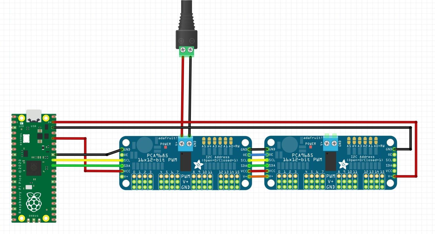
i guess my main uncertainty is if i can use the output v+ pin from the servo driver board as input to the pico's VSYS pin... on one hand, the power pin description https://learn.adafruit.com/16-channel-pwm-servo-driver/pinouts#power-pins-2980404 doesn't really sound appropriate for powering the pico, but on the other hand, the fact that you can chain the drivers like this https://learn.adafruit.com/16-channel-pwm-servo-driver/chaining-drivers makes me think it could be possible
supple pollen
Yes, that should work. Normally it can cause problems to run your logic from the same supply as electrically noisy devices (such as servos), but the Pico regulates VSYS down to 3.3V internally, which would probably provide sufficient isolation. You could take V+ from the near end instead of running it all the way around. You don't need to provide two ground connections (and in fact, it can cause problems if you do).
left grove
What happens if those wall-brick PSUs get back-powered?
(as it is in the image, the PC usb port is protected against back-powering but the wall PSU isn't. When you plug in both usb into the Pico and the PSU into the wall at the same time)
woven bluff
The output of SMPS has rectifier so it won't get back-powered.
left grove
Thanks, good to know
real palm
thanks everyone 😁
 tame kestrel
Is it possible to connect multiple I2C devices like that, specifically NeoKey 1x4?
I want to design a PCB where I could plug them but I am not sure whether to connect one to another or do something like in the second image, where VIN and GND are shared among all I2C devices.


 tame kestrel
humble swift
tame kestrel
humble swift
yes yes, but can I do it using the pin holes instead of the cable, I am not very familiar with electronics and do not know whether is it the same type of connection
humble swift
ooooh...you know im not sure, someone who can read the layout can probably tell you
jade wedge
Yes, the through hole pin positions are usable just like the STEMMA/I2C sockets. Note that there are 6 pins instead of 4. This is because in addition to the typical I2C connections you can source a small amount of 3.3v power off the "3" pin, and the INT pin is an interrupt pin that will go low when a button is pressed so you don't have to constantly poll the board for keypresses.
tame kestrel
jade wedge
Yes, the through hole pin positions are usable just like the STEMMA/I2C sockets....
That part about INT pin is very interesting, I will have to look into it. Thank for your response, so if I am correct this should work, right?
 jade wedge
Yes. From what I understand about the board based on the tutorial pages and the schematic, that should work just fine.
tame kestrel
jade wedge
Yes. From what I understand about the board based on the tutorial pages and the...
Thank you  , I am just starting with electronics and this is very new to me.
 inner rampart
Does the 32 +0, -0.25 mean the tolerance might only be smaller than nominal and not bigger than the nominal ?

 gloomy garden
Hardware gurus,
I will preface by stating I have no background in hardware or circuit design so please consider me a blank slate on this front. Based on a paper titled "LEDs driven by AC without transformers or rectifiers" (https://www.nature.com/articles/s41598-020-80617-2), I have created a schematic for my proposed circuit (below). The capacitor (C1) is a .22 uF 630V bidirectional ceramic capacitor, the LED a standard cylindrical 3mm green LED, the diode (D1) a 1N4004 rated at 400v / 1A, and the transient voltage suppressor (D2) a bidirectional P6KE series diode rated at 376V / 600W. I estimated the capacitor size based on an equation in the paper, and sized the diodes based on descriptions in the paper and some conservative estimates on my part. The purpose of the 1N4004 diode is to replace the second LED in the original design since I can't really accommodate a second LED in my application.
With my acknowledging that this is deadly line voltage stuff and I intend to take what I hope are adequate precautions for prototyping (e.g., GFI, sealed low-amperage fuse, enclosure for the prototype, etc.), my questions are:
- Can you see anything wrong with the schematic?
- Is using the 1N4004 in lieu of a second LED for the AC reverse cycle inappropriate, and is there a different diode that would be a better replacement for the second LED?
- I tried to fully understand how a TVS diode works / is specified and found a white paper from TI that was helpful, but I am not confident that I have selected the most appropriate TVS diode for my application and any advice greatly appreciated.
I tried to keep this somewhat concise, but if you need more information or links to datasheets for the specific components I am using, I am happy to provide them. Thanks in advance for any guidance you can provide before I solder and power up the prototype!

And in case it helps, the specific application is LED indicator lights for individual circuits on an electrical panel on our boat. The panel has 240VAC / 120VAC and 24VDC sections. The 24VDC LEDs work fine with just resistors, but the panel was originally designed to use just resistors on the AC sections as well and the LEDs fail in short order, I believe due to reverse flow through the LED on the AC circuits. I am trying to avoid using resistors at all on the AC indicator lights because they waste a lot of power (relatively speaking). Thanks again for any help!
supple pollen
inner rampart
Does the 32 +0, -0.25 mean the tolerance might only be smaller than nominal and ...
Yup. Since these are intended to be mounted side by side, they're stating that they'll fit if you do so.
supple pollen
gloomy garden
Hardware gurus,
I will preface by stating I have no background in hardware or c...
You don't really need the TVS, the diodes will clip the voltage for you. I'd use a low forward drop signal diode like a 1N4148 instead of a 1N4004, but it would probably work any way. You might want to put a small series resistor to limit peak current (and possibly a fuse in case things go horribly wrong: many commercial capacitive droppers like this use a 10Ω fusible resistor to do both).
gloomy garden
Thanks @supple pollen, I sincerely appreciate your help and will order some 1N4148 diodes instead. Regarding the TVS, the paper I based my design on put the fear of surge in me by saying "Potentially more serious are surges in forward current at switch on: If the assembly is connected to the mains when V(t) is in the interval (-Vc, Vc), then initially the current flow is zero. However, if for instance V(t) is outside this voltage range and the capacitor is uncharged, then there would be a large current surge until the capacitor is charged. In fact, the worst case would be switch on when V(t) = V0, the capacitor happens to be reverse charged to -V0, and the LED chain is short, e.g. 1 LED (as in my case), so that Va is approximately 2V0. In that event, the forward current on attaching to the mains with V0 = 325V would be approx. 2V0/R or 650/30 or 20A, for a time of order approx. 3x10⁻⁵ seconds when using the LED's differential resistance for R." Is this the scenario for which you proposed using the series resistor in to limit peak current? They suggested a P6KE series TVS diode to handle this potential switch on surge. Thanks again for your guidance!
supple pollen
That may well be the case, the TVS can't hurt.
gloomy garden
One last question... I am planning on implementing this on a perfboard with 0.1" hole spacing that I cut to size to fit my electrical panel and point-to-point wiring my layout. I know I need to be meticulous with my soldering to prevent bridging / arcing, but are there any minimum distances I need to enforce between my "traces" since this will be used at line voltages (i.e., 120VAC and 240VAC)? I did some searching online and most of what I found was "don't do it" and no actual information on trace proximity limitations for different voltages. Given my skillset, I don't think I have any better options than this approach if I want to fix the electrical panel. I am comfortable soldering, and while it can be a bit tedious I do enjoy the point-to-point wiring, but I don't want to do something that is inherently unsafe like for example running traces in two adjacent rows of holes if that is too close.
supple pollen
For a marine environment, you probably want to both pay attention to anti-tracking and creepage, as well as probably a conformal coating. For mains work, I'll sometimes remove an entire row of conductors between circuits for better isolation.
gloomy garden
Thanks again for the help, researching the terms "anti-tracking", "creepage" and "conformal coating" is answering my questions. Sometimes you don't know what you don't know...
minor flax
can i2c and uart share a bus?
supple pollen
It's a little tricky, as asychronous serial drives the signals both high and low, and I2C only drives signals low (with a passive pull-up), so contention won't cause drivers to have a tug of war. So if you were sending asynchronous serial data and an I2C peripheral thought it was being addressed and tried to respond, you could get a conflict. However, if you could protect against that, the I2C pull-ups wouldn't keep the asychronous serial signals from working.
jade wedge
My thought on preventing conflict for that would be to use a logic level converter. Not for the level conversion, but for the fact that they typically have an output enable pin so you can effectively disconnect the other side.
However, upon looking into options, the auto direction sense ones don't seem to work well with I2C. The I2C safe option that Adafruit has doesn't have an OE pin, defeating the whole point. Though, maybe you could fake it by disconnecting the power?
supple pollen
The best approach probably depends on the particular problem you're trying to solve. Is it a lack of GPIO, not enough connecting wires, swapping peripherals on the same connector, something else?
lime herald
There are I2C controlled UARTs like the PI7C9X1170, so you could just use I2C and stick a UART on the I2C bus.
sweet cairn
How do I test if this circuit is working properly? Rn audio isn't working for me

This is based on Adafruit's PAM8302A Chip
supple pollen
That's pretty much the data sheet circuit, it seems like it ought to work. What is the supply voltage? What is the speaker impedance?
distant raven
sweet cairn
How do I test if this circuit is working properly? Rn audio isn't working for me
Is this a stand alone board? Or part of a larger schematic
sweet cairn
distant raven
Is this a stand alone board? Or part of a larger schematic
Part of a larger schematic
This is the entirety of it. I messed up the design in some other places, so just wanted to ensure this is fine
sweet cairn
supple pollen
That's pretty much the data sheet circuit, it seems like it ought to work. What...
I see. I hope there are no errors the.
This is the datasheet for the buzzer
Supply voltage is 3.3v (but can be changed to 5v too)
Cool resistance is 12-18 ohms according to the datasheet
The firmware I wrote for this (QMK keyboard firmware) was tested by someone else on the same basic hardware (PAM8302A, not sure what speaker/buzzer they used) and it worked. So I'm mostly sure it's a hardware issue. Just not sure how to diagnose it or figure out which part of the circuit is causing an issue
minor flax
minor flax
can i2c and uart share a bus?
Thanks for the replies madbodger, lolly, and romkey I actually discovered unpopulated resistors coming out of a bus switch, the populated parts go to uart, but the unpopluated part goes to i2c, I was just curious if I popluated the i2c part if it would work. I agree that in theory they shouldn't overlap but I'm gonna try wiring it up to see what happens 🙂
supple pollen
sweet cairn
Supply voltage is 3.3v (but can be changed to 5v too)
Hmm, should work on 3.3 or 5V. That's not really a speaker as much as a beeper, it's designed to be driven with a 4kHz square wave, I'm not sure what it would do with an audio input.
sweet cairn
Yeah i have a slide switch that changes power supply between vcc and raw pins.
I don't think it's getting an audio signal. I think it's PWM signals. Anyways, Adafruit Macropad uses something similar and it works - they use a different amp ic and a less louder version of the buzzer
supple pollen
A PWM amplifier would likely not work well with with a PWM input
woven bluff
if you convert your audio to PWM or FM, the beeper can play basic tone, sounds like 8bit
you can just use ADC+PWM on the MCU to do it. just map the input voltage to PWM counter values. then attach an IRQ to change PWM counter registers on ADC completion.
inner rampart
Hi all. I'm trying source these types of 8 pin plugin headers. Square header on the male side, circular hold on the female side.
 humble swift
try machine pin headers
golden wasp
Hi, Would you please help me? Would it damage a bare Ultra Skinny NeoPixel 1515 LED Strip 4mm if I were to use hot glue to fix it in place? (product page: https://www.adafruit.com/product/4368) I have a 4 mm thick wooden board into which I've cut a 15 cm diameter cylindrical hole. In the middle of the hole I have a 4 mm tall polycarbonate cylinder having a few millimetres less diameter than the hole. Thus there's a few mm gap between where I intend to put the LED strip sideways. The pieces are hand cut with hand tools thus the surface is somewhat uneven. What would you recommend? Thanks in advance, Peter
jade wedge
Unless you have a particularly hot glue gun, and expose a single section to it for an extended period of time, you're rather unlikely to damage anything. Hot glue guns are often between 250-375 degrees fahrenheit, while flex boards can generally tolerate up to around 350. Slightly higher for short periods.
Also note that Adafruit themselves appear to use hot glue to seal the ends of certain neopixel strips.
Also now part of me wants to use a pair of those strips to upgrade an existing project I have. I also know where to get reels of heat shrink tube, so I can protect them.
Hmmm...
Oh, quick calculation, I couldn't use them anyway.
At least not with the current build, but when I upgrade the microcontroller...
woven bluff
inner rampart
Hi all. I'm trying source these types of 8 pin plugin headers. Square header on ...
those are low profile machined pin sockets, they are lower than the common cheap square 2.54mm sockets, retention force is also higher. it's cheaper to buy them in full length (64pins) and then cut it yourself.
inner rampart
@woven bluffthanks. here is the part number i found SMC-1-08-1-GT
woven bluff
anyone know the Vrev requirement of the diode in DZ snubber?

does D1 need to withstand the voltage of the secondary side?
 pastel night
z1 says 24 volts... this is a clamp on secondary voltage. D1 should be rated to ~2x primary voltage max(36V), part says 70V
woven bluff
humm the datasheet says Z1 <= 65V(max Vds for the internal FET)-Vin(max), and D1 > SW voltage
doesn't seem Z1 and D1 is related to the secondary side
supple pollen
In general, the secondary side will have 4x the voltage of the primary side due to the winding ratio. However, inductive circuits do a variety of interesting things, so the switching spike on the primary side can still be considerably higher than the supply voltage.
So while you're correct the Z1 and D1 (which are on the primary side) are not related to the voltage on the secondary side, they do have to contend with the inductive spike voltage of the primary side (which is, in fact, what they are there for).
woven bluff
so basically if the spike pops Z1, then it will be let through D1
I'll just use a SiC diode just to be sure
supple pollen
Z1 doesn't "pop" destructively, it will just conduct in the forward direction if the voltage is higher than its bandgap (about 0.6V for silicon) or if the voltage in the reverse direction is higher than its zener voltage. The forward conduction is blocked by D1 (which you want, so it doesn't short out the primary), so its main function is the zener function to provide a safe path for inductive switching spike caused when the primary is switched off.
I don't think there's any advantage to using SiC in this position
Basically, the two diodes act together as a "one-way zener"
woven bluff
yeah, I meant the breakdown, not the "pop"
so D1 does not have to withstand the spike
supple pollen
For lots of details without getting too technical, I recommend AN25 "Switching Regulators for Poets", by the inestimable Jim Williams https://www.analog.com/media/en/technical-documentation/application-notes/an25fa.pdf
No, D1 merely has to withstand the supply voltage, to block forward conduction through the zener, so the current is routed through the transformer.
woven bluff
well, doesn't matter now. I cannot source the 1:100 SMPS transformers on LCSC. so back to the one stage to 200V madness
supple pollen
For high boost like that, I either source transformers separately (they're specialty parts), use an inductor based circuit (if I don't need an isolated supply), or build my own transformer.
What are you trying to accomplish?
woven bluff
12->200V with MAX1771 works well for half a year, but I noticed intense coil whine recently
nixie supply alternative to my currently one stage boost
supple pollen
Ah, sounds like vacuum tube/nixie voltages. Yeah, there are a host of inductor based designs for that realm, using a few different chips (555 and MC34063 are popular as well). The LT chips are useful candidates too, but as you've seen, tend to be aimed at transformer-based designs.
These days, I just usually buy off the shelf nixie supplies (I'm fond of the TaylorEdge ones, I've heard the Yan Zeyuan ones are nice too)
woven bluff
I'm fine with my inductor based design, but getting 5->200V let's me get rid of the 12V rail
supple pollen
You could say the subject interests me...

You can get 5->200V, but it requires careful layout and parts selection
woven bluff
we conversed multiple times regarding this subject
for my next divergence meter, I want a radar to replace the PIR sensor for human detection
they are normally quite expensive, but I found a cheap one on ICSC https://www.lcsc.com/product-detail/Sensor-Modules_HI-LINK-HLK-LD2410B-P_C5183132.html
supple pollen
I've seen some surprisingly affordable 66GHz ones for sale lately. They're getting popular for various people sensors, which seems to be driving the prices down, which makes them popular, etc.
jade wedge
I thought about making a Nixie clock at one time. I think I still have the listing for some original Russian driver chips in my Amazon list.


 humble swift
might help to say what the board is from
woven bluff
jade wedge
I thought about making a Nixie clock at one time. I think I still have the list...
there are modern drivers such as HV5530
woven bluff
ocean coyote
https://cdn.discordapp.com/attachments/828106881687879683/1188750947988537375/rn...
looks like DFN 10 4x4mm
 lusty pulsar
Hi, I'm having a bit of a problem. I'm trying to connect jump wires to a raspberry pi with an adafruit voice bonnet connected to the pins (se piture). I'm using a 11 mm header between them and it gives room for attaching jump wires. The problem is that when I try to connect jump wires they keep sliding off as they dont properly attach to each other. My theory is that the male pins that I'm trying to connect are too short as they are only 5 mm long in comparison to the 6 mm on jump wires. Does anyone know how to fix this or do i need to solder them to keep them in place?
 woven bluff
supple pollen
I've seen some surprisingly affordable 66GHz ones for sale lately. They're gett...
woven bluff
supple pollen
I've seen some surprisingly affordable 66GHz ones for sale lately. They're gett...
can you share the part number?
supple pollen
I don't have that handy. I'd seen a link in a hobbyist magazine a while back but I don't have that article handy.
 gentle fractal
HI all, I have a these LEDs BTF-LIGHTING 5050 RGBW RGB+Cool White, which are analog 12 V LEDs and DUSKTEC LED Driver 12V 100W PSU. On LED strip there are + and RGBW markings. From few video I have seen, the + on LED is to be connected to + of PSU and - of PSU can be connected to RGBW pins. Is that correct way of powering those LEDs? IS there any additional circuitry required between LED strips and PSU?
latent jungle
gentle fractal
HI all, I have a these LEDs BTF-LIGHTING 5050 RGBW RGB+Cool White, which are ana...
If the strips have current limiting resistors built into them, then Yes.
gentle fractal
latent jungle
If the strips have current limiting resistors built into them, then Yes.
how can I find out tht?
supple pollen
You should see the resistors (small black rectangles) between the LED packages (larger white/yellow squares)

Since they're marketed as "12V" LEDs, the presumption is that the resistors to make the current flow correct for 12V are present.
cursive sentinel
Ideally they would put several in series, since it is less wasteful that way.
 marsh rain
I am having trouble getting into the USB boot mode on a fresh RA4M1 chip, I have MD pulled low but the device does not show up in COM ports. Does anyone know what I might be missing? This is the first time I have designed a board with an MCU
supple pollen
Is the clock oscillating?
marsh rain
I'm just using the internal clock similar to the R4, but I believe so? I can upload code with a J-Link and it is blinking an LED
Is there away to adjust the internal clock settings?
supple pollen
I'm not familiar with that chip, generally it's fuse settings to select the clock options. Does it have native USB?
marsh rain
Yea, the datasheet says USB full-speed
supple pollen
Okay, so you don't have a separate USB-serial chip?
marsh rain
Yea, I am just using the on-chip USB
supple pollen
Does the USB enumerate?
marsh rain
supple pollen
Does the USB enumerate?
What do you mean by enumerate
supple pollen
When a USB device is attached to a system, the process by which it recognizes and identifies the device is known as "enumeration". It's the first step in the chain toward providing a serial device via USB.
marsh rain
Ah, as far as I can tell no, my computer doesn't seem to recognize it and nothing shows up in the device manager like an Arduino would
supple pollen
Sounds like you're using Windows and unfortunately I don't know how to debug USB enumeration on windows.
marsh rain
No worries, thanks for trying
inner rampart
I'm trying to design a board with the esp32c3-mini which supposedly has a usb driver built in. The reference design doesn't have a serial to usb (cp210x) chip on it but I don't know if it this design allows for programming over the usb interface. Because some of the adafruit boards with this same esp32 chip have a cp210x on the board, but why would it have the cp210x if usb is already built in ?
 inner rampart
well actually there is one adafruit board that uses the exact module and is the risc rust board which does NOT have the cp210x chip. so maybe i'll base my design off that board ( https://www.adafruit.com/product/5787 )

ESP32-C3-DevKit-RUST-1 is an entry-level RISC V development board equipped with the ESP32-C3-MINI-1, a powerful, generic Wi-Fi + Bluetooth LE MCU module that features a ...
gentle fractal
supple pollen
You should see the resistors (small black rectangles) between the LED packages (...
I thought those were resistor, but wasn't sure. Thanks these do have those black blocks with R G B W written on them
cursive sentinel
Each color needs its own resistor.
lime herald
inner rampart
I'm trying to design a board with the esp32c3-mini which supposedly has a usb dr...
Yes, you can program over the USB port, as well as JTAG debugging. Some Espressif devkit boards have an additional USB/UART chip and a second USB port for it for debugging/flexibility.
lime herald
inner rampart
well actually there is one adafruit board that uses the exact module and is the...
That's actually an official devkit board from Espressif, the manufacturer of the ESP32, that Adafruit resells. It's not an Adafruit designed product.
inner rampart
Oh right. That's from espressif.
woven bluff
is it possible to use active cooling on D2PAK?
supple pollen
Sure, why not? It has a thermal pad.
woven bluff
but the pad is soldered to copper
woven bluff
and aluminum board is expensive
 last prairie
The answer is probably no but should I connect all the ground pads on this connector to ground, or only one?
 woven bluff
the doc should say which ground pins are power and which pins are signal
oh, you have a type-c, you can connect them together
tough matrix
connect all gnd to ground
 knotty tiger
i think sometimes the shield has some filtering to signal ground for EMI or ESD reasons
woven bluff
those 4 GND pins are not shield. I think the shield is pin0