#help-with-hw-design
1 messages · Page 24 of 1
 supple pollen
 tough matrix
@split obsidian A lot.
Digikey has a special section for "BPJ transistor arrays": https://www.digikey.com/en/products/filter/transistors/bipolar-bjt/bipolar-transistor-arrays/277
Most of them are SMT, but there are some DIP as well, e.g. https://www.digikey.com/en/products/detail/stmicroelectronics/ULQ2003A/599595
(these are Darlington pairs rather than single NPNs, though)
For quad array of 2222, check this: https://www.digikey.com/en/products/detail/central-semiconductor-corp/MPQ2222-PBFREE/5018735
(it is $5, which IMHO is ridiculously expensive for a basic transistor array, but on the other hand, if you only need one such, it is not a big deal...)
 hasty solar
newbie question: are there guides i could read about manage wiring and cables when wiring together a bunch of very small components? i don't really know what to google for this
still getting my head around different types of transistors, transistors vs MOSFETs, how to size resistors, etc, and just wanted something relatively plug and play for this project. i'm planning to grab one of these: https://www.adafruit.com/product/5648
Sparky the Blue Smoke Monster shows up whenever the magic smoke is let out of an electronic component. And his very favorite is whenever folks first start with electronics and robotics: ...
 clever shadow
My understanding is this 680ohm resistor will limit the current to ~17mA on this large capacitor, but I'm unsure as to what sort of power rating is needed on the resistor. My power source has a maximum draw of 50mA - if this limits the charge current to 17mA but then wastes the rest as heat, them I'm not quite achieving my goal here.

 cursive sentinel
It's to prevent excessive inrush current (during initial charging the cap is almost a short).
clever shadow
cursive sentinel
It's to prevent excessive inrush current (during initial charging the cap is alm...
Right - but does the resistor just dump the power instead?
 tough matrix
the schematics shows 12V power symbol before the resistor, so current to 12v bus doesn't go through resistor.
Presumably, other places in schematics connect to that same 12v signal
the resistor only limits the current to the capacitors, not to other parts of schematics
cursive sentinel
Yeah, it really depends on the type of load connected downstream. The power dissipated by that resistor is proportional to the square of the current (P = I²R). The worst case scenario would involve drawing a large, continuous current so that the capacitor is always charging, which would result in the resistor being more or less in series with the load.
However, if the load is "bursty" (dissipating a large amount of current briefly and then recharging) the energy loss through the resistor will be minimal.
clever shadow
cursive sentinel
However, if the load is "bursty" (dissipating a large amount of current briefly ...
Indeed at power-up, the voltage is 12V on one side and 0V on the other which is worst case. The voltage will start to rise, so the power dissipated will be less, right?
This is the only place 12V is used. It is stored in the capacitor, and then goes to a bucking regulator to get down to 3.3V.
cursive sentinel
clever shadow
Indeed at power-up, the voltage is 12V on one side and 0V on the other which is ...
At the point you're driving a buck regulator why not just connect it directly to the 12V?
clever shadow
cursive sentinel
At the point you're driving a buck regulator why not just connect it directly to...
Not sure I understand. This feeds directly into the buck afterwards.

 slow plover
Anyone have advice for securing PCBs with very little clearance? I have some areas with clearance for a ~3mm diameter zone where I could put very small standoffs, and the back side of the board is relatively unoccupied.
supple pollen
slow plover
Anyone have advice for securing PCBs with very little clearance? I have some are...
Sometimes something like this can be useful https://www.adafruit.com/product/1116

Having difficulty attaching a PCB? This kit is especially useful when there are no mounting holes - as with the original Raspberry Pi. Instead of gluing, taping, epoxying, etc. use these ...
slow plover
supple pollen
Sometimes something like this can be useful https://www.adafruit.com/product/111...
unfortunately, I think even those are a touch too big
tough matrix
just use a single male header pin instead of standoff?
or test points like these?
https://www.adafruit.com/product/3825

Testing is an important step in board manufacturing. And it can be super tricky on a fully populated PCB. So how can you test connections when you have an assortment of components ...
cursive sentinel
Test points are nice if you want to clip a scope to it. Otherwise, single through hole headers are fine.
tough matrix
I like how JLCPCB words their questions regarding orders.
*Well got your order with many thanks.
Sorry to bother you, but there is one thing that we want to confirm with you before proceeding.*
 rustic linden
That's exactly how you'd do it
 ornate sleet
yup, each LED gets wired to VCC and GND for power, then you make a chain connecting each one's data-out pin to the next's data-in pin
at the first DIN comes from the MCU, ofc
beware the specification (at least for some similar parts) is something like 3.7-5V (and power and data signals should also be the same level, or very close), so if your MCU's GPIO works on 3.3V, you may want/need a level shifter to get it at 5V
tho, fwiw: i used sk6812-minie (or a similar part name) with RP's 3v3 output for data and 5V power and it works just fine
i would have used a power plane to get either VCC or GND "magically" connected instead of using traces, but looks right
 inland jungle
why don't you rotate the top row leds 180 degrees, that way you can consolidate a power bus, and the data wiring becomes easier
 bright thistle
You're using smd components, so your choice is aut aut (xor), you cannot have both planes on the same side, iirc.
Personally, I'd make it a ground plane, but it's probably because I'm used to seeing the - on cars connected to the chassis instead of going directly to the circuit.
ornate sleet
bright thistle
You're using smd components, so your choice is aut aut (xor), you cannot have bo...
they could use vias to "jump" the back's plane into the needed pads on the front face (no idea how good of an idea that is, tho... im no EE :p)
bright thistle
Also, but here I'd need somebody more expert than me to either confirm or rectify, running the data traces thru the gnd plane would give them some sort of shielding
bright thistle
ornate sleet
they could use vias to "jump" the back's plane into the needed pads on the front...
Uh... I don't know if it's a good idea to have a pad with a hole in the middle for smd, maybe having the via and then a smol trace would be more "kosher", but guess you'd lose the whole point of a power plane. At this point I'd rather use PTH components.
ornate sleet
yeah, i meant close enough + small trace, but again, no EE (:
bright thistle
ornate sleet
yeah, i meant close enough + small trace, but again, no EE \(:
Ditto, no EE, just a lousy foreman, and an unregistered one to boot, so my word is as worth as anybody else's 🙂
 surreal tangle
You might add some 100nf decoupling caps like the datasheet shows...
 rough smelt
Hey guys has anyone used the nrf feather? I saw it had internal pull-ups. Is it any good? I have 6 buttons for my project and need to know if i need to power it or can I just wire it right to the pin of the mcu
 vast flume
bright thistle
Uh... I don't know if it's a good idea to have a pad with a hole in the middle f...
vast flume
bright thistle
Uh... I don't know if it's a good idea to have a pad with a hole in the middle f...
Nah its fine to throw vias onto pads. I do it all the time
 latent jungle
Via-in-pad is fine if you're not going to do mass production. (statistically, it can cause problems. But it's not meaningful until you're talking thousands.)
vast flume
latent jungle
Via-in-pad is fine if you're not going to do mass production. (statistically, it...
Just curious, what issues can it cause? Wanna just have it in mind for my future troubleshooting headaches lol
latent jungle
vast flume
Just curious, what issues can it cause? Wanna just have it in mind for my future...
Solder can wick into the via causing a poor joint between lead and pad, or a bump on the other side. (The solution is to plug the vias, but it is expensive in low quantity.)
vast flume
latent jungle
Solder can wick into the via causing a poor joint between lead and pad, or a bum...
Ah I see. Always wondered what plugged vias were for
 paper vale
Hello. why I get error here ? Nets with only pin
 bright thistle
What kind of error?
vast flume
Wheres this net on the right going to @paper vale

 heavy jasper
Do you have +VIN connected somewhere else?
The "net with only one pin" means "you named a net, but it's not connected to anything else, that seems odd"
and at least for the schematic I see here, the only named net I see that has only one connection is +VIN
e.g. +VBAT_FB is connected to R1, R2, and C2
(realized I mentally auto-filled the "one" in your sentence above but I suspect I'm still right)
 pure gorge
So a while back I tried repairing a reel to reel that I thought had a short due to a specific resistor getting really hot. But I cut one of the leads of the resistor and it made the whole metal casing shock me when I touched it. So now I'm wondering if that resistor has some purpose related to grounding, and maybe it's supposed to be shorted like that.
Anyone have any idea if this is normal? Or is it actually a short?
pure gorge
Nevermind, I seem to have reassembled it wrong somehow
 cedar cradle
So I have a solenoid and esp32 powered by a single 18650 battery. My problem is that when I trigger the TIP for the battery to power the solenoid, little to no power goes through the board because all the current goes through the near zero resistance in the solenoid loop, not the board. Any ideas on how to keep the board powered while the solenoid is triggered?
paper vale
vast flume
Wheres this net on the right going to <@657254742862594089>
MCU pin in another sheet
paper vale
heavy jasper
Do you have +VIN connected somewhere else?
no. I want it to be connected to the drain of the PMOS only
supple pollen
cedar cradle
So I have a solenoid and esp32 powered by a single 18650 battery. My problem is ...
You may need a current limiting resistor in the base circuit
 candid orchid
From measuring the voltage drop with the ADC, how can I calculate the resistance of the 5k resistor (this is a variable pot) in this three resistor divider?

 distant raven
candid orchid
From measuring the voltage drop with the ADC, how can I calculate the resistance...
distant raven
candid orchid
From measuring the voltage drop with the ADC, how can I calculate the resistance...
Kirchhoff’s voltage law is usually what you would use
bright thistle
candid orchid
From measuring the voltage drop with the ADC, how can I calculate the resistance...
Resistors in series act like their sum, and so do their voltages. Apply Kirchoff's law.
I'd say @distant raven and me just did some 70% of your assignment with just those two hints alone.
 frosty scaffold
Is this arrangement problematic? The resistor is a pulldown resistor for an ESP32's 3.3v input and the capacitor is a filtering capacitor.
 latent jungle
frosty scaffold
Is this arrangement problematic? The resistor is a pulldown resistor for an ESP3...
latent jungle
frosty scaffold
Is this arrangement problematic? The resistor is a pulldown resistor for an ESP3...
What are you worried about?
The larger concern I see is using traces for GND and not a copper pour / GND plane.
 worldly schooner
I don't see a connection between GND and R1, if that's supposed to be a pulldown.
frosty scaffold
worldly schooner
I don't see a connection between GND and R1, if that's supposed to be a pulldown...
Apologies, I miswrote. It’s a pull-up resistor
frosty scaffold
latent jungle
What are you worried about?
I ordered this PCB and I have problems outputting 3.3v to my ESP32. I can provide a photo shortly
latent jungle
A schematic problem makes more sense.
heavy jasper
paper vale
no. I want it to be connected to the drain of the PMOS only
If you want it to be connected only to that PFET (presumably because you're managing the power connection in layout - though I'd encourage you to make a libary component for whatever power connector you're going to use / specific via geometry you want for banana plugs or something) and not throw an error, I think you have a few options, the most scalpel-like is to place a "no ERC object" on that pin (looks like a little red X, basically tells the compiler "ignore this")
I'm not sure which version / tool you're using - at least in full Altium you can specifically scope the no-ERC marker to only ignore single-pin nets, which is nice since you know it won't accidentally cover up any other types of errors.
As an example, on my schematics I set "unconnected pin" as a compilation-blocking error, then I know that for every pin on every chip in the design I've either specifically made a connection, or specifically reviewed, decided I didn't want a connection, and marked it with a "no-connect error" specific no-ERC marker
paper vale
heavy jasper
If you want it to be connected only to that PFET (presumably because you're mana...
I saw the options to disable the nets only pin but I would not like to do it. Your recommandation is good, I will add a connector symbol to that pin so that the error will disappear without deactivating anything. Thanks
 last prairie
When there is a symbol of an arrow with something like VIN I can assume that all identical symbols are joined? Right? In the second image, I just connected all the “VIN” things together to show what I mean…

 distant raven
last prairie
When there is a symbol of an arrow with something like VIN I can assume that all...
distant raven
last prairie
When there is a symbol of an arrow with something like VIN I can assume that all...
This is usually a fair assumption
 fickle patio
I’m struggling to understand this circuit, from the Pi Pico datasheet. It’s meant to switch off a battery connected to VSYS when there is power supplied from VBUS.
Im currently using a Schottky diode to prevent back charging the battery, but this causes a .3v drop, which I want to reduce.
The use of the pmos is supposed to improve this: “The P-FET should be chosen to have low on resistance, and therefore overcomes the efficiency and voltage-drop issues with the diode-only solution.”
Here’s my question: in this circuit, doesn’t the current flow through the MOSFET’s body diode, thereby incurring a voltage drop anyway? When I simulate the circuit I see about .3v drop from drain to source.
 distant raven
fickle patio
I’m struggling to understand this circuit, from the Pi Pico datasheet. It’s mean...
distant raven
fickle patio
I’m struggling to understand this circuit, from the Pi Pico datasheet. It’s mean...
It’s effector a source switch. Adafruit does this to switch between battery and usb power to the onboard regulator.
When powered off, it blocks any voltage flowing back through the mosfet that could potentially damage what’s connected to VSys, when on the mosfet acts as a small value resistor allowing power to flow freely
fickle patio
distant raven
When powered off, it blocks any voltage flowing back through the mosfet that cou...
Thanks for looking into this with me. You’ve provided a summary of the basic concept, which I think I already have a good handle on.
Did you see my specific question about voltage drop?
distant raven
The voltage drop is expected, sort of a characteristic of mosfets
Effectively a transistor is two diodes joined at their complimentary junction. So it makes sense that there will be some voltage drop crossing the gradient between source and drain
fickle patio
distant raven
Effectively a transistor is two diodes joined at their complimentary junction. S...
So, my current solution uses a simple diode, but that solution loses .3v. According to the datasheet, the MOSFET solution is superior because it:
“…overcomes the efficiency and voltage-drop issues with the diode-only solution.”
And indeed- when I use a MOSFET, I’m used to seeing a very low voltage drop when the current flows from source to drain. In my simulator, I see a drop of just .05v in this configuration.
However, I’m the circuit we are discussing, the battery current flows from drain to source, and my simulator shows a .3v drop, the same as with using a simple Schottky diode.
What am I missing? How is using a pmos here better?
distant raven
Because it allows you to do source voltage control and provides better overall protection for your source coming through the mosfet
The mosfet also ensures lower leakage back to your VSys or battery. Which minimizes potential damage
Kind of saying the same thing twice but overall it’s just a smarter solution because you actually can disable one source over the other
fickle patio
distant raven
Kind of saying the same thing twice but overall it’s just a smarter solution bec...
Thank you.
Is there no way to safely have a battery attached without losing .3v?
distant raven
You need some protection and that usually comes at the cost of some voltage drop
Some are better than others
I’ve got a battery hooked up to my feather and there is virtually no drop from source to drain
My batter has 3.06V at current charge level and from the other side of the mosfet it’s the same 3.06V
If curious, my board uses this mosfet instead of the DMG3415U that Adafruit uses https://aosmd.com/res/data_sheets/AO3415A.pdf
fickle patio
distant raven
I’ve got a battery hooked up to my feather and there is virtually no drop from s...
From source to drain, a MOSFET like the 3415A has a very low on-resistance. Makes sense that the voltage drop is minimal, and I’d love to achieve the same result.
But! Doesn’t this schematic show the battery connected to drain, not source?
 distant raven
fickle patio
From source to drain, a MOSFET like the 3415A has a very low on-resistance. Make...
distant raven
fickle patio
From source to drain, a MOSFET like the 3415A has a very low on-resistance. Make...
Yes, that’s how it’s supposed to be used in load switch configurations
fickle patio
distant raven
Yes, that’s how it’s supposed to be used in load switch configurations
I think I’ll have to attempt reading the MOSFET chapter of Art of Electronics again because I’m still very confused lol.
I thought at first you were saying that a voltage drop is unavoidable, but then when you measured your own circuit you observed no measurable drop.
Your battery is connected to the drain, with the load connected on the source side?
I appreciate your efforts in helping me understand so far 🙂
supple pollen
distant raven
Effectively a transistor is two diodes joined at their complimentary junction. S...
A bipolar transistor is sort of like two diodes, but a MOSFET is more like a variable resistor.
cursive sentinel
That's kind of true if you squint enough. A BJT doesn't really behave like a pair of diodes, even though the physical construction is similar.
distant raven
It’s just an analogy from a text book 😛
It’s how they describe the general construction
distant raven
supple pollen
A bipolar transistor is sort of like two diodes, but a MOSFET is more like a var...
A variable resistor whose resistance is changed by the driving voltage and in certain circumstances frequency
RdsOn changes with frequency and voltage according to data sheets 😛
Which makes sense
But you’re talking about something else
supple pollen
It's principally dependent on voltage, so saying it's changed by the driving frequency could be confusing
distant raven
🤷♂️
To be clear I did say that the p channel mosfet acts as a small value resistor when on so I got the basics right
Unfortunately attempting to use terminology to make things digestible doesn’t always pan out well
(No pun intended)
cursive sentinel
distant raven
A variable resistor whose resistance is changed by the driving voltage and in ce...
And temperature
distant raven
And my sword

😬
I’m using ChatGPT to have some fun seeing if it can do complex math like calculating the resistor necessary for a 600MHz cutoff to support 1.2Gbps optical communication with a 0.2pf feedback capacitor
It says a 1322.38ohm resistor would be necessary given a 4GHz GBW
 unreal flax
Off the top of my head I have no idea if that's correct or ridiculously silly...
distant raven
Math seems a little off? But not too far from what I can recall
 cosmic charm
hi guys, plase help me with this problem https://github.com/espressif/arduino-esp32/issues/8738 . Thanks!

GitHub
Board custom board Device Description custom board esp32-s3 based on s3fn8 Hardware Configuration VRN.pdf Version v2.0.13 IDE Name Arduino IDE Operating System Windows 10 Flash frequency 40mhZ PSRA...
latent jungle
cosmic charm
hi guys, plase help me with this problem https://github.com/espressif/arduino-es...
You already got extensive help on the KiCad server.
You should at least mention the troubleshooting and changes you’ve made here, so people don’t waste time repeating information.
 latent drum
Howdy! I'm working on a project that requires some very basic communication between two boards (a metro mini and a feather 328p). I'm setting it up with I2C. Since the metro mini is running 5V logic (and must(?), I have a 5V PIR connected to it that's not pictured) and the 328p is running 3.3V logic, I figure I need a logic level converter between the two. I dug one up from my box-o-stuff that is a 4-channel, bidirectional converter (it has 10k pull-ups onboard). I'm an ambitious beginner, so I've posted a schematic I cooked up in fritzing - is this the correct way to hook these things up?
 unreal flax
latent drum
Howdy! I'm working on a project that requires some very basic communication bet...
unreal flax
latent drum
Howdy! I'm working on a project that requires some very basic communication bet...
I think the Metro Mini can be converted to run on 3.3V with a solder jumper on the bottom of the board, if that helps simplify your design. But the level converter schematic looks good.
latent drum
unreal flax
I think the Metro Mini can be converted to run on 3.3V with a solder jumper on t...
Thank you!!
 narrow shadow
Anyone know how they got that different color CU logo on the PCB? Is that colored silkscreen?
 unreal flax
narrow shadow
Anyone know how they got that different color CU logo on the PCB? Is that colore...
unreal flax
narrow shadow
Anyone know how they got that different color CU logo on the PCB? Is that colore...
Best guess is that they had the fab house leave some actual copper exposed there while ENIG-plating the rest of the pads? Definitely a nonstandard process, though.
Maybe an extra clear-coat soldermask layer.
distant raven
Possibly silk screened paint
 mossy acorn
if i have a radio module with a reset pin and also the arduino has a reset pin, should i tie them together so they both reset at the same time?
would that be good or bad practice
wait nevermind, in the radiohead example sketch the RST (for the radio) is set in the setup() method to reset it when the arduino starts up. That's probably what I want to do
hasty solar
conceptual question: when you have a potentiometer wired into a circuit in isolation, so it's essentially just a resistor with no other powered device in series, what stops the circuit from shorting out when the potentiometer drops close to 0 ohms? aren't you essentially connecting power directly to ground then?
cursive sentinel
That depends on how you are wiring it. If you're using all three pins, then the outer two are generally connected to the resistive element, and the middle pin (wiper) sets the ratio between each side. This is generally the "best" way to use a potentiometer, as the absolute resistance can vary considerably over temperature or drift over time.
If you intend to use only two pins, then yes it can absolutely short the supply. Although in practice potentiometers aren't really designed to handle much power, so what you really have is an expensive fuse.
hasty solar
my goal is just reading a digital signal from the potentiometer, so i guess the ADC is what's meant to handle this part?
cursive sentinel
If you're just trying to get a voltage, you want to use it in 3-pin mode.
hasty solar
gotcha, that makes sense
cursive sentinel
Physically, the resistive element in a potentiometer is generally a semicircle or ring of resistive material that has a particular resistance per unit length (such as Ω/mm). The wiper (center pin) is pressed down on this resistive material, with its position determining the measured resistance between each end of the ring.
There are of course other ways to build potentiometers, but they all follow a similar concept.
 errant raptor
Hello, new here so I apologize if this is the wrong place to post.
I have a MIDI controller with a USB Type B Female connector that I want to replace with a USB Type C Female connector.
I have images of the board where the USB Type B is on a daughter board.
I also have an image and link of a usb-c breakout board by Adafruit on Digikey. My plan was to use a multimeter with continuity to see where each pin goes, I have the pinout of the USB Type B from an image, and I was going to solder the Vcc, D-, D+, and GND to the corresponding ones on the daughter board.
I don't know if I need to solder a resistor for it to work. I think if I read this spec sheet properly (Section 3.2) I need two 5.1 kOhm resistor from CC1 -> GND and another at CC2 -> GND?
Resources below:
Spec Sheet -> http://ww1.microchip.com/downloads/en/appnotes/00001953a.pdf
USB Type C breakout -> https://www.digikey.ca/en/products/detail/adafruit-industries-llc/5180/15287551


Digi-Key Electronics
Order Adafruit Industries LLC 5180 (1528-5180-ND) at DigiKey. Check stock and pricing, view product specifications, and order online.
Here are the images of the daughter board


 tough matrix
much easier solution would be buying a pre-made adapter, e.g. https://www.amazon.com/Printer-Adapter-Convert-Connector-Compatible/dp/B092C5DNSF

Compatible with : QianLink USB C Female to Printer Male Adapter is ideal for connecting your scanner, printer, server, camera such as HP, Canon, Lexmark, Epson, Dell, Xerox , Samsung and other.
errant raptor
Ah, I guess I didn't look hard enough. Didn't think to use printer as a keyword.
To my knowlede those kinds of adapters are explicilty out of USB Type C spec
tough matrix
in general, wiring a USB connector is not that straightforward. It is not just the question of resistors on cc lines, but also USB spec calls for specific impedance, and D+ and D- lines need to be routed together (it is a differential pair) - so just usign two wires, one for D+ and another for D- is likely to fail unless you know what you are doing.
It is less of a problem for low speeds (USB2).
latent jungle
arguably low speeds of USB1.1 ... 480 MHz isn't slow.
supple pollen
Agreed, USB 1 is pretty tolerant (like the "Redboard" ATX form factor Arduino, which just ran traces to the far end of the board and got away with it)
distant raven
latent jungle
arguably low speeds of USB1.1 ... 480 MHz isn't slow.
I thought 1.1 was 12MHz
USB HS I thought came with USB 2.0
latent jungle
distant raven
I thought 1.1 was 12MHz
It is. I'm saying USB 2's 480 MHz isn't slow. So if we're going to talk about "slow USB" we should be talking about 1.1 speeds.
distant raven
Ah, sorry your comment read weird to me
My brain reads things weird due to dyslexia so that’s my bad 😅
latent jungle
Yeah, I see how you could read it that way.
No one else but you would... (kidding)
distant raven
Honestly, I wouldn’t be surprised if it was just me lol
In a world of electronics where I’ve wired battery JST connectors a hundred times it seems and I managed to wire it backwards this time around

An otherwise flawless design
latent jungle
distant raven
hahaha, I'm glad I'm not the only one who has had to do that.
distant raven
I am going to write a small snek game for it to show to a guy I work with that used to work in the gaming industry
latent jungle
When I went to check the polarity on the PCB file, I had a note that said: "check pinout before fab." I dd not.
distant raven
Hehe
It’s fixed in the latest version that I will hopefully order.. in a week or two
Trying to have this done by Christmas, including firmware
 latent jungle
awww
tough matrix
btw, talking about USB...
Is it really possible to meet USB specs (90 Ohm differential impedance) by using traces on standard (1.6mm FR4, 1 oz copper) board?
I played with various impedance calculators, and unless I am willing to make my traces ridiculously wide, the differential impedance I get is always around 140 Ohm.
So I guess all the board makers - Arduino, Adafruit, Sparkfun - actually are technically out of spec, but for low speed USB (which is the only thing we need for serial communication with the MCU) it is OK?
supple pollen
It depends on the board stackup: layer thickness is important here
distant raven
Yeah, on a typical 4L stack up, you only need like 12-16mil traces to get the right impedance
Sometimes less
On digikey’s calculator using OshPark’s 4L stack up, you only need 4mil traces
 tidal elbow
Hey there! 😊
I was hoping to get some feedback on my wiring plan. I'm about to measure the voltage of battery cells (maximum 2.0V), and I need to keep the sensor isolated from the MCU. To achieve this, I'm planning to use an ISO1450 to isolate the I2C signal from the Multiplexer of the ADS1115. Unfortunately, I can't use a voltage divider because I don't have access to precision resistors and other constraints.
Any advice or suggestions would be greatly appreciated! 🙏

Im going to use deferential mode on the ADS to measure cells voltage
latent jungle
tough matrix
btw, talking about USB...
Is it really possible to meet USB specs (90 Ohm differ...
First, be careful making assumptions about what boards specific vendors use. But, yeah, 2-layer (cheap) FR4 is tough to meet the requirement.
Also most dev board style devices aren’t certified/qualified by the USB-IF.
Which makes me realize most probably wouldn’t pass the in-rush current limit test anyway.
 ocean coyote
Ignoring the 2x 22 ohm resistors for d+ and d- (unless they are actually needed for spec) what else do I need to meet usb standards

Being the host side would I need the 15k pull-down resistors?
And would the shield be grounded here or at the device end?
distant raven
latent jungle
First, be careful making assumptions about what boards specific vendors use. But...
Wouldn’t a good Schottky diode and bulk (10uF or so) quail any concerns about inrush?
I think Adafruit does this on most of their boards these days
 frank jolt
Can I keep the PowerBoost 500 Charger always connected to the USB power supply? I want to use it like a mini UPS for a low power device that I need to stay powered up during a power outage by keeping the battery always fully charged.
distant raven
That would probably be okay
That said, I’d only use pkcells from a reputable vendor like Adafruit
PKCells being a manufacturer
frank jolt
Thank you, but is there an official Adafruit support channel here? I'd like an authoritative response.
distant raven
You can ask on Ask An Engineer tomorrow night
tough matrix
supple pollen
It depends on the board stackup: layer thickness is important here
sure. I meant 2-layer boards (which is what Adafruit and Sparkfun typically use).
distant raven
8pm EST
frank jolt
BTW I always use Afdafruit li-poly cells
distant raven
That’s good, their cells are top notch
frank jolt
distant raven
8pm EST
OK ... thanks
distant raven
Also, I am an engineer (embedded engineer), so I do have a bit of knowledge on the topic
But if you want an Adafruit answer, probably the forums for official support, ask an engineer, or email support@adafruit.com
That said, the power boost charging circuit does have all the typical protections for battery charging and management, and the PKCells that Adafruit sells also have their own protection circuitry as well that provide overcurrent, temperature protections, etc..
frank jolt
distant raven
Also, I am an engineer (embedded engineer), so I do have a bit of knowledge on t...
My response was not to impune, but to get the official word from the manufacturer. Thanks I appreciate your advice
distant raven
Once the battery is charged, the charger stops delivering current to it. So keeping it plugged in long term shouldn’t cause any problems
frank jolt
BTW ... I think that everything Adafruit designs is top notch andif isn't they fix or replace it.
frank jolt
The stuff they design isn't rocket-science but they seem to pay attention to detail and do a good job on even the simplest things
tough matrix
frank jolt
My response was not to impune, but to get the official word from the manufactu...
Adafruit had repeatedly said that official support is not given on discord - only by email
latent jungle
distant raven
Wouldn’t a good Schottky diode and bulk (10uF or so) quail any concerns about in...
I'm not sure I see how a Schottky would limit inrush current. I know 10uF gets thrown around a lot for USB stuff. But I think the spec says "10 uF equivilent." So hanging a 10uF bulk capacitor with a bunch of current hungry ICs (and other decoupling caps) behind it is probably going to violate the inrush spec.
frank jolt
tough matrix
Adafruit had repeatedly said that official support is not given on discord - on...
I sent an email to support and reciev\ed the following
"Hi Darrell,
Thanks for the note. All available information is listed on the product pages including technical details, helpful links and full product descriptions.
This is the customer support team. A separate team of engineers provides technical feedback in the forums. They have extensive experience with our products, and are better equipped to answer your questions.
We have our customer forums (general section) that you're free to check out http://www.adafruit.com/forums/, as well as our Discord channel http://adafru.it/discord where you can discuss projects with other makers in the Adafruit community.
Thank you,
Adafruit Support, Ben
"
supple pollen
tough matrix
sure. I meant 2-layer boards (which is what Adafruit and Sparkfun typically use)...
That is tricky. There's a discussion on Stackoverflow on that subject that explains that there are a few ways to measure and estimate differential impedance, along with some suggestions. There is some disagreement (some say it's possible with reasonable trace widths, others disagree). I haven't dug into the details myself.
paper vale
Hello. Please I saw something that confused me. Can you tell me what voltage will we have at point P ?
 supple pollen
Without anything else hooked to it, I would guess that the base-emitter junction would be forward biased, and you'd see 3.3V minus the base-emitter voltage drop. I don't think the transistor would be switched on, so the 12V wouldn't go anywhere.
However, if you draw current out of the emitter in the process of measuring the voltage, it could turn on the transistor slightly and it might route some of the collector voltage to the emitter. It might oscillate or find some sort of stable state, but it's hard to tell. The theoretical result with ideal components would likely be different from the real life result with an actual transistor.
paper vale
Oh I through I would get 12V here. How to bring the 12V here then ?
supple pollen
That's the thing, if you hook a load to it, the conditions change
In a lot of cases, it's easier to switch the low side (0V) instead of the high side (12V). If you put the load at point P, you get something a little like what's known as an emitter follower, with the load providing degeneration.
cursive sentinel
supple pollen
Without anything else hooked to it, I would guess that the base-emitter junction...
Without a load you wouldn't be able to forward bias the base-emitter junction in the first place.
We're going to need to see more of the circuit.
supple pollen
Hence all my "Without anything else hooked to it" verbiage above
ocean coyote
is anyone well versed with usb stuff

Details the hardware components of USB. This includes the connectors, Electrical, Speed Identification, Power, Suspend and Data Signalling Rates.
Im trying to understand if my project would need the pullup / pulldown resistors
tinyusb and PIO usb is used to allow a Man in the middle such device
 cursive sentinel
ocean coyote
Im trying to understand if my project would need the pullup / pulldown resistors
cursive sentinel
ocean coyote
Im trying to understand if my project would need the pullup / pulldown resistors
This hackaday series will be helpful.
https://hackaday.com/series_of_posts/all-about-usb-c/page/2/

Hackaday
tough matrix
ocean coyote
tinyusb and PIO usb is used to allow a Man in the middle such device
it'd probably be easier to use an existing board which already has USB host port, then all of this will be taken care of for you. E.g.
https://www.adafruit.com/product/5723

You're probably really used to microcontroller boards with USB, but what about a dev board with two? Two is more than one, so that makes it twice as good! And the Adafruit Feather ...
or at least, you can use their schematics as a starting point.
 thin falcon
Hi! I'd like some advice for connectors. I'm a hobbyist. I am making projects that include a microcontroller - I'm currently using feathers - and a few peripherals and displays. I design and enclosure in CAD (Fusion 360) and 3D print it. The current one has a feather ESP32-S3, an RTC, 8x32 LED matrix display, rotary encoder, push buttons, sound board and accelerometer. The connections to the matrix and the encoder are 5 pin 0.1" headers coming off their PCBs and I push on 5 individual wires with those female connectors on them. The connectors we use for breadboarding. They are forever falling off and getting all five on the correct pins is a nuisance.
So - I would like to find 5 pin connectors that are reliable. Matching cables are needed as well. 6 pin would be OK
latent jungle
JST makes a wide range of connectors. Adafruit uses the SH-series connector for those.
Searching for JST SH 5-Pin brought me to this premade SR-series cable https://www.digikey.com/en/products/detail/jst-sales-america-inc/A05SR05SR30K203A/9922189
and DK says it mates to this one: https://www.digikey.com/en/products/detail/jst-sales-america-inc/SM05B-SRSS-TB/926711 (but I would verify that.)
and then you can also get crimping kits (and crimpers) to make your own.
 left grove
I've just recently realized this trick. Just tape the jumper wires together. 😆

You can plug in JST XH directly onto pin headers. I used that here: https://www.printables.com/de/model/544622-picoprobe-enclosure-with-labels-jst-xh-compatible-
The issue is just that XH has a bigger case than jumper wires. You can't plug two XH directly next to each other on the same pin header.
tough matrix
latent jungle
and then you can also get crimping kits (and crimpers) to make your own.
Pololu also sells pre-made SH 6-pin cables: https://www.pololu.com/product/4765
and also various breakouts boards for the connectors, e.g. https://www.pololu.com/product/4771

This 10 cm (4″) cable has six 28 AWG wires and 6-pin female JST SH-type connectors on both ends. These connectors work with our Micro Metal Gearmotor Encoders with top-entry connectors and with side-entry connectors as well as our connector breakout boards with top-entry and side-entry connectors.

This simple board serves as an adapter between a JST SH-style 6-pin male connector and breadboard-compatible 0.1″-pitch through holes. It works with our assortment of 6-pin female JST SH-style cables and can be used to more easily access the pins of our Micro Metal Gearmotor Encoders with top-entry and side-entry connectors. The silkscreen on ...
another option is uisng 6-pin (2x3) ribbon cables, e.g. https://www.pololu.com/product/972
or https://www.adafruit.com/product/371

This 12" (30 cm), 6-conductor ribbon cable has a female 2×3 IDC connector on each end that is designed to plug into a 0.100" (2.54 mm) 2×3 shrouded box header. It can also be used with 0.100" male header pins.

Connect this to that with an IDC cable! This cable has 6 pins (2x3) in 0.1"x0.1" spacing. Often used for programming AVRs. 6" long with two sockets crimped onto either side, ...
worldly schooner
https://www.adafruit.com/product/4937 is a thing, too. I recall a connector kit, too, but I forget what it was called…

These jumper cables are exactly what you need to connect common 0.1" header devices together. Sure you can tape together individual 1x1 header jumpers, but why not do it right? Use with ...
Those would be directly compatible with your header pins, though putting it on the right way is your own responsibility. 5 pins have a better retention force compared to individual female duponts.
tough matrix
But it really pays to just design a carrier PCB on which you place as many of the components as make sense (e.g. the feather, RTC, sound board) and connectors for the rest (like display and encoder). This way, most of the mess is just hidden in the traces on PCB. And having a PCB manufactured and delivered to you costs peanuts
ocean coyote
left grove
I've just recently realized this trick. Just tape the jumper wires together. 😆
I've done the same with superglue before and there solid, just make sure you do it on the edges touching each other otherwise it may be too thick
thin falcon
Great stuff. I'm encouraged by everything. The 5pin IDC sounds like a step up with min work on the projects already in progress. For the project where I'm about to spin the enclosure, I think I would REALLY like to try my own PCB. Does anyone have good experience to share on either a design program or a manufacturer?
I could either do a form factor resembling a feather wing protoboard or a featherwing doubler. I guess my PCB will have to include plated through holes so that may impact cost somewhat, but not enough to stop me. Now I need to find PCB mount receptacles for some of these. the 1.25 are called pico-blade, right?
thin falcon
OK. I found pico-blade in Fritzing
How about that!

Now I need the feather footprint. MAybe generic or maybe it available as a pre-defined thing
tough matrix
KiCad has feather footprint, not sure about Fritzing.
But in fact feather footprint is just two headers, one 16 pins, the other 12 pins, spaced 800 mil (0.8 inch) apart:

so you can make your own from two 0.1" header footprints
As for manufacturer, it depends on where you are located. If in the US, try OSHPark: https://oshpark.com/
alternatively, try one of China-based manufacturers like JLCPCB; their prices are ridiculously low, but shipping will add another $20 or so to US
thin falcon
OK. Many Thanks. This should be fun!
narrow shadow
Is a 6.3 volt capacitor safe to use with a 5V USB voltage supply?
Or is that cutting it close in terms of voltage difference
distant raven
I’d use 10v personally
narrow shadow
Yea, that's my gut feeling too
What do yall think about setting up this capacitor to separate +5V and GND?

These are addressable RGB Leds and that wire going under the capacitor is connecting the two rows in series
The alternative is that I run a track with vias under that signal line to connect the capacitor to the 5V fill on the top of that wire
 cursive sentinel
narrow shadow
Is a 6.3 volt capacitor safe to use with a 5V USB voltage supply?
cursive sentinel
narrow shadow
Is a 6.3 volt capacitor safe to use with a 5V USB voltage supply?
I agree with skerr. Even with a ceramic cap (which won't explode when overvolted) you'll see a significant reduction in capacitance near the rated voltage.
distant raven
I’d also lean towards the biggest package that comfortably fits on your design as that will help reduce derating
supple pollen
It depends on the dielectric and plate spacing. The higher capacity dielectrics have more voltage derating. The smaller plate spacings are more likely to short circuit. Larger packages reduce the need for both of these approaches.
 mossy acorn
does this signal relay circuit look okay? it's a 3v relay that I want to control with an arduino

dont mind that pink box thats just a reminder for me later
inland jungle
D1 reversed?
mossy acorn
oh yeah good catch, thank you!
mossy acorn
inland jungle
D1 reversed?
everything else looks good though do you think? I tried to duplicate the circuit from here https://www.adafruit.com/product/2895

A Feather board without ambition is a Feather board without FeatherWings! This is the Non-Latching Mini Relay FeatherWing. It gives you power to control, and control over power. ...
I want RLY_01-SIG (the switching signal wire) to be tied into an OR gate so that I can add a toggle push button for HVAC techs to be able to easily switch the relays on/off with a push button when they do maintenance so they don't have to mess with the thermostat. So I want the signal wire to be switched by the microcontroller OR manually via the push button
 verbal crescent
Is there a KiCad-compatible Eagle library for the Adafruit Feather Scorpio?
inland jungle
mossy acorn
I want RLY_01-SIG (the switching signal wire) to be tied into an OR gate so that...
an OR switch will let you turn it on with either, but if it's on, you won't be able to switch it off. You could use an XOR switch, but then the logic will change based on the state of the other signal. You could try a 3 position switch, where up is on, down is off, and middle selects the signal from the line
 flat vigil
verbal crescent
Is there a KiCad-compatible Eagle library for the Adafruit Feather Scorpio?
flat vigil
verbal crescent
Is there a KiCad-compatible Eagle library for the Adafruit Feather Scorpio?
I don’t have too much trouble importing the eagle files from Adafruit into kicad
verbal crescent
flat vigil
I don’t have too much trouble importing the eagle files from Adafruit into kicad
Yep. I just need one specifically for the Scorpio. The library I found so far is 10 years old! Suffice it to say, the Scorpio was not included 😅
mossy acorn
inland jungle
an OR switch will let you turn it on with either, but if it's on, you won't be a...
I like that 3 position switch idea actually thank you for the suggestion
 jade night
(moved because i think the project channel was the wrong one to post this in) Hey all! I've been working on a custom circuit board that i plan to attach an SD reader to, and i was looking at the adafruit circuit designs to take some inspiration, but one little bit has me confused... Why does this go from CLK -> LED -> CS? i get that it's to flash the led with the clock signal... But why does it feed back to CS instead of GND?
 heavy jasper
This seems like possibly a bit of a kind-of-a-hack: it’s meant to be lighting an activity LED when the SD card is being used. Chip Select being pulled low is you you say “hey SD card, I’m talking to you”, so when the CS is low, if the CLK is high (which it will be some chunk of the time because it’s a clock), then the LED will be lit.
Versus when we’re not talking to the SD card, CS will be high, so the LED can’t be forward-biased, and won’t turn on.
jade night
gotcha, i assumed that may be the reason, and just assumed the resistor not only prevented a short but also brings the voltage down low enough so that CS won't go back high while data is being read
nvm thinking towards ground so ignore the short part
but i couldn't be 100% on that 😭
heavy jasper
The resistor current-limits the LED circuit, which will both protect the LED and help the buffer directly on CS “win” the potential tug-of-war between the two opposing buffers, keeping the CS line driven low when it’s supposed to be low.
jade night
cool, yeah it's the first time I've tried working with a logic level buffer like this too so that's good to know
distant raven
heavy jasper
This seems like possibly a bit of a kind-of-a-hack: it’s meant to be lighting an...
I can confirm this behavior on Adafruit sd card modules
When not accessed, the led is on, when written/read from it is off
heavy jasper
To confirm - what you said is the reverse of my assumption above, which way is it on real hardware?
distant raven
heavy jasper
To confirm - what you said is the reverse of my assumption above, which way is i...
That’s what I’ve seen. But I use an older version from Adafruit so it might not represent the latest revision
hasty solar
not sure if i have a defective part or i just maybe misunderstood the function of a driver - i'm trying to toggle 12V power using this driver: https://www.adafruit.com/product/5648
but i can't get it to recognize a signal at the claimed voltage - tapping the signal wire to continuous voltage at either 3.3V or 5V doesn't activate the signal LED. it's only when i tap the wire to 12V power that the signal LED registers and it passes power through to the output terminals
Sparky the Blue Smoke Monster shows up whenever the magic smoke is let out of an electronic component. And his very favorite is whenever folks first start with electronics and robotics: ...
is it configured to only activate for voltage equal to the power voltage, or do i just have a defective component?
i have a voltage stepper kicking around that i could theoretically get this working with, but it seems really inconvenient if the problem is just that the part isn't working properly
distant raven
hasty solar
is it configured to only activate for voltage equal to the power voltage, or do ...
The learn guide says the power input should be the same voltage as your signal voltage
 hasty solar
that seems very inconvenient :(
i had purchased the driver to control higher-voltage power using a GPIO pin at 3.3V
i'll have to dig into ways to get these pin headers on the voltage stepper to cooperate then
distant raven
hasty solar
i'll have to dig into ways to get these pin headers on the voltage stepper to co...
Get something like this? https://www.dfrobot.com/product-2408.html
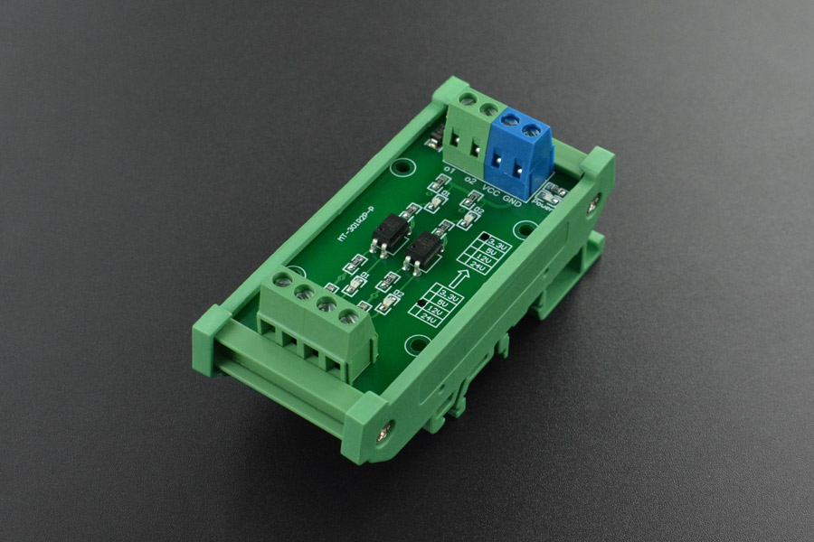
This 12V to 3.3V level converter module with 2-channel photoelectric isolation features common anode / common cathode / differential signal inputs. The level shifter translates signal level from 12V to 3.3V and offers PNP output (NPN to PNP available).
Not that specifically, but along those lines
Or you could just a BJT like a BC549
hasty solar
yeah, i have a voltage stepper with something like 12 channels, so i have a path forward. my primary obstacle now is that the headers on the stepper's board are refusing to actually lock to the headers on my wires for some reason
 sonic finch
Hi Folks,
I got a simple board made, and I've been looking at how to make it actually work. To cut a long story short, I think I've worked out why. I didn't make a grounding plain for the chip.
It looks like it need a big pad in the center of the chip.
So I'm using KiCad and went back to the schematic and connected pin 41 to my GND symbol. But the ERC fails - and this is my question:
What is the difference between a Bidirectional line ("EP") and Power Output line ?
 latent jungle
sonic finch
Hi Folks,
I got a simple board made, and I've been looking at how to make it act...
latent jungle
sonic finch
Hi Folks,
I got a simple board made, and I've been looking at how to make it act...
That’s not a failure. It is a warning. ‘Bidirectional‘ is for signal pins. So the warning is you have a power pin connected directly to a bidirectional signal pin. Which can be bad because if the pin goes low then there could be a short circuit.
sonic finch
latent jungle
That’s not a failure. It is a warning. ‘Bidirectional‘ is for signal pins. So th...
Thanks for that, the datasheet shows it as a ground pad in the center of the chip with the note:
NOTE: The exposed ground pad must be connected to a solid ground plane, as this is the ground connection for the chip.

The symbol definition shows it as pin 41, and Bidirectional, so I'll try and update the symbol, hopefully it will clear the warning.
latent jungle
It should be a Power Input
hasty solar
got my voltage stepper working, but due to the weird pin headers it came with i had to literally solder wires to the pins 💀
paper vale
Hello. Is this circuit good to control the gate of an N-channel Mosfet which will then control the luminosity of a 50W LED string with 1kHz frequency ?
 cursive sentinel
Well, you'll have quite a bit of switching loss, and the emitter resistor won't be great since you're ultimately trying to pull the base of Q2 close to ground.
 fiery parcel
Hi all,
The project I'm working on was prototyped from a Feather Rp2040. I was simply able to plug it in and launch code from mueditor. Ive juct recieved my custom PCBs for said project and id like to be able to simply plug it in and code.
I do have a segger jlink, I just dont know what software I need to flash and how.
narrow shadow
fiery parcel
Hi all,
The project I'm working on was prototyped from a Feather Rp2040. I was ...
What type of code are you trying to upload to your custom PCB? CircuitPython or C/C++?
fiery parcel
narrow shadow
What type of code are you trying to upload to your custom PCB? CircuitPython or ...
Circuitpython
narrow shadow
fiery parcel
Circuitpython
You can upload circuitpython over the USB connection to the RP2040. It presents itself as a USB drive.
fiery parcel
By holding down boot and plugging in USB? Unfortunatley not working
I have yet to try a different usb cable though
narrow shadow
You connected a USB to your cable and the USB connection on the pcb uses the USB+ and USB- pins
narrow shadow
fiery parcel
I have yet to try a different usb cable though
Use a known working data cable
fiery parcel
narrow shadow
Use a known working data cable
nothin, unfortunatley
There isnt too many indicator lights on my board, I didnt engineer it myself
narrow shadow
I would talk with the person who designed the circuit board then. See if you can get a schematic
 vast flume
Would anybody be able to help me with implementing PWM on a stm32 board? I think I am pretty close but its just not working
Heres my timer & dma configuration


And heres my clock config

This is the code I am currently trying to use:
uint32_t max_dc = 65535;
uint32_t min_dc = 0;
while (1)
{
      while(dc < max_dc)
      {
          TIM2->CCR2 = dc;
          dc += increment;
          HAL_Delay(100);
      }
      while(dc > min_dc)
      {
          TIM2->CCR2 = dc;
          dc -= increment;
          HAL_Delay(100);
      }
}
In theory it should just sweep from a 0% duty cycle to a 100% duty cycle. I previously had it running at 8mhz but now it is at 64
I'm just not sure if my current method is correct
fiery parcel
narrow shadow
I would talk with the person who designed the circuit board then. See if you can...
Is it possible it's not working because I dont have a battery connected?
narrow shadow
fiery parcel
Is it possible it's not working because I dont have a battery connected?
I don't know. How are you powering it?
fiery parcel
just USB
fiery parcel
narrow shadow
I don't know. How are you powering it?
I posted the schematics, but Im not good at reading them. Could you tell if I just need a battery?
narrow shadow
fiery parcel
just USB
What USB connector are you using? Can you send a picture of the physical hardware?
fiery parcel
narrow shadow
What USB connector are you using? Can you send a picture of the physical hardwar...
 narrow shadow
fiery parcel
narrow shadow
fiery parcel
It looks like you might need a battery
fiery parcel
I see okay. I was just under the assumption that I could power it via usb
Too bad I don’t have any batteries lmao
narrow shadow

But, it does seem like it should work from USB
Are you seeing 3.3 volts on the headers?
fiery parcel
No, those are for button connections
The charge LED lights up but other than that, nothing
 narrow shadow
Take a multimeter and probe the 3.3v and ground pins
fiery parcel
narrow shadow
Take a multimeter and probe the 3.3v and ground pins
it does look like theyre shorting
narrow shadow
fiery parcel
it does look like theyre shorting
Then something might be wrong with your circuit board.
Check on Ohms mode between 3.3v and GND without the USB cable connected.
fiery parcel
narrow shadow
Check on Ohms mode between 3.3v and GND without the USB cable connected.
3.6ohms without, 0 with
narrow shadow
fiery parcel
3.6ohms without, 0 with
You'll have to do some troubleshooting with the schematic and circuit. Unfortunately I don't have time to help you anymore.
fiery parcel
No worries
last prairie
How can I find the exact LED used in this schematic for the trinket M0. On the schematic in the downloads page it says very bright 6063, when opening up the Eagle schematic it said "CHIPLED_0603_NOOUTLINE". I am using the trinket m0 as a reference for my first PCB and I want to make sure as many of the features work first try.

 spice turtle
vast flume
Heres my timer & dma configuration
spice turtle
vast flume
Heres my timer & dma configuration
IIRC when I looked into this you need to provide a pulse value
Try this tutorial:
https://controllerstech.com/pwm-in-stm32/

PWM is a technique to control analogue circuits with digital output. It is used for generating an analogue signal using a digital source.
 crude bane
Anyone have any suggestions on driving parallel series of LEDs (LM301H EVO)? My project requires 12 LEDs to making a light array, and I'm looking for some IC to help me avoid thermal runaway for the strings.
I'm thinking maybe a LM3414, but not sure its appropriate for making a grid of LEDs.
 drowsy cove
I’m at the ideating stage for a project to make fancy earrings. They’ll have color changing LEDs on them, and a tertiary goal is to have the earrings in sync, color wise. Is there a light weight short range (8 inches?) wireless tech I could use to try and sync up the lights? I’m hoping to avoid any microcontrollers for battery life purposes, but I’m not sure how realistic that goal is
 raw otter
Can anyone help identify this IC?
 narrow shadow
raw otter
Can anyone help identify this IC?
narrow shadow
raw otter
Can anyone help identify this IC?
You could try reading the part number off of the pictures of the product
raw otter
They blurred it out
 bright thistle
raw otter
They blurred it out
bright thistle
raw otter
They blurred it out
Worse, it's laser scrubbed.
So it's either counterfeit, or somebody is trying to circumvent sanctions.
 merry folio
raw otter
Can anyone help identify this IC?
merry folio
raw otter
Can anyone help identify this IC?
Best guess: LB1848M
https://www.digikey.com/en/products/detail/onsemi/LB1848M-TE-R-E/2748224
raw otter
merry folio
Best guess: LB1848M
https://www.digikey.com/en/products/detail/onsemi/LB1848M-T...
That looks like it thank you!
bright thistle
My ¢¢, yeet the one on the board, and place a genuine one instead 🤣
raw otter
So about the same thing as whats on the A4988 driver. im trying to use an istybitsy 32u4 and the A4988 driver to run a small 5v stepper. am i using the wrong parts?
hasty solar
how would you go about cutting a linear hole into a panel or enclosure to put a slide potentiometer through it? what tool can you use to cut a precise straight line in the middle of something?
raw otter
hasty solar
how would you go about cutting a linear hole into a panel or enclosure to put a ...
Square drill on a drill press could do it

the straight part of the line would depend on your clamp setup
hasty solar
any chance i can do this for less than $100 if i want to cut plastic instead of metal or something? i don't think i have space or budget for a drill press :(
might just mount the breadboard or the pots to the exterior of the enclosure instead
raw otter
hasty solar
any chance i can do this for less than $100 if i want to cut plastic instead of ...
Easy, get your dremel, hot glue a template of your cut onto the plastic, clamp on wood guide/limiter onto an edge and work one edge at a time very carefully
You could try the cheap soldering iron with a Craft razor screwed onto the end and cut it that way, if plastic
 dry pelican
Does anyone have any idea what would make a schmitt trigger buffer IC output this and draw 200mA? My best guess is some sort of voltage spike somewhere (since this circuit is being used in a tesla coil driver). But I don't know why it would make this waveform and extra current draw until it's power cycled.
 cursive sentinel
It's possible that currents are being induced in your logic wires. Tesla coils are an extremely noisy environment.
dry pelican
Very possible
cursive sentinel
200mA is a lot for most buffers.
dry pelican
Maybe I should try shielding with some foil or just move the coil farther away
Weirdly, the buffer doesn't heat up much
cursive sentinel
Is this on a PCB?
dry pelican
Yeah
cursive sentinel
dry pelican
Weirdly, the buffer doesn't heat up much
Externally, at least.
cursive sentinel
dry pelican
Yeah
Enclosed?
dry pelican
 cursive sentinel
And U1 is your buffer?
dry pelican
U10
U1 is a PLL
I'm not sure the buffer is the one drawing the extra current, but it's most likely since it's outputting spaghet
cursive sentinel
So, you'll probably want this thing to be in a metal box. With those voltages and currents I'm surprised it functions at all.
dry pelican
Yeah the emi of this coil inverter especially is probably very harsh
cursive sentinel
Your entire PCB ground plane is probably behaving like a patch antenna as well.
dry pelican
Haven't measured it, but when probing sections of the circuit, I get random noise when running the coil
Though the probes could be acting as antennas and picking up noise or injecting noise into the circuit
I think the EMI spikes happen when the coil is rapidly detuned or isn't running at exactly its resonant freq
It's happened with other stuff
cursive sentinel
dry pelican
Though the probes could be acting as antennas and picking up noise or injecting ...
That too.
dry pelican
There might also be some currents induced by magnetic field
cursive sentinel
dry pelican
There might also be some currents induced by magnetic field
That's most likely where the 200mA is coming from.
dry pelican
It stays even after the coil is turned off though
The schmitt temporarily borks until it's power cycled
cursive sentinel
It could very easily be physically damaged.
As far as buffering is concerned, I wouldn't be using single-ended logic buffers anywhere for something like this. I'd recommend taking a look at RS-422 (or 485) buffers.
You may also want to put in some optical isolation.
Or go fully optical.
dry pelican
Better shielding and more distance is probably the simplest solution
cursive sentinel
Also, I feel obligated to mention that Tesla coils can be dangerous.
dry pelican
This one is pretty low voltage and I have experience with HV
cursive sentinel
dry pelican
Better shielding and more distance is probably the simplest solution
The issue is that you'll still have current induced in the wires going to the coil.
Well, that's good.
cursive sentinel
cursive sentinel
The issue is that you'll still have current induced in the wires going to the co...
Even with coax you're liable to see large currents going through the shield.
dry pelican
Actually U9 is the noninverting buffer
Which makes it worse since the signal out wire makes a large loop
cursive sentinel
How is that different from the inverter?
verbal crescent
hey all, is there a KiCad-compatible footprint file for the Adafruit Feather Scorpio? I haven't been able to find one.
dry pelican
cursive sentinel
How is that different from the inverter?
I meant inverter as in DC to AC power switching section
latent jungle
verbal crescent
hey all, is there a KiCad-compatible footprint file for the Adafruit Feather Sco...
All feathers have the same footprint. Even if you can't find one, it's just two 0.1inch (2.54mm) headers separated by0.8inches (20.32mm).
And KiCad already has some Feather footprints available, though, I'm not sure why the variants exist.

 rigid plume
Hi folks, not an professional in RF design, but I was wondering if my configuration would work. I'm using an RF switch to switch between an ipx and chip antenna
This is my schem, I'm using the Murata 1zm and https://www.mouser.co.uk/datasheet/2/286/CAEL_S_A0010412225_1-2559899.pdf switch


 spring moon
Am I reading the datasheet for the DS3231 correctly? It says that it has an accuracy of ±2ppm, does that mean that for every million milliseconds that pass, the clock can gain or lose up to two milliseconds?
 faint rain
spring moon
Am I reading the datasheet for the DS3231 correctly? It says that it has an accu...
faint rain
spring moon
Am I reading the datasheet for the DS3231 correctly? It says that it has an accu...
Yes. That's about 2.6 seconds a month.
latent jungle
from 0 to 40C … pretty good bet it is much lower at room temperature.
latent jungle
(or any relatively stable temperature)
spring moon
I'm planning on using it outside this winter so I'm looking at the worst case scenario
latent jungle
ah
vast flume
Hey guys, I am using the BNO085 and I cannot for the life of me figure out I2C with it https://www.ceva-dsp.com/wp-content/uploads/2019/10/BNO080_085-Datasheet.pdf
I cant find any documentation that actually explains how to use SHTP over I2C, but adafruit has an arduino library for it which uses I2C
latent jungle
I searched for ‘SHTP I2C‘ and found this PDF: https://www.digikey.co.il/htmldatasheets/production/3210489/0/0/1/sen-14686.html. It has block diagrams of the state machines for I2C and SPI. Seems like a starting point.
 latent grotto
I need help. I am trying to look at the schematic for a Esp32 S2 Dev board and on the auto program there are 2 0ohm resistors? I tried looking at the pcb but cant find them because they didnt label their resistors on the pcb. Nor can I follow the traces on a bad quality image. I need help on determining what these 0ohm resistors are.

Seems I have found a stack exchange answer https://electronics.stackexchange.com/questions/601856/why-does-esp-devkit-have-0Ω-resistors-for-the-tx-and-rx

Electrical Engineering Stack Exchange
I am trying to build my own ESP32 based PCB. I tried to copy the USB-to-serial circuit from the official DevKit. There I see two 0Ω resistors. Why did they add them? What do they do?
USB to Serial
mossy acorn
The DS3231 (RTC) has an interrupt pin that I want to connect to an interrupt pin of the ATMEGA328p. I'm looking at the typical application schematic for the IC but I'm confused what (circled in red) is? A capacitor to ground?
 distant raven
mossy acorn
The DS3231 (RTC) has an interrupt pin that I want to connect to an interrupt pin...
distant raven
mossy acorn
The DS3231 (RTC) has an interrupt pin that I want to connect to an interrupt pin...
It’s called a decoupling capacitor
Since it’s connected to Vcc, it’s going to help decouple any noise/sag in voltage to the power supply pin of the RTC
mossy acorn
I see. That makes sense now, the pin descriptions says it should be decoupled using a 0.1µF to 1.0µF capacitor
distant raven
Yup, since capacitors are cheap, you can put both to get a better overall result in decoupling
mossy acorn
alrighty will do, thank you!
mossy acorn
distant raven
Yup, since capacitors are cheap, you can put both to get a better overall result...
Should I do such filtering on other signal wires as well? For example I have a digital pin that switches a relay (currently with no filtering) that will potentially be around a lot of AC interference (HVAC systems)
Should I add those decoupling caps to those signal wires as well?
distant raven
I would follow any recommendations by the relay’s manufacturer
Sometimes they recommend bulk capacitance because turning on a relay can require a bit of current which the capacitor would help provide. But if it’s a solid state relay, that may not be necessary
mossy acorn
the signal relay datasheet doesn't have any typical application schematic or any decoupling recommendations that I can see
distant raven
If it’s a module with the relay and whatnot on a PCB it might already take care of things for you
mossy acorn
My schematic is based off https://www.adafruit.com/product/2895
A Feather board without ambition is a Feather board without FeatherWings! This is the Non-Latching Mini Relay FeatherWing. It gives you power to control, and control over power. ...
Which I see now has a 10uF decoupling cap
That I forgot to add
😄
distant raven
Ah yeah, Adafruit does a great job on adding things that should make things work good
And just a correction on my part, latching relays wouldn’t draw a lot of current or shouldn’t anyway since it would use an inductor.
mossy acorn
distant raven
Ah yeah, Adafruit does a great job on adding things that should make things work...
What about other basic digital pins? For example I have a 4 position DIP switch to serve as an "id" for each device. Should I decouple those input pins?
 distant raven
Nah, those don’t matter as much because there is usually a specific level above which a signal is considered a ‘1’ and below which is considered a ‘0’
Those wouldn’t vary enough to trigger a different input than you’re expecting
mossy acorn
So in this case since they are pulled high all should be good?
distant raven
Yup
mossy acorn
alrighty, thank you!
unreal flax
mossy acorn
What about other basic digital pins? For example I have a 4 position DIP switch ...
One thing that you might consider is using GPIO internal pullups instead of external resistors. That way you can potentially disable the pin completely when it's not being read by the software, and save the constant current consumption of the pullups, if you're low-power constrained.
mossy acorn
unreal flax
One thing that you might consider is using GPIO internal pullups instead of exte...
I actually have another question slightly relating to this. I'm using the ATmega328PB (since the ATmega328p is apparently discontinued) and I noticed all of the digital ports do indeed have internal pull-up resistors, but my question is what does the 4/7/8-bit mean for each of them?
I was thinking about the internal pull-up resistors. It could save me some money & time manually soldering the external resisters if I can omit them from the design
My main concern is if I just need to set digital HIGH/LOW, do the 4/7/8 bits really matter? Or is that more for analog stuff
unreal flax
mossy acorn
I actually have another question slightly relating to this. I'm using the ATmega...
That's just saying how many GPIO pins are in each bank. Like Port E is "4-bit" because there are only PE0, PE1, PE2, and PE3 pins, but there's no PE4, etc.
mossy acorn
unreal flax
That's just saying how many GPIO pins are in each bank. Like Port E is "4-bit" b...
I see, that's very helpful knowing this now. Thank you!
mossy acorn
unreal flax
One thing that you might consider is using GPIO internal pullups instead of exte...
So the datasheet says it has internal pull-up resistors for port E, so that means I can use them for I2C as well then? Since the I2C pins are on port E
distant raven
mossy acorn
So the datasheet says it has internal pull-up resistors for port E, so that mean...
I2C is one where you will want to use external pull ups. Internal pull ups are a bit too weak
I2C pull-ups range from 1k to 10k depending on factors like the number of i2c devices on the bus, the length of the wires for the bus, voltage of the system, etc..
mossy acorn
I see, so better safe than sorry
distant raven
Ideally stronger pull ups (less than 4.7k) are used when you have a lot of bus capacitance which can be high for reasons like having a lot of devices on the bus, and have longer wires carrying i2c. You should be okay with either 5.1k or even 10k if you only have one or two i2c devices
mossy acorn
distant raven
Ideally stronger pull ups (less than 4.7k) are used when you have a lot of bus c...
I have one I2C(RTC) and one SPI device(RFM69HCW), and I gave the SPI device quite a bit of capacitance to smooth the voltage while transmitting

Sorry it's messy lol
distant raven
All good
Yeah, 1x i2c device should be more than happy with 10k pull ups
Plus it’s an RTC, you ideally won’t be reading/writing often
mossy acorn
distant raven
All good
My thought process for this schematic was since I've used the NRF radio modules before I know it can be quite power hungry so I've been told to add a big cap. So I figured adding a lot more caps here should be good enough for this lower powered RF device(RFM69HCW)
So I added some ceramic caps for filtering and a decent sized electrolytic cap for potential power spikes to hopefully "decouple" from the rest of the circuit (aka the 3.3v regulator that powers the atmega chip and others)
Is my thought process okay?
mossy acorn
distant raven
Plus it’s an RTC, you ideally won’t be reading/writing often
I was going to use the RTC to set an alarm after a set amount of time to automatically tell the MCU (via interrupt pin) to shut off all of the relays as a safety feature. If the radio module doesn't tell the software to keep going after like an hour, the MCU will automatically shut off all relays.
cursive sentinel
As long as you can handle the current spike from those relays, it should be alright. Or better yet, don't run the relays on that supply.
mossy acorn
cursive sentinel
As long as you can handle the current spike from those relays, it should be alri...
I was planning to use a regulator that can handle 600mA, should I add another regulator dedicated for the relays? The relays only draw a few mA. My main concern is with the radio transmitter hogging all of the power while transmitting at max power for max range
I don't want a brown-out or something
cursive sentinel
They draw a few mA in steady-state. They'll draw much more when turning on, and then return that energy to the rest of the circuit when they discharge.
There's definitely a brown out risk.
mossy acorn
So how can I remedy this? More high-capacitance caps?
I have a single 100uF cap for the radio transmitter. Should I add them for each relay as well? The relays already have diodes as well
 cursive sentinel
Well, those diodes will help limit the spikes somewhat.
What is RLY_01-VIN connected to?
mossy acorn
The 600mA 3v3 regulator
cursive sentinel
And what's powering that regulator?
mossy acorn
There is currently only one regulator that powers the entire circuit. What's powering the 3v3 regulator is TBD. I'm assuming I can find at least a 3.3v 1A DC power supply. I haven't gotten that far yet
Otherwise, a 5v @ 2A power supply. Do you think that will overheat the 3.3v regulator?
That's what I'm using now with a raspberry pi zero
But I want to switch to an 8Mhz atmega328p @ 3.3v so I don't need any logic level shifters
cursive sentinel
Probably won't overheat the regulator, but I recommend not running the relays of your logic supply. Assuming you haven't purchased them yet, get ones with 5V coils and run them from the supply you're using to drive the 3.3V regulator. The current and thus power consumption of the coils will be lower.
Other than that, I would switch the '4148 for a schottky diode.
If you do already have those 3v3 relays, you can add a resistor in series with the coil to reduce the current.
mossy acorn
cursive sentinel
Probably won't overheat the regulator, but I recommend *not* running the relays ...
I'm using 3V ~50mA signal relays with a BJT transistor/diode in between. They are basically the same relays that Honeywell uses @ 3v https://www.mouser.com/ProductDetail/KEMET/EE2-3NUH-L?qs=BenOyfdfArr9l49t%252BzToQw%3D%3D&gclid=CjwKCAjwsKqoBhBPEiwALrrqiA_W6ObKodnF33jtfAH7U6J2pMFK_qdcr6kX5ubXhqy865726fu1mBoCN9AQAvD_BwE
mossy acorn
mossy acorn
The relay schematic is shown here
cursive sentinel
Ah, so they're on prebuilt modules?
mossy acorn
They are not driven directly by the GPIO pins
cursive sentinel
Yeah, I see that
mossy acorn
cursive sentinel
Ah, so they're on prebuilt modules?
No, they are a similar spec relay that I could reliably source
cursive sentinel
What I'm asking is if you have the ability to change the relay drive circuit.
 cursive sentinel
If possible I recommend sourcing a 5V relay. But as I said you can definitely add a resistor in series with the coil if you want to stick with 3V. Just use whatever resistor is needed for 50mA.
mossy acorn
cursive sentinel
If possible I recommend sourcing a 5V relay. But as I said you can definitely ad...
The relay circuit is basically a duplicate of https://www.adafruit.com/product/2895
A Feather board without ambition is a Feather board without FeatherWings! This is the Non-Latching Mini Relay FeatherWing. It gives you power to control, and control over power. ...
So you're saying since I'm potentially using 5V anyways, I should just use a 5V relay to reduce the current while switching the relays, right?
cursive sentinel
Yes, and to avoid the coil transients on your logic supply.
The 3.3V regulator (with appropriate capacitance on both the input and output) will do an excellent job of rejecting incoming transients.
mossy acorn
I see, so the MCU would potentially have less noise introduced?
cursive sentinel
Yeah
mossy acorn
And I could still switch the 5v relay with a BJT @ 3.3v
cursive sentinel
Yeah
 mossy acorn
to limit the current to whatever the required current of the 5v relay is, right?
cursive sentinel
If it's a 5V relay you don't need it. If you're sticking with the 3V relay you can still drive it with a 5V supply if you add a series resistor.
mossy acorn
ah I see, so wouldn't that just form a voltage divider?
cursive sentinel
Yep
But relay coils don't really care about the exact voltage much as long as there is sufficient current.
mossy acorn
I see, but it would still reduce the current from the 5V supply
if RLY_01-VIN = raw 5v input
is that right?
cursive sentinel
Yes, but the 5V coil will have a higher resistance than the 3V one to begin with.
And with the NPN transistor there the voltage across the coil will already be below 5V.
mossy acorn
So then should I just stick with the 3v relays with a few "smoothing" capacitors?
cursive sentinel
Nope, run 5V relays and connect them to the same supply as your 3.3V regulator. Then put 10u caps before and after the regulator.
mossy acorn
cursive sentinel
Nope, run 5V relays and connect them to the same supply as your 3.3V regulator. ...
and keep the exact same switching circuits?
cursive sentinel
Yeah
mossy acorn
even if my MCU logic is 3v3
cursive sentinel
Yep
mossy acorn
oh yeah cuz the BJT's handle that, right
cursive sentinel
 mossy acorn
I will look into this, thank you for your help
paper vale
Hello. I want to know. In three phase motor control the current flowing from the supply rail to the motor phase is positive and from the motor to the ground is negative right ?
vast flume
latent jungle
I searched for ‘SHTP I2C‘ and found this PDF: <https://www.digikey.co.il/htmldat...
I saw this as well but I'm confused with which register I should be writing to / reading from for everything
latent jungle
vast flume
I saw this as well but I'm confused with which register I should be writing to /...
Yeah, seems like they've gone out of their way to obfuscate it.
 gusty heart
paper vale
Hello. I want to know. In three phase motor control the current flowing from the...
gusty heart
paper vale
Hello. I want to know. In three phase motor control the current flowing from the...
What type of motor? Induction or Brushless?
rigid plume
Hi folks, I was wondering if someone could double check my schem part on a button to chose from different boot options for my IMX

I basically want it as BOOTMODE0 to be default to +3v3 and BOOT MODE 1 to be to +3v3 when the button is held, essentially boot mode 1 needs to be pulled up when button is pressed, and boot mode 0 while the button is pressed should go to gnd
distant raven
rigid plume
I basically want it as BOOTMODE0 to be default to +3v3 and BOOT MODE 1 to be to ...
You could probably get the same result with a different setup..
But I see what you’re trying to do
You won’t get 3.3V for boot mode 0
You’ll get some floating voltage around 2.8-3V which might be okay but I think there’s a better way to do this
Maybe an asynchronous latch
rigid plume
distant raven
You’ll get some floating voltage around 2.8-3V which might be okay but I think t...
I see, thank you.
I don't think the latch would be suitable for this
I don't think there will be any issues, but stability could be a problem
distant raven
rigid plume
I don't think there will be any issues, but stability could be a problem
This might actually work. R33 doesn’t really provide any benefits and can be removed. You probably don’t really need the diode either.
And I think you want to move the boot mode 0 signal to the other side of the pmos otherwise it will always be on regardless of the gate
rigid plume
distant raven
And I think you want to move the boot mode 0 signal to the other side of the pmo...
Thank you
rigid plume
distant raven
And I think you want to move the boot mode 0 signal to the other side of the pmo...
Are you sure? My thinking is that when the button is pressed the Bootmode0 will go to GND and the Bootmode 1 is pulled up
distant raven
The thing is the voltage divider
Remove the 100ohm resistor and you’ll be fine to keep it in place
I should have just said that, sorry
 limpid nest
What options are there for mounting a PCB to another surface at a right angle?
mossy acorn
Should I ALWAYS add discharge resistors for electrolytic caps if they're only charged to 3 - 5v? Or is that not much of an issue with such low DC voltage
They're all 100uF caps
cursive sentinel
It's not strictly necessary, but if they are after a regulator it wouldn't hurt to include a diode from the output to the input.
mossy acorn
cursive sentinel
It's not strictly necessary, but if they are after a regulator it wouldn't hurt ...
Like this?
 cursive sentinel
Yep
cursive sentinel
If the input to the regulator is suddenly disconnected, having a higher voltage stored at the output can damage it. That diode discharges the caps into the regulator if the power is removed.
Some regulators have an internal diode that does this, but not all of them.
cursive sentinel
Also, the 1N4148 is... not a great choice here. It's a signal diode. It has very fast response times and low capacitance, but it can't handle heat very well. A 1N400x would probably be better here (though admittedly overkill).
mossy acorn
cursive sentinel
Also, the 1N4148 is... not a great choice here. It's a signal diode. It has very...
Oh yeah, thank you for reminding me. I just copied a diode from another part of the schematic and pasted it there just for the screenshot
Immediately forgot to ask what a good choice would be lol
The diode is in the right direction though, right? I want the current to flow from VOUT to VIN
cursive sentinel
Correct.
mossy acorn
cursive sentinel
Correct.
What would be an ideal Average Rectified Current for picking a diode? I'm trying to find a suitable SMD version. Should I choose 600mA since the regulator is 600mA?
Actually that gave basically zero results on LCSC
distant raven
cursive sentinel
It's not strictly necessary, but if they are after a regulator it wouldn't hurt ...
Most regulators have a diode that does this
mossy acorn
I'll check the datasheet
distant raven
Is there any benefit to adding an external one?
As for rectifying/protection diodes, generally keeping it around what your regulator(s) can supply is a good idea
You’d search Schottky diodes
mossy acorn
The AP2112 includes an auto discharge
function which connects the output to ground via 60 of resistance
when the device is disabled.
when the device is disabled I'm assuming that includes when it isn't receiving any power?
distant raven
I’d imagine that implies there is an output enable pin
distant raven
Then it won’t be disabled unless vin is disconnected
You can tie Enable to a switch if you want
mossy acorn
I want the device to be powered always when plugged in to a power source, so it should discharge fine without the external diode?
cursive sentinel
mossy acorn
What would be an ideal Average Rectified Current for picking a diode? I'm trying...
So, it's just a protection diode. It will only be forward biased when/if power is disconnected. It will conduct a significant current initially, but as the capacitors discharge the difference in voltage between the input and output will drop rapidly. It's possible to calculate the total energy stored in the capacitors at a given voltage (3.3V in your case) and choose a diode capable of absorbing at least that much, but I don't think it's really necessary in this case.
mossy acorn
cursive sentinel
So, it's just a protection diode. It will only be forward biased when/if power i...
So if I can find the SMD equivalent of a 1N4001, just slap it on there and I should be good?
mossy acorn
cursive sentinel
Schottky is fine as well.
Would this be okay? https://www.lcsc.com/product-detail/Schottky-Barrier-Diodes-SBD_Jiangsu-Changjing-Electronics-Technology-Co-Ltd-B5819WS_C22624.html
B5819WS Jiangsu Changjing Electronics Technology Co., Ltd. US$0.0275 - 40V 600mV@1A 1A SOD-323 Schottky Barrier Diodes (SBD) ROHS datasheet, price, inventory C22624
cursive sentinel
Perfect.
mossy acorn
Awesome. Thank you!
 marsh rain
On a 2-layer PCB, is filling empty space with a +5V pour and GND pour on either side a good idea? Like this specifically:

 cursive sentinel
It's fine, though generally you want to avoid large divisions in the planes.
marsh rain
cursive sentinel
It's fine, though generally you want to avoid large divisions in the planes.
Ah ok, for this one then, I may remove the GND pour (top layer) and just route individually. Do you have any other advice or criticism for my routing? This is my first time designing anything more than a breakout board.
cursive sentinel
marsh rain
Ah ok, for this one then, I may remove the GND pour (top layer) and just route i...
The ground pour is the one you should keep. I would move it to the bottom and route the 5V rail separately.
marsh rain
Ok, will do, thank you for the help
paper vale
gusty heart
What type of motor? Induction or Brushless?
brushless
 summer sigil
Not sure where to ask this, so i try here:
i have a ESP32-S2 from adafruit, but there are two revisions; B & C sold. How can i tell which one i have?
(i want to turn off I2C during deep sleep and you do the opposite depending on revisions, see picture.)
Also: does the "turning off" actually work in deep sleep if i just set it to the inverse before going to sleep. My LED on the I2C device is very dimly on during DS.

 grand fossil
Revision C has an AP2112 in place of the mosfet for i2c power control.

That highlighted component is the AP2112
I think the pinout photo above is of the revision B since it looks to have a mosfet there.
For the two revisions (left is the C right B) schematics of this change (it's tied to the enable pin of the AP2112 to hande the i2c power control for the revision C).

 latent jungle
(I deleted my messages on the I2C question. I don't think they're helping. I'm utterly confused by the documentation.)
vast flume
latent jungle
Yeah, seems like they've gone out of their way to obfuscate it.
Yeah its actually so crazy
vast flume
latent jungle
(I deleted my messages on the I2C question. I don't think they're helping. I'm u...
Was that to me or someone else?
latent jungle
vast flume
Was that to me or someone else?
to Axel regarding the ESP32-S2 Feather's I2C power control.
latent jungle
vast flume
Ah
for yours, there must be another PDF somewhere with more detail.
supple pollen
I'm guessing power is flowing through the I2C pull-up resistors, to the I2C clock/data leads, through the protection diodes of the target onto the target's power supply bus, and hence to its LED.
latent jungle
That's why I find it strange the documentation for the I2C_Power says the example code disables the pull-ups, but doesn't. I'm clearly missing something.
grand fossil
Revision C has the I2C pullup on the output from the regulator while revision B has it from 3v3 directly so likely he has the revision B and is experiencing what madbodger is describing I think. Wondering if the example was updated in the past when the board was updated to source the regulator for the pull ups as it would be true in that case (just not for folks with the earlier revision)?


 astral sun
I got a 4-rotary neo Pcb and the 100 step from www. When I plug it into my macro key - no worky seems like a current draw exceed (without message) or short as there is no boot “green”
Any obvious answer to connect the two?
I used the big AB vcc gnd and vcc I just took off the rotary-pcb
supple pollen
I'm trying to figure out what that last sentence means. It almost looks like you hooked power and ground to A and B?
astral sun
Hooked power (vcc) and ground and used the larger A B terminals for the rotary inputs @supple pollen
latent jungle
grand fossil
Revision C has the I2C pullup on the output from the regulator while revision B ...
I'll be up front. It's a poorly written example for multiple reasons. I think it makes the most sense to disable the "power" (for either version) and then switch the I2C pins to INPUT so they are disconnected as well. (Which was the source of my initial confusion--that's how I would do it.)
but that's not what the examples show
 inner rampart
This is so weird. The board claims to be feather form factor but the pins are staggered and the included pin headers don't fit through the holes.

oh wait . from the website "Staggered rows of holes are used to allow for solder-less connection to header pins which is convenient."
but what's the point? so that it rides on top of pins or something
oh I guess you just shove them in and they stay ? bizarre.
 vestal lake
Yep, that's a really simple way to mimic stuff like sockets while not needing hardware
I've seen it used a fair bit for keyboards, and my experience is it mostly works
tough matrix
inner rampart
but what's the point? so that it rides on top of pins or something
indeed, you just force the headers in and the friction holds them in place.
It works ok for temporary connections, when testing things
latent jungle
Years ago, Adafruit had a “lock” footprint in their Eagle library like that layout. It was to hold headers in place while you solder them.
drowsy cove
inner rampart
oh I guess you just shove them in and they stay ? bizarre.
Right. It’s a way for people new to this to get to experiment with electronics without having to solder, which is a decent sized hurdle for some people to get over
inner rampart
The real hurdle is getting the crappy example code to compile for this board.
summer sigil
supple pollen
I'm guessing power is flowing through the I2C pull-up resistors, to the I2C cloc...
yes, thats what i suspect as well, thus it would be Rev B i have. And they solved it by doing pull down instead and tying SDA and SCL to VSENSOR?
summer sigil
grand fossil
Revision C has the I2C pullup on the output from the regulator while revision B ...
yes! thanx. so thats a way to tell which revision you have. if the led is slightly on, you have Rev B.
summer sigil
latent jungle
I'll be up front. It's a poorly written example for multiple reasons. I think it...
so, now that we know i have Rev B, whats the correct code?
for switching it on, then in the end, before deep sleep (set it to INPUT??) and set it to a state with digitalwrite.? for least current consumption i mean.
is there something one can do with
esp_sleep_pd_config(...)
it doesnt help that it says both rev b and rev c in this picture:

 viscid coral
Hi, folks. I'm having trouble with EAGLE's layer setup. I would like a 4-layer board (signal, ground, power, signal) with blind vias between each outer layer and inner layer (1:2, 1:15, 2:16, 15:16). I don't need buried vias. I'm getting confused with this setup string and the little tool to the right is not helping either. Any assistance would be appreciated. Thank you.
 viscid coral
Actually, I think I got it. Took some guessing and checking
([2:[15:1+2*15+16:2]:15])
Not entirely sure what the rationale is behind such a system. Thought I found a forum post on why the setup is the way it is, but I can't find it now.
rigid plume
Hi everybody, I was wondering if someone could skim thru my schem for a simple halloween light with speakers. Just need to confirm everything looks fine between connections to the esp32 s3 module. Thanks
rigid plume
 supple pollen
You probably want to have different signals for each LED's data in and data out. 3.3V is marginal for those LEDs, you might want to power them from VCC instead. You don't want to connect the SDO pin of your BME680 to ground, you can just leave it open if you don't care about the return data. For your audio amplifiers, you probably want to tie SD_LEFT to 3V3, and SD_RIGHT to 3V3 via your 200k resistor.
rigid plume
supple pollen
You probably want to have different signals for each LED's data in and data out....
The BME680 datasheet says to connect to GND to select an i2C address, I saw some references that said to just tie them together with an 200K resistor using an calculation.
Thanks
 coarse lark
i have a question regarding mounting holes on a pcb, should they be grounded for safety and noise interference reasons?
 timid parrot
How cool to see that in the wild, though I'm sorry it's not working for your application!
 glacial gale
Is there something like a general-purpose ALU that can support arithmetic operations on arbitrary bit-widths?
it can support 32-bit, 128-bit, and more. But doesnt take up that much space or for bigger bit widths, can still execute in a reasonable amount of time by maybe some special cache designs and feedback loops
latent jungle
coarse lark
i have a question regarding mounting holes on a pcb, should they be grounded for...
If you want the metal enclosure to act as (part of) an EMI shield, then yes.
left grove
(whatever you do, please don't connect 3 holes to GND and the fourth one to VCC and then advertise the board for a use case that involves mounting it with metal screws to a carbon fiber sheet😂)
supple pollen
glacial gale
Is there something like a general-purpose ALU that can support arithmetic operat...
I'm thinking of 74181 and AMD2901 but those are both old technology
glacial gale
oh did they have support or acceleration for arbitrary bit widths?
supple pollen
They both support arbitrary bit widths
 plucky citrus
does featherwing 2895 come with the 12 pin and 16 pin header? i see headers in the picture but they are both 16 pin. description says "we include header you can use to attach" but im not clear on if i need to order something separate
left grove
you can just cut pin headers with side cutters or just break them apart
plucky citrus
so its 2x 16 pins that come with it?
 left grove
looks like it to me, but I'm not adafruit so I can't say for 100% sure
see those lines?
 plucky citrus
yes those are the break points?
left grove
exactly
plucky citrus
thanks
left grove
np. 😄 But it really doesn't hurt to buy some pin headers anyway. They're a great thing to have on hand
 trail tartan
Hey! I am trying to connect myoware 2.0 (https://myoware.com/wp-content/uploads/2022/03/MyoWare_v2_QuickStartGuide.pdf) to Adafruit Feather V2 (https://github.com/adafruit/Adafruit-ESP32-Feather-V2-PCB/blob/main/Adafruit ESP32 Feather V2 Pinout.pdf). The original guide for Myoware says that the following 3 connections are needed:
GND
VIN
ENV
I am a noob and trying to figure out how many myowares could I connect to one feather v2. Any help would be greatly appreciated.
latent jungle
trail tartan
Hey! I am trying to connect myoware 2.0 (https://myoware.com/wp-content/uploads/...
It says the connect ENV to an analog input. That feather has 6 pins named Ax and additional 8 pins that can also be used as analog. So 14 analog inputs. Depending on how fast you need to read the sensor, you can probably connect up to 14.
trail tartan
latent jungle
It says the connect ENV to an analog input. That feather has 6 pins named Ax and...
Thank you so much. As for the GND and VIN. Can I connect multiple sensors to the same GND and VIN on the feather?
trail tartan
latent jungle
Yes.
Thank you so much James. 🙂
fickle patio
Hello friends 🙂 When powering a bare Pi Pico W with 2.6v to the VSYS pin, my meter is showing 1v on the VBUS pin. I was expecting VBUS to be at 0v when not connected to USB. Can anyone explain why?
latent jungle
fickle patio
Hello friends 🙂 When powering a bare Pi Pico W with 2.6v to the VSYS pin, my me...
It's probably a bit of voltage leaking through U2+L1. When D1 is reversed, a tiny bit of leakage current gets through. It's enough to develop a voltage across that voltage divider.


Diodes aren't as perfect as we pretend them to be.
fickle patio
latent jungle
It's probably a bit of voltage leaking through U2+L1. When D1 is reversed, a tin...
Thank you!
supple pollen
While Schottky diodes like that one are useful for fast switching and low forward voltage drop, they generally do leak a little when reverse biased.
cursive sentinel
They also tend to have higher capacitance and can only handle up to ~30V reverse biased.
So they're very good in (asynchronous) switching regulators.
distant raven
cursive sentinel
They also tend to have higher capacitance and can only handle up to ~30V reverse...
There’s a handful of decent Schottky diodes that are good up to 60V+
This one is a favorite of mine for handling higher DC inputs into a 5V/5A switching regulator
ocean coyote
Hello, Im looking to have a way to switch a usb device on and off without needing to unplug, this is not just for power i want to have the device restart as if it was unplugged and reconnected because im using to to log traffic.
by the looks of this cable, its using a SPST switch so might only be doing the 5v line?
does this have an effect on the the device / cause any back feeding issues as id imagine the host could still send data until something times out
https://www.amazon.com.au/Cable-Matters-Extension-Switch-Support/dp/B08M45QM3J?ref_=ast_sto_dp

Cable Matters USB 3.0 Extension Cable with On Off Switch 6 ft, Support Data and Power (USB 3.0 On Off Switch/USB On Off Switch)
p.s had an email returned saying it does only switch 5v
tough matrix
id look at USB switchers like this one: https://a.co/d/0u0yhgX
As far as I understand, these switch both power and data lines.

USB Switch 3.0 KVM Switch,Bi-Directional USB Switch Selector 2 in 1 Out/1 in 2 Out, Viagkiki USB Switcher 2 Computers Share 1 USB Devices for PCs Mouse Keyboard Printer Scanner (with 2 USB 3.0 Cables)
tough matrix
I have a question of my own.
I need to prevent shorts from accidental contact of tails of headers and other THT parts on the back side of the board with some metal parts which will be very close to the board.
My plan is to cut the tails flush with surface and then cover with insulating varnish/conformal coating.
Anyone has experience with such coatings? Can I just use clear nail polish, as is suggested in some sources, or I should really use specialized coating?
left grove
I feel like conformal coating/nail polish might rub off on sharp edges (like protruding pins if the board slides/vibrates around)
ornate sleet
close enough where you can't just fit a thin(ish) film of flexible+insulating material in the middle?
...or sharp edges that may poke thru it?
worldly schooner
tough matrix
I have a question of my own.
I need to prevent shorts from accidental contact ...
For a temporary fix, nail polish will do fine, but it doesn’t last nearly as long as a proper conformal coating.
Assuming low-voltage signals, anyways.
tough matrix
certain, we are talking 5v max
tough matrix
ornate sleet
close enough where you can't just fit a thin(ish) film of flexible+insulating ma...
I can.
but I am worried it might start peeling off in the long run...
supple pollen
Nail polish works well. You can also use epoxy, hot glue, polyimide tape, etc. (vinyl tape isn't good for this as it's too soft)
worldly schooner
If you’re only worried about shorts, even some plastic spacers should do the trick.
 unique patio
tough matrix
I have a question of my own.
I need to prevent shorts from accidental contact ...
unique patio
tough matrix
I have a question of my own.
I need to prevent shorts from accidental contact ...
Kapton tape or a piece of sheet polystyrene (from a hobby shop) could work
spacers are good too, and simple, if you have to mount the board with screws anyway
 keen idol
Old fashioned fishpaper is the perfect thing for this, and it's very retro. I think Digikey still carries it.
rigid plume
Hi folks I wanted to ask for your opinions on this, is it fine for me to place an SDRAM IC under the USB C port on my RT1170 IMX board, will there be significant EMI issues? I'll make sure routing is good aswell as reference gnd layers
 latent jungle
It is much less of a concern if you're using a 4+ layer board.
 pure matrix
How can I add https://github.com/adafruit/Adafruit-KB2040-PCB to Kicad 7?

GitHub
EagleCAD PCB files for Adafruit KB2040. Contribute to adafruit/Adafruit-KB2040-PCB development by creating an account on GitHub.
latent jungle
pure matrix
How can I add https://github.com/adafruit/Adafruit-KB2040-PCB to Kicad 7?
Version 7 lets you import the schematic. Future versions might let you import the PCB as well.
Unfortunately, despite claiming to be an “Open Source” hardware company, the ONE area that Adafruit refuses to support open source work is in EDA.
tough matrix
For the first time in my life, the PCB manufacturer asked me to confirm polarity of a power inductor I had on my board. I thought they got something wrong - never knew inductors have polarity - but indeed, googling brings up this FAQ:
https://industrial.panasonic.com/ww/faq/faq0117
(and a more detailed app note from Murata: https://article.murata.com/en-global/article/basic-facts-about-inductors-lesson-6).
Though in my situation, it doesn't' really matter...
tough matrix
latent jungle
Unfortunately, despite claiming to be an “Open Source” hardware company, the ONE...
AFAIK, KiCad 7 can import both schematics and board files from Eagle?
https://community.element14.com/technologies/open-source-hardware/b/blog/posts/working-with-kicad-7-importing-eagle-files

element14 Community
Table of ContentsIntroductionImporting the projectEnabling Schematic and PCB UpdatesResolving PCB ProblemsZones (Copper planes)Rule Areas (Keepout regions)Component FootprintsResolving Schematic ProblemsText SizesDrawing FrameSummaryIntroductionHaving used EAGLE CAD for several years, I had a set o
latent jungle
tough matrix
AFAIK, KiCad 7 can import both schematics and board files from Eagle?
https://co...
Cool to know. In the KiCon 2023 presentations there was an overview of upcoming changes to the importers. My only takeaway was v7 had a lot of schematic import capability already (with library and PCB files lagging across EDA tools.)
tough matrix
yeah, at the moment PCB import requires some manual adjsutments, it is a pain...
ocean coyote
The peripheral has the potential to reach 0.42A (thats the most ive seen it draw with all leds white)
is there a way to keep using bus power but increase current somehow

because the project already consumes 0.09A for the lcd backlight
and there will be wifi and bluetooth eventually
https://www.adafruit.com/product/4654
is that what this is for? or is that when the battery is connected https://www.adafruit.com/product/5723
 uncut basin
Hi all, quick (and probably dumb) question regarding Neopixels:
My QT PY ESP32-S2 runs off 3.3V, but the Neopixels require 5V. Do I need a logic level shifter to 5V to be able to drive the Neopixels?
The documentation says it's better. But come to think of it, there is a neopixel LED on board that works just fine. So am I better off powering the Neopixels with 3.3V instead of 5?
worldly schooner
ocean coyote
The peripheral has the potential to reach 0.42A (thats the most ive seen it draw...
Unfortunately, the Pico doesn’t have any power negotiation capabilities, so 500mA is the limit it can draw according to usb specifications.
The bus power is limited to 5v 500mA, but it could be possible to use a separate source for more continuous current.
If it were just a Wi-Fi component drawing small bursts of current, you could get away with a suitably sized capacitor, but for an lcd backlight you’re probably going to need an external source of power.
worldly schooner
uncut basin
Hi all, quick (and probably dumb) question regarding Neopixels:
My QT PY ESP32-S...
The sk6812 variety is capable of 3.3v power, and that’s what the board neopixels usually use. With the older ws2812 variety, 3.3v can be very hit-or-miss, so a https://www.adafruit.com/product/5645 is highly recommended.
Our QT Py boards are a great way to make very small microcontroller projects that pack a ton of power - and now we have a way for you to quickly add a strand of NeoPixels with a 5V level ...
Lower voltages also have lower efficiency over longer runs, so for a proper LED strip, you probably should use proper power. For onboard neopixels, however, you should have no problem using it as built.
uncut basin
Thank you @worldly schooner ! In reality, it's just a ring with 8 Neopixels on it
The BFF looks perfect, but this ruins my hardware design 😄
tough matrix
uncut basin
The documentation says it's better. But come to think of it, there is a neopixel...
I usually power NeoPixels (ws2812 or sk6812) directly from a 1-cell lipo, works like a charm.
But if this is not an option, then yes, 3.3v should work too with sk6812
trail tartan
Is it possible to run a machine learning model on the feather v2? Are there any examples of it?
latent jungle
trail tartan
Is it possible to run a machine learning model on the feather v2? Are there any ...
ESP32 v2? You can probably run TinyML on it.
tough matrix
the easiest way to create and run a ML model on an MCU is using Edge Impulse - platform that makes trainign and deploying ML models as easy as point-and-click. They do offer support for ESP32-based boards (but not Feather - you would need to make some modifications): https://docs.edgeimpulse.com/docs/development-platforms/officially-supported-mcu-targets/espressif-esp32
 trail tartan
latent jungle
ESP32 v2? You can probably run TinyML on it.
trail tartan
latent jungle
ESP32 v2? You can probably run TinyML on it.
Thank you. Will give it a shot and report back.
latent jungle
@trail tartan I would take @tough matrix advice and also look at Edge Impulse.
depending on what you mean by "run a ML", it can significantly help
 fervent lance
I want to place a number of the Adafruit htu21d-f around my house but I need an enclosure. Is there such a box or a 3D printer file for a box available?
 jade wedge
I'm trying to plot out a project using SPI and the ATTiny. During reset all the IO pins on the Tiny go Tri-state, which I understand means high impedance or basically an input. Will that cause any of the SPI slave devices to think they're being communicated with, or am I going to have to put a pullup resistor in to ensure that the line stays high?
 lime herald
fervent lance
I want to place a number of the Adafruit htu21d-f around my house but I need an...
lime herald
fervent lance
I want to place a number of the Adafruit htu21d-f around my house but I need an...
That's just a sensor - you'll need to connect it to a CPU board like one of the feathers to use it. So you'll need an enclosure for all of that, and the particulars would depend on the board you're using.
Once you have that settled, there's a very cool project called "Easy Enclosure" that you can use to specify what you need in an enclosure and generate STL files that you can then use to print.
Easy Enclosure is an open-source 3D modeling software tailored specifically for designing 3D-printable enclosures. It aims to provide an intuitive interface and a set of user-friendly controls that allow even those with little or no 3D modeling experience to create custom enclosures for their electronic projects, prototypes, or DIY gadgets.
jade wedge
Oh, I should point out the reason I'm concerned about this is I'm hoping to use ISP programming, which uses the same pins as SPI.
fervent lance
I am using an ESP8288 and ESPhome to monitor the temperatures. If there is a box just for the sensor, I could hide 8288 and the PS close by and run the wires to the box. I will check out Easy Enclosure. My neighbour has three 3D printers and he really wants some projects. Thanks for the tip.
latent jungle
jade wedge
I'm trying to plot out a project using SPI and the ATTiny. During reset all the...
you would only need to use a pull-up on their chip select lines to prevent them from being accidently enabled
jade wedge
Right, I just don't know if the Tiny's pins being high impedance could potentially cause them to be enabled since it's not strictly floating. At least, I don't think it is. I guess ultimately adding them wouldn't hurt. Especially since I hope to have this board actually fully assembled.
latent jungle
If you use a pull-up resistor on the chip select line, it will prevent them from being accidently enabled.
That's the point of a pull-up (or pull-down). To pull the pull the pin to a known state when it's connected to a high-impedance.
jade wedge
Ah. I figured it was more when the pin could be floating.
I assume 10k should be fine? That's what I tend to see everywhere else.
jade wedge
Cool. Time for more board design. Well, tomorrow.
thin falcon
I have a feather project where I want to be able to power the feather from USB when it is plugged in. When USB is not connected, I would like to power the feather from a DC power supply of +5V on the Feather's USB pin. Normal operation is the DC power supply and no USB connection. We need the DC power supply to power some motors. DC in is actually 12V for the motors and I have a voltage regulator which also converts that DC to 5V for the feather.
SO, right now, I have a toggle switch. It either connects this +5V to the feather's USB pin or disconnects that
I would like to eliminate that toggle switch. I think the user will forget to switch it. How about a relay or some such instead of the manual switch. For this, I would need some signal that USB was either plugged in or not. What signal on the feather could tell me this?
bed time for me. I'll check back tomorrow to see if anyone has thoughts on this.
vestal lake
In theory you could just get away with a diode between Vusb and Vin so you're not backflowing the 5V up the USB line. Iiirc at least a few boards do this already so you can have it externally powered and still have USB connected for debugging
unique patio
thin falcon
I have a feather project where I want to be able to power the feather from USB w...
Discussion here: https://learn.adafruit.com/adafruit-feather-m0-express-designed-for-circuit-python-circuitpython/power-management-2#alternative-power-options-3122391. May not be what you want to hear.
The QT Py boards have a diode on them to prevent backpowering the USB port when supplying external 5V. But I don't know if those boards have enough pins for you.
You could add an external diode on the USB 5V line to prevent backpowering. So you'd add an external USB socket, pass through the data and ground lines, and pass 5V from the external socket to the USB power line. You will also want a diode preventing backpowering your external 5v regulator.
thin falcon
unique patio
You could add an external diode on the USB 5V line to prevent backpowering. So y...
Perhaps I could disable the onboard regulator. Then supply the board with my own LDO. The input to the LDO would be switched via a relay. The VBUS pin would drive the relay's coil. The NC relay pole would be connected to my external +5VDC. The NO is connected to the VBUS pin. So, when the USB is not connected, the board is powered from my external +5VDC via my LDO. When USB is connected, VBUS will be +5V, the relay will energize, USB +5V will be connected to the LDO and drive the board. What do you think? See attached schematic.
 unique patio
thin falcon
Perhaps I could disable the onboard regulator. Then supply the board with my own...
unique patio
thin falcon
Perhaps I could disable the onboard regulator. Then supply the board with my own...
I don't know if the LD33 will object to being backpowered. The diodes suggested above accomplish the same switching electrically. You can use low-dropout diodes, but you need to choose diodes that are rated for enough current.
thin falcon
since I tied the "EN" pin to ground, I thought that the LDO wouldn't get back powered
latent jungle
depends on the regulator. some of them connect their output to ground through a resistor when disabled. (often those call it a shutdown pin instead of enable.)
thin falcon
output to ground when disabled is fine. The 'EN' pin I meant is on the feather - it should shut down the regulator on the feather, not my external LDO. I hope you can see my drawing I posted above
OK, I see. If the LDO on the feather did that short to ground behavior, This wouldn't work
latent jungle
output to ground when disabled is fine
Okay, but I gave that as an example. You need to verify what the actual behavior is.
The regulators that support it do not "short" to ground. They connect through a resistor. The intention is to bleed off the output capacitors safely.
thin falcon
latent jungle
> output to ground when disabled is fine
Okay, but I gave that as an example. Yo...
Yes, for sure. Time for the multi-meter. Thanks much. I will report back.
 grim surge
I'm wanting to build an 'optionally wireless' keyboard. I also want to integrate a USB 3 hub.
I'm just getting started on all of this with no bg in electronics so I figured it'd be easier to cobble together pieces.
Basically take a slim hub like this one:
https://www.aliexpress.com/item/1005006085112684.html?
And take it apart to harvest the PCB that way I have plenty of power for LEDs/charging the batteries available.
- Connect one port internally to my keyboard PCB
- Connect one port internally to a battery charger/use it to power the (5v) LEDs
- Expose 2 ports externally for use with other devices (when plugged in obviously)
However I'm struggling with figuring out the second point there. Initially I thought of using a powerbank PCB figuring they'd be able to take in power and put it out at the same time but can't really find any board that says it can and the one I got and tested drops the output current very low when it's being charged. Then going by some internet wisdom ( https://www.studiopieters.nl/battery-charger/ ) the way to do it seems to be using one of these:
https://www.aliexpress.com/item/32779467674.html
However I'd like to have a bit more than 1A available to play with as it's probably going to have to power 150 or so LEDs (plus 2 screens and an ESP32-S3).
I found this on my own which might be the best option?
https://www.aliexpress.com/item/1005002982442200.html
The PCB however is pretty big as its intended purpose seems to be to fit 2 18650 batteries.
Is there a better / smaller solution, is there something wrong with my approach?
ChatGPT sadly was quite useless for advice on this
trail tartan
latent jungle
<@842597496219369472> I would take <@320665963886280706> advice and also look at...
I took a look at it. It seems impressive but is it completely open-source? I am hesitant to invest in a system that is not fully transparent.
tough matrix
trail tartan
I took a look at it. It seems impressive but is it completely open-source? I am ...
no, edge impulse is not open source, unfortunately
 dark skiff
grim surge
I'm wanting to build an 'optionally wireless' keyboard. I also want to integrate...
dark skiff
grim surge
I'm wanting to build an 'optionally wireless' keyboard. I also want to integrate...
You don't have to connect everything to USB. It will be much easier to use the TP4056 charger and a step-up system that will meet the current requirements.
Powering it from USB may be a bit more of a challenge, so as to automatically disconnect the battery. Because you would have to implement this circuit: https://electronics.stackexchange.com/questions/530237/automatic-power-selection-circuit-design-and-part-selection

Electrical Engineering Stack Exchange
I am working on a project that has LIPO battery and a USB as a power inputs. The system should use the battery but if the USB cable is plugged it has to use that as a power source instead of the ba...
grim surge
dark skiff
You don't have to connect everything to USB. It will be much easier to use the T...
I'd rather have USB as that's easily available (got chargers arounds and they're multipurpose so there's always a backup, and I want a USB hub in it anyway - might as well make it a powered one - might come in handy for connecting higher power devices at some point)
Also, from what I understood is that tp4056 is problematic because of this bit:
By default, most boards with the TP4056 are programmed for a charging current of 1 Ampere. It can be changed by changing a resistor. This means that until there is a consumption less than 100mA, the charging process will not be interrupted! Since we have connected an extra circuit, the charger will never stop charging the battery due to that extra consumption. If the TP4056 programmed for a charging current of 500 Millie Ampere. Then that means until there is a consumption less than 50mA, the charging process will not be interrupted!
And that's why the MCP73871 based board is preferred.
I should have probably mentioned the entire setup though.
It's a BPI-Leaf-S3 board (so it already has a LIPO connector) which I assume I can hook up straight to the batteries (possibly with a Diode so it just draws power rather than try to charge whilst the UPS is already charging?) and it powers:
- 2 screens
- 7 or 8x CD74HC4067 for the keyboard
- Bunch of pins pulled to high for detecting keypresses
Then I'd use that 5v UPS board to:
- Charge the batteries
- Power the LEDS (number to be determined yet, but ~110 for keys + some amount for underglow)
That way I think I have my bases covered? I was mostly just wondering if there's something like the UPS board but not so obviously designed for 2x 18650 batteries as the 18mm is a bit thick going by initial design drafts. I was thinking something more along the lines of 2 * 10000mah or 6 * 3000mah batteries (not entirely sure yet if 2 * 10000 fits without making everything rather thick)
trail tartan
tough matrix
no, edge impulse is not open source, unfortunately
Thanks. Will figure out an alternative then.
dark skiff
grim surge
I'd rather have USB as that's easily available (got chargers arounds and they're...
I'm too stingy to use this USB-UPS system, but if you want, no one will stop you. You can choose the version without a basket and solder any cells. I saw a diagram of this board somewhere, but as usual I can't find it XD. Search the comments on Aliexpress, maybe someone wrote what kind of systems were used.
https://4.bp.blogspot.com/-C7If63_JEC4/VmwsFUeYUrI/AAAAAAAADX4/MgG3satnQ7I/s1600/Arduino%2BUPS.png
Using the circuit from the link/picture, the battery power is disconnected when the USB is connected. I haven't checked the schematic of the board you want to use, but it probably uses a similar solution. You just need to check whether the diode and mosfet can withstand the load. Maybe this circuit - with two diodes - will be more understandable. (but if you use the right mosfet, you won't have losses caused by the voltage drop on the diode - 0.5V. And smarter people than us came up with that solution)
BTW: What kind of diodes do you choose that will be 5V? If you increase the voltage, it may be better to use a higher voltage.
And what kind of power-hungry device are you planning to connect? Because when it comes to power-hungry receivers, the only thing that comes to mind is a smartphone, and these would like PD and more than 5V.


and this part looks as "automatic power selection"
 grim surge
dark skiff
I'm too stingy to use this USB-UPS system, but if you want, no one will stop you...
grim surge
dark skiff
I'm too stingy to use this USB-UPS system, but if you want, no one will stop you...
You can choose the version without a basket and solder any cells
Yeah that's what I figured would be worth a shot.
And what kind of power-hungry device are you planning to connect? Because when it comes to power-hungry receivers
Can't really think of anything that draws more than an external hard disk at the moment, but who knows what I'll be using in 5 years (hoping the keyboard lasts a long time).
BTW: What kind of diodes do you choose that will be 5V?
HD108 https://www.aliexpress.com/item/1005002646165218.html - supposedly they have better low brightness performance than most, they're nearly the same price as APA102 and the slightly higher additional price is offset by not needing a level shifter as they'll happily take 3.3V logic . From what I've read they seem to be basically APA102 but better in a lot of ways.
Thank you :)!
dark skiff
grim surge
> You can choose the version without a basket and solder any cells
Yeah that's w...
There's something wrong with the power of these LEDs. From the data on the Aliexpress it can be calculated that 100 x HD108 = 8.5W. And in the datasheet from the Internet it is 20W... https://www.rose-lighting.com/wp-content/uploads/sites/53/2019/11/HD108-led.pdf
And this hub... Only the 5-port hub has 1 PD 100W port. So I wonder if there are computers that have PD-out. (The standard scenario is to connect the USB hub into the PD power cable.)
grim surge
dark skiff
There's something wrong with the power of these LEDs. From the data on the Aliex...
Don't think there's PCs that do much current (maybe those with the newer thunderbolt / USB 4 ports?)
It'll be connected a ASUS B450 ROG Strix Gaming F motherboard though. Which at best tops out at 900ma from what I could find.
So I was indeed thinking a second power adapter for the hub, don't think I'll need to run the LEDs at anywhere near full brightness, part of why these seem especially attractive as their low brightness performance is supposed to be very good.
There's a more current version of the datasheet btw https://www.rose-lighting.com/wp-content/uploads/sites/53/2022/07/HD108-Specificaion-V1.2.pdf
I'm guessing the Aliexpress data might be more accurate, the sheet does state the typical power draw is 17mA, 20mA max.
20mA * 100 LEDs = 2000 mA = 2A
2A * 5V = 10W
17mA * 100 LEds = 1700 mA = 1.7A
1.7A * 5v = 8.5W
^^^^^^^^ That lines up exactly with the aliexpress data you mentioned.
Not sure why the older pdf mentions a power draw of 0.2W that just seems to be flat out incorrect - and it's removed from the newer one.
 woven bluff
is BLE suitable for short-range remote control?
 crude ocean
I would naively presume so
nominal max range <100 meters (I would presume much shorter, but that is still plenty for a short range remote)
woven bluff
security is the problem, I cannot find any reference for enabling level 4 security on most embedded systems.
crude ocean
maybe that is part of a more advanced software stack?
supple pollen
I agree: the transport itself is just a pipe, if you want security, the usual approach is to layer it on top (the same as is done with TCP/IP: if you want a secure link, you can use a VPN or SSL or some such). While secure radio link products do exist, they tend to be specialty products that can be difficult to integrate and debug.
woven bluff
well, the security of the pipe does matter, otherwise TLS won't be developed
 low anchor
For the MCP4728, I'm looking at the datasheet and wondering if I can leave the LDAC pin floating except when used to update the address (so I can just have a bare pad on the PCB I temporarily connect a wire to to change the address). It seems like I can, so long as I use the UDAC bit or the General Call Software Update to update the output registers; can someone tell me if that's correct?
Here's the datasheet:
https://ww1.microchip.com/downloads/en/devicedoc/22187e.pdf
latent jungle
low anchor
For the MCP4728, I'm looking at the datasheet and wondering if I can leave the L...
I interpret it that way as well. Seems like as long as it is driven when you try to set the address, it is fine.
That said, if you have room, a pull-up resistor footprint would provide you a pad AND give you the option to pull it up if needed.
low anchor
Hmm, that's an excellent point. The only issue is I'm trying to avoid soldering anything on the boards by hand (since I'm making a good number of them and it might be a bit of a hassle since I don't have good soldering equipment).
It's a board that connects to a raspberry pi, so I'm thinking what I can do is connect it to one of the pi's ground pins through the header, instead of the ground plane - that way when the pi isn't connected, I can hook it up to an ESP32 to reprogram the address, and then when the pi is connected it'll be connected to ground
latent jungle
I guess it might be a good idea to make a prototype board first...
woven bluff
is there any decent place to source parts in China?
dark skiff
woven bluff
is there any decent place to source parts in China?
https://www.lcsc.com/ from jlcpcb. And some aliexpress sellers complete items from BOM.
woven bluff
thanks
worldly schooner
Repeated flexing would cause some problems in any pcb. If you’re not rough with the board, though, it’ll be fine.
unique patio
thin falcon
output to ground when disabled is fine. The 'EN' pin I meant is on the feather -...
We have this brand new product, just in stock, that does the dual diode thing, without dropped voltage, and with an enable pin: https://www.adafruit.com/product/5830

Most projects these days have multiple power supplies: say a battery or DC wall plug or USB for multiple powering options. Juggling these to have seamless hot-swap while avoiding ...
thin falcon
unique patio
We have this brand new product, just in stock, that does the dual diode thing, w...
This is fantastic!!! Thanks, Adafruit!!
 timid thorn
I have a question about rotary encoders and their labeling, as English is not my mother language. I have 2 rotary encoder modules with exactly the same pins , but they work different one outputs pulses in the A and B pins and the second one outputs states in the A B pins. So in the pulses one I test the continuity with a multimeter and it marks Open Loop all the time but when I turn a step it outputs a pulse of continuity. On the state encoder it outputs contuinity in one pin and open loop on the other, 8
I turn one step and I read contuinity on both pins and so on. How the "state rotary encoder" is called? I think is easier to read the states and I do not miss pulses when turning fast the knob
supple pollen
I have not seen the pulse version before. The state one is usually called either "quadrature" or "Gray code"
unique patio
timid thorn
I have a question about rotary encoders and their labeling, as English is not my...
do you have a product or datasheet link for the "pulse" model?
it could be that the detents are only every other position instead of every position
that would give a "pulse". If you move it slowly at the half way point is it connected and then at the next detent it's open again? fewer detents is the simplest explanation
timid thorn
Thanks for your answers, I didn't explain myself well. I did a diagram of what I am looking for.

So the "pulse enconder" has its changes between the "stops or steps or detents" and the "state encoder" has its changes on every stop/step/detents
I bought 3 bags of encoders from amazon and ebay, but all of them work as the pulse encoders, and I am trying to make a board with 16 encoders that on a regular use will need 2 by 16 = 32 pins, I want the "state encoders" to use a diode matrix arrangement so I will only need 12 pins, 8 pins for 4 encoders and 4 common rows reading 16 encoders. I tried using the "pulse encoders" but when I turn to fast even for "human fast speed" I miss steps.
unique patio
timid thorn
I bought 3 bags of encoders from amazon and ebay, but all of them work as the pu...
they are working the same, but there are "missing" detents on what you call the pulse encoders. If you are getting multiple counts per detent, you could just divide by 4 or whatever. Do you have a link to what you bought?
grim surge
unique patio
We have this brand new product, just in stock, that does the dual diode thing, w...
Impeccable timing, I've just been searching and searching for how to do this. I want to power a bunch of 5V LEDs of two power sources (the 5V pin on my BPI-Leaf-S3, and a UPS module).
I'm just wondering how do I prioritize one over the other? I'd want to use the 5V UPS module at all times if it's available and switch over to the BPI-Leaf-S3 (and lower the LEDs brightness) now I can imagine that the 5V pin runs at 5.1V and the UPS at 5.01V or something, does that mean it would keep swapping between the two over and over?
5v pin gets overwhelmed, voltage droops > switches to UPS > 5v pin recovers and takes over, rinse and repeat?
Would you add a diode to the source you don't want to lower the voltage and force the desired outcome? I got to the point of looking into power path ICs that allow prioritizing one source over the other but I doubt I could handsolder them.
Any tips for detecting which power source is in use from the BPI-Leaf-S3 would be appriciated as well (I'd need to - to lower the LED brightness as to not overwhelm the BPI-Leaf-S3)
 obtuse furnace
I'm thinking about a small electronics project that will have 12v requirements for some components but run from a 5v or 3.3v microcontroller. I'd like to run this all from a wall socket so am thinking of using a 12v power supply (one of the circular connectors) and receiving the power into a board then just stepping it down to 5v. I don't want to risk working with any wall power directly. Would a buck converter be a viable solution? Or is there something else I should consider. Very new to electronics, sorry if it's a dumb question
timid thorn
unique patio
they are working the same, but there are "missing" detents on what you call the ...
They are working the "same" but one will give me a complete cycle in one detent, and the other will give a complete cycle in 4 detents. The difference is that with the 4 detents cycle I am able to read every step and with no missing steps, and the regular one that I think is the one that every store sells I miss steps.
This is one of the regular/pulse encoder: https://www.ebay.com/itm/293632543556?mkcid=16&mkevt=1&mkrid=711-127632-2357-0&ssspo=YUOQTm9IRji&sssrc=4429486&ssuid=5-QNQtvLTHu&var=&widget_ver=artemis&media=COPY

eBay
These are threaded to secure to an enclosure/panel and include nut and washer - see the primary picture (threading is pictured, nut and washer are not shown but are included). 20 counts per revolution.
So one is 1cycle/1detent
The one I can't find is the 1cycle/4 detents
I want the inverse of "multiple counts/cycles" per detent
Like a quarter count per detent
With that quarter count per detent I am able to read 16 rotary encoders using the matrix diode keyboard library and using only 12pins
No need of extra gpio boards or using interrupts or using a uController with more pins
But I can't find the name of that rotary encoder, by far all the datasheets from Digikey and mouser I read only found the pulse encoders and not the quarter count encoder/pulse encoder
timid thorn
grim surge
Impeccable timing, I've just been searching and searching for how to do this. I ...
Maybe you can add an ADC pin to read one of the source and a timer to decide when to switch to the other source, you will only need one ADC pin and 1 control pin. On the ADC you might need an adapting board to protect you esp32s3, the code shouldn't be a problem, the adapting part is the problem but can goes from two resistors up to a dedicated IC
timid thorn
obtuse furnace
I'm thinking about a small electronics project that will have 12v requirements f...
Yes the buck converter from. 12v to 5v is a good solution, but some board with a microcontroller already accept 12V and gives you and 5V output but all depends on which part will you use, because 1 sensor is OK, but if you are using 10 sensors that may fry your board regulator and in that case you will need a buck converter that usually support 5 to 10W and there are bigger ones
obtuse furnace
Cool thx
supple pollen
timid thorn
I bought 3 bags of encoders from amazon and ebay, but all of them work as the pu...
PJRC has an encoder library that's very fast
 grim whale
What's like the standard program for diagrams on linux that is easiest to get from diagram to pcb design and produces an open file type I can stick in a repo?
unique patio
grim whale
What's like the standard program for diagrams on linux that is easiest to get fr...
easiest? kicad is kind of the open-source standard for PCB design right now. it's a sophisticated program with a learning curve. fritzing has simple PC design -- it's usable for simple projects. There are various other free/freemium tools
cursive sentinel
KiCad and gEDA are the only notable open source options, and out of those KiCad has the more active community. I believe Fritzing is no longer open, and it has always been lacking for PCB design.
faint rain
cursive sentinel
KiCad and gEDA are the only notable open source options, and out of those KiCad ...
Per their website, Fritzing is still open source, but they charge for downloading binaries.
cursive sentinel
Hmm weird
faint rain
They say it's for support and development.
 dark grail
for a while, synergy was open source, but you had to pay a one-time fee to get access to windows installers
i think its more, that linux distros take on the burden of building/distributing the binaries for them
but MS doesnt 😛
cursive sentinel
Ah, yeah I usually don't pay attention to the Windows binaries.
dark grail
the full source was on github, so if you knew your way around a windows toolchain, you could have just built it yourself
so it was more of a stupid tax 😛
dark grail
yeah
grim whale
Thanks guys. I'm mostly just interested in making sure whatever file I end up with is fairly universal and future proof for both the wiring diagram and pcb design
cursive sentinel
KiCad easily then.
woven bluff
is there a board with form factor smaller than adafruit IB with wifi connectivity?
faint rain
woven bluff
is there a board with form factor smaller than adafruit IB with wifi connectivit...
IB? There's the Adafruit QT Py ESP32-S2 or -S3.
woven bluff
faint rain
IB? There's the Adafruit QT Py ESP32-S2 or -S3.
itsybitsy, QT is too small... I need 7 gpio + 2 timer pins + I2C
distant raven
woven bluff
itsybitsy, QT is too small... I need 7 gpio + 2 timer pins + I2C
You might try the unexpected maker esp32 boards
drowsy cove
woven bluff
itsybitsy, QT is too small... I need 7 gpio + 2 timer pins + I2C
I’m not sure on the timer or I2c, but ESP-07?
tough matrix
woven bluff
itsybitsy, QT is too small... I need 7 gpio + 2 timer pins + I2C
ESP32-S3 QT Py has 11 pins plus an additional i2c connector, should be enough.
vast flume
Does my BNO085 circuit look correct? Its not showing over i2c so i'm trying to narrow down possible causes
 unique patio
vast flume
Does my BNO085 circuit look correct? Its not showing over i2c so i'm trying to n...
unique patio
vast flume
Does my BNO085 circuit look correct? Its not showing over i2c so i'm trying to n...
you need pullups on pins 19 and 20, and those connect to your microcontroller. ENV_SCL and ENV_SDA are for the BNO085 to talk to external environmental sensors that it uses.
See the datasheet
vast flume
unique patio
you need pullups on pins 19 and 20, and those connect to your microcontroller. E...
Ah sorry, I have pullups on those pins, but they're on a different sheet
vast flume
unique patio
you need pullups on pins 19 and 20, and those connect to your microcontroller. E...
As far as pins 15 and 16 I was confused as to how to correctly wire them. I would've thought to just connect them to gnd since they're not being used but the datasheet said to wire them as I did above
tough matrix
you left Pin 17 (SAO) floating. This pin sets the lower bit of device I2C address:
 dark grail
so the i2c addr will randomly change, either at all times, or on each bootup?
tough matrix
yes. it might. My understanding is that this pin value is sampled at bootup.
so it will be either 0x4A or 0x4B, and you can't predict which one.
do an I2C scan, see whther the MCU sees a device at either of these addresses
latent jungle
later the datasheet says it is sampled on reset … and must be tied high or low.
vast flume
latent jungle
later the datasheet says it is sampled on reset … and *must* be tied high or low...
Noooooo 😭
vast flume
tough matrix
do an I2C scan, see whther the MCU sees a device at either of these addresses
I did and nothing was discovered
Guessing thats the issue
vast flume
I hated this sensor anyways so i'll just switch to a different one 🤣
tough matrix
what was so bad about it?
jade wedge
Can't stick a couple of bodge wires on to use it as is?
vast flume
tough matrix
what was so bad about it?
It uses a protocol that "uses" i2c but breaks almost all of the rules, and on top of that has zero documentation. Imagine how ble works but on top of i2c and with no way to know what services you can query for data (because there is no documentation)
cursive sentinel

vast flume
cursive sentinel
<:notlikemeow:1157551056868356106>
Yeah its actually insane, I have no idea how such a reputable company put out such a product with no documentation. Literally nothing in the datasheet mentions the protocol, and they have a separate pamphlet that describes the protocol but doesn't explain how to interact with it over i2c (only for serial), and also doesn't have any sensor specific info, such as what data is available, the format its in, how to request it, etc
Ima just switch to two mpu6050s or something and hope for the best. All I need right now is a fairly good 3dof angular state estimate
tough matrix
vast flume
Yeah its actually insane, I have no idea how such a reputable company put out su...
MPU6050 is outdated by a decade.
I'd use something more modern, like ICM42688.
I can share data fusion code for it, works fine
(under Arduino IDE)
But it is 6DOF sensor only, no magentometer
Going back to BNO085, Adafruti has a learn guide - does it help?
https://learn.adafruit.com/adafruit-9-dof-orientation-imu-fusion-breakout-bno085

Adafruit Learning System
What's your vector, Victoria? With the BNO085 you're HEADING in the right direction
vast flume
tough matrix
Going back to BNO085, Adafruti has a learn guide - does it help?
https://learn.a...
Thats gonna be for their arduino library :(. I'm using an stm32
vast flume
tough matrix
MPU6050 is outdated by a decade.
I'd use something more modern, like ICM42688. ...
I was hoping to have a magnetometer but I guess I can settle for just gyro. Are there any good modern sensors besides the bno085 that have an accelerometer, gyro, and magnetometer?
tough matrix
vast flume
Thats gonna be for their arduino library :(. I'm using an stm32
Can you run Adafruit's arduino library on STM32?
vast flume
tough matrix
Can you run Adafruit's arduino library on STM32?
I tried but I'd run into issues, and regardless I want to be able to understand whats going on so I'd like to be able to write my own code
tough matrix
There is ICM20948: https://invensense.tdk.com/products/motion-tracking/9-axis/icm-20948/
Getting basic info from it is easy - Sparkfun has a library: https://github.com/sparkfun/SparkFun_ICM-20948_ArduinoLibrary
But if you want to get absolute orientation, you can either use their (proprietary, completely opaque) DMP mode - sparkfun library allows you to access it, but not more than that.
Or, alternatively, you could modify one of open-source data fusion alorithms to work with this sensor
tough matrix
tehre is also LSM9DS1; https://www.st.com/en/mems-and-sensors/lsm9ds1.html
which is also at end of life, and therefore remaining stock is quite expensive, but for it there are pretty good data fusion algorithms already available:
https://github.com/kriswiner/LSM9DS1
or, finally, you could take a 6DOF IMU sensor and add a separate magentometer
vast flume
Thanks for the info! I think I'm going to try out hte ICM20948 just because I've had good experience with Ivensense's products in the past
 steep timber
Hey, does anyone know if there is a possibility to use a daughterboard usb-c instead of onboard usb-c on Xiao RP2040?
unique patio
steep timber
Hey, does anyone know if there is a possibility to use a daughterboard usb-c ins...
The USB-C data pins are not broken out. Do you need to mount a USB jack somewhere else? There are little extender things, or something like: https://www.adafruit.com/product/4218

If you need to add a panel-mount connection but don't have the time or ability to cut a custom oval or square hole, this USB C Round Panel Mount Extension Cable is the ...
steep timber
yep - that is what I thought - thanks ;]
 sleek monolith
hey guys. is there any issues connecting the vhi to the bat pin? i am driving neopixels and using a 5v battery charger module. I want my circuit to operate when powered by either the usb c or by the charger module. the wire in question is purple. does that look like an issue? i wouldnt think so because it will only switch on when the charger module is not powered. correct?

oh itsybitsy rp2040 on circuitpython
unique patio
sleek monolith
hey guys. is there any issues connecting the vhi to the bat pin? i am driving ne...
Don't do this. you are then connecting 5V directly to the battery + terminal when USB is powered, and you will blow up the battery. The board already will power from either BAT or USB automatically.
By adding the purple wire you are shorting D3 in the schematic
sleek monolith
how? the battery has its own input on the charging module doesnt it? it should have a diode in there too probably
what if i add a diode?
how else would i acomplish my goal?
do i just use vhi and not connect the bat while testing but switch it to bat only for operation?
unique patio
vhi is for output, it's not an input
sleek monolith
basically i want to be able to plug into ither port and it work. if vhi is not connected on rp2040 power only it doesnt get power to the neopixel.
also, i read that we can inject voltage down line on neopixels. isnt that the same as using vhi and then feeding 5v from another source?
never mentioned input?
unique patio
you are using it as an input by connecting BAT to the battery. The purple wire just shorts the diode
which charger are you using?
sleek monolith
but it would be disconnected wouldnt it?
just a cheap ali/temu charger module. 5v boost charger module
unique patio
not if USB is plugged in
sleek monolith
if i add a diode?
unique patio
connect the battery to the charger battery terminals. connect the battery also to BAT and ground on the Itsy
sleek monolith
no that doesnt help
unique patio
Plug USB into the Itsy, plug USb also into the charger
unique patio
connet the neopixel(s) to VHi; they will get powered by USB or battery, whichever is higher
sleek monolith
that sounds like the proper way.
let me do it in fritzing so my dum dum brain can handle this new info xD

@unique patio thanks! I now love you!
unique patio
suggest you use red for +v and black for ground; it's a little hard to follow with the blue wires
sleek monolith
ahhh i had originally but then wanted to keep it in line with the breadboard lol
unique patio
I know the breadboard uses blue for ground, but that's kind of non-standard

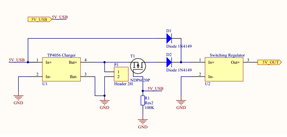
 warm gale
Hello, I'm looking for help finding a relay socket. I've been searching all morning and I cannot for all my Google foo find a socket for those small 5 pin mechanical relays.
For example Omron G5LE-14
sleek monolith
@unique patio . ive got a question. in this current arrangement will it backfeed 5v to the batter when the charger is plugged in?

temu
Check out this 5p 40a waterproof car relay long life automotive relays normally open normally closed dc 12v 24v relay for head light air conditioner on Temu. Don't miss these great deals. You may also like other Industrial & Commercial products.
unique patio
sleek monolith
<@329766224093249548> . ive got a question. in this current arrangement will it ...
It shouldn’t. Which pin or connection are you worried about?
sleek monolith
sp when its plugged into the charger module it will output 5v, skip the module and feed it to the battery?

i think i need to remove the top left red wire. correct?
warm gale
sleek monolith
<@223582057907879953> like this? https://www.temu.com/5p-40a-waterproof-car-rel...
That link appears to be busted
sleek monolith
just search temu relay connector
they have singles and relay blocks and everything in between
warm gale
Those are all automotive relay I need through home PCB relays
unique patio
sleek monolith
i think i need to remove the top left red wire. correct?

Connect USB on the Itsy and the 5V pin on the charger together. Do NOT connect 5v pin on the charger to BAT on the Itsy. I'm assuming you are not feeding the charger with its own USB cable.
the top power rail is +/- for the battery, so it goes to to the battery, to the BAT pin and GND on the Itsy, and to BAT and GND on the charger
tough matrix
Just wanted to share experience..
I have created a custom SAMD21G18-based board and wanted to make it properly supported in arduino IDE.
It required:
- modifying, compiling, and flashing the bootloader
- creating proper variant.h and variant.cpp files describing board pins
- building board support package, with platform.txt, etc, then zipping it
- creating
package_myboard_index.jsonfile
I did all that, but it took me a huge amount of time - like you wouldn't believe it.
But almost all of it could be automated.
I can easily imagine a python script that would take variant.h, variant.cpp, and a small config file with basic info (board name, USB PID and VID, LED pin for bootloader, and a couple of other things), and spitting out the rest - automatically building bootloader, creating board.txt file, zipping the archive, creating index.json file, etc.
Is there such a tool? Adafruit's samd package has a script that does one small part of it, but the rest you have to do by hand.
 hushed smelt
Need some help with measuring battery impedance https://www.adafruit.com/product/5035 the data sheet has a section for impedance but it's blank, on every PKCell battery datasheet in Adafruit's inventory. 😦 Anyone have one that is good with impedance testing? Figure this is the best place to ask, it's beyond my skill level.

Lithium-ion polymer (also known as 'lipo' or 'lipoly') batteries are thin, light, and powerful. The output ranges from 4.2V when completely charged to 3.7V. This battery has ...
distant raven
tough matrix
Just wanted to share experience..
I have created a custom SAMD21G18-based board...
Seems like it should be easy enough to do. I wonder if Stargirl has done it.
latent jungle
hushed smelt
Need some help with measuring battery impedance https://www.adafruit.com/product...
Battery Impedance is generally measured with an AC signal. (Other wise, it'd be called resistance.) Why is its value critical (for you)?
It also changes over time.
hushed smelt
latent jungle
Battery Impedance is generally measured with an AC signal. (Other wise, it'd be ...
To modify the battery gauge library for the LC709203F (used on the ESP32-S3 Feather) I need to figure out the impedance of the battery apparently. https://github.com/adafruit/Adafruit_CircuitPython_LC709203F/blob/7f2d4bd65b207518e924cedc6d31d5050194de64/adafruit_lc709203f.py#L118
That's the direction Gamblor provided #circuitpython-dev message
I'm not even sure I have the equipment to do it. All I have is a multimeter and some resistors. I don't own a 0 ohm resistor either. Been looking it up online and seems kind of out of my comfort zone.
latent jungle
hushed smelt
To modify the battery gauge library for the LC709203F (used on the ESP32-S3 Feat...
I'm confused. That line in the code has nothing to do with impedance.
(and I can't fathom how impedance would be used to determine battery life in an application)
hushed smelt
Looking at the datasheet (https://www.mouser.com/datasheet/2/308/ENA2237-D-321387.pdf) there doesn't seem to a limit. The values in the library are written to a register that says "Compensate for total impedance between the Battery and Fuel Gauge". So I think you could add more values but you would have to know what value to set. Or measure the impedance. The only limit seems to be that is measures 1 cell batteries.
latent jungle
Compensate for total impedance between the Battery and Fuel Gauge
between is the key word here...
hushed smelt
That's what I was told so that's why I'm here. I don't know enough to know if that is the right approach or not. I can manually set new values by modifying the library but I have no idea if that will yield a good or bad result.
latent jungle
It appears to be a value to compensate for the impedance of the wires/bus bar between the battery pack and the IC.
hushed smelt
The library only seems to set the capacity but I have a feeling there are registers behind the scenes that might need more info than just the capacity.
Yes, the problem is I have no idea what that means. 😅
Wouldn't have a clue on how to go about getting that value.
latent jungle
You would use a network analyzer to measure the impedance of the bus bar / wires between the battery and the IC.
(hint: it probably doesn't matter in most situations.)
hushed smelt
Yeah kind of what I was thinking. I don't have one, only a multimeter with very basic options.
worldly schooner
hushed smelt
Need some help with measuring battery impedance https://www.adafruit.com/product...
Better question is WHAT is between the battery and IC. There is always some parasititic capacitance and inductance, but when in doubt you can use the resistance of the connecting wires and traces as a baseline estimate.
The wire resistance can be estimated with wire gauge resistivity * length, and the board traces you can either measure with some Wheatstone bridge circuit or calculate in your EDA software.
unique patio
hushed smelt
That's what I was told so that's why I'm here. I don't know enough to know if t...
this is probably pretty insignificant for short wires
clever shadow
Anyone here a PIC expert? Trying to program a bare chip for the first time.. only used to AVR or ESP's.
spice turtle
clever shadow
Anyone here a PIC expert? Trying to program a bare chip for the first time.. onl...
I can help a little bit with this, what do you need?
clever shadow
spice turtle
I can help a little bit with this, what do you need?
I think I got it going. In the end I needed both Vpp and Vdd connected. It's a PIC12LF1571. Is Vpp always needed?
spice turtle
clever shadow
I think I got it going. In the end I needed both Vpp and Vdd connected. It's a P...
Yes. Or else it wont get programmed
spice turtle
clever shadow
I think I got it going. In the end I needed both Vpp and Vdd connected. It's a P...
also dont forget the LF series might only go up to 3.3V, so dont forget to limit your VDD
clever shadow
spice turtle
also dont forget the LF series might only go up to 3.3V, so dont forget to limit...
Ok. I wonder if there are AVR's that have similar low-power consumption in sleep. The datasheet for PIC12LF1571 is impressive.. nA while sleeping
I built Ted Yapo's tritiled
 spice turtle
clever shadow
Ok. I wonder if there are AVR's that have similar low-power consumption in sleep...
spice turtle
clever shadow
Ok. I wonder if there are AVR's that have similar low-power consumption in sleep...
If you look at the newer 18FxxQ series, or the newer 16F series (forget which ones), they have roughly the same stuff too
There might be, but they also use a different core.
clever shadow
I'm fine with that, the code is basically, sleep, fire a pulse, sleep.
spice turtle
So EEVblog kind of went over the specs a bit in detail. Yes hes comparing STM32's to a PIC24 but its worth watching:
https://www.youtube.com/watch?v=mN4obUsJXVY

Which microcontroller is better for the new project, the ST ARM STM32L or the Microchip PIC24F. Datasheet power consumption comparisons. All may not be as it appears...
Part 3 of the new project series.
If you find my videos useful you may consider supporting the EEVblog on Patreon: http://www.patreon.com/eevblog
Forum: https://www.eevblog.com...
clever shadow
PIC16F15213 looks like a newer PIC drop in replacement and about 40% cheaper.
God, I hate STM purely from their need for Java for their selection too 🙂
spice turtle
Yea PIC pricing is funny like that. I have in my cart a few dsPIC33EC's because they are literally cheaper than the 8 bit PICs lol
clever shadow
spice turtle
Yea PIC pricing is funny like that. I have in my cart a few dsPIC33EC's because ...
Old part = up the price 🙂
spice turtle
(but also, I need speed for math for my current project)
supple pollen
clever shadow
Ok. I wonder if there are AVR's that have similar low-power consumption in sleep...
My go-to for low power is TI's MSP430FR series
spice turtle
clever shadow
God, I hate STM purely from their need for Java for their selection too 🙂
I personally like MCC for pics, only because I really dont want to mess with bare metal code. It removes a lot of the guess work and code generation imho
supple pollen
Need for Java? Weird.
clever shadow
whistle dang. PIC16F15213 , 900nA in sleep.
spice turtle
clever shadow
I'm fine with that, the code is basically, sleep, fire a pulse, sleep.
Oh, down to these currents though, you really have to pay attention to your other components. I doubt the PIC will be the highest thing when it comes to current
clever shadow

GitHub
TritiLED: multi-year LED glow markers. Contribute to tedyapo/tritiled development by creating an account on GitHub.
Other then pulsing the LED, you're right, but there is a lot of time spent sleeping.
spice turtle
clever shadow
https://github.com/tedyapo/tritiled
favorited 🙂 thanks
clever shadow
spice turtle
favorited 🙂 thanks
https://github.com/gcormier/kitritiled add this one too 😉

GitHub
KiCad port of Ted Yapo's tritiled. Contribute to gcormier/kitritiled development by creating an account on GitHub.
Ted's the genius I'm just porting it to KiCad and making it easily made from our favorite overseas fab
I just got my first batch.
 spice turtle
When I saw the first version I said to myself "why didnt he just use a PIC to control the fet?That works" then I saw V2 lol
I built something similar (a boost converter) from scouring the microchip app sheets
https://github.com/chrissavage2300/PIC12F1501-Boost-Converter

GitHub
A circuit based on appnote TB3102. Contribute to chrissavage2300/PIC12F1501-Boost-Converter development by creating an account on GitHub.
clever shadow
It'd be nice to ditch the monostable.
spice turtle
It looks like they did and were originally using it as a driver. But then they combined two outputs to control the fet
err or is that V3?
clever shadow
V3 has the monostable. V2.2, you're right
spice turtle
Yes, its version 3 😅 😬
clever shadow
And the first mosfer is just for reverse polarity
which in V3 is just 100ohm resistor
He has some really detailed stuff on hackaday on tuning all this. It's not even worth the effort/time really for me. Maybe I'll do one without the monostable and ATTiny13A and see how it goes.
I mean, I GUESS i can change the cell once every 2 years instead of every 4? 😄
spice turtle
Im slightly confused about the purpose of it though. You can create monostable timers in a PIC
clever shadow
Faster burst?
spice turtle
Heck, some of them have a NCO and some sort of ramping function
clever shadow
This guy did it on an AVR with just a mosfet and inductor. Interesting note here though https://github.com/hexagon5un/everled/tree/master/code#microseconds

GitHub
Run a dim LED + microcontroller on 10 uA? Sure! A ripoff of Ted Yapo's Tritilight Project - hexagon5un/everled
spice turtle
yea, basically a boost converter for a single LED. Kind of a more advanced joule thief in a way
"The AVR draws as little current as possible by spending almost all of the time in power-down mode, being periodically woken up by the watchdog timer."
Interesting. On some of the newer PICs you can run things like PWM while the main CPU is off
clever shadow
Honestly, the LED on this one even is too bright 🙂
spice turtle
you could reduce the time its ON, which means you can sleep longer
clever shadow
spice turtle
you could reduce the time its ON, which means you can sleep longer
I'm at the lowest amount before it starts to flicker I think?
I've only flashed his hex file, have not actually done any coding.
dark grail
clever shadow
I'm at the lowest amount before it starts to flicker I think?
flicker is more about the pwm rate
if its PWM'ing at 10hz and you have it on 1% of the time, that will be very visible
but if its PWM'ing at 10khz, and on for 1% of the time, it wont be visible
clever shadow
dark grail
flicker is more about the pwm rate
if its PWM'ing at 10hz and you have it on 1%...
Hmm ok. I'd have to see if I can get MPLAB and modify his code here https://github.com/tedyapo/tritiled/blob/master/software/tritiled30/src/tritiled_v30_selectable_runtime.c
dark grail
clever shadow
Hmm ok. I'd have to see if I can get MPLAB and modify his code here https://gith...
i'm guessing the pwm_period is what matters
and modes.h pre-defines a bunch of them
i think its not varying the duty cycle, but just the period, which is a very weird way of doing it
clever shadow
Yeah so at the value 5 in modes.h, that's the lowest brightness I can get before the flickering is too visible. I note there's hardcoded duty_cycles for PWM. https://github.com/tedyapo/tritiled/blob/89b66661e46b21a711d60125e53643f7a29003aa/software/tritiled30/src/tritiled_v30_selectable_runtime.c#L137
all a bit beyond my comprehension for now
dark grail
yeah, thats backwards, you want to keep the period constant, and vary the duty cycle
 fast tundra
distant raven
Seems like it should be easy enough to do. I wonder if Stargirl has done it.
fast tundra
distant raven
Seems like it should be easy enough to do. I wonder if Stargirl has done it.
I don't use Arduino, but I did a custom board def for a client for a SAMD21G17 device that was an absolute pain.
distant raven
fast tundra
I don't use Arduino, but I did a custom board def for a client for a SAMD21G17 d...
That instance was what I was thinking about