#help-with-hw-design
1 messages · Page 19 of 1
 pale umbra
like it dimensioned my parts with 10.0000 cm instead of 10.0cm
thankfully it was caught before the university send to the workshop to have it made for the next class to get visual feedback
otherwise it would have costs like 6000$ instead of 6$ 🤣
pale umbra
why not get a pi 4b since they are as rare or a video processing specific MCU ?
 idle python
pale umbra
why not get a pi 4b since they are as rare or a video processing specific MCU ?
idle python
pale umbra
why not get a pi 4b since they are as rare or a video processing specific MCU ?
because i need an sbc thats small
and i cant just get a video processing unit because i also need something to manage the lte module
right now im stuck wondering if a radxa zero on software codec is faster than a raspberry pi zero on hardware codec
pale umbra
I wasnt able to acquire a zero 😦 so I cant help much and I have no idea what a radxa is
idle python
pale umbra
I wasnt able to acquire a zero 😦 so I cant help much and I have no idea what a ...
radxa zero is like the raspberry pi zero but its much faster than the zero, and faster than the zero2
the only downside about the radxa zero is that it doesnt get enough software support
thats why you can still buy it
and you cant buy a pi zero nowadays
pale umbra
oh I could if I really wanted to. My local shop is an official reseller and doesnt accept non-local orders or internet orders
but Id have to walk to it
since Im in a small city and it's kinda niche vs the other products they sell (computer parts / car audio systems) the Pis often collect dust for a long time
idle python
pale umbra
since Im in a small city and it's kinda niche vs the other products they sell (c...
lucky
i live in romania theres probably only like 15 people who own a pi zero in this country
pale umbra
Like they have 8x PI4B 8GB atm at 134 CAD$ atm vs 110$ on canadian pishop
but they have an habit of getting confused in product description and sometimes you walk to the store to find out it was a case or a bigger product with a pi 4 not included in it or the wrong model number etc
idle python
pale umbra
but they have an habit of getting confused in product description and sometimes ...
still worth it
pi 4bs are pretty rare
pale umbra
mine was 135$ in basic starter kit package last june because I needed the cables / adapter / sdcard / sdcard reader flob etc
the flob also works on a computer so it's really handy
and support 3 sizes of sd-card
idle python
i wish i knew someone who had a pi zero atm
pale umbra
my makerspace put their 12 or so of each pi model in a big safe since a couple of years 🤣
they get them throught an educational channel / corporate sponsorship so Im not sure how long they have to wait
so is it better to buy the pi zero W or normal pi zero ?
meh nevermind they dont have a pi zero 2W without a kit...
idle python
pale umbra
so is it better to buy the pi zero W or normal pi zero ?
i dont see why you would buy a normal pi zero without wifi unless the normal pi zero is a lot cheaper than a pi zero w
idle python
pale umbra
meh nevermind they dont have a pi zero 2W without a kit...
cant they just grab a pi zero 2w from the kits and sell you it seperately?
pale umbra
no, usually the agreement with raspberry pi prevent them from doing so
it doesnt even show as out of stock
 supple pollen
idle python
i dont see why you would buy a normal pi zero without wifi unless the normal pi ...
supple pollen
idle python
i dont see why you would buy a normal pi zero without wifi unless the normal pi ...
Half the price, last I checked
 violet portal
g'day! hope everyone is well in Adafruit land
(this could equally be in #help-with-linux-sbcs I guess, but let's tryi here)
I am hooking up a Micro USB breakout I picked up yesterday to a Device Under Test; the terminals are labeled 1, 2, 3, 4, 5, SHL and the DUT just has D+/D+/Vcc/Gnd
DUT -> Breakout
Vcc -> Pin 1
D- -> Pin 2
D+ -> Pin 3
Gnd -> Pin 5
(Pin 5 / SHL are NC)
on the host side I am seeing
[  550.953227] usb 1-1-port3: Cannot enable. Maybe the USB cable is bad?
[  550.953891] usb 1-1-port3: attempt power cycle
[  552.121075] usb 1-1-port3: Cannot enable. Maybe the USB cable is bad?
[  552.973084] usb 1-1-port3: Cannot enable. Maybe the USB cable is bad?
[  552.973762] usb 1-1-port3: unable to enumerate USB device```
according to this, my pinout is ok... (and if it wasn't then the host wouldn't show anything)

on the DUT side, I am using a set of PCBite probes, qhich are designed for USB, SPI, CAN etc
but, thinking a signal integrity issue?

i have a short length of "ordinary" jumper/dupont cable connect the probes to the breakout; then a short USB cable (which I know is good as I use it for cellular modems) to the host
the USB port on the DUT should appear on the host as a 115200 Serial port, so not high speed at all
(but yes! this is horrible probing technique!)
 violet portal
Other info:
- the Host is a Raspberry Pi 400, running Bullseye lite 32bit
- have swapped the micro usb breakout for IC clips, same problem
I have a USB Type A Plug Breakout Cable with Premium Female Jumpers - 30cm long (https://www.adafruit.com/product/4448) on the way which can then go direct to the probe tips

If you'd like to connect a USB-capable chip to your USB host, this cable will make the task very simple. There is no converter chip in this cable! Its basically a plain USB cable ...
the probes are PCBite SQ10 from Sensepeek (https://sensepeek.com/4x-sq10-probes-with-test-wires)
 supple pollen
violet portal
g'day! hope everyone is well in Adafruit land
(this could equally be in <#53814...
supple pollen
violet portal
g'day! hope everyone is well in Adafruit land
(this could equally be in <#53814...
Could be the pins are numbered differently on that breakout, could be the wiring just isn't clean enough for USB. Even though you're taking to a USB peripheral that's not doing something data intensive, it might still be trying to negotiate at high/full speed. You could also have a ground loop problem. You probably want to hook up the shield to minimize interference.
violet portal
supple pollen
Could be the pins are numbered differently on that breakout, could be the wiring...
yeah, I am pretty sure its a signal integrity issue... i just don't want to admit it 😆
and agreed on all your points... though as these are Test Points, i think my usage of probes is ok - though (and I have never probed USB before) I wonder what the best practice for this is? after all a USB cable is twisted pair and I just have long test leads flappin' in the breeze... the USB Breakout cable should be a good help
supple pollen
I dunno, "cannot enable" seems like it might be a power issue. Some useful discussion here https://askubuntu.com/questions/206614/usb-slots-stop-working-suddenly-from-time-to-time/833569#833569
violet portal
supple pollen
I dunno, "cannot enable" seems like it might be a power issue. Some useful disc...
that's true; i've been stung by power issues before on Pi's with USB... I have a log on it somewhere...
hrmmm here
[  212.557335] usb 1-1.4: new high-speed USB device number 18 using dwc_otg
[  212.997344] usb 1-1.4: device not accepting address 18, error -71
[  213.097327] usb 1-1.4: new high-speed USB device number 19 using dwc_otg
[  213.537334] usb 1-1.4: device not accepting address 19, error -71
[ 213.537467] usb 1-1-port4: unable to enumerate USB device```that turned out to be an undervoltage issue
this is interesting... https://forums.adafruit.com/viewtopic.php?f=20&t=122375; this was a bad batch of pre-programmed microcontrollers
supple pollen
I considered asking what the target device actually is
violet portal
the target device is a cellular modem, and this is the debug USB port
after some more reading (and mea culpa, I have never dug into USB, and so I enjoy when bugs like this happen - good chance to learn) - the ID Pin on the micro USB should also be grounded? (https://electronics.stackexchange.com/questions/35462/why-does-micro-usb-2-0-have-5-pins-when-the-a-type-only-has-4)

Electrical Engineering Stack Exchange
What is the extra, 5th, pin on micro usb 2.0 adapters for?
Here is an image with the different connectors. Most of them have 5 pins, but the A-type host only has four.
(source: wikimedia.org)
 supple pollen
Wiring integrity is extra important with a cellular modem, the cellular signal is a high powered transmitter than can interfere with nearby wiring. Maybe adding some shielding between the cellular antenna and your wiring could help. Additionally, cellular modems draw a significant amount of power. It might be worth hooking up the power lead to a separate supply to see if that helps.
violet portal
absolutley; unfortunately I can't provide more info than i have; but suffice to say the board itself is all good; and these test points are debug and go direct to the USB of the modem - so; 99.9% the issue is my crappy wiring effort; if i have to, ill solder a shielded USB cable direct to the TP and bypass everything else - but if I can avoid that, it would be best for all involved (i have limited test devices) - so, fingers crossed if i can put a USB cable direct to the test probes (the adafruit cable i mentioned) that will resolve the issue 🙂
a few things to try anyway 🙂
 vast flume
Hey guys, still trying to figure out this dang i2c sensor :(. I was looking through the datasheet again and found this:

And this is my setup:

Is it possible that not having those 10 ohm resistors could be causing this?
Its being powered from a regulator so I didn't think it would be an issue
 cursive sentinel
It has a warning about limiting inrush current. 10us is pretty slow.
vast flume
Is it possible it could come back to life if I add that resitor now or no?
cursive sentinel
to avoid damages from repeated power cycles
If this happened it is irreversible.
cursive sentinel
repeated power cycles
It is not immediate
vast flume
Ik but I've gone through 3 sensors on this version of the board so I would've expected at least one to be discoverable before dying
Literally worked for hours on the last version of the board
 rustic linden
Can/should you connect VDD and VDDIO?
vast flume
What do you mean?
 surreal tangle
vast flume
And this is my setup:
surreal tangle
vast flume
And this is my setup:
It looks like you need to tie CSB to VDDIO... "For using I2C and I3C, it is recommended to hard-wire the CSB line to VDDIO"
 supple pollen
I'll ask again: are other I2C devices on the bus working?
vast flume
supple pollen
I'll ask again: are other I2C devices on the bus working?
Its the only i2c device on this pcb
I have it on another pcb which does have 2 other devices on it as well but that one is beyond screwed at the moment so I cant test
vast flume
surreal tangle
It looks like you need to tie CSB to VDDIO... "For using I2C and I3C, it is re...
In the datasheet it also says that you can keep csb floating bc it has an internal pullup
supple pollen
Presumably you do have I2C pull-up resistors
supple pollen
Then I'm guessing it's an orientation problem. That orientation illustration on the data sheet is confusing at best.
vast flume
Its so confusing
supple pollen
4.7k seems fine.
vast flume
But I was able to confirm the orientation is correct
supple pollen
How did you confirm that?
vast flume
Apparently my iphone 14 has a macro lens that I never knew about
Zoomed way in and was able to see the pin 1 marker on the underside of the sensor
Flipped it over and realized the dot on the top of the package isn't the vent hole, it is a pin 1 marker
The vent hole is actually 2 holes in a different corner
 surreal tangle
vast flume
In the datasheet it also says that you can keep csb floating bc it has an intern...
surreal tangle
vast flume
In the datasheet it also says that you can keep csb floating bc it has an intern...
Are you sure it is enabled by default... This makes it sound like you have to enable the pullup
 vast flume
Bruh thats so stupid
So it has an internal pullup but you need to communicate with it over i2c to enable it 🤦♂️
Why does that even exist
surreal tangle
Doah
supple pollen
This does not appear to match
 pale umbra
well they says to uses 71000 to 130000 pull-up externally
but I cant find the value of the internal pull-up
vast flume
supple pollen
This does not appear to match
Yeah it was in the wrong orientation in that picture 😅
That was before i realized those holes in the bottom right are actually the port holes
supple pollen
The internal pull-up isn't a resistor, it's some weird thing like a MOSFET current source
vast flume
Is it possible to fix this in software?
By communicating over a different protocol to enable the pullup?
supple pollen
I'd just connect the external pullup.
vast flume
How?
supple pollen
Connect a resistor from the CSB pin to 3V3
vast flume
So I have to order a new pcb 😦
supple pollen
You didn't break out that pin?
supple pollen
Do you have any more unassembled PCBs?
vast flume
Yea
In theory can't I just remove the sensor and bridge the two pads

(Ignore the unrouted nets, making some other changes)
supple pollen
That should work, as long as nothing shorts to the bottom of the housing
vast flume
Ok
pale umbra
eh that internal pull-up thing is kinda ridiculous . Kinda like an ISP that tells you to check the knowledge base at some URL to fix the internet not working when you cant connect to the internet 🤣
supple pollen
Yeah, that's some Verizon level dopiness.
vast flume
lol
vast flume

Well this is my attempt
I tested and confirmed that the little wire is connected to 3v3
Theres no way for me to confirm if it is/isn't connected to csb
But it doesn't seem to work
After removing the sensor this is how it looks

So it def was connecting the two pins together
supple pollen
I'm worried that the wire was shorting to the metal case of the sensor
supple pollen
I think you have the right idea, but a) the wire may be thick enough it keeps the other pads from making good contact, and b) the possibility of a short circuit. Unfortunately, I don't have a good suggestion. Insulated wire or polyimide tape might help with the short circuit issue, but it will make it even thicker, which is worse for the "good contact" issue.
 supple pollen
If I were you, I'd tack wires to the I2C pins and run them to some other I2C device off-board to see if the I2C bus itself is working.
vast flume
Just tested with an i2c display
It found it
So I guess that rules out an i2c bus issue
 distant raven
The signal integrity comment only applies to signals over 10GHz, IBM disproved the right angle signal integrity myth a while ago with empirical evidence.
If right angle traces were bad for integrity, no one would use inverted F, or square meandered Wi-Fi antenna or use via for that matter
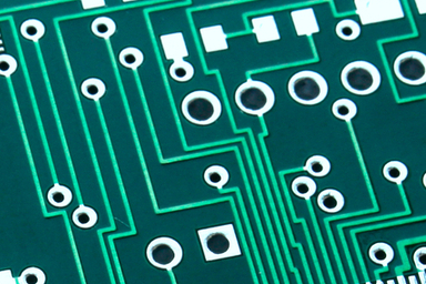
Northwest Engineering Solutions | Blog | It's time to put the myths about right-angle PCB traces to rest. Here’s what every designer should know about right angle PCB traces.
 rigid plume
Yeap I agree, manufacturing processes for PCBs can sometimes struggle with right-angle bends.
Although I still think it is best practice to not do 90* angles. But it just depends
distant raven
Sure, manufacturing is the biggest concern here. Acid traps, adhesion..
For the average design though, 90 vs 45 is going to be an aesthetic choice
rigid plume
Yes definitely, many prototype board houses like JLCPCB should be able to handle 90* perfectly.
distant raven
Or if you’re making like.. a 40G board, you’re going to use smoothed meandering for traces, not even rough 45
rigid plume
More arc like in that case
 meager coral
what is the best practice for attaching gears to the end of servos? is there a cad file for the pre-installed end piece?
rigid plume
meager coral
what is the best practice for attaching gears to the end of servos? is there a c...
What's the application?
meager coral
two applications: 1. is a rack and pinion to dispense starburst. 2. is spinning a spool of 3mm rope to lift and lower it.
both with a continuous servo
cursive sentinel
It's really a matter of what you are trying to accomplish. Any time your trace length matches up with an integer multiple of the wavelength of your signal (or a harmonic of it) you can get reflections. Digital signals with fast edges can have significant harmonics high above the switching frequency. In the case of antennas, you often want that reflection.
cursive sentinel
distant raven
Sure, manufacturing is the biggest concern here. Acid traps, adhesion..
Acid traps are not nearly as much of a concern anymore, and if they were you'd have trouble using surface mount packages smaller than SOIC.
rigid plume
meager coral
two applications: 1. is a rack and pinion to dispense starburst. 2. is spinning ...
you could attach a pinion gear directly to the servo shaft.
or a hub or horn
meager coral
the servo shaft is the white nubby guy at the end?
do I just make a circular hole that size and use loctite on it?
vast flume
meager coral
do I just make a circular hole that size and use loctite on it?
Thats worked for me if you're FDM printing it. Just make sure to not get any glue inside of the servo itself. In my experience, hot glue has worked well since its too thick to get inside
distant raven
cursive sentinel
Acid traps are not nearly as much of a concern anymore, and if they were you'd h...
Right, modern processes circulate the etchant which helps prevent trapping
 elder peak
Acid traps are such a "Are we talking about the D&D adventure or PCB" moment.
pale umbra
nice to have acid traps in PCB in case you encounter a troll
 graceful sparrow
vast flume
Thats worked for me if you're FDM printing it. Just make sure to not get any glu...
graceful sparrow
vast flume
Thats worked for me if you're FDM printing it. Just make sure to not get any glu...
Oh gosh, when I was in middle school shop class.... "hot glue and duct tape fixes everything" was the word... bringing back memories.
vast flume
Hey guys have a quick question about the esp01
It turns out that that is what has been shorting out my other pcb (I think, with 99% certainty)
The wifi antenna on it gets extremely hot
But the thing is, I have no idea what could be the issue

This is how I connected it, super simple
Nvm turns out its a footprint issue 😅
vast flume
Actually never mind it seems that that wasn't the issue
I removed the esp-01 but I'm still unable to program the board and the inductor is still making tons of noise (and heating up)
I replaced the inductor and stm32 but still no luck
 tough matrix
meager coral
two applications: 1. is a rack and pinion to dispense starburst. 2. is spinning ...
tough matrix
meager coral
two applications: 1. is a rack and pinion to dispense starburst. 2. is spinning ...
for linear motion:
you can buy a ready kit: https://www.servocity.com/servo-driven-gear-rack-kit-single-gear-rack/
or just a pinion gear: https://www.servocity.com/all-servo-gears/

Welcome to ServoCity where you can get the parts you need to bring your ideas to life! From servos to switches, from actuators to Actobotics, we work hard to bring you the best components backed by unparalleled technical support
tough matrix
meager coral
two applications: 1. is a rack and pinion to dispense starburst. 2. is spinning ...
for spool: use a plastic spool like this: https://www.servocity.com/3410-series-servo-mount-winch-pulley-25t-spline-dual-spool-112mm-circumference/
or a combination of hub: https://www.servocity.com/servo-hubs/
and matching spool

Welcome to ServoCity where you can get the parts you need to bring your ideas to life! From servos to switches, from actuators to Actobotics, we work hard to bring you the best components backed by unparalleled technical support
supple pollen
vast flume
I removed the esp-01 but I'm still unable to program the board and the inductor ...
I doubt the inductor is the WiFi antenna
vast flume
supple pollen
I doubt the inductor is the WiFi antenna
I originally thought there was a short with how I connected the esp01 but if that was the short the inductor would've stopped being so noisy & hot
I'm using the same inductor on a different pcb where it works fine
To be fair in this board it is stepping down from a higher voltage (~16v down to 5v vs stepping 3.7v up to 5v)
supple pollen
It can do that if the inductor saturates
vast flume
What could cause it to saturate?
cursive sentinel
All inductors have a finite amount of energy they can store in their magnetic field. That's fundamentally what inductance is: it relates energy to current.
In SI base units 1H works out to be 1J/A².
1 H = 1 kg⋅m²/(s²⋅A²)
    = 1 kg⋅m²/s² ⋅ 1/A²
    = 1 J/A²
Just looked it up and its also inducance * current, and typically saturation is ~0.3
Also it looks like mine is rated up to 4 amps

Idk how i would figure out the current in the buck converter circuit though 😅
cursive sentinel
On average it will be whatever your load is drawing, but the peak current can be considerably higher.
This is called ripple current and how you would calculate it depends on the design of the converter.
vast flume
I see
The average current should be essentially 0 though unless there is another short which is why I'm confused
All thats in the circuit is an stm32, 3 memory modules, a pressure sensor, and an imu
I've tested without the imu and pressure sensor and it still had the same issue
Also tried measuring the current into the circuit and it was much lower than 1a
cursive sentinel
vast flume
The average current *should* be essentially 0 though unless there is another sho...
How so?
vast flume
cursive sentinel
How so?
Just bc theres not really anything on this board
Besides the stm32 and sensors
cursive sentinel
That doesn't make the average current 0.
The first thing you'll have to determine is if your regulator is running in CCM (continuous conduction mode) or DCM (discontinuous conduction mode). In DCM the inductor is fully discharged between switching cycles.
vast flume
I thought you said the average current is whatever the load is drawing?
This is the datasheet for the buck converter I am using
cursive sentinel
vast flume
I thought you said the average current is whatever the load is drawing?
Yes, but you implied that the load is drawing nothing.

I think the first thing you want to do is determine your idle and peak load.
Also, what is your input voltage?
vast flume
15v
cursive sentinel
Output of 3.3?
cursive sentinel
What inductor are you using?
vast flume
cursive sentinel
Inductor, not regulator
cursive sentinel
But you don't have any idea what your board draws while idle?
vast flume
Barely any
If you mean the current pulled by the regulation circuit I'm not too sure
But everything downstream of that is pulling an extremely minimal amount of current
I can show you the schematic if you want to see
Or the layout
cursive sentinel
Schematic would be fine.
vast flume
Ok one min
Heres the voltage regulation circuit

Heres the microcontroller

Heres the onboard storage

Heres the sensors

And then heres the display
 cursive sentinel
22uF 6.3V ceramic caps is pretty sketchy with a 5V output. Ceramic caps—especially ones with a large capacitance in a small package—have a significant DC bias characteristic. You need to derate for the reduced capacitance.
https://community.infineon.com/t5/Knowledge-Base-Articles/DC-Bias-Characteristic-of-Multilayer-Ceramic-Capacitor-MLCC-KBA223633/ta-p/250035

Version: ** Question: How does MLCC DC bias characteristic affect a power system? Answer: The Multilayer Ceramic Capacitor (MLCC) DC bias characteristic refers to the capacitance change of the ceramic capacitor with the applied DC voltage. As the applied DC voltage increases, the ceramic capacitor...
vast flume
I have some other caps should I try swapping it out
cursive sentinel
Yeah might be a good idea. You could also probably get away with putting more of them in parallel.
What caps are you using now?
vast flume
I actually think I already did that
I have 2 22uF caps in parallel
So 4 total
Should I try throwing some more in parallel?
cursive sentinel
Also are you able to hook a scope to the output?
cursive sentinel
Bummer
vast flume
Yeah for real
cursive sentinel
Do you have a datasheet for those caps?
cursive sentinel
Ok they don't have a graph for your specific cap in the datasheet, but here's one from the same family. You can try putting more caps on, but I can't guarantee you it will help. As a general rule the X5R dielectrics are crap.

Gotta go for now.
It wouldn't surprise me if your actual capacitance is 30 or 40% lower than you were expecting.
vast flume
Ah I see
Thanks for the help! I'll just keep adding them in parallel and see what happens then
distant raven
Also a good point along this, larger packages derate at a slower pace of voltage increases
0805 and 1206 will have better derating than 0603 and much better than 0402 and smaller
 rigid fiber
O'm trying to make a schematic for this circuit from an Ali Express item page forna tiny OLED display. Q1 and Q2 are confusing me. The symbols looklike depeletion type mosfets, but I can only find FDN338P & FDN335N as enhancement type. I thought that you needed to wire depletion vs enhancement differently?
 rigid fiber
But I think what it's wanting to do is Q1 is ESD protection a sthat seems to be a pull-up resistor to keep the gate closed and let current flow Vbat (which powers the tiny display). And R2 looks like a pull-down resistor which keeps Q2's gate opne, preventing current to VDD unless GPIO is asserted high.
Does that seem correct? Or did Is just show myself to be a dummy? 🙂
vast flume
@cursive sentinel @distant raven Well I swapped out the caps that were being used with some 16v 22uf ones, and that seems to have maybe brought the noise down a little bit but I'm not 100% sure. I'm still not able to program the stm32 for some reason though 😦
distant raven
vast flume
<@578805364019953715> <@728676724522352733> Well I swapped out the caps that wer...
Do you have a reset button somewhere?
I’m curious why you didn’t connect reset to the SWD headers
vast flume
distant raven
Do you have a reset button somewhere?
Nope 😦
Haven't needed one before with this chip
Albiet I'm a complete noob
But my other stm board that I made is able to be programed with no issues
distant raven
Idk, usually reset is a signal you need for stable swd, or it’s recommended anyway by the developer docs from Arm
vast flume
I see
Is there a way I can "manually" trigger this to test?
Oh actually I guess not bc the pin isn't connected
distant raven
You can use a bodge wire
 dry pelican
rigid fiber
But I think what it's wanting to do is Q1 is ESD protection a sthat seems to be ...
dry pelican
rigid fiber
But I think what it's wanting to do is Q1 is ESD protection a sthat seems to be ...
The MOSFETs are probably just for switching power to VBAT
 echo zephyr
i have 3 methods of splitting routes for buttons but i need to know which gives the least voltage loss, on the first one i think that one wire could have less voltage because some electrons could be on a single side, on the second if the first button was pressed then the second button would get less or no voltage, on the third one the result may be the same as the first one. which is the best method or is there some other method i haven't used?

the pcb is designed to handle multiple buttons being pressed without like more than 1V loss
rustic linden
i think voltage loss in any of those will be negligible by themselves, because it depends on the loads connected to the buttons
echo zephyr
rustic linden
i think voltage loss in any of those will be negligible by themselves, because i...
alright then, I’ll use the first one and hopefully the electricity from the buttons won’t come back and create arcing from 90 to 135 degree angles
oh the maximum is 90 degree angles and 0.3mm routing width shouldn’t produce arcing with 3.3V
rustic linden
You'd need so much more to arc
echo zephyr
makes sense
the voltage and current is too low to cause even small arcing
why did I just realise that
echo zephyr
also another question, is a via with 0.915mm diameter and 0.458mm drill diameter enough for 5V with 1A?
supple pollen
"Probably". It depends on the copper weight, via fill weight, and hole accuracy. Normally if I'm designing something to carry non-trivial current, I'll use several vias ("via stitching")
distant raven
I like to do via stitching for large current with smaller via because I make increase the overall surface area for current to travel
supple pollen
Good point: a single via will funnel the current down to the area of the trace that's nearest the via, wasting part of the current capability of the trace and increasing voltage drop, heating, etc.
idle python
how many mbps could a raspberry pi zero handle on download and upload
deciding whether i should get a7670e or sim7600g-h
supple pollen
I'm guessing the Pi won't be the bottleneck, although if you're sending data to the SD card, that could be.
idle python
supple pollen
I'm guessing the Pi won't be the bottleneck, although if you're sending data to ...
no im trying to stream video from csi camera with a 4g m odule
average upload speed is 11mbps where i live but a7670e has a max upload rate of 5mbps
supple pollen
1.2MBps seems to me like something the Pi could handle, depending how much much processing is involved. However, I really don't know. It would be easy enough to test just having it stream from the camera through one of the USB ports. It may also depend on what the interface to your cellular module is. PCIe is plenty fast, but I don't think the Pi supports that.
idle python
supple pollen
1.2MBps seems to me like something the Pi could handle, depending how much much ...
the module i found is usb only
supple pollen
Ah, then a streaming-to-USB test will be pretty representative of the Pi's capabilities.
idle python
supple pollen
Ah, then a streaming-to-USB test will be pretty representative of the Pi's capab...
representative?
idle python
supple pollen
1.2MBps seems to me like something the Pi could handle, depending how much much ...
i did a quick test on obs and a h264 stream at 1920x1080 60fps with 4000kbps bitrate is only 3000kbps on bandwidth
baseline profile btw
 woven bluff
pi4B can do 54Mbps on 5G at best
idle python
i bought the a767e
vast flume
How possible is it that I've killed my Segger J-Link programming adapter? Neither of my 2 pcbs is able to be programmed now so I'm super confused
I guess I'll try ordering some more stm32s to rule out having killed both microcontrollers
supple pollen
It might be worth using some other piece of gear (depending on what you have available) to see if the J-link is producing the expected signals
Or emulating the protocol with something else to see if your PCBs answer up
 dusky raptor
Is there anything I should add between the rasberry pi pico and the rotary encoder???
 supple pollen
You probably want to hook up the ground
Ah, I see it now, the dark blue on black didn't show up very well on my screen
vast flume
If I've burnt out an stm32 is it possible that the power and ground pins could short?
woven bluff
if you power it up and the chip gets hot immediately then it's wasted.
 jade wedge
I'm trying to work out the usage of a shift register, and I want to make sure I'm reading this correctly. The goal is to read the state of 8 dipswitches one at a time, and I think the 4021B will do this for me.
https://www.ti.com/lit/ds/symlink/cd4021b-q1.pdf
Now, if I'm correct, I can latch the 8 inputs by bringing pin 9 high, then pulsing pin 10 high. After that I can bring 9 low, and get the data out on pin 3. Shifting with positive pulses on pin 10. Pin 11 can be tied to either ground or VCC depending if I want the registers to fill with highs or lows.
That all sound about right? I don't want to use an I2C input expander as I don't need anything fancy from this, and I'm also hoping to limit my use of external libraries.
supple pollen
A 4021? That's old school. I usually reach for a 74HC595 for such duties.
jade wedge
Mostly going by what's available on Digikey in thru hole format.
Plus they have the 597 which seems to be more complex, and has a less helpful datasheet.
supple pollen
Ah, that makes sense. I like the '595 because its popularity yields helpful pages like https://docs.arduino.cc/tutorials/communication/guide-to-shift-out. These look to be in stock if you care to go that way. https://www.digikey.com/en/products/detail/texas-instruments/SN74AHC595N/375877
jade wedge
Oh, also the 595 is the opposite function. Unless I'm reading it wrong. The 595 looks like it takes a serial input and makes it parallel. I have parallel input I need to make serial.
supple pollen
Whoops, sorry about that. I had it backwards.
jade wedge
Well, assuming I have the usage of the 4021 correct, I have at least built myself a schematic, and board. Ok, they're probably not that great, and I'm definitely putting the cart before the horse, but I've got little else to do for this project while waiting for parts, and learning how to program an ATTiny directly. Still, I don't think they're too bad for a first try. The idea is a simple NeoPixel style controller board. I don't think I'll need a cap for smoothing on the LEDs as I'm only going to use two of them. Mildly annoyed that I couldn't find a footprint for a through hole USB Micro connector.


 supple pollen
Good use of a resistor network.
jade wedge
Figured better than 8 discrete pulldown resistors. Also took a bit of finagling to get the routing to not require a huge amount of over/under.
I realize now though that I'll likely need at least one to pull reset high on the ATTiny. Probably not good to leave that floating.
But hey, like I said, I've got time to work on this.
Breadboarding is first anyway.
Ahh... Phooey. I can't use the 4021. "Quantity entered must be a multiple of 451"
Guess I'm learning the 74H597.
supple pollen
Ah, marketplace part? That's annoying. In this design, I took advantage of the ability to remap pins to make routing neater.
 jade wedge
Clever. In my case there is an advantage of swapping chips. 7 of the 8 inputs are on one side, and in a row. Super convenient for me.
supple pollen
Oh, I appreciate that sort of thing!
jade wedge
Indeed. Convenient, and visually pleasing. A proper flow of data from one end to the other.
vast flume
Hey guys, would somebody be able to help me fix the inductor heating issue on my buck circuit?
supple pollen
Remote debugging of switching power supplies is tricky, but I can try...
vast flume
What would be the first place to start at? 😅 I've tried adding more output caps in parallel & replacing the inductor
This is the current circuit for regulation

And this is the buck ic I'm using https://www.digikey.com/en/products/detail/monolithic-power-systems-inc/MP2307DN-LF-Z/5292007
woven bluff
SMPS is not trivial, you need at least a scope to find out what's wrong
supple pollen
It looks like it's hooked up wrong. As in the inductor does not go between the supply voltage and the SW pin
Oh wait, +5V is the output, not the input. Sorry, I'm used to seeing the input on the left and the output on the right.
What's the output current you're drawing? Which inductor are you using?
woven bluff
output filter cap voltage rating is too low
supple pollen
Also, layout is important in these designs. You have high currents and fast edges in the power side of the circuitry, which can easily couple to the feedback node and cause problems.
woven bluff
the schematic on the first page is for 3v3 output
supple pollen
If the capacitors are getting warm, you have an overvoltage, ripple current, or leakage issue (monolithic ceramic capacitors with high capacitance in a small volume are particularly susceptible to this)
woven bluff
did you follow recommended layout on page 10?
also why did you chose a chip that is NRND?
vast flume
supple pollen
What's the output current you're drawing? Which inductor are you using?
Shouldn't draw much current at all, since I don't have much downstream currently. Just have an stm32, and some sensors. I've tested with those all removed, and even with the 3.3v linear regulator removed to remove the 3.3v circuit, but it still occurs
vast flume
woven bluff
output filter cap voltage rating is too low
I've since switched to a higher rated cap (16v) https://www.digikey.com/en/products/detail/samsung-electro-mechanics/CL21A226MOCLRNC/5961264
vast flume
woven bluff
also why did you chose a chip that is NRND?
Someone here had recommended it to me as one of the easier chips to get working I think
woven bluff
x5r is ok, but it's better to use x7r
supple pollen
I may have mentioned that chip, because it's the one used in scads of inexpensive but solid UBECs including the one AdaFruit sells.
vast flume
woven bluff
did you follow recommended layout on page 10?
Actually I didn't 😅 . Here is what my layout looks like:
 woven bluff
traces too thin, inductor too far
supple pollen
Feedback loop too big, it'll pick up noise inductively and capacitively
The long traces in the switching loop broadcast signals like an antenna, transformer, and capacitor all at once. The long traces in the feedback loop pick up those signals as noise, confusing the chip and causing it to operate improperly.
supple pollen
Shorten both the feedback and power loops.
From the datasheet, the PCB Layout Guide, paragraph 1 says "Keep the path of switching current short
and minimize the loop area formed by Input cap., high-side MOSFET and low-side MOSFET.", paragraph 3 says "Ensure all feedback connections are short and direct. Place the feedback resistors and compensation components as close to the chip as possible", and paragraph 4 points out "ROUT SW away from sensitive analog areas such as FB." All of these details are important for a switchmode power supply to operate smoothly.
vast flume
Ah ok perfect thanks
pale umbra
"2 V Sealed Lead Acid (SLA, VRLA) Battery Rechargeable (Secondary) 200Ah" - Why?!
elder peak
Are you feeling lead astray?
supple pollen
I've seen cells like that in phone company offices for power backup.
pale umbra
elder peak
Are you feeling lead astray?
No I just fail to comprehend why youd need such a long duration power source and ruins it with such a low non-standard voltage
supple pollen
Often there will be several such cells in series to provide whatever voltage the equipment needs. Having it in separate cells means several heavy items instead of a single massively heavy one. It also makes cell balancing easier, as the cell-to-cell connections are available. In the phone company office, there were 24 such cells in series to provide the 48V the switching equipment used.
dry pelican
vast flume
Just curious, how does trace length correspond to the heating?
Longer increases resistance, which increases power loss
I use ~1mm trace width per amp when I can
That's my rule of thumb
There are also calcs
vast flume
Thanks I'll keep that in mind!
I've just been using the same trace width for everything which obviously only gets you so far lmao
So ig I'd size the traces off of 4 amps? So 4mm?
distant raven
Do 2mm and 2oz copper, you should get the same carrying capacity
Less board space occupied. You should use 2oz anyway when possible with high current applications
supple pollen
Since it's the inductor that's heating instead of the traces, I suspect trace resistance isn't your current [pun intended] problem. But once you get that sorted, you may find you have some warm traces.
distant raven
I suspect there’s probably some strange induction loops in the board, non-optimal return paths increasing ESR
It’s amazing how you can introduce noise by having not great return paths for signals
Which is a different discussion
But something I’ve been thinking about recently
supple pollen
The larger the loop area on the switched side, the more noise it transmits. The larger the loop area on the feedback side, the more noise it receives.
distant raven
Yup yup
dry pelican
vast flume
So ig I'd size the traces off of 4 amps? So 4mm?
Why do you need that much current?
vast flume
dry pelican
Why do you need that much current?
Its a buck converter so the datasheet has the parts spec'd out to 4a
dry pelican
vast flume
Its a buck converter so the datasheet has the parts spec'd out to 4a
you only need traces rated for the max current the converter will be supplying
Here's my layout for an LMR51420 buck

probably not the best
but it works with no inductor overheating
dusky raptor
is this schematic okay ? I am really new to this project and I am trying to build a macropad of my own
 rustic linden
Here's a tip! You can use net labels so you don't have to individually wire up things, you can just place a label at the points you want to connect
supple pollen
Your LEDs won't be individually controllable, and they need current limiting resistors.
pale umbra
Is there a way to filter all available chip by connector types on digi-key (or another site) by anything that works in throught-hole or that is very easy to use an adapter for (like SOC) /TOS/those that have cheap socket you put them into ?
dusky raptor
supple pollen
Your LEDs won't be individually controllable, and they need current limiting res...
should I add current limiting resistor to each individual LED or just add a big one on parallel with them, also how much kohm/ohm should I add with them?
dusky raptor
supple pollen
Your LEDs won't be individually controllable, and they need current limiting res...
also about controlling individual led, I was hoping for a matrix configuration , but as this is my first board, I don't know how am I supposed to do it
supple pollen
pale umbra
Is there a way to filter all available chip by connector types on digi-key (or a...
Yes, DigiKey offers a general "through hole" filter, as well as more specific package filters
supple pollen
dusky raptor
should I add current limiting resistor to each individual LED or just add a big ...
You generally need a resistor per LED. For matrixing, you normally connect the anodes to various different GPIOs and the cathodes as well to various different GPIOs, and then scan through them by activation combinations of GPIOs to select the LED you want to light, and cycle through them.
jade wedge
I've been mulling over this 74HC597 truth table, and I think I can "cheat" my pin usage a little bit. I don't care about clearing the registers, so MR can just go straight to VCC. The clock pins can be combined as there's no case where both ST and SH can both accept a pulse. Which just leaves PL.
pale umbra
supple pollen
Yes, DigiKey offers a general "through hole" filter, as well as more specific pa...
I meant site side, without having to select hundreds of individual categories or at least being able to filter all ICs. Like from this page I dont see any filter and I would like to select all possible DIP-8/in stock with datasheet
 jade wedge
If you filtered at the site level, you'd still end up with tens of thousands of results. Lots of components come in through hole variety. Even some rather large DIP configurations.
pale umbra
That is fine. I have to keep redesigning circuits because I cant find the right IC in stock with the right package. Would be easier to start from a virtual bin of available chips and work from there
ie: rather than have my project pick a chip it would be the opposite, available chips determines the projects I can make
I think so far only API calls would be able to do this but I wanted to validate here first
Seems doing an API will require me to pay for hosting though 😦
Basically the X=>Y problem Im trying to solve it that finding the correct chip in stock when I need it is the major limiting factor for my projects
So I want to check if the opposite approach will work. getting a vault of components and that will determine what I can do / being able to enter what I need into some sort of assistant and it's smart enough to find things speced for 3.3V/5V boards along with a socket/adapter if needed so at the end I just have a BOM to enter in the site and I know everything is in stock and I can see the price
supple pollen
pale umbra
I meant site side, without having to select hundreds of individual categories or...
Those filters show up after you've chosen a category.
pale umbra
I know but there are thousands of category I cant possibly spend a week manually filtering everything 😦
supple pollen
You don't want things from thousands of categories. Generally when you're looking for a chip, you know what sort of chip you want. Having a jumble of every 8-pin DIP would not be useful. But every 8-pin DIP packaged op-amp could be useful.
pale umbra
ok 😦 that's the thing sometimes I want something but I dont know what all the subcategories means . Like if I want a RF receiver. I dont know if anything from those other categories is required or if it will be provided on the chip if I pay more.

ie: those things might be included in an adafruit breakout but I wouldn't know if I get chips by themselves without a breakout
dusky raptor
supple pollen
You generally need a resistor per LED. For matrixing, you normally connect the ...
I just made my research and My smd 3528 LED RGB has a vF(3-3.2v) and my board supply voltage is vS(3.3v) Imax = 20mA ... if my math is correct I need 5 ohm of current limiting resistor ... is it worth it though ?
pale umbra
I wish they had like a definition pdf where they explain what each category mean ,,,
supple pollen
Let's see, 3.3V (supply) - 3V (minimum forward voltage) yields a voltage drop of 0.3 volts. 0.3 volts divided by 0.020 amps is 15 ohms. That is pretty low. However, you'd probably damage LEDs without it. Do you need the full 20mA?
supple pollen
pale umbra
I wish they had like a definition pdf where they explain what each category mean...
The actual receivers would be included in finished units, receivers, and transceiver ICs and modules. The problem of knowing what you want is more of an electronics problem than a DigiKey problem. When you say "I want an RF receiver", that's a very general term. Normally when you're buying a part, you're trying to solve a specific problem like "receiving the signal from a garage door opener transmitter" instead of "receive any kind of RF at any frequency, power level, and modulation"
pale umbra
supple pollen
The actual receivers would be included in finished units, receivers, and transce...
Im just trying to make my own kit of generic IC to enable me to do various projects without it needing to be perfect. Like if I want to listen to some audio an lm386 would do until I have something better. In the same thinking if I want to identify the frequency of a transmitter for an electronic a rf receiver X might do to enable this project until I get something specific etc
ie: I have this part X in my ICs vault but it's not perfect but at least I can continue my project until the part I want is back in stock and it get shipped in 8 months/2 years
supple pollen
That's a rather large range of capability. Things like "listen to some audio" or "blink an LED" are fairly basic tasks for which there are popular ICs available. Things like "identify the frequency of a transmitter" are fairly advanced tasks that call for things like frequency counters or spectrum analyzers: more of a test equipement task than a "drawer of parts" task.
pale umbra
eh I thought that tunning manually to a frequency close to what the transmitter is would be sufficient 😄
supple pollen
That said, there are parts kits available with a useful range of chips and associated components, both generic ones, as well as more specific ones (like "analog" or "digital" or "RF"). Additionally there are kits offered by manufacturers to show off their range of available products. For a pretty comprehensive list, the "Learning the Art of Electronics" site https://learningtheartofelectronics.com/parts-lists/parts-lists/ has spreadsheets (digital and analog) you can download of the parts used in their book of lab exercises, as well as buy lists from various suppliers.
The "tuning manually" approach is a valid one, you just need a tunable receiver and some sort of signal strength indicator. However, you still need to decide what range of frequencies you need to tune through. You can cover a lot of ground with an inexpensive SDR module, but you need software and an antenna to make it work. Physically tuned receivers generally have a limited range (for example, an ordinary AM radio tuner covers around 540kHz to 1.7MHz, which is not useful if you're looking for a signal in the microwave band).
pale umbra
nah it would mostly be stuff in the 900mhz and 2400mhz range. Someone suggested this approach if I buy a toy/r/c stuff and I want to control it myself. They said they look at the schematic and figure out the frequency multiplier to give a range says 2401.56mhz to 2401.70mhz then they manually tune with a SDR usb key until they get something using the remote right next to it. I though this would be nice to have. This might also helps me to figure out if there are still ham sin my area as well
For the other need it would be nice to have a generic/chip IC for each category on digikey as part of a component vault. I saw a lot of kits but they often have very cheap ICs that have a lot of tradeoffs like a DHT11
seems like a waste to get something very cheap/bad like a DHT11 that Id immediately replace for most project and spend 1$+5$ for a decent sensor vs just getting the 5$ one to start with
the lm386 is another example. Could get a stereo version instead and pre-assemble an interface with it on an adafruit perfboard with sockets. That way if I quickly need to listen to something I just have to plug it
supple pollen
R/C modules are generally 2.4GHz (with a variety of spread spectrum modulations) or 27 or 49 MHz (with simple PPM modulation). The schematics don't give a lot of detail, but looking up their FCC IDs will give the frequency range.
It's true, a lot of kits out there are mostly cheap stuff that's not very useful.
pale umbra
gates is another huge class of ICs that Id like to have two of every kind. So whenever I need to do logic circuits I already have something
memory too I guess... 64mb...
supple pollen
There are only a few basic gates (NAND, NOR, AND, XOR, inverter) with varying numbers of inputs. Getting the 2-input versions of each plus a hex inverter is 5 chips, no big deal.
cursive sentinel
You can also build every other gate with NAND or NOR gates, although it's less convenient.
supple pollen
Eh, 6 chips (I forgot OR, but you can use NAND + an inverter to get AND and similarly for OR)
Some people like to add flip-flops, counters, maybe a 7-segment encoder/driver, but it's still a manageable number of chips.
pale umbra
a cheap gate with a couple of port should be enough for a basic need I guess
It's really just to have a vault of parts so that I "have something" I can sorta work with until I get something better. Like my arduinos kits dont have any speakers or anything like an lm386 or a stereo version. It's mostly build my own kit based on the types of IC in the list madbodger gave and the one in the ARRL handbook, eevblog list etc
cursive sentinel
I wouldn't invest too heavily in individual logic gates. They are occasionally useful, but in general I find it best to accumulate chips as you do different projects.
supple pollen
Even the "Learning the Art of Electronics" list seems a little excessive with its 16 chips. Do you really need six different kinds of counters?
 pale umbra
Im glad you understand what Im trying to do here. Been browsing the whole adafruit catalog to get some idea and getting some stuff to enable me to do some projects. But digikey obviously has way too much stuff to do this 🤣
supple pollen
DigiKey does have a category for integrated circuit kits https://www.digikey.com/en/products/filter/integrated-circuits-ics-kits/658
pale umbra
On the hardware side I just need a generic cheap camera and a generic cheap H-motor shield. I have a variety of displays to be able to debug several things. Also when possible I pick digital sensors with built-in accessories like pull-up resistors or various functional capacitors so ideally I just feed it power and it does everything for me and works with my raspberry pi too 🙂
 unique patio
it's good to start with buying stuff with some projects in mind, and buy parts for those, rather than just accumulating inventory. Inevitably I find that I am missing one particular thing, even though I may have a stock of other stuff.
pale umbra
Im trying to break the "create project from scratch" to create actually useful stuff complexity barrier but Im finding that when you dont have a tutorial all sort of problems prop up
cursive sentinel
If you do want general purpose logic gates, I recommend the 74LVC1G99.
supple pollen
That's sort of what Adam Savage gets at in his book "Every Tool is a Hammer". He tries to minimize things that use up his motivation, like waiting for parts or trying to find the right thing.
pale umbra
like LCD keep staying open so I have to use a button/proximity sensor. Have to worry about battery life when I cant leave something always connected to USB etc
cursive sentinel
It's only available in surface mount unfortunately, but depending on the pins you use it can be turned into pretty much any gate you want, plus a 2:1 multiplexer.
pale umbra
supple pollen
That's sort of what Adam Savage gets at in his book "Every Tool is a Hammer". H...
Dont you need to have a clue for that ? Have a good general knowledge of tools/materials/3d printing/folding stuff and glue etc ?
supple pollen
cursive sentinel
It's only available in surface mount unfortunately, but depending on the pins yo...
Proto-Advantage and other services will procure it and mount it on a DIP carrier for you if you like
cursive sentinel
I just mounted mine on a bunch of Adafruit breakouts.
pale umbra
It's kinda like when you start C/C++ and you dont know the std library. You dont have a clue / overview of what is possible / what libraries to use. That is kinda where I am at with electronics. I worry about "syntax" without having a general overview/clue of knowing what type of parts to get for a specific end result
unique patio
but also "the perfect is the enemy of the good" (Voltaire); sometimes i don't use something because it is slightly not exactly what I want. Like "Oh, don't use that project box because it's a little too big, but this other one that I don't have woul be better." Could just use what I have.
cursive sentinel
pale umbra
It's kinda like when you start C/C++ and you dont know the std library. You dont...
That's where you figure out what project to do, and then research what you need in order to do it.
supple pollen
My main takeaway from the Savage book is that I spend too much time rummaging around in drawers for tools I commonly use, so I swiped his idea of a "tool ladder" on wheels with the commonly used tools all in easy reach. As for the part supply problem, I took a different approach.
 supple pollen
unique patio
but also "the perfect is the enemy of the good" (Voltaire); sometimes i don't us...
supple pollen
unique patio
but also "the perfect is the enemy of the good" (Voltaire); sometimes i don't us...
That's what MulhorandEmperor is getting at: which bits are needed to have a "close enough" part on hand for a variety of projects.
pale umbra
yeah even with construction systems I basically have nothing but low-force cardboard boxes
it's ok to hold very light parts but not much else. Im looking at lego technic clone kits to solve that problem currently
cursive sentinel
supple pollen
That's what MulhorandEmperor is getting at: which bits are needed to have a "cl...
FPGA board.
pale umbra
Since hard plastic can have more weight than cardboard
supple pollen
I use cardboard a lot for quick construction, but it's not always up to the task (as you can see, I made my tool ladder out of chipboard, which was cheap and good enough for the job)
pale umbra
Im ok on the tools though. Like my landlord electrician came here the other day to repair my range hood and I had everything he was trying to find in his kit 🤣 Jokingly said he should hire me as his electrician assistant
cursive sentinel
3d printer go 
pale umbra
no I dont have the space / time to wait/supervise it
enclosures not really the problem atm anyway. I have a ton of small cardboard and metal boxes anyway that I can sorta work with if precision/weight capacity isnt required
supple pollen
One thing I did was buy some trays of drawers full of random electronics bits from a seller on Craigslist. It wasn't very expensive, and while a lot of it was of limited use, I do like having a handful each of 40 different 7400 series TTL chips just available for when I need something.
cursive sentinel
Time isn't really a huge factor, as building the things you want will invariably take longer than waiting for the printer to do it for you.
supple pollen
For 3D printing, I generally just light off a print before I go to bed, and the part (or random bird nest of filament) is waiting for me the next morning, like a "Santa Clause" machine.
pale umbra
I mean I cant leave a 3d printer without supervision for 18 hours since it heats a lot. Kinda like you dont leave a dryer running for 16 hours while you are not at home. And it would probably be too noisy to sleep
unique patio
pale umbra
It's kinda like when you start C/C++ and you dont know the std library. You dont...
yes, that's why to start with some specific projects. Things like resistor assortments are obviously general purpose. But otherwise I started knowing what to accumulate by looking at a LOT of projects and seeing which parts were common. This was 35 years ago, so it was all on paper (magazines, books). I think it was actually easier than trying to find out interesting things on the Internet, which suffers from way too much stuff that's not already curated for you. Your start with the ARRL handbook is good, but is short on projects. Make or Hackspace magazines, and the Adafruit Learn system, are also good sources of curated material. It's a pity Popular Electronics and the like are defunct now. The books "Electronics from the Ground Up" and "Make:Electronics" are good starts.
pale umbra
And as I said I dont it it yet. Lot of videos around on using lego technic with electronics and I used it a lot before. Same for tamiya plate carriers
pale umbra
unique patio
yes, that's why to start with some specific projects. Things like resistor assor...
yeah you are so right about popular electronics 😦 I saw it but Im not sure tutorials from 1978 will be of much uses. Also not sure a 555 is of much uses when there is a lot of upgrades for it
supple pollen
Gates are gates, but these days I'd suggest CMOS instead of TTL. I still use 555 chips, they're robust and handy.
cursive sentinel
pale umbra
I mean I cant leave a 3d printer without supervision for 18 hours since it heats...
They really aren't that noisy unless you go for a fast one. As far as leaving it without supervision is concerned, I wouldn't leave mine unattended for 18 hours, but you don't have to constantly watch it either. Also only really large parts will take 18+ hours. My typical print times are 2-4 hours.
pale umbra
I dont have specific projects in mind at the moment. My plan is to take a semi-complicated one and extend it but for this I need generic parts. ie: kinda like when you have a box of generic lego bricks and start from the pirate ship then it ends up being a flying sci-fi ships with cops and turrets and leds and sensors. ie: just want to use creativity
supple pollen
I wouldn't leave house with a dryer or 3D printer running, but I don't sit around and watch them either. Mine's in the basement, so I can hear it sometimes from my bedroom, but it's not intrusive.
cursive sentinel
I think I've said this before, but electronics are not legos. You can't just plug things in like that. More often than not you will need something specific to do what you are describing.
unique patio
i have not tried to just pause a 3D print, but my printer software does have that. I'd think it would start up again fine after waiting for the temperature to go up again.
cursive sentinel
The bed still needs to stay hot in order to keep the part from detaching. There can also be visible artifacts since it's hard to stop it in a specific place.
unique patio
i use PLA on an unheated bed 🙂
supple pollen
Some electronics are like Legos, but that's more already-integrated stuff like LittleBits. Although there are some basic snap-together electronics like Snap Circuits and Lectron.
 pale umbra
cursive sentinel
I think I've said this before, but *electronics are not legos*. You can't just p...
pale umbra
cursive sentinel
I think I've said this before, but *electronics are not legos*. You can't just p...
No but you can sure have a lot of modular kits that add a capability in any circuit. Like I have a dice sized OLED with the pullups already on it on a perfboard. All I have to do is to connect it with others to give display capability to anything. Idea would be the same with a stereo version of LM386. Same with an LCD with a proximity sensor to save power only keep it on for a few seconds when a human show up with a button to turn it on/off manually
supple pollen
STEMMA/Grove lean in that direction as well
pale umbra
so if I took these two for instance I could make some basic project and easily add audio and oled feedback to it in a couple of seconds
cursive sentinel
pale umbra
No but you can sure have a lot of modular kits that add a capability in any circ...
It's often more complicated than that. You may be able to power off the LCD, but you'd also have to disable the logic outputs on whatever is driving it or it may backpower.
pale umbra
same with a datalogging modular perfboard or a air 9$ adafruit thing to add wireless to any project
cursive sentinel
I'm not saying you can't modify things, but having general purpose logic gates won't really help you since you generally need something more specific.
pale umbra
My point is that I can do these modular things and make them fit in any project to do modular thing once they are perfect. Instead of trying to fit in all the components for that part of the circuit I can just plug in with a JST/qwiik connector. As I make more and modular things a custom project will get more and more simple
but yeah kinda like seed/grove/m5/littlebits/bbc microbit but without the 300% markup 😄
supple pollen
A lot of my prototyping takes a similar approach, sticking breakout boards, chips, components, etc. into a solderless breadboard to assemble whatever functionality I'm looking for at the moment.
 cursive sentinel
pale umbra
but yeah kinda like seed/grove/m5/littlebits/bbc microbit but without the 300% m...
cursive sentinel
pale umbra
but yeah kinda like seed/grove/m5/littlebits/bbc microbit but without the 300% m...
Aside from LittleBits, none of those have a 300% markup. Adafruit's boards are more expensive because they are based in New York and go to great lengths to get genuine parts (something the hundreds of AmazonExpress distributors don't do) and provide actual support for their products.
Stemma QT/Qwiic are plug-n-play because they were designed to be.
supple pollen
A lot of the breakouts in that picture are AdaFruit, for exactly that reason: I'm trying to build stuff, not waste time debugging bizarre issues caused by cheap knockoff components.
cursive sentinel
Grove claims to be plug-n-play but they really only did the plug part, and they use weird proprietary plugs.
pale umbra
Also some ICs are very good and they are a whole project by themselves you just have to find them
pale umbra
supple pollen
A lot of the breakouts in that picture are AdaFruit, for exactly that reason: I...
yeah Im trying to do something like that except remove as much wires as possible to replace them with stemma qt connectors or JST or female/male headers
I dont like seeing wires or accidently deconnecting one and I have to start the whole thing over
In an ideal world any project I do would looks like a motherboard
ie: no wires at all, uses ribbon cables and other connectors all the way
cursive sentinel
Then you don't want bare ICs.
supple pollen
There are some products like that, with a motherboard that has the interconnections, and snap-in modules that do various things. You just put in the modules you want for the function you're building. However, a general solution is impractical, so all those products are limited to a fairly specific set of kinds of functionality.
cursive sentinel
And sometimes you still need an odd bodge wire or two... or 10.
supple pollen
Since I build all kinds of things, I just accept the wires for the ability to connect anything to anything in any configuration I like.
pale umbra
also RE: the 3d printer. Ill when I know solidworks enough and have enough things to print. Until then I can cardboard/lego technic
supple pollen
Like if I suddenly want to play with Nixie tubes (hey, it happens), I just get some out, along with a power supply and the appropriate driver chips and wire them up. There aren't a lot of kits out there that offer nixie tubes as a component.
 pale umbra
would probably be a creality cr-x for the same reason I got an hakko fx-888d . Easy of order of spare parts / avoid the customs 😄
pale umbra
supple pollen
There are some products like that, with a motherboard that has the interconnecti...
I understand that/ If I take the stereo amplifier I mentionned in #projects I can make a perfboard for it and instead of trying to figure out with it has a 20 uF cap each time and wasting time finding the datasheet etc I can trust that I did my research when I did the perfboard and I can just connect to it with my 4 audio sources, 5V/3.3V and GND
cursive sentinel
pale umbra
would probably be a creality cr-x for the same reason I got an hakko fx-888d . E...
Unlike Hakko, Creality makes cheap crap.
Case in point: this is a multi-thousand dollar characterization board at work. In order to perform the measurements I needed I had to bodge a signal through a spare level shifter channel.
supple pollen
Or just buy this, with the engineering baked in https://www.adafruit.com/product/1752

Pump up the volume with this 20W stereo amplifier! This slim little board has a class D amplifier onboard that can drive 2 channels of 4-8 ohm impedance speakers at 20W each. Power it with ...
 pale umbra
but where's the fun if I dont make my own breakouts ? 🤣
how am I ever supposed to understand transistors/filter caps if I dont make my own op-amps one day besides the very basic theory in a tutorial?
supple pollen
Heh, that looks familiar. I'm also fond of using little MCUs as daughterboards.
Yes, there is real value in making your own breakouts.
cursive sentinel
Yeah we use them mostly as an I2C bridge.
pale umbra
For my next experiment Id like to try to get that stereo thing running from a chip, make the sound as nice as possible etc
The problem with kits is they often have transistors and I never had to uses them yet because of break-out etc
Also I want to get more familiers with buck/step-up/step-down
elder peak
Also, making your own adafruit-esque breakouts is pretty darn great.
pale umbra
with a fire extinguisher nearby 🤣
my 10Ah / 5V usb-c battery bank cames in a lipoly fire bag. Not sure what to makes of it. Could be A) here is a bonus or B) You'll need this for normal operation of it
jade wedge
Probably a mailing requirement.
supple pollen
Learning basic transistor operation is useful
jade wedge
Also just a sanity check question about pull up/down resistors. I don't need one if I'm tying an input one way or the other with absolutely no intention of ever toggling that input, right? At least as long as my source voltage doesn't exceed the pin's maximum rating.
pale umbra
Is there a point to having a ADC or DAC > 12 bits ? Also if you connect it to a GPIO youd have to translate the signal before it gets back to the GPIO right ?
supple pollen
Yes, pull up/down resistors are used when an input might be not connected to something, to provide a default level.
12 bits is generally enough DAC/ADC performance for general circuitry. For precision or high fidelity, you might need more bits, but you also need lots of other considerations.
I'm not sure what you mean by "translate the signal before it gets back to the GPIO".
jade wedge
That much I get, but in this case the pin will never be used for anything except the default value. From what I understand the resistor is so you don't short your power supply when you try to override the default.
supple pollen
Right.
jade wedge
This specific case, I have the reset pin on an ATTiny, but I never plan to use it. So is it safe to forego the resistor, and go straight to VCC?
supple pollen
Many times I'll just connect inputs to Vcc or ground if I'm not planning on switching them.
jade wedge
Ok, that's what I figured, but I just wanted to do a sanity check.
supple pollen
I think if you never plan to reset it, you can just tie that pin to Vcc.
Or configure it as an output, and get an extra GPIO
jade wedge
The only thing I worry about doing by that is losing the ability to reprogram the chip since I think without the reset pin you need to use "high voltage" programming.
At least, I think that's a side effect
supple pollen
Correct.
If you put the chip in a socket, and the socket pin is tied to Vcc, you can always remove the chip for programming.
jade wedge
Oh I meant setting the pin to an output loses me the ability to reprogram. Obviously connecting it to Vcc without the ability to disconnect would do the same.
pale umbra
supple pollen
I'm not sure what you mean by "translate the signal before it gets back to the G...
like if I do something like this signal - GPIO 14 - GPIO 12 - 24 bits DAC - GPIO 4 - read input it's useless because the gpio have a built-in DAC that will ruins the 24 bits precision one.
ie: I have to translate it to a 24 bits digital stream before it comes out of the gpio or the arduino/whatever built-in ADC will convert it to a lower precision digital signal
and after that it's too late
supple pollen
DAC is digital to analog, digital on one side, analog on the other. ADC is analog to digital, analog on one side, digital on the other.
You wouldn't read a digital signal with an ADC anyway.
pale umbra
yeah I know that but my point is that the arduino have one
if I buy the same with better precision and Im not careful where I put it the arduino will ruin the measure
kinda like having a gigabit ethernet card is useless if you have 10 mbits network cables
supple pollen
An Arduino has some ADC pins (not a DAC). However, if you have an external higher precision ADC, it's a digital signal after the ADC. The Ardino's built-in ADC wouldn't be part of the signal chain.
Although you can use an Arduino's ADC pins as additional digital inputs.
It's like if you have a computer with a low-end video output on the motherboard, and a fancy graphics card. You can ignore the built-in one if you want and just use the fancy one.
dry pelican
Yeah the arduino shouldn't be a bottleneck (at least not on accuracy or precision) with a high precision ADC
Maybe speed
But that's only if you're moving data really fast
pale umbra
It's just that I read somewhere that if you uses a 24 bit DAC and ever uses the data back to analog / store it in an analog play etc everything has to follow from it it's the hidden cost of it
pale umbra
like if you play it on a speaker now you need a 24 bit ADC. If you read some signals like RF/video you may need to convert it several time between analog and digital and all the components now need to have the same bitness
dry pelican
Digital is digital
Doesn't matter if your SSD is gold plated
But digital is quantized
And there can be signal errors
But that's only if things get really bad
pale umbra
but if you uses says an amp and the signal is now digital
wont you need to convert it to analog, same bits, then convert it back same bits ?
dry pelican
???
pale umbra
same if you need to condition it, filter it etc ?
dry pelican
?
pale umbra
Im not sure what I said wrong
but surely a 14 microvolts microphone signal needs to be amplified as usual
dry pelican
Yes
pale umbra
if it's digital you need to convert it to analog before amplifying it ?
so that eventually you can play it on a speakers that uses 40W and needs the signal amplified in the 24V range analog ?
dry pelican
No
You can do amplification in digita
From your raw (mic) signal, you need to amplify it, then you can convert it to digital, it can be passed through DSP and other things, and then it obly has to be converted to analog when it goes to speakers
pale umbra
so when it goes to speakers. If I uses a 12 bits DAC at this point wont I lose fidelity on the sound ?
if it was converted to 24 bits digital initially ?
dry pelican
If you used 24 bit adc then 12 bit dac, you will lose resolution
Not necessarily fidelity though
The signal values will just be rounded up or down
cursive sentinel
It's... more complicated than that. There's an entire field dedicated to A-to-D and D-to-A, and getting accurate reproduction of a signal through a DAC often involves a combination of digital and analog filtering.
pale umbra
ok Ill try to find the context and asks later. So book was proposing a circuit and said that of ofc if I uses more than the ADC/DAC that comes with the arduino I have to the same precision on both sides otherise it's pointless as information will be lost. Seemed very obvious but some nuances must have been lost on me
cursive sentinel
First, you have to determine whether you care about information being lost. Human hearing is a bit... odd.
pale umbra
I dont know. Never been much swayed by audiophile arguments. I guess I let my guard down. I just know that it is a field that is well-known for selling pseudo-science based 1200$ power cords
cursive sentinel
That's pretty accurate.
That being said, good audio reproduction does exist, and doesn't need a $1200 placebo.
pale umbra
DAC are basically 10$+ so I wanted to check here if it was generic enough. Where as a 30$ ultrasonic 40 feet on A band 12Hz/ <4 feet on B band 48Hz is a no brainer because it can do both commonly needed features of ultrasonic
cursive sentinel
All of the frequencies you listed there are subsonic. 48kHz is ultrasonic.
pale umbra
? it's not a frequency
it's how often it measure per second
48 times per second at close range / 12 times per second at long range
supple pollen
pale umbra
ok Ill try to find the context and asks later. So book was proposing a circuit a...
Yes, if you convert a signal to digital at 24 bits, then back to analog, you've lost a little. If you then convert that analog signal back to digital with a 12-bit ADC, then you've lost more (now you have 12-bit resolution). However, in most cases you can avoid that back and forth conversion. If you start with a microphone signal, you'd amplify that in analog. Then you could either route that analog signal to an amplifier, or you could convert it to digital. HOWEVER, if you convert that amplified analog signal to digital with a 24-bit converter, then do some processing, then convert it back to analog with a 12-bit converter, yes, you will again have lost some accuracy.
So you're sampling an ultrasonic ... something? rangefinder? at 12 samples per second? That has nothing to do with audio.
pale umbra
supple pollen
Yes, if you convert a signal to digital at 24 bits, then back to analog, you've ...
the ultrasonic was another question. "DAC are basically 10$+ so I wanted to check here if it was generic enough. Where as a 30$ ultrasonic 40 feet" . ie: Not sure I should get a 24 bit DAC especially if I may need more than one to convert back and forth in a typical project. Where as rotating an ultrasonic around can save a lot of money so it's a no brainer. ie: as much as Im certain about the ultrasonic Im not about the much cheaper DAC
but they are not related
supple pollen
What does a DAC have to do with ultrasonic? What are you doing here?
pale umbra
Im trying to assemble a kit with various ICs like I said this morning
dry pelican
Well for most arduino purposes, you don't need 24 bits
supple pollen
You mention some specific things like "40 feet" and "12Hz", which sounds like a particular project.
dry pelican
12 or 16 bits would work fine and be virtually indistiguishable probably
pale umbra
supple pollen
You mention some specific things like "40 feet" and "12Hz", which sounds like a ...
Eh Im busted I guess. My current project is that I got this which is no longer made along with a nice powerful servo so Im trying to make a rotating sensored thing
 supple pollen
I still don't see where a DAC comes into the equation.
pale umbra
Im a bit confused. Is having several things going at once against the rules ?
I just have a bit more cash than usual and Im just trying to fill a digikey order with useful generic ICs
where as I already have that ultrasonic. I just didnt need to ask about it because it was obvious I need it. In comparaison to a DAC which Im not sure I need in a generic ICs kit
supple pollen
I'm a bit confused too. Having several things going on is normal, but it can make it difficult to figure out just what you're asking.
In particular, this: "DAC are basically 10$+ so I wanted to check here if it was generic enough. Where as a 30$ ultrasonic 40 feet" . ie: Not sure I should get a 24 bit DAC especially if I may need more than one to convert back and forth in a typical project.
So, yes, you can get a $10 DAC. I'm not sure what "generic enough" means here, so I ignored that bit. Then you mention "$30 ultrasonic 40 feet". Which seems to me like a different subject (as in, I don't know what a DAC has to do with an ultrasonic sensor). Then you say "Not sure I should get a 24 bit DAC". Again, I'm not sure what a DAC has to do with an ultrasonic sensor. THEN you say " especially if I may need more than one to convert back and forth in a typical project." which seems to harken back to a different thread? So yes, I'm confused.
pale umbra
Ok forget about the ultrasonic and let's reset. Is there a use for a 24 bit DAC in many electronic projects and if so do I need more than one as they are 10$ each ? Or the arduino DAC will be sufficient for most general uses
And 2- Should I get a matching spec ADC to convert it back
sorry Ill try to focus on one question at a time in the future
My gut feeling is that if I need something like that it will be better to get a breakout at my level of knowledge which will already include the correct components of these type on the PCB for the signal the breakout is for
supple pollen
No. A 24-bit DAC is way more resolution than you'll normally need, and to get all that resolution, all the supporting circuitry has to be able to provide enough signal quality for all those bits to mean anything. To illustrate, if you had a 0-3.3V signal going into a 24-bit DAC, that means the least significant bit would be 197 NANOVOLTS. That's getting to the amount of noise a small resistor produces by itself just sitting there (due to Johnson noise).
As for matching specs, it makes sense to do so if the intervening circuitry doesn't degrade the signal more, and it's appropriate to the signal you have. Most of the time, I use 8 and 10 bit DACs and ADCs, they're sufficient for many purposes. Sometimes I'll use a 12-bit unit. For more bits than that, you rapidly get into the range of fancy low noise circuitry, shielding, special power supplies, etc.
There are some DSP boxes that have a 16-bit ADC on the input, and a 10 or 12 bit DAC on the output, because all the math inside introduces enough inaccuracy that the digital stream only has that many valid bits remaining.
pale umbra
I assume the caps and resistors would be more expensive as well (lower tolerance such as 0.5% instead of 2%)
because using 12 ohm instead of 10.5 ohm accidently might matter
supple pollen
Value tolerance isn't usually critical to circuit linearity, except in certain realms like frequency determining components, voltage dividers, etc.
These days, even 1% and 2% resistors are cheap enough I just use those, even when I don't need that kind of precision.
pale umbra
Ok. Question about another component because the DAC thing have been answered throughly. A suggested flip-flio from the kit this morning is out of stock/not made anymore: https://www.ti.com/lit/ds/scls177g/scls177g.pdf?ts=1686163048884 . So I tried to pick a new one matching the specs. I went with under 33mhz speed, quiescent under 1mA, operating amp under 6mA, voltage supply with a range included in 3 to 6V, D-type, throught-hole or easily soldered surface mounts (tssoc/ssoc/dip/soic). I have 20 left after excluding anything without either a datasheet/picture or not in stock. Original one is a tri-state, do I still want that or I could upgrade this? I noticed tri-state all have 1 bit/element 3 elements/several bits for the others. Should I even care about the clock speed / output type and reset function ? Original doesn't specify reset type

My understanding is that I would want D/T/J-K/S-R flip flops but not necessarily also one of each output type
And Im not sure what happens if I pick a 20mhz one and I uses it on a 16mhz arduino. As long as I dont send over 16M bits per second to it should be fine ?!
not seeing any mention of crystals in flip-flop datasheets so I guess the clock frequency dont have to sync with each other
unique patio
pale umbra
not seeing any mention of crystals in flip-flop datasheets so I guess the clock ...
it depends on what you are doing. Flip-flops just take a clock signal. Where that comes from is up to you. You don't attach a crystal -- you drive it from something that is producing a clock. The clock could be a regular signal periodic signal, or it could be aperiodic. The flip-flop is a pretty low-level thing.
supple pollen
The frequency is "up to" so it will work at any lower frequency
You can even clock one with a (debounced) pushbutton, which is a good way to get a feel for how one really works
pale umbra
unique patio
it depends on what you are doing. Flip-flops just take a clock signal. Where tha...
Im not doing anything yet. I want a part of type X when I need one without having to put my project on hold for 8 months like it keeps happening
so that if I need a flip-flop I have one, for major types of parts
Im doing this to have enough parts in reserve to fill up 2 digi-key orders the to min 100$ order
supple pollen
You don't need a T F/F if you have a D F/F available
A couple of the more versatile ones will fill any of the usual rôles
unique patio
i always liked D flip-flops better than JK
 silver marsh
You can make anything if you have enough NAND gates.
dry pelican
Has anyone done anything with PVDF piezoelectrics? I'm working on a project for an internship, and I need a way to attach electrodes to some PVDF for sensing. I just have a sheet of PVDF. Would copper tape work? (I don't think the adhesive is strong enough though)
pale umbra
unique patio
i have not used bare flip flops or gates since the 1990's
I have to admit there is a bit of curiosity to it since I learned logic circuits at university a couple of years ago and always wanted to try it for real. Also isnt it faster to do boolean logic operations with hardware vs in arduino C or circuitpython ?
Isnt that why a lot of peoples like fpga here because it's kinda logic gates exponent n ?
supple pollen
Yes, hardware implementations are generally much faster than software ones
pale umbra
eh you know what I though about it and I think a 3d printer will enable me to do more. Especially with all the time I spend trying to find a construction system
ie: getting 200$ of parts in case I need it vs getting something Ill actually a lot and which mean freedom
vast flume
dry pelican
you only need traces rated for the max current the converter will be supplying
Ah I see, makes sense
dusky raptor
supple pollen
Let's see, 3.3V (supply) - 3V (minimum forward voltage) yields a voltage drop of...
interesting, so this is my per led configuration, is this correct ? the 2 pin is my 3.3v input and the 1,3,4 represents red, blue, green GND ... should I use this schematic with my board??

 spice turtle
If you want them on all at the same time, yea. Other wise you can common ground them and turn on the anodes individually
rustic linden
I think the anodes are internally tied together
 worldly schooner
dusky raptor
interesting, so this is my per led configuration, is this correct ? the 2 pin is...
worldly schooner
dusky raptor
interesting, so this is my per led configuration, is this correct ? the 2 pin is...
Are you sure forward voltage for all three channels is 3-3.2v? There does exist a red LED with similar voltage drop, but many red LEDs used in RGB applications are 1.8-2.2v. If that’s the case, your current configuration is likely to overdraw current through the red channel and break it.
dusky raptor
worldly schooner
Are you sure forward voltage for all three channels is 3-3.2v? There does exist ...
I understand what you're talking about

my reds are infact 1.8-2v
but it has a common cathode/ 3.3v input
worldly schooner
Also, if the goal is just white, white LEDs will be far more power efficient if you have access to them.
dusky raptor
dusky raptor
interesting, so this is my per led configuration, is this correct ? the 2 pin is...
I just simplified it, but I am not going to lit it up as white
Is the diagram correct though?
worldly schooner
dusky raptor
my reds are infact 1.8-2v
You’re going to need separate resistors for each anode.
If you’re not aiming for white, you’ll have to adjust the current limits of each channel to get the color you want.
I’d attach pin 2 directly to power, and put per-channel limiting resistors to ground on 134.
dusky raptor
worldly schooner
I’d attach pin 2 directly to power, and put per-channel limiting resistors to gr...
so I need 3 separate resistor per led ? bruh
supple pollen
Either that, or an LED controller that does current limiting for you.
dusky raptor
supple pollen
Either that, or an LED controller that does current limiting for you.
interesting, what is that ?
any examples or any showcases?
supple pollen
https://www.adafruit.com/product/453 and the HT16K33 are examples I've used in the past. There's also the IS31Fl3741 but it's "Charlieplexed" so it's harder to work with (AdaFruit's LED glasses are a tour de force of using that chip with 116 separate RGB LEDs and some difficult PCB routing)
worldly schooner
https://www.adafruit.com/product/1378 is another example of an LED controller, though these are typically used for saving GPIO pins with a microcontroller.

Make your own smart LEDs with the same chip that is used in our NeoPixel strip and pixels. This tiny SOIC-8 is fairly easy to solder and can drive a single common-anode RGB LED or three ...
You may have heard of its sibling, the WS2812. Same idea, but the chip is built into the LED.
rustic linden
I'm planning on using the WS2811s for a project, would recommend
dry pelican
dusky raptor
so I need 3 separate resistor per led ? bruh
you could also have 3 resistors for all the LEDs, but that would require some more tuning, and brightness would be uneven
just 3 resistors. Not 3 per
but dedicated while LEDs also have better color accuracy and look better
most RGB LED strips use 3 resistors per 3 LEDs
dry pelican

I'm working on this matrix of piezoelectric sensors. I'm using a low leakage current multiplexer (max336) to switch a ground reference to one of the rows of piezo sensors and keep the others at high impedance (floating). Each column is attached to a high input impedance op amp buffer. Those signals are then passed into a multiplexer that feeds a selected signal into a 60hz notch filter (maybe an amplifier) and then into an ADC. The leakage current of the first multiplexer is 3pA, and the leakage current (is this also known as input bias current) of the op amps may be even lower at like 1pA or 10fA . Since the op amps have an even higher impedance than the multiplexer, would signals from deactivated rows (those kept at high impedance by the 3pA leakage current mux) be able to get into the op amps?
supple pollen
It's not going to be an all or nothing sort of situation. If you need to damp down the signals from the unselected ones, you might need some additional switching. It really depends on how good is good enough for your application.
dry pelican
Actually, thinking about it more, it probably won't matter
This is based off a group that did the same thing, so if theirs worked, this should work
supple pollen
One thing I would do is use the "spare" op-amp as a buffer for the voltage divider driving the COM pin.
dry pelican
Also, the schematic just shows a smaller matrix than it will actually be. The final product will be 5x5 or bigger
Also it was very quickly put together
Just to show the idea
Is input bias current the spec to look for?
supple pollen
Not exactly, that's often referring to the amount of current away from "zero", like a DC offset.
Although since you have a high impedance source, the input bias voltage can be the amount of voltage that current induces across the impedance of your source, which can become significant.
cursive sentinel
Keep in mind that high impedance amplifiers can also be very, very sensitive to any kind of DC offset.
dry pelican
It's just going to be acting as a follower or a simple charge amplifier because 60Hz noise is probably going to be an issue
cursive sentinel
One thing to keep in mind: the capacitance on the '4067 switches will likely be significant.
This could cause issues when switching between piezos.
dry pelican
That first '4067 will be replaced by a MAX336 for ultra-low leakage current
cursive sentinel
That's good
dry pelican
They advertise low capacitance as well
cursive sentinel
If you do have stability issues you can try putting some 100k resistors on the opamp outputs.
dry pelican
Well for clarification, the first one (vref switcher) is a max336 while the second will be the standard '4076
Both max336 would be expensive overkill
$24 for 2xMAX336
 coral rampart
i want to make something to stick over my washing machine's LED display, something clear so it doesnt block what it says. the purpose is to make a script that alerts me when the washing machine is done. so far this has been the best option i can think of as the housemates arent comfortable with the idea of a camera in the house. just wondering now what parts would make this work?
so it would likely need to not just sense light but sense patterns
unique patio
coral rampart
i want to make something to stick over my washing machine's LED display, somethi...
how about sensing vibration instead? If no vibration/movement for several minutes, then it's done.
coral rampart
unique patio
how about sensing vibration instead? If no vibration/movement for several minute...
wouldnt work cause the machine goes through like 10 minutes of doing nothing but gently spinning to sense weight
unique patio
an accelerometer would check this. You would want to do some data collection to see what looks like washing and what doesn't
coral rampart
and as far as i can tell its kinda random in when it does that
unique patio
gentle spinning could still probably be detected.
are there single LEDs that are on or off when done, but not when washing? Ours turns off its display completely when done, and also some "in progress" lights go off.
what's the model of the washing machine?
would a timer work as well? We just set a timer for the cycle time + a few minutes
coral rampart
thats a good point. i was not basing it off any single LED since there's no like "done" light or anything. the machine just totally turns off
but maybe i can use that
not sure of the model. will need to check but prolly not til later in the day
fyi if anyone is thinking i could just splice into the wire that sounds the chime when its done, that was my first idea but then that would void the warranty
wait a sec
👂
eh listening to the chime could still give the same paranoia my housemates are concerned about having with a camera
unique patio
you can have a light detector. But don't you know the approximate cycle time? Ours has a countdown. It's off a little bit (sometimes the spin takes longer than it says), but it's mostly accurate
dry pelican
What does the ohm||pF unit mean? Is it saying that there is an equivalent 10^13 ohm resistance going to ground and an equivalent 6pF capacitance in parallel?

for common mode
differential mode impedance would be capacitor and resistor between inverting and noninverting inputs right?
and in that case, there's a 2pF equivalent capacitance
cursive sentinel
It's giving you the value in terms of capacitance and impedance (the unit is ohms, but it is not resistance per se).
Impedance is more or less "equivalent resistance with respect to frequency"
So that impedance value will hold true at whatever their test frequency was.
If you look further down in the datasheet there are probably bode plots of both Zcm and Zdiff.
Also, keep in mind that with FET input opamps that the input bias and offset currents may increase exponentially with temperature.
 quartz shadow
Question, if you wanted to try to connect a custom PCB to a sheet of ITO, would conductive adhesve, or a pressure mount (or both), be the most reliable connection?
supple pollen
coral rampart
i want to make something to stick over my washing machine's LED display, somethi...
Like edge lighting in reverse...
pale umbra
coral rampart
i want to make something to stick over my washing machine's LED display, somethi...
Id use an accelemeter here too and do a few test runs to get a sense of the range. A working washing machine should be vibrating constantly. Of course the very best if you are qualified would be to hook it up to the washing machine
coral rampart
pale umbra
Id use an accelemeter here too and do a few test runs to get a sense of the rang...
not a newer machine. they have cycles where they just sit and do nothing for a random amount of time while sensing or draining
dry pelican
quartz shadow
Question, if you wanted to try to connect a custom PCB to a sheet of ITO, would ...
I think pressure mount rubber things are used in cheap LCDs. Don't really know what they're called
 unreal flax
Zebra connectors?
pale umbra
I wish I had the training to connect directly to my appliances instead but no I gotta try to cook something too. Except in my case it's mostly emergency (dryer getting too hot, water under the washing machine)
cursive sentinel
Nearly every engineer I've met is suspicious of 'smart' appliances and actively avoids them.
pale umbra
Im just trying to make the point that the easiest way is to connect to the wire that actually tell the water valve to turn on/off / electrically switch the belt on/off etc
since electricity is far more simple than electronics cuz it's kinda brute force
quartz shadow
I'll look into those, thanks! My roommate said zebra stripes, but I wasn't able to get him to actually clarify what that was. Makes perfect sense now
pale umbra
coral rampart
not a newer machine. they have cycles where they just sit and do nothing for a r...
this might give you some ideas that is how I started doing this: https://www.youtube.com/watch?v=_UlkMRrUIlI for non-invasive appliances monitoring
Pretty cool little project with a lot of good stuff in it that you can easily apply to other applications. I've got a cheap washer & dryer that didn't come with a 'cycle complete' buzzer/alarm, so I'm always forgetting my clothes in there... thus ending up with super wrinkled clothes all the time. Yea, I know, you can easily just not forget yo...
 stoic smelt
Is anyone aware of a device (IC) that is similar to an i2c I/O expander, except it the output ports are pulled "high" and "low" based on separately provided voltage references. i.e., not pulling to the i2c High or GND. Almost describing an i2C opto-isolator bank, but don't necessarily need opto isolation.
unreal flax
stoic smelt
Is anyone aware of a device (IC) that is similar to an i2c I/O expander, except ...
You should be able to find GPIO expanders that can do level-shifting with a separate I/O supply voltage on the high side, but finding something that has a separate non-ground low voltage would be much more unusual.
stoic smelt
unreal flax
You should be able to find GPIO expanders that can do level-shifting with a sepa...
yea, not sure it exists, or if I just don't know the correct search terms. Been looking through datasheets for the past couple hours and mostly just finding GPIO expanders.
unreal flax
stoic smelt
yea, not sure it exists, or if I just don't know the correct search terms. Bee...
One option might be to use a regular GPIO expander with pulldown resistors to your low voltage, and switch the pin between output high and high-Z input mode. Kind of the opposite of the usual open-drain scheme.
supple pollen
There are some gate driver ICs that let you provide different supplies for the high and low sides, but you'd need another I2C-to-GPIO type IC driving them
stoic smelt
Thanks @unreal flax and @supple pollen , These are some ideas to explore, I'll take a look.
tough matrix
In controversial move, Autodesk just announced plans to discontinue EAGLE
supple pollen
I was a fan of Eagle right up until they invalidated my expensive license and moved to a subscription model. Same with PhotoShop. In some software, a subscription model works for me, but for those two, where I'd already sunk a substantial amount of money into them, and could imagine having a bad month where I couldn't pay the subscription and needed the income from using them, it was a non-starter.
tough matrix
Licensing apart, I liked Eagle.
Somehow I like electronic design part of F360 much less.
Anyway, I switched to KiKad 2 years ago and am quite happy with it ..
supple pollen
When my 9 year old computer finally stops working, I'll have to switch.
KiCAD seems like an obvious choice for PCB design, not sure what I'll use for photo editing. Probably a combination of Preview, The Gimp, and Inkscape.
elder peak
I just carefully protect my CS4 media.
stoic smelt
tough matrix
RIP Eagle
https://www.hackster.io/news/autodesk-announces-the-end-of-eagle-70786...
Would be nice if they released the source so that the open source software community could take it over, but I am sure they won't. Just another example of a mega company buying up something and then running it into the ground :/
tough matrix
stoic smelt
Would be nice if they released the source so that the open source software commu...
to their defence, I am sure they actually used that as basis for F360 electronic design, so it is not so much "ran into ground" as "used and discarded"
stoic smelt
tough matrix
to their defence, I am sure they actually used that as basis for F360 electronic...
Fair
distant raven
Hey, so I appreciate the caution. Im not entirely sure creating a launch system for fireworks is a particularly safe idea given that fireworks have a common likelihood of going wrong. This kind of walks a gray area if the Code of Conduct so the help most could provide is going to be with a heavy leaning towards, “sure, but this can be dangerous”
I’ll let Andon explain more though
 grand fossil
distant raven
Hey, so I appreciate the caution. Im not entirely sure creating a launch system ...
grand fossil
distant raven
Hey, so I appreciate the caution. Im not entirely sure creating a launch system ...
I'll delete it. Sorry.
distant raven
grand fossil
I'll delete it. Sorry.
Thank you for being cautious though and seeking help
 marsh nest
grand fossil
I'll delete it. Sorry.
marsh nest
grand fossil
I'll delete it. Sorry.
Hello! I am happy that you're trying to be safe, but I'm going to have to disagree with skerr. Fireworks are something that can be incredibly dangerous even if you do everything right, which makes it outside the scope of this server.
grand fossil
marsh nest
Hello! I am happy that you're trying to be safe, but I'm going to have to disagr...
Gotcha, I was inspired by the Adafruit project using the same circuit in a smaller sense but I understand.
 scarlet jay
Hey guys, I need help with a few things on here
- Bluetooth button programming
- DAC controlled via app
- POTENTIOMETER controlled via app
That is everything 🙂
rustic linden
For the third one, would a digital potentiometer work?
 broken zenith
Hi, I'm designing an RP2040-based board and can't figure out what a pin does on my flash chip. Is EP the same as WP (write protect)? If so, should I leave it floating or pull it high? The datasheet says WP is active low. Thanks!

(not done connecting everything yet)
unreal flax
EP is likely the Exposed Pad underneath the chip, which would usually be grounded.
broken zenith
Ah, I'm glad I asked! Where could I confirm that's the case?
Although now that you mention that, it does seem pretty likely.
I thought it was "Edit protect" 🙃
cursive sentinel
EP pretty much always stands for exposed pad.
 hushed smelt
I didn't know that, good info.
broken zenith
cursive sentinel
EP pretty much always stands for exposed pad.
I guess I'll roll with that then. Thanks!
unreal flax
broken zenith
Ah, I'm glad I asked! Where could I confirm that's the case?
I'd check the chip datasheet to be sure. If it's an 8-pin package, i.e. there's no pin 9 except for the exposed pad, then that'd be a good sign.
hushed smelt
There should be a data sheet for the W25Q32JVZP, look it up, see what the datasheet has to say about it.
broken zenith
No pin 9, so it's probably an exposed pad?
 cursive sentinel
Check the package dimensions (should be near the end of the datasheet).
broken zenith
Good idea, looking now
"Note:
The metal pad area on the bottom center of the package is not connected to any internal electrical signals. It can be
left floating or connected to the device ground (GND pin). Avoid placement of exposed PCB vias under the pad."
Thanks for the clarification and help!
jade wedge
10k pullup resistor should generally be fine for a 5v design, right?
cursive sentinel
Ah
One thing to keep in mind: 10k is on the upper end for I2C pullup values. It's fine at 100kHz and should generally be ok at 400kHz. Anything beyond that and you'll likely run into issues.
jade wedge
Fortunately in this case it's not even data. It's a set of dip switches that'll be read via shift register.
I just know that I can't leave them floating.
cursive sentinel
Yeah 10k is fine then
jade wedge
Cool.
broken zenith
I'm looking for an analog hall effect sensor that can sense along the axis in the diagram I've attached. I've poked around in Digi-Key but I don't understand what the datasheets say about the axis (or, there's a handy diagram but it's the wrong axis) Any ideas would be appreciated!
 jade wedge
broken zenith
I'm looking for an analog hall effect sensor that can sense along the axis in th...
jade wedge
broken zenith
I'm looking for an analog hall effect sensor that can sense along the axis in th...
Supposedly the MLX90333 line of chips will do what you want, but...
Good luck figuring out how to configure them. It specifically calls out being able to do the lateral measurements that you're asking for, and it says that it has an analog output mode. I just can't seem to figure out how you actually configure any of the user configurable parameters.
broken zenith
Thanks, I'm reading over the datasheet. It looks like it can be configured over SPI, but I'm not entirely sure.
jade wedge
Probably. Though judging by the pinouts, once it's in analog mode it might be stuck there until reset. Could be wrong though.
broken zenith
I don't mind that, I just want a super simple way to detect a magnet along that axis. Most of the sub-$1 sensors I looked at were only sensitive on the vertical axis 😦
I2C is OK, I just thought analog would be cheaper/have more options
jade wedge
Oh if I2C is an option you've got loads of chips to pick from.
broken zenith
Huh, I assumed it was the other way around. The more you know 🤷
Something being rated for "automotive" just means it's more reliable, right?
jade wedge
Yeah, I'm pretty sure the ratings are just levels of reliability. Not something hobbyists will normally worry about.
broken zenith
Good to know! In that case, I think I found one: https://www.digikey.com/en/products/detail/infineon-technologies/TLE493DW2B6A0HTSA1/8627120
 jade wedge
Glad to hear it.
unreal flax
broken zenith
Something being rated for "automotive" just means it's more reliable, right?
Yeah, typically a wider temperature range, for example.
broken zenith
Awesome, thanks for the help!
jade wedge
Don't go for medical, military, or aviation ratings. You don't need that level of reliability, and you'll pay through the nose for it.
broken zenith
jade wedge
Don't go for medical, military, or aviation ratings. You don't need that level ...
Gotcha! Thanks again!
supple pollen
Automotive spec is one of the more demanding ones out there, but automotive parts are made in such volume that such specs aren't nearly as cost prohibitive as the others. Generally automotive spec parts are a bargain. The problem is the market is fairly uneven and fluid, so if you design in a part available one quarter, you may well have to switch to some other part if you want more next quarter.
distant raven
supple pollen
Automotive spec is one of the more demanding ones out there, but automotive part...
Which is why it’s always nice when chip manufacturers make the automotive part in compatible footprints with other products in that line.
cursive sentinel
supple pollen
Automotive spec is one of the more demanding ones out there, but automotive part...
I work on automotive chips.
woven bluff
hall sensor needs shielding and calibration
are automotive parts RHoS?
I though lead is allowed in automotive
cursive sentinel
You'll have to read the datasheets.
jade wedge
RoHS is per component, so yeah, check the datasheets. If you're using Digikey, you can filter by RoHS compliance.
 limpid nest
Is there a way to create a DXF from a PNG or similar that is filled in and not just wires?
cursive sentinel
Oh hi oats.
 latent jungle
limpid nest
Is there a way to create a DXF from a PNG or similar that is filled in and not j...
latent jungle
limpid nest
Is there a way to create a DXF from a PNG or similar that is filled in and not j...
How are you creating the PNG?
 spice zenith
Just confirming, I can use the AdaFruit 4Mb FRAM with 3.3v supply and 3.3v signalling. https://www.adafruit.com/product/4719 I'm attaching to a modern Teensy chip if it makes a difference.
Reason being I have everything hooked up correctly (I think) and the chip isn't responding. So I'm thinking it's either not connected right, or the chip is fried.
I could easily attach +5 to VIN, and I know it'd regulate the supply down to 3.3v, I'm just afraid of what voltage I'd see on MISO. I do not want to start feeding 5v signals to the Teensy.
jade wedge
Well, according to the page, it should work on 3.3v
Just to double check, you're connecting your supply to the VIN pin, not the 3V3 pin, right?
limpid nest
latent jungle
How are you creating the PNG?
I figured it out! Turns out kicad is way less arcane than fusion.
limpid nest
cursive sentinel
Oh hi oats.
Oh hi mark
spice zenith
jade wedge
Well, according to the page, it should work on 3.3v
Just to double check, you're...
Yes, confirming I have the 3.3v supply connected to VIN.
I checked the voltage on the supply pins on the FRAM breakout with a test meter, 3.29v, so that's good.
Now it's down to either a bad hookup, or the chip is fried. I hope it's the former. I've got some new hookup wires in flight from Adafruit, I'll see what happens when I try those.
Aha!!! I get the "idiot of the day" award today. 🙂 I had MOSI and MISO swapped. Doh!
Hooking it up properly made it work I'm only doing a ReadID command on the chip, but that sends back a very recognizable response, which is coming through exactly as expected.
latent jungle
Standards committees can only go so far with their signal names.
multiple times over decades
cursive sentinel
Some have also started using the names POCI (Peripheral Out, Controller In) and PICO (Peripheral In, Controller Out) to get rid of the master/slave terminology. At some point I want to make a PCB where the signal names are 👉 (pokie) and 🤏 (pico).
supple pollen
I've also seen host/target
jade wedge
Everyone earns the idiot of the day award at least once.
Most of us earn it multiple times.
"I've been debugging this code for HOURS why doesn't it work???"
"Oh, yeah. I put the wrong character here. Oops."
supple pollen
We were discussing that very thing recently https://discordapp.com/channels/327254708534116352/336571109430263816/1117788078212395078
 devout stag
greetings
i got myself an RP2040 feather, but i need to find out which resistor is R3
i want to replace the internal pull up with some more elaborate circuitry so i can optimize power consumption while unused
the only thing i can download are PDFs and pictures of schematic and board view (silk screen and some routing) but no info on parts placvement anywhere
point is, the schematic is incomplete, it shows the EN pin on the JP3 but EN is nowhere as a net visible only on U2 and this deignates a connection between VHI and EN via 10k and the only resistor i found seems to not have any effect at all
i measure a voltage of less than 10mV on En pin but the board still is powred
an i mean the pad and the EN pin on JP3 , no idea whree U2 is located
unreal flax
Following the EN trace from the header pin, it looks like this resistor is probably R3.
 devout stag
i am boggled then, i have removed it, made a 22k from the En pin on JP3 to the GND pin but when i power it via battery it still turns on
i wish those boards had an option to properly use the En pin at all. the pull up means there will ALWAYS be power flowing though the pull up und the connection to ground
now i invested so much time and money into thosee boards and they do not work like the schematic suggests this is very annoying
and since i flipped that resistor off i can not refund it
neithercan i refund the other coponents i already used
unreal flax
That's weird... I'm not sure what's going on.
jade wedge
I don't know the exact composition of SMD resistors, but unless you removed it entirely might the original resistor still be making a complete circuit? In that case it would still override a 22k pulldown resistor.
devout stag
nah i took it off completely and i double and triple checked all connections, point is, i measure voltages BELOW 0.4V which is the LOW threshold of the chip by datasheet
but the board is happily running
i think there might be a side path somewhere that is powering the board but i do not have the full schematic
what i want to do is, i put three sources of enable signals, the USB pin, D13 and a capacitor of 47uF, that is charged from the BAT pin when i push a external button. Each enable source vial a diode to enable. When i push the button, the capacitor is charged and enables the circuit, and then drains over around 2-3 seconds until either the application puts high on the D13 or somebody plugs in a USB source and powersd the board from there .... if the app has timed out or did not measure enough battery voltage it will clear D13 and power down the board
then i put that in a box and do my stuff with a push of the button until i am finished and select to quit or the app times out ... all feather boards lack that feature to truly power them down, the enable pin will always slowly drain the power
if somebody has an idea or solid solution how i can power the RP2040 feather from battery with a push of a button without slowly draining the battery while offline i would welcome it ... the device might be outside even in winter and the old but crappy to maintain ESP board with a Power1000 worked fine with that solution but i want a single board solution this time .. i alos have no other solution than push button due to the sealed box
unique patio
devout stag
if somebody has an idea or solid solution how i can power the RP2040 feather fro...
do you have I2C pullups powered from somewhere else? Could be backpowering
jade wedge
A mosfet controlled by an OR gate maybe? Stick the mosfet in line with the battery, each of your inputs goes to one input of a 3 input OR gate.
unique patio
to find a part you can use the Eagle files from the repo: https://github.com/adafruit/Adafruit-Feather-RP2040-PCB
unique patio
devout stag
if somebody has an idea or solid solution how i can power the RP2040 feather fro...
maybe of interest: https://www.adafruit.com/product/1400
jade wedge
Actually I suppose since you're already blocking with diodes, you could forego the gate and just common the cathodes of your diodes into the mosfet.
 earnest folio
Quick question: does rp2040 support RX/TX pin swap without PIO?
surreal tangle
earnest folio
Quick question: does rp2040 support RX/TX pin swap without PIO?
Not for hardware serial. In the datasheet, you can see what functions (section 1.4.3) each pin can perform: https://datasheets.raspberrypi.com/rp2040/rp2040-datasheet.pdf . There is an implementation of software serial, but I've not used it...
earnest folio
surreal tangle
Not for hardware serial. In the datasheet, you can see what functions (section ...
I see...
 split obsidian
Is it possible to fake a potentiometer with GPIO. As in, one MCU's ADC is reading a faked potentiometer with a GPIO? Like is it possible to vary resistance with a PWM signal? What kind of electronics might complete that task?
cursive sentinel
split obsidian
Is it possible to fake a potentiometer with GPIO. As in, one MCU's ADC is readin...
Resistance no, but it is possible to filter a PWM signal and read a voltage.
Digital potentiometers do exist. Internally they use a switch network.
split obsidian
like a switched resistor network?
cursive sentinel
Yeah
cursive sentinel
Not hard, but it would be very tedious and expensive (lots of resistors and analog switch ICs).
That being said some test equipment actually does this, since digital pots aren't very accurate.
split obsidian
how much is a digital pot?
I'm just trying to fake out a joystick potentiometer
basically to control an xbox adaptive controller input with gpio
cursive sentinel
You can get them for like $2 in single quantity. They'll definitely be accurate enough for that.
split obsidian
are they fast?
cursive sentinel
Microchip and Analog Devices make a lot of them.
Fast enough to drive game controller inputs.
split obsidian
https://learn.adafruit.com/ds3502-i2c-potentiometer << Think this one on i2c would be fast enough?

Adafruit Learning System
Let your microcontroller turn the knob for you!
cursive sentinel
Should be alright as long as you aren't writing to the EEPROM every time.
split obsidian
What eeprom?
jade wedge
Likely the EEPROM to set the default startup value.
cursive sentinel
Yeah it has onboard EEPROM to store its value across power cycles. A common use case for these chips is power-on configuration for something more complex.
split obsidian
yeah, I'm looking to hook up a magnetic encoder joystick to a MCU with one of these basically providing output from said joystick to an xbox adaptive controller
the goal here is to make a forza game car drive and I quote the guy I'm building this for 'drive like my wheelchair'
but the thing is there are so many forza controls that involve like...braking and steering that's not really super easy to do
as far as I've looked into it that is...it's been a minute
jade wedge
Well, not knowing much about Forza itself, you could potentially get away with doing this with as few as two digital pots.
While the default input is undoubtedly triggers and L analog X axis, I know a number of games allow R analog Y to be used as throttle/brake
cursive sentinel
You may want to use higher resolution digitpots.
split obsidian
yeah, I think forza splits throttle and brake to two separate analog inputs
haha, so 128 steps isn't enough?
that'
jade wedge
64 in each direction. It's probably doable.
split obsidian
is that what you mean by resolution?
I think that's fair
I mean, we're not really going for game performance as much as quick to delivery and consistency in product performance
he's only going to be so good of a driver
(at least at first, it might be worth an upgrade down the road)
cursive sentinel
I'm mostly thinking to try to avoid jitter. Some pots can produce small transients when changing values.
cursive sentinel
Yeah
split obsidian
can you define what a transient is?
cursive sentinel
In layman's terms, it's a little blip. In more technical terms you may see the resistance suddenly spike as it is changing from one value to another.
I can do some datasheet digging tonight and come up with a few part options if I remember.
jade wedge
Wow. You can get all the way up to 1024 taps on Digikey.
cursive sentinel
Yeah, that's overkill here. What you want to look for is something with low DNL/INL (i.e. good output linearity) and possibly some sort of make-before-break switching mechanism to make sure transitions are smooth.
supple pollen
split obsidian
Is it possible to fake a potentiometer with GPIO. As in, one MCU's ADC is readin...
You can do it with an analog switch and a series resistor, in some circumstances
split obsidian
cursive sentinel
Yeah, that's overkill here. What you want to look for is something with low DNL/...
How would one search for make before break?
split obsidian
supple pollen
You can do it with an analog switch and a series resistor, in some circumstances
Do you have any examples of this?
dry pelican
Maybe you can use a lowpass filter and a digipot
supple pollen
split obsidian
Do you have any examples of this?
There's some discussion in this old StackExchange thread https://electronics.stackexchange.com/questions/129803/pwm-controlled-variable-resistance
cursive sentinel
split obsidian
How would one search for make before break?
It probably won't be in parametric search. You'd have to look through datasheets.
cursive sentinel
supple pollen
There's some discussion in this old StackExchange thread <https://electronics.st...
The trouble is that in order to get a reasonably smooth signal you'd need a low pass filter with a giant cap, which will result in a very slow response time.
 rigid heart
Has anyone implemented usbc/usb3.2? just looking for a good starting point
cursive sentinel
Which are you referring to? Because USB-C is just a connector. It can support a number of different protocols, including USB3.2. But in order to get USB3.2 speeds you are going to need to understand the signal integrity implications.
That being said Arya has made an entire series of hackaday articles about USB-C.
https://hackaday.com/series_of_posts/all-about-usb-c/

Hackaday
rigid heart
Yeah specifically 3.2. Ive seen a few applications that use the slower d+ and d- lines but nothing that does the higher speeds. Working on understanding signal integrity for a few projects i want to do. Ill read through this. Thanks for the resource!
devout stag
unique patio
maybe of interest: <https://www.adafruit.com/product/1400>
nice to know, thank you
devout stag
unique patio
do you have I2C pullups powered from somewhere else? Could be backpowering
oh wow ... i found the path ... it was my battery voltage sensing line ... i totally forgot that most port pins have revers polarity- or zener-diodes ... and i think i powered the board over those from the A0 pin on which i wanted to check my battery voltage ....
cursive sentinel
You mean the ESD diodes?
devout stag
yeah
now i need to find out how i can meaasure my battery voltage without bringing in that bypass
P-FET ?
cursive sentinel
You could probably just run it through a resistor divider.
devout stag
yeah that is something i am already doing
but that means i will still have battery drain when not enabled
i need to uncouple the battery pin from the A0 pin
cursive sentinel
How much of a drain?
devout stag
the targeted device is outside every day an night and more or less rarely used
so no drain at all would be prefereable so the lipo doesnt die
cursive sentinel
Yeah ok you don't want leakage on that.
devout stag
i fear going in the high 3digit kOhm range might make the measurement quite noisy
cursive sentinel
Yeah that's a possibility.
cursive sentinel
Honestly I'd be tempted to go with a mechanical relay.
cursive sentinel
I'm assuming you use this battery to power the microcontroller?
devout stag
it's a RP2040 feather , removed the R3 pull up of the enable pin
the battery is connected to the board and i wanted to use a capacitor delay, USB or GPIO pin to keep the enable pin high
the capacitor deleay is charged via push button from the bat pin
then drains within 2 or 3 seconds
until the app pulls up the hold pin
cursive sentinel
I'll have to give it some thought in the morning. Do you have a schematic (or a least some kind of block diagram?
devout stag
can i link falstad.com links?
cursive sentinel
Sure
cursive sentinel
Nah just go ahead and post here unless you're worried about privacy or something.
Like I said I'll have to look in the morning.
devout stag
just get some rest 🙂
https://www.falstad.com/circuit/circuitjs.html?ctz=CQAgjCAMB0l3BWcBmBsBsyCcyBMAWLSXXSAdhHSxCX2RoFMBaMMAKACVL8QSfJeBKMPwD+wmAk6CerXDO4SQomksnTkydAuQAOHnyUrk0egPPQpAeR2QDQrbolsATrdlltyO8NLw2AObgniDeHl4I8uau7gqGAmBwbAAmCmAhhpkgyQwAZgCGAK4ANgAuKbxk8plCWTkFJeWp6do19gbZeUVlbADOldUOWgoJIAXFvQx9aWCD4cIQ45NsAMbBXj4tI1Cw8PgUTDBYVAToZAgI6Vg42jBw7P3o7eC4TvHgY-kTU26zb0Jbd6JSBsfKhHx4AR6HiQkDUMBIFhIYHwCz8aBURIIfAEVhEZD4MBOFFJIL4J6hUjKCmoKJQGLQyliMBeKkJVEaCHDMLKOBGNFqSxsADu4JhPkMPJBLPkhNZYhpVPk9W6pSYxQYzUFkHYAHtQooxJAsE4kDAIAk2EA 4V input is BAT, 5V is USB, 3.3V is the application GPIO and the "out" is the Enable pin .. now i need to know how to measure by BAT input when enabled only ... PS: i added a 0.4V comparator for a more complete simulation of the power off threshold 😄
i think i might add some parallel resistor tot he capaitor to keep it draining when the diode is backpowered
 tidal elbow
Hi, I need a help. I want to drive a 12V relay using MCU 3.3V GPIO. The circuit is working ok but it's survival rate is only about 50% after it continously run 6h+. The goal is to make it able to drive AC load fot 8h. The failure point is the Mosfet. I've tried swaping the 2N7000 mosfet with BC547 BJT, but the result is about the same. Bellow is attached the schematic. Please kindly give me an advice to make this circuit work.
 unique patio
devout stag
oh wow ... i found the path ... it was my battery voltage sensing line ... i tot...
unique patio
devout stag
oh wow ... i found the path ... it was my battery voltage sensing line ... i tot...
Glad you figured it out!
worldly schooner
tidal elbow
Hi, I need a help. I want to drive a 12V relay using MCU 3.3V GPIO. The circuit ...
How much current is your mosfet pulling? Generally the peak current and continuous current ratings are different, so if you don’t have enough resistance on that line, your mosfet will have a much shorter lifespan than expected.
Also, do you have a voltage source off-board? Relying on the mosfet to drive current without voltage seems tough on the semiconductor junctions.
tidal elbow
worldly schooner
How much current is your mosfet pulling? Generally the peak current and continuo...
The Mosfet is used to drive SPDT relay (12V at 30mA). To drive the Mosfet an optocoupler is used with pull up resistor (letting 6mA) voltage from on board regulator (ams1117). If my calculations is correct, the power dissipation is about 360mW (30mA x 12v), and the continuous gate drain current is well below its maximum rating (200mA). Attached below is the Mosfet absolute max rating. Please correct me if you spot a flaws in my calculations or understanding.
 supple pollen
I suspect the problem is a voltage spike. While you do have a TVS diode, I'm guessing either that diode has failed or it's too slow or somesuch. I normally just use a reverse diode for spike protection when driving inductive loads. Note that the 2N7000 does have a parasitic body diode, but that may not be sufficient.
violet portal
Does anyone have any tips for soldering to find pitch test points? I have a board for testing and there are 4 TPs for USB; despite everything I’ve tried with probes, it just refuses to enumerate - the Pi sees the usb port, but won’t enumerate sadly… so I was hoping to not have to solder but that seems to be my last hope; it’s a bit finer pitch than I’m usually comfortable with and I’m most concerned with lifting a pad
I’m thinking to tin the usb cable and then with a fine tip and some flux attach to the TP and hope for the best!
dry pelican
supple pollen
I suspect the problem is a voltage spike. While you do have a TVS diode, I'm gu...
Agreed. Freewheeling diode and/or snubber
 inland jungle
Is the mosfet getting hot? You're voltage dividing your gate input, and mosfets typically don't have a very good Rdson at such voltages unless they are specifically tailored for it
plus, if the failure is while it's constantly on (you're not switching) then it's unlikely to be voltage spikes or lack of a diode/snubber
can you replace the 3.3V driving the gate with 12V?
supple pollen
I think the bipolar transistor was a better bet, but it failed as well.
inland jungle
yeah, that should have been driven will enough with his circuit
worldly schooner
tidal elbow
The Mosfet is used to drive SPDT relay (12V at 30mA). To drive the Mosfet an opt...
Gate drain current should be negligible, as a MOSFET gate is voltage controlled. The drain current is usually drain-source current, so the voltage at your drain and resistance of your load define how much continuous current you run through your MOSFET when it’s on.
surreal tangle
tidal elbow
Hi, I need a help. I want to drive a 12V relay using MCU 3.3V GPIO. The circuit ...
So what is the voltage drop across the optocoupler. I grabbed one and it was 1.1v. So that could be lowering your GVS too much and putting it into linear mode. You could just replace R107 with a 10 ohm resistor and see if that solves the issue.
tidal elbow
supple pollen
I suspect the problem is a voltage spike. While you do have a TVS diode, I'm gu...
I checked the inductive Voltage spike with oscilloscope and the tvs diode able to clamp it well.
tidal elbow
inland jungle
Is the mosfet getting hot? You're voltage dividing your gate input, and mosfets ...
Its not get hot. The room environment itself also keep around 28°C.
tidal elbow
surreal tangle
So what is the voltage drop across the optocoupler. I grabbed one and it was 1...
The Mosfet drain voltage is around 1.2V when its driven by the optocoupler. I supposed its adequate to sufficiently drive the Mosfet.
supple pollen
Not even close for the 2N7000. It doesn't really conduct until the gate voltage gets to 5-6 volts.
 jade wedge
Good thing I looked this up first. Pretty sure I can't run NeoPixels unless I set the ATTiny85 to 4MHz or above. Might be able to get away with 2MHz, but not 1. I could go for broke and just run it at the full 20MHz that the internal clock supports. It's not like I'm that worried about power consumption.
Oh. The internal only goes to 16. Still plenty fast
tidal elbow
supple pollen
Not even close for the 2N7000. It doesn't really conduct until the gate voltage...
Thank you for the spec check. The funny thing with my circcuit is the 2N700 is able to turn on the relay (30 mA draw) properly at 2.5V base voltage (I previously mentioned 1.2 V, but that was an error on my part). However, I am still struggling because it cannot satisfy my 8-hour continuous on-state requirement. Right now, I am thinking of swapping the 2N700 with a power MOSFET. Could you guys recommend a power MOSFET that can be driven with 5 V and drive a 12 V inductive load?
supple pollen
I'd suggest a BJT solution myself, but that's mostly because I've had better luck with BJTs with low voltage drive and with surviving voltage spikes. You did point out you'd tried a BC547 as well and it had failed too, which seems curious to me. Did you just use the same driving arrangement?
tidal elbow
supple pollen
I'd suggest a BJT solution myself, but that's mostly because I've had better luc...
yes, i only swapping the 2n700 with BC547 but not changing the driving circuit.
supple pollen
Hmm, that would dump maybe 3mA into the base, which should be plenty for switching a 30mA relay coil. I'm unsure why that would have failed. You've checked the things I would have looked at (seen if the transistor heated up and looked for spikes with an oscilloscope). Sometimes the simplest circuits are the headscratchers.
I would expect the LED not to light with the BJT installed, as it would drag the voltage at its base down to 0.7V or so.
tidal elbow
@supple pollen do you think placing a resistor directly before the MOSFET drain would do anything different? (Please see R107 of my previous schematic.)
supple pollen
I'm guessing you mean gate (pin 2), not drain (pin 3) in this instance. Since it's a series circuit, R107 should limit the gate charge current as effectively as a resistor directly before the gate.
If you want to stick with a MOSFET, you could try a beefier one such as STP160N3LL or DMT6009LJ3
Those two tend to conduct well with the low gate drive available.
tidal elbow
supple pollen
Those two tend to conduct well with the low gate drive available.
Thank you. Could you point me to SMD package equifalent?
devout stag
i want to measure the voltage of my battery on my rp2040 but i did an oopsie on my first setup and powered the unpowered board through the ESD diodes ... now my knowledge of specific operation parameters around transistors and diodes is bad and i have no idea if a simple voltage divider is enough to prevent any unwanted flow of power even when the battery is not powering the boaRD
supple pollen
Maybe DMS1019USN, which is available in a tiny SOT-23 package, among others. Since the other parts you had mentioned were through hole, I had guessed that was what you were looking for.

I'm still boggled when I see parts in tiny packages like that rated for several amperes
Other possibilities are AO3400, BSS138, FDV303N, SI2302, or the grunty IRFR3708 in a D-Pak package
tidal elbow
supple pollen
Maybe DMS1019USN, which is available in a tiny SOT-23 package, among others. Si...
Thank you. I'm trying to make a board adapter to make the power MOSFET work with my current PCB. I've been trying to switch from local IC marketplaces to overseas marketplaces, as I've seen some quality improvements lately. Maybe I just got unlucky with the MOSFET I got (as the 2n700 are an old batch)
supple pollen
That last one is designed for driving inductive loads in switching power supplies, so may be robust as a relay driver.
I just noticed it's obsolete now. DigiKey suggests DMN3016LK3 as a replacement, which is also designed for switching inductive loads
tidal elbow
What's your oppinon on IRLL024NPbF as replacment? it is small that it could easly fit on my current board arrangment.
 supple pollen
It is avalanche rated (which is good for your application), but seems to have a higher gate voltage than several of the others.
Among the small ones, the BSS138 and FDV303N seem robust for SOT-23 packaged devices
 torn plover
Not so much a design issue more of a decision issue im stuck with. Im building a power bank for longer fishint trips. Do i go 3s liion and fully charge them or 4s and not charge to full. All the devices powered from this bank are going to be either car devices (head unit and usb chargers) or 5v and all devices can cope with 10-15v. I wont be overcharging the 3s idea. I cant make my mind up. Going 3s means ill be needing to charge before ive "fully discharged" but 4s means ill never be fully charging and can run to the safe discharge voltage
Ive got 42 18650s for the project and because its only for me bms is going to be just a low pack voltage cut out
Its either going to be 4s10p or 3s14p
supple pollen
Your cells will last much longer if not fully charged. Charging lithium cells all the way to 4.2V gets the maximum capacity out of them, but those last few tenths of a volt cause physical damage to the cathodes as the last lithium ions get crammed into the matrix. Charging cells to just 3.9V or 4V gives slightly lower capacity but greatly increased lifetime.