#help-with-hw-design
1 messages · Page 18 of 1
 woven bluff
 idle python
i deleted all traces im gonna start over again
why are 90 degree traces not used often?
 supple pollen
Amusingly, this came up recently: #help-with-hw-design message
 hushed smelt
having footprints a little longer than necessary is good for bodge wire fixes too. also provides some leeway for the pick & place machine.
idle python
supple pollen
Amusingly, this came up recently: https://discord.com/channels/327254708534116...
oh yea
acid traps were an old problem now, with modern manufacturing theyre not as often
idle python
makng traces should be considered in iq tests
especially when you have to connect 26 nets
in a 2x4cm space
supple pollen
Definitely a test of spatial reasoning, problem solving, and optimization
idle python

theres one thing i dont understand here
do i route the traces for MOSI MISO and CHIPSELECT coming from the resistor, or from the IC
or does it not matter?
 unreal flax
It shouldn't matter... the voltage connectivity will be the same. (Which is not always the only consideration, but with just a pullup resistor, it's fine.)
 distant raven
supple pollen
Amusingly, this came up recently: https://discord.com/channels/327254708534116...
distant raven
supple pollen
Amusingly, this came up recently: https://discord.com/channels/327254708534116...
Acid traps ends up being a far more valid concern than the train of thought about it truncating high speed signals. IBM researchers ended up debunking it with a caveat of speeds above 10GHz actually saw some weird reflections if I am remembering properly
But now a great reason to avoid right angles is issues related to trace adhesion and them getting ripped up when solder mask is applied
supple pollen
I didn't know about that one. I just like the look of angled traces, so I normally route them that way, except for things like T intersections and traces coming into rectangular pads.
 dry pelican
They act as constant current sources. They also limit the current. You need some sort of impedance so the tank isn't connected to high all the time and so the MOSFETs don't blow up
woven bluff
any recommendation of online simulator?
dry pelican
Ltspice, microcap, falstad. Everycircuit is also a good real time sim
idle python
how do i fix these clearance errors? im trying to connect the 2 gnd copper planes together with vias but it gives me this error
 woven bluff
any idea why my DS3231 breakout slowed almost 1 hour in one day?
the battery still has 3V
dry pelican
idle python
how do i fix these clearance errors? im trying to connect the 2 gnd copper plane...
Edit via properties and change net to gnd
hushed smelt
All via's have net's associated with them. By default plopping down a via has no net label.
rename the via net to GND
then what I usually do is copy the gnd via to other places where i need it, because the net label is copied with it. 😉
as for the 2 GND net's still showing rat lines on your chip is because they need to share a common ground, they have to connect to the same gnd plane somehow.
if the top right gnd trace at the chip is connected to a gnd via somewhere else then your idea of placing a gnd via where you did should hopefully work to connect them together.
something like this could also work
 idle python
finally done but i have a problem

sim datasheet doesnt tell me the max or minimum voltage of net_status
idle python
idle python
finally done but i have a problem
(this is the one from ec25 model but it may not be the same)
this is all there is from eg800
 distant raven
idle python
this is all there is from eg800
distant raven
idle python
this is all there is from eg800
Probably the same range as other IO given that it’s only driving a transistor
idle python
i dont have space for a transistor and 2 other resistors
distant raven
What are you doing with it?
idle python
distant raven
What are you doing with it?
with what
distant raven
The net_status pin
idle python
led indicator
distant raven
It’s range is 0.4-1.35V, you’re not going to be able to drive an LED without a transistor
What module is this?
Link to data sheet?
It’s also likely the pin isn’t intended to drive very much current
idle python
idle python
idle python
this is the global version but im using the chinese version cause its the only one i could find in stock
idle python
idle python
this is the chinese version datasheet but i cant understand anything
distant raven
Okay, it’s characterized by VDD_EXT which is 1.8V @ 50mA
You could probably use a red LED rated for 1.8V
Something like this with a low test current
Then you can use like a 10k resistor and drive it really low current
It would still be fairly bright
idle python
distant raven
It would still be fairly bright
that doesnt matter, itll be covered up with plastic anyway
distant raven
If that’s the case leave it floating
idle python
distant raven
If that’s the case leave it floating
cant, if i dont have those leds i cant tell if the board actually works while testing it
after the entire thing is done they will be covered
do they have other colors?
distant raven
Technically yes, but it’s all like orange/red LEDs due to forward voltage characteristics of LED materials
 elder peak
This may color your opinion of the available options.
dry pelican
maybe make it work as a sink rather than a source?
though that might anger the magic pixies
i.e. blow the chip due to you exceeding the tolerances
distant raven
dry pelican
maybe make it work as a sink rather than a source?
It’s output only so that wouldn’t work
dry pelican
distant raven
It’s output only so that wouldn’t work
huh. Never heard of a source only output.
distant raven
It’s not characterized for input in the datasheet, just listed for powering external circuitry

 supple pollen
I'm unsure what the silkscreen (I'm guessing the teal is silkscreen) in the lower right corner is, but it looks like it might be over the connection pads for the U.FL connector. You may not want that, as it could interfere with soldering the connector in place.
hushed smelt
in EasyEDA silkscreen is yellow on the front (red copper) and dark green on the back (by default but you can change the layer color for anything). Doesn't look like any silkscreen like the silkscreen layer is hidden along with all the component labels.
and even if a silkscreen is overlaying a component, in EasyEDA they automatically ignore silkscreen on components. You could put a huge silkscreen graphic on the entire thing and it'll automatically not print it in the appropriate places so no components or through holes are printed over. You can silkscreen over custom gnd via's though. It's one of the things that makes EasyEDA really easy to work with.
Here's a good example of graphics on the back silkscreen (automatically reverses it for you).


With EasyEDA silkscreen will never interfere with components 😉
supple pollen
Not sure what teal is then (I've never used EasyEDA). Doesn't look like copper, paste, or soldermask. Could be a "place" layer, I suppose. Not much on it, other than the corners and pin 1 marks for the big chip/module, the big H-shaped mark (slide switch?), and the concentric circles, dots and line I referred to originally.
hushed smelt
There is no teal by default so he must have changed the layer colors.

red is top copper layer, blue is bottom copper layer
and you can set any layer invisible, mostly to make each layer easier to see while working with it but also handy for screenshots in getting help with a layer.
supple pollen
Thing to figure out what the sequencer bell actually does. I'm imagining a row of solenoid drivers hitting chimes with rubber tipped plungers or somesuch.
hushed smelt
midi sequencer based on TR-808 😉 it's uhhh a long term work in progress.
supple pollen
I think I've seen it before, just distracted by the use of the word "Bell". Possibly because I've been watching Anna Lapwood videos about pipe organs with bells.
hushed smelt
FoamyGuy played around with it on livestream and actually made it come to life. the most i could do was get it to blink in sequence.
 rustic linden
I assume it's a play on Cowbell?
hushed smelt
Adafruit Raspberry Pi Pico add-on's are called "bells" and if it's a Pico W then "cowbell"
like a shield, featherwing, bff, etc...
supple pollen
Ah, that's the missing clue I needed!
rustic linden
That's what I thought :3
hushed smelt
it's just a huge pico cowbell addon for the pico w. massive yes but just an addon at it's heart.
because the pico and pico w footprint are interchangeable it can be a bell or cowbell depending if you use a pico or picow.
idle python
supple pollen
I'm unsure what the silkscreen (I'm guessing the teal is silkscreen) in the lowe...
yes it is silkscreen but that looks more like green to me
the silkscreen is intersecting a bit with the gnd pads

i removed it
idle python
hushed smelt
i didnt change the colors
 rigid fiber
What is this symbol? It looks like a weird mosfet.
 distant raven
rigid fiber
What is this symbol? It looks like a weird mosfet.
distant raven
rigid fiber
What is this symbol? It looks like a weird mosfet.
kind of looks like a buffer
dry pelican
rigid fiber
What is this symbol? It looks like a weird mosfet.
I think that's 2 p channel mosfets. Kinda non-standard
supple pollen
The little ring is the bit that makes me curious. I'll often see that representing some sort of logic inversion, but it could be because they're P-channel. I sincerely doubt it means they're depletion mode.
rigid fiber
This was the entire circuit diagram. It's from the spec sheet examples for a chip that wireless power reception.

In case the context helps
supple pollen
It looks like the same sort of back-to-back MOSFET switch used to connect/disconnect LiPo cells from loads
rigid fiber
I was toying with the idea of a Qi-powered ESP32 device. 🙂
supple pollen
Ah, TI suggests CSD75205W1015 as a possibility for Q1
I lifted that from the documentation for the evaluation board, which might contain other useful information if you're implementing things with that chip: https://www.ti.com/lit/ug/sluua25c/sluua25c.pdf
elder peak
Well, @supple pollen should be FETed for having the right answer.
But, yah, back-to-back FET's are a super-useful thing which is why you find a whole world of pre-packaged versions thereof.
rustic linden
rigid fiber
I was toying with the idea of a Qi-powered ESP32 device. 🙂
If you figure it out, I'd be ever so interested
idle python
help the mp1482m isnt produced anymore
any alternative that is the exact same as mp1482
 formal sand
You might be able to find a buck with the same footprint if you look in digikey or mouser
After 2020 you basically have to buy your ics as you are designing your board. I've been in situations where I have finished my schematics and half of my components went out of stock lol
idle python
rigid fiber
I was toying with the idea of a Qi-powered ESP32 device. 🙂
someone made that with an esp32, but it charges the battery inside, its not fully powered just by the qi coil
i think theres a video on it
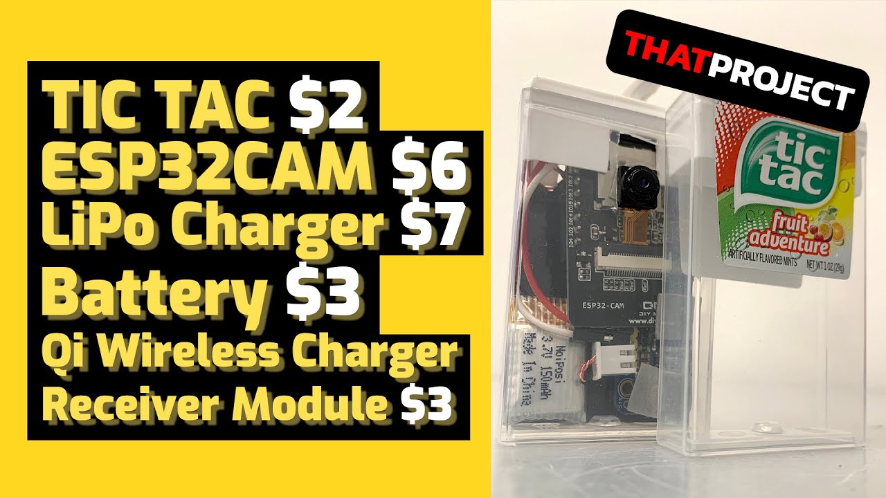
I made a tic-tac camera that can be easily taken out and used at any time using a tic-tac case. It's battery operated and charges the battery with wireless charging.
SD Card $? (You may have an sd card that is not in use.)
Tic Tac $2
ESP32CAM $6
LiPo Charger $7
Battery 3.7V 150mAh $3
Qi Wireless Charger Receiver Module $3
[ESP32TTGO - Battery ...
dry pelican
formal sand
After 2020 you basically have to buy your ics as you are designing your board. I...
Exactly. I found this TI "simple switcher" buck converter IC. Not sure about part number
elder peak
I've had really good luck finding Diodes Inc's switchers in stock. The problem is the datasheets are awful.
dry pelican
Peak chip shortage (this was actually taken yesterday)

Imagine waiting 2 years and 2 weeks for a part
 echo zephyr
 worldly schooner
Sounds about right.
distant raven
worldly schooner
Sounds about right.
At least some samd chips are back in stock
Digi-Key has a few thousand samd21g18a in stock currently
dry pelican
2021 was "um I can't even find an ina219 in stock in the small package"
A lot more are stocked than in 2021
But there is still shortage
woven bluff
and the raspberry pi...
formal sand
I remember having a client pay $28k for 150 ics that would have costed 1.2k....
Dark times....
distant raven
woven bluff
and the raspberry pi...
This is getting better
formal sand
Its so much better now
distant raven
I’ve seen more stock come through the last 2-3 weeks than the last 4-5 months
formal sand
Interesting
distant raven
Especially 4B
formal sand
What kind of ics have you seen that change on? Mcus?
distant raven
formal sand
What kind of ics have you seen that change on? Mcus?
Samd21
A number of STM32
Though I was referring to the raspberry pi SBCs with my statement about recent stock changes

Hackster.io
In interview with David Bombal, Raspberry Pi co-founder Upton has doubled down on predictions that stock improvements are coming soon.
 spice turtle
This is why I bought some dsPIC33CK's for a project I might want to do. Although I feel a bit of guilt knowing they might just sit there being hoarded
distant raven
spice turtle
This is why I bought some dsPIC33CK's for a project I *might* want to do. Althou...
I’ve found things are coming back in stock more often than before
I have been holding on to samd21e18a for a while. They’re pretty well in stock now though
spice turtle
You know, I looked into that series and it didnt have what I wanted. Same with STM32. I even looked into the newer PIC32 and they werent at the same price point as even the SAMD chips. I did want to give them a chance though, seeing as I have the programmer (PICkit)
On the subject of drivers:
I just bought this chip for a potential digital buck smps: MCP14628-E/SN
For boost stuff, Ive used two transistors and it seemed to work well.
rigid fiber
Is there a circuit that could take either the the D+ or the D- line from a USB port and split it into two, the one way goes to the ESP 32 chip as expected, the other way goes to a LED to make it blink, without corrupting the signal on the first half?
dry pelican
Buffer
Or a transistor
Don't really know if that would mess up the impedance somehow
But probably not
rigid fiber
By buffer do you mean a voltage follower with an op-amp?
supple pollen
That's one approach.
formal sand
rigid fiber
Is there a circuit that could take either the the D+ or the D- line from a USB p...
do you want it to blink when there is data transmission happening?
rigid fiber
formal sand
do you want it to blink when there is data transmission happening?
You got it. Blink on data transfer.
distant raven
That might be hard.. you’d be better of just doing that in firmware and blinking an LED like say the Adafruit Feather M4 does
dry pelican
yeah you would need to do it in software bc USB is differential
and one line might always be high or something
supple pollen
I think even when USB is "idle", it's sending clocking data back and forth, so the LED would always be partially lit
hushed smelt
Worked out in the end, It does not produce nearly enough light to be used as a workshop lamp. I would have been disappointed anyway.
supple pollen
I ended up buying a fluorescent fixture designed for warehouse lighting as a workshop lamp. 31000 lumens is indeed enough light.
hushed smelt
Oh I have overhead workshop lighting. I just wanted to fix a closer reticulating arm style work lamp. This would not have been a good replacement for that.
rustic linden
I have a bunch of LED ceiling lights I'm considering turning into a workshop lamp
hushed smelt
Yeah apparently cree is the way to go for stuff like this.
supple pollen
These things are a compact source of lots of light
 rustic linden
i have a wide range of lightbulbs, but I'm not sure lightbulbs are the best solution
hushed smelt
 supple pollen
LED vs induction: Thunderdome!
 hushed smelt
That's what I was trying to replace and ended up fixing the power supply issue.
At least the LED's and pcb design works. It's the only thing I didn't screw up with the whole project. :/
spice turtle
dry pelican
I found some I2C controlled synchronous buck boost converters a while ago
the challenge there is that most converters are in crazy packages like that. There are very few that arent QFN and are inexpensive.
To do it digitally, it broke down in the following way:
dspic33CK: $1.64 (SSOP)
Driver$2.00.
Total:3.64
(mosfets and passives are excluded in this since they are common to both circuits)
There was one that would fit the bill, and it came in slightly cheaper, which cost $2.84. There was a more expensive one (maybe higher frequency) that comes in at more than 77 cents more expensive than the digital version. There are some advantages of going digital imho 🙂
(
rigid fiber
supple pollen
I think even when USB is "idle", it's sending clocking data back and forth, so t...
That would be fine. I figured it would be kind of PWM-ish and get brighter and dimmer between idle and actual data transfer.
supple pollen
I suppose it depends on the modulation scheme. Perhaps I should get out an oscilloscope or an LED and buffer circuit and have a look.
It's some variant of NRZ (not return to zero) with bit stuffing to maintain synchronization
 lunar cosmos
Question - I have a 5v/3a supply on my board from a TPS54331. I followed the TI Webench for the design and component selection.
When I pull 3A, the voltage sags to 4.4v. Is there any way to keep it at 5v?
Also, I was trying to measure noise on the 5v rail with my oscilloscope, but I only read 150mv peak-peak, which seems kind of low. Can someone help me with finding the proper settings for measuring noise?
supple pollen
It could be your upstream supply is sagging. Curiously, noise measurements are normally limited to 20MHz or so.
rigid fiber
Are there any things out there for esp32-family QFN chips that you can just put in the QFN chip and tighten it in place without soldering, and it breaks out the pins, provides a USB port, and so on?
supple pollen
There are QFN testing sockets with spring loaded pins. You'd have to mount that socket onto a board that provided the additional connectivity
rigid fiber
cool
Somebody at the local maker, their employer is willing to let us tag along on an order to help get it over 10,000, but it means 200 chips for 5-10 people. But it's like half price for an ESP32-S3-WROOM-1-N16R2 compared just getting couple from Digikey or Mouser or LCSC.
supple pollen
I wanted a somewhat obscure chip for some breadboarding and I found a reseller that had 22 of them, but I had to buy all of them. I did, so I have spares, I guess.
hushed smelt
you would need a custom jig for the chip but that wouldn't be too much different from using a custom pogo pin or stamp setup.
making sure it's flat and making good contact on a flat surface seems like a harder problem to solve
supple pollen
That's what the testing sockets do, basically
 paper vale
Hello I want to measure phase currents of a BLDC motor to use in FOC. I'm finding the best method to adapt the signal for ADC. What is the best method between adding an DC offset and using an active rectifier ?
supple pollen
Sometimes it's easier to measure the current drawn by the motor driver, if you're looking to measure overall current. If you want to measure per-winding, it's somewhat more complicated than either an offset or rectifier. However, there are high-side current monitoring devices available such as https://www.adafruit.com/product/904 that might be useful

This breakout board will solve all your power-monitoring problems. Instead of struggling with two multimeters, you can just use the handy INA219 chip on this breakout to both measure both ...
supple pollen
Ah, those are better ideas
elder peak
..one might call them more au current
unreal flax
elder peak
..one might call them more au current
That joke is golden!
 tough matrix
what is everyone's favorite surface-mounted slide switch?
I used this one: https://www.digikey.com/en/products/detail/c-k/PCM12SMTR/1640125
but it is slightly too small for my taste
distant raven
tough matrix
what is everyone's favorite surface-mounted slide switch?
I used this one: https...
I’m a fan of this one: https://www.digikey.com/en/products/detail/AYZ0102AGRLC/1640121
tough matrix
seems to be almost same size, 7x3 mm
distant raven
Yeah, 0.5mm larger
But it is bigger so.. lol
There’s another one I’ve recommended before.. lemme find it. Do you have a size upper limit?
tough matrix
well, I guess anything over 20mm would be hard to fit
elder peak
I think that's about the biggest you can get in SMT, everything bigger is through-hole.
dry pelican
What is a good 5x5mm button? I found the brass ones, but I'm looking for the plastic ones that are on the circuit playground
supple pollen
Looking at the schematic on the learn guide, the Circuit Playground switches are marked "EVQQ". A quick web search reveals Panasonic offers an EVQQ switch line that looks like them. Here's one link https://www.newark.com/panasonic/evq-q2w03w/switch-tactile-spst-20ma-15v-pcb/dp/53W8284
distant raven
supple pollen
Looking at the schematic on the learn guide, the Circuit Playground switches are...
Granted, 6mm
Actually they’re both 6mm
I should have looked closer
I do chuckle though because I’ve had a tab open for those buttons for the last like.. 8 months
I’ve not ordered them but I have plans to eventually
dry pelican
Maybe I can find the same type of switch as a 5mm part
tough matrix
5 mm is unusual.
common size is 4.5x6mm
distant raven
I use these personally https://www.digikey.com/en/products/detail/R-667078/13232037

If you’re curious about how the size compares to say.. 0.1” mounting holes or 0603 LEDs
dry pelican
tough matrix
5 mm is unusual.
common size is 4.5x6mm
It seems you're right. The only ones I can find on Mouser are these brass buttons: https://www.mouser.com/ProductDetail/CUI-Devices/TS18-5-15-SL-260-SMT-TR?qs=tlsG%2FOw5FFh4WzqzrHrOOQ%3D%3D
woven bluff
I have a THT D-Sub connector with 68 pins. Would it be a good idea to cover the pins with solder paste and hot air to solder all pins at once?
worldly schooner
For most through hole connectors, you generally avoid this method due to the risk of melting the component you’re trying to solder. I can’t speak for your specific connector, but if you have the option to do it by hand, it might be safer that way.
You could check the data sheet for more detailed information on soldering curves for reflow, if they have any such data?
Or whatever the equivalent process for THT might be. Wave soldering…?
distant raven
worldly schooner
For most through hole connectors, you generally avoid this method due to the ris...
Under the right conditions, it actually wouldn’t put much more heat than typical THT soldering. But probably some trial/error to see how quickly it would need to be done. I don’t think it would introduce any more heat than wave soldering.
worldly schooner
A d-sub would be a lot more tolerant to heat compared to a plastic through hole header for sure. By how much, I wouldn’t know…
woven bluff
the idea of hand solder 68 pin frightens me
formal sand
68 pins ain't that bad, unless you have to do more than 1 board
If it takes you 5 seconds to do one solder joint, then it would be like 6 mins of soldering
You can use a solder melting pot to do it if don't have anything else on the other side
 upbeat zephyr
Altium CoDesigner is a thing
 elder maple
could someone recommend a good LTSpice tutorial?
dry pelican
Afrotechmods has one
 rigid plume
Hi, would anyone recommend an alternative SOC (not module) to the ESP32-S3, that has WIFI and BLE capabilities, and is roughly the same. Thanks.
unreal flax
rigid plume
Hi, would anyone recommend an alternative SOC (not module) to the ESP32-S3, that...
Would you consider other ESP32 variants, or do you want a different manufacturer entirely?
 icy atlas
Currently usingthese devices with pico pi
https://www.adafruit.com/product/157
https://www.adafruit.com/product/389
but the IR sensor always has inconsistent results. When pressing a button twice it always has like one pulse duration that is waaay different from the other press. Anyone know what could be causing this?


IR sensor tuned to 38KHz, perfect for receiving commands from a TV remote control. Runs at 3V to 5V so it's great for any microcontroller.To use, connect pin 3 (all the way to the right) ...

This little remote control would be handy for controlling a robot or other project from across the room. It has 21 buttons and a layout we thought was handy: directional buttons and number ...
supple pollen
Could be the pause between pressings
icy atlas
The docs on the site tell you to check for button pressing by comparing to a know pulse for the button with x% fuzziness
How should I do this when I get such varied results
 tidal elbow
My SMD components keeps failing. The decoupling caps shorted to GND, Pull resistor for reset pin acting funny (no voltage, and resistance value changed everytime pcb is powered). Am I just need to find better components supplier? or my PCB design need another redesign?
Any advice please...
rigid plume
unreal flax
Would you consider other ESP32 variants, or do you want a different manufacturer...
Totally different manufacturer, due to security concerns.
supple pollen
tidal elbow
My SMD components keeps failing. The decoupling caps shorted to GND, Pull resist...
For the resistor, I would suggest probing the voltage on the component itself to check for good connectivity between the component and the board. If that is bad, it could be a problem with the solder joints themselves, which could be an assembly problem, a board design problem, or a mechanical problem (heat, flexing, or vibration putting stress on the joints). For the capacitor, if it's a tantalum capacitor, this is a known failure mode if the voltage has even a tiny excursion (in time or voltage) above the capacitor's rating (this sometimes happens during power-on while voltages stabilize). If it's a multilayer ceramic capacitor, this is a known failure mode, especially for lower voltage and higher capacitance ones, due to the microscopic thinness of the internal layers. I would also suggest unsoldering and inspecting the capacitor itself: after unsoldering, is it still shorted? If so, you do have a capacitor problem. If not, it could be a soldering or board problem.
woven bluff
if board space is limited, would it be better to put a zener at the input or output of a SMPS?
dry pelican
Output unless you need to protect input from transients
woven bluff
I always put SMPS behind a load switch
I also put a large tantalum at input, if I downgrade to 1815 or 2220 ceramic may be I can stick an input zener there.
supple pollen
Be wary of high capacity ceramics, they can have large voltage coefficients
woven bluff
I usually use more than twice the voltage rating than the actual working voltage
also I only use x7r or better
it's better to overengineer than deal with problems later
paper vale
Hello. I am working on a project to control a brushless motor using field-oriented control. I want to implement the speed and torque control but for that I need to generate the reference speed according to the voltage created by a potentiometer for example. What method can I use to get the reference speed according to the voltage created by the potentiometer?

I want to create the speed and Iq refs
spice turtle
By using an analog to digital converter, and then using a microcontroller to adjust the the speed. There are also dedicated IC's that will do the whole thing for you, but are kind of limited in current.
supple pollen
By reference speed, do you mean something like a reference frequency? There are voltage to frequency converter chips like the classic LM331 and others.
paper vale
supple pollen
By reference speed, do you mean something like a reference frequency? There are...
Not frequency. I want a way to deduce the speed from the voltage outputs from pot
for example 0V to 0 RPM and the max 5V to the max 370 motor RPM
supple pollen
Ah, that's more of the opposite conversion, frequency to voltage
rigid plume
unreal flax
Would you consider other ESP32 variants, or do you want a different manufacturer...
What would you recommend that is not manufactured by espressif? Thanks
dry pelican
There is already an simpleFOC projecy
unreal flax
rigid plume
What would you recommend that is not manufactured by espressif? Thanks
I don't have a great recommendation offhand, since Espressif is pretty dominant in this space, though Cypress I believe has some WiFi SoCs too.
rigid plume
unreal flax
I don't have a great recommendation offhand, since Espressif is pretty dominant ...
Thanks
 timid dove
Hey folks. I’m designing a component that needs to be mated via pogo pins. I’d like to use circular contacts (rings) for mating… but I don’t know what they are called, or how to find them. I’ve attached a picture, that better explains what I’m trying to do. Any thoughts on where to find the parts? Note… I’m also thinking designing the “rings” directly on a PCB with ENGR finish.
 supple pollen
Normally the mating contact would not be circular, just have a contact for each radius, so it will connect with the circular piece at any angle
timid dove
supple pollen
Normally the mating contact would not be circular, just have a contact for each ...
Not 100% following; you’re suggesting that I have multiple mating contacts and restrict the mating orientation options (e.g design the “dock” to be a square or triangle or hexagon shape)
supple pollen
No, just suggesting two contacts, and not restrict the orientation
Like slip ring contacts https://www.grandslipring.com/wp-content/uploads/slip-ring-contacts.jpg.webp
 timid dove
Got it…. I’m struggling to find the “rings”. I can’t seem to find them though the normal channels (digikey, mouser, etc). Do you know if there is an smt (or through hole) part that exists? Or is it as simple as designing a circular contact on my pcb (and having it plated)?
Hopefully that question makes sense
supple pollen
Oh, I misunderstood, I thought you were trying to design a connector that mated with the rings, you want to replicate the functionality of the rings. Yes, you fabricate that as a PCB (specify "hard gold" for them if you want them to be more durable). You can also just use metal rings and attach them to whatever.
timid dove
Sweet! Thanks
spice turtle
paper vale
for example 0V to 0 RPM and the max 5V to the max 370 motor RPM
You could read the voltage, convert it to digital, then use the SCALE function on an arduino and then output it somewhere. But generally to read speed, you need a tach
hushed smelt
I need that for my tank turret. I want it.
supple pollen
The slip ring assembly? https://www.adafruit.com/product/736

With a slip ring assembly, your electronics can now twist and turn safely. Add wheel encoders, 360 degree sensors, rotating LEDs, rotors and more! We've seen a lot of people DIY slip ...
distant raven
supple pollen
The slip ring assembly? https://www.adafruit.com/product/736
Using these is a… slippery slope
 hushed smelt
Found some micro slip rings. That should do nicely for adding the pan/tilt mechanism on top of the turret. 360 turret and pan/tilt camera.
tough matrix
timid dove
Got it…. I’m struggling to find the “rings”. I can’t seem to find them though t...
check mill-max catalog
https://www.mill-max.com/
Since 1971, Mill-Max has been manufacturing and designing high reliability precision-machined interconnect components & is a recognized global leader.
Order our print catalog or download the PDF straight to your device.
in particular, "target connectors/target disks"
most of them are available on digikey
tidal elbow
supple pollen
For the resistor, I would suggest probing the voltage on the component itself to...
Noted. I found no issue with the solder work, I'll check the caps value next. TBH this issue fixed when the failed components is replaced. But it'll happened again after 1-2 day 😤😩. I source the components from local online market place, that's why I feel like finding better reliable components supplier.
dry pelican
tidal elbow
Noted. I found no issue with the solder work, I'll check the caps value next. TB...
Maybe a voltage or overload issue
What is the circuit?
 twilit crane
Hey folks - using:
- adafruit 64x64 matrix panel
- adafruit rgb matrix hat + rtc for rasp pi
- raspberry pi 4 (running rasp pi Debian 11)
I’ve assembled everything per the instructions and got it connected and running some of the included demos, but am running into an issue where the images are distorted or text just won’t show up (e.g running example-text demo)
Any ideas what might be causing this?
dry pelican
Loose connections?
twilit crane
The cable to it seems to be well seated; or do you mean the soldering?
Could this be due to power shortage or the lack of clock battery?
dry pelican
Not lack of clock battery. But power supply issues can cause weird effects
hushed smelt
Attempting to run it from the microcontroller board power only will produce only red LED’s because it doesn’t have enough current for green or blue. Unless your code is specifically only red in color it means you’re not getting external power to the matrix properly. Ask me how I know. 😅
All red led’s instantly equals no external power to me.
twilit crane
Thank you! I was wondering about the all red on the default demo
Looks like my power supply is not good enough; will need to order one
 sick geyser
rigid plume
What would you recommend that is not manufactured by espressif? Thanks
sick geyser
rigid plume
What would you recommend that is not manufactured by espressif? Thanks
Pico W or just the wifi chip it uses Infineon CYW43439
woven bluff
anyone worked with GM counter? how small is the current transient when a particle hits the GM tube?
I'm thinking about instrumentation amp connected as transimpedance at low side of the GM tube
tidal elbow
dry pelican
What is the circuit?
 tidal elbow
dry pelican
What is the circuit?
tidal elbow
dry pelican
What is the circuit?
Pull up resistor for I2C, reset pin resistor, and vcaps capacitor was busted
dry pelican
tidal elbow
Pull up resistor for I2C, reset pin resistor, and vcaps capacitor was busted
That is very weird and should not happen. Especially those resistors. They're barely passing any current. The resistors short after a few days right? And this is powered on or powered off?
distant raven
tidal elbow
This bothers me..

I don’t necessarily think this is a good idea
I’d remove the R206 and the LED
woven bluff
if you want indicator, better use a driver, BJT, FET, etc
distant raven
Yeah, I worry if the pull up is failing that the 100 ohm resistor is going to over draw the pin and do damage.
You’re also making a voltage divider on the data line which is also not good.
tidal elbow
distant raven
You’re also making a voltage divider on the data line which is also not good.
You mean the resistor on the top of the optocoupler?
tidal elbow
distant raven
The i2c SDA line
The R205 is a pull up resistor. This is 4 layer PCB. While the R206 is bothersome, I'll try to DNP the indicator all together tomorrow.
Thanks for the suggestion 😊
tidal elbow
dry pelican
That is very weird and should not happen. Especially those resistors. They're ba...
After 2 days of on and off. It's not running continuesly for 2 days
supple pollen
woven bluff
anyone worked with GM counter? how small is the current transient when a particl...
It's pretty small, even after the electron multiplication takes place, you're taking about thousands of electrons, which is not much current at all
woven bluff
how does the circuit usually work? a general purpose amp on the low side followed by a comparator?
timid dove
tough matrix
most of them are available on digikey
thanks for the suggestions. Unfortunately, they don't have the exact shape that I'm looking for. I'm specifically looking for two nested rings (one inside of the other). Gonna follow madbodger's advice and make the ring on the PCB (ideally with Hard Gold - which doesn't seem to be an option for most cheap/prototyping PCB manufacturers).
hushed smelt
maybe electroplate it but that seems like a lot of specialized setup for 2 rings.
supple pollen
woven bluff
how does the circuit usually work? a general purpose amp on the low side followe...
Usually a capacitor to couple the pulse into some sort of amplifier/clipper/limiter
tough matrix
timid dove
thanks for the suggestions. Unfortunately, they don't have the exact shape that ...
PCBWAY has hard gold option
but it is quite expensive
formal sand
What about using solder above the copper basically like tinning the whole circle? There might be issues with oxidation of the solder but might be a cheaper solution
 cinder grail
supple pollen
The slip ring assembly? https://www.adafruit.com/product/736
cinder grail
supple pollen
The slip ring assembly? https://www.adafruit.com/product/736
https://www.adafruit.com/product/1196 more wires

With a slip ring assembly, your electronics can now twist and turn safely. Add wheel encoders, 360 degree sensors, rotating LEDs, rotors and more! We've seen a lot of people DIY slip ...
idle python
before i buy the pcb and components, can anyone double check if this will work as intended? i dont want to waste 62 dollars on a possibly not working board


min clearance and trace width is 5mil
 native plover
I want to pulse a solenoid with a Pico. I want to wire it like this and use twelve AA cells (either alkaline or NiMH) to power it. Does that sound reasonable?

I'm thinking that this might draw too much current from the cells or that the power might get a bit unstable for the Pico
Would it make sense to use twice the amount of cells to drop the voltage from higher up? That should reduce the current through the cells.
dry pelican
Use a mosfet instead of a bjt
It would probably work
But the current is really high
3.7A
Really high for what I expect from a solenoid
Power instability could be solved with a lot of capacitors
But idk if aa batteries can handle 3.7A
native plover
Yeah, it's a fairly chunky solenoid 😉
I tried smaller ones, but they lack the punch I need
Would it suffice to put one large capacitor on the Pico's input?
I was hoping that the relation between Vin/Vout and Iin/Iout on a buck converter is somewhat anti-proportional, i.e. the higher I raise the input voltage, the lower the current that has to go in
supple pollen
I'd probably put both a capacitor and a decoupling diode so the solenoid can't pull power from the Pico's capacitor
native plover
supple pollen
I'd probably put both a capacitor and a decoupling diode so the solenoid can't p...
Where would I put that? Before the 3.3V buck converter, and then the capacitor behind it?
 vast flume
Hey guys
I think I made (another) oopsie on (another) one of my pcbs, but I think this one is easily fixable
So I have this setup for a buck converter

But I forgot that the input voltage is ~13v, and since I'm feeding that directly into the enable pin (through a resistor to limit the current), I'm still sending around 7v to that pin
But in the datasheet it says the max voltage for that pin is 6v
I tested the pcb and the converter doesn't power on. Wouldn't be supprised if I fried tf out of it when I first plugged this in. I have another one though so I was wondering if anyone had a possible solution in mind?
Could I just use a resistor with a higher value?
spice turtle
The datasheet shows a 100k resistor on the enable pin. It looks like you got that
It also shows a voltage of 4.75V to 23V, so your input of 13V is fine
If you have a scope, check the SW pin for a waveform.
Otherwise, id look for any shorted pins. Unless you got the package wrong, I dont see anything wrong with the above schematic
vast flume
Hmmm good point
Sadly I don't have a scope with me
No short on the board though, put a continuity tester across the + and - terminals and didn't get anything
spice turtle
make sure your pins are actually on the board. With SOIC its easy. Sometimes a pin Looks like it connected but its not
vast flume
Honestly that could be it
All the components on this board I pulled off of the previous version of this board
spice turtle
You could also just hit it with a air gun to make sure.
spice turtle
not too much though
vast flume
Yeah 🤣
spice turtle
I have just hit the pins with a hot iron and a tiny amount of solder and it was ok
vast flume
Heres how it looks rn


 spice turtle
is it IC1?
vast flume
Yeah
spice turtle
I can already tell by looking at it you have unsoldered pins
and Pin 3 (Im assuming its pin 3) needs solder
pins 1 and 2 look iffy at best
Id touch up all the pins
vast flume
Laziness strikes again lol
Just added some more solder will report back in a min
We have light 🎊

That fixed it 🙂
Now I just have to figure out whats up with the 3.3v bus lol
spice turtle
sweet
spice turtle
vast flume
Now I just have to figure out whats up with the 3.3v bus lol
probably the same. If its a regulator it may not be connected. Those large pads take A LOT of heat
I have to put my iron on its side a tad to get full contact.
spice turtle
between 3.3V and gnd?
vast flume
Yea
U4 wasn't it
Ok this just got confusing. I cleared the short, but now the inductor in the 5v buck circuit is getting really hot each time I connect it, and the 3.3v linear regulator is just outputting ~0.05v
But theres no longer a short between 3.3v and gnd
spice turtle
theres something pulling a lot of current.
Whats your 5V at?
I would disconnect the 3.3V regulator to make sure your 5V line is ok
 spice turtle
its more or less for filtering. Some regulators dont like it but you'll know right awya
vast flume
Thats true
Idk what to even check at this point
The microcontroller is soldered perfectly
And I don't think u8 and u4 were the cause
But I have no idea what else could cause this bc everything else is so straightforward
spice turtle
the regulator might be bad if you are using used parts
vast flume
The 3.3v one?
spice turtle
yea
spice turtle
desolder it and connect wires to it pretty much.
spice turtle
basically dead bug it
spice turtle
you have an issue down stream of the 3.3v taking up a lot of current then
vast flume
Yeah
spice turtle
If you have the 3.3V removed does the inductor still heat up?
spice turtle
it shouldnt heat up with no load unless its a really really awful inductor
vast flume
Strangely it does...
Uh oh
The confusing thing is I use this same inductor for the regulation circuit on a different pcb and it works well
But then again this is 14v-5v and the other circuit was stepping up to 5v
spice turtle
your using a 10uh inductor, right? Rated for 4A?
spice turtle
vast flume
Strangely it does...
check C15 and C16 (the output caps)
a scope would really come in handy right now lol
vast flume
Yeah that would help a ton 🤣
How should I check them?
Just see their voltage?
Or make sure they're connected
vast flume
I tried both 😭
vast flume
I don't have a variable supply 😦
dry pelican
Current is the important part
vast flume
Yeah
dry pelican
Multimeter can also
vast flume
dry pelican
Do you know how much current the buck uses unloaded as well?
Not sure
vast flume
dry pelican
Do any caps heat up?
I'll check
dry pelican
And you may be able to also use your multimeter to measure AC current through tge inductor
Well since it's heating, it's obviously drawing too much current
And what buck IC?
vast flume
0.25 amps is the current draw that I just measured
vast flume
dry pelican
And what buck IC?
MP2307
Also just checked and at least one of the caps is heating up
C15
vast flume
Yeah
vast flume
22uF
dry pelican
Add some smaller ceramics in parallel
Like 0.1uF
Larger values usually have more esr and esl
vast flume
Ok
in parallel with the current one?
Added a 0.1uF in parallel to both c15 and c16 (the output caps)
Still gets incredibly hot 😦
supple pollen
native plover
Where would I put that? Before the 3.3V buck converter, and then the capacitor b...
I don't have the circuit in front of me, but as a guess, supply to diode, then capacitor, then buck converter
formal sand
Have you tried desoldering the cap?
native plover
I see, thanks!
 balmy tide
Can i use cat6 ethernet cable to transfer mipi signals? I am using MIPI retimer IC from TI and I need to move and swap some pairs in in between devices/connectors. Mipi requires 100 ohm differential impedance which cat6 cable has and with cat 6 I believe I can swap how rj45 jack wired to swap pairs around without needing to use vias on the board
 cursive sentinel
Should be able to, although it's difficult to say how far you can run it.
balmy tide
Retimer thing tested with 30cm on fr4 board as long as I can match that it's golden
 neat raft
Hello, I have built a circuit with the QT PY and wanted to see how I could replace the dev board with an RP2040 on a PCB to replace the MCP23017s with the RP2040s GPIO pins. Using the "Hardware design with RP2040" I have built the minimal circuit required and hooked up the GPIO pins to the rest of my circuit.
Long story short: I have seen that the GPIO pins were connected to header pins as well as being connected to ground for a general purpose dev board design. Should they be connected to ground in addition to my other circuitry which mainly consists of a 32 pin header for game cartridges?
supple pollen
I'm unsure why you would ever hardwire GPIO pins to ground. It seems like asking for trouble.
 exotic oak
I'm wondering if with the circuit playground express, is it safe to have it plugged into USB at the same time a AAA (alkaline) battery pack is attached or if I need to make sure to always turn off the battery pack first so it doesn't try to charge it?
neat raft
supple pollen
I'm unsure why you would ever hardwire GPIO pins to ground. It seems like askin...
It also struck me as a bit weird. btw I am referring to this particular part
 supple pollen
Ah, that has them going to two-row headers, where one row is the grounds, and the other row is the signals, so you can pick up a signal and ground from two adjacent pins.
supple pollen
exotic oak
I'm wondering if with the circuit playground express, is it safe to have it plug...
Yes, it's safe. The Circuit Playground Express does not include a battery charging circuit, just steering diodes, so it can be powered from either USB or the battery connector, without backfeeding power from one to the other.
neat raft
Thank you for clearing that up. Now it makes much more sense.
exotic oak
supple pollen
Yes, it's safe. The Circuit Playground Express does not include a battery charg...
Ahh thanks. I had been using feathers that had charging and had just assumed the express did too apparently. Oops.
rustic linden
supple pollen
Ah, that has them going to two-row headers, where one row is the grounds, and th...
i thought that was the case
 broken zenith
Is there a simple way to toggle a relay's state (on to off, off to on) every 200ms? (I have a very specific need for a relay and not a transistor of any kind) I plan to use the EE2-24NUH if that makes a difference. I'm looking for something involving cheap timer ICs or an RC circuit, so no microcontrollers ideally. Thanks!
 unique patio
broken zenith
Is there a simple way to toggle a relay's state (on to off, off to on) every 200...
unique patio
broken zenith
Is there a simple way to toggle a relay's state (on to off, off to on) every 200...
NE555 timer is classic and can sink up to 200mA at up to 15V. But the EE2-24NUH uses 24V coil voltage. Can you pick a relay with a lower coil voltage?
broken zenith
Oh, I didn't realize that. I'm just looking for a physically small SMD signal relay, can you recommend any? Thanks for the help
unique patio
what voltage and current are you switching? What supply voltage is available/convenient?
broken zenith
This is gonna sound crazy but the voltage and current switching capacity don't matter. 3.3v is the planned supply voltage, but I could increase that if need be.
unique patio
don't matter, do you mean you just want a click noise?
are you not switching any voltage? Is it an input, like a touch input or something?
broken zenith
The click and the tactile feeling, essentially. This is the E-Fidget Lite, so I'm just using the relay for haptic feedback.
unique patio
ne555 is 4.5V minimum. It could drive any small relay. But you want to pick a relay based on clickiness, then. Did you try the relay in question already?
broken zenith
Nope, but that might be a good idea. I've got a relay with a good click to it, let me check what it is
unique patio
you could use a latching relay and reduce the power consumption

BZZZZZZZZZZ Feel that? That's your little buzzing motor, and for any haptic feedback project you'll want to pick up a few of them. These vibe motors are tiny discs, completely ...
[not a relay, but might feel satisfying with a pulse]
broken zenith
Hmm, I hadn't thought of that! thanks. The relay I've got is a SRD-05VDC-SL-C.
I used vibration motors in the last version, and they were pretty good, but I want to try something new.
unique patio
more modern 555-style ic: https://www.adafruit.com/product/5222

According to The Internet, 95% of electronic projects can be done with an op-amp or 555 timer chip. We're not so sure about it, but the 'triple nickel' (as we like to call it ...
digikey sells 1000's of small relays, buy a few maybe and see how they work otu
broken zenith
As for the 555 - What's a good resource for learning how to get that to do what I want? I saw the Adafruit learn guide but it seems like more of an overview than an in-depth tutorial.
unique patio
The 555 is so common that there are thousands of tutorials. Books with examples include Make:Electronics and the Art of Electronics
this seems pretty thorough: https://learn.adafruit.com/getting-to-know-the-555
is that the one you mean?
broken zenith
Yes, but I guess I thought wrong! Taking a second look it seems pretty good. I would want it in astable mode right?
unique patio
yes
broken zenith
Alright, I'll do some reading. Thanks for the help!
unique patio
yw!
 raw thorn
Relays can be wired as a buzzer & timing altered with capacitors & resistors.
idle python
idle python
before i buy the pcb and components, can anyone double check if this will work a...
can anyone help me with this pls?
distant raven
idle python
can anyone help me with this pls?
It would be easier if you shared your files zipped up so everything can be evaluated
dry pelican
I would say it looks fine. A good tip for final verification is to print it out (only soldermask and silkscreen) on a paper printer to see how it will look irl
 left citrus
hey guys i want to interface a 1.8V SPI Device (ICM20948) and use a level shifter with my MCU (3.3V) : commonly BSS138 is used, but due to footprint restrictions i want to find alternative; i believe RE1L002SN might be the right equivalent, can anyone help me out to confirm ?
supple pollen
BSS138 is normally used for I2C style communication, not SPI. You'll want a different kind of level shifter.
There are a bunch of choices out there, such as the SN74AUP2G34, which includes two level converters and is available in an SC70-6 package (two of them would handle SCLK, MISO, MOSI, and CS)
left citrus
i assumed it would BSS138 as it has been used on Adafruit ICM20948 module:
https://learn.adafruit.com/assets/93864
supple pollen
It looks like that chip supports both SPI and I2C. The AdaFruit board appears to use it in I2C mode. Since you specified SPI, I figured you wanted to use it in SPI mode.
left citrus
The adafruit board does support SPI, but i think i'll stick to dedicated level shifters, thanks alot
cursive sentinel
The BSS138 shifter is usable for I2C without hurting performance too much (as long as you stay below 400kHz) since it is an open drain interface. SPI is entirely push-pull and typically run at significantly higher clock rates than I2C and no bidirectional signals, so you really do want an IC level translator.
left citrus
I figured NTS0104 might be the IC with 4 channels
on the datasheet it says: Push-pull: 50 Mbps
cursive sentinel
That should work assuming it supports the voltages you need.
Although keep in mind that one of your channels needs to go in the opposite direction of the others.
left citrus
i have no clue what mosfet sparkfun is using, but thier breakout works on my breadboard prototype
 cursive sentinel
Pretty sure it's the BSS138
supple pollen
It's a lot better than the popular 2N7000 for 3.3V logic, and acceptable even for 1.8V logic
 cursive sentinel
The 2N7000 is unsuitable for 3.3V logic.
supple pollen
I agree, but it's commonly used as if it were suitable, unfortunately
woven bluff
I often avoid old parts... like xNxxxx
 grand fossil
I think this is the right place to ask -- for Eagle if I wanted to place a 2.0mm 4 pin JST connector (like the stemma ones) what should I look under for the part? I was able to find the 3 pin ones in the adafruit eagle libraries but having trouble finding the 4. My first time with eagle so a bit of a novice.
hushed smelt
The smaller ones are JST-SH and the bigger 2mm ones are JST-PH
@grand fossil https://www.adafruit.com/product/4390

Designing boards with plug-n-play connectivity is a snap, with STEMMA connectors. Here's a pack of 10 of our favorite 2mm pitch connector - which are compatible with the JST PH ...
grand fossil
hushed smelt
<@690577573020696659> https://www.adafruit.com/product/4390
I mean for the eagle design component placement for PCB design -- trying my hand at a custom board. Was able to find the 2 pin and 3 pin ones there but I may be missing something with the 4.
 hushed smelt
Are you asking for a footprint?
grand fossil
Yeah -- wasn't sure if there was a specific component I should use when placing a part for a jst 4 pin 2mm.
hushed smelt
The product page has a link to the manufactures website where the blueprints are for creating your own footprint. If you want something premade that you can drop in I recommend finding a product that already uses it, go to that Adafruit's product page, find the downloads for .brd and .sch and snag it from there.
grand fossil
Sounds good, will give that a go, thank you.
hushed smelt
Do you know of an Adafruit product that uses the connector you want to use?
hushed smelt
The .brd and .sch are usually in the learn guide for a product. So you'll want to go to the product page, scroll to the bottom, find the learn guide associated with it, find the downloads link in the learn guide.
stemma is JST-PH, stemma qt is JST-SH.
@grand fossil The stemma soil sensor has one. https://github.com/adafruit/Adafruit-STEMMA-Soil-Sensor-PCB
It uses a JST-PH connector. How you'll separate the component in the .brd and .sch file and get them into your project is up to you. 👍 I don't use Eagle so I can't offer more specific advice.
cursive sentinel
hushed smelt
It uses a JST-PH connector. How you'll separate the component in the .brd and ....
don't use eagle
You included the advice in saying you can't offer advice 🤣
grand fossil
Sounds good, it's good advice for the future re: digging into the product page there for the brd -- will definitely do that. Was able to find a library with a 2mm one so should be set.
 compact frigate
Which pins of the RP2040 can sdioio use? Are some pin combinations (including their order) slower than others or even impossible? Or might sdcardio be faster than 4-pin sdioio on the RP2040?
cursive sentinel
Generally speaking on any microcontroller there won't be pins that are slower than others unless you are doing something you shouldn't (such as remapping the reset pin as a GPIO).
compact frigate
cursive sentinel
Generally speaking on any microcontroller there won't be pins that are slower th...
Often SPI is faster than bitbang, but requires specific pin combinations. So if sdioio is faster than sdcardio with SPI, then maybe sdioio also does something special under the hood and requires specific pins for reaching maximum speed.
cursive sentinel
Those are both hardware peripherals, so neither would rely on bit banging. I'd have to look at the datasheet for specifics which I can't do at the moment.
 opal rune
I believe it's because those are the QSPI pins that the flash memory uses, so I don't think it's usable for sdioio, unless they're free. Though according to https://learn.sparkfun.com/tutorials/rp2040-thing-plus-hookup-guide/all and the datasheet, the pins are:
Pin 52: CLK
Pin 56: CS
Pin 53: DATA 0/DI
Pin 55: DATA 1/DO
Pin 54: DATA 2/WP
Pin 51: DATA 3/HOLD
grand fossil
(Just deleted and reposted after fixing an issue I noticed, apologies).
Would it be possible if someone has a chance to get a second set of eyes on my pcb I was hoping to have printed out? No rush of course or expectation. I'm relatively new with electronics and pcb design in general so in case I've done something terrible.
An attempt to make my dumb RGB mouse bungee smarter.
Elements:
- Emulates the form factor of the existing board such that it'll still fit (I had to extend the top a bit so the WS2812B-mini would still clear the weights which sit under the board on the bungee
- Add the ability to extend the bungee with i2c in the future to support additional sensors
- Have the ability to control additional light strips in the future from the same d1 mini (small light bars, nothing large given the current needs)
- Support the existing button 6x6x15mm from the bungee because the cutout in the frame exists for it anyhow
Considerations taken:
- Each light strip and the light square have a 1000 uF capacitor across their VCC to GND prior to their connections to smooth out the voltage from spikes and associated noise
- The LED data lines also have a 470 Ohm resistor
- There's a 10k Ohm pull up resistor for the button
- The button also has a 1uF debounce capacitor
- Have mosfets setup for the stemma sda and scl lines and a 4.7k Ohm pull up resistor for the 3.3v to 5v signal lines
Apologies for the rough nature of this - was my first eagle project so still learning. I haven't sorted out how to make it look nice with all the different sections yet. I did sort out the way to map up the different net lines though so it shouldn't be too hard to parse.
Main elements are:
- On the right I have the WS2812B-minis
- Connected to those other two GPIOs on the right (located above and below on the schematic) I have the JST connectors setup for those LED strips
- On the bottom left I have the stemma connector setup for i2c
- Button on left
- JST 2 pin connector for power top left
 supple pollen
grand fossil
(Just deleted and reposted after fixing an issue I noticed, apologies).
Would it...
supple pollen
grand fossil
(Just deleted and reposted after fixing an issue I noticed, apologies).
Would it...
You may have the level shifter MOSFETs in backwards, depending on what the expected voltage of the external I2C bus is
unreal flax
grand fossil
(Just deleted and reposted after fixing an issue I noticed, apologies).
Would it...
The capacitor on the button looks problematic, because it's blocking the path to GND instead of being in parallel with the signal. Also your MCU would probably appreciate a local small decoupling capacitor on its power pin.
grand fossil
Thank you for taking a look. Will take a look into those issues.
grand fossil
Apologies, could someone take a once over of my logic here? I'm going to order some mosfets to try things out with a proto board prior to ordering a custom pcb just want to make sure I understand the concept fully.
The long line at the bottom there is the gate and then the other goes from source to drain (more speaking out loud in case my thinking or understanding is off here), the 4.7k ohm resistor is a pull up resistor on the MCU's pin keeping it in the high state normally (as needed for i2c), the gnd here is the source, drain is the SCL load. The MCU's pin's signal acting as the gate in this case causes the 3.3v signal to be emulated by the 5v line (high when high, low shutting off the flow when low) so I think my logic is sound with my latest change here attached. Is that correct?
Really appreciate the assistance.
 grand fossil
Adjusted those other issues, ty. I had read about adding the button debounce when looking into potential gotchas I should address, added the capacitor, and completely blanked putting it in series vs in parallel.

 unreal flax
grand fossil
Adjusted those other issues, ty. I had read about adding the button debounce whe...
unreal flax
grand fossil
Adjusted those other issues, ty. I had read about adding the button debounce whe...
The button cap is still a bit weird, since you have both sides of it shorted together to ground. You want it on the other side of the switch, like this sort of arrangement:
 grand fossil
unreal flax
The button cap is still a bit weird, since you have both sides of it shorted tog...
grand fossil
unreal flax
The button cap is still a bit weird, since you have both sides of it shorted tog...
Ah I see, that makes sense. So the button debounce is when the button is depressed it doesn't send additional input signals during that period of time when things are returning to the normal state. When the button is pressed it becomes low but once it comes up it's high again. Without the capacitor as the mechanical aspects move it would flow to low potentially for a brief moment but by having the capacitor it ensures once the button is depressed it immediately reads high again as it smooths the voltage avoiding those random fluctuations. Is that right? That's why it's on that side as if it was on the other side it wouldn't do anything in this case?
unreal flax
Yeah, the capacitor "holds" the voltage steady for a short time even if the switch is bouncing open and closed, so you get a smoother, slower transition which looks like only one low-high or high-low change to the input pin.
grand fossil
Awesome, ty. Makes sense. Will give this a try with a breadboard once I get the parts and give it a go. Really grateful for the assist.
cursive sentinel
compact frigate
Often SPI is faster than bitbang, but requires specific pin combinations. So if ...
In the datasheet I'm not seeing any interfaces dedicated to SDIO, unless it is implemented with PIO. Where are you seeing info about it?
 waxen halo
Hi I'm taking my first attempt at creating a DC-DC power supply and I'm really struggling trying to be sure of my mosfet selection and what the thermal limits are. I'm using the MIC2169BYMME synchronous step down switching regulator. The datasheet states:
For applications where Vin < 5V, the internal Vdd regulator operates in dropout mode, and it is neccessary that the power MOSFETs used are sub-logic level and are in full conduction mode for Vgs of 2.5V. For applications when Vin > 5V; logic-level MOSFETs, whose operation is specified at Vgs = 4.5V must be used.
I'm struggling to interpret this. Does that mean that for my 12Vin, Vgs th must between 4.5V and 5V? Or just that it's at-most 4.5V?
woven bluff
the chip operates at 5V, if you want to minimize heat, you'll need a FET with Vgs(Rds->min) < 5V
waxen halo
As in it doesn't matter what the upper limit of Vgs is, just that I need to judge it by the specifications for Vgs being 4.5V? So like if a mosfet says something like:
Rds(on) max:
0.0087 at Vgs = 10V
0.0135 at Vgs = 4.5V
I might want to look for something else?
I think I'd been thinking I needed to be thinking of these mosfets at 12V, but that seems clearly wrong now. Vds would be 12V, Vgs would be 5V.
compact frigate
cursive sentinel
In the datasheet I'm not seeing any interfaces dedicated to SDIO, unless it is i...
Thank you for looking into this. https://datasheets.raspberrypi.com/rp2040/hardware-design-with-rp2040.pdf says "The constraints our SD PIO software puts upon us is that the four data signals must be connected to contiguous GPIOs. The CLK and CMD signals can go anywhere." Does sdioio use PIO with the same constraints? Would some pin combinations (within these constraints, or beyond them by changing the PIO implementation) work faster than others?
woven bluff

GitHub
Contribute to raspberrypi/pico-extras development by creating an account on GitHub.
cursive sentinel
compact frigate
Thank you for looking into this. https://datasheets.raspberrypi.com/rp2040/hardw...
The reason that constraint exists is likely due to the fact that they are using side-set, no pins will be noticeably slower.
Regarding sdcardio and sdioio: those are Adafruit libraries. It looks like sdcardio uses SPI while sdioio uses SDIO.
SDIO will be faster.
compact frigate
cursive sentinel
Regarding `sdcardio` and `sdioio`: those are Adafruit libraries. It looks like `...
Does sdioio also use PIO and specifically PIO "side set" on the RP2040? If so, does it have the same constraint (contiguous GPIOs)? If not, PIO "side set" wouldn't work noticeably faster, right?
If sdioio requires using contiguous GPIOs on the RP2040, can their order be inverted, for example GPIO 22,21,20,19 instead of 19,20,21,22?
cursive sentinel
compact frigate
If `sdioio` requires using contiguous GPIOs on the RP2040, can their order be in...
You could probably change the order by editing the PIO assembly, but side-set always requires contiguous pins. I'm not familiar with Adafruit's implementation, but as a general rule SDIO is the 'native' interface for SD cards. SPI is really just the 'fallback' interface. It's slow in comparison, but everything can support it.
compact frigate
cursive sentinel
You could probably change the order by editing the PIO assembly, but side-set al...
So sdioio might be implemented with PIO or run on the main processor, we don't know, right?
cursive sentinel
Ok let me find the code...
compact frigate
cursive sentinel
You could probably change the order by editing the PIO assembly, but side-set al...
Regarding "side-set always requires contiguous pins": can their order be inverted, for example GPIO 22,21,20,19 instead of 19,20,21,22, when assigning the four data lines of the SD card?
Ah, that's what you wrote, sorry
cursive sentinel
You could probably change the order by editing the PIO assembly, but side-set always requires contiguous pins.
^ Yes, but only if you edit the PIO code. I'm still trying to figure out what implementation they are using. CircuitPython has a lot of abstraction to navigate.
compact frigate
Thank you for looking into this! 🙂
cursive sentinel
Looks like they haven't implemented it for the RP2040 yet.
https://github.com/adafruit/circuitpython/issues/7671

GitHub
There's a proof of concept implementation of SDIO in the pico-extras repository at least. Maybe it would be interesting to implement the sdioio module with it. https://github.com/raspberrypi/pi...
woven bluff
thought on this thing?https://flipperzero.one/
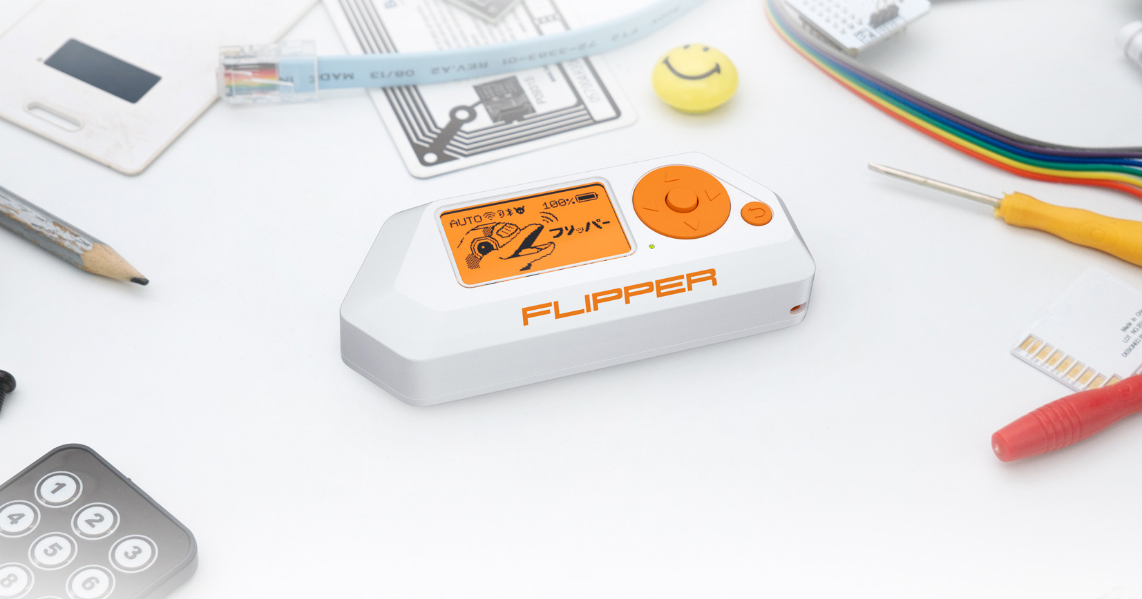
Based on ultra low power STM32 MCU for daily exploration of access control systems and radio protocols. Open source and customizable
looks useful but a bit pricey
 twin hedge
I'm making a board to use a ESP32-C3-WROOM-02-N4, but I've never soldered surface-mounted components. Where should I start?
twin hedge
woven bluff
looks useful but a bit pricey
I have one. I'm not exactly sure how to explain my thoughts on it, but I can say that it is fun to have, and it can actually be useful.
unreal flax
twin hedge
I'm making a board to use a ESP32-C3-WROOM-02-N4, but I've never soldered surfac...
You might consider getting it professionally assembled by the PCB house.
twin hedge
unreal flax
You might consider getting it professionally assembled by the PCB house.
I'll probably do that. I'd just mess up the build anyways.
twin hedge
I could use some help with parts. I'll attach the photos of my hand-drawn schematics. My LDO is a LD1117A. Should the resistors be 1/4W resistors? Also, what type of capacitors should I use?


 cursive sentinel
Those resistors are used for feedback, so they'll generally draw a couple mA at most. For caps I would recommend a mixture of electrolytic for the larger ones and ceramic for the smaller.
twin hedge
Alright. What kind of switches should I use for for the boot pin and the reset pin?
cursive sentinel
Push buttons with RC filters to debounce should be alright.
twin hedge
cursive sentinel
Push buttons with RC filters to debounce should be alright.
I've seen KMR2 switches used in other circuits for ESP32 modules. In the schematic for the ESP32-S2 and ESP32-S3 Feather boards, an RC filter is only used on the reset button. I'll use the same resistor and capacitor values in my schematic. However, I'm wondering if I can just use any KMR2 switch, or if I have to choose based on other factors. Also, would the capacitor in the RC filter be ceramic?
woven bluff
without Schmitt trigger, you'll need a big cap, bounce can be quite long
unique patio
I don't think the cap is for debouncing, but is to prevent stray resets from noise, etc. See 2.2.2 Reset in https://www.espressif.com/sites/default/files/documentation/esp32-s2_hardware_design_guidelines_en.pdf
twin hedge
unique patio
I don't think the cap is for debouncing, but is to prevent stray resets from noi...
That's what I was thinking. I've noticed that I can only find switches for 32V@0.5A, so do I just use one of those?
idle python
distant raven
It would be easier if you shared your files zipped up so everything can be evalu...
was gone for a few days
distant raven
idle python
can you include a pdf of your schematic?
tough matrix
what is a good MCU for most basic projects (blinking some LEDs)?
requirement:
cheap
Arduino compatible
easy to hand solder
I used to use attiny85.
is there something better nowadays? or is it still the best choice?
cursive sentinel
The "best" choice is whatever meets your requirements.
elder peak
I think there's a few of the new-series AVR in DIP format.
But, dono, I think everything's moved towards that which is hard to hand solder.
unique patio
twin hedge
That's what I was thinking. I've noticed that I can only find switches for 32V@0...
those are the maximum ratings, so they are perfectly fine.
tough matrix
elder peak
But, dono, I think everything's moved towards that which is hard to hand solder.
I am fine soldering SOIC packages, but not TQFP
elder peak
Is there a SAMD11 core that's maintained?
distant raven
Mattair compiles
elder peak
There's some STM32 parts that are TSSOP-20 or SOIC-8 that are covered by the STM32Duino core.
And there's the new-series of AVR's
tough matrix
sure, but they are unlikely to be cheap
elder peak
Yah, the TSSOP-20 STM32's are about the same.
elder peak
Which reminds me, I've got a STM32L041F6P7 that I should really actually screw with.
Like, I found this guy: http://www.technoblogy.com/ and he's been doing a lot with the new-series AVR for cute lil cheap projects
distant raven
I made my samd11 blink from Microchip studio lol
That’s about as far as I got with it. I got distracted trying to fix a logic analyzer Arduino sketch
elder peak
Well, it still means that your effort was flashier than mine.
twin hedge
unique patio
those are the maximum ratings, so they are perfectly fine.
I made a mistake. It's 0.05A, not 0.5A. Would it still work?
unique patio
Yes, the reset current is quite low
formal sand
tough matrix
what is a good MCU for most basic projects (blinking some LEDs)?
requirement:
ch...
I'd go with the STM32 families. The G0 and L0 are cheap and easy to get.
Also the tooling around the STM32 stuff is much better than what arduino can offer if you are thinking into moving into more serious work.
tough matrix
no, this is toy project to teach kids
for serious work I would indeed use stm32 or esp32
dry pelican
ATTiny probably meets those requirements pretty well
They don't make any new DIP uC designs (not 100% sure), so the older ones are definitely some of your only options
castellated modules are also hand-solderable if your kids are up for a challenge
so an ESP32-S2 module maybe
it is circuitpython compatible and native USB, so that's good
formal sand
Yeah I feel something like an ATtiny would be good
I have some DIP attiny25s those were neat
woven bluff
tough matrix
no, this is toy project to teach kids
lol, kids need to start with STM32, not obsolete tech
tough matrix
I feel it is a waste to use stm32 to blink 3 LEDs :)
formal sand
There are some that are meant for applications like that, usually the super cheap ones with very little ram and flash
woven bluff
tough matrix
I feel it is a waste to use stm32 to blink 3 LEDs :)
make them do native SDIO, and HID 🙂
supple pollen
tough matrix
I used to use attiny85.
is there something better nowadays? or is it still the b...
Some of the MSP430 chips come close. Normally they use in-circuit programming which is easy to wire but needs a programmer (not expensive, but it is another part). However there is the MSPBoot project that offers a bootloader. I don't know if there's direct Arduino hardware support, but Energia is available, which is an Arduino port for the MSP parts.
woven bluff
also old MCU require 5V rail
tough matrix
woven bluff
also old MCU require 5V rail
not attiny. those can work from 3.3
supple pollen
Here's a quick test I did a while back. Programming one using their "Spi-By-Wire" protocol takes 4 wires, two of which are power and ground. The inexpensive Launchpad boards include a programmer, including jumpers you can use like this to program offboard chips instead of physically moving chips into the socket to program them.

 flat vigil
formal sand
I'd go with the STM32 families. The G0 and L0 are cheap and easy to get.
flat vigil
formal sand
I'd go with the STM32 families. The G0 and L0 are cheap and easy to get.
I'm interested in the G0 too. It is programmable over I2C. JLC has some for 0.52 in singles
STM32G030F6P6 from STMicroelectronics - Microcontroller Units (MCUs/MPUs/SOCs) is available for JLCPCB assembly, check the stock, pricing and datasheet, and let JLCPCB helps you assemble the part STM32G030F6P6 for free.
formal sand
Wow that's really cheap
formal sand
Oh yeah the C0 is the new one they released, it is very interesting
flat vigil
ya, my guess is that it'll be cheaper in the long run but now it isn't very available
formal sand
Yeah they just released them not too long ago
Maybe it needs more time for them to build up stock
 inland jungle
are there any advantages/disadvantages to getting rid of the thermal breaks between copper pours and SMD pads? Since I'm using solder paste and a hotplate, it's easy enough to solder without the thermal breaks, so is there another reason to keep them in?
cursive sentinel
Well, better heat transfer for the thermal pads definitely. Otherwise I don't think there will be anything noticeable.
 bold basin
Will the "Adafruit LiIon or LiPoly Charger BFF Add-On for QT Py"(https://www.adafruit.com/product/5397) work with a regular Xaio(https://www.seeedstudio.com/XIAO-ESP32S3-Sense-p-5639.html) board? The QT py boards show A0-A3 which would imply Analog ports whereas the Xaio boards have them marked as D0-D3 which would imply Digital input. I'm guessing the charger board only really interacts with 5v and ground by default, but I wanted to make sure.
Is your QT Py all alone, lacking a friend to travel the wide world with? When you were a kid you may have learned about the "buddy" system, well this product is kinda like that! A ...

Seeed Studio XIAO ESP32S3 leverages dual-core ESP32S3 chip, supporting both Wi-Fi and BLE wireless connectivities, which allows battery charge. It integrates built-in camera sensor, digital microphone. It offers 8MB PSRAM, 8MB FLASH, and external SD card slot. All of these make it suitable for embedded ML, like intelligent voice and vision AI.
 pale umbra
are you allowed to sell electronics after you pcb them / 3d print them or everything sold require license 3d printer / extra charge when making the pcb / CE or FCC markings etc ?
dry pelican
tough matrix
no, this is toy project to teach kids
Ch554 or ch552 seems like a good one
dry pelican
bold basin
Will the "Adafruit LiIon or LiPoly Charger BFF Add-On for QT Py"(https://www.ada...
Should work
dry pelican
pale umbra
are you allowed to sell electronics after you pcb them / 3d print them or everyt...
Yes. Probably. Eagle's free license is non commercial, but FOSS programs like KiCAD allow you to sell what you make. JLC or any other manufacturers don't care if you sell or use for personal
And CE and FCC are only if you want to make a real product that needs to be compliant. Otherwise I think it just needs to be part 15 compliant which is automatically free. (I'm not sure. Not a lawyer)
dry pelican
bold basin
Will the "Adafruit LiIon or LiPoly Charger BFF Add-On for QT Py"(https://www.ada...
The xiao's d0-d3 pins are also adc pins
tough matrix
flat vigil
I'm interested in the G0 too. It is programmable over I2C. [JLC has some for 0.5...
thanks for the suggestion! do you have a link for programming them over i2c?
supple pollen
pale umbra
are you allowed to sell electronics after you pcb them / 3d print them or everyt...
You'll need to get FCC certification before you can put FCC markings on your product.
supple pollen
Who asked for what once?
pale umbra
adafruit once asked for and got a FCC certification for a shield
for some reason 4 of the fillings including the schematics are confidential despite adafruit normally publishing schematics/eagle files but this might have been before they became open
dry pelican
The filings are probably confidential. But adafruit always releases schems
They were always open
Sparkfun got fcc cert for artemis module
tough matrix
pale umbra
are you allowed to sell electronics after you pcb them / 3d print them or everyt...
you are certainly allowed to sell electronics - just look at tindie.com! or check the work of Unexpected Maker.
Sure, if your design is based on someone else's work (e. g. Adafruit), you need to check the license of the original work.
FCC certification is out of reach of almost all hobbyists, but you rarely need it - most of us, when we need wifi/Bluetooth/LoRa connectivity, use already certified boards or modules
depending on your local laws, if you generate enough revenue, you may need to register as a business - @distant raven can share his experience
cursive sentinel
Yeah you'd only need the certification if you were designing the RF board. Using an already-certified wireless module is fine assuming you don't modify it.
Although selling it in Europe might be more difficult
tough matrix
I sell some of my electronics, but my sale numbers are so low that I never bothered to make any official registration (do not tell this to IRS!)
cursive sentinel
As long as it's under like $10k/year I don't think the IRS cares.
distant raven
cursive sentinel
As long as it's under like $10k/year I don't think the IRS cares.
Though your state department of revenue might for unpaid sales tax
cursive sentinel
No sales tax in Oregon (although that's not necessarily a good thing).
supple pollen
idle python
The USB wiring looks dodgy to me. It looks like there's no USB connector, and the USB data pins on the LTE module and the USB/SPI module are connected together. Normally each would go to a USB connector.
worldly schooner
tough matrix
what is a good MCU for most basic projects (blinking some LEDs)?
requirement:
ch...
Ch55x are dirt cheap and soic, and I’m pretty sure someone has a working arduino core for it.
idle python
supple pollen
The USB wiring looks dodgy to me. It looks like there's no USB connector, and t...
the usb connector is just 2 pin holes
but on the pcb the traces from ft220x go directly to the lte module
and the usb connector gets usb traces close to where the usb points on the ft220x are

the blue pads where the traces go is the lte module
supple pollen
I'm not sure that's what you want to do.
idle python
supple pollen
I'm not sure that's what you want to do.
then what do i do
i still want access to the usb pins in case the spi pins dont work for whatever reason
worldly schooner
Even though it’s not super high speed signaling, it’s usually good practice to have length matching and impedance matching for usb, as it is a differential signal. Also, you probably want separate pins for each USB, as multiple usb drivers can damage each other if not interfere.
Ideally, you give them some space to have their own micro-b connector.
Or wire them to a usb hub/switch.
idle python
worldly schooner
Even though it’s not super high speed signaling, it’s usually good practice to h...
the length mismatch is not more than 3mm and the impedance is exactly 90 ohms
even if i gave the lte pads their own pins and the ft220x their own pins id still have to solder them both together
idle python
idle python
actually i can see why this would be wrong
if i wire the spi to a device and i also connect the usb pins to another device
the usb data incoming from both devices would be mixed
like if i send some data on device 1 then the lte will send the data requested by device 1 to both devices
idle python
idle python
like if i send some data on device 1 then the lte will send the data requested b...
if this is the only problem with the connection i made then i dont really care about it since obviously im not gonna connect both devices to spi and usb, pllus im the only one whos gonna be using this pcb
flat vigil
tough matrix
thanks for the suggestion! do you have a link for programming them over i2c?
I haven't found a great reference for the protocol. I know STM AN2606 lists what pins it is active on for all of the different boards.
ah, found it. AN4221
tough matrix
Nice.
I'd expect that someone has written an arduino script for flashing the bootloader to STM32 over i2c
elder peak
Heya, if I've got a switching power supply that's happy with Vin at 12V but the enable pin is only safe for 6V, if I just want a SPST switch to turn it on and off, the right answer is to make a voltage divider instead of just a pull-up resistor, right?
unreal flax
elder peak
Heya, if I've got a switching power supply that's happy with Vin at 12V but the ...
Yes, that seems right. It's a little bit unusual for an enable to not be happy with the input voltage, but if that's the case, a divider is the way to go. You can have the pulldown portion of the divider connected to EN, and the pullup portion of the divider on the other side of the switch.
elder peak
Yeah, I had three different step-down switching power supplies in my electronics hoard and 2/3 of them are happy with the enable line at the input voltage and this one... wasn't.
I haven't let the magic smoke out in years.
paper vale


Hello. I need some clarification please. I read an article about space vector modulation in the 60° coordinate system. I understood some parts but I have some incomprehension about the calculation of duty cycles. As for VLLg and VLLh, I don't quite understand what they refer to. According to the image VLL correspond to is when Vrg and Vrh are 0, 0 for example.
Does it mean that VLL correponds to the switching time 000 and Vuu to the switching time 111?
And what do VLLg, VLLh, VUUg and VUUh correspond to ?
 graceful sparrow
idle python
graceful sparrow
idle python
Seeing as I have done a very similar thing (I think), with an "Ai thinker ESP32-CAM" board, I would like to throw that out there as an idea, I used a nRF9160 feather (in AT command mode). I will post a link to the blog page that I wrote about it, and hope that is ok, a lot of info is there.
Feel free to use any of the information there if you would like to help your project.
All source code, etc is published there.
https://www.drassal.net/wp/nrf9160-esp32-cam-jpeg-image-uploader-through-lte/
Adafruit also sells a version of the nRF9160 board that is almost the same, just to throw out an Adafruit link too https://www.adafruit.com/product/4753. A wonderful little board, if you want to experiment with LTE connectivity.
vast flume
Hey guys, I am in need of help again 😦
I cannot, for the life of me, connect to a bmp581 over i2c. I am using a pcb that is a modified version of a pcb where the sensor worked perfectly so I am so confused as to what could cause this
This is the footprint for the sensor that I made

And this is the pinout from the datasheet

I have the sensor oriented so that the port hole is on the top right, which should be positioning it in the correct orientation
supple pollen
It looks like your footprint has the marker at the other corner, which is confusing. There's an interior layer trace that goes under pad 8 and just stops without connecting. Is the I2C bus working otherwise?
vast flume
Yeah I messed up with the marker on the silkscreen, since the only visible marking would be the port hole which should be in the top right corner
One min I took a picture


Also here is the datasheet I've been following https://www.bosch-sensortec.com/media/boschsensortec/downloads/datasheets/bst-bmp581-ds004.pdf
To make things even more confusing however, is this is also in the datasheet:

 idle python
graceful sparrow
Seeing as I have done a very similar thing (I think), with an "Ai thinker ESP32-...
idle python
graceful sparrow
Seeing as I have done a very similar thing (I think), with an "Ai thinker ESP32-...
were you able to do more complex things like send video files or make websockets with the nRF9160 ? im trying to make the esp32 cam livestream the camera feed with the lte module but the uart interface is not beefy enough for such task
pale umbra
tough matrix
depending on your local laws, if you generate enough revenue, you may need to re...
Thanks. The part about registring business/tax etc is very familiar to me since I worked in that before for peoples that wanted to do this so Im very familiar with my state laws on this
rigid plume
What do you folks think of this ESP32 S3 soc based dev board (breadboard comp.)

500ma battery charging ic, batt fuel guage, rgb led, rf switch for ipex or pcb antenna and extra psram footprint on the bottom side of the board and cp2102n UART
unreal flax
rigid plume
I'd be a little bit worried about the proximity of the header pads right at the side of the PCB antenna.
rigid plume
unreal flax
I'd be a little bit worried about the proximity of the header pads right at the ...
Yeap me too, but I ordered some of the pcbs for a reference and they seem to be at an safe distance away
I don't think too much interference will be caused anyways with that.
 frosty scaffold
Can I get some feedback on my schematic? It's supposed to be an ESP32 CANBUS reader/datalogger that uses 5V. I plan to use SPIFFs for datalogging.
 rigid plume
frosty scaffold
Can I get some feedback on my schematic? It's supposed to be an ESP32 CANBUS rea...
rigid plume
frosty scaffold
Can I get some feedback on my schematic? It's supposed to be an ESP32 CANBUS rea...
Can you show your whole circuit incl usb?
Also connect the EP pins to GND
frosty scaffold
rigid plume
Can you show your whole circuit incl usb?
No USB. I would be writing the firmware to the ESP32 directly using one of these and use ElegantOTA to push firmware updates. https://www.amazon.com/gp/product/B08K2JKNRK/ref=ppx_yo_dt_b_search_asin_title?ie=UTF8&psc=1

ESP32 Development Board Module High Precision Test Burn Fixture for ESP-WROOM-32 Minimum System
frosty scaffold
rigid plume
Oh sure, that's great
Tell me more?
rigid plume
 frosty scaffold
Ah one moment
Better? Do the capacitors look good? Should I add a capacitor to the input as well?

 pale umbra
what are the caps for here ?
frosty scaffold
 frosty scaffold
pale umbra
what are the caps for here ?
frosty scaffold
pale umbra
what are the caps for here ?
Filtering high voltage spikes
rigid plume
frosty scaffold
Great
frosty scaffold
rigid plume
Great
One more thing: Should terminal 4 and terminal 2 of the AMS1117 be connected instead of terminal 4 going to GND? I saw some conflicting documentation in some schematics online
rigid plume
frosty scaffold
One more thing: Should terminal 4 and terminal 2 of the AMS1117 be connected ins...
Term 4 is for heat dissipation, if you connect it to the gnd plane. Term 2 is the voltage out, if you connect them both it would short
 frosty scaffold
rigid plume
Term 4 is for heat dissipation, if you connect it to the gnd plane. Term 2 is th...
frosty scaffold
rigid plume
Term 4 is for heat dissipation, if you connect it to the gnd plane. Term 2 is th...
Gotcha, thanks for the clarification
rigid plume
Also this is an TAC for the SN65HVD230D, you can put a 0.1uf decoup cap on vcc
You can add the act45b-101-2p-tl003 to supress noise
Will it only be for datalogging?
frosty scaffold
Yep, and sending some CAN signals if necessary
rigid plume
Oh, well then you can follow this. This is probably the best one

The diodes can be added which are the DFN1006-2L-BI-1 ( https://www.lcsc.com/product-detail/ESD-Protection-Devices_WILLSEMI-Will-Semicon-ESD5611N-2-TR_C2939834.html)
ESD5611N-2/TR WILLSEMI(Will Semicon) US$0.0697 - DFN1006-2L ESD Protection Devices ROHS datasheet, price, inventory C2939834
After doing this your fine
frosty scaffold
Hmm what are R18 and R21? 10 ohms respectively?
10R is a bit vague
Also, what direction are the diodes facing?
rigid plume
frosty scaffold
Also, what direction are the diodes facing?
Nope they are not polarised
rigid plume
frosty scaffold
10R is a bit vague
I think they are using them to prevent some filtering or interference.
The 120R termination resistor is already there so I don't see any problems with adding them
Also one last thing with your esp32 power input you should add an 0.1uf cap series to the 10k resistor to gnd from en.
 frosty scaffold
Ah thank you
rigid plume
That covers everything, I hope I could help
frosty scaffold
rigid plume
That covers everything, I hope I could help
 frosty scaffold
rigid plume
That covers everything, I hope I could help
frosty scaffold
rigid plume
That covers everything, I hope I could help
You were a great help! PCB designing time.
rigid plume
frosty scaffold
Great
Just put NC on the pins you won't be using

Also you forgot a GND on the esp32 module
frosty scaffold
Ah i see it
rigid plume
On pcb design, make sure the decoupling caps are close to the ic inputs, they should not be far away
For the 5v input use 0.8mm on the traces, then on the input to the esp32 0.5mm is fine
0.254mm for everything else
frosty scaffold
 rigid plume
frosty scaffold
rigid plume
frosty scaffold
Looks great!
frosty scaffold
Dope! Can I come back for more feedback when I have the PCB designed?
rigid plume
Yeap, I work with easyeda alot so that should be fine with me.
Also did you want power efficiency?
The AMS1117 is always overkill for most simple circuits
I recommend https://www.lcsc.com/product-detail/Linear-Voltage-Regulators-LDO_Torex-Semicon-XC6220B331MR-G_C86534.html
XC6220B331MR-G Torex Semicon US$0.3675 - 50dB@(1kHz) 1A Fixed 3.3V~3.3V Positive 6V SOT-25-5 Linear Voltage Regulators (LDO) ROHS datasheet, price, inventory C86534
It's small and can still produce 1A, and works great with battery power circuits aswell
pale umbra
rigid plume
so about this pic, I checked that linear regular and it seems to convert 100 uA @ 5V to 1A @ 3.3V which kinda surprise me. I thought this was something to use usb as a power supply ?
but the datasheet says the max input current is 100 uA and supply voltage is 1.1V to 6.8V
rigid plume
the 100 µA figure you've mentioned refers to the quiescent current of the device.
It is the amount of current consumed by the device when it is not actively regulating eg when no load is connected or the output is not enabled.
The 1A is the max the load can draw from the LDO @ 3v3
pale umbra
rigid plume
The 1A is the max the load can draw from the LDO @ 3v3
Thanks for taking the time to answer. I like to learn from actual choices of peoples more knowledgeable than me and understand why those choices were made!
frosty scaffold
rigid plume
I recommend https://www.lcsc.com/product-detail/Linear-Voltage-Regulators-LDO_To...
I actually could use a recommendation. I am currently stepping the power down from 55V to 5V and then again from 5V to 3.3V. Do you have a recommendation for something that could step down from 55V to 3.3V? I found a few regulators that could work, but I'm a bit skeptical since ESP32 could draw a lot of current when in Wifi, specifically for OTA updates.
rigid plume
frosty scaffold
I actually could use a recommendation. I am currently stepping the power down fr...
The max the esp32 module your using should be around 600ma, your fine
That's steep from 55v
Checkout this https://www.lcsc.com/product-detail/DC-DC-Converters_Texas-Instruments-LMR36520FADDAR_C1858395.html
LMR36520FADDAR Texas Instruments US$1.8248 - Step-down type Adjustable 4.2V~65V 2A 1V~28V SO-8 DC-DC Converters ROHS datasheet, price, inventory C1858395
You won't get a decent efficiency, but it can output 2A aswell as support 5v upto 65v
frosty scaffold
Yeah, it's a battery pack for a ~48 volt Lipo battery. The BMS on that battery has a LM5017 buck regulator and was thinking of using one of those, but the rated max current is 600ma, which is really dang close
rigid plume
 frosty scaffold
2A is hecka decent
rigid plume
This is the circuit for 3v3 output using that https://www.lcsc.com/product-detail/DC-DC-Converters_Texas-Instruments-LMR36520FADDAR_C1858395.html
LMR36520FADDAR Texas Instruments US$1.8248 - Step-down type Adjustable 4.2V~65V 2A 1V~28V SO-8 DC-DC Converters ROHS datasheet, price, inventory C1858395
pale umbra
Honestly it's just the esp8256 that has current issues with wifi That was sorta solved in esp32s. From what I can see the wifi uses about 200mA in "active mode" (ie: when not just maintaining connection to the AP)
frosty scaffold
Efficiency isn't that important considering that the battery is huge
Oh I should mention that the ESP32 is in AP mode
pale umbra
where as on the esp8256 sometimes the wifi will draw almost to the max current of the MCU
rigid plume
frosty scaffold
Efficiency isn't that important considering that the battery is huge
Yeap, just the IC is a bit expensive
frosty scaffold
$2 is alright
pale umbra
A shame that the esp32 doesnt have a low-power sleep mode for wifi it would be almost perfect with that 😄
rigid plume
I reccommend you this tool for checking what ICs you need https://webench.ti.com/power-designer/switching-regulator
frosty scaffold
Ah thank you!
rigid plume
pale umbra
A shame that the esp32 doesnt have a low-power sleep mode for wifi it would be a...
I think it does
It is on the newer versions (s3)
pale umbra
rigid plume
It is on the newer versions (s3)
hmmm I checked the S3 manual to say this statement and it says: "In Deep-sleep and Light-sleep modes, the wireless peripherals are powered down. Before entering Deep-sleep or Light-sleep modes, the application must disable Wi-Fi and Bluetooth using the appropriate calls (i.e., esp_bluedroid_disable(), esp_bt_controller_disable(), esp_wifi_stop()). Wi-Fi and Bluetooth connections will not be maintained in Deep-sleep or Light-sleep mode, even if these functions are not called."
That is why I was saying it doesn't have a wifi sleep / low-power mode as it doesn't seems like it will even maintain the AP connection
rigid plume
pale umbra
That is why I was saying it doesn't have a wifi sleep / low-power mode as it doe...
Well I don't think low power mode with wifi on is necessary for some applications
Deep sleep is enough for most, where the s3 will power on and send a signal or something with wifi then go back to sleep
pale umbra
I had hoped for a wifi wake-ip when I got my S2/S3s but it doesn't seems possible since you have to call methods to turn it off
For a small IoT device that did data gathering of a single sensor and I was hoping that adafruit-io/rpi base station could ping it every 10 mins by wifi. Had to change my approach because of this and it's annoying because it requires precise timing and checking time on both ends
frosty scaffold
@rigid plume Ready for feedback 🙂
 rigid plume
frosty scaffold
<@545518928869326863> Ready for feedback 🙂
rigid plume
frosty scaffold
<@545518928869326863> Ready for feedback 🙂
Also will you use JLCPCB to manufacture the pcb?
Will you assemble it yourself?
frosty scaffold
rigid plume
Will you assemble it yourself?
Probably yes. I’m thinking of getting the boards made by JLCPCB and maybe partial SMD assembly so that way I can flash the ESP32 modules myself and solder them on by hand?
Open to ideas of course
If it’s not evident, this is definitely my first time doing this lmao
supple pollen
I like the placement of C9, but I'm less fond of the long trace coming from it and going the long way around the board where it's going to impact the antenna's field
rigid plume
frosty scaffold
Probably yes. I’m thinking of getting the boards made by JLCPCB and maybe partia...
That's definitely fine, I'll remove the esp32 s3 from the BOM. You will just have to buy it from lcsc separately
assembly from jlcpcb will save you alot of time with small components
Is it fine if I put the antenna off the board?
You will get better signal
@frosty scaffold
supple pollen
Yes, I've seen many designs where the antenna hangs off the edge of the board. This works well and saves board space, but it does add an opportunity for the antenna to get impacted
rigid plume
Yeap definitely
frosty scaffold
rigid plume
Is it fine if I put the antenna off the board?
Yep no problem. This entire board is likely going to be potted for water resistance anyway
rigid plume


I added a GND plane for simplicity, I then also made sure the traces were not right angled (not good for signal integrity)
For a simple board like this I think this is definitely enough
frosty scaffold
Ah, thank you!
rigid plume
If you solder on the esp32 , I recommend an hot airgun aswell as an soldering iron to correct some joints
supple pollen
And flux. Flux is your friend.
frosty scaffold
rigid plume
If you solder on the esp32 , I recommend an hot airgun aswell as an soldering ir...
Dumb question, how do I view the front of the board?
frosty scaffold
supple pollen
And flux. Flux is your friend.
I bought a lifetime supply of no clean liquid flux lmao
rigid plume
frosty scaffold
Dumb question, how do I view the front of the board?

Also if you want to learn more about easyeda and routing and design in general of esp32 boards watch Robert Ferranec. https://www.youtube.com/watch?v=S_p0YV-JlfU

In this tutorial you will learn how to draw schematic, do PCB layout, manufacture your board and programming.
Learn more about electronics, check out our online courses:
https://courses.fedevel.com/
Chapters:
00:00 Start a new project in EasyEDA
04:00 Add ESP32 into schematic
05:00 Add CP2102N
05:48 Add AMS1117-3.3
06:41 Add USB connector
07:4...
frosty scaffold
rigid plume
Also if you want to learn more about easyeda and routing and design in general o...
I was also following that video!
frosty scaffold
rigid plume
Found it!
frosty scaffold
@rigid plume Another dumb question: My 22 uF capacitors are out of stock. How do I replace them in the boardview and go back to schematic mode?
graceful sparrow
idle python
were you able to do more complex things like send video files or make websockets...
I don't think LTE-M or NB-IoT (the IoT lightweight version of LTE protocol which this nRF9160 does) has the bandwidth to do live streaming. It takes several seconds to upload an image. If you would like to live stream the camera I think you will have to go with a full blown LTE connection. But for doing things like IoT devices (MQTT connections, Azure, etc) the nRF9160 works great.
Personally I would try this project with a Rapsberry Pi Zero and a LTE modem (laptop version (mini PCIexpress with USB adapter). Most of the laptop cards work off a USB interface, then it is a matter to get a working driver setup on the Rapsberry Pi, then just treat it almost like a WiFi connection. Just make sure the adapter has a SIM socket, some do not.
For instance, these two below products might work well with a Raspberry Pi.
https://www.amazon.com/dp/B07YY5967K
https://www.amazon.com/dp/B079QG22NS

Mini PCI-E to USB Adapter With SIM card Slot for WWAN/LTE Module Description The adapter is designed for desktop/Embedded system that converts 3G/4G wireless Mini-Card to USB port. You can only insert your USB Bus type minicard such as GSM, HSPA(3.5G), GPS, LTE cards to this adapter then plug to ...

EM7455 4G Module Network Card, PCIe M.2 Replacement Wireless EM7455 Network Card for DW5811e 3P10Y 300 Mbps 4G LTE WWAN NGFF Card Module Fit for PC Laptops
The EM7455 might need the firmware rewritten to enumerate correctly, internet searches should reveal that process.
graceful sparrow
frosty scaffold
<@545518928869326863> Another dumb question: My 22 uF capacitors are out of stoc...
If the footprint (package) is the same, there is no need to change that, just change your BOM file that you will send to the board house. But, yes, edit the component information in the schematic view, if you need to change the footprint, change it in the schematic view, then reimport the changes into the boardview (KiCad is it?). It will update only change components.
If the board layout is complete, I would recommend to find a replacement component that fits the original componenet's footprint, since this is the option that requires the least amount of work (and changes).
graceful sparrow
frosty scaffold
Probably yes. I’m thinking of getting the boards made by JLCPCB and maybe partia...
For pre-flashing, this is a cool solution.
https://www.amazon.com/dp/B08K2JKNRK
I have one for each type of ESP32 module.
ESP32 Development Board Module High Precision Test Burn Fixture for ESP-WROOM-32 Minimum System
Make sure to get the one that matches your part.
frosty scaffold
graceful sparrow
If the footprint (package) is the same, there is no need to change that, just ch...
I’m using EasyEDA
graceful sparrow
frosty scaffold
I’m using EasyEDA
Ah I'm sorry I have really only experience with KiCad, but, the same should still apply. As long as you choose a part that is the same size you will not have to modify the board layout (recommended). If you search for the specific part on Digikey there will be a specification that shows size (0402, 0603, etc). Match this package size up with the replacement part. Sometimes Digikey will even offer replacement suggestions at the bottom of the page that might be compatible.
In this case, you will only need to modify the part's BOM (parts list) data, which is most likely in the schematic view (if you edit the part).
frosty scaffold
graceful sparrow
Ah I'm sorry I have really only experience with KiCad, but, the same should stil...
I’m trying to get it fabricated by JLCPCB using EasyEDA’s built in utility, how would I swap it?
graceful sparrow
frosty scaffold
I’m trying to get it fabricated by JLCPCB using EasyEDA’s built in utility, how ...
Looks like this might be the way to do it, with just a quick internet search.
https://easyeda.com/forum/topic/Replace_part_in_schematic-aEasKEVdv
frosty scaffold
graceful sparrow
Looks like this might be the way to do it, with just a quick internet search.
ht...
Dang, it looks like I gotta modify the original schematic, and I don't have the original schematic. Guess I gotta do it the long way
graceful sparrow
frosty scaffold
Dang, it looks like I gotta modify the original schematic, and I don't have the ...
Ah, the BOM parts data must be stored somewhere (see if you can get access to that and edit it). But honestly the PCB layout should not change and just requires a part substitution (part should be the same size). I'm sorry that is the extent I can assist with this as I am not too familiar with EasyEDA but hope you get it sorted out.
graceful sparrow
frosty scaffold
Dang, it looks like I gotta modify the original schematic, and I don't have the ...
Here is one more link, try this editing method. https://easyeda.com/forum/topic/BOM_edit-APlfxrJDV
You may be able to open the file with a text editor (KiCad files can be edited this way). And do a find/replace on the part information.
If the data is not stored binary.
frosty scaffold
@rigid plume I made another revision! Would you be able to give feedback?
frosty scaffold
woven bluff
can flyback or boost regulator drive non-flyback transformer?
rigid plume
frosty scaffold
<@545518928869326863> I made another revision! Would you be able to give feedbac...
Yeap will check it soon
rigid plume
@frosty scaffold It looks fine and everything will probably work. Just consider these points when designing a pcb.
- Route at 45* Angles, not at 90* (You will lose signal integrity)
- Use the grid lines as a way to neatly route your connections
Avoid sharp traces like this
 supple pollen
woven bluff
can flyback or boost regulator drive non-flyback transformer?
supple pollen
woven bluff
can flyback or boost regulator drive non-flyback transformer?
Not very efficiently. Flyback transformers have a gap in the magnetic path which stabilizes the inductance and stores energy. Without that gap, the core will saturate more easily (which is hard on the switching transistor) and without the additional energy storage of the gap, each pulse out of the transformer will contain less energy, reducing both the efficiency and power capability of the regulator.
For that trace coming in from the left at the bottom, going to the same pad as the trace from the upper left, I'd have the traces join to the left of the pad. This will also avoid cutting through the ground plane for the bottom pin.
idle python
graceful sparrow
I don't think LTE-M or NB-IoT (the IoT lightweight version of LTE protocol which...
lte-m has a speed of 1mbps on both up and down, b ut the ec800 is an lte cat 1 module with 5mbps upload and 10mbps download
with the esp32 cam having only MJPEG format, i could send over a 480p video on 30fps with low quality mjpeg, its not much but its something
i think i should just remove the ft220x chip, and add a raspberry pi zero in the project so it could convert the video feed from mjpeg to h264 and i connect the ec800 to the pi instead, no need for spi pins at all and no need for custom driver
supple pollen
Note, those are ideal speeds, and you'll often get less (sometimes much less) under real world conditions
graceful sparrow
idle python
lte-m has a speed of 1mbps on both up and down, b ut the ec800 is an lte cat 1 m...
Yes, for occasional sending of images I think NB-IoT or LTE-M would be ok but wouldn't recommend it for streaming. Also consider the interface between your MCU and the nRF9160. If you use UART you might be able to do 921600 but I could not get that speed to work reliable. At those speeds the length of wires and noise will start to become important. 115200 is ideally what I have been able to get to work reliably (with an ESP32).
I would look down the Rapsberry Pi Zero path, as it also has a built in camera interface, and access to a fast USB interface to an LTE modem.
idle python
graceful sparrow
Yes, for occasional sending of images I think NB-IoT or LTE-M would be ok but wo...
yea i think im gonna use a rpi for the networking
but ill still use the esp32 as the camera cause i cant buy a csi camera right now
supple pollen
I agree, trying to squirt video over an asynchronous serial link seems iffy
graceful sparrow
idle python
but ill still use the esp32 as the camera cause i cant buy a csi camera right no...
You might find a bottleneck with the connection between the ESP32 and the Raspberry Pi (UART).
I believe the camera interface operates around 2M, I would have to verify that, but you might have trouble getting your data transfered fast enough. You will also have to devise a protocol to pass the data.
cursive sentinel
supple pollen
I agree, trying to squirt video over an asynchronous serial link seems iffy
DisplayPort does this
supple pollen
I'm pretty sure DisplayPort is synchronous
graceful sparrow
Best choice is to just take advantage of the Raspberry Pi camera interface (when you can acquire a Raspberry Pi camera).
The work has already be done and all you have to worry about is the software (personally I might use Python).
cursive sentinel
The minimum data rate is also 1.62Gbps though.
supple pollen
A little reading shows that DisplayPort is neither, it's isochronous...
cursive sentinel
But yeah you're not going to be able to send video data through a UART.
idle python
graceful sparrow
You might find a bottleneck with the connection between the ESP32 and the Raspbe...
i wont need uart cause the esp32 makes its own wifi network and i can just make the pi grab the video from the web server esp32 is hosting
graceful sparrow
idle python
i wont need uart cause the esp32 makes its own wifi network and i can just make...
Ok yes, I forgot, that is an option, but adds a little complexity to the system.
cursive sentinel
Architecturally it is an asychronous interface though. Self-clocking.
Note: I do device characterization for video SERDES parts.
supple pollen
Right, self-clocking differential signal, not the scheme with start bits and stop bits like the sort of single ended asynchronous serial you get out of a UART.
cursive sentinel
Correct
graceful sparrow
idle python
i wont need uart cause the esp32 makes its own wifi network and i can just make...
If you do this, watch the work load on the ESP32, I have read the camera (or ESP32) can overheat if heat is not managed properly.
They do get hot when you stream, I made a WiFi streamer (streamed to a websocket on a server running Python) with the Ai Thinker ESP32-CAM (as a proof of concept) and it did get rather warm.
supple pollen
To me, "self clocking" is distinguished from (UART style) "asynchronous", even though neither of them have a separate clock signal like synchronous serial. The main difference being the number of bits you have to wait to resynchronize.
The timing benefits of a differential (versus single ended) signal are important too.
idle python
great
now i just have to remove the spi bridge chip
from the pcb i made and get a rpi zero 2
graceful sparrow
idle python
i wont need uart cause the esp32 makes its own wifi network and i can just make...
With that thought, if you want to try the streaming route, and want to direct the ESP32 to a Raspberry Pi running a Python script I might be able to give you a head start (the ESP32 code and some Python script to work with). The ESP32 sends a stream of data to a websocket (opened by a Python script on a server) which then accepts connections from browsers to watch the stream. My stream was simple though, it was a stream of JPEG images, not an actual stream, but it might be a starting point.
supple pollen
Amusingly, it's probably easier these days to get a Pi compatible camera than a Pi Zero 2.
graceful sparrow
They should be fairly common off Amazon (made in China) which I don't mind at times when it is just for a proof of concept.
idle python
supple pollen
Amusingly, it's probably easier these days to get a Pi compatible camera than a ...
i can get one from aliexpress for just 10 dollars but i dont know about the quality
supple pollen
I avoid sketchy sources like amazon for proof of concept, as spending extra days debugging isn't appealing at all. Aliexpress is a better bet.
graceful sparrow
But I hear the Raspberry Pi should be returning down to realistic prices by the end of this year, or early next as supply chains are reestablished.
supple pollen
When qq_ said "right now", I figured "by the end of this year" may not be in scope
graceful sparrow
Does Adafruit have any inexpensive Raspberry Pi cameras? I should take a look, they might.
$35 is not bad https://www.adafruit.com/product/5658
$25 too https://www.adafruit.com/product/5659

Raspberry Pi Camera Module 3 is a compact camera from Raspberry Pi. It offers an IMX708 12-megapixel sensor with HDR, and features phase detection autofocus. Camera Module 3 is available in ...

Raspberry Pi Camera Module 3 is a compact camera from Raspberry Pi. It offers an IMX708 12-megapixel sensor with HDR and features phase detection autofocus. Camera Module 3 is available ...
I had to edit that post, an auto bot kept rejecting my post with a link...
cursive sentinel
supple pollen
To me, "self clocking" is distinguished from (UART style) "asynchronous", even t...
You are correct in saying it is isochronous. That's the term used in the DP spec. The fact it is differential has more to do with signal integrity than timing though, aside from the fact that the differential signals are AC coupled. The actual self-clocking mechanism is handled by the data scrambler and line encoding (8b10b for DP1.x, 128/132b split over four lanes for 2.0).
graceful sparrow
idle python
great
Adafruit is out of stock on all Raspberry Pi variants now it seems, but I remember hearing stock is occasionally put up so just click that "notify me" button and try to snag one as soon as stock appears. I would love to get my hands on a Zero 2 when I can.
supple pollen
The problem with a single-ended signal is the need to differentiate high and low levels using a threshold. A little noise might make the transition earlier or later. A differential signal usually uses a crossover threshold with hysteresis, which minimizes that jitter.
idle python
graceful sparrow
Adafruit is out of stock on all Raspberry Pi variants now it seems, but I rememb...
maybe i can get a banana pi m2 instead or another radxa zero? i have this radxa zero but its broken cause i tried to desolder the headers
graceful sparrow
idle python
maybe i can get a banana pi m2 instead or another radxa zero? i have this radxa ...
Yes that works too, not sure on the camera interface compatibility, but if using the ESP32 for the camera then that can be a starting point, assuming you have the SD card prepared for it.
cursive sentinel
supple pollen
The problem with a single-ended signal is the need to differentiate high and low...
Yes, but that's still independent of the timing. There are multiple reasons you might want to use a differential signal, but the interface timing is not one of them.
idle python
graceful sparrow
Yes that works too, not sure on the camera interface compatibility, but if using...
which one would be the fastest at re encoding mjpeg to h264 tho
banana pi or radxa zero
graceful sparrow
idle python
which one would be the fastest at re encoding mjpeg to h264 tho
Sorry not my area of expertise, but you could do some tests (using Python or such) if you have both of them functional.
graceful sparrow
idle python
which one would be the fastest at re encoding mjpeg to h264 tho
That encoding might be CPU intensive unless you have hardware support (I think Raspberry Pi has hardware support?).
cursive sentinel
It does.
And hardware encoding is the only way you're going to be able to get a processor like that to encode H.264 fast enough.
graceful sparrow
idle python
which one would be the fastest at re encoding mjpeg to h264 tho
↑↑↑
idle python
pi zero 2 isnt in stock anywhere unless you wanna buy it for 90 dollars
should i just buy a pi zero or a radxa zero
wrong channel
woven bluff
all pi SOCs have been out of stock for years
pale umbra
When I finally got my pi 4 b 8gb I opened a bottle of champagne. Also I waited for when I actually had it in my hands because the shipping trucks could have been raided like those bak trucks carrying gold ingots 🤣
idle python
woven bluff
all pi SOCs have been out of stock for years
well my only choice is buying a board that has little software support or buying a board thats weaker but great software support
i dont know if a raspberry pi zero with hardware encoding support on ffmpeg would be better than boards like radxa zero, mango pi, banana pi which have better hardware but no hardware encoding support (not that i know of, maybe there is hardware encoding support)
im not gonna be re encoding 1080p 60fps videos, esp32cam or a csi camera couldnt even dream of reaching those resolutions and fps at the same time
most im gonna be doing is 720p at max 30fps which shouldnt really be heavy on any of the boards i just mentioned


 twilit mango
Hey folks. I have a weird question. I already talked to one of my folks who is relatively familiar with EagleCAD, and he didn't know. I also googled for an answer, and I'm finding only solutions for AutoCAD 2015-2018, and the one post I found for EagleCAD was unanswered. I have a kludgey workaround. However, before I accept it and give up, I figured I would ask here on the off chance one of you lovely people happens to know the answer.
I would like to move the dimension value text to the left side of the measurement from the right, to where it very adamantly defaults.

That way it can be next to the measurement to its right without the text overlapping.
pale umbra
can you show a bit more of the right side ?
pale umbra
It might just be conforming to engineering rules about aligning measures
But Id need to see if it has a continuous line going to center of says an hole to conform to engineering standards for plans
twilit mango
 pale umbra
so you want the 0.10 on the other side because it's showing the size of the bottom-left hole ?
twilit mango
I want it on the other side so I can make it closer to the board, and not have it overlap like this.

Smaller measurements are to the right. Larger ones are between the lines. If that wasn't already obvious.
I'm thinking the reason all I was getting were AutoCAD results is because it is perhaps not possible in EagleCAD.
pale umbra
Im still not sure what it is measuring 🤣 so confusing having it on the right side
pale umbra
Like I dont know if its measuring the big hole on bottom-left or the distance between the green IN hole and the S- one
twilit mango
Not sure myself if it's a mounting hole or not, but we like to have thorough dimensions.
Oh!
twilit mango
pale umbra
Like I dont know if its measuring the big hole on bottom-left or the distance be...
It's way more obvious when they are not overlapping
I did that to show my frustration.
That's not how it's going to be in final.
Here is my kludgey workaround. I changed the size of the text. Is that clearer to you?
 unreal flax
Does applying the rotate or mirror operation to the measurement object do anything?
twilit mango
unreal flax
Does applying the rotate or mirror operation to the measurement object do anythi...
Oooooh. Not sure, trying that.
Mirror won't apply to it. Refuses to even accept it as a mirrorable object.
Same for rotate.
idle python
twilit mango
Here is my kludgey workaround. I changed the size of the text. Is that clearer t...
new product?
twilit mango
idle python
new product?
NeoKey Key Switch Socket Breakout for CHOC key switches.
It's in the shop. 🙂
I'm writing the guide.
pale umbra
all you seem able to do is to measure it upside down so it show on the other side vs left-right
twilit mango
Actually, perhaps better workaround, I'll move the 0.33 measurement to the top of the board. Both sets of pads are available there too. It will fit there inside the full board width measurement.
pale umbra
like with the 0.10 atop the lines instead of at the bottom like in your pic
twilit mango
Yeah.
That's better.

Usually it's routing the board that turns into a puzzle, not adding the dang measurements. Uff!
twilit mango
Measures
pale umbra
dont know if that is planned but are diameter/measure of the mounting holes usually included?
twilit mango
Thanks for looking into this with me, folks! I appreciate it. I feel sort of better that no one else can figure it out either, and at this point feel like it's simply not possible.
twilit mango
pale umbra
dont know if that is planned but are diameter/measure of the mounting holes usua...
They're included in the fabrication print image that is on the Downloads page in the guide.
The PCB files are always there to check yourself, but we include images of the board and schematic so folks don't necessarily need Eagle to look at them.
pale umbra
I tried many tools on the measures layer and nothing seems to let me adjust where the dimension is/alignment/style etc
twilit mango
Thank you
idle python
did adafruit ever produce white pcb versions of the powerboost 1000c
pale umbra
I miss autocad dimension styles now 😦