#help-with-hw-design
1 messages · Page 12 of 1
 summer pier
 long wraith
Lots and lots of single cell BMS boards available on eBay
Might take a month or two to get from China… but they’re there and cheap
 distant raven
Orrrr hear me out.. https://www.adafruit.com/product/1904

Oh so handy, this little lipo charger is so small and easy to use you can keep it on your desk or mount it easily into any project! Simply plug it via any MicroUSB cable into a USB port and ...
long wraith
That’s just a charger tho — won’t help with overcurrent/undervoltage on discharge
LiPoly BFF is the full management package, but it’s also good practice to have a BMS on the cell
distant raven
Mcp73831 has built in charge protection
long wraith
Is that what’s on the MicroLipo? That’s only a charger tho
long wraith
But the cell won’t have overdischarge protection still
distant raven
Most lipos cut off at 3V
distant raven
Are from supplies you probably shouldn’t trust anyway and should avoid
long wraith
Or they’re raw cells meant to be used with a BMS
distant raven
Modern and reputable LiPo suppliers can very cheaply add them.
And they regularly do
You don’t really need raw LiPo packs unless you’re building your own multicell setups
long wraith
I use recovered LiPo cells from laptop batteries, which don’t have individual protection, just a shared BMS… maybe they’re doing the same?
Actually… @summer pier were you just looking for a small charger? Or do you want to have battery management as part of a larger project?
distant raven
It’s either a single cell or a parallel cell battery based on the voltage given
long wraith
Yeah. But there’s the question of if they’re trying to add battery management into a board, or design their own version of the MicroLipo, or protect a raw cell that lacks overdischarge or what
distant raven
Harvesting LiPos from old laptops does get into the “don’t try this at home” category of fun lol.
distant raven
In all seriousness, batteries (especially LiPos) are dangerous and should be treated like they could explode for no reason
Like my emotional state
Usually exploding into tears but that’s besides the point
long wraith
Mood
 worldly schooner
Even inside of commercially available consumer products.
I’m looking at you, Samsung.
distant raven
 worldly schooner
Though in all seriousness, I prefer to compare them to gasoline. Similarly hazardous, but it retains its utility if you think about how commonplace it is in modern society.
distant raven
Yeah, very true
long wraith
Like with high voltage AC… very dangerous if you aren’t careful. With knowledge and care, you can stay safe
summer pier
long wraith
Actually… <@363023776184532993> were you just looking for a small charger? Or do...
I'm wanting to build a single board "simple" metronome that can run off a 3.7 lipo w/ a header for an oLed display. I'm thinking of going w/ a pico simply because it'd be easier for me to code - but I think I'm already in over my head
summer pier
long wraith
Actually… <@363023776184532993> were you just looking for a small charger? Or do...
So yeah, a bms would be nice so it didn't over discharge
long wraith
summer pier
I'm wanting to build a single board "simple" metronome that can run off a 3.7 li...
Ahh, gotcha. Well, if you go with something like a Feather, it has built in battery management; if you’re using batteries from the Adafruit store, they already have overdischarge protection built in as well. And the Feather line is CircuitPython compatible, so easy to program, and there’s even an RP2040 version
summer pier
long wraith
Ahh, gotcha. Well, if you go with something like a Feather, it has built in batt...
Cool thanks! 🙂
 balmy tide
@summer pier a common protection chip is dw01 you can buy prebuilt tiny boards or chip itself and can combine with a charging circuit
 twin hedge
I wanna make a USB that is actually a Linux SBC that runs GPT-J. I have a 16GB LPDDR4 RAM chip selected, but I need a processor and a storage medium. I was thinking of using an ARM64 processor and using an eMMc chip. Could anyone help?
worldly schooner
You want to design your own miniature single board computer in a usb device?
Basically something like this? https://learn.adafruit.com/turning-your-raspberry-pi-zero-into-a-usb-gadget


Zero Stem? More like, full stream ahead! This is a neat little PCB shim that transforms your Raspberry Pi Zero into a USB dongle! Super handy when you want to share your computer's ...
worldly schooner
twin hedge
I wanna make a USB that is actually a Linux SBC that runs GPT-J. I have a 16GB L...
The typical way would be to go to https://www.digikey.com/en/products/category/embedded/2012 and select a microprocessor/SoC IC or module, and use an appropriate component as the core of your design. Designing a board around a RAM chip makes little sense in the bigger picture, as it’s much simpler to select a RAM chip compatible with your processor, rather than the other way around.
twin hedge
worldly schooner
The typical way would be to go to https://www.digikey.com/en/products/category/e...
So something like this?
https://www.digikey.com/en/products/detail/nxp-usa-inc/LS1012AXE7KKB/8134995
worldly schooner
twin hedge
So something like this?
https://www.digikey.com/en/products/detail/nxp-usa-inc/L...
Yes, but that looks wayyy overkill for your purposes
twin hedge
worldly schooner
Yes, but that looks wayyy overkill for your purposes
I am attempting to run GPT-J, so I thought that this processor would be good. I haven't been able to find much info on how to run GPT-J, besides that using arguments and float16, you can minimize the RAM required from 48GB to 16GB.
worldly schooner
twin hedge
I am attempting to run GPT-J, so I thought that this processor would be good. I ...
If you’re not particularly clear on the technical requirements for your application, it’s best to start with a preexisting single board computer and evaluate your application that way. You’ll save a lot of time and money compared to jumping straight into custom hardware and iterating tens of times…
twin hedge
So I just find an existing SBC that has at least 16GB of RAM? I'm assuming that the model only needs 16GB of RAM to load itself, and actually running it doesn't need much processing power.
distant raven
Why not run on a Jetson Nano or something?
twin hedge
I want to be able to plug it into a computer's USB port and it'll run. I may also have it emulate an HID, but that depends and doesn't matter at the moment.
balmy tide
Why not 2 separate devices? A simple mcu acting as hid, communicating with a computer running gpt-j as starting point
 unreal flax
Watch out for USB power limits. A RasbPi4 can suck down 3A or so.
distant raven
Max power draw, nominal is closer to like 700mA or something like that. Still 200mA over my 3B+ though lol
I take that back, they’re idling somewhere around 600mA

This 60W charging hub works perfectly for running Pi on
 fierce apex
@distant raven charger with display , nifty !!
distant raven
fierce apex
<@728676724522352733> charger with display , nifty !!
It’s a Chinese white label product I found on Amazon. Seems to work well enough
fierce apex
@distant raven i have a RP3B+ , i want to use to run a greenhouse ( simple setup ) , a power backup and solar panel would be good to use - exploring ideas
distant raven
Ah neat, raspberry pi are great for niche applications like greenhouse management
fierce apex
i also want to have a indoor hydroponics so i can have cooking herbs freshh all the time
distant raven
Oh nice!
fierce apex
some systems have so many sensors - it may not be necessary
 fervent lance
fierce apex
some systems have so many sensors - it may not be necessary
fervent lance
fierce apex
some systems have so many sensors - it may not be necessary
Depends on what you want to achieve with your green house
fierce apex
i dont know about plant nutrition - so PH sensor may not be useful now , however can manage water and temp , add sensors as i learn
fervent lance
i think starting with automated irrigation should be the first step, everything else does not bring much of an advantage if your not a professional horticulturist
but can be fun nevertheless
adaptive lighting might be fun and maybe necessary for indoor setups
fierce apex
front room window will do for now , maybe use a light sensor to plot light , temp , then individual moisture of plants
hmm open to ideas
fervent lance
what kind of plants you want to grow?
invest in quality sensors, if you want to be more serious about it. they might be expensive, but cheap sensors do not produce reliable data
fierce apex
cooking herbs , fresh cilantro would be nice
at first i would be using dirt - potting soil , small scale
fervent lance
well, that does not sound to complicated
fierce apex
i have seen real hydroponics setups , and the plants died becasue no water for 3 days
fervent lance
growing them in soil or other substrate provides the advantage an some kind of puffer for moisture and nutrients 😄
fierce apex
well i did get ( free ) 2 old sprayer pump mechanisms , from .... ROUNDUP.... sprayer ...... may not use at all
hmmmm - open tiny solenoid - water drip sounds safer
fervent lance
ROUNDUP like in herbicide?
fervent lance
they might no be very use full for GROWING crops 😂
fierce apex
well wondered.... if i can pump massive amounts of water or a leeching fluid ) throug pump to clean it
slow drip - i have seen that here and there
fervent lance
fierce apex
i tend to make stuff overly complicated - trying to do simple
drip irrigation with a soil moisture sensor is not that hard to build and program (you just use a threshold)
use influxdb for data storage, grafana to display data and maybe node RED and mqtt for control
fierce apex
was considering one plant and use a comparator and timer / x , to turn solenoid on
fervent lance
you mean a valve?
fierce apex
making notes on suggestions
ya , ultra simple at first then learn the pros/cons along the way
fervent lance
if you want a quality moisture sensor try this: https://pino-tech.eu/product/soilwatch-10/
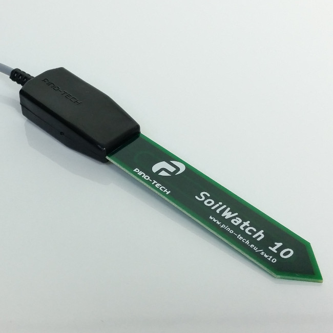
SoilWatch 10 soil moisture sensor designed to work with Arduino. Easy to use. Can also be used with RPi if used with an external ADC.
fierce apex
water sensor - 2 pieces coat hanger and alligator clips and speaker wire to DVM to look at it
if i can see a pattern maybe just a comparator
when dry --- beep
dont know the feed back loop to water - i imagine overwatering a plant easy to do
fervent lance
fierce apex
water sensor - 2 pieces coat hanger and alligator clips and speaker wire to DVM...
depends on how reliable this is
fierce apex
my water sensor for now is my finger - want to update
fervent lance
fierce apex
dont know the feed back loop to water - i imagine overwatering a plant easy to d...
easiest setup: have soil moisture sensor, read its value periodically (every 5 min or so) and see if moisture is below the threshold. if its not, do nothing, if it is, then open valve / power pump / whatever for a fixed amount of time. you might be going well over the threshold, but that is not bad, as long as there is enough time for the substrate to dry below the threshold before the next irrigation cycle happens
fierce apex
i have a 17 yr old orchid - i dont trust to automated watering
fervent lance
fierce apex
i have a 17 yr old orchid - i dont trust to automated watering
i would not trust that to a computer haha
fierce apex
i have a bunch of aloe vera i , ignore them - seem to do well
fervent lance
fervent lance
easiest setup: have soil moisture sensor, read its value periodically (every 5 m...
irrigation time muss be lower than sensor read intervall of course
fierce apex
low sample rate to allow - water to drain
fervent lance
fierce apex
i have a bunch of aloe vera i , ignore them - seem to do well
they like it dry, dont they? 😄
fierce apex
aloe vera love crowded pots -- one vera in a pot withers
fervent lance
fierce apex
low sample rate to allow - water to drain
nah, as long as you are above the threshold, you should be adding more water. you should still read you sensor value
fierce apex
hmmm wondering..... have a data logging setup - then i do the human thing by hand - and refer to data to see if anything
hmm i can imagine - many configurations of water sensors , besides 2 coat hanger bits
humidity does have a correlation
and temp
fervent lance
i dont quite understand what you are trying to say?
fierce apex
i have a habit of making it , overly complex - im trying to simplify
pino tech , 75 Mhz - its a ANtenna ?
the water in the soil changes the permeability arount ANT ?
ohhh capacitive
fervent lance
its for arduino
might be c, might be c#
there are also other professional sensor, but the are waaaay to pricey for a hobbist:
https://www.metergroup.com/en/meter-environment/products/teros-12-soil-moisture-sensor
https://www.truebner.de/de/smt100.php

METER
The all-new TEROS 12 soil moisture sensor delivers an excellent price-to-performance ratio in a device that is easy to use and includes electrical conductivity.
fierce apex
10 bits = 1024 ADC
fervent lance
fierce apex
10 bits = 1024 ADC
yea, should be enough. I use mine with 16 bit adc i think
fierce apex
thats a new sensor - i wanna take it apart
3rd electrode is a ? , is this still capacitive
70 Mhz........ something
 woven pasture
Hi All, couldn't find exactly the correct channel to ask, but this one seemed to be the closest.
Can anyone tell me what this type of interface connector is called?
 long wraith
I think that’s a mezzanine connector
woven pasture
Thanks for the lead, I think you're almost right. Mezz connectors ( IEEE 1386 ) appear to have the contact pins symmetrically mirrored.
A quick search and I haven't been able to find a mezz connector with those triangular keyed edges, and offset pins
long wraith
Hmm… might be proprietary
That looks like a TPM module from a PC? A lot of the ones that don’t use regular 2x(n) 0.1” headers use proprietary connectors so you can’t just use any module
woven pasture
You're spot on there! It's a TPM from Tyan and I cannot find a supplier anywhere, so I was going to make my own "translation" board so I could piggy-back a TPM from another OEM
The pin-out for the Infineon TPM over SPI is super simple. The OEM's make it difficult to lock you into buying their AICs
long wraith
I find the situations with TPMs to be infuriating... But personally I'm disabling fTPM on my devices that have it and not putting TPMs into ones that don't so Microsoft can't "accidentally" "upgrade" my computers to 11
distant raven
long wraith
I find the situations with TPMs to be infuriating... But personally I'm disablin...
The second the “accidental” upgrade happens I’m moving to Linux Mint
woven pasture
long wraith
I find the situations with TPMs to be infuriating... But personally I'm disablin...
🤣 fair.
I'm building a new NAS and wanted to try out systemd's relatively new measured boot, cyptysetup auto unlock
long wraith
distant raven
The second the “accidental” upgrade happens I’m moving to Linux Mint
Can't happen if the computer isn't compatible 
distant raven
Yeah true
long wraith
woven pasture
🤣 fair.
I'm building a new NAS and wanted to try out systemd's _relatively_ n...
Ahh... that's fair
woven pasture
At this point I think I'll just test it out with my YubiKey
distant raven
I need to disable fTPM at some point
I have a YubiKey for work, seems to work great
long wraith
I disabled fTPM on my systems as soon as I found out Windows 11 had a TPM requirement
twin hedge
unreal flax
Watch out for USB power limits. A RasbPi4 can suck down 3A or so.
I know, which is why I don't wanna use a Pi. I can't even use it because it doesn't have energy RAM to load the model.
woven pasture
distant raven
I have a YubiKey for work, seems to work great
Same. Also Apple has enabled 3rd party FIDO2 (aka Yubi) associations on AppleIDs. So that's helpful when you don't want to get locked into PassKeys
twin hedge
balmy tide
Why not 2 separate devices? A simple mcu acting as hid, communicating with a com...
I see what you mean. For example, The Linux on the USB could output GPT-J's output over UART, and the MCU could take that and output it over USB as keyboard input.
distant raven
Apple doesn’t support hard tokens for MFA windows connections though which is sad. Not through the Microsoft RDP app anyway. You have to use some kind of VDI client like Citrix which is a pain
woven pasture
distant raven
Apple doesn’t support hard tokens for MFA windows connections though which is sa...
Yup! I know that pain also.
distant raven
And Microsoft broke but won’t acknowledge they broke RDP on windows 11 with it randomly switching to UDP when my employer’s servers only allow TCP/IP sessions
It was kind of broke in 21H2 but then broke broke in 22H2
Found that out the hard way
long wraith
And THAT kind of random crap is why I refuse to implement 11 in my environments
twin hedge
Same.
 still cypress
Working on a design for a PCB that powers some 24v fans (one of them is a bit of an odd fan) and some thermistors for a project I'm working on. It's meant to run on a kb2040/rp2040 pro micro/Boardsource blok. Before I get much further with the design, was hoping someone could spot check any obvious mistakes. First time using kicad, and not super familiar with electronics, but that's never stopped me before!

 dry pelican
Looks good, but what’s going on with the weird zener thing with PWM on the roborock fan? (Also, it seems like you called Schottky diodes Shockley diodes (after one of the inventors of the transistor))
twin hedge
Could this do for the processor I'm looking for?
https://www.digikey.com/en/products/detail/nxp-usa-inc/MIMX8MN6DVTJZAA/10669045
unreal flax
twin hedge
Could this do for the processor I'm looking for?
https://www.digikey.com/en/prod...
Well, the usual reply to, "Is this 500-pin, gigahertz chip what I want to use?" is: "If you're even asking that question the answer is 'Oh god, nope nope nope!'..."
dry pelican
That thing has some insane specs and is extremely pricey
I would use something where you won’t have to brew your own VRMs, high frequency length-matched, loop-optimized, high frequency traces, a 12 layer PCB, and your own software support. And I can imagine soldering that thing will be a nightmare.
I would just get an SBC that has the specs you need. There are some powerful pi alternatives out there.
And it doesn’t seem to have a datasheet
still cypress
dry pelican
Looks good, but what’s going on with the weird zener thing with PWM on the robor...
I was tired when I wrote that. Felt wrong haha. The Zener thing for this. https://github.com/condottab/Roborock-CPAP
 rustic linden
CPAP as in the therapy for sleep aponea?
distant raven
dry pelican
I would use something where you won’t have to brew your own VRMs, high frequency...
Boards would be expensive, you could probably do 6, maybe 8 layers at most with via in pad and 3/3mil trace-spacing.
Length matching isn’t terribly difficult, just time consuming
still cypress
rustic linden
CPAP as in the therapy for sleep aponea?
Yup. Repurposed for 3d printers
distant raven
Get the ones with the open patterns on the bottom of the die
 tulip topaz
still cypress
I was tired when I wrote that. Felt wrong haha. The Zener thing for this. <https...
tulip topaz
still cypress
I was tired when I wrote that. Felt wrong haha. The Zener thing for this. <https...
By doing a low side mosfet switch on the fan, you won't have ground tied to that pwm circuit when mosfet0 is off. Could be an issue.
I'd tie it to gnd, not mosfet0/-24v.
Your motor snubber diode is wired wrong
still cypress
Motor snubber diode?
tulip topaz
The schottky, should connect across the motor leads, pointing up. Also known as flyback diode.
Its wired in series, no reason for that. The github link shows it wrong too.
still cypress
It PWM's on GND and has to PWM along with the PWM signal due to how the fan board that connects to it works. It's intentionally disconnecting that for reasons that the designer of that bit of the circuit understands that I don't.
It fails when not switched, that's the extent that we know.
tulip topaz
Your board has the luxury of a full time ground. Condotabb is applying some band-aids since his gnd is coming and going with pwm. When his pwm is off, everything tied to gnd will float up to 24V hence all those zeners and schottky diodes.
Plus he is bringing in a pin from a motherboard without a ground reference.
I'm guessing the motor needs a 0-5v pwm signal.
dry pelican
I forgot about flyback diodes. I'm not sure if brushless fans have them integrated (with the little controller IC), but it's good to have them so inductive current spikes don't kill your mosfets. I'm not sure what current rating to go for, but I would go for diodes with a continuous current rating of the current you're running the motors at to play it safe.
tulip topaz
dry pelican
I forgot about flyback diodes. I'm not sure if brushless fans have them integrat...
Diodes just need to handle the flyback spike, add a resistor to help clamp it, but a few amps should be fine, size up if it pops.
tulip topaz
still cypress
It PWM's on GND and has to PWM along with the PWM signal due to how the fan boar...
You will need a 5v regulator and a level shifter for the pwm. You need 3.3V, not seeing that in your schematic.
still cypress
tulip topaz
You will need a 5v regulator and a level shifter for the pwm. You need 3.3V, not...
It's coming from the MCU
still cypress
dry pelican
I forgot about flyback diodes. I'm not sure if brushless fans have them integrat...
I've got a flyback on one section. I'll apply it to everything. Thanks.
 woven bluff
 tulip topaz
Electrically it won't matter, but if you care about adjustment direction being CW vs CCW, it will.
 nova drift
How dangerous are LiPo batteries? Are they more dangerous than phone batteries?
distant raven
Phone batteries typically are LiPo or Li-Ion
unreal flax
nova drift
How dangerous are LiPo batteries? Are they more dangerous than phone batteries?
Phone batteries are typically also LiPo, so pretty much the same, give or take packaging and protection circuits. There's a spectrum of dangerous depending on the current rating, too... high-power LiPos designed for drones and airplanes can put out a lot of current.
distant raven
And puncturing is bad regardless of capacity
Toxic fumes, fire, etc.. are common dangers of mishandled Lithium batteries
long wraith
“Dangerous” also depends on what you mean. Aforementioned toxic fumes and fire are going to be similar risks between a phone battery and pouch style cells if both are safely inside a device. 18650 or solid cells like those are a bit more resistant to damage, but equally likely to burst from a short without protection.
nova drift
unreal flax
Phone batteries are typically also LiPo, so pretty much the same, give or take p...
So something like Adafruit's 400 mAh Feather-sized battery inside an enclosure connected to a Feather is as safe as a phone?
nova drift
long wraith
“Dangerous” also depends on what you mean. Aforementioned toxic fumes and fire a...
It will be inside an enclosure of some kind (I haven't decided how to build the enclosure yet, but it will have one), and a short is very unlikely because it will be connected directly to a Feather board.
nova drift
distant raven
And puncturing is bad regardless of capacity
It will be protected from punctures
nova drift
 elder peak
https://tenor.com/view/battery-explosion-explode-explodes-unboxing-gif-26046605
elder peak
https://tenor.com/view/battery-explosion-explode-explodes-unboxing-gif-26046605
Why would someone do that‽
long wraith
nova drift
It will be inside an enclosure of some kind (I haven't decided how to build the ...
It’s relatively safe then. Just always remember to treat batteries with respect and care. Don’t leave your project in the sun!
nova drift
long wraith
It’s relatively safe then. Just always remember to treat batteries with respect ...
Okay, I'll do that. Would carrying it in a pocket be okay if the case is sturdy enough?
long wraith
nova drift
Why would someone do that‽
That’s hopefully fake, but some people have no idea how dangerous punctures are, and might want to see what’s inside…
long wraith
nova drift
Okay, I'll do that. Would carrying it in a pocket be okay if the case is sturdy ...
Mhmm, if it’s nice and safely enclosed, it’s safe as a phone
 humble swift
I watch some RC channels and the cavalier way they handle LiPo batteries CONCERN me
nova drift
Okay, great! I'll definitely be careful, but it's nice to know my ham radio pager won't randomly explode.
long wraith
Chances of random explosion are about the same as any phone, generally — so unlikely
humble swift
Make sure any battery you get has the appropriate protection circutry, some very cheap ones dont come with it
the adafruit ones do obviously
nova drift
I'll be using Adafruit batteries
humble swift
Good call, i bought a cheap one off ebay and then found out that it needed the circuit, by the time i bought and installed it i paid more than just buying the adafruit one -.-
elder peak
If you watch Bigclive on YouTube he's got the explosive battery containment pie dish.
nova drift
What is the best way to put a power switch on a Feather with a LiPo?
I'm fine with soldering
distant raven
nova drift
What is the best way to put a power switch on a Feather with a LiPo?
Are you simply looking to turn off the device as a whole?
nova drift
Yeah, to turn the whole thing on and off
Behavior when the switch is turned off with USB connected doesn't matter
distant raven
You can wire a switch between EN and GND on most boards
The en pin going to ground would turn off the regulator
nova drift
So the switch would actually go "on" to turn the board off?
distant raven
Right
nova drift
Okay, that would be fine
 young jacinth
hello friends! i'm super new to hardware design (i actually... don't know almost anything about circuits, even though i fab them for my internship). what i'm looking to do is to create a programmable LED matrix for a thomas bangalter daft punk helmet. are there any recommendations on what I should buy? having the display be see through is very, very helpful, but if there's no good way to do it, i could always be fine with not having that
nova drift
Is there any power consumption when the board is off?
distant raven
You could still charge the LiPo but you’d turn it off to use the microcontroller with usb
Turning the regulator off should just leave you with a small amount of quiescent current
nova drift
So the LiPo would charge at either setting?
distant raven
Right
nova drift
Okay, a small amount is fine
distant raven
The LiPo charger will also leak a small amount as well, maybe a few dozen uA
nova drift
What would happen if you plugged it into a computer with the switch set to turn the board on?
distant raven
So if the switch was open?
nova drift
Yeah, with the switch open
distant raven
The regulator would turn on when it got USB/battery power
nova drift
So when it's connected to a computer or other power source by USB, the setting of the switch wouldn't matter?
distant raven
No it’s going to matter
The regulator powers the micro
So if it’s not enabled you’ll only power the charger
nova drift
Oh okay
So for charging it can be on or off, but for reprogramming it needs to be on?
dry pelican
young jacinth
hello friends! i'm super new to hardware design (i actually... don't know almost...
There are transparent OLEDs (HUD and pixels), but they are expensive and they're not really fit for a matrix with big dots. A gas discharge tube matrix would be cool, but it would require custom <pretty much everything>, and it would put high voltage very close to your face.
distant raven
nova drift
So for charging it can be on or off, but for reprogramming it needs to be on?
Yeah, the regulator needs to be on
worldly schooner
young jacinth
hello friends! i'm super new to hardware design (i actually... don't know almost...
https://learn.adafruit.com/3d-printed-daft-punk-helmet-with-bluetooth/overview might be a good place to start haha

Adafruit Learning System
Build a Daft Punk Thomas Helmet with bluetooth control!
humble swift
I have a question, assuming the fault with this ESP32 feather v2 is that the usb-uart bridge doesnt work, is there any way to bypass that and program it anyway?
young jacinth
worldly schooner
https://learn.adafruit.com/3d-printed-daft-punk-helmet-with-bluetooth/overview m...
could there be a way to make multiple strips and a program to program each?
worldly schooner
humble swift
I have a question, assuming the fault with this ESP32 feather v2 is that the usb...
Assuming that is the case, you can solder some wires to the tiny pins on the ch9102f chip to connect to an external usb uart converter or other serial-capable device.
humble swift
spicy
worldly schooner
young jacinth
could there be a way to make multiple strips and a program to program each?
You wish to program each strip independently? A single microcontroller can handle pretty much as many of these addressable neopixel LEDs as you can power.
young jacinth
ah, i mean to link all of those strips into a grid haha
maybe i could just twist and turn the strip a bunch and see if i could make it into a grid?
young jacinth
young jacinth
maybe i could just twist and turn the strip a bunch and see if i could make it i...
worried about the flexibility of this, though, as flex boards are really rough
worldly schooner
You can arrange them in a grid, sure. Probably easiest to just use horizontal rows and connect the ends.
With wires or something
This project uses two rows, but theoretically you can use as many as you can fit in the visor. Hopefully you can still see between the rows, though.
young jacinth
i could definitely do something like that! is the connection just two copper bits?
(as in, like, how many traces are there to connect?)
worldly schooner
Three. Power, data, ground.
Direction matters for data, make sure not to connect two data ins or two data outs together.
nova drift
Is it normal for a Raspberry Pi Pico PWMing a pin to make a very quiet, high pitched hum? I have to hold it to my ear, but I can hear it.
It's underclocked to 18 MHz
young jacinth
worldly schooner
Direction matters for data, make sure not to connect two data ins or two data ou...
got it. may i send a garbage ms paint diagram of what i'm thinking?
worldly schooner
Sure, why not.
nova drift
nova drift
It's underclocked to 18 MHz
It only happens when underclocked
young jacinth
perhaps the underclocking is the issue, then?
worldly schooner
nova drift
It only happens when underclocked
If your PWM frequency drops to an audible range as a result of your underclocking, a hum would not be surprising.
nova drift
worldly schooner
If your PWM frequency drops to an audible range as a result of your underclockin...
The know! So it's not any cause for concern?
*thank you
tulip topaz
nova drift
The know! So it's not any cause for concern?
Not usually a concern, it depends on what you are sending the PWM to.
Set your PWM freq to 20khz (or anything above 16khz, depending on your age), you will no longer hear it.
 pale umbra
that was like one of the first project
determine my range of hearing and my fps range with an arduino 😄
dry pelican
Cheap gadgets sometimes have a very low pwm freq (like 1-2kHz or maybe even lower). The noise is very annoying when you try to dim the pwm controlled thing
dry pelican
No. I think that would be pretty normal
Otherwise every single led light would appear to flash
Mains powered
worldly schooner
Can’t see individual frames at 60fps, so that’s more than reasonable
dry pelican
eye fps is limited by the speed at which the receptors reset (since it's all chemistry), which leads to persistence of vision
worldly schooner
A lot of LED projects recommend 400hz since there’s little chance of anything audible compared to motors or inductors
 sleek ice
I need an 80mm (preferably) or 3 inch round display without an octagonal backlight and bulk. Can anyone find that? I've looked all over aliexpress.
humble swift
dang, only one i can think of is 2.1
worldly schooner
sleek ice
I need an 80mm (preferably) or 3 inch round display without an octagonal backlig...
That’s an oddly specific request. Does https://www.aliexpress.us/item/3256804678255758.html work?
sleek ice
worldly schooner
That’s an oddly specific request. Does https://www.aliexpress.us/item/3256804678...
That's 3.4 inch
worldly schooner
I see 3.4 and 2.8. If you need something exactly 3.00-3.15” you might need to custom order…?
There are a lot of 1.28” for smart watches, and a lot of 3.5”-5” for VR applications, anything in between has far less demand to have significant market share.
I’m surprised 2.8” even exists off the shelf, to be honest.
sleek ice
Okay. I might have to
worldly schooner
sleek ice
I need an 80mm (preferably) or 3 inch round display without an octagonal backlig...
3 Inch Round Ips Tft Lcd Display High Brightness 432x432 Resolution - Buy 3 Inch Round Ips Tft Lcd Display,High Brightness 432x432 Resolution For Small Size,3 Inch Round Ips Tft Lcd Display High Brightness Product on Alibaba.com
sleek ice
Too large of an outline
worldly schooner
What exactly is this for, anyways? Do you need these in bulk for a product, or is this a personal project?
sleek ice
Personal project. Basically trying to replace the Gamecube jewel with a video display
rustic linden
Smaller with a border might do fine
sleek ice
Was thinking this https://m.alibaba.com/product/1600477213243/2-8-Tft-Display-2-8.html?s=p
2.8 inch 480x480 round IPS LCD high brightness all viewing angle tft module screen LCD display panel, You can get more details about from mobile site on m.alibaba.com
But I need a controller board. Any suggestions?
nova drift
What are the rectangular holes in the bottom of the Feather cases for?
And why are the cases quite a bit wider than seemingly needed?
Oh it looks like it's to allow connecting a battery cover?
sleek ice
nova drift
A Feather with a 400 mAh battery should fit inside https://www.amazon.com/Zulkit-Project-Plastic-Electrical-Junction/dp/B07Q11F7DS/, right?

Zulkit 5Pcs Project Boxes ABS Plastic Electrical Project Case Power Junction Box Black 2.40 x 1.41 x 0.98 inch (61 x 36 x 25 mm)
(I know the mounting holes won't line up; I'll use hot glue or two-sided tape)
nova drift
I just thought, the charging port will be hard to access.
Although I could have the board raised up in the lid
A way to plug it in without opening it would definitely be better
nova drift
Probably not, but would sandwiching the Feather and battery between sheets of styrene and wrapping it in electrical tape be enough protection?
worldly schooner
nova drift
A way to plug it in without opening it would definitely be better
https://www.adafruit.com/product/4218 might be useful.

If you need to add a panel-mount connection but don't have the time or ability to cut a custom oval or square hole, this USB C Round Panel Mount Extension Cable is the ...
Oh, wait, those enclosures are tiny.
Hm.
nova drift
worldly schooner
Oh, wait, those enclosures are tiny.
I could use a larger enclosure if necessary.
Oh, that cable is a bit too expensive.
I'll look to see if I can find anything comparable cheaper.
I really only need charging; it's okay to take it apart for reprogramming. A dedicated external adapter for charging is okay. Does that simplify anything?
Is the "USB" pin on the Feather 5V USB power in?
unreal flax
nova drift
Is the "USB" pin on the Feather 5V USB power in?
You may need to specify which Feather you mean, since there are a number of boards by that name.
nova drift
It's the Feather RP2040.
unreal flax
Yep, from the schematic the USB pin is connected directly to VBUS 5V on the USB connector.
nova drift
Okay, thank you! So if I use some kind of connector to connect "USB" and "GND" to the positive and negative wires of a USB cable, that will charge it?
unreal flax
I mean, it should, but if you're using a USB cable already, is there some reason you wouldn't want to just use the existing USB connector instead?
nova drift
A round connecter would be easier to get through the case because then I could drill a hole
unreal flax
Ah, gotcha.
nova drift
I'm thinking about using https://www.adafruit.com/product/368 held in place with hot glue

If you need to connect a DC power wall wart to a board that doesn't have a DC jack - this adapter will come in very handy! There is a 2.1mm DC jack on one end, and a screw terminal block ...

This power jack is designed to easily attach to a panel up to 8mm thick (0.315" or 5/16") and fit 2.1mm power plugs snugly and securely. Perfect for adding a power connector to ...
I'll probably do that; it's made for panel mount use and only $1 more
It looks like all the connectors I need are available in panel mount versions fairly cheaply

Other than the case and a 3.5 mm to 2.5 mm stereo cable, both of which are cheap on Amazon, everything is available from Adafruit
Does it hurt Adafruit LiPo batteries to drain them to the point where the protection circuit shuts them off?
sleek ice
Where can I find an extended ribbon cable for this? What would even be the technical term for it? https://m.aliexpress.us/item/2255800358721473.html?spm=a2g0n.shopcart.0.0.5d9838dashq9gZ&mp=1&gatewayAdapt=gloPc2usaMsite&_randl_shipto=US

I think it's a 40 pin 0.5mm pitch but idk
worldly schooner
sleek ice
Where can I find an extended ribbon cable for this? What would even be the techn...

Give your 40 pin, 0.5mm pitch, devices a strrrreeeetch with this extension board. This 40pin FPC extension board has two 40-pin flex connectors (both are bottom contact type), and an ...
twin hedge
Would this processor work for my needs?
https://www.digikey.com/en/products/detail/nxp-usa-inc/MCIMX6Z0DVM09AB/9687787
distant raven
twin hedge
Would this processor work for my needs?
https://www.digikey.com/en/products/deta...
I recommend looking at AllWinner SoC
They come in packages that are actually usable for the average person
BGA tends to requires lots of advanced techniques in routing and expensive board manufacturing processes
worldly schooner
Imx6 is a solid processor with a lot of support, but I don’t think off the top of my head I could tell you if it could run a chatgpt instance.
distant raven
Plus they tend to have lower yield because it’s harder to fix electrical issues under the chip after it’s soldered
worldly schooner
It’s pretty common in commercial devices, but not exactly accessible to hobbyists.
I know they have system-on modules available for this processor though. Doesn’t help with your unusually high memory requirements, but could ease development costs otherwise.
distant raven
Definitely look at Octova I think is the brand
They have very nice SoM with big pitched BGA
worldly schooner
Octavo iirc
distant raven
Yeah
worldly schooner
Do they do MPU sips?
twin hedge
worldly schooner
Imx6 is a solid processor with a lot of support, but I don’t think off the top o...
Not ChatGPT. I'm talking about GPT-J. It can be ran offline.
distant raven
twin hedge
Not ChatGPT. I'm talking about GPT-J. It can be ran offline.
There’s raspberry pi 3 A+ in stock
If you want to grab one

NOTE: Due to stock limitations we may only be able to offer refunds or store credit for Pis that are defective, damaged or lost in transit.The Raspberry Pi 3 Model A+ is the latest ...
30 right now
Just above 10 now
twin hedge
I need a minimum of 16GB of RAM. This won't do.
twin hedge
distant raven
There’s raspberry pi 3 A+ in stock
I'd use my Pi if I could, but I can't. Besides, I plan on making this a USB that plugs into a computer, so the power draw wouldn't be ideal.
worldly schooner
GPT-J
distant raven
Is that what they suggest?
worldly schooner
I think he’s trying to load the full model into memory
I think most applications use gpu ram though
distant raven
I think he’s misunderstanding the requirements
16GB VRAM
Many models want 32GB or more of RAM on top of that
You’re not going to get that in a PCB that’s easily designable or manufactured
Just being realistic here, you will need a GPU, CPU, etc..
twin hedge
distant raven
16GB VRAM
I believe I can use CPU RAM. This is only after adding an argument to the model and using the float16 branch to get the model's requirements to 12.1GB.
distant raven
All that is going to take months to design a USB ready device assuming you’ve done the design to get that
My understanding is 12.1GB is just the size of the instance not the resources needed.
worldly schooner
I don’t see a capable cpu being able to operate as a bus-powered device. At least not with our current generation of hardware.
distant raven
Yeah
If you find something that can do PCIe over USB C and have a host that can do that as well, sure maybe
twin hedge
Why would I need PCIe?
distant raven
Not trying to be a killjoy but something like this would take a team of 2-3 experienced engineers a couple months to do.
distant raven
twin hedge
Why would I need PCIe?
Because of Hem’s mention above
twin hedge
So I can use a processor capable of running the model?
distant raven
I would find a small gaming PC with a dedicated graphics card
GPT-J appears to heavily rely on GPU power
worldly schooner
udoo bolt comes to mind
I just checked coral dev board, even that only goes up to 4gb
And that’s designed for machine learning
distant raven
Yeah
worldly schooner
We’re talking an application that traditionally requires a cloud hosted server to run properly
I don’t mean to be a Debbie downer, but I think this needs a lot more research before you start shopping for hardware
Even most standard PCs wouldn’t be able to do this, and you’re trying to squeeze this into a thumb drive haha
distant raven
It would probably get thermally throttled right away
worldly schooner
I think the biggest issue is the number of constraints you’re setting for yourself right from the get-go. Before jumping into MPUs and RAM, start with some feasibility studies. See if you can run this on your home desktop before trying to go smaller. Approach this as a multi-part problem and go one step at a time.
What hardware do you have that successfully runs this model? How much memory does it use in practice? How much power is it drawing? How fast is it running? How can I reduce the hardware requirements with minimal performance impact?
I admit I didn’t really think about what you were trying to do when you first brought it up, but these are all important design steps that all contribute to a successful design.
distant raven
And also evaluate how your own skill level in designing things to.
Some of these parts require quite a bit of experience to route and use in manufacturing. Plus the cost for a few one off boards might be more expensive that simply going with an off the shelf solution
long wraith
… NVidia Jetson? I dunno what the whole project is, but I know Jetson can come with large amounts of RAM for training models and stuff, and the Nano can be had for under $200
worldly schooner
Right, but the nano doesn’t go up past 4gb ram. Jetson Orin might manage, though.
Only 721 for the module.
distant raven
Yeah
Looking, a lot recommend running GPT-J in VRAM because it tends to be better optimize for the tasking
worldly schooner
Add a minimal carrier board and we have something that might meet the specs and is only a little bigger than a lattepanda.
distant raven
LattePanda ahhh such a great board
Someone shoved a Zynq 7000 on a feather so maybe Pi Zero W sized if you really know what you’re doing
worldly schooner
Still uses like 10W min, not something you can provide to a USB peripheral. Maybe usb-c or thunderbolt…
long wraith
worldly schooner
Right, but the nano doesn’t go up past 4gb ram. Jetson Orin might manage, though...
Oop, I thought it had 8 and 16GB versions… might have been thinking of the Orin
twin hedge
So where should I start? Build a gaming PC? Get a Linux SBC?
long wraith
What’s your end goal?
Like, what do you want to do with ChatGPT-J that you were thinking of building your own SBC?
twin hedge
long wraith
Like, what do you want to do with ChatGPT-J that you were thinking of building y...
It's only GPT-J, since it's not forked from ChatGPT. I was hoping for something possibly like a portable assistant. It could write code, generate essays, etc. I'm not completely sure how to put my end goal into words.
long wraith
Ahh. I’d say if you want to do any software development before deploying, start on your PC; but for portable, I’d just find an existing SBC instead of trying to create your own
 supple pollen
There are USB neural accelerators like https://coral.ai/products/accelerator
twin hedge
long wraith
Ahh. I’d say if you want to do any software development before deploying, start ...
My PC isn't capable of doing so.
long wraith
twin hedge
My PC isn't capable of doing so.
I'd consider the USB accelerators that madbodger mentioned; then you can use it on a smaller/cheaper SBC like a Pi Zero
twin hedge
supple pollen
There are USB neural accelerators like <https://coral.ai/products/accelerator>
Would I need multiple?
long wraith
Probably just one would do it? But more is faster
twin hedge
long wraith
Probably just one would do it? But more is faster
I have access to one. How would I set it up with GPT-J though?
long wraith
That's a bit past my knowledge -- but usually the configs for such models allow selection of accelerators
Or some automatically provision and use available accelerators and GPUs
young jacinth
@worldly schooner new idea, clear me on this if i'm wrong, but could i grab a bunch of those old red dot leds and address them by writing some arduino code?
twin hedge
long wraith
Or some automatically provision and use available accelerators and GPUs
Is it possible for me to use a Raspberry Pi 4 (8GB) and a Coral USB Accelerator to run the model?
long wraith
Should be able to!
twin hedge
How would I write the script? What all do I need to do?
long wraith
Like I said, past my knowledge -- I haven't used GPT-J or USB accelerators
worldly schooner
young jacinth
<@98211350907490304> new idea, clear me on this if i'm wrong, but could i grab a...
The matrices? Sure you can, but I don’t know if that saves you money or time.
young jacinth
not the matrices, just pure old school dot leds
worldly schooner
Regular LEDs don’t have “addressing” so you would need extra hardware to control a large number of them
A lot more wiring and complex design, too. The LEDs themselves are cheap, but you’re on your own when it comes to controlling them.
young jacinth
ah, i see
twin hedge
At some point, I plan on getting a laptop I can use for development (e.g Unity, LFS, etc.) and maybe some gaming. Once I get one, I can possibly get the model running on it.
supple pollen
young jacinth
<@98211350907490304> new idea, clear me on this if i'm wrong, but could i grab a...
You can address them by putting them in a matrix, or more of them (with more difficulty) by "Charlieplexing" them. You can also use an outboard chip to do either of these for you.
balmy tide
TL. DR. Do i need to worry about how much power this type of shunt resistor dissipates?
I am building a soldering iron, pretty common thing hakko 907 clone iron controller. I want to measure current, to simply calculate power. I want to use this shunt resistor (combination with a low pass filter to average out PWM), and couldn't decide on value. I am using 20V supply so full-on peak current is 5A, and when hot it's close to 3A. With 50m shunt peak power is 1.25W. According to conversations we had before here, I also need to consider signal to noise ratio. I will have to use low pass filter so I don't think there will be issues about that. What power should I aim for shunt resistor dissipation?
My choices are 2m, 5m, 10m, 20m, 30m, 50m, 100m, 120m, 150m, 200m, 300m, 500m. Open to suggestions but I would like it more if I learn to make decision myself.
 fervent lance
Quick question regarding RGBW-Neopixels. If i just want to run one of the colors or white on full power, but no mixes of colors, is a JST XH-Connector (max 3A) safe to use for the NeoPixel Matrix (64 LEDs)?
Are the 80mA / pixel-figure mentioned in the Überguide on the website for ALL colors and white on full blast at the same time?
 latent jungle
fervent lance
Are the 80mA / pixel-figure mentioned in the Überguide on the website for ALL co...
latent jungle
fervent lance
Are the 80mA / pixel-figure mentioned in the Überguide on the website for ALL co...
20mA per color.
balmy tide
fervent lance
Are the 80mA / pixel-figure mentioned in the Überguide on the website for ALL co...
yes, and should be fine.
latent jungle
For reference, Estimating Power: https://learn.adafruit.com/adafruit-neopixel-uberguide/powering-neopixels
distant raven
Thanks! You’re retro rebuilds/repurposing has given me some ideas for my SEGA genesis
I have no idea if it works in its current condition though ha
latent jungle
They’re pretty robust. Start with a recap and clean the cartridge port.
distant raven
I plan to convert the power supply to USB C in the process
Make it easier to power in the future since I don’t plan to re home it
latent jungle
That would be cool to see.
distant raven
I need to find some games too, all the ones I had from years ago are long gone
supple pollen
balmy tide
TL. DR. Do i need to worry about how much power this type of shunt resistor diss...
You seem to understand the tradeoffs: lower value = less heat and more efficiency, but a lower level signal out. Higher value gives a stronger signal, but more heat and lower efficiency. For a 3-5A range, and the 50mΩ value you mention, that would give 150-250mV signal, which seems workable.
fervent lance
latent jungle
20mA per color.
Thank you!
fervent lance
balmy tide
yes, and should be fine.
Thank you!
balmy tide
supple pollen
You seem to understand the tradeoffs: lower value = less heat and more efficien...
thank you
dry pelican
supple pollen
You seem to understand the tradeoffs: lower value = less heat and more efficien...
What do you mean by efficiency? I thought that a resistor dissipates all its power by heat, and therefore is 100% efficient at producing heat or energy that ultimately becomes heat.
young jacinth
supple pollen
You can address them by putting them in a matrix, or more of them (with more dif...
just started researching this, tysm
latent jungle
dry pelican
What do you mean by efficiency? I thought that a resistor dissipates all its pow...
Probably meant system-level efficiency.
dry pelican
Maybe. That would make sense
balmy tide
The heat will be dissipated on shunt resistor away from soldering iron's heater core
dry pelican
For some reason I was thinking it was a shunt and heating resistor. But in hindsight that really does not make sense
balmy tide
It makes sense but you have to know temperature coefficient of resistor. Not really reliable way of doing for a no name Chinese clone
supple pollen
That's why I was thinking of skipping the shunt entirely and just measuring the drop over the heating element instead. Granted, it's going to be a higher temperature range and would likely require correction, but it's simple enough to measure the values to build the coefficients.
dry pelican
resistance does increase with heating, so it could also be possible to measure the temperature that way
you could tap the heating element to effectively create a shunt
supple pollen
That too. However, a tap wouldn't add much information if the entire element was at the same temperature.
dry pelican
a tap could measure current though. And wouldn't require a hot shunt
dry pelican
balmy tide
It makes sense but you have to know temperature coefficient of resistor. Not rea...
Maybe you can measure it. But that would take some precision equipment
although I think it's just based on material, so you could make an educated guess and see if it works out
supple pollen
I don't really see how a tap could measure current in this situation, but just measuring the voltage across the element could, once you'd determined the thermal coefficient.
 ocean coyote
hey everyone, looking to buy a couple of pico w's but im not a fan of the micro usb port, im either looking for a clone of the product or a usb c connector that has 5 pins to work in place of the micro usb port
i found these online but idk

Partsbaba
USB 3.1 Type-C Female USB Connector SMD 5Pin U262-061N-4BVC11
rustic linden
Since it doesn't have a datasheet or any such, there's ultimately no way of knowing entirely other than purchasing them and testing them out
ocean coyote
yeah
when i go to order them, there is no where to change country
and its set to india
if anyone knows of another website with them give me a ping
long wraith
ocean coyote
hey everyone, looking to buy a couple of pico w's but im not a fan of the micro ...
Here’s a very similar board to the Pico with a C port https://www.waveshare.com/rp2040-plus.htm
RP2040-Plus, A Low-Cost, High-Performance Pico-Like MCU Board Based On Raspberry Pi Microcontroller RP2040
Oh, wait, you said W, oops…
ocean coyote
long wraith
Here’s a very similar board to the Pico with a C port https://www.waveshare.com/...
no worries
worldly schooner
ocean coyote
hey everyone, looking to buy a couple of pico w's but im not a fan of the micro ...
As much as I would agree on the micro vs c, I’d be skeptical of using a 5-pin usb c connector unless it somehow handles the cc resistor terminations internally somehow.
rustic linden
that's not impossible, though
worldly schooner
No, but I expect them to be decently expensive haha
ocean coyote
worldly schooner
As much as I would agree on the micro vs c, I’d be skeptical of using a 5-pin us...
you make a good point
and i cant get the ones i linked above
they only sell within india
distant raven
For Wi-Fi with RP2040 you could use the Challenger RP2040
Tindie
Raspberry Pi Pico board with 8Mbyte Flash and integrated WiFi
 compact frigate
Somebody with an RP2040, could you please run the following snippet in order to find out which pin combinations support PDMIn: https://learn.adafruit.com/adafruit-pdm-microphone-breakout/circuitpython#wheres-my-pdmin-3038798

Adafruit Learning System
From Sound Pressure to Pulse Density Modulation
balmy tide
I think you are more likely to find help on some other channels. Maybe #help-with-circuitpython
The project I'm taking inspiration uses mcp602, but I have access to some mcp6002 in my uni lab so thats what i will be using. But this made me think, is there any reason to use mcp602 instead of mcp6002? It looks like almost virtually every aspect is same or better with lower cost, am I missing something in comparison between two?
https://www.microchip.com/en-us/product/MCP602
https://www.microchip.com/en-us/product/MCP6002
its almost like one is successor to another
 wheat trellis
I want to use the value from a 4-wire load cell to a comparator, can the SIG- be bridged to ground? Assuming excitation + and - are used as normal, and SIG+ goes to the comparator.
balmy tide
wheat trellis
I want to use the value from a 4-wire load cell to a comparator, can the SIG- be...
If sig- is gray wire on the picture you shouldn't. you would effectively put R2 between supply and GND which could damage the resistor. Even if it doesn't damage anything, there is no reason to connect it to ground. It is useful for using differential amplifier as front-end for the sensor, otherwise leaving it floating shouldn't have any consequences.
 wheat trellis
makes sense, i ask because most ADCs designed for load cells (ie HX711) have specific inputs for A+ and A-
By leaving it floating, would there be any function loss? I would think maybe measurement of negative force???
(Not that I need it)
balmy tide
IDK what hx711 is but normally you put a differential amplifier between green and gray (R1 or R4 is strain gauge, doesn't matter too much), and use opamp output for your task. Could be MCU ADC could be comparator or sth.
balmy tide
wheat trellis
By leaving it floating, would there be any function loss? I would think maybe me...
I don't think so. The idea at rest green wire settles at 2.5V. If you apply force 1 side you observe that green wire voltage increase. If you apply other side green wire voltage decrease.
With differential amplifier you measure voltage difference between green and gray, and amplify as needed or if needed. (more advanced explanation would be R2 and R3 creates common mode voltage and opamp measures difference to common mode.)
If you don't use differential amplifier (assuming 10 bit ADC) at rest you would read 512 and when you apply force you read more than 512 one way and less than 512 other way. If you remove 512 from read value, you virtually made same thing as differential amplifier. I don't expect you to read 512 on rest, due to how voltage dividers work.
dry pelican
compact frigate
Somebody with an RP2040, could you please run the following snippet in order to ...
I think all pins support PDMin through PIO
RP2040 has no native PDM interface, but it can be accomplished through PIO
dry pelican
balmy tide
The project I'm taking inspiration uses mcp602, but I have access to some mcp600...
MCP6002 has a lower gain-bandwidth product than the 602
 jade cliff
I'm hoping to get some suggestions on a soldering station. I had a cheap soldering station that had an iron, and a hot air rework tool. The fan in the hot air tool bit the dust, so I'm looking for a replacement. I want to get a quality replacement, and I'd like to be able to solder through hole, and smd parts. I did really like having a hot air station, but if it's hard to get a combo tool, I could go for just an iron and hot air separate. I want something that will last, and don't mind spending a bit of money.
distant raven
Probably a Hakko
They sell decent irons and hot air stations from my knowledge
I use the Chinese cowboy brand Yihua
(It sounds like Yee Haw lol)
Seems to work well enough for me
jade cliff
I've been looking at Hakko, they're pretty spendy, so I was hoping to get feedback on if they are worth it. Thanks for the input.
dry pelican
I highly recommend the pinecil. It's portable, USB-C powered, reasonably priced, and open source. It also somewhat outperforms my RadioShack soldering station.
by Pine64
jade cliff
Whoa, I didn't know such a thing existed. $26 seems super reasonable.
dry pelican
They are hard to find though unless you want to wait for shipping from Pine64
dry pelican
distant raven
I use the Chinese cowboy brand Yihua
I have a Yihua hot air station. Works well. Hasn't broken yet
distant raven
dry pelican
I have a Yihua hot air station. Works well. Hasn't broken yet
Mine makes weird noises but a good tap usually gets it back acting right lol
dry pelican
kinetic maintenance lol
would be cool if an open source version existed
or a handheld, portable one
jade cliff
Interesting, It looks very similar to the station I have. The hot air tool started making some awful noises, and wasn't moving air. I might have to try the kinetic maintenance.

You can see where the nozzle is all blue because the heater was just going crazy without any airflow
nova drift
dry pelican
I highly recommend the pinecil. It's portable, USB-C powered, reasonably priced,...
I would definitely second that recommendation.
 blissful frigate
jade cliff
I'm hoping to get some suggestions on a soldering station. I had a cheap solderi...
blissful frigate
jade cliff
I'm hoping to get some suggestions on a soldering station. I had a cheap solderi...
If you don't mind spending some money go for a Weller station
 vagrant cairn
are there any templets for EASYEDA of a bare bones rp2040 board with power, flash, and module? Just like a templete that has all that taken care of that I can use to build on the other functions i need?
balmy tide
jade cliff
I'm hoping to get some suggestions on a soldering station. I had a cheap solderi...
Pick one with everything integrated into tip heater, sensor etc. Like t12. There is minimal gains buying name brand sleeve like tips.
balmy tide
@dry pelican yesterday, I've reviewed your schematics in show and tell and I've got a question if you don't mind. I've noticed you haven't put any denouncing capacitors. How was the real life performance? Was it noticable, any shadow clicks? Especially concerned with rotary encoders which I decided to use myself too
distant raven
balmy tide
<@615666939653521408> yesterday, I've reviewed your schematics in show and tell ...
I also don’t put denouncing capacitors in my design 🙂
They’d rise up and take over!
Lol
balmy tide
Any real world feels?
distant raven
I put debouncing on some buttons
balmy tide
I feel like I have to put them for rotary encoders because they are interrupt controlled. I think polled buttons are generally fine with no hw debounce.
I just wanted to take opinion when I saw someone doesn't use them, maybe I am being in my head and parts and tolerances got so good that it doesn't need anymore. 🤷♂️
distant raven
It’s not so much debouncing that you get but smoothing.
True debouncing would need like a Schmidt trigger
It’s pretty close to the same thing though
balmy tide
True but cap is like 20 pennies and Schmidt trigger ic is more than 50 times price
distant raven
balmy tide
True but cap is like 20 pennies and Schmidt trigger ic is more than 50 times pri...
A cap in high quantities is like $0.001 🤓
balmy tide
Yeah but I'm not buying 1k caps or buying from bulk salers
 vagrant cairn
distant raven
vagrant cairn
distant raven
hi so do u know any templets for rp2040 barebones EASYada?
vagrant cairn
distant raven
https://datasheets.raspberrypi.com/rp2040/hardware-design-with-rp2040.pdf
alr thanks
ooh they have kicad stuff, ima try to import it into easyeda
dry pelican
balmy tide
<@615666939653521408> yesterday, I've reviewed your schematics in show and tell ...
The debouncing would just be done in software with a rotary encoder library because I'm lazy. The project isn't completed (No board, and I still have to do a proof-of concept and a redesign in KiCAD)
balmy tide
dry pelican
The debouncing would just be done in software with a rotary encoder library beca...
Does that library work for Arduino or is it micropython?
I have a concept and almost a full design but i am second guessing some aspects of my design i think there might be too many interrupts. That main loop will be empty.
dry pelican
I'm pretty sure that someone has written a good library for CP or MP
balmy tide
Hey. My kicad footprint associations somehow lost. I cannot chose footprint while adding new symbol. Do anyone know why that might be? Turns out its only some of the footprints missing not all the parts. Eg. atmega mcu footprints are there but not connector_generic footprints. Already tried to uninstall and reinstall with and without deleting my documents folder and %appdata% folder(s).
vagrant cairn
distant raven
I don’t
I was able to get the rp2040 basic into easyada, all goes well, but i get a warning when i check connections warning is for 1.1V. That is not required r ight due to the rp2040 regulator
iirc it says that in the manual
distant raven
Vregin takes 3.3V and spits out 1.1V on VregOut
VregOut feeds DVDD pins
So three pins total should have the label 1.1V
supple pollen
It would help if you told us the specific error you are getting. In most cases, it's worth digging out why any errors or warnings occur, many of them are important clues for getting your board implemented correctly.
vagrant cairn
supple pollen
It would help if you told us the specific error you are getting. In most cases,...
good idea

it just says incomplete connection please check for the 1.1V
for context this project is exactly the same as the official demo
i imported the project directly from their website. and also in the manual it said something about like not needing the 1.1 due to regulator
supple pollen
It might be a pin definition problem. Most of these programs have notions of pin types like "input", "output", and "power", so in this case the 1.1V in pins would be "power/in" and the 1.1V regulator would be "power/out".
It would be annoying if the official demo had the pin types wrong, but not unheard-of
vagrant cairn
supple pollen
It might be a pin definition problem. Most of these programs have notions of pi...
i was thinking it was some error, but then i saw this in their manual so im now confused if its legit or just software being software
"At its simplest, RP2040 requires two different voltage supplies, 3.3V (for the I/O) and 1.1V (for the chip’s digital core).
Fortunately, there is an internal low-dropout voltage regulator (LDO) built into the device, which converts 3.3V to 1.1V for
us, so we don’t have to worry too much about the 1.1V supply."
supple pollen
It is correct that the on-board regulator is sufficient for the required supply, which is why I'm positing the error occurs because the software does not understand that this is the case, possibly because of a pin definition problem. Normally the ERC (electrical rule check) tries to verify that every input is connected to something, every power pin is connected to a power net, etc. But the details of what a power net is, and where the power source for one comes from, can be subtle.
In this case, the 1.1V net would be a power net, and connected to all the 1.1V supply pins. The wrinkle is where that 1.1V comes from: in this case, it's an output from another pin (the regulator output) that constitutes the 1.1V supply.
vagrant cairn
@supple pollen so its a false alarm?
supple pollen
We don't know that for sure.
vagrant cairn
supple pollen
We don't know that for sure.
what would be the way to figure it out if any?
these files are from https://datasheets.raspberrypi.com/rp2040/hardware-design-with-rp2040.pdf chapter 2
supple pollen
My usual approach is to check all the pin definitions and assure that they are correct (to the extent that the software supports the pin types required). Then check net definitions (in particular, that the 1.1V net is declared as a power net). Then chase down what the specific error means ("incomplete connection" seems fairly vague to me, but hopefully there's documentation as to what it refers to). If you can remove the error by correcting the pin and net definitions, that's ideal, because then the checking is working for you. If you can't (because the software doesn't support your specific situation), then you're stuck going through the netlists by hand and verifying that they all do what they need to do, and manually doing any other appropriate checks (for decoupling, impedance, or whatever).
vagrant cairn
ok
also im getting this error now

wonder if they are related?
nvm thats a application error
another thing, its making me update a lot of footprints, for like resistors and stuff, how do i make it use parts from JLCPCB store?
 full hearth
Does an “8-channel ADC” mean there are 8 separate I/O pairs that execute simultaneously?
vagrant cairn
i was able to update footprints for all of them except the rp2040
which is slight problem
supple pollen
full hearth
Does an “8-channel ADC” mean there are 8 separate I/O pairs that execute simulta...
Not necessarily. Some are not differential (in other words, just 1 input pin per channel). And many have a single internal ADC converter and switching logic to connect it to different inputs, so you can effectively only digitize one input at a time.
full hearth
supple pollen
Not necessarily. Some are not differential (in other words, just 1 input pin pe...
Thank you! Are there phrases I should look for that would indicate full parallelism?
supple pollen
I'm not clear on exactly what you're looking for here, but for example, the DigiKey parametric search includes a selection named "Ratio - S/H:ADC" which may be useful. Presumably a 1:1 ratio would have a converter per S/H channel (what I don't know if there's a S/H channel per input, or what it means to have multiple converters per S/H channel)
vagrant cairn
what do i do if i need 3 3.3V and pico only has 1?
supple pollen
If other limitations (current draw, noise propagation, etc.) allow, you can connect multiple loads to a single voltage source.
vagrant cairn
supple pollen
If other limitations (current draw, noise propagation, etc.) allow, you can conn...
hmm didnt know that. What is the difference between 3v3en and 3v3 out
supple pollen
"en" often refers to an enable input to switch a regulator on or off. "out" generally refers to a voltage supply.
vagrant cairn
ok
so i cant connect to en if i just want power?
also can i just make pin X high to output 3.3V and make many 3.3V pins,, or should i look for external power
supple pollen
"en" is normally an input, not useful as a source of power.
While you can get 3.3V out of an I/O pin, the available current will generally be quite low, so it's only useful as a very low power power source. Normally, I connect the 3.3V regulator output to all the things that need 3.3V power (again, subject the the limitations of the regulator)
vagrant cairn
ok
vagrant cairn
supple pollen
While you can get 3.3V out of an I/O pin, the available current will generally b...
do u know if the regulator in the pico can handle 2 3v3 things
adafruit gps and adafruit bno085 IMU
supple pollen
You'd have to look up (or measure) the current draw of each one, add them all together, and compare it to the current available from the regulator (which should be specified on the Pico data sheet)
vagrant cairn
@supple pollen srry noob ? current draw is amps?
supple pollen
Yes, current draw is measured in amperes
distant raven
Just an FYI, you can no run the RP2040 off a coin cell, the startup current is more than coin cell can deliver if you’re considering one.
vagrant cairn
distant raven
Just an FYI, you can no run the RP2040 off a coin cell, the startup current is m...
No i am no
vagrant cairn
distant raven
So three pins total should have the label 1.1V
only 1 does as seen in this schmatic
 vagrant cairn
i only see 1 though
vagrant cairn
distant raven
wait is dvdd also 1.1
distant raven
Yes
vagrant cairn
distant raven
Yes
so that error thrown by program is possible false error
distant raven
I’m not certain but maybe
vagrant cairn
distant raven
I’m not certain but maybe
ok, yea i was using their sample project as kinda like a shortcut to get a basic version, but then when i uploaded their KiCad files into EasyEDA, it is asking about footprints over and over again...
vagrant cairn
in that one layer only is on part of it
is this normal

if im using the MKT3339 chipset, what do i absolutly need, there are like 11 ports on the chip
balmy tide
Would anyone want to review my design? last minute preflight check?
 rustic linden
Looking for a voltage regulator for 3.3-5V up to 5V, would there be a universal pinout with a few options in case one or a few are out of stock, or do they all have different pinouts and packages?
balmy tide
rustic linden
Looking for a voltage regulator for 3.3-5V up to 5V, would there be a universal ...
They usually list rated voltage after part number as 3.3 5.0 or adj for adjustable
I guess lt317 is industry standard part
A bit old but should work
rustic linden
Does it allow for a varied input or would the output need adjusting according to the input?
unreal flax
There's an allowed input voltage range, but the output would be the same.
rustic linden
okie :3
tulip topaz
distant raven
Just an FYI, you can no run the RP2040 off a coin cell, the startup current is m...
Which coincell did you try?
distant raven
I'm going off people who've used like 2032 coin cells and had issues
worldly schooner
distant raven
Just an FYI, you can no run the RP2040 off a coin cell, the startup current is m...
What about a coin cell and a capacitor…?
distant raven
worldly schooner
What about a coin cell and a capacitor…?
You’d need to store enough energy to supplement 15mA max draw of a coin cell, so at a minimum 10mA. I think startup current can be as high as 30mA though
So probably a 200uF or better cap
Might get away with a 100uF
Assuming startup was just a few ms, maybe something as small as a 47uF cap might be suitable.
Top google result for max current draw of a coin cell suggests a 47-100uF capacitor in parallel with the battery if your circuit exceeds 15mA draw
 sick geyser
balmy tide
Would anyone want to review my design? last minute preflight check?
sick geyser
balmy tide
Would anyone want to review my design? last minute preflight check?
22k LED series resistor seems like very low current in the "Driver" section
balmy tide
sick geyser
22k LED series resistor seems like very low current in the "Driver" section
It's aimed for 1mA, i want it to indicate not blast my eyes out so 1mA seemed fine
sick geyser
balmy tide
It's aimed for 1mA, i want it to indicate not blast my eyes out so 1mA seemed fi...
Brilliant 🙂
balmy tide
sick geyser
Brilliant 🙂
Well i still don't know if 1mA enough to even light 5mm led but can always use spare 10k ones
supple pollen
1mA lights most LEDs fine. You'll get visible light even with a hundred microamps (as it happens, LEDs are more efficient at low current)
distant raven
supple pollen
1mA lights most LEDs fine. You'll get visible light even with a hundred microam...
Just make sure they’re low test current LEDs 🙂
I’m fond of ones with 1mA of test current because they turn on pretty brightly like you mentioned
Though I usually end up getting 2mA and 5mA one
balmy tide
As mentioned I don't want an led shies bright at 1ma
I want 20ma led to light with 1ma and give me 1/20th or even less light
distant raven
Brightness isn’t really perceived linearly and some 20mA actually have minimum “turn on” current so be aware of that
balmy tide
That's the part I'm worried but it's tht so should be hard to botch another resistor
distant raven
Yeah
In the past, the smallest resistor I’ve used is like 6k8 resistor and it just barely “turned on” (with 5V) so you might be okay at 24V
supple pollen
Very few have a minimum "turn on" current like that. Ordinary 20mA LEDs generally light just fine at 1mA. And due to their greater efficiency at low currents, as well as non-linear perception of brightness, they seem much brighter at 1mA that 1/20 of their brightness at 20mA. To get 1/20 brightness, you may need to run them well under 1mA.
distant raven
supple pollen
Very few have a minimum "turn on" current like that. Ordinary 20mA LEDs general...
I try to say “turn on” loosely because as long as the forward voltage is fine, it’ll be “on” it’s just a matter of visible
Which I guess 6k8 resistor is ~310uA for a 2.8ishV LED off a 5V supply
And it’s kind of “on”
Which I understand I’m preaching to the choir here lol
 spice turtle
balmy tide
Would anyone want to review my design? last minute preflight check?
spice turtle
balmy tide
Would anyone want to review my design? last minute preflight check?
Put some provisions in for caps across the negative feedback line
so parallel to R11/R14
@balmy tide basically like this, but you dont have to have values for them yet. Its to save you a potential revision as sometimes Op-Amps can oscillate.
C6 on my diagram is the simple way.
C10 Helped too IIRC (its been a while)
C3, C5 and R4 formed a filter to stop oscillations.

that reminds me: I should really finish that project 👀
balmy tide
spice turtle
<@316890839026761728> basically like this, but you dont have to have values for ...
That's like active low pass filter right? I don't think power one needs it. Also my configurations are non inverting yours are inverting for C6 opamp if that changes anything.
spice turtle
balmy tide
That's like active low pass filter right? I don't think power one needs it. Also...
Look again. Yours are non inverting too. You are taking the input on the + side of the op-amp and you are using negative feedback. Its still worth making provisions for it, just in case. You dont have to populate them, just put them in and dont solder them up.
balmy tide
spice turtle
Look again. Yours are non inverting too. You are taking the input on the + side ...
Ohh right sorry my bad thought net label was input. It was common mode
twin hedge
I've done some research before going back to my GPT-J Linux USB. So what if I make it a standalone portable device? Possibly powered by a battery, it could work by itself and accept user input. You could also connect it to a computer for additional capabilities, such as outputting GPT-J's output as an HID keyboard.
worldly schooner
twin hedge
I've done some research before going back to my GPT-J Linux USB. So what if I ma...
What hardware would you need to run GPT-J? Whether you can make it portable depends on its requirements relating to its power consumption and available resources.
twin hedge
worldly schooner
What hardware would you need to run GPT-J? Whether you can make it portable depe...
Well, in terms of processing power requirements, I haven't found anything about it. At minimum, the system needs 16GB of RAM. Depending on the weights used, the system needs 16GB or 64GB of storage at minimum.
worldly schooner
Would your desktop or laptop run GPT-J?
twin hedge
Unfortunately not.
dry pelican
twin hedge
Well, in terms of processing power requirements, I haven't found anything about ...
Those are some hefty specs. There are a few SBCs that have 16GB RAM, but they all require like 4A at 5v. If you're trying to make a USB stick with a self-contained low power SoC, then uhhh that's going to be hard
twin hedge
dry pelican
Those are some hefty specs. There are a few SBCs that have 16GB RAM, but they al...
I don't think I'll make it a USB anymore.
dry pelican
Google has an accelerator stick that can plug into a USB port
But maybe they killed it
Or maybe it doesn't have the specs
Not sure
supple pollen
They still offer the Coral USB accelerator, along with a few nifty boards with built-in accelerators https://coral.ai/products/accelerator
 frozen sinew
Hey! Would someone mind doing a quick review of my design for a keyboard PCB? 🙂 See if I'm missing something obvious.

 frozen sinew
What do you mean by hole? Are you referring to this?

@vagrant cairn If so, that is just a void in your top and bottom copper layers, not the PCB itself.
vagrant cairn
frozen sinew
<@816735357382950934> If so, that is just a void in your top and bottom copper l...
is that a problem??
frozen sinew
vagrant cairn
is that a problem??
Not necessarily. Just make sure everything is still connected and not separated by the "voids".
vagrant cairn
ok
balmy tide
frozen sinew
Hey! Would someone mind doing a quick review of my design for a keyboard PCB? 🙂...
If rotary encoder is readable in that configuration, everything seems fine to me. Good luck with it. :)
 hushed smelt
@vagrant cairn the hardware questions you're asking are better suited here. 😉
vagrant cairn
hushed smelt
<@816735357382950934> the hardware questions you're asking are better suited her...
cool
so how would i write it
cause these are the events that need to happen when switch is flipped
SCL is cancelled
SDA rerouted to RX
P0 is shorted
those multiple complicated events need to happen
hushed smelt
1.
Board 3V to sensor VIN (red wire)
Board GND to sensor GND (black wire)
Board SCL to sensor SCL (yellow wire)
Board SDA to sensor SDA (blue wire)
2.
Board 3V to BNO085 Vin (Red Wire).
Device GND to BNO085 GND (Black Wire)
Device RX to BNO085 SDA (Blue Wire)
Board 3V to BNO085 P0 (Purple Wire).

give me a little bit to think about it.
vagrant cairn
ok
alr, ill try too
If we keep the scl connected for the rvc mode, even though its not required, will there be issues?
hushed smelt
is the BNO the adafruit breakout board or a standalone chip?
vagrant cairn
ada
hushed smelt
which one because there are 2
vagrant cairn
bno085
4754
if the scl can stay and it will be benign, then it will make it super easy to do
hushed smelt
oh nvm there's an 085 and 055
vagrant cairn
yes
vagrant cairn
hushed smelt
oh nvm there's an 085 and 055
085
hushed smelt
is this to change the operating mode?
hushed smelt
so you really only need to pull PS0 high to switch between I2C and UART
are you against an external switch or is this for a custom PCB?
vagrant cairn
custom pcb
vagrant cairn
hushed smelt
so you really only need to pull PS0 high to switch between I2C and UART
but dont u need to reroute sda to RX too?
iirc thats what it says
hushed smelt

the pins in red are UART RX/TX
on the pico they share the same pins sometimes as I2C and SPI
hushed smelt
so you just have to use one of those pins, and flip it in software
vagrant cairn
but that doesnt work
cause sda lines up with Tx not RX
but even with these 2 changes only, i guess switch is prob easier, how does the wiring for the switch work??
the diagrams look kinda complesx
hushed smelt
yeah easyeda's diagrams for switches are kinda horrible and confusing
vagrant cairn
hushed smelt
yeah easyeda's diagrams for switches are kinda horrible and confusing
can sda pins be used as slc?
like are they interchangable, or not?
hushed smelt
that i'm not sure, i haven't experimented with the pico enough to know for sure.
 hushed smelt
hmm i got it from a 3rd party site and looks old, might be outdated.
vagrant cairn
ok yea
but as long as the scl can stay connected, its just a matter of rediction which is not that hard,

how does wiring for this work?
hushed smelt
actually it's the official adafruit reference card

This handy GPIO reference card is the perfect pocket-friendly go-to resource for navigating your way around the Raspberry Pi Pico.We designed a full-color pin-out diagram and printed it ...
god i hate the way switches are laid out in easyeda
the direction the latch is pointing is normally closed for 5, normally open for 1
vagrant cairn
hushed smelt
the direction the latch is pointing is normally closed for 5, normally open for ...
so what i want down is 1 and closed is5, what abt 2,3,4
vagrant cairn
so do i connect 3v3 to 2 3 and 4
vagrant cairn
Ok that makes sense, and where do i connect the common stuff??
hushed smelt
5 can go to sda and 1 to tx if you want
vagrant cairn
oh oh oh
where does input lead go
prior to switch
and then i would need 2 switches right??
hushed smelt
also if you can spare the GPIO i would use a separate pin for sda from the pico and tx from another pin
will make your life a little easier if you have spare GPIO to use for whatever you want so you don't have to try to use 1 pico pin dual purpose.
vagrant cairn
yea thats what i want anyway,
but this switch where does the input go
input as in prior to direction ing
hushed smelt
oh right you're not just switching data lines you have a power cut involved too
supple pollen
vagrant cairn
how does wiring for this work?
That's an odd diagram, but my guess is 2 and 4 are the coil, 3 is common, 5 is NC, and 1 is NO
hushed smelt
yeah the way easyeda has switches is horrible even for something simple like spst
vagrant cairn
are there any fork switches
that just take a common and route it depending on the toggle
hushed smelt
maybe a transistor would work automatically but i don't know how to do transistors yet :/
supple pollen
vagrant cairn
that just take a common and route it depending on the toggle
Yes, that's known as a SPDT (single pole double throw) switch
vagrant cairn
supple pollen
Yes, that's known as a SPDT (single pole double throw) switch
oh ok
vagrant cairn
supple pollen
Yes, that's known as a SPDT (single pole double throw) switch
isi tlike this
 supple pollen
That's not a switch, that's a relay. It's what is known as a "Form C" type, in which the switch portion corresponds to a SPDT switch
vagrant cairn
supple pollen
That's not a switch, that's a relay. It's what is known as a "Form C" type, in ...
ok
so is this an spdt switch
 supple pollen
That does appear to be an SPDT rocker switch
 supple pollen
That appears to be an SPDT toggle switch
 supple pollen
You can use the common terminal as either an input (with two switchable outputs) or as an output (with two switchable inputs). Switches can be thought of either which way, depending on what they're doing in your circuit.
vagrant cairn
supple pollen
You can use the common terminal as either an input (with two switchable outputs)...
hmm, how big are those by chance
i need something to fit on the PCB
supple pollen
Those pictures don't show a scale, so anything I would say about the sizes would be guesswork.
 hushed smelt
one thing i usually do is go through lcsc to find a part i like then input the manufacturer part # into easyeda
kinda like browsing digikey, it's very similar
hushed smelt
and sometimes you can find the same exact part on digikey, order the board from jlcpb, get the part from digikey, and assemble it yourself.
supple pollen
The manufacturers provide nice diagrams (this is a C&K 7101 series PCB mount SPDT switch)
 supple pollen
You may want some other style of switch if you need something smaller.
supple pollen
How about this Alcoswitch DIP mount one?
 vagrant cairn
hushed smelt
here's one i recently used in a project: K3-1280S-K1
vagrant cairn
hushed smelt
here's one i recently used in a project: K3-1280S-K1
this could work
actully really well
i would need 2 of them right, one for sda and one for 3v3
supple pollen
Would you want to switch them together, or individually?
supple pollen
Then you might want a DPDT switch instead (double pole, double throw), which operates two electrically separate sets of contacts with a single actuator
hushed smelt
that would work
 supple pollen
That's not a very clear diagram, so again it would be guesswork
hushed smelt
problem is easyeda parts library doesn't even recognize spst or dpdt finding switches is a nightmare
so are battery holders because china has a completely different naming convention
vagrant cairn
yea also i think these dpdt thigs are too big for a pcb
hushed smelt
what we know as AA or AAA batteries they call like size 4 or size 5 kind of thing
so i usually shop on digikey for parts. the manufacturer part number is usually the same if lcsc carries it
vagrant cairn
hushed smelt
what we know as AA or AAA batteries they call like size 4 or size 5 kind of thin...
oh wow. Also do u k now any small dppt things like u sendt for sp?
hushed smelt
and if lcsc carries it then they'll have a footprint you can more easily use inside easyeda
vagrant cairn
on lcsc?
hushed smelt
yeah i'm looking for you
vagrant cairn
alr thanks much!
hushed smelt
through hole or smd?
supple pollen
Here's one SMD possibility https://www.lcsc.com/product-detail/Slide-Switches_C-K-AYZ0202AGRLC_C221564.html
AYZ0202AGRLC C&K US$0.9562 - SMD Slide Switches ROHS datasheet, price, inventory C221564
vagrant cairn
hushed smelt
through hole or smd?
wdym
hushed smelt
are you going to have jlcpbc assemble it or will you?
vagrant cairn
hushed smelt
are you going to have jlcpbc assemble it or will you?
me
i dont wanna pay them
cause they cant even do it
hushed smelt
through hole it is then
vagrant cairn
ok ..
supple pollen
Dimensions on that one
 vagrant cairn
inches?
supple pollen
Inches, followed by mm in parentheses
vagrant cairn
k
supple pollen
So it's 0.283 inches or 7.2mm long
frozen sinew
balmy tide
If rotary encoder is readable in that configuration, everything seems fine to me...
Great, thanks! 😊
 vagrant cairn
hushed smelt
use the footprint from kpelltier
vagrant cairn
hushed smelt
use the footprint from kpelltier
is that a user?
hushed smelt
yes it's a user contributed part but the footprint is good and you can buy the part from digikey to assemble on the board yourself
vagrant cairn
hushed smelt
yes it's a user contributed part but the footprint is good and you can buy the p...
cool!
hushed smelt
i've contributed many adafruit footprints of parts. 😉
not all user contributed footprints are good though, you kinda learn from experience which ones are going to work and which ones people just guessed while trying to make.
so that's how i design with easyeda, make pcb's with jlpcb, and use digikey parts to assemble myself 😉

notice the manufacturer part # on digikeys website is the same as the part jlcpcb and easyeda use
sometimes might take a couple tries to find one that both use
vagrant cairn
can i leave the 3v3 blank for the non short, or do i need to ground it
hushed smelt
any pin that you're not going to actively use you green X as non-connect (NC)
the X should be in your wiring tools panel
 hushed smelt
yes, needs to exactly be on the end of the pin or it'll show up as an unrouted net when you go to make the board file
it'll complain if it's not actually connected to the end of the pin
here's a recent design where i didn't use a bunch of pins

 hushed smelt
i didn't have to fork like you do
vagrant cairn
for p0 short, even though its done
hushed smelt
drag the one connected to the SW1 to the right a little
when connected properly a green line should automatically drag a little
vagrant cairn
still an i ssue
hushed smelt
i always drop the nets onto the pins then drag the label out to ensure it's connected with a green line
vagrant cairn
nvm gopt it
hushed smelt
just a matter of figuring out what makes easyeda happy 🙂
 hushed smelt
it should show in the left pane with yellow exclamations which nets are not connected that it expects to be
if you click on them it'll zoom you into the spot that needs attention
hushed smelt
ah ok in board view do an update, that'll import the changes you make in schematic view into board view
design>import changes
hushed smelt
in schematic view doing design>update pcb is the same as when in board view doing design>import changes. both do the same thing just from different places.
vagrant cairn
just had do do it 3 times i n each place???
hushed smelt
in schematic view you want to ensure all your nets are completed first before trying to update pcb. it won't let you update the pcb with disconnected nets, so it forces you to fix stuff in schematic view first. it's honestly a better way to go so you know the stuff you're working with in pcb view is good to go.
twin hedge
Maybe all I should need is a decent processor and 16GB of RAM. I still can't find anything about the performance requirements though.
unreal flax
There might not be a strict requirement, it'll just... run slower on a slower CPU.
supple pollen
Usually such things are run on TPUs or GPUs. If you want to run it on a CPU, I'd suggest a pretty powerful board such as a BarrelEye or Raptor.
 unique flare
Would anyone have recommendations on a smd MCU that can send UART and have 4+ (i think)PIO? I'm wanting to use it as an in-between for controller buttons & a bluetooth module. Unfortunately the IO on the BT I'm wanting to use doesn't support what I need, so UART is the only solution. I'm trying to keep everything as small, low profile, and low power as I can in order to reduce battery drain.
The controller has a 3.3v or 5v pin I can use
inexpensive is a plus, too
distant raven
unique flare
Would anyone have recommendations on a smd MCU that can send UART and have 4+ (i...
What Bluetooth module?
unique flare
ideally the FSC-BT802 https://www.feasycom.net/Content/upload/pdf/202013049/FSC-BT802-datasheet.pdf?rnd=728 or something similar at that size
supple pollen
UART is the circuitry that does it, the protocol is asynchronous serial
distant raven
The nRF52840 can handle buttons just fine
Has a good ADC if you’re doing joysticks
Fairly easy to solder modules available (you need a stencil and solder paste)
unique flare
This is actually for bluetooth audio. How difficult would that be to set up?
distant raven
NRF52 support Bluetooth audio
supple pollen
I take it that Bluetooth module uses serial for control and gets the audio stream separately, as I doubt squirting audio over an asynchronous serial link would work well.
distant raven

If you have a custom PCB design and you'd like to add a little Bluetooth Low Energy, this module is ultra compact and easy to use. It contains a Nordic nRF52840 Cortex M4 chip that comes ...
unique flare
Yeah, the FSC-BT802 does have separate input for audio
tulip topaz
unique flare
Would anyone have recommendations on a smd MCU that can send UART and have 4+ (i...
Attiny 2-series
hushed smelt
I thought the only module that supports BT classic is the ESP32 classic?
Supposedly BT classic might be coming to the Pico W.
unique flare
hushed smelt
I thought the only module that supports BT classic is the ESP32 classic?
What's bt classic?
 crude ocean
I presume bluetooth before the low energy spec, stateful connections!
hushed smelt
BT classic is BT streaming audio. Otherwise BT is mostly BLE data only. BLE doesn't have enough bandwidth to do audio so there's a big distinction.
Any BT that can stream audio is referred to as BT classic and pretty much everything else is BLE.
There are only like 2 microcontroller types out of thousands that will actually do BT classic and they come with caveats like you have to disable Wifi on the module to do BT classic. It's all in the fine print.
It's why DIY headphones using microcontrollers aren't a massively popular thing. Like you can build your own BT keyboard and that's a very popular thing to do but those use data only and only need BLE. Audio is a whole different ballgame because BT classic is a heavily licensed technology, kinda like HDMI has licenses but BT is locked down much harder. It's why the Pico W possibly getting BT classic support is such a major deal, like that's a big deal for makers. 😉
If Pico W gets BT classic support and it works well the amount of DIY headphone projects will be off the charts. Makers have been waiting like a decade for it. Yes there are BT classic boards out there but not easy to work with like the Pico W is.
twin hedge
unreal flax
There might not be a strict requirement, it'll just... run slower on a slower CP...
Maybe. The docs say that loading time on 16GB of RAM is about 3 minutes, 1 minutes if stored on disk, and about 8 seconds if saved and loaded with torch.save() and torch.load().
twin hedge
So I think an NXP i.MX6 ULZ would work for the processor. What chip would work for RAM?
unreal flax
Looks like it supports DDR3.
twin hedge
Now that I think about it, power also has to be taken into account. A high-power USB Device can receive a maximum of 5V at 0.5A, so I'll have to power the processor, the RAM, eMMC or microSD Card, etc.
unreal flax
You can get more with USB-PD if the source supports it.
twin hedge
I'm not sure if a normal computer would though.
Also, where can I find DDR3(L) chips on DigiKey?
distant raven
Search dram
unreal flax
twin hedge
Also, where can I find DDR3(L) chips on DigiKey?
Note that to get 16GB you're going to need to use a bank of multiple chips.
distant raven
And also keep in mind that these require matched length routing
And probably at least 6L
supple pollen
And likely controlled impedance
twin hedge
distant raven
https://www.digikey.com/en/products/detail/MT41K512M16HA-125:A/10821776
I would need 16 of these to get 16GB of RAM though.
distant raven
Better than 64 of them using the cheaper modules
There’s these but they are $45 for a single
So you’d spend.. a lot of money
twin hedge
twin hedge
I would need 16 of these to get 16GB of RAM though.
This means that I'd need 21.6V to power them all.
unreal flax
Generally they'd be connected in parallel, so the same voltage as one chip but more current.
distant raven
The imx6 supports only up to 4GB of RAM too because it’s 32Bit
So be mindful of that as well
twin hedge
distant raven
The imx6 supports only up to 4GB of RAM too because it’s 32Bit
So is there another processor I can use?
distant raven
Probably an iMX8 since it’s 64bit
I would definitely suggest not trying to go this route. It’s going to be extremely difficult and expensive, especially compared to other options. I understand the ambitions (I’m working on a phone that’s using the iMX8 currently) and it’s hard. The routing especially is very critical to these things operating properly. The mistakes are expensive too. When people develop SBCs, they will usually spend $1000 or more just for a working prototype because of how hard this is. Not to mention the time needed. Experienced teams of 3-5 people spend months working on these.
I’m not trying to be a downer, but there are better, cheaper, and less frustrating routes to go than building an SBC from the ground up
twin hedge
distant raven
I’m not trying to be a downer, but there are better, cheaper, and less frustrati...
What existing SBC could I use?
supple pollen
The goal is a portable, battery powered ChatGPT box?
vagrant cairn
how much power can a VBUS pin on pico put out?
distant raven
Probably something made for AI and ML like an NVidia Jetson
Or doing what @supple pollen suggested and using an accelerator with a raspberry pi like the Coral
twin hedge
supple pollen
The goal is a portable, battery powered ChatGPT box?
No. I was hoping to build something that could be plugged in like a USB into a host computer, running GPT-J locally. I'd be happy to make something like this if a USB isn't possible. I'd like it to still run GPT-J locally though.
distant raven

Coral
A USB accessory that brings accelerated ML inferencing to existing systems. Works with Windows, Mac, and Raspberry Pi or other Linux systems.
vagrant cairn
vagrant cairn
how much power can a VBUS pin on pico put out?
can it handle 2 servos? If not how do i provide extra power to the pico
supple pollen
vagrant cairn
how much power can a VBUS pin on pico put out?
It depends on what it's plugged into. You can probably get a couple hundred milliamps out of it reliably, after that, it starts depending on the upstream source of power.
vagrant cairn
supple pollen
It depends on what it's plugged into. You can probably get a couple hundred mil...
is a usb power bank good?
supple pollen
It depends on the USB power bank (and the quality of the USB cable). Some of them will supply a couple of amperes.
distant raven

J1010 is a hand-size edge AI box built with Jetson Nano production module, rich set of IOs, aluminum case, passive heatsink, pre-installed JetPack System, ready for your next AI application development and deployment.
twin hedge
I guess I'll move to something else then.
distant raven
twin hedge
I guess I'll move to something else then.
I just want to make sure you manage your own expectations properly. It’s definitely possible to make an SBC for this but it will take a lot of time and money to achieve. More than you’d spend configuring your own local server that you can interface with over your home network for instance.
Plus you’d likely need to spend a bit of time refining the skills necessary to route the high speed signals for the RAM and other interfaces.
twin hedge
distant raven
I just want to make sure you manage your own expectations properly. It’s definit...
No, it's fine. I'll move on to my Small PC projects. I'll finish the Xtensa PC and move on to RISC-V64 or ARM(32) next.
twin hedge
Now that I think about it, does anyone know any Xtensa processors besides the ESP32 that can run Linux?
vagrant cairn
supple pollen
It depends on the USB power bank (and the quality of the USB cable). Some of th...
Do you think i could run 4 servos from the pico?
small servos
also will JLCPCB assembly put adafruit stuff on my PCB?
twin hedge
twin hedge
Now that I think about it, does anyone know any Xtensa processors besides the ES...
Where can I get any? I should probably ask that first.
supple pollen
vagrant cairn
Do you think i could run 4 servos from the pico?
You might get away with that, but it's reaching the point where you'd run the power to the servos and the Pico separately, instead of trying to funnel the power through the Pico for no particular reason.
supple pollen
vagrant cairn
also will JLCPCB assembly put adafruit stuff on my PCB?
I don't know, but I've had other assembly houses put AdaFruit stuff on my PCBs.
vagrant cairn
supple pollen
You might get away with that, but it's reaching the point where you'd run the po...
so just like 9V batteries?
distant raven
twin hedge
Where can I get any? I should probably ask that first.
I’m not sure you can buy them directly
Looks like they’re mostly used by companies like Espressif
Actually it looks like Espressif is the only company to have used the Tensilica Xtensa architecture in a widely available product 🤔
Also TIL that Cadence owns Tensilica
supple pollen
vagrant cairn
so just like 9V batteries?
You'd probably want a voltage the servos would be happy with.
tulip topaz
vagrant cairn
small servos
Jlc will only install parts they have in their stock, see https://jlcpcb.com/parts
Search for components from JLCPCB in-stock parts library and top global electronics distributors, and pre-purchase components for quick PCB Assembly at JLCPCB.
unreal flax
tulip topaz
Jlc will only install parts they have in their stock, see https://jlcpcb.com/par...
I think they've recently expanded their options where they can use parts from some distributors too for an extra fee.
twin hedge
I'm going to at least attempt my project. What i.MX8 processor would be best?
worldly schooner
twin hedge
I'm going to at least attempt my project. What i.MX8 processor would be best?
Wait, you weren’t able to run it on your desktop, so you’re going to design a single board computer instead?
Have you tried a smaller variety of GPT? I believe it’s possible to run GPT-2 on a Pi 4.
twin hedge
worldly schooner
Wait, you weren’t able to run it on your desktop, so you’re going to design a si...
That's not the reason.
twin hedge
worldly schooner
Have you tried a smaller variety of GPT? I believe it’s possible to run GPT-2 on...
I haven't thought about GPT-2. I'll try it.
worldly schooner
twin hedge
I haven't thought about GPT-2. I'll try it.

Hackster.io
Using GPT-2 models to generate text on a Raspberry Pi locally. By Michael Darby - 314Reactor.
twin hedge
worldly schooner
https://www.hackster.io/314reactor/text-machina-e4b69d
I'll still make an SBC, but I can start with GPT-2 and move onto GPT-J later.
Thanks.
worldly schooner
Just curious, @twin hedge how much pcb design experience do you have?
twin hedge
worldly schooner
Just curious, <@831306778896498688> how much pcb design experience do you have?
A bit.
worldly schooner
twin hedge
A bit.
Ever work with 6+ layer pcbs, high speed signals, or emi/emc prevention?
twin hedge
worldly schooner
Ever work with 6+ layer pcbs, high speed signals, or emi/emc prevention?
No, not really. If I need to do so, I'm willing to learn.
worldly schooner
How much budget do you have to spend on SBC development?
twin hedge
worldly schooner
How much budget do you have to spend on SBC development?
I'm not really concerned with budget. I know that prototype and the final SBCs will be expensive, so setting a budget is useless (that's how I see it).
worldly schooner
But you know how expensive this endeavor can be?
twin hedge
worldly schooner
But you know how expensive this endeavor can be?
Yes.
worldly schooner
Alright, if you have that much financial liberty, I guess I’m not in any place to tell you otherwise. Just make sure you hit all the bases with running GPT locally on a traditional computer before scoping out a board layout.
The single-board computer design is mostly uncharted territory for most of the professionals here, even.
distant raven
Yeah, you likely will need to use the application’s engineering support from NXP if you want an evaluation of your design
worldly schooner
Will NXP even provide application engineering support without a company and a sales forecast behind the project?
distant raven
Maybe not
Could try their support forums
I also have serious doubts that an SBC could offer the performance necessary to effectively run these AI work loads.. GPT-2 maybe..
worldly schooner
Gpt2 has been done, technically anyways. Anything more than that probably needs a dedicated server or cloud hosting.
distant raven
worldly schooner
Gpt2 has been done, technically anyways. Anything more than that probably needs ...
I guess I should say on an IMX8 specifically
worldly schooner
Ah, right. Pretty sure that doesn’t match the pi 4 performance.
distant raven
I know GPT-2 can run on Broadcom chips but those are heavily restricted under NDA and minimum purchase requirements
I had read somewhere someone wanted to purchase $1m in Broadcom chips and that wasn’t enough to get access to documentation
It makes me wonder what the minimum order is to get access to their documentation and support
It might have been an anecdotal story
 flat vigil
I've found datasheets for the broadcom peripherals and the GPU