#help-with-hw-design
1 messages · Page 10 of 1
 worldly schooner
When disabled, the output should be hi-z.
 limpid nest
right so why have two !OE pins? Wouldn't one do?
worldly schooner
limpid nest
right so why have two !OE pins? Wouldn't one do?
Technically it would, but I guess there was an extra pin so they turned it into an extra output enable.
I can see some benefits in having two enable signals independent of each other. One can be tied to a controller and the other to an interlock or something….
Adds separation without having to add extra cost. After all, it’s easier to tie two pins together than it is to add extra components.
 knotty tiger
if you have some sort of matrix arrangement, you can have one OE for the row line, and the other OE for the column line
worldly schooner
limpid nest
I didn't learn buffer gates as having that but that's what I guessed
From a purely digital logic perspective, I can relate. The enable is particularly useful for bus management, as an output with tri-state capability can be reused or reconfigured as an input as well.
It’s what allows microcontrollers the ability to define io pins as an input or output, for instance.
limpid nest
How does one handle connectors to a board where the board itself is sending power out?
Like male pins don't seem proper there
knotty tiger
it depends on what risks you're trying to mitigate by not having male pins on the connectors
worldly schooner
Depends on context. You definitely don’t want exposed live pins, but if it’s something like a high density connector mating two stacked boards, it doesn’t matter too much.
limpid nest
No I was thinking something like a power cable. I was trying to have power, ground, data, all in one connector. But seems like that won't be possible
worldly schooner
Oh like a USB cable?
worldly schooner
(USB PD hehe)
limpid nest
Ha
I'd rather have a custom cable than risk people swapping out inappropriate cabling
"It's USB! It all works!"
worldly schooner
That was more a reference to what kind of connectors can make that type of connection, anyways. DSub connectors are a popular option now that they’re less popular of a standard
worldly schooner
For dsub?
worldly schooner
Ah
limpid nest
I think. This website is confusing
worldly schooner
Well, there’s always contract manufacturing for that.
limpid nest
Yeah
 inland cloud
On the RP2040 Feather, and probably all feathers, what is the purpose of R4? It’s a pull-down on the battery/usb power FET? https://learn.adafruit.com/assets/116896
 worldly schooner
Molex KK and Minifit could also work?
inland cloud
inland cloud
On the RP2040 Feather, and probably all feathers, what is the purpose of R4? It’...
Does it keep that PFET “closed” if there is no VBUS?
worldly schooner
inland cloud
Does it keep that PFET “closed” if there is no VBUS?
Yes, while allowing it to stay open when it’s present.
Standard practice to prevent any unknown or floating voltages.
inland cloud
Hooking VBUS up to the gate without the pull-down wouldn’t work? Ok cool that’s what I thought. Thanks for that!
Well it may work, but not consistently as intended I guess
worldly schooner
Which is important, because you probably don’t want to have voltages from Vbus flowing into Vbat while vbus is connected.
Battery over voltage bad.
inland cloud
Oh right because if VBUS was present and the mosfet stayed open, you’d have VBUS on VBAT
worldly schooner
Defeating the whole purpose of the FET in the first place.
inland cloud
Got it, thanks! So it’s basically just being intentional with an input like with a microcontroller gpio pin or reset pin or whatever
worldly schooner
Yep, that’s the idea.
 latent grotto
Anyone here able to identify this chip?

I cant even tell what logo that is
At first I thought it was one of Holteks chips
but after looking up their logo it didnt match
I also looked up the letters on the chip
 supple pollen
latent grotto
Anyone here able to identify this chip?
supple pollen
latent grotto
Anyone here able to identify this chip?
Looks like a product of https://szwinchip.com/
latent grotto
It is on a board with a camera
thank you!
Im just going through some random boards I have laying around at the moment and creating schematics of them for future use and practice.
 low anchor
hey what would y'all recommend for generating 6 0-10v signals based on a I2C signal? I'm thinking using a DAC chip and then op-amp to boost it to the correct range but I was curious what someone more experienced might do
Basically I'm trying to use an ESP32 to control 6 lights that have 0-10v dimming
low anchor
The tricky thing is I'm trying to preserve as many outputs on the ESP32 as possible for future expansion and so I'd need some kind of chip to generate PWM signals based on I2C commands
limpid nest
Oh yeah that's a thing. Adafruit sells one. Limited range but you could poke around the family of chips and see what's available
 spice turtle
but this one is SPI
also this:
https://www.adafruit.com/product/815
If you want to do PWM

You want to make a cool robot, maybe a hexapod walker, or maybe just a piece of art with a lot of moving parts. Or maybe you want to drive a lot of LEDs with precise PWM output. Then you ...
low anchor
Interesting, yeah that makes sense. For some reason the ones I was finding on DigiKey were absurdly expensive ($10+ per chip) but I was looking at IO expanders rather than LED drivers
The only concern I'd have with PWM is that the lights might not work well with it, their spec sheet just says 0-10v dimmable
 distant raven
low anchor
The only concern I'd have with PWM is that the lights might not work well with i...
distant raven
low anchor
The only concern I'd have with PWM is that the lights might not work well with i...
Dimmable usually translates to PWM
Like on LED fade examples, we’re just using PWM to adjust brightness by varying the time the LED is on.
low anchor
Right, it's just these are LED greenhouse lights whose power supplies take a control signal rather than just an LED: https://bioslighting.com/wp-content/uploads/2022/11/800w-Ti3_BIOS_Gro_Spec-20221031.pdf
https://bioslighting.com/wp-content/uploads/2021/03/Ti3-Instruction-Manual-R1-20210330.pdf
knotty tiger
wasn't 10V like the old-school analog dimmer control voltage?
distant raven
knotty tiger
wasn't 10V like the old-school analog dimmer control voltage?
It says linear dimming so maybe
low anchor
I'm pretty sure I won't need to switch the power to the light directly based on this https://bioslighting.com/wp-content/uploads/2020/07/Li-and-Ti2-PSU-Wiring-Info-Diagram-1.pdf
distant raven
Oh wait it says dimming current is 100uA
low anchor
I'll have to give it a try with a PWM signal and see how it goes
distant raven
Thinking about it, it might not be feasible to do PWM
Might need an actual dimmer controller or something like the HT-7700
low anchor
https://www.digikey.com/en/products/detail/analog-devices-inc-maxim-integrated/MAX5823AUP/4271374 what about something like this? (with the op-amp boost to 10v?)
limpid nest
is this for a one off project?
low anchor
no, it'll be used on a university greenhouse
limpid nest
I wouldn't get an obsolete part
knotty tiger
you could design a low-pass filter into the op amp booster
low anchor
right, I didn't notice that
worldly schooner
distant raven
Just make sure you use chunky power mosfets
The dimming doesn’t provide power, it feeds a 0-10v analog input.
Power comes from an ac source
Oh I did not scroll down enough
Whoops
worldly schooner
low anchor
hey what would y'all recommend for generating 6 0-10v signals based on a I2C sig...
Do you need 6 independent analog outputs for this? How much precision are you looking for?
Another possible option would be digipots, as these devices are traditionally controlled by a pot and a reference voltage iirc
I know there are dual and quad channel digipots, but have not seen 6 or 8….
Ehh, they should have address select pins.
knotty tiger
will the dimmers take AMX, though? 😁
limpid nest
What's a DigiSpool for cabling?
 unreal flax
Sounds like it would be putting a custom length of cable on a new spool, versus getting it as a loose coil or needing to buy a whole factory spool. (From analogy to DigiReel.)
limpid nest
ahh
ok
What makes some wire 4.91 per foot (https://www.digikey.com/en/products/detail/alpha-wire/25463-BK199/3704265) vs some that's 26.66 for 50 ft? (https://www.digikey.com/en/products/detail/prysmian-group/C6352A-41-10/6560332)
worldly schooner
limpid nest
What makes some wire 4.91 per foot (<https://www.digikey.com/en/products/detail/...
Biggest difference there is the inclusion of foil and drain wire in the alpha wire one. Better immunity and less radiation compared to just three cables in a larger insulation.
limpid nest
what is the drain wire for?
distant raven
EMI protection probably?
worldly schooner
Something to do with ESD if I recall correctly
distant raven
Oh interesting
worldly schooner
I think the foil has more of an EMI effect, but truthfully I don’t fully understand the purpose of a drain wire either
I sometimes use it as an extra ground connector when I’m being cheap hehe
limpid nest
Yeah I sort of just ignore it
worldly schooner
Ohhhh nvm it’s used as a ground return for the shield
limpid nest
so what do you connect it to?
knotty tiger
presumably it's easier than trying to clamp to the foil. also probably helps with shield continuity in case of small breaks due to flexure
i dunno. strengthening, maybe? i know sometimes people use them to help strip the sheath, but that might not be their intended usage
limpid nest
I thought it might be a sacrifice to the e-waste gods
knotty tiger
for large pair count telephony cables, there are color-coded fiber binders of different colors when you run out of unique color stripe patterns on the wires themselves
spice turtle
low anchor
https://www.digikey.com/en/products/detail/analog-devices-inc-maxim-integrated/M...
https://www.digikey.com/en/products/detail/microchip-technology/MCP47FVB18T-20E-ST/12177611
Yea, then you can use an op-amp.
supple pollen
limpid nest
What are the polymer strands sometimes found in wire for?
A variety of purposes. One of the sillier (but real) ones is for stripping off the sheathing in stuff like cat-3 cable.
low anchor
https://www.digikey.com/en/products/detail/texas-instruments/DAC6578SPW/2360829 I'm a bit confused by the VrefIN pin on this part, is it the maximum voltage that can be output from the DAC pins? Like the outputs are fractions of that?
unreal flax
low anchor
https://www.digikey.com/en/products/detail/texas-instruments/DAC6578SPW/2360829 ...
Yes, that's exactly right. That lets it output accurate voltages even if the power supply is a little unstable or noisy, if there's a clean reference input to scale everything from.
If you don't care about that, you should be able to just hook up the reference input to VDD and get the full voltage scale.
 frigid seal
 unreal flax
It would not surprise me if that ends up being topologically impossible, like a more complex Konigsberg Bridge problem.
limpid nest
The bridge problem came to mind
supple pollen
Amusingly, I was just watching a youtube video that made a side foray into travelling salesman type problems, and the illustration appears to contain Konigsberg as one of the places the salesman visits. Nice touch.
 distant raven
I don’t think it’s impossible, I believe I know if one person who’s Charlieplexed a ring of LEDs like this. Bradan Lane who makes eChallenge Coins. Not sure if it was a full ring though.
limpid nest
Are 12V WS2811 chips 5V logic usually?
distant raven
limpid nest
Are 12V WS2811 chips 5V logic usually?
You’re talking about the IC LED drivers, right?
limpid nest
yeh
distant raven
Yeah, 12V just means it has 3 LEDs in series into it. It should operate the data line at 5V
limpid nest
OK trying again. According to this https://cdn-shop.adafruit.com/datasheets/WS2811.pdf, vdd is 6-7V but according to this https://www.tme.eu/Document/26d574b43ad9ddaffa4d5bcd140ec145/WS2811.pdf it's 3.5-5
so
distant raven
Never mind I should learn to read sometime
5V logic should work when driving LEDs at 12V
distant raven
5V for VDD
LED RGB channels can go up to 12V
Even the 12V operation shows just using a 2.7k resistor on VDD and a bypass capacitor to set up the internal LDO
So I’d follow that rec
There’s probably a handful of variations of this ws2811 chip but they’re all roughly the same from what I can tell
limpid nest
I was hoping to hack some lightorama strands into my own system for smaller things, They advertise them as being "12V", so I assume that that means 12V into the power line and 5V into logic
I don't need a 200 dollar controller to control 50 neopixels, if that makes sense.
They want you to buy the controller, so their support is fairly tight lipped about it all
distant raven
limpid nest
I was hoping to hack some lightorama strands into my own system for smaller thin...
Thought about a pixelBlaze?
limpid nest
That's interesting
I'm not sure why light o Rama needs so much hardware to drive 170 pixels on a single port when this thing can do 5000?
distant raven
limpid nest
I'm not sure why light o Rama needs so much hardware to drive 170 pixels on a si...
The pixelblaze?
limpid nest
yeah
distant raven
Ah yeah, it’s pretty sweet
limpid nest
But where does the disparity in capability and price come from?
The cheapest offering from LightORama is 200 dollars
Granted, it's outdoor hardened, but it's also WAY less capable in a lot of ways. It has networking hardware, but it can't drive that many pixels
distant raven
limpid nest
Granted, it's outdoor hardened, but it's also WAY less capable in a lot of ways....
Intentional limitations to make more money
It would be relatively easy to make a pixelBlaze setup outdoor ready
limpid nest
Could be. I'm going to have to go with LOR for a lot of my LED needs for this job because I'm explicitly designing something for which the program can be modified without my help. Their software makes that possible
It doesn't make sense if I have to be called in to make the most minor adjustments
distant raven
limpid nest
It doesn't make sense if I have to be called in to make the most minor adjustmen...
PixelBlaze has a tool for designing animations
limpid nest
But not the support system that LOR has
And music syncing?
LOR is frustrating but they are the best option for non technical people
distant raven

Ben Hencke
limpid nest
that could be good for another installation but that one wouldn't need to be modifiable by users
That said, this board is 5V, the nice LOR outdoor LEDs are 12
thanks for the tip @distant raven !
I have a fun idea now
distant raven
😅
 jade cliff
Hi All, I'm hoping to get some guidance on good PDB design software to use. I'm starting a project where I'd like to design a simple "hat" for the raspberry pi pico with some air quality sensors on it. I'll then design and 3d print a case for it. I have some experience with Fusion360 for designing the case, but I'm curious to get feedback on if I can use Fusion360 for the PCB design. Also I'm still not clear if I need to use Fusion360 and Eagle, or if I can just use Fusion360. I've also heard a lot of people like KiCAD for PCB design, so I'm wondering if I should do the PCB in KiCad and the case in Fusion360. This will be my first PCB, so just curious to hear thoughts on what would be the best tools to use.
 unique patio
jade cliff
Hi All, I'm hoping to get some guidance on good PDB design software to use. I'm ...
unique patio
jade cliff
Hi All, I'm hoping to get some guidance on good PDB design software to use. I'm ...
My impression is that Eagle is now incorporated into Fusion 360, so if you have a Fusion 360 subscription, it will be there. Whether you want to learn Eagle or KiCad is up to you; other folks can offer an opinion on which they like better. If you might lose the 360 subscription in the future, maybe learn the open source program, KiCad. Eagle will be more integrated into Fusion 360.
distant raven
unique patio
My impression is that Eagle is now incorporated into Fusion 360, so if you have ...
You can still use Eagle independently too
Though you can spin up a design natively in Fusion360 too. But the Fusion360 ecad is clunky in my opinion
unique patio
distant raven
Though you can spin up a design natively in Fusion360 too. But the Fusion360 eca...
is there a different board design tool in 360? I thought Eagle was now bundled
distant raven
I use them separately because the standalone Eagle tool which you use with fusion is better
unique patio
is Eagle part of your subscription?
distant raven
Technically yes
I thought maybe you were talking about the ecad tool they put into Fusion360
unique patio
I dunno, I find the website unclear
 wintry kraken
I do plan on making a pico cluster, what kind of connection should I have between all of them?
I want them to be able to transfer info between all of them.
 long wraith
What are you looking to transfer? Text? Images?
wintry kraken
well just raw data
I want them to be capable of communicating with any other pico in the cluster
I can do the fancy stuff in software later, however I would like to know as to what kind of connection I should do
long wraith
UART?
knotty tiger
it's tricky to do a shared communication bus using UART. usually I2C or SPI is better
wintry kraken
Alright, thanks!
low anchor
the controllers we use right now at the greenhouse I work at use UART for communication and it's super flakey
long wraith
-2 for UART
jade cliff
unique patio
My impression is that Eagle is now incorporated into Fusion 360, so if you have ...
I'm just using the Free Personal Use version of Fusion360. So will it be limited to the point where I should just use KiCAD?
unique patio
that I don't know
I think you may find that KiCad has more tutorials, and you can ask for more help more easily
and if the Fusion folks continue to narrow what you can get for free, then KiCad is a better choice in the long run
jade cliff
I think that sounds like a better plan, I wanted to use Fusion360, but I'm still sitting here scratching my head on where I should start, and it's still not clear to me if I need to start in Eagle or Fusion360. So I think I just want to focus on designing the board, rather than trying to figure out what llicense I need, and which tool does what etc.
Thanks for the input. It certainly helped.
 flat vigil
KiCad's been getting better and better. I recommend it
The end of 2022 is here and quite some work has been accomplished on various parts of KiCad over the year.
We are all working to hopefully have a KiCad 7 release by the end of January 2023 but no promises!
This is a highlight of some (but not all) of the new features added since the last development highlight.
 rancid lagoon
i also recommend KiCad
limpid nest
If only there were a usable free 3d CAD solution I could ditch fusion completely
distant raven
limpid nest
If only there were a usable free 3d CAD solution I could ditch fusion completely
Blender?
limpid nest
Blender isn't parametric right?
distant raven
🤷♂️
limpid nest
Yeah I'm 99% sure it's not
distant raven
Looks like it supports it
There’s a few books on it
And a good number of YouTube videos
limpid nest
I'll check it out thanks
worldly schooner
Isn’t freeCAD parametric?
limpid nest
Yeah but...it's awful
worldly schooner
How bad was it? I know that it’s still pretty young but I’ve heard some positive opinions about it…
supple pollen
OpenSCAD is parametric, but it's more like programming than WYSIWYG
limpid nest
worldly schooner
How bad was it? I know that it’s still pretty young but I’ve heard some positive...
People are kind
latent grotto
Hello, what is the metal housing enclosure thing surrounding some chips such as esp32s called?
supple pollen
latent grotto
Hello, what is the metal housing enclosure thing surrounding some chips such as ...
I'll usually refer to it as a "shield" in the sense of something that blocks the RF from getting out (or in) where it shouldn't.
latent grotto
supple pollen
I'll usually refer to it as a "shield" in the sense of something that blocks the...
Thank you. I needed to find one that is brass that can block out alpha and possibly beta particles
supple pollen
Even thin brass should block beta particles effectively (although if they're high energy beta particles, they could create X rays)
latent grotto
supple pollen
Even thin brass should block beta particles effectively (although if they're hig...
ok, Might use something like brass tape then
if that even exist lol
supple pollen
Copper tape is available, and aluminum tape used for things like ductwork. Sure enough, a quick web search shows various vendors offering brass tape too.
Even if not, brass tape is basically brass foil plus adhesive.
latent grotto
Ill probably use brass tape or foil then. Seems more efficient then searching for a brass shield
rancid lagoon
limpid nest
Yeah but...it's awful
i've tried to use it multiple times but i just can't
give it a few more years
 grim geyser
Do you guys know if there are any longer Qwiic 4 pin cables, the longest I can find is 400mm. Or would I have to grab connectors for it and solder it onto a longer cable?
just noticed QT to male are in stock,
worldly schooner
grim geyser
Do you guys know if there are any longer Qwiic 4 pin cables, the longest I can f...
Qwiic isn’t reliable enough on cables longer than that, I’m afraid. You would probably want to look into active extenders or something for something that long. How far do you need to travel?
 dry pelican
There is an active I2C terminator that Adafruit sells. Sparkfun has a qwiicbus line of products to transfer I2C over long distance twisted pair wires.
grim geyser
worldly schooner
Qwiic isn’t reliable enough on cables longer than that, I’m afraid. You would pr...
I'm planning on putting a bunch of accelerometers on arms, legs on someone with epilepsy to build a dataset for an AI to detect seizures for the future, but for collecting the actual data I was thinking just making a device to put beside a bed that is connected to all the accelerometers
So it'd be a meter or two
 slow oyster
Anyone got a recommendation for a bare Qi Wireless Charging PCB
 green wadi
Would it be safe to apply a voltage to the Vout of an LDO when there is no Vin present? The datasheet states Vout should be no higher than Vin + 0.3V or 5.5V, whichever is lower. Nothing is said about when Vin is open. I've always done it but never thought about it. Working with the TPS7A02
distant raven
slow oyster
Anyone got a recommendation for a bare Qi Wireless Charging PCB
Adafruit sells some
distant raven
green wadi
Would it be safe to apply a voltage to the Vout of an LDO when there is no Vin p...
Most LDO have internal blocking diodes, it should be okay. I regularly apply a regulated 3.3V from a battery board to the 3.3V pin of QT Py
I would just ensure that the input into the vout of your LDO does not exceed the maximum output
low anchor
what's the most practical way to measure the flow rate into a building? I see there are liquid flow meters on Adafruit but they're only rated at a minimum for ~670 liters. Also there are ultrasonic flow meters available online but so far I can only find like industrial suppliers, not something a hobbyist could use
distant raven
low anchor
what's the most practical way to measure the flow rate into a building? I see th...
It might take some experimenting, but you could probably use an impeller or paddle system and calculate flow based off measured electrical current generated
Or maybe a flap that rotates a shaft and you can measure how much it’s open.. but that might not work above certain flow rates
limpid nest
low anchor
what's the most practical way to measure the flow rate into a building? I see th...
Accurate flow equipment is very expensive in general. You may not find much in the hobbyist range.
latent grotto
Anyone know what chip this is? On the schematic it is labelled as JP2 with no name given to it.


This is the sparkfun pocket geiger btw
long wraith
Hmm, weird that the schematic doesn't show...
Wild guess, voltage regulator?
Is there a number/marking on it you can read?
low anchor
What's on the other end of the right side connections?
rancid lagoon
The pocket geiger is from a Chinese(?) company (radiation watch) and sparkfun is reselling it
https://cdn.sparkfun.com/assets/learn_tutorials/1/4/3/GeigerCounterType5_circuit_diagram.pdf here’s the whole datasheet
 twin hedge
I'm making a project that uses this. What specific capacitors and resistors do I need?
 latent grotto
Ive given up on trying to find it. Im switching to a different board to use. There wasnt much documentation on it anyways.
So im just gonna find another board to get.
Plus that ones chip (X100-7) takes 2 minutes for 100% accurate results
rancid lagoon
twin hedge
I'm making a project that uses this. What specific capacitors and resistors do I...
The CC1 and CC2 resistors have to be 5.1k and pulled to gnd to be usb-c compliant
Other than that idk
 rustic linden
latent grotto
Anyone know what chip this is? On the schematic it is labelled as JP2 with no na...
rustic linden
latent grotto
Anyone know what chip this is? On the schematic it is labelled as JP2 with no na...
any clearer pictures?
latent grotto
rancid lagoon
https://cdn.sparkfun.com/assets/learn_tutorials/1/4/3/GeigerCounterType5_circuit...
This is the full schemtic
its in the middle of it
I think it might be a amplifier
twin hedge
rancid lagoon
The CC1 and CC2 resistors have to be 5.1k and pulled to gnd to be usb-c complian...
Would 1/4W resistors work?
rancid lagoon
twin hedge
Would 1/4W resistors work?
They’re just signal so any would work
twin hedge
rancid lagoon
They’re just signal so any would work
What about the 47k resistors?
rancid lagoon
1/4w would work
twin hedge
rancid lagoon
1/4w would work
For the capacitors, would 6.3V work for all of them?
twin hedge
rancid lagoon
Try to match the cap values
Will do.
Using this, would a DMG3415U-7 chip work fine? And would all the capacitors still need to be 6.3V, or do some of them need to be different?
 supple pollen
It depends: if you're using high-K capacitors, they have some voltage sensitivity and you might need to use a higher voltage one.
twin hedge
supple pollen
It depends: if you're using high-K capacitors, they have some voltage sensitivi...
What are high-K capacitors?
twin hedge
twin hedge
What are high-K capacitors?
I looked it up. I don't think I'll be using any.
supple pollen
In order to cram high capacitance values in small size, some capacitors use "high K" dielectrics. So common X7R capacitors will tend to be well behaved, but Z5U less so, and Y5V even worse.
knotty tiger
high-K capacitors also tend to be piezoelectric, so can pick up vibrations, or make audible noise
supple pollen
The main one to worry about is that 10µF unit on the input: if you use a ceramic capacitor for that one, it can be problematic. Electrolytics don't have that effect.
twin hedge
twin hedge
Using this, would a DMG3415U-7 chip work fine? And would all the capacitors stil...
What do I do about the MBR540 diode? I've only found one that is still being manufactured (I'll link it below).
https://www.digikey.com/en/products/detail/panjit-international-inc/MBR540-R2-00001/15801330
twin hedge
twin hedge
I'm making a project that uses this. What specific capacitors and resistors do I...
Now that I think about, what type of capacitors should I use for the ones near the input of the USB/UART Bridge? Should I use ceramic or electrolytic?
supple pollen
twin hedge
What do I do about the MBR540 diode? I've only found one that is still being man...
Most any Schottky diode of sufficient voltage and current ratings will do.
supple pollen
twin hedge
Now that I think about, what type of capacitors should I use for the ones near t...
I'd use ceramics or film capacitors for those.
twin hedge
supple pollen
Most any Schottky diode of sufficient voltage and current ratings will do.
So I'm assuming the one I linked above will work? It should be 40V @ 5A.
supple pollen
It's an MBR540, should be equivalent
twin hedge
supple pollen
I'd use ceramics or film capacitors for those.
I can't find any through-hole ceramic 0.1uF 6.3V capacitors. There is no filter for 6.3V when searching for film capacitors. I'm looking on Digi-Key.
supple pollen
twin hedge
I can't find any through-hole ceramic 0.1uF 6.3V capacitors. There is no filter ...
Just use 50V or 100V, they're totally fine.
twin hedge
supple pollen
Just use 50V or 100V, they're totally fine.
AC or DC?
supple pollen
DC is fine
twin hedge
twin hedge
Using this, would a DMG3415U-7 chip work fine? And would all the capacitors stil...
What about all the capacitors at the output and right of it? What type should they be? Do they still need to be 6.3V?
twin hedge
twin hedge
Using this, would a DMG3415U-7 chip work fine? And would all the capacitors stil...
I'm assuming that the 100k resistors are also 1/4W.
twin hedge
twin hedge
What about all the capacitors at the output and right of it? What type should th...
I'll use electrolytic 6.3V capacitors.
 remote wasp
How do I remove carbon ink coating from pcb without damaging the board?
distant raven
remote wasp
How do I remove carbon ink coating from pcb without damaging the board?
Probably a strong solvent or maybe strong isopropyl alcohol
You might need heat
 solar rain
Anybody got any idea how I could solder these to some wires consistently? These were made for a PCB but the PCB is too far away to justify it, the pins are 0.6⌀, 2.2 mm pitch and only come out 1.4mm(!!!) I'd even use a connector, but it comes out so short its hard to know what would work. (This could also be a "git good" situation)

 valid atlas
I have a bunch of old kindles (about 15), and i was thinking about making a power bank with these older lipos that are just sitting there. I know i need to hook them up to a battery management system of some kind to do this, but thats the extent of my knowledge.
Is there documentation or a video i should start from?
I just dont want to start a fire.
rustic linden
Typically it's not recommended to make your own battery packs
valid atlas
Yeah, and i understand why. I just feel bad that i have all this e-waste from my careless children
supple pollen
solar rain
Anybody got any idea how I could solder these to some wires consistently? These ...
I would probably find a tubular material that fit around the pins and use that as a solder cup.
long wraith
valid atlas
I have a bunch of old kindles (about 15), and i was thinking about making a powe...
If you want to use single cells as a battery bank, there are simple charge/discharge controllers. Just connect battery and boom, battery bank. https://www.adafruit.com/product/2465

PowerBoost 1000C is the perfect power supply for your portable project! With a built-in load-sharing battery charger circuit, you'll be able to keep your power-hungry project ...
(Cheaper, smaller ones are available elsewhere, but YMMV)
(Also note that your cells may not be capable of high current even if they were rated for it — I have old 2200mAh cells that now hold 1800mAh and have difficulty maintaining 120mA output for even half that)
spice turtle
valid atlas
I have a bunch of old kindles (about 15), and i was thinking about making a powe...
Alternatively, if the kindles are still good, you can remove the batteries and try and sell the kindles for repair only.
Or take them to an E-waste recycler. Form what Im finding they are 1400mAh flat batteries. Nothing to write home about, but, another issue I see is the connector. They arent wires but they use a special connector.
but if you look up USB-C lithium charger, you can find something.
long wraith
Can you use the eInk displays from any of them with other projects?
spice turtle
thats gonna be tough because they dont know the driver IC and I doubt theres a library
long wraith
Yeah… but would be cool
 woven bluff
long wraith
If you want to use single cells as a battery bank, there are simple charge/disch...
woven bluff
long wraith
If you want to use single cells as a battery bank, there are simple charge/disch...
this thing does not have UVLO, and it's output drops to 3.3V when battery level is below 3.4V
long wraith
Ohh, I hadn’t noticed that… there are boards that do have UVLO tho. Research requires to fit your needs best
latent grotto
How do I lengthen the pulse so my esp32 actually has a chance to read it lol

or should I use something like a binary counter with i2c interface
that counts up every pulse
but esp will clear every cycle
knotty tiger
i would think that with interrupt support, you might be able to count pulses that narrow on ESP32
 honest badger
how much current do you think i can pull through a $1 usb cable
i have a 6 port usb charger that's rated for 5v 12a that i want to use for some LEDs, do i need to connect multiple usb cables in parallel?
limpid nest
Which charger?
honest badger
it's made by orka, outputs 5v only
 silver crest
I'd never trust a USB cable for more than 1A unless it's explicitly claiming to support PD or fast charge and is from a reputable manufacturer.
limpid nest
Yeah and you can't just plug any USB cable into any circuit and get PD
honest badger
limpid nest
Yeah and you can't just plug any USB cable into any circuit and get PD
you can't?
limpid nest
No.
silver crest
Compliant PD sources and cables are supposed to negotiate how much power they can support. Nothing's stopping a chinesium cable lying about it and catching fire though.
honest badger
all of the usb supplies i've used just output 5v at all times
silver crest
5v yes, but how many amps? The point of the PD standard is to have the supply shut down instead of melting the cable if the device starts drawing too much current.
latent grotto
knotty tiger
i would think that with interrupt support, you might be able to count pulses tha...
Just to be safe do you think a capacitor would work at extending it?
supple pollen
latent grotto
Just to be safe do you think a capacitor would work at extending it?
Probably not, you'd need a pulse stretcher circuit
knotty tiger
latent grotto
Just to be safe do you think a capacitor would work at extending it?
a capacitor might stretch it somewhat, but will also slow the rise time. you could have it trigger a one-shot, but that adds more complexity
50µsec is plenty of pulse width for an edge-triggered interrupt on a modern MCU, i think, unless you're deliberately clocking at well under 1MHz
worldly schooner
silver crest
I'd never trust a USB cable for more than 1A unless it's explicitly claiming to ...
You can get 5v 2.1A from a non-PD usb wall charger
Though I would not trust a $1 usb cable to be a large enough gauge to handle 2+ amps of continuous current.
worldly schooner
honest badger
i have a 6 port usb charger that's rated for 5v 12a that i want to use for some ...
Depends how many LEDs you want to drive. I would not count on the cheapest of usb cables for anything over 500mA continuous current, but it should be fine for testing.
Usb cables vary in wire gauge, and anything that cheap can’t be a decent one.
Get a nice 26awg usb cable for something you’re depending on to carry 2A continuous current. If the wire heats up significantly over time, I’d be wary…
valid atlas
spice turtle
Alternatively, if the kindles are still good, you can remove the batteries and t...
These are kindle fire and kindle fire HD devices. One of the batteries i got out of it is 2400 or 3400mah i think, which should be enough to be a battery backup on a raspberry pi server for an hour or two.
 hoary cedar
Hi everyone, I am trying to figure out if it would be possible to hook up a LIS3DH gyro accelerometer to a Sparkfun Lumidrive, which has two digital and two analog I/O pins. I hope this is the right channel
 torn plover
im trying to build a mod PCB for a car engine ECU to allow for adress line switching for the main eeprom.
but i cant find a foot print that will allow me to basically put a hole in a plcc44 footprint to allow me to wire it to my mod
currently im bending pins on the socket before soldering and tacking wires to them. what i want to do is make a pcb that sits where the original eeprom is and swap it for a 4mb variant on the the mod is deisgned to have 4 "banks" being switched by an small micro (right now its an arduino nano but even that is overkill)
supple pollen
It shouldn't be tough to roll your own
torn plover
i dont know how i can design a workable pcb but this has me stumped
limpid nest
We can help!
torn plover
could also do with a bit of advice on which micro i should swap the arduino nano (or should i be saying atmega328p) for
i was thinking something along the lines of attiny85 but thats not all that important right now
torn plover
well ive broken the autorouter
supple pollen
I don't bother much with autorouters. In your case, where most of the pins just go to the matching pin, it's probably simple enough to hand route.
torn plover
yeh i clicked the button and the cancel button isnt responding
limpid nest
I'm working on a ventriloquist character, he's a German businessman named Otto Rauter, and he can't stop messing things up.
torn plover
this board is gonna end up with so many layers
decided i hate PCB design now haha
am i right in thinking i should have put the "hole" in the pcb as a rectangle and converted it to hole
sorry board cutout
torn plover
well thats me done for the day
just ran it through the easyEDA DRC and yeh 46 errors
all clearance
limpid nest
This is the way
torn plover
well i took my cutout off and now it passes the DRC
latent grotto
Is that circle a on board antenna?

nvm
EX_ANT
External Antenna
Its a antenna connector lol
 regal lodge
is there a difference between having a cap after the trace connects to the pad vs after? like... 3.3V--->C-->pad, vs 3.3V-->pad-->C
like this:
 limpid nest
I have always been told you want the first way
regal lodge
yeah, but don't really want components on the back like this

so I'd have to do it like this
 distant raven
regal lodge
so I'd have to do it like this
distant raven
regal lodge
so I'd have to do it like this
Why not put the capacitor orthogonal to the pad?
regal lodge
?
limpid nest
regal lodge
yeah, but don't really want components on the back like this
You want decoupling caps on the same plane anyways
distant raven
 regal lodge
that's where the component the pad is for is
distant raven
I’d need a picture of the larger area to understand what you’re saying

 supple pollen
regal lodge
is there a difference between having a cap after the trace connects to the pad v...
supple pollen
regal lodge
is there a difference between having a cap after the trace connects to the pad v...
They're all in parallel either way, the idea is to get the capacitor close to the load.
regal lodge
that's what I thought but wasn't 100% sure
long wraith
Anyone know a good KiCAD tutorial? I was trying to follow the DigiKey one on YouTube, but it's from 4 years ago and things have changed, like apparently the "library editor" being gone [or at least changed too much to follow that tutorial]
distant raven
long wraith
Anyone know a good KiCAD tutorial? I was trying to follow the DigiKey one on You...
Are you using 7.0.0.rc1?
long wraith
distant raven
Are you using 7.0.0.rc1?
6.0, the tutorial was for 4.0
 long wraith
Maybe there's a new one? This shows 4.0.7 on the download page https://www.youtube.com/watch?v=c2niS9ZRBHo

In Part two Shawn provides a detailed walkthrough of creating a custom schematic symbol in KiCad. Using a datasheet for a 7555 timer as a reference, Shawn creates Pins, assigns Pin labels, and lays them out according to his project. Not every part requires custom symbol creation and by utilizing Digi-Key’s symbol and footprint library you can ...
distant raven
Try this, it’s making a carrier board in KiCAD 6.0
limpid nest
I'm looking to detect either 1 angle or 2 180 degree apart angles as a motor spins. Can anyone recommend a part?
supple pollen
limpid nest
I'm looking to detect either 1 angle or 2 180 degree apart angles as a motor spi...
AS5048? AEAT-6600-T16? EAW0J-B24-CE0128L?
twin hedge
If I'm making a board with an ESP32, do I need an auto-reset like this?
 limpid nest
supple pollen
AS5048? AEAT-6600-T16? EAW0J-B24-CE0128L?
limpid nest
supple pollen
AS5048? AEAT-6600-T16? EAW0J-B24-CE0128L?
I was thinking more like an index but I'll think about these. Thanks
supple pollen
An index is easier, you can just use a slot an interrupter or magnet and hall effect sensor, etc.
unreal flax
twin hedge
If I'm making a board with an ESP32, do I need an auto-reset like this?
"Need" is a strong word, but a circuit like that is useful because it makes your board compatible with other off-the-shelf ESP32's behavior so you can flash it without having to hold buttons down and junk like that.
woven bluff
is there a RFID chip that can read/write/emit most RFID cards?
distant raven
Probably the PN532
 woven bluff
is there some kind of chip that combine two power source and output as one?
I can find only a little of them on https://www.digikey.co.uk/en/products/filter/power-distribution-switches-load-drivers/726?s=N4IgjCBcpgTA7AZiqAxlAZgQwDYGcBTAGhAHsoBtcReAVlogF0SAHAFyhAGU2AnASwB2AcxABfEgFpYKEOkh8ArsTKUQtEIzHagA ans they are all interface-specific
distant raven
woven bluff
I can find only a little of them on https://www.digikey.co.uk/en/products/filter...
Are you thinking like a fail over circuit?
Like one on standby and the other active?
woven bluff
distant raven
Probably could get away with Schottky diodes
no, voltage is 3-5V
distant raven
You’re saying one is 3V and one is 5V?
woven bluff
actually, they are both 5V or 0V
distant raven
Yeah, idk then. I guess I’d have to have a better visual on what you’re trying to do.
 distant raven
Yeah, they’re expensive if you do find them
woven bluff
this is equivalent to common cathode diode array
distant raven
Right
woven bluff
since I need high side, N-FET is not ideal
humm, I could use 2x load switch, they can be found in TSOT package
distant raven
Yeah, that’s definitely an option
spice turtle
There are ideal diode/ORing controller which lets you use a battery or USB. They often have reverse conduction protection too
woven bluff
can a single via handle 1A?
woven bluff
distant raven
Yeah, that’s definitely an option
humm, the two switch design also solved my EN pin problem
compact charger-boost board
 twin hedge
unreal flax
"Need" is a strong word, but a circuit like that is useful because it makes your...
twin hedge
unreal flax
"Need" is a strong word, but a circuit like that is useful because it makes your...
Are there any switches that you recommend for this?
twin hedge
twin hedge
Are there any switches that you recommend for this?
My board won't be too small. I'm using through-hole resistors and capacitors, with only my ESP32, USB/UART Bridge, Dual NPN, and the connector pins on the USB Type-C Receptacle.
twin hedge
twin hedge
My board won't be too small. I'm using through-hole resistors and capacitors, wi...
Nevermind. I just realized that the auto-reset doesn't need a button.
 cinder spruce
what sort of circuit would i want to use for speed control of a 400w 120v brushed DC motor? could I use PWM with a large high voltage FET, or will this generate too much heat at low speed? it's for a mini lathe
spice turtle
I have an answer to this, and an actual schematic too. But I'm on mobile right now.
I'm guessing its a treadmill motor. In which case you can use a cheap SCR based speed controller with a full bridge rectifier in series.
Your best bet though is to rectify AC coming in, and use pwm. Your dealing with 170Vdc at that point though
cinder spruce
i burned up the original controller board, but i need cnc spindle control anyway. i currently use a router speed controller and a bridge rectifier. this is not optimal. i'll look at treadmill motor control designs
but yeah, high DC voltage
spice turtle
Are you sure it's brushed and not brushless? Many of the 7x lathes use a brushless motor
 spice turtle
Huh. Til
cinder spruce
maybe they've changed the design. this is quite a few years old
i'm not sure if the new ones are brushed
spice turtle
Mines brushless. 750W. I have a 7x16 lathe. I wonder if the really cheap one's from harbor freight are brushed
cinder spruce
this is from the classic hf 7x10
i really like the three phase VFD setups, but i figure i'll hold out for when i build an epoxy granite machine
spice turtle
I also did a ton of research on making an epoxy granite lathe. I actually have one designed in fusion
It's meant to be made from a smaller lathe
cinder spruce
nice
spice turtle
When I get home I can pass on some resources
Some are on YouTube though
So a search for epoxy granite will pull up results
cinder spruce
i've watched a lot of the youtube lathe builds. some cool stuff
spice turtle
Yea my design was based on the Atlas 10, since it has a flat bed
You can easily use flat ground stock for the ways
Gingery did it but with cold roll steel
cinder spruce
i'd like to do a small envelope fixed gantry mill too. figure i'll use hiwin linear rail though. expensive though
spice turtle
I've seen that done. It was an insane build.
cinder spruce
so you think just PWM of rectified mains will work for controlling that motor?
long wraith
distant raven
https://youtube.com/playlist?list=PLEBQazB0HUyRwjr761b-MLNEu8FA8WKSG
So this appears to assume prior knowledge of KiCAD when it comes to this tutorial... The other one was a bottom-up
distant raven
long wraith
So this appears to assume prior knowledge of KiCAD when it comes to this tutoria...
Bummer :/
long wraith
Maybe I'll email DigiKey and request an updated tutorial
spice turtle
cinder spruce
so you think just PWM of rectified mains will work for controlling that motor?
https://dazecars.com/dazed/variable.html
Here is one example. NOTE you will be messing with mains voltage. Take precaution!
Information on using treadmill motors to drive shop tools
you may or may not get the low end torque you need for a lathe though
cinder spruce
the factory control was ok torque wise. i wonder what the waveform looked like
but i'll gear it low for now
this looks like some good reading though. thanks
twin hedge
Can I test an ESP32-WROVER-E module on a breadboard without needing a devkit?
spice turtle
cinder spruce
the factory control was ok torque wise. i wonder what the waveform looked like
probably a chopped sine wave
😉
be on the look out for treadmills
Oh and heres some info on an epoxy granite mill
cinder spruce
pretty cool. i plan to do some experimentation with aggregate sizing to find a nice balance between strength, amount of epoxy, and ease of flow without voids. once spring comes i'll go find a gravel pile and start sorting with screens 🙂
one bonus of using linear rails is you can use epoxy to level the mounting surface. no requirement for ground surfaces
spice turtle
Some people have already done the work for you
one sec
https://www.cnczone.com/forums/epoxy-granite/?s=f7a812aedfd40f403a21b97c54f5d584
Start there. Theres a thread (if it will load) thats like 100 pages of info lol.
I have wayy too many links and the bot will ping me for it, so I selected a few
Have fun going down the rabbit hole! Lol
 supple pollen
If you're going to hand assemble the board, perhaps.
I'd be tempted to rotate R25, R26, and R27 90°
Possibly R6 and C3 as well
cinder spruce
i'm having a bit of trouble understanding how much gate voltage i need to turn a triac on fully. https://z3d9b7u8.stackpathcdn.com/pdf-down/B/T/A/BTA26-STMicroelectronics.pdf in this case

with say a FQP30N06L, i can see something like this

i understand that gate voltage to drain current relationship. is the triac chart showing the same concept?
cinder spruce
perhaps i'm thinking too DC and just need to understand AC circuits better. like this:

i have some h11aa1's to do zero cross detection. still need something like a moc3061 i guess
cinder spruce
Ordered some optocouplers and SCRs too. We'll see if I can keep the smoke inside 🙂
spice turtle
I actually just did this lol
Um, from what I remember, you have to make sure the Opto passes enough current to hit the trigger voltage
Also when you do a PCB layout, be sure to double check the pinout for the opto. Ive found some that were backwards 😬
How are you going to detect ZCD?
 spice turtle
cinder spruce
perhaps i'm thinking too DC and just need to understand AC circuits better. like...
spice turtle
cinder spruce
perhaps i'm thinking too DC and just need to understand AC circuits better. like...
these values should work TBH and I havent seen many that were different
supple pollen
cinder spruce
i'm having a bit of trouble understanding how much gate voltage i need to turn a...
It's not like a transistor, which has a linear range, it's either fully on or fully off, the figure you have there just shows the on-state resistance when it's on (for example, if you pull 10 amps through it at a junction temperature of 150°C, it will drop about 1 volt, or about 1.2V at room temperature). Figure 7 describes the gate trigger current. The MOC3061 circuit you show is a popular and reliable configuration (omit the 320Ω resistor to pin 4 if you're switching 120V instead of 240V). I use a similar lashup in my computer controller dimmer.
 woven bluff
has anyone done mag-lev gadget before?
distant raven
woven bluff
has anyone done mag-lev gadget before?
No, but I was thinking about trying to do one for a home environmental monitor
woven bluff
quad coil?
humm, since we cannot track the motion of levitated object, we need some sort of self-stabilizing mechanism
supple pollen
Elektor has a simple intro project https://www.elektormagazine.com/labs/magnetic-levitation-the-very-easy-way
Circuit Cellar has a more advanced one with a rotating globe https://circuitcellar.com/research-design-hub/projects/mag-levitated-spinning-globe-project/
woven bluff
supple pollen
Elektor has a simple intro project <https://www.elektormagazine.com/labs/magneti...
that one is gravity-stabilized
supple pollen
There are ways to track the motion of the levitated object (the Circuit Cellar project uses that information to drive a feedback loop to stabilize it)
distant raven
supple pollen
There are ways to track the motion of the levitated object (the Circuit Cellar p...
I like the idea of using an indication led on the floating part and using a photo diode or photo resistor on the base
woven bluff
supple pollen
There are ways to track the motion of the levitated object (the Circuit Cellar p...
it only works with a globe
supple pollen
I'm not sure I agree.
supple pollen
Or a train or a box or whatever. I'm not sure what limitation you're referring to.
woven bluff
and is also use gravity to make sure the center of mass is aligned with the top hall sensor
I'd like to make a non-inverted one
supple pollen
That's a little tricker, as it's easier to make magnets pull than to make them push, but it is, of course, possible.
twin hedge
Can I test an ESP32-WROVER-E module on a breadboard without needing a devkit?
worldly schooner
twin hedge
Can I test an ESP32-WROVER-E module on a breadboard without needing a devkit?
Not directly, no. You would have to solder individual hookup wires just to connect it to the breadboard, then source power, wire a usb port, etc. All in all, I don’t think it’s worth the cost of an actual devkit.
twin hedge
worldly schooner
Not directly, no. You would have to solder individual hookup wires just to conne...
So I could only test my work from a PCB?
worldly schooner
What kind of work?
I mean you can use a breadboard, but it would involve a lot of labor that the devkit would typically save you.
worldly schooner
twin hedge
So I could only test my work from a PCB?
There are programmer boards like https://www.digikey.com/en/products/detail/espressif-systems/ESP32-DEVKITS-R/11613124 that are typically used for preprogramming modules that could be of interest?
twin hedge
worldly schooner
There are programmer boards like https://www.digikey.com/en/products/detail/espr...
That will be very helpful, but I'm taking about my own PCB. My schematic is based on an Adafruit Feather, but with a different voltage regulator.
I'm not even sure if my design will work, which is why I have to check here to see if it'll work.
twin hedge
twin hedge
I'm not even sure if my design will work, which is why I have to check here to s...
Would this work?


 rancid lagoon
1: yes 2: maybe? 3: yes (top to bottom)
 stuck sluice
Hey guys, I am making a custom board and wanted to get my schematic reviewed before I started on the layout, is it okay if I do that here?
supple pollen
Yeah, that's part of why this channel is here. You may have to wait a bit for people to show up and comment on it, this is a slow part of the day.
 jovial pelican
I've got a pretty simple (basic) question... to mosfet or to npn? I have 4 lines that will be driving stepper motors and they will be switched on or off with a transistor... The current for those lines can swap from being + or - which is the deciding factor on using NPN or PNP if I recall... The question I have is
If the line I'm switching on and off with an NPN transistor could be + or - should I use a mosfet or will the NPN handle it as long as the trigger is always +?
 supple pollen
I'm not entirely clear on how you plan to reverse the current. Transistors only conduct in one direction, for both bipolar and MOSFET transistors (although MOSFETs often include a parasitic "body diode" so will conduct in the reverse direction regardless of whether they're switched on).
twin hedge
rancid lagoon
1: yes 2: maybe? 3: yes (top to bottom)
So all of it connected together wouldn't set on fire?
supple pollen
Note that some stepper motors are "unipolar" and can be operated without having to reverse current flow, the arrangement you show would work well with such a motor.
jovial pelican
supple pollen
I'm not entirely clear on how you plan to reverse the current. Transistors only...
So I'm not driving the stepper motor a driver will do that. I just want to cut the line to the stepper on or off from my circuit. These are bipolar (regular nema 17) But as you call out bipolar motors energy flow can be either direction so I'm wanting to select the right transistor to accomplish that.
supple pollen
Ah, you basically want to disconnect the stepper motor from the driver electronically? That seems to me like it's the hard way to do things, usually I'll just switch off the driver (most drivers have an enable input that's useful for this), or use a transistor to switch the power to the driver (that way, you only have to handle one wire and one direction of current flow).
jovial pelican
supple pollen
Ah, you basically want to disconnect the stepper motor from the driver electroni...
Correct and correct on the enable pin. My circuit would be introduced inline to the motor via the motor cable after the driver so I don't have access to the driver or the enable pin 🙂
Might be helpful to show the whole schematic
 supple pollen
Unfortunately, you'd need a more complex arrangement to switch reversible current flows like that. One approach is a relay (there are 4-pole relays available that can switch all the signals with a single relay). It may also be possible to use something like triacs, but you'd need some weird level shifting circuitry and may have issues with the triacs not switching off depending on the driver waveforms.
That looks more like a driver multiplexor, is that what you're trying to do?
jovial pelican
More like a driver selector... I'm not trying to run multiples on one signal but one at a time
The 4 channel relay does seem doable. I'll look into the suggestions but thought I was oversimplifying it based on the bidirectional nature
supple pollen
Ah, one motor and multiple drivers. Similar idea. The classical approach for that sort of thing is a "stepper relay", but those have become rare and expensive over the years (they're cool, though).
jovial pelican
Oh no sorry flip that. Multiple motors, one driver... basically select which motor is active. Sorry if it's confusing
In the above input would be the motor cable from a driver like the A4988 and S1, S2, etc would be actual motors
twin hedge
twin hedge
So all of it connected together wouldn't set on fire?
As long as it'll work like normal, then I'll order the parts I need.
low anchor
could someone help me find this connector? (preferably board mounted?) I've been looking around for 3-pin M12 connectors and I can't seem to find anything that looks compatible
 worldly schooner
Typically, the multiplexing would happen a between the controller and multiple drivers, as it’s much easier to switch those unidirectional signal lines. Switching bidirectional lines is done fairly easily with physical relays, but transistors don’t do as well in that department…
twin hedge
twin hedge
As long as it'll work like normal, then I'll order the parts I need.
I'll just try it anyways.
worldly schooner
low anchor
could someone help me find this connector? (preferably board mounted?) I've been...
The exact part there is a panel mount, and these ip-rated connectors typically don’t have board-mount equivalents. LLT seems to be based out of Shenzhen, and primarily distribute on Alibaba.
jovial pelican
worldly schooner
Typically, the multiplexing would happen a between the controller and multiple d...
Triacs seem to be well suited for this as well but typically AC? (I'm learning) if I could match the needs of the switching voltage would there be downsides in using that? Would it mess with the stepper signal or timing?
Final question. If I was to run the signal through both an NPN and PNP and apply the same switching voltage would that work?
worldly schooner
jovial pelican
Triacs seem to be well suited for this as well but typically AC? (I'm learning) ...
I recall triacs have issues with loads that naturally come with phase shifts. Additional snubber circuitry is recommended for use with motors in general, as they are inductive loads.
It can be done, but the complexity grows quickly.
Is there a reason you want to use one driver?
jovial pelican
Yeah I see that. Would seem bad to have a lot of clacking going on when switching but relays seem to be the best way.
jovial pelican
worldly schooner
Is there a reason you want to use one driver?
Yes it's a tradeoff. I'm trying to inject my solution into an existing system (3DPrinters) and not have to have the user break into the controller of the 3D printer.
I can easily have them unplug a stepper motor, plug it into my system and expand the number of materials they can use. Multiple extruders, one hotend.
worldly schooner
Ah, multiple extruder systems. Looking at the SMuFF schematics, they also seem to use relays for switching stepper lines.
jovial pelican
worldly schooner
Ah, multiple extruder systems. Looking at the SMuFF schematics, they also seem t...
What about something like this? https://ww1.microchip.com/downloads/en/DeviceDoc/20005638A.pdf Had a friend suggest it? Nevermind, I see diode.
stuck sluice
This is a simple ESP32 based design

I am worried if I have powered all the components properly
I have tried following the data sheets as much as possible and taking reference from adafruit/sparkfun schematics for the sensors as much as possible
worldly schooner
jovial pelican
What about something like this? https://ww1.microchip.com/downloads/en/DeviceDoc...
It looks like a source driver, which would be useful if the goal was to read the stepper signals and recreate them, but as a low-latency pass-through it’s not what you’re looking for.
stuck sluice
supple pollen
Yeah, that's part of why this channel is here. You may have to wait a bit for p...
thank you
long wraith
So I'm figuring out KiCAD on my own, and noticed that there are two options for resistors... it doesn't matter what I use, right? Just two symbols for the same thing?


 fervent lance
Yeah I mean literally I think that says usa-centric vs not ;)
I like the zig zag; was raised on them ;) Yurrups are probably like 'ew how can you stand that'.
long wraith
I'm torn XD I like the zig-zag because zig-zags are fun, but the rectangle is cleaner
fervent lance
.oO( .. what would <idol> do?) To be honest such details quickly disappear from my attention unless I'm going back and forth between them. Even then I probably mentally translate without noting I've done so.
long wraith
... What does LadyAda do? lol
twin hedge
Would this ESP32 schematic work?
 worldly schooner
twin hedge
Would this ESP32 schematic work?
worldly schooner
twin hedge
Would this ESP32 schematic work?
Looks like too many resistors between your vbus connection points? oh that’s vbus detect
Hmmm, I should brush up on the cp2104…
worldly schooner
twin hedge
Would this ESP32 schematic work?
I think you need 3.3v on cp2104’s VDD and VIO pins.
Oh with Vregin connected, you just need to wire vdd to vio
Pull-up on RST to VIO is not required, but helps with noise immunity.
Past that, you can connect whatever you like to your gpio. A boot and reset button on esp32’s gpio0 and reset are common for dev boards.
twin hedge
worldly schooner
Past that, you can connect whatever you like to your gpio. A boot and reset butt...
I won't add buttons for now. Can I just not connect the GPIO to anything?
long wraith
long wraith
... What does LadyAda do? lol
Answer: boxes
worldly schooner
twin hedge
I won't add buttons for now. Can I just not connect the GPIO to anything?
Yeah nothing wrong with that
long wraith
Ok, I can already see that the parts of this could be better organized, but does this look like I have it wired right?

Copying this
 twin hedge
worldly schooner
Yeah nothing wrong with that
twin hedge
worldly schooner
Yeah nothing wrong with that
Now I just need to find the footprints for my components and I can get a PCB made.
Also, is there a FONA unit (or other cellular breakout) that uses 4G or higher? I can't use the 3G one.
spice turtle
long wraith
Ok, I can already see that the parts of this could be better organized, but does...
pin 6 is wired wrong
@long wraith you have it going to ground, it has to go to pin 2. You also have pin 2 going to ground
long wraith
Grrr, those pesky stray junctions
I haven't figured out why sometimes it auto-joins and sometimes it doesn't
spice turtle
I would modify the model and move pin 6 closer to pin 2 so it makes things look neater
long wraith
Let's see if I can do that without ruining everything XD but I removed that junction at pin 1, so should be fine now, right?
spice turtle
yea, as long as 2 and 6 are connected and not to ground, its fine
when you get into the PCB view you'll see it right away too
long wraith
PCB view after fixing that

Also added a jumper connection for power in schematic so it would add the pads XD
 spice turtle
long wraith
PCB view after fixing that
spice turtle
long wraith
PCB view after fixing that
turn J1 180 degree's so its more of a "straight" line thing. Its easier to route
but it looks like you did it!
long wraith

Definitely have a lot to learn about optimization, but this is a start XD
Ok, now... how do I define the board edge? XD
long wraith
KiCAD
spice turtle
with eagle you draw a square with layer 20
😬 Kicad is at the edge of what I know lol. Id be deferring you to google 👀
long wraith
lol
dry pelican
I got my motor driver kind of working. All the MOSFETS and the A89301 driver IC work, but I can't get the motor to rotate. It just vibrates. Does anyone here know enough about BLDCs to diagnose this problem? It can definitely be solved by tuning, but there are a lot of variables (PID, "Inductance", acceleration, etc).
Maybe my phasing is incorrect
I think it would work with any phasing though
I haven't taken the oscilloscope to it yet
spice turtle
Id say swap the phases and see if it makes a difference
dry pelican
I have. No difference
twin hedge
I can't find my resistors' footprints with the right sizes.
spice turtle
dry pelican
I have. No difference
Maybe its entering a current limited mode
spice turtle
twin hedge
I can't find my resistors' footprints with the right sizes.
If you are using eagle it has all the standard sizes
spice turtle
long wraith
Ok, now... how do I define the board edge? XD
did you figure it out?
long wraith
I think so? If I'm understanding the very verbose KiCAD pages, you just need a shape on the Edge.Cuts layer around your components... was trying to upload to JLCPCB to check, but KiCAD gave me like 10 files instead of 1
spice turtle
do they all have different file extensions? You might have to zip them, atleast thats what eagle does
long wraith
Mostly .gbr, but maybe it does expect a zip
spice turtle

this is whats in the zip that eagle puts out
Generate Drill and Gerber Files Select File -> Plot from the menu to open the gerber generation tool. In general, there are 8x layers you need to have a PCB fab
long wraith
KiCAD output
 spice turtle
based on this: https://support.jlcpcb.com/article/22-how-to-generate-the-gerber-files
it looks correct. Just have to zip it
To place an order on JLCPCB, please provide us with the data files needed for production. These are: Gerber files in RS-274x format for the copper layers, solde
long wraith
I did not notice the gerber viewer XD
Lemme try that, I don't want to actually have this board made
spice turtle
oh you can just upload and then delete it. I do it all the time to get a price and to make sure things come out correct
long wraith
Ok... not sure if it would actually cut properly

Zipped and uploading to JLCPCB appears to have worked
yay!
 long wraith
... yeah no I didn't realize it didn't do that for me, I thought it did...
Why did my traces disappear
Or did it not have traces to begin with
I thought it automatically did all the traces from the schematic XD
long wraith
oh
spice turtle
its not hard though, you can do it 🙂
long wraith
I shall try XD does it matter which side I use for the traces? I’m guessing it doesn’t really matter if the routes are efficient or not for something like this (like if I wanted to do wobbly traces for art points)
long wraith
I was just thinking about that… do I have to tell it where to connect? Or tell it where not to connect?
spice turtle
it should do that automatically if you do a ground plane. You just have to select how much isolation you want (10-16 mils is fine)
long wraith
Let’s see if I can figure out how to add one, lol
spice turtle
if not, thats OK. Its a very powerful tool though
long wraith
I gotta learn fast if I’m gonna have my RP2040 board out before the end of the year XD
spice turtle
you got plenty of time to design stuff but dont jump in too deep too quick
also get a board made and solder it 🙂
long wraith
Lol, probably gonna make something simple to send off first. Not my first PCB design, just my first CAD one
dry pelican
spice turtle
Maybe its entering a current limited mode
Might be. But disabling current limit doesn't change it
spice turtle
dry pelican
Might be. But disabling current limit doesn't change it
might need a scope on it then
long wraith
I think I got it!
 spice turtle
you sure do! 😄
long wraith
Now to decide what to make and have actually done as a set of PCBs...\
spice turtle
Well, you could do something useful or just something fun.
Useful would be, a 18650 LED light. Fun would be a 18650 powered RGB lamp
long wraith
Hmmm... I could definitely give away flashlights as gifts, lol
[I have too many flashlights of my own XD]
spice turtle
or maybe a 18650 UPS for small circuits
long wraith
hmmm
twin hedge
In KiCAD, I've updated the PCB from the schematic. What do I need to do to get it to where I can get it built?
spice turtle
long wraith
hmmm
good luck with everything, Im off to bed but feel free to DM me if you want more ideas
long wraith
twin hedge
In KiCAD, I've updated the PCB from the schematic. What do I need to do to get i...
I literally just learned how to do all this XD once you have your footprints on the PCB, you need to connect with traces. You can create a ground plane by adding a fill zone on one of the copper layers, and define the board edge by creating a shape around the parts on Edge.Cuts layer
long wraith
spice turtle
good luck with everything, Im off to bed but feel free to DM me if you want more...
Thanks :D nini!
long wraith
long wraith
I literally just learned how to do all this XD once you have your footprints on ...
Once you do all that, you can export Gerber files, which you can then zip and upload to somewhere like JLCPCB
supple pollen
twin hedge
Also, is there a FONA unit (or other cellular breakout) that uses 4G or higher? ...
Yeah, Simcom, U-blox, etc. offer some
long wraith
So looking at JLCPCB, I see the surface finish included for the $2 PCBs is HASL with lead -- is that just a trace amount? Or should I spring for the lead free? Costs an extra $1.10 tho...
supple pollen
It's ordinary tin/lead solder, so not really "trace". Since I normally use leaded solder anyway, it's not a big deal to me, but if you're avoiding lead solder, you may want to opt for lead free HASL (still cheaper than ENIG)
long wraith
Yeah, it jumps to $18.50 for the ENIG, lol
I only use lead free, so might be weird if I use lead free with a leaded finish...
supple pollen
I've read there can be problems mixing the different flavours of solder, but I I haven't observed it personally.
long wraith
Via covering... tented, untented, plugged?
Actually plugged is almost $20
They don't actually explain tented vs. untented... default is tented
twin hedge
supple pollen
Yeah, Simcom, U-blox, etc. offer some
And I'm able to order some without being a company?
supple pollen
Yeah, I bought a SIM7600 PCIe module a while back. I don't remember where I ended up getting it, probably techship or imall.
As for via covering, I just take whatever the cheapest/default is, as it doesn't much matter. It is handy sometimes to have them empty, as you can solder 30ga bodge wires into vias then.
long wraith
Mmmk, tented since it's default then... They have thinner PCB options :O
supple pollen
I've only bought thinner than usual PCBs a couple of times.
long wraith
No real reason to go thinner unless I'm like, really trying to minimize space, right?
supple pollen
Right. And that was in fact why I was splashing out for 0.8mm 4-layer boards on that project.
twin hedge
long wraith
Once you do all that, you can export Gerber files, which you can then zip and up...
These?
 long wraith
Mmmk, now I know what I need for settings... now to design something I actually want made XD
long wraith
twin hedge
These?
Yup!
twin hedge
long wraith
Yup!
From JLCPCB, would I get 2 Layers or 4&6 Layers?
long wraith
Whatever you designed the board as -- KiCAD defaults to 2 layers
twin hedge
long wraith
Whatever you designed the board as -- KiCAD defaults to 2 layers
I'll use that, since I didn't change anything
dry pelican
spice turtle
might need a scope on it then
That's probably the best way. Just not many test points on my board
twin hedge
Finally, my PCB is done.
 steep timber
Hi - I'm trying to connect oled to Waveshare-RP2040-zero, code is Vial-QMK (building a keyboard here...). I connected everything, code compiles properly, but nothing shows up on the screen. I am using gpio9 and gpio10 as SDA/SDL pins - and researching the topic, I found the difference between pi pico and rp2040-zero - on pi pico - looks like gpio9 is I2C0, and gpio is I2C1, on rp2040-zero - bot pins belong to I2C1 ... is that an error? or is it possible, that both board have different I2C on the pin?
steep timber

 distant ivy
steep timber
Hi - I'm trying to connect oled to Waveshare-RP2040-zero, code is Vial-QMK (buil...
distant ivy
steep timber
Hi - I'm trying to connect oled to Waveshare-RP2040-zero, code is Vial-QMK (buil...
yea that's possible, but would be weird to do
Can I bend a solarpanel with a heat gun
something like this...

It isn't flexible
but it's the only one with the right size
long wraith
No, bending will shatter the internal structure, even with heat. If it’s not flexible from the factory, it can’t be changed to another shape
distant ivy
long wraith
No, bending will shatter the internal structure, even with heat. If it’s not fle...
hmm, i gotta look for other stuff then
shi*
i've been trying to find something for ages
supple pollen
steep timber
Hi - I'm trying to connect oled to Waveshare-RP2040-zero, code is Vial-QMK (buil...
It could be the pinouts are different (as in GPIO10 is a different RP2040 pin on the Zero than it is on the Pico). Since the I2C buses can be mapped to different sets of pins anyway, you may also have to see what the code/board model does and use those pins (or set the pins it uses).
steep timber
not sure if I understand what you mean ...
supple pollen
distant ivy
hmm, i gotta look for other stuff then
Some possibly useful items here https://greencitizen.com/blog/flexible-solar-panels/
As for the I2C buses, it's a little complex and subtle. When you refer to "GPIO10", that's not a specific pin on the RP2040 chip itself, there's a mapping from the internal I/O port and bit to the pin on the chip, and another (changeable) mapping from the pin on the chip to the name of the I/O port.
Further, the various I2C buses can also be mapped to different pins (which is why you see multiple instances of things like I2C1 SDA for different pins).
steep timber
ah - so I should compare the pinout provided with an actual schematics and see if gpio9 (which is in different I2C bus on pico and rp2040-zero) - is connected to the same pin on the actual rp2040 on the board, right?
supple pollen
It does look like the Zero pinout you have is incorrect, however. This one shows GPIO9 as I2C bus 0 SCL https://www.mischianti.org/wp-content/uploads/2022/09/Waveshare-rp2040-zero-Raspberry-Pi-Pico-alternative-pinout.png
long wraith
distant ivy
hmm, i gotta look for other stuff then
Maybe multiple small panels at differing angles?
supple pollen
That pinout appears to show the default pins for I2C bus 0 (GPIO 4 and 5) and I2C bus 1 (GPIO 31 and 32)
distant ivy
long wraith
Maybe multiple small panels at differing angles?
Would cost me alot of space....
Ill see
supple pollen
I don't see how it would cost you much space.
steep timber
well - will have to do some tests when I get back from work then - thanks for help ;]
long wraith
distant ivy
Would cost me alot of space....
It shouldn't cost space if you can find the right panels -- for example, if your space is 10mmx4, and you find 2mmx4mm panels, 5 of those will take the same space as a 10x4, just with little edges pointing out instead of an even curve
spice turtle
distant ivy
i've been trying to find something for ages
There are flexible solar panels out there
dry pelican
I made a visual 3 phase tester. It shows that all the phases work (so none of the MOSFETs died). But it also shows a really weird pattern before it locks up and retries. I think it should make a rotating pattern rather than whatever it is doing.
dry pelican
 crude quest
Hi all
I am trying to add some SK6812-e's to a pcb of mine that uses a pi pico
I'd just like to ask, can I wire the DIN to any of the GPIO/ADC multi purpose pins and still have it function normally?
distant raven
crude quest
Hi all
I am trying to add some SK6812-e's to a pcb of mine that uses a pi pico
I...
Generally yeah, as long as it can drive a digital signal
crude quest
awesome tha nkyou
if you wouldn't mind a follow up, just to provide clarification, if I leave these pins as is they will behave like GPIO's by default, only when specified will they work as ADC's?
distant raven
crude quest
if you wouldn't mind a follow up, just to provide clarification, if I leave thes...
Right, in most cases Analog pins have to be configured for that functionality. There are a handful of exceptions, but in general you’ll probably find this to be the case
crude quest
Thank you for your help skerr
 hardy cipher
(cross posting here in case #general-tech is too common)
Hello all, I am looking for the EagleCAD PCB files for the Flora NeoPixel sewable component. I can find the older version files on GitHub (https://github.com/adafruit/Adafruit-Flora-Smart-NeoPixel), but not the v2 files. I also tried searching from Adafruit's repositories, and couldn't find there either (searched separately with "neopixel" and "flora"). Adafruit online store links to (a tutorial, which links to) the old version files, so no go also from there.
Are the files open source and I just don't find the repo? Or are they yet unpublished and will be published at some point?
distant raven
hardy cipher
(cross posting here in case <#327254708534116352> is too common)
Hello all, I am...
I’d submit feedback on the learn guide
Sometimes things just get missed when updating guides
Feedback would allow you to bring up any issues with the guide like missing cad files
hardy cipher
distant raven
Feedback would allow you to bring up any issues with the guide like missing cad ...
Thanks, that's a good point!
long wraith
Yeah, I don't think the guide was updated after V2 came out
 wicked root
Not sure whether to post here or in radio as this spans both. I'm looking to build a simple arbitrary signal generator with a Pico W based upon the Instructable by rgco for use in Learning the Art of Electronics. With the Pico W, I could conceivably build a super simple webUI on an ad-hoc network to simplify things, as far as component count and physical UI design, and because the CPU is mainly idle. However, I'm not terribly accustomed to dealing with RFI, outside of things like shielding audio cables and the like.
I'm thinking to use a Pi Cowbell's protoboard to attach the handful of external components, mainly a SIP R-R2 ladder IC, an OpAmp, and probably a digipot. With the DAC so close to the radio chip, will I need to worry about RF-induced noise, if I were to go the route of using that for the UI, or, since I'm likely to only be using frequencies up to ~100kHz, will I likely be fine with the much higher frequency of the WiFi, possibly with a simple low-pass filter? If I do need to worry about it, any suggestions on approaches?
 spice zenith
Go gently with me, because I'm starting this with absolutely no experience of board design. I want to start with a simple project, just to get my feet wet, so I'm thinking about a daughterboard I need for a neopixel project. It'll have a number of through-hole connectors for wires / headers, as well as just two components, a diode and a neopixel.
What would be a good starting choice for circuit design software? I've heard of Eaglecad, but that's about it. The main thing is I want to start simple, so I don't have a huge learning cliff to get over.
End plan will be to design the board and then get one of the PCB manufacturing places to make me a couple of them.
worldly schooner
spice zenith
Go gently with me, because I'm starting this with absolutely no experience of bo...
Kicad is the most common recommendation. Fully open source, lots of community support resources, and totally free. If you plan to do a lot of these projects in the long-term, definitely an option worth learning.
If you want to start with something with a bit more “prepackaged,” and plan to order through JLCpcb, EasyEDA is another option you could consider. It’s not open-source, but it ties directly to LCSC’s component database and has a good suite of user-submitted footprints as well. Not as clean as kicad IMO, but it does save you the effort of importing the parts you need.
spice zenith
Off to a reasonable start. I've got KiCad installed, and after realizing that a 74125 was the correct solution to the level shift problem, rather than a hack with a neopixel and a diode, I've got the following:

One thought and one question. Is it worth my time to shift 5V to pin 4 of the input, moving IN and OUT over? Doing so would allow an easy switch to a single copper layer. Also, this is a tiny postage stamp in the middle of a huge board created by KiCad, how do I move the edges of the board to shrink it to the size I want?
rancid lagoon
spice zenith
One thought and one question. Is it worth my time to shift 5V to pin 4 of the i...
Put a complete shape (square, circle, polygon, just any shape with no open gaps) on the layer called edge.cuts or something close to edge.cuts (i forgot exactly what it’s called)
You can do the rearrangement if you want there is no big functional difference
long wraith
"complete shape" can be a set of lines butted together, doesn't have to be a single continuous shape
I did 4 arcs and 4 lines to make my board edge :D

 long wraith
Why do you grimace at my board XD
distant raven
The shapes match
long wraith
Ohhhh, lol
distant raven
I shared this in general but look how nice this plugged and capped via in pad
long wraith
So, now that I can make things in KiCAD, time for me to make something I want produced. I was thinking a Joule Thief flashlight... but debating if I want a switch or push button
distant raven
 long wraith
So what exactly do plugs do? I saw the option in JLCPCB but it doesn't explain much
distant raven
It makes it so you can have nice smooth planes and pads if you do via in pad like for BGA or stitching ground planes
long wraith
Ohhh, instead of just plated thru-holes?
long wraith
lol
I need design choice help XD
Should I do a push button that needs to be held? Or a switch? Or should I add circuitry to latch it on or off? [that would consume idle power, right?]
distant raven
long wraith
Should I do a push button that needs to be held? Or a switch? Or should I add ci...
Do a momentary switch/tactile switch/button with a latch
Or, a push button switch
long wraith
.... Yes of course I remember latching push button switches exist, I didn't totally forget about them...
supple pollen
long wraith
Should I do a push button that needs to be held? Or a switch? Or should I add ci...
A push button is a switch
long wraith
I mean like a slide or flip toggle XD
supple pollen
Ah, that makes more sense!
long wraith
lol
wicked root
I'd say a good way to decide might be "form follows function". Think about how you want to use it and evaluate what makes most sense.
If you are going to hold it, what is going to be more comfortable?
If it's more of a "lantern", I'd probably lean towards some sort of toggle or slide for simplicity.
Would you use it in case of a power outage or the like? Then, possibly a button with a simple latch and timer circuit to turn it off in case you forget.
Just for funsies? Pick the switch that you like the best, think is coolest, or just happen to have handy.
long wraith
Mostly funsies, and something to look at -- not really for common use. I wanted to keep it simple XD
wicked root
I'd say then, to use any single throw switch that you have handy. If you're indecisive like me, maybe put your candidates in an opaque mug, shake em up and pick one with your eyes closed 🙂
twin hedge
How do I order a 4G LTE unit from Techship without saying I'm a company (I'm not a company)?
supple pollen
I wish I could find my records where I ordered mine
long wraith
wicked root
I'd say then, to use any single throw switch that you have handy. If you're inde...
I think I’m gonna use my 6mm tactile buttons because I have a billion, lol
distant raven
long wraith
I think I’m gonna use my 6mm tactile buttons because I have a billion, lol
You could make a ton of little clicky keyboards lol
wicked root
twin hedge
How do I order a 4G LTE unit from Techship without saying I'm a company (I'm not...
Might be able to get it through a distributor/retailer. Some companies have hefty NDAs and refuse to sell to entities that they don't think they can go after for large sums of money, in case their proprietary docs are leaked.
long wraith
distant raven
You could make a ton of little clicky keyboards lol
I could XD I am thinking about trying to make a tiny keyboard FeatherWing
BlackBerry style
But clickier
wicked root
Neat.
distant raven
Lol stares at growing list of projects in Eagle
long wraith
begins planning Pico W clone
distant raven
I’m planning on starting working on a custom smart phone lol
limpid nest
long wraith
*begins planning Pico W clone*
I thought I read that you can't get the chip anywhere?
long wraith
limpid nest
I thought I read that you can't get the chip anywhere?
The W WiFi/BLE chip?
limpid nest
Yeah
long wraith
…. Frig
distant raven
You can
long wraith
Yay!
distant raven
It’s absolutely purchasable
 wicked root
I think it's the SBCs (Raspberry Pi 3/4/Zero) that aren't yet widely available again due to chip shortages.
long wraith
Holy crap that’s expensive
How does the RPi foundation manage to make money on the PicoW?
twin hedge
supple pollen
I wish I could find my records where I ordered mine
What should I put down when registering?
supple pollen
limpid nest
I thought I read that you can't get the chip anywhere?
The CYW43439 WiFi/Bluetooth chip?
limpid nest
I thought it was a SoC
wicked root
long wraith
How does the RPi foundation manage to make money on the PicoW?
That's the trick. They're a non-profit and have historically been able to get chips at near cost.
limpid nest
Rp2040 plus that functionality
distant raven
That thing uses so much power transmitting/receiving
limpid nest
I have not looked into it
distant raven
limpid nest
I have not looked into it
I just shared two options for it
long wraith
wicked root
That's the trick. They're a non-profit and have historically been able to get c...
Cost must be cheap
distant raven
long wraith
Cost must be *cheap*
They get it for like $3 a pop
long wraith
Wow
dry pelican
I do not know how they managed to make a $6 board that has a wifi module, a powerful microcontroller, and a buck boost converter
distant raven
There’s like a $2 markup on the Pico W cost
long wraith
That’s a decent markup for something so cheap
supple pollen
limpid nest
I thought it was a SoC
The Pico W? No, it's a Pico with a WiFi chip/module.
 distant raven
You have to think, the cost for the RP2040 for them is like $0.10
limpid nest
supple pollen
The Pico W? No, it's a Pico with a WiFi chip/module.
Yeah I'd just read people talk about it and made assumptions
Thanks for the info
distant raven
They buy so many of those flash chips they pay close to $0.08-$0.10 for each
long wraith
I wonder if I can import the Pico W design files into KiCAD…
distant raven
The buck they use is like a $2 IC for a single, they get it for like.. $0.60-$0.70
long wraith
distant raven
The buck they use is like a $2 IC for a single, they get it for like.. $0.60-$0....
how do you know this
distant raven
And the passives are maybe $0.10
distant raven
long wraith
*how do you know this*
I’ve talked to people with those details
long wraith
Ahh
wicked root
AND they have pretty strong partnerships with the manufacturers who see the RPi Foundation's educational mission as guarantee of future customers and employees. So, there's a steep discount on top of bulk savings.
distant raven
Yeah, plus the cost is heavily subsidized by industrial/commercial partners
long wraith
They also probably make many tens of thousands at a time
wicked root
Economy of scale. Is definitely another way that they are able to shave cost.
distant raven
Oh yeah, they manufactured like 1 million for the launch of the Pico
long wraith
Maybe I should steal the WiFi modules off a few of the Pico W for my prototypes XD
distant raven
They manufactured like 10 million chips in 2021 alone
long wraith
Das a lotta chips
long wraith
I wonder if another company could order fresh RP2040s, or if RPi themselves has to…
wicked root
long wraith
Maybe I should steal the WiFi modules off a few of the Pico W for my prototypes ...
As long as you have the datasheets and any protocol specs, that's certainly a budget friendly method. Also, a way to get needed passives if it's late at night and you really need a weirdly speced part.
long wraith
Lol. I want to make basically my own spin on the Pico W… not too different tho. Largely an exercise. But I might do a kickstarter or something if it garners interest
spice zenith
Anyone want to take a quick look at my pcb file and tell me what I'm doing wrong. KiCad shows the traces I have on it, but when I upload to OSHPark, their preview shows the pads, silkscreening, but no sign of the traces. It may not come as a complete surprise, but I'd like to get this sorted out before sending it in for production.
spice zenith
long wraith
Lol. I want to make basically my own spin on the Pico W… not too different tho. ...
Make it in "Feather" form factor, and I'd be all over it, the same way a hive of bees get all over a field of clover in bloom.
rustic linden
I love my Pico Feather board I made, especially now with the Pico W
 dull perch
I've got a small robotics project with a Feather microcontroller operating one DC and one servo. The motors want 5V, so I have a powerboost to drive them. I send the Li battery to both the powerboost and the feather, since it seems a waste to boost the battery to 5 V only have that regulated by the feather. So my concern is when I either plug in a USB to the powerboost for charging or the feather for updating software: since both components have charging circuits, I'm concerned that I might inadvertently damage the battery with this setup. Thoughts?
rustic linden
you could use the VBAT line on the feather to a boost converter, but I'm not 100% sure on the power flow with USB
dull perch
Using VBAT might simplify my circuit a bit
woven bluff
is it ok to use 0.25mm track on all non-power nets for SMPS?
like gate driver, resistor-programmed features, etc
 blissful frigate
woven bluff
is it ok to use 0.25mm track on all non-power nets for SMPS?
blissful frigate
woven bluff
is it ok to use 0.25mm track on all non-power nets for SMPS?
in terms of current capability?
supple pollen
spice zenith
Anyone want to take a quick look at my pcb file and tell me what I'm doing wrong...
It sounds like a layer problem: OSHPark (and the other PCB houses) have specific names/layers they're looking for for top copper and bottom copper (which are the outer layers with traces). They'll normally have help pages describing the expected file names (or layers, if you're uploading KiCAD files instead of Gerber and drill files). They also provide helpful conversion files (like design rule checks and configuration files for Gerber generation) that produce output that works with their system.
woven bluff
blissful frigate
in terms of current capability?
no, noise

4 switch buck-boost SMPS
blissful frigate
woven bluff
no, noise
~10mil is fine, the wider and shorter the traces are the better
woven bluff
I always use the trace width equal to the width of the SMPS chip pads.
blissful frigate
For signals that should be fine, make sure to keep the signals away from the switching node
Did you follow the layout recommendations of the ic?
woven bluff
it's hard to follow, as 4 switch layout is difficult
long wraith
spice zenith
Make it in "Feather" form factor, and I'd be all over it, the same way a hive of...
Lol. I was gonna say about the Feather RP2040, but realized there isn’t a wireless version of that (yet)

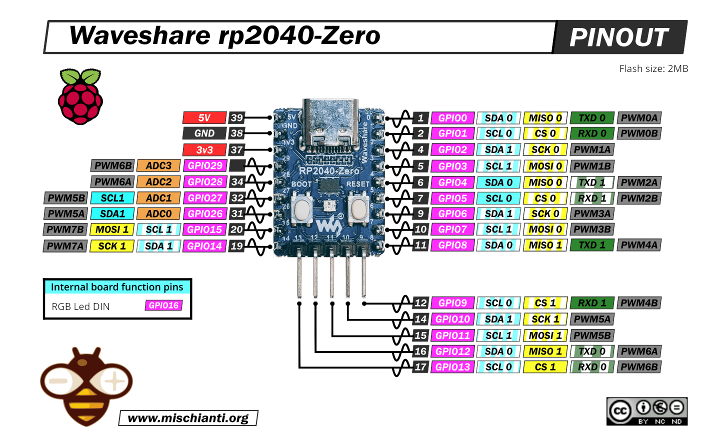 twin hedge
How do I include a drill in my PCB file? I'm using KiCAD.
supple pollen
I'm not sure what a PCM file is, normally the various board and milling layers are described with Gerber files, and the drilling is described with an Excelon file.
rancid lagoon
I’m pretty sure there are footprints for drills (like tht pads but no copper)
long wraith
I think for KiCAD you can just make holes in the edges layer? Was gonna try that later
twin hedge
supple pollen
I'm not sure what a PCM file is, normally the various board and milling layers a...
I meant PCB. My bad.
What do I need drills for? And what are drills?
long wraith
JLCPCB will detect holes for pins automatically
Or at least I think it does? I didn’t create a “drills” file for my upload
(But that was a test I haven’t had produced)
 silver marsh
twin hedge
How do I include a drill in my PCB file? I'm using KiCAD.
silver marsh
twin hedge
How do I include a drill in my PCB file? I'm using KiCAD.
There are “mechanical” holes in the default footprint library, if that’s what you need.
 velvet patio
distant raven
The buck they use is like a $2 IC for a single, they get it for like.. $0.60-$0....
velvet patio
distant raven
The buck they use is like a $2 IC for a single, they get it for like.. $0.60-$0....
I was surprised they were holding the price relatively low still using that part too. None of the pico "clones" can be powered off of a pair of nimh cells.
twin hedge
silver marsh
There are “mechanical” holes in the default footprint library, if that’s what yo...
I figured it out. Now my parts are being made and ordered. Thanks.
spice zenith
supple pollen
It sounds like a layer problem: OSHPark (and the other PCB houses) have specifi...
It turns out it was the color scheme they're using. The traces are there, but with that very dark purple overlay, they're the next best thing to invisible. I took some time with KiCad and fattened up the traces and have it looking like this now:

I also switched from the tssop package to the 3/10" dips that I can get on Adafruit because I know I can solder them myself. $3.80 for a set of three, order will be going in asap.
I also have the mounting holes so they line up exactly with a Feather, so it'll attach easily. Yeah, I know, it's not much of anything by comparison with some of the other designs I've seen in here, but for a first run at this I like it. 🙂
supple pollen
I would suggest connecting the unused inputs to something, although I realize ASAP may well have been a while ago.
spice zenith
supple pollen
I would suggest connecting the unused inputs to something, although I realize AS...
I'm an OLD school 74 series guy. As in messing with it back in the early 1970s when I was still a kid in school. Back in the good old days, you could guarantee that unused inputs would consider themselves to be high. Mind you, that was in the days of the "Multi-emitter-transistor" input circuitry. I have no clue at all what the actual silicon is inside one of these modern chips. I've got the ground line running conveniently up the middle of the chip pad, it'd be a no-brainer to tie 1,2,4,5 and 9 to it, which are the only floating inputs right now.
And for what it's worth, ASAP had already happened by the time you posted. 😉
Worst case, I can trot out my point to point wiring pencil. Best thing I ever bought. It's a thing like a pen with a small spool of really fine "solder through" insulated wire on the back end, and it just threads through. Tack it to one pin, run over to another, tack it to that, boom, instant jumper wire.
rustic linden
nice!
long wraith
I have seen those
I thought any chip that was the same part number was always the same internally — like, isn’t a 555 now the same as a 555 from decades ago?
spice zenith
long wraith
I thought any chip that was the same part number was always the same internally ...
You'd think so. But I've seen enough weirdness over the years to make me always want to check the datasheet. No matter what ...
long wraith
Fair
spice zenith
Anyway. Time for sleepy-byes for me. Case for the holiday lights v2 has printed, it now need to chill out (both literally and metaphorically) in the freezer for a while so I can get it off the baseplate.
My wife gave me a hard time about the mess of boxes and wires tie-wrapped to the bottom of the tree this year, claiming it looked like a "Boris and Natasha" job from Rocky and Bullwinkle. It was a bit of a mess, I admit, but we were able to cover it up by wrapping tinsel around it. Should be much neater next time. 🙂
long wraith
Lol. Nini
@distant raven hey, where did you start when you decided to make your own RP2040 board?
distant raven
long wraith
<@728676724522352733> hey, where did you start when you decided to make your own...
long wraith
Ah, yeah, forgot that existed
distant raven
I also referenced Adafruit’s boards
distant raven
long wraith
Is there a way to convert EAGLE files to KiCAD?
You should be able to directly import them
 rain remnant
i head altium also offer some free trial or something
long wraith
distant raven
You should be able to directly import them
Oh, cool
distant raven
rain remnant
i head altium also offer some free trial or something
7 whole days last I looked
Oh it’s 30 days
 bitter flare
I had an idea to re-use the Beaglebone footprint and pin headers as a microcontroller platform for ESP32/Teensy/whatever: https://agroecologylab.org.uk/open-hardware-electronics/ is there any merit in the idea, or should I think of something else.
supple pollen
Re-using footprints is an old and respected idea, why re-invent the wheel?
long wraith
why RPi has maintained the same base GPIO pinout
bitter flare
supple pollen
Re-using footprints is an old and respected idea, why re-invent the wheel?
Do you look at any of the concept boards and think, 'I might actually use that' ?
supple pollen
Concept boards?
bitter flare
long wraith
Is there a way to convert EAGLE files to KiCAD?
Just: 'Import > Non Kicad file' in the Kicad menu.
bitter flare
supple pollen
Concept boards?


Featherwing / CM4 / Micromod (ESP32/Teensy/ RP2040 etc) / UEXT
CM4 obviously not Microcontroller, but it seems like an obvious one to do..
latent grotto
How do I create a vscore on fritzing? Ive looked it up and cant find anything useful on it
 eternal fox
Does anyone know of a USB switch where you can have one keyboard switch between 2 or more computers/devices through the press of a button (and a connected cable obviously)? Would love to incorporate something like that in a stealth build im making for my job keyboard 🙂
Could you not make a board that had 4 usb inputs and one out to a usb-hub, connect the four inputs to different hosts and use a 4 position switch to cut power and data to each input but the current chosen input? I guess that if it was that easy there would be way more switches to choose from right.
supple pollen
It seems like there ought to be a KVM switch that could do that. They're popular in data centers where a shared keyboard/monitor is used on many machines in racks.
 sick geyser
Yeah just for USB they definitely exist too https://www.pbtech.co.nz/product/MPPUGR30768/UGREEN-30768-2-In-4-Out-USB-30-Sharing-Switch-Box

PB Tech
pbtech.co.nz "UGREEN 30768 2 In 4 Out USB 3.0 Sharing Switch Box
eternal fox
Yeah its basically a KVM switch but without the video part of it. What would you expect to see in such a switch and is it possible to "just" turn off one host port and turn on another host? Or do you have to start doing some fancy disconnection before you start cutting data and power between hosts and devices?
The problem is as usual the formfactor of what i want to achive and that forces me to create what i need rather than to buy ready made products. You dont know of a good guide on how to make something like this work? 🙂
supple pollen
I'm unsure how much you have to do to keep USB happy and not generate disconnect/reconnect events. For a keyboard alone (or even a keyboard and mouse), I might just use a pair of USB capable microcontrollers emulating keyboards, and just have the selected one send the keystrokes.
eternal fox
That certainly sounds like a way to do it... I guess that would solve any power issues as well that would come from switching hosts and probably wouldnt screw with the host side controller, right?
rustic linden
that should work
rustic linden
it it would work with like, a feather, it should work with your
woven bluff
is 0.2/0.4 a reasonable via size for small signal (e.g. enable pin)?
because I need vias that can be placed between, or beside pads
 violet portal
good afternoon all! I decided today would be a great day to dive under the hood of pull-up's and pull-down's as in my experience the topic of Pull-Up's is well covered, but pull-down's essentially get "these work the same as pull-up's" which I find to not be the case
this from sparkfun: https://learn.sparkfun.com/tutorials/pull-up-resistors/all is a pretty good example and is one of the few to refer to what's inside the device you are connecting a pull-up/down to

it is not a simple resistor, but the concept that a high-impedance path from the input pin to ground exists forming a voltage divider with R1 is quite intuitive and useful and provides an easy explanation
however on pull-down, i find little to no dives; the article above offers only
For simplicity, we will focus on pull-ups since they are more common than pull-downs. They operate using the same concepts, except the pull-up resistor is connected to the high voltage (this is usually 3.3V or 5V and is often refereed to as VCC) and the pull-down resistor is connected to ground.
and indeed the top google results for "pull-down resistor" offer the same
- https://www.electronics-tutorials.ws/logic/pull-up-resistor.html
- https://eepower.com/resistor-guide/resistor-applications/pull-up-resistor-pull-down-resistor/
- https://www.circuitbasics.com/pull-up-and-pull-down-resistors/
- https://circuitdigest.com/tutorial/pull-up-and-pull-down-resistor
- even wiki offers nothing!: https://en.wikipedia.org/wiki/Pull-up_resistor
the most common explanation (when the switch with a pull-down is open) is "when the switch is open, no current flows, so no voltage drop across the pull-down resistor means the voltage at the input pin is 0" and for some reason my gut is saying that's essentially true, but not completely... (it's certainly the logic i've used for many years though!)
this paper from TI: https://www.ti.com/lit/an/slva485/slva485.pdf refers to leakage current from a controlling IC summing with leakage current from a uC's reset pin to create a small voltage drop across the pull-down, and so the actual voltage is slightly higher than ground
supple pollen
woven bluff
is 0.2/0.4 a reasonable via size for small signal (e.g. enable pin)?
Details like that depend on your board house. They'll usually have a capabilities page where they describe the trace/drill/clearance sizes they support, and which will result in additional charges.
violet portal

this post: https://electronics.stackexchange.com/questions/617102/do-circuits-with-pull-up-resistors-waste-more-electricity-than-circuits-with-pul implies that due to the complimentary FETs on an input pin, you will get small leakage currents that cause a small voltage drop on the pull-down

Electrical Engineering Stack Exchange
A pull up resistor provides a constant voltage (and therefore some current) to an input pin on arduino.
https://learn.sparkfun.com/tutorials/pull-up-resistors/all
A pull down resistor connects an a...
supple pollen
Often, the chip manufacturers will specify pull-up and pull-down performance as a current (such as 75µA). You can then calculate the resulting voltage based on the impedances of whatever is connected to the pin. Granted, it's generally not a regulated current either, but it seems to be a more useful metric than assuming it behaves like a resistor.
Even this nice diagram is an oversimplification http://www.mosaic-industries.com/embedded-systems/_media/microcontroller-projects/raspberry-pi/raspberry-pi-circuit-gpio-input-pins.png
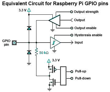
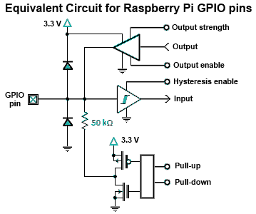 violet portal
cheers. its funny, to some degree im ok with over simplifications as long as they capture the spirit - so in that diagram you can see the complimentary pairs; I prefer texts that say "the internals are much more complex for a variety of reasons which are well worth diving into if that is of interest to you. However if you only care about building something cool with this device you can consider that no current flows through a pull-down when the switch is off - electrons will diffuse in the resistor such that no separation of charge exists and so no potential difference exists - in this state, a resistor appears as if it's just a length of wire" (for ages I conceptually understood that no current means no voltage drop; but for some reason a resistor acting as a wire just felt wrong!)
i don't like hand-waving that leaves more questions than answer 🙂
supple pollen
It's a tricky problem, as different people understand things in different ways. An explanation that works for most people doesn't work for everybody, but sometimes the "most people" one is the only one available (I am quite aware of this, as I'm not most people either)
violet portal
i just flicked through my copy of Art of Electronics; Pull Down's are not discussed at all!
woven bluff
is there any dedicated quadrature decoder IC, or they are generally handled by MCU?
unreal flax
woven bluff
is there any dedicated quadrature decoder IC, or they are generally handled by M...
Often an MCU's timer peripheral would be able to handle that directly, yeah, so there's not much call for a dedicated IC for it. There may be some older counter chips that can do it, though.
woven bluff
unreal flax
Often an MCU's timer peripheral would be able to handle that directly, yeah, so ...
mine is tricky, because I need 32bit, Arduino due does the job, but since not all pins are exposed, I'm forced to write counts on multiple ports .
spice turtle
I used interrupt on change pins to do it. Worked out pretty well. Basically detected when there was a falling or rising Signal and checked the state of the other pin to determine which direction it was going
supple pollen
woven bluff
is there any dedicated quadrature decoder IC, or they are generally handled by M...
ICs like that do exist (they're used in the sort of encoders that are in computer mice), but PJRC has a really nice library for it.
latent grotto
Does anyone know the process of reflowing a pcb board with pads on both the top and bottom
Ive been doing some research into it, and found that a reflow oven might work. But kind of scared that the bottom components will fall off.
blissful frigate
latent grotto
Ive been doing some research into it, and found that a reflow oven might work. B...
If the components are not unusually heavy they won't fall off. I've done numerous boards in an reflow oven that had smd components on both sides
dry pelican
latent grotto
Does anyone know the process of reflowing a pcb board with pads on both the top ...
what is your board?
although I think professionally they just reflow one side and then reflow the other side
solder may hold all the components in?
latent grotto
dry pelican
what is your board?
Its a custom one I have been working on for about a month
dry pelican
design screenshot?
latent grotto
Its a mess right now. I havnt even found a spot for some of the components. The slightly faded components are on the bottem layer
 distant raven
latent grotto
Its a mess right now. I havnt even found a spot for some of the components. The ...
distant raven
latent grotto
Its a mess right now. I havnt even found a spot for some of the components. The ...
Looks like a lot of space to me lol
All jokes aside, you can definitely shift things around to get them squeezed in
latent grotto
distant raven
Looks like a lot of space to me lol
Yeah there is a lot of space. I just didnt place stuff in the right spots lol
Its like putting a brick in a wall vertically then having to build around it lmao
distant raven
I spend a bit of time considering critical traces between components and place around that
latent grotto
Thats probably a good idea, I am still new to the pcb thing. Ive made a few simple ones for practice before I started work on this one.
distant raven
Funny enough, I don’t consider power/gnd critical because I can meander those around other traces
latent grotto
Would you consider stuff like i2c lines critical
distant raven
Yeah, any “high speed” signal you should try and keep to one layer with minimal layer hopping
dry pelican
If you're reflowing with a stencil, you can pack components as close as you want kind of.
I've never done it tho
latent grotto
The trace widths would have to be very small then
distant raven
latent grotto
The trace widths would have to be very small then
Not always, but generally I end up using 6mil,8mil, and 10mil for signal traces
supple pollen
I don't consider I2C "high speed", but it is sensitive to capacitance and interference
distant raven
supple pollen
I don't consider I2C "high speed", but it is sensitive to capacitance and interf...
I used air quotes for that reason lol
I2C can get up to 3.4Mbps though so definitely some considerations if you’re using devices that utilize it at those speeds
Most is only 400kHz though
long wraith
nyoom
dry pelican
Spi goes to 10MHz
And a parallel interface will go pretty much as fast as you want it to
distant raven
dry pelican
And a parallel interface will go pretty much as fast as you want it to
As fast as your host/peripheral will allow really
But you could definitely see a 2-3x speed boost over SPI
 fiery parcel
Hi folks, I'm trying to place a FeatherRP2040 on this board, sorta like I would do in Fritzing, though I have no idea how to do it. Would anyone know?
 woven bluff
is there a TFT that do not exceed the size of RPi?
woven bluff
preferably do not hijack all the GPIO strip as well.
woven bluff
this is a bad example, it terminated all GPIOs
what trace and pad clearance do you usually use?
supple pollen
fiery parcel
Hi folks, I'm trying to place a FeatherRP2040 on this board, sorta like I would ...
Do you mean you want to add a Feather as a daughterboard (Crickit style), in which case you just need to add two rows of pads, or do you want to re-implement the FeatherRP2040 circuitry on that board, in which case you would presumably import the existing Feather design and replace the board outline?
fiery parcel
supple pollen
Do you mean you want to add a Feather as a daughterboard (Crickit style), in whi...
Yes, I'd just need to add the daughter board
supple pollen
All you need in that case is the two rows of pads and maybe a silkscreen outline and possibly mounting holes
 vapid lark
https://cdn.discordapp.com/attachments/637812536158453780/1064980232970448967/image.png
Picture 1
This is the top of the board so my idea here (cause im out of any other and realy was the only way for me atleast) i would connect a power source on PWR-IN (say a 5V 20A) these screw terminals are rated for 20A not that i would use 20A!! and as you can see there will be power going from the in to the ESP32 on the PCB board it self.

https://cdn.discordapp.com/attachments/637812536158453780/1064980233226309642/image.png
Picture 2
then on the bottom i would solder thick wires between the 2 screw terminals to handle atleast 10A or more

Question
is this stupid? is there a better way? or would this be safe / fine todo?

 supple pollen
In commercial gear, I'll see a wide PCB trace with no soldermask, then they'll either layer solder on it to give it more carrying capacity, or overlay it with a wire or wires for even more.
vapid lark
supple pollen
In commercial gear, I'll see a wide PCB trace with no soldermask, then they'll e...
so still use traces between the two and just solder on it ?
supple pollen
That's what I'd do, but not using traces avoids trouble if you forget to add the wires, what makes the most sense depends on your preferences
vapid lark
5mm traces ok? :S i dunno how thick the traces should be