#help-with-hw-design
1 messages · Page 9 of 1
 fervent lance
 knotty tiger
i think the usual approaches for suppressing cloning in this area involve trademark law, and they're expensive to implement well
 supple pollen
I'm wondering if the question is "which license permits re-use but not making a closed-source derivative" more than "how do I enforce a license"
knotty tiger
yeah, i'm not familiar with a copyleft open-source hardware license offhand, but there's probably room for one if there isn't already one
 regal lodge
then don't open source it
even OSHWA says it: if you can't handle that happening, don't release it as open source hardware
no license can protect hardware
knotty tiger
also, even copyleft won't help you if they clone it without changing it
regal lodge
hardware is covered by patent law, patents are not implied
you get a patent by forking over $50k to the government/a lawyer
you cannot protect hardware with a copyright license because hardware is considered functional, so it's covered under patent law
supple pollen
I think cloning is intended to be allowed, just not copying the work into a closed-source project
regal lodge
you can protect the software side of it with copyright
in that case, GPL
or CC-NC
but no copyright license can protect hardware
the only legal thing stopping you from opening up your phone, nintendo switch, etc, and reverse engineering the entire thing is patent law
supple pollen
I'd argue that the DMCA does as well (not that I like or support the DMCA, but I do recognize that it exists)
regal lodge
it does and it doesn't
to get access to the IP contained on the games and such? yes it does stop you
to clone the hardware? it does not
knotty tiger
@broken zenith what exactly are you wanting to prevent? other people profiting from your design? other people making derivatives of your design?
supple pollen
As they said originally, "I want something permissive, but not so permissive that someone can run off with my design, close source it, and sell it as their own."
regal lodge
I suggest you read this, it deals with 3D printer files but the underlying principle applies to PCBs as well (files that are intended to be used to make physical objects) https://publicknowledge.org/policy/3-steps-for-licensing-your-3d-printed-stuff/

The expiration of patents, as well as a worldwide effort to engineer open, low-cost desktop 3D printers, has begun to fundamentally alter an industry that had been flying under the radar for decades. However, as 3D printers become more accessible to more people, questions of ownership and control of 3D printed objects begin to arise more often. ...
my take has always been use a permissive license like BSD or MIT
because most people will at least follow the license then, even if they don't legally have to
 lean oriole
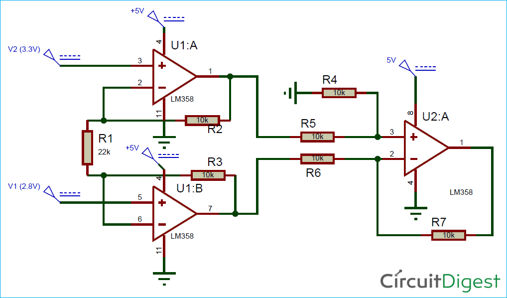
Oh sorry, here's a picture https://circuitdigest.com/sites/default/files/circuitdiagram/Circuit-Diagram-for-Instrumentation-Amplifier-Circuit-using-Op-Amp.png the six 2k resistors go where the 10k ones are and the 20 ohm resistor goes where the 22k resistor is.
The formula that I got to calculate power draw came from this stackexchange post https://electronics.stackexchange.com/questions/173731/choose-the-better-values-in-terms-of-range-for-resistors-in-this-non-inverting
The biggest obvious consideration is the current that the two resistors draw from the output. At 15 V out, the 2kΩ/1kΩ combination presents a load of 3 kΩ and will draw (15 V)/(3 kΩ) = 5 mA. The 2MΩ/1MΩ combination will likewise only draw 5 µA.
So if it's being fed 5v and it's using 2k and 20 ohm resistors, so adding that gives 2.020, then putting that into that formula gives 5/2.020 = 2.475 ma draw?

Electrical Engineering Stack Exchange
These days I'm looking at operational amplifiers; from what I've seen, implementing them in a circuit is quite simple, at least when they are connected as "non-inverting". Determining the gain/
 broken zenith
Thanks for the input on the licensing situation. I had no idea it was so nuanced. I guess I'll use the MIT license and hope for the best. I'd rather have made the design accessible to the masses through clones than have it be closed-source and not widely available.
¯_(ツ)_/¯
Thanks again for the advice!
fervent lance
broken zenith
Thanks for the input on the licensing situation. I had no idea it was so nuanced...
also quick note, if you're thinking to use amazon/ebay/etsy or similar platforms to sell your item, be aware that they are known to clone your product (either the platform itself or some third party sellers) and then ban you over the pretext that your product is a clone of theirs
fervent lance
That sounds overarching to me. Show your source on that, please.
 distant raven
fervent lance
That sounds overarching to me. Show your source on that, please.
distant raven
fervent lance
That sounds overarching to me. Show your source on that, please.
I’ve read a few articles about people selling white label products and not taking the proper steps to get trademarks and whatnot, someone coming in selling the same product and getting some legal status for the products they’re selling, then report the original seller for infringing on their business and copying
fervent lance
it's one thing for individuals to do that; a whole other to say Amazon, Etsy and eBay are all doing this as corporate regular practice. Which is .. just off the hook for an accusation.
That story'd make the New York Times. ;)
distant raven
Have you heard if Amazon Basics?
fervent lance
heha basica I like it. Yes I have a shower curtain they vended by that branding.
distant raven
They’ve put third party sellers out of business offering similar but immensely cheaper versions of product
Happens a lot
fervent lance
that's not the same thing at all or even close. come on. ;)
distant raven
It’s like when apple recreates a popular third party app and effectively shuts down the third party developer
If they are identical white label products it is
It’s leveraging their size to squeeze more dollars and put third party competitors out of business
fervent lance
Nah somehow you've walked it step by step into a fiction.
distant raven
Nah, there are plenty of articles about it

TechCrunch
Of all of the WWDC announcements this week, Sidecar got me the most excited. I’m on the road a lot these days, and apps like Duet and Luna have been lifesavers. They’ve afforded me the ability to carry around a reasonably sized laptop, with an optional second screen in the form of the iPad. Both […]
Example of Apple doing this
There ya go
Not fiction
There’s another example
Anyway, I’m stopping there so this doesn’t go too far off topic
fervent lance
Yeah I know i just didn't know what this would bring up or I wouldn'ta started it. ;)
(counting on a slam dunk)
 broken python
This is more a philosophical/practical question than an implementation question, BUT - I have a small project that I am debating custom PCBs for. I've never used any PCB software. What I want, is currently being achieved via a solderable breadboard with some Cat6 wires soldered as jumpers between the different points on the breadboard.
Is it worth it to spend the time and money making custom PCBs if the only thing I really "need" them for is added reliability/reduced failure points? Or is it better to just build a few more of what I've already done?
Also..... is there a webUI software or similar where I can design a "solderable breadboard" PCB where it's just a solderable breadboard, with a few of the traces connected to each other as I specify, without having to do the entire PCB specs?
supple pollen
Boards are amazingly affordable these days, but you're right, there is effort in learning the tools. You can use a tool like Fritzing to go from breadboard to custom PCB without learning an entire board design package.
distant raven
And 6+ layer boards are getting cheaper too
JLCPCB for instance automatically caps via in pad now
broken python
I only need 1 or 2 layer... very basic.
 worldly schooner
broken python
This is more a philosophical/practical question than an implementation question,...
worldly schooner
broken python
This is more a philosophical/practical question than an implementation question,...
The biggest question here is how many you need, as the main deciding factor is the cost of assembling these boards by hand? Your time and labor is worth something, after all.
Other advantages include form fit and aesthetic, which are also almost as valid a reason as function.
broken python
worldly schooner
The biggest question here is how many you need, as the main deciding factor is t...
I will be populating by hand, but it's much easier to lay everything out in through-hole fashion and just solder than it is to hold/bend/trim wire. And, the wire is not as reliable since it can be bumped and shear off, unlike a trace in a PCB.
I will probably order 10-20 of them, and that should hold me off for a couple years, as that will include spares.
 limpid nest
Does anyone have a favorite USBC port part number that is easy to solder?
distant raven
USB C and easy to solder usually don't go together... but any GCT brand USB-C connectors have been good to me
 long wraith
You can get ones that are breakouts if you have room and aren’t doing a custom PCB
limpid nest
I just need power, ground, d+/-
supple pollen
Note that USB-C has multiple data pins
 dry pelican
Another tesla coil-related development issue. I've gotten it to run reliably off of a 1.27MHz signal from my hantek function gen, but I can't get the circuit to self-tune from antenna feedback. I have a few possible solutions to test though: use a differnt form of feedback like secondary current transformer feedback, use a "buzzer" (fixed oscillator that is loosely capacitively coupled to the antenna to kick start the driver) like in Steve Ward's mini class E sstc, or removing the 100nF capacitor on the input of the feedback network. Does anyone have any other recommendations?
Current setup

With the antenna feedback instead of the fixed oscillator
supple pollen
Tesla coil? Radio shack soldering iron? Traxxas remote? Clip leads everywhere? It's like looking in a mirror!
dry pelican
Closer up of the board with capacitor to remove or short pointed to
 limpid nest
supple pollen
Note that USB-C has multiple data pins
limpid nest
supple pollen
Note that USB-C has multiple data pins
Yeah I was thinking about that
dry pelican
distant raven
JLCPCB for instance automatically caps via in pad now
Jlc does via in pad now?
distant raven
dry pelican
Jlc does via in pad now?
For 4L+ boards
 ember laurel
distant raven
For 4L+ boards
ember laurel
distant raven
For 4L+ boards
Nice I didn’t know
regal lodge
if I have a double sided board for power distribution and make one side + and the other side -, how do I calculate the safe current handling limit? all the tools I see seem to be focusing on trace width
would the trace width just be the shortest plane dimension?
knotty tiger
how contiguous are those power planes, really, if you only have two layers? what else is on the board?
regal lodge
nothing, it's literally just power
and the connectors

my friend wanted a distro board for his LEDs

all wired in parallel

the middle top plane is +12V, the entire bottom and outside edge of the top plane are GND
the middle top plane top to bottom is 53mm
the longest connection (top left to bottom right) is 125mm
knotty tiger
i think your limiting resistances will be the solder joints, component pins, and thermal spokes, not the power planes themselves
 supple sky
Does anyone know if these buttons are loose? I have another set like this that kind of rotate around the middle of the button so it makes the square toppers look off when they're next to each other.

Adafruit Colorful Square Tactile Button Switch Assortment - 15 Pack [ADA1010]
Seems like a terrible explanation, lol.
long wraith
Trying to open a BigClive project, want to make some tweaks... any ideas what opens these files [and why there are different file types for apparently different layers?]

 unreal flax
I'd expect that they're the same Gerber file format, just named with different extensions.
You can open them in a Gerber viewer.
Note that these are the equivalent of printing out a file, so generally you would not edit them to make changes to the board... that would be done upstream with the PCB design files.
 woven bluff
is ADS against the rules?
long wraith
ADS?
woven bluff
active denial system
long wraith
Hmm... non-lethal... but "weapon"... I'd see what a mod says when one shows up
woven bluff
you can also weaponize tesla coils
long wraith
True, but they're not a weapon by default... So yeah, I'd wait for a mod decision before getting into ADS
 merry grail
I'm having issues with ws2812's. I've had 3 burn out on my custom pcb now. One of them will start flickering (that flickering is passed down the chain) then it will eventually burn out completely. After reading a bit I did install a small resistor at the beginning of the data line. However I failed to give each LED a capacitor.
The board is USB powered and is getting 4.6v.
distant raven
I suspect something else going on than the capacitors not being there
supple pollen
That's a weird one. I'm guessing it's either a power problem, or a batch of flaky LEDs. Capacitors may help for certain kinds of power problems, but not for others.
distant raven
It almost sounds like the power supply isn’t consistent
merry grail
It's a keyboard I have connecting to my computer through a usb hub...
supple pollen
USB power is 5V, so I'm curious why it's 4.6V. Is there a dropping diode or regulator? How are you measuring it?
I guess if it's an unpowered USB hub, it could have some voltage drop of its own.
merry grail
I measured it right at the jack because I'm not regulating the power going to the leds.
supple pollen
Measured it with what? A multimeter? If so, there could be high frequency noise on the power line confusing the reading. What do you get if you measure it on an AC scale?
merry grail
Multimeter. I'll try...
When I turn the meter to AC and measure it reads .04v. Is that what you mean by measure it on an AC scale?
supple pollen
Yes. 0.04V isn't much, which implies there isn't much high frequency noise on the power.
merry grail
Sweet, clever trick!
distant raven
Are you level shifting the data line by chance?
For the leds that is
And what are you using as the brains of the keyboard?
merry grail
I'm not level shifting. Could that cause burn outs? rp2040 on a 3.3 reg.
The data sheet says +-.7v. I may have miss read that before.
distant raven
Yeah, ws2812 are more sensitive to the data line not being the same as supply
You’ll need to level shift the data, you can use a BSS138 to level shift it to your input voltage
merry grail
Sweet! Thanks for the help.
knotty tiger
i think it’s theoretically possible that a logic input that’s in the invalid region for too long can cause large current flows that eventually destroy the device. like 3.3V logic to a 5V NeoPixel might do it, depending on the specific chip and lot
distant raven
knotty tiger
i think it’s theoretically possible that a logic input that’s in the invalid reg...
Yeah definitely. This is why I like the SK6812 instead because they have a built in constant current driver which means 3.3V on the data lines is perfectly fine
fervent lance
You like it because it's sk-anything ;) /just_kidding
Sam Wsabi likes the other kind. ;)
distant raven
One design that no matter how I try it I can’t get it right is the ESP32-S2 bare chip. I can use the modules just fine, but anything I do bare chip just doesn’t work. 40MHz crystal doesn’t oscillate at all despite the all the pins having good electrical connection when inspecting under a microscope
It might be one design I give up trying to use anything but the modules
 rancid lagoon
You sure it isn’t bad chips?
distant raven
That’s a lot of bad chips, 10 from different orders on different designs
 unique patio
distant raven
One design that no matter how I try it I can’t get it right is the ESP32-S2 bare...
unique patio
distant raven
One design that no matter how I try it I can’t get it right is the ESP32-S2 bare...
did you compare your design with, say, the QT Py ESP32-S2?
distant raven
unique patio
did you compare your design with, say, the QT Py ESP32-S2?
I did, and that's where i'm lost.
unique patio
I have no particular suggestions besides that
distant raven
yeah, it makes no particular sense to my why it doesn't work. i've followed the hardware design guide and checked based on the QtPY ESP32-S2
rancid lagoon
distant raven
That’s a lot of bad chips, 10 from different orders on different designs
just going through the basics
distant raven
I understand, I thought that on the first that didn’t work, but so many failures.. I’m not sure if I’ll pursue it outside of using the module anymore
I’m gonna try the C3 one of these days though, raw chip
 green wadi
Using the BQ chargers from TI (and probably with most other lipo-charging IC's) you can set the charge-current using a resistance to ground. Would it be an issue if you had to place 10 of those IC's on a board, and they'd share the same resistor network?
supple pollen
I suppose it depends on how that resistor is used. I suspect in some chips it's connected to a current source and the voltage across the resistor is used as a comparison to the voltage developed across a current sensing resistor. If so, ganging up a bunch of ICs would multiply the current through the resistor. If so, you might be able to scale the resistor by the number of ICs and they'd then all use the aggregate voltage. The data sheets on the particular ICs in question should give more information on how the current setting resistor is used, which might shed light on how practical it would be to use a shared one.
green wadi
That makes sense. I'll dive into the datasheet a bit further. Thanks!
distant raven
green wadi
Using the BQ chargers from TI (and probably with most other lipo-charging IC's) ...
Which BQ charger IC?
green wadi
Currently looking at the BQ25170.
I feel like it is acting as a current source as I can see this paragraph:
For charge currents below 50 mA, an extra RC circuit is recommended on ISET to achieve more stable current signal. For greater accuracy at lower currents, part of the current-sensing FET is disabled to give better resolution.
distant raven
Just looking at the data sheet, you likely want to have the resistors for each IC
Mostly because of the internal circuitry and how other ICs could influence the others.

This bit in particular
There’s not likely a breakdown of how that Pin Detect and ref DAC works internally
green wadi
Right. And a possible way it would work would be to put various voltages on the pin I guess?
supple pollen
TI operates a forum where you can ask questions like that if the information isn't available from the data sheets or application notes.
distant raven
Yeah
That would be the best place to get specific information, but I’d suspect they’d tell you each chip should have its own components
Definitely report back though, I’m curious now
green wadi
I will! Thanks for the info guys
 split obsidian
I'm interested in making a design similar to the adafruit Macropad. The product page states that it has an amplifier of some sort attached to the 8mm speaker? Can anyone speak to the model of that amplifier circuit or that segment of the circuit in general? I don't see a schematic but would really appreciate some insight into the design decisions there.
Additionally, if I was considering i2s for my design, can I just tie word select to low or high to save a pin if I want it to be mono-output??
limpid nest
Have you looked at the schematic?
split obsidian
I was unable to find the schematic. Is it available?
limpid nest
One sec
split obsidian
oh goodness
I just needed to google adafruit macropad schematic lol
I was looking on the product page and assumed it wasn't there
limpid nest

Adafruit Learning System
Twelve buttons, an OLED, and rotary encoder - it's the MacroPad RP2040!
Yeah love how adafruit gives all their deets like that. It's usually in the Downloads section of a relevant guide
 pure gorge
Anyone know how vias and through-holes are plated on a PCB? I'm looking for an easy way to plate a via on a DIY PCB. Looks like some more industrial methods melt copper into the hole, but I can't really do that.
knotty tiger
pure gorge
Anyone know how vias and through-holes are plated on a PCB? I'm looking for an e...
it's a rather complicated electroplating process, last i checked. like it requires bizarre electrical waveforms; DC isn't good enough. most DIY PCBs that need through-holes connecting two sides will use something rivet-like (sometimes sold in kits)
pure gorge
Interesting, I've never seen a rivet in a board to act as a via. I'll look into that, thanks!
fervent lance
You can just drill a hole and pass a wire through. ;)
knotty tiger
are you wanting to do this for learning purposes, or is this a product or prototype that needs to be reliable?
pure gorge
I'm just experimenting with it so I can prototype PCBs before I go and order them
knotty tiger
my understanding is that your average small-job PCB fab will probably produce plated through-holes and vias much more reliable than you could DIY
distant raven
pure gorge
I'm just experimenting with it so I can prototype PCBs before I go and order the...

Thinking to manufacture PCB at home? You may want to know how to put copper inside of a VIA.
Watch the full interview here:
- How Does Copper Get Inside of a VIA Hole in Your PCB - Do you know this? https://youtu.be/ukfsupePkOM
Would you like to support me? It's simple:
- Sign up for my H...
If your interested in the process
I watched this a year ago and it was very informative
fervent lance
YT uses digraphs?
distant raven
Probably
fervent lance
katzenjammer kids!
oh youtu dot be oops my bad - I don't use that enough to have it tracked for spelling; youtube.com I know on sight and I've never seen a digraph in those URIs iirc.
 spice turtle
Is there anything I should be aware of if I use a differential amplifier with a fractional gain (so 0.5)? I basically want it to do what it does (subtract) but also scale the signal down. Im thinking that using a fractional gain is the best way to do it, rather than use a voltage divider on the output.
supple pollen
Some amplifiers can be unstable with a gain of 1 or less
woven bluff

will this enable pin work to turn on/off the boost regulator?
Float->on High->on Low->off
spice turtle
supple pollen
Some amplifiers can be unstable with a gain of 1 or less
what spec should I look out for that will tell me that?
fervent lance
just use an attenuator I'd think - some are essentially calibrated in dBm.
spice turtle
So go with using a diff amp at G=1 and use a VDR?
woven bluff
boost regulator is enable/disabled by the voltage supervisor, and Q1 overrides the voltage supervisor to force disable boost regulator
fervent lance
supple pollen
woven bluff
will this enable pin work to turn on/off the boost regulator?
You have several things labeled, and the EN signal circled isn't connected to the boost regulator?
spice turtle
supple pollen
<https://e2e.ti.com/support/amplifiers-group/amplifiers/f/amplifiers-forum/79150...
Reading now, thanks
And I remember I had issues with op-amps wanting to oscillate at G=1 as well. I had to put a small capacitor in the negative feedback loop. I forgot the technical term though.
woven bluff
supple pollen
You have several things labeled, and the EN signal circled isn't connected to th...
no ,it's not, it's connected to the gate of Q1, because boost regulator has to be controlled by the voltage supervisor
spice turtle
also I found this too:
https://www.analog.com/en/analog-dialogue/raqs/raq-issue-56.html
knotty tiger
distant raven
https://youtu.be/2hvMgG6tKdg
thanks for the pointer! i watched the long version of that video, and it is very informative
ember laurel
So, we finally got FDA authorization for my dental motor drill system that I've been working on for the past 2 years. Thanks everyone for help and hints in this channel!
green wadi
distant raven
Definitely report back though, I’m curious now
Their answer was the following:
The ISET and VSET resistors should not be shared, each unit gets its own resistors. RC -circuit in not needed, if you are concerned with part count the benefit of the RC is limited.
https://e2e.ti.com/support/power-management-group/power-management/f/power-management-forum/1181492/bq25170-share-iset-and-vset-resistors-between-identical-ic-s/4450152#4450152
Part Number: BQ25170
Hi TI!
I'm developing a board that will have 10 x BQ25170's on it. To reduce the BOM, I'm wondering if I can share the resistor-networks
A rather dry answer, but I guess that sorts it. Thanks again for your suggestions!
limpid nest
ember laurel
So, we finally got FDA authorization for my dental motor drill system that I've ...
Hey congrats!!!
 scarlet jay
Hey Gs, need to connect these 3 parts 🙂

Can somebody help guide me through this? Ill help him/her 🙂
limpid nest
I think paid work is discouraged here. There's a method to get that, the adafruit jobs board, but odds are you'll get what you need for free
scarlet jay
Thank you, do you think we can sometimes jump on a videocall? I can maybe help you with my marketing skills if you desire? 🙂
 twilit mango
scarlet jay
Thank you, do you think we can sometimes jump on a videocall? I can maybe help y...
twilit mango
scarlet jay
Thank you, do you think we can sometimes jump on a videocall? I can maybe help y...
Hello. As OatsNHoney stated, we do discourage attempting to solicit paid work through our Discord server. We cannot moderate it, or have any control over how it goes, and therefore we cannot condone it. You can head over to https://jobs.adafruit.com and post there. However, in this case, as also stated, the community here is likely to help you without expecting pay. That's a huge part of what this server provides is assistance with projects like this. Further, please do not solicit video chats with community members who have not already offered to do so - again we have no control over video chat content, and unless it is agreed upon by both parties, we do not suggest it. So, please ask your question and be patient, as most of the folks here are community members volunteering their time around the rest of their life obligations. Thank you.
Find maker jobs in 3D and CAD, Art, Design, Education, Embedded Development, Engineering, Fabrication, Marketing and Communications, and Web Development
scarlet jay
@twilit mango thank you for stating that. I am highly thankful for your help. I am slowly helping other move forward in this segment as stated before so I canhelp in advance 🙂
spice turtle
scarlet jay
So what are you trying to accomplish? You are using a LM317 in constant current mode with a very small battery. It wont be enough to power much for any length of time unless you really cut down on things and put them into sleep.
woven bluff
is there some kind of PMIC that allow parallel charge and serial discharge of batteries?
long wraith
If you’re talking about LiPo, you can get a BMS (battery management system) board for that
woven bluff
I believe they are all made with chinese crap
long wraith
Most are made in China, but they’re not all crap
spice turtle
You can actually find the IC used on lcsc.
https://circuitdigest.com/electronic-circuits/lithium-ion-battery-management-and-protection-module-bms-teardown-schematics-parts-list-and-working
This article may be of help.
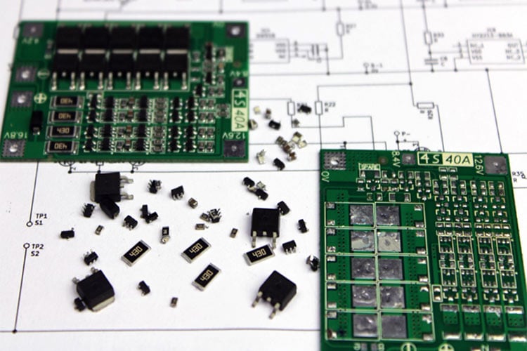
AFAIK, I havent found "single" balancer IC's made by TI, Microchip or Analog
distant raven
It’s mostly that it’s not really smart to try and do parallel charge with serial discharge. Lots of dangers involved. It’s better to use a battery pack that already does that, and can be charged by a multicell charger
And all the major brands make great multicell chargers that can balance charging loads

Just a quick screenshot of a few options for multichem that do 1-4 cells
spice turtle
I get why they want to do it-Ive had that thought before too. Its to avoid using a BMS or having to deal with balancing. But these days a balancer will be a few bucks or you can build your own.
I just wish all the balancers/gauges werent in ridiculous packages 😭
scarlet jay
spice turtle
So what are you trying to accomplish? You are using a LM317 in constant current ...
so, I want a power output that is controllable and a bluetooth earphones that are simoultaneously controllable
by a processor or controller 🙂
long wraith
spice turtle
I get why they want to do it-Ive had that thought before too. Its to avoid using...
I prefer the BMS route because then it’s a 2-wire power requirement instead of n*cell_count+GND
supple pollen
scarlet jay
so, I want a power output that is controllable and a bluetooth earphones that ar...
Oh, you want a current regulated supply you can vary the current programmably? Do you just need to switch between a couple of levels, or do you need finer control? What's the minimum current? What's the maximum current? What's the voltage compliance, or do you want to control voltage as well?
woven bluff
some power bank can be charged by 5V, but can deliver 65W with usb PD
how do they do that?
high current boost from 4.2V is not possible because gate won't open at this voltage for high power FETs
supple pollen
The usual approach is to build power controllers with internal boost circuits to provide higher gate drive voltage. Another approach is to use low current boost during charging, to charge a series pack, but that's rarely used.
And there are high power FETs available that can be controlled with low gate voltage.
woven bluff
at least SiCFET wont open
supple pollen
I normally see those kinds of parts in much higher voltage use (like the hundreds of volts in an electric vehicle).
woven bluff
they are just much better than MOSFET in every way except for gate threshold
also I haven't seen much GaN parts, but there are lots of commercial product already using it.
supple pollen
They do tend to have higher channel resistance and gate resistance, so not quite "much better in every way". Like all engineering, it's a bunch of tradeoffs.
woven bluff
do you know any fixed frequency SMPS controller that does not require any kind of compensation?
scarlet jay
supple pollen
Oh, you want a current regulated supply you can vary the current programmably? ...
Hey @supple pollen thank you many times. The thing I need is something to have 3 modes for now. Ill see how far it will go later. That means 3 different currents and 3 different audio waves.
spice turtle
Voltage mode SMPS's dont require compensation. Only current mode does. Theres quite a few with internal compensation though.
woven bluff
spice turtle
Voltage mode SMPS's dont require compensation. Only current mode does. Theres qu...
II have seen chips with internal slope compensation but never seen one with error amplifier compensation.
PFM oscillator does not need compensation, like max1771, but it's hard to keep the switching frequency out of hearing range
I want to make a portable CC/CV power supply capable of at least 50W output, powered by 4x18650 parallel
spice turtle
I built one but I used a PIC micro. It did what I needed to but I also didnt do any sort of compensation. It just worked.
I did do one with a TI part as well
woven bluff
spice turtle
I built one but I used a PIC micro. It did what I needed to but I also didnt do ...
a lot of people would say MCU SMPS is quite dangerous...
spice turtle
woven bluff
a lot of people would say MCU SMPS is quite dangerous...
Any particular reason? Its not offline.
woven bluff
MCU can hung, also it's hard to write code for fault situations
spice turtle
woven bluff
I want to make a portable CC/CV power supply capable of at least 50W output, pow...
also, I think EEblog did something like this.
https://www.eevblog.com/projects/usupply/
woven bluff
I want to step up the game and use synchronous rectifier + 2x SiCFET with SEPIC topology
woven bluff
spice turtle
also, I think EEblog did something like this.
https://www.eevblog.com/projects/...
wow, that's huge parts count, I'm not a fan of discrete parts when IC is available
spice turtle
I mean yea, you can get rid of some of the ICs, for example using a current sense amp in place of the two op-amps that are sensing and amplifying current. The rest you might need.
But you can pick off what you dont. If you dont need arduino you can just use a pot instead, get rid of the I2c, switches, encoders, ethernet, etc
woven bluff
spice turtle
I mean yea, you can get rid of some of the ICs, for example using a current sens...
a SMPS controller will replace most of the parts in PSU section
spice turtle
It looks overly complex but if you break down the components, its not bad. Its also a linear regulator too
woven bluff
spice turtle
I mean yea, you can get rid of some of the ICs, for example using a current sens...
https://www.maximintegrated.com/en/design/technical-documents/tutorials/8/818.html very nice article for digitally controlled SMPS
spice turtle
 woven bluff
I'll opt for DAC injection to feedback node for voltage control
spice turtle
This was a SMPS based CC/CV charger I made
woven bluff
I'll need high power, so integrated switch is not an option
woven bluff
basically, its SMPS+line regulator
power is the issue, I might need synchronous buck-boost to satisfy high current and high voltage range
also 4 FETs lined on a board looks badass 😎
spice turtle
Microchip has some too
Look into the dsPIC series
Theres a starter kit-I forgot about that.
dsPIC33C_Digital Power Starter Kit
woven bluff
PIC SMPS... humm too many components, it needs gate driver, bootstrap diode, another PIC, external compactors
and it's not even buck-boost
spice turtle
you have to roll your own. Its meant to be an example, not a end all do all. Its quite a complex project.
ahhh Im posting too quick
woven bluff
still, too many parts
and if the MCU hang, goes smoke
RP2040+LT8392 is far simpler
woven bluff
well, its Cortex-M, so yeah, MCU
woven bluff

are those stacks really necessary?
can I just use more expensive part with lower ESR?
what's the purpose of those ceramic stacks? they are not bulk cap or decouple cap
distant raven
the purpose is getting as close to the desired capacitance as possible
dry pelican
It is 96W of 98% efficient synchronous buck boost capacitor, so I would put them in. I'm guessing that the caps are to reduce ripple, decouple, and maybe increase efficiency, but I don't know for sure.
distant raven
you could probably use a 47uF ceramic, but it's not as close to the calculated values
woven bluff
distant raven
the purpose is getting as close to the desired capacitance as possible
is 40u and 47u that much difference? also 470u and 480u
dry pelican
But I don't know why stack them so much. Maybe to make tge design cheaper or something
distant raven
it can be a big difference.
knotty tiger
are the capacitor types specified in the app note/design? like ceramic vs electrolytic?
distant raven
especially given the frequency response at different capacitances could change ripple and other transient changes.
and could also reduce efficiency and output load.
woven bluff
most caps are +-20%
distant raven
right
dry pelican
woven bluff
RP2040+LT8392 is far simpler
How are you controlling the lt8392 with a RP2040? Digipot?
woven bluff
dry pelican
How are you controlling the lt8392 with a RP2040? Digipot?
DAC injection at FB node, also CTRL pin(max current) takes DAC input
dry pelican
woven bluff
DAC injection at FB node, also CTRL pin(max current) takes DAC input
?
Lt8392 looks like a good IC. 98% efficiency. Wow. That's crazy
dry pelican
woven bluff
DAC injection at FB node, also CTRL pin(max current) takes DAC input
So just hook up a dac to the FB input, monitor the output voltage, and program a "resistor divider" in the uC?
distant raven
'''. CIN and COUT loss. The input capacitor has the difficult job of filtering the large RMS input current to the
regulator in buck region. The output capacitor has the
difficult job of filtering the large RMS output current in
boost region. Both CIN and COUT are required to have
low ESR to minimize the AC I2R loss and sufficient
capacitance to prevent the RMS current from causing
additional upstream losses in fuses or batteries.'''
woven bluff
dry pelican
So just hook up a dac to the FB input, monitor the output voltage, and program a...
dry pelican
That might create a problem if the uC can't respond fast enough. But 133MHz is really fast (yes the actual response time will be much lower).
woven bluff
that reference design is just around 200KHz
woven bluff
distant raven
'''. CIN and COUT loss. The input capacitor has the difficult job of filtering t...
large capacitance = low esr, no?
dry pelican
Actually tge response speed problem would only be a problem with what I tgought you were doing. DAC injection is a much smarter method.
woven bluff
what if I just slap 0.01F cap on it
knotty tiger
woven bluff
large capacitance = low esr, no?
often not, especially with electrolytics
distant raven
I'd suspect that since capacitance appears to affect output, that deviating from the recommendations could affect things negatively

this is a 4A output rather than 8A
they use 2x 4.7uF
dry pelican
That's a lot of capacitor - 10000uF (10mF)
woven bluff
distant raven
I'd suspect that since capacitance appears to affect output, that deviating from...
that's bad, because my application is variable load and variable output voltage
distant raven
I'd chose something like a X7R 10uF, probably 0805 sized ceramic for those stacked ones on input
knotty tiger
too much capacitance can cause inrush current and startup problems
woven bluff
dry pelican
That's a lot of capacitor - 10000uF (10mF)
very common for coilgun 😎
distant raven
if you want variable voltage and load, probably want some kind of Flyback regulator
woven bluff
distant raven
if you want variable voltage and load, probably want some kind of Flyback regula...
transformer is nightmare
distant raven
there are flybacks that don't use transformers.
I've used one before, but it won't meet the requirements you have for voltage and load
dry pelican
distant raven
there are flybacks that don't use transformers.
How does that work? I thought flyback meant transformer with a diode.
distant raven
dry pelican
How does that work? I thought flyback meant transformer with a diode.
honestly, i'm not really sure. it was picked by someone else and I implemented it. it's been a while since i've looked at it.
anyway, going to drop off. this is getting beyond where I can provide useful insight. gotta go eat some dinner 🙂
good luck
woven bluff
I have this chinese module https://www.qskj.cc/shop/product/1941620-80w-dc-dc-converter-10-35v-to-1-35v-automatic-step-up-down-module-charger-qs-1212ccbd-80w-79147

Satistronix Group Limited
they sanded the inscribed text off the main IC
dry pelican
woven bluff
they sanded the inscribed text off the main IC
I hate that. There's no reason to on such a cheap non-patented product that has many clones.
woven bluff
that's normal practice for chinese crap
dry pelican
Yes
woven bluff
it only has one inductor, so it cannot be SEPIC. and two cheap FETs, so my guess is asynchronous buck-boost, but I cannot find the diodes
dry pelican
Sometimes you can't find the datasheet for those ICs even if you know the part number.
dry pelican
woven bluff
it only has one inductor, so it cannot be SEPIC. and two cheap FETs, so my guess...
One of those "fets" might be a diode. I've seen that before.
woven bluff
it has LM358, I guess that's for line regulation
dry pelican
Actually, I think that's for current limiting
There should be a shunt or shunt trace
woven bluff
dry pelican
One of those "fets" might be a diode. I've seen that before.
you are right!
one diode, one FET, one inductor...
how can it go up and down?
dry pelican
Inverting buck-boost?
woven bluff
I thought buck-boost need two FETs and two diodes
dry pelican
They're going to go with the cheapest thing. That might be it. The LM358 might also be something that gets the voltage from the output to the feedback since it has a different ground reference.
woven bluff
or 4 FETs for synchronous
woven bluff
dry pelican
Inverting buck-boost?
IN- and OUT- is not on the same net, but connected with a 10 mOhm resistor
dry pelican
That sounds like the current sensing shunt
How are you measuring such low resistance?
My multimeter would detect that as a short
woven bluff
it's has printing: R010
humm, I found its schematic

so its not a inductor...
a flyback afterall
I don't know why flyback is superior than 4 switch buck-boost in variable load and voltage operation
spice turtle
Isolation
woven bluff
spice turtle
Isolation
I don't need isolation, also optoiso or feedback winding increases components count. @distant raven said flyback is better for variable voltage and load, I don't know why.
There is no standard commercial transformer and I don't want to wind one myself. Also, it's pain in the a_s#s_ to use scope as impedance analyzer.
supple pollen
woven bluff
a flyback afterall
I'm not sure if that design is a flyback or not, but it could well be.
woven bluff
supple pollen
I'm not sure if that design is a flyback or not, but it could well be.
it is, not isolated
supple pollen
That's true, but it could be easily converted to an isolated design, as it uses a transformer. However, without polarity markings, I can't really tell if it's a SEPIC or flyback design (the chip can do both).
woven bluff
SEPIC needs two independent inductor
supple pollen
Okay, so not SEPIC.
dry pelican
Actually, I think it is a sepic. The coils are coupled inductors.

PCB+Assembly from $2, Get JLCPCB Coupons:https://jlcpcb.com/AAA
Get SMT Coupons via Contacting JLCPCB FB: https://www.facebook.com/jlcpcb/
Free Altium Designer Trial: https://altium.com/yt/greatscott!
Previous video: https://youtu.be/ZrkAWSemDC8
Facebook: https://www.facebook.com/greatscottlab
Twitter: https://twitter.com/GreatScottLab
Instagra...
limpid nest
Is there a rectangles and squares thing with constant current LED drivers and PWM? Like are there non-PWM constant current drivers or are they all PWM?
supple pollen
Yeah, there are current regulated drivers.
limpid nest
Hmm which would be better for N00dz
unreal flax
One advantage of PWM is that LEDs tend to have somewhat variable colors at different voltages/currents. Whereas with PWM you're always driving them at the same (hopefully optimum) level, and just getting brightness variation from the duty cycle. A disadvantage is that you can get some flicker if the PWM frequency isn't high enough.
limpid nest
Hmm ok
unreal flax
Heh heh, "it depends", in other words. 😉
limpid nest
I guess the cost of trying both is low compared to the trillions I'll make on a noodsaber
woven bluff

the 4 switch version looks strange, the direction of the rectifiers are inverted
the inductor current cannot pass through T4
knotty tiger
woven bluff
the inductor current cannot pass through T4
what do you mean? the current will pass through the body diode if nothing else. turning on the gate means it can start conducting sooner than if it were just a diode, which can reduce losses
knotty tiger
woven bluff
the 4 switch version looks strange, the direction of the rectifiers are inverted
they look the same direction to me? the body diodes are pointing the same way as the first diagram with the non-MOSFET diodes
woven bluff
I thought N channel can only conduct current from drain to source
Rds is a few MOhm when gate is closed
knotty tiger
woven bluff
I thought N channel can only conduct current from drain to source
i’m pretty sure a MOSFET can conduct bidirectional current when it’s on. it’s blocking bidirectional voltages when off that doesn’t work so well, because of the body diode
i think the gate drive for T4 might be tricky, though, because of the voltage that its source terminal could be at
spice turtle
unreal flax
One advantage of PWM is that LEDs tend to have somewhat variable colors at diffe...
To add to this:
@limpid nest
There are some constant current drivers out there that support PWM signals. They look like your average regulator and just need a single resistor to set the current. Basically think of them as your LM317 in CC mode. As Ed noted, you will still get flicker if its not high enough. But you'll have the advantage of having a constant current while using PWM. Ive had to set a limit on the duty cycle for RGB LEDs in software, because our eyes are more sensitive to certain colors if Im using a single resistor with PWM.
There are disadvantages though: They need a voltage drop of 1 to 2V, theres an added expense ($0.50 each), and it adds up with the more LEDs you are trying to control.
Also worth nothing if you are using a micro to do this, theres a caveat with PWM frequency and resolution. Higher frequency's often come with lower resolution. So, I can get up to 10 bits of duty cycle resolution up to around 20-to 32Khz. Any higher and the resolution (duty cycle) tapers off inversely. This is a bit of a problem with digital SMPS's, where you need fine duty control and a high frequency.
Parts to check out: NCR42xZ
knotty tiger
@woven bluff found this app note about four-switch buck-boost converters, including some possibly useful stuff about the gate drive challenges https://www.ti.com/cn/lit/an/slyt765/slyt765.pdf
regal lodge
is there a way through pure hardware to detect when a potentiometer is turned all the way to one side? I can't find an appropriate one with a switch sadly
distant raven
regal lodge
is there a way through pure hardware to detect when a potentiometer is turned al...
You can use an LED
regal lodge
that'd defeat the purpose sadly
it's a volume control, when the volume is all the way down I'd like it to pull the shutdown pin of the audio IC low to save power
distant raven
Ah, okay so they have switch potentiometers
regal lodge
yeah I can't find an appropriate one
maybe I'm just looking for the wrong thing idk
distant raven

This Panel Mount 10K Dual Linear Potentiometer w/ On-Off Switch is a two-in-one, you get a dual-ganged potentiometer and an on-off switch. For the potentiometer-half, you've got a ...
Something like this
regal lodge
yeah but that's completely different from what I just said I needed

(except not 5-pin)
distant raven
Yeah, idk. I don’t think you’ll find a pot with a switch that compact
They’re usually pretty big
regal lodge
they existed at one point because they were in devices, but most things use soft controls now because they have internal ICs doing all the work
distant raven
You might use a comparator that measures a voltage divider
Once it passes a certain threshold it changes over and toggles an enable on the voltage regulator to turn it on or off
regal lodge
we are only talking dropping 7mA to 1uA so anything that uses more than that isn't gonna work, I think it's hopeless but was worth asking
7mA is already pretty good when the thing has an IPS display so
I was just making sure there wasn't an easy solution that would save that 7mA, because in the end 7mA is 7mA
distant raven
7mA to 1uA is a lot
I use PWM to control screen brightness on my watch I’m making
Saves a bit of power
Especially for an RP2040 based board that uses quite a bit of power on its own 🙂
I can also turn the screen of directly by disabling power through a gpio
woven bluff
knotty tiger
i think the _gate drive_ for T4 might be tricky, though, because of the voltage ...
T3 and T4 do not need to be driven open, they only need to be driven close
SMPS controller works by connecting the source and gate of T4
unique patio
regal lodge
they existed at one point because they were in devices, but most things use soft...
do you want a pot with a shaft and a switch?
or thumbwheel?
 distant raven
There are some 3 pin dial switch potentiometers by uxcell on Amazon
uxcell 5Pcs 16mmx2mm 10K ohm Stereo Volume Control Wheel Potentiometer B103 https://a.co/d/0To5wnl
limpid nest
Fwiw I've had bad experiences with uxcell pulleys
Very much a get what you pay for kind of thing
distant raven
Yeah, they’re made in mass quantity with not very much QC
limpid nest
Oh I'm still pre lunch and I thought you were talking about JLC prints in the other thread
 opaque kayak
trying to figure out two things:
- Can you stack two crickits with a single circuit playground express? Looking for a no-solder solution for a small robot that needs four motor ports. Seesaw interface instead of an I2C address for the board makes me think no, but thought I'd ask if there's a workaround
- The circuit playground express bluetooth seems to only support connecting to another device, not acting as a server where I might be able to connect an xbox controller to it. Is there an adafruit board I can use to connect an xbox controller for driver input to a robot?
supple pollen
I suppose it would be possible to flash a Crickit with modified firmware to use a different I2C address, but you'd still have to account for the power leads and so forth.
unique patio
opaque kayak
trying to figure out two things:
1. Can you stack two crickits with a single cir...
does it have to be crickit form factor? Many motor-driver boards are available, some with multiple I2C addresses. You could also use different pins and a second I2C bus for the second crickit (if the pins work out), but just stacking, no
unique patio
opaque kayak
trying to figure out two things:
1. Can you stack two crickits with a single cir...
nRF52840 can be either a peripheral or a central, but I don't know about how xbox controllers act
opaque kayak
I do have a feather motor controller board I can solder to if I have to, just wanted to avoid. But if I need a board for the xbox controller (or a recommended normal-sized gamepad?) I might as well not worry about duplicating the crickit
unique patio
do you want a wireless gamepad or doesn't matter?
opaque kayak
yes wireless
unique patio
i haven't found protocol details for xbox BLE in my searching. do you want analog joysticks?
ble for xbox controllers wasn't introduced until 2021? not sure
opaque kayak
this is what peaked my interest: https://github.com/ricardoquesada/bluepad32

GitHub
Bluetooth gamepad support for the ESP32 (mirror). Contribute to ricardoquesada/bluepad32 development by creating an account on GitHub.
regal lodge
unique patio
https://www.mouser.com/c/passive-components/potentiometers-trimmers-rheostats/po...
looks pretty good but gonna need to figure this out....

5 is not on the board 😅
that also might be too tall hm
regal lodge
does anyone know of any lion/etc batteries that would fit inside a compartment originally intended for 3x AAs?
woven bluff
14500 li-ion battery is the same size as AA
regal lodge
I'm trying to replace 6x AAs (2x 3xAA) with a rechargeable solution, don't really wanna manage 6 batteries lol
woven bluff
3AA series?
regal lodge
only concerned about the physical size really, and that it adds up to at least more than 5V
so 2x 3.7V would be ideal really
woven bluff
3xAA is 4.5V for alkaline AA, and 3.6V for NiMH/NICd AA
woven bluff
if the load is designed to take 3xAA, it cannot handle 5V
woven bluff
how are they connected
regal lodge
it doesn't matter, I am replacing the power board
what matters is the battery physically fits
woven bluff
I already told you, 14500 li-ion is the same size as AA
regal lodge
yeah but then I would need to obtain and match 6 of them
and then use a BMC capable of managing 6 batteries
woven bluff
you said you are going to replace the power board anyway
you only 3 cell BMC if the battery box is 3-serial
or you can modify the box to connect 6 cells in parallel, they you get 3.4-4.2V output
then just use a charger board
spice turtle
Another solution is to use flat lithium batteries
spice turtle
and probably the easiest solution is to fit a small boost converter in the same pack, depending on how much current you need
regal lodge
I was looking at flat ones
but finding one the right size that can be easily sourced seems to be the hard part
spice turtle
that is a problem 😦 Theres tons of sellers for 186500 batteries that are legit, but flat ones not so much
Ive ordered some from Ali before, but they werent the advertised capacity
Adafruit does offer some, I think they have one thats 2000mAh or better for $14
https://www.lithium-polymer-battery.net/shop-now/
I dont know how legit this place is, but I had them bookmarked.
Shop Now for Standard Lithium Polymer Battery
unreal flax
I've used these guys before: https://www.powerstream.com/wp/li-pol/
distant raven
My intuition says yes, but I’m also slightly inclined to think it doesn’t matter: which way should I put the ferrite backing of an inductor for wireless charging? I am inclined to this facing up but it has adhesive like it should go down.
distant raven
Found an App Note from NXP about coils used for induction, from the diagram in it, it looks like the ferrite backing faces away from the interface surface https://www.nxp.com/docs/en/application-note/AN4866.pdf
spice turtle
intuition tells me away
but I'll do a little bit of research and see if I can find an answer too
based on this tear down it looks like its set up away
https://www.chargerlab.com/teardown-report-xiaomi-multi-coil-wireless-charger-or-airpower/

Have you ever remembered that apple released Airpower in their special event, which is designed to provide a wireless charger that supports multi-device simultaneous charging and freedom of placement for the user. But unfortunately, the entire project has been canceled in the end.
But recently, a
Few more links:
https://www.mouser.com/pdfdocs/WPCC_changing_considerations_15k_9images.PDF
https://www.analog.com/media/en/technical-documentation/application-notes/AN138fc.pdf
So I think its safe to say the final answer is: away
Intuitively, it makes sense, since it would be concentrating the electromagnetic waves around the coil.
(look at the datasheet)
So yea, adhesive on the PCB, then ferrite, and then coil.
distant raven
Yeah, I have a premade coil so I’m thinking in relation to the case and whatnot
spice turtle
I found some eval boards but didnt want to keep spamming the channel, lol
distant raven
It’ll be coil assembly | battery | PCB
spice turtle
distant raven
Or maybe I can make this look better topologically
PCB
—————
LiPo
—————
Coil
spice turtle
it seems on most of them you need the space under the coil to be free, but...I dont see why that would matter since theres ferrite and then plastic under it
probably would have to test it out to be sure
not knowing much about wireless charging-they use AC signals to transfer power, right? I dont see why having a DC battery would be an issue
distant raven
From what I’ve seen from Apple phones, they only have the color film between the glass and coil. Maybe it’ll be okay
This is the coil I’m using
I think I’ll put the ferrite pad on the battery side and have the coil sit over the enclosure
spice turtle
that sounds good imho
 versed hamlet

did i set up the ch430 correctly
i looked at some other schematics and other relevant docs and it should be fine but i just wanna make sure if thats cool
spice turtle
Looks ok to me
However, it looks like spark fun uses a buffer IC for the RX line
C9 and C11 are a big high too, SF shows 10pF
distant raven
NXP is playing a confusing game
If I go to their website for this device: MIMX8MN5CVPIZAA
I get the right product page, but when getting the Datasheet 8 get for this device MIMX8MN5DVPIZAA
Which my guess is the only difference between them is revision
Product page: https://www.nxp.com/part/MIMX8MN5CVPIZAA#/
Datasheet: https://www.nxp.com/docs/en/data-sheet/IMX8MNCEC.pdf if you click through to it
 woven bluff
like capacitance and voltage rating
spice turtle
looks like an ordinary Cockcroft-Walton Multiplier. The Inductor and extra cap are confusing me though.IIRC, your caps and diodes need to be rated for twice your output voltage

Read about Voltage Multipliers (Doublers, Triplers, Quadruplers, and More) (Diodes and Rectifiers ) in our free Electronics Textbook
supple pollen
I'll see inductors used occasionally when the output waveform is particularly asymmetrical, it lets the multiplier work better on both halves of the waveform.
supple pollen
It will work without the inductor, just not as efficiently
I'm not sure what you mean by "extra cap" here
woven bluff
the paper says max diode voltage equals the switching voltage, which is Vout/n
I don't know why they have to be rated Vout*2
supple pollen
There may be confusion about which Vout they're referring to: there's the output of the oscillator (which is the input to the multiplier), and the output of the multiplier.
There's also the issue of the different topology. For the Cockroft-Walton style multiplier you show in your schematic, the diodes have to be twice the peak voltage of the (AC) multiplier input waveform. For the cell-based multiplier in the paper, the diodes only need to be the peak input voltage (not twice as much): note that there are twice as many diodes in the cell-based multiplier.
woven bluff
I managed to squeeze in a 4mm inductor
 woven bluff
supple pollen
There's also the issue of the different topology. For the Cockroft-Walton style...
woven bluff
supple pollen
There's also the issue of the different topology. For the Cockroft-Walton style...
my topology is cell based, see each cell has a cap to the ground
Cockroft-Walton and cell both need 2 diodes per stage
 idle python
im making pcb traces for mipi dsi, does the differential impedance on my traces have to be EXACTLY 100 ohms?

i manaaged to get 0,96 mm width but look how thick that is its just too thick
@supple pollen ?
knotty tiger
idle python
im making pcb traces for mipi dsi, does the differential impedance on my traces ...
ideally, the spec should give some tolerances on the impedance. (e.g., i’m pretty sure the USB spec does, and i’d be very surprised if MIPI doesn’t.) it cascades into other requirements like logic thresholds and eye diagrams
idle python
knotty tiger
ideally, the spec should give some tolerances on the impedance. (e.g., i’m prett...
but what is the tolerance limit?
i mean, i checked cm4io pcb design
and i saw that the trace differential impedance was 126 ohms
my differential impedance is 103.2 ohms so i guess its good enough
 knotty tiger
idle python
but what is the tolerance limit?
knotty tiger
idle python
but what is the tolerance limit?
i don’t have a copy of the MIPI spec handy, sorry. (and it might be non-free) the datasheet for the part you’re talking to might give tolerances, but often they skimp on those, assuming you’ll look up the missing values in the spec
idle python
knotty tiger
i don’t have a copy of the MIPI spec handy, sorry. (and it might be non-free) th...
its fine, i checked cm4io's impendance on the dsi traces and its differential impedance is 120 ohms
idle python
i hate making traces for mipi dsi
the maximum length difference in a differential pair can only be 0.15mm and i keep surpassing it
and i dont want to make my lines squiggly
supple sky
Are Feather boards usually compatible with 2.5mm standoffs?
unreal flax
supple sky
Are Feather boards usually compatible with 2.5mm standoffs?
They're on a 0.1" (2.54mm) pitch, so if you really mean 2.500mm, they won't quite match.
knotty tiger
if you mean the mounting holes, they're 0.1in diameter, so they might fit 2.5mm screws/bolts with a little extra play https://learn.adafruit.com/adafruit-feather/feather-specification
fervent lance
supple sky
Are Feather boards usually compatible with 2.5mm standoffs?
I think 2.5 mm is undersized. wait i have that backwards .. Adafruit added M 3.0 to the catalog later, that one is oversized. 2.5 is fine.
limpid nest
Idea: a German cartoon character named Otto Rauter who can't seem to do anything right unless most of the work is done for him.
supple sky
Sweet, thanks @fervent lance & @unreal flax & @knotty tiger!
unreal flax
woven bluff
How hard is it to hand solder FN packages?
Difficult but not impossible. It helps if you have designed the pads so they stick out farther from underneath the chip, so you can get an iron on them. If there's a large exposed pad under the chip, that's trickier, though still possible with vias to heat it from the other side. Or of course you can do it with solder paste and hot-air reflow.
woven bluff
I have solder paste and hot-air gun, but no oven
solder paste can sometimes short FN pads
 distant raven
idle python
distant raven
idle python
Should be differential pair routing
You probably need to use _p and _n prefixes on the signal names
scarlet jay
sup Gs, Would a combination of pros3 esp32, audio module and an output work for my benefit replicating a really tough surface which I have over here.
and of course, I will happily support adafruit after Im finished with the whole project 🙂

 fiery parcel
Does anyone have experience with the MRFC522?
 idle python
distant raven
Should be differential pair routing
idle python
distant raven
Should be differential pair routing
i did that
but because its diagonal
it surpasses the 0.15mm differential length limit
and in order to get my traces to the right impendance (100 ohms) i need to make them super thick or make them super thin like 0.13mm but pcbway doesnt support traces that thin
distant raven
You could also probably put like 50-100ohm resistors on the lines. Let me check on the right way to do that though
It might not work for differential pairs though.
It works on usb, but it’s usually very specific values.
idle python
distant raven
You could also probably put like 50-100ohm resistors on the lines. Let me check ...
doesnt seem like a reliable way to do that
resistors can fail
distant raven
I know that for having maximum power transmission, MIPI receiver termination resistor should match impedance of transmission lines. And the termination resistance
High speed signals often use termination resistors so.. it might help a little
 distant ivy
What is my best option for obtaining 3d files for some of the stemma qt, fona and rfm96w boards
I downloaded the brd and sch files and imported them in my 360 team
and it's awfully tedious creating 3d models for them
for each capacitor. It's probably just me not properly understanding how that part of fusion works soooo
any better options for a noob?
limpid nest
Ultralibrarian and SnapEDA are my go tos. YMMV
 limpid nest
Not something I'd want to have to do
woven bluff
new chips are all like that
distant raven
idle python
doesnt seem like a reliable way to do that
I was right, you can use resistors and it's actually pretty common: https://www.ti.com/lit/an/snla034b/snla034b.pdf
look at 3 Series Termination
also look at 4 Parallel Termination
to make placement simpler, you can use resistor arrays
just make the traces and wide as you can, from what I calculated.. you need like 22mil width traces which isn't bad.
supple pollen
The trace width required depends on the layer spacing and board material, it's not a fixed value.
fiery parcel

Hey folks, as I get into hardware design I have a few questions.
BL, BR, FL, and FR are my buttons. I know there is supposed to be an pull-up resistor somewhere but I have no idea.
The "buttons" are JST connectors that link to a separate mechanical keyboard breakout.
As well, the JST connectors can also be 2-pin, I just need to know where the resistors live lol.
unreal flax
fiery parcel
As well, the JST connectors can also be 2-pin, I just need to know where the res...
The resistors will be between 3.3V and the input pin for each button, which is whichever pin on the connector changes (gets shorted to ground) when the button is pressed. You could also use the Pico's internal pullup feature of its GPIOs if you wanted.
fiery parcel
unreal flax
The resistors will be between 3.3V and the input pin for each button, which is w...
That sounds interesting
Do I need to enable that in software?
unreal flax
fiery parcel
Do I need to enable that in software?
Yes, it's part of setting up the GPIO configuration, like whether a pin is input or output, etc.
fiery parcel
Oh sweet, okay. I will look into that.
I think just for safety I will include some resistors in the design.

It would look a little something like this yeah?
(pin 3 going to ground)
unreal flax
fiery parcel
It would look a little something like this yeah?
Yep. Note that in this configuration the GPIO input will be "0" when the button is pressed and "1" when it's not. That's fine and relatively normal but it sometimes confuses people who think of 1 as active and 0 as inactive.
fiery parcel
If I wanted the opposite, the resistor would be inline with ground right?
unreal flax
Correct, and you'd connect the other side of the button directly to 3.3V.
fiery parcel
Sweet. Thanks for your help!
distant raven
supple pollen
The trace width required depends on the layer spacing and board material, it's n...
Yeah, I was going based on FR4, 1oz copper
1.564mm between traces and bottom ground plane
fiery parcel
So as I design the board, I feel as though I only want the SMD parts of the raspberry pi pico instead of the through-hole

is there a particular part file I can use? working on fritzing
worldly schooner
fiery parcel
So as I design the board, I feel as though I only want the SMD parts of the rasp...
It looks like that set of pads in the picture supports both. Do you need to remove the holes?
fiery parcel
Yes, I've since changed the component to "SMD" instead of through-hole
fiery parcel
worldly schooner
It looks like that set of pads in the picture supports both. Do you need to remo...
I do need to remove the holes. the part editor doesnt seem to do much.
idle python
for spi, is there any traace rules i should note? cause i need to make traces for MISO MOSI CS and CLK
do i need to make them all the same length? is there a differential impedance for MISO/MOSI?
supple pollen
Since they're TTL (ish) signals, they don't really have a defined impedance. The traces don't need to be length matched, as long as they're reasonably even. SPI isn't particularly fast nor picky.
Since the data is transferred on MISO and MOSI by the signal on CLK, those three are often routed together. CS is more asynchronous and doesn't matter as much.
 dense gulch
I read this article recently that was interesting, could be a good supplement for those interested: https://resources.altium.com/p/there-spi-trace-impedance-requirement

Altium
There is no SPI trace impedance requirement or termination requirement. If this sounds surprising, read this article to see why.
 slim dawn
Anyone know where I could find some switches like this with the LEDs in? I know Adafruit stock some step switches but they're a bit bigger than what I want. (the image is a Korg SV2 if anyones interested)
 supple pollen
The NKK JF series switches are similar, or there's the E-Switch TL1240 series which is a little different but cheaper, and many other options. Both are available at DigiKey.

For that particular sort of style, more options include C&K Digitast, E-Switch 5500, and HonJu/Honyone PB86 series. And I'm happy to report you can get switches like that from AdaFruit too: https://www.adafruit.com/product/5498

These hinged momentary step switches are evocative of the 16-step sequencer keys on TR-808 sythesizers. Also sometimes used on A/V equipment, they're very tactile, with a good ...
slim dawn
Thanks, I'm sure I can find a good choice out of those
woven bluff
humm, every 5V 2A(continuous) output boost regulator is in FN package
dam#n, SOT is going to fade out like DIP in the next few years
unreal flax
woven bluff
humm, every 5V 2A(continuous) output boost regulator is in FN package
This has a TSSOP-16 package, albeit with a thermal pad. https://www.ti.com/product/TPS61030
woven bluff
4A is the switching current
you need something like 6A to get 2A output current
humm, this barely fits at minimum li-po discharge voltage
 spice turtle
woven bluff
you need something like 6A to get 2A output current
spice turtle
woven bluff
you need something like 6A to get 2A output current
Ext controller is the way to go. I had the same issue. LM3478 is the only one thats in stock
woven bluff
spice turtle
Ext controller is the way to go. I had the same issue. LM3478 is the only one th...
I don't want to deal with compensations in controller, maybe we should move on to FN....
spice turtle
woven bluff
I don't want to deal with compensations in controller, maybe we should move on t...
I used TI's web based calculator that did it all for me
 vivid burrow
Hey guys avid programmer here, but very new to hardware and raspberry pie. I'm going to try and create a humidistat for my home humidifier that changes the setting based on the outside temperature. Living in Canada my windows frost up when the humidity is set to high. I was looking at ordering these components
https://www.adafruit.com/product/5064
https://www.adafruit.com/product/4672
Question what is the easiest way to connect the SHT30 to the raspberry pi while using the HAT? Ideally without having to solder

The SHT30-D sensor has an excellent ±2% relative humidity and ±0.5°C accuracy for most uses. Unlike earlier SHT sensors, this sensor has a true I2C ...
Automate your world with Automation HAT Mini! Monitor and control up to 24V systems and see their status on the gorgeous full-colour display.Don't be fooled by its size... ...
Is the best and easiest option just to solder the SHT30 to these pins?
 supple pollen
vivid burrow
Is the best and easiest option just to solder the SHT30 to these pins?
supple pollen
vivid burrow
Is the best and easiest option just to solder the SHT30 to these pins?
I suspect that part is a female connector you can plug jumper wires or header pins into, so you presumably don't need to solder to connect to it.
vivid burrow
This is the listing. Is it a female connector? https://www.adafruit.com/product/4672
Automate your world with Automation HAT Mini! Monitor and control up to 24V systems and see their status on the gorgeous full-colour display.Don't be fooled by its size... ...
supple pollen
Unfortunately, I'm not sure, and the Pimoroni site doesn't give a lot of information.
vivid burrow
Yeah its hard to tell. I guess I could also use something like this https://www.adafruit.com/product/4673

For when two (mini) HATs are better than one! A nifty prototyping tool for connecting multiple mini HATs (a.k.a. Bonnets, pHATs, Zero-HATs, etc!) to one Pi.This HAT gives your Pi two sets of ...
Is this the right connector to replace the connector included?
https://www.adafruit.com/product/3950
https://www.adafruit.com/product/5064

This cable will let you turn a JST PH 4-pin cable port into 4 individual wires with high-quality 0.1" female sockets on the end. We're carrying these to match up with any of our ...
The SHT30-D sensor has an excellent ±2% relative humidity and ±0.5°C accuracy for most uses. Unlike earlier SHT sensors, this sensor has a true I2C ...
supple pollen
Alas, I don't think so. I suspect these would fit, but it's total guesswork on my part, and you'd still need some way to attach the sensor wires. https://www.adafruit.com/product/400
woven bluff
vivid burrow
Hey guys avid programmer here, but very new to hardware and raspberry pie. I'm g...
that's a MCU job, not a SOC job, of course you can do it on SoC, good luck with linux I2C...
 rustic linden
vivid burrow
This is the listing. Is it a female connector? https://www.adafruit.com/product/...
rustic linden
vivid burrow
This is the listing. Is it a female connector? https://www.adafruit.com/product/...
From the third image, it does look like a female connector

I'd say the pinout would be the listed pins on the front left, with I2C being the header
dry pelican
Any reccommendations for making a high frequency current transformer? I've been trying to use this one (first image), but the inductance might be too high for MHz signals. I have some ferrite cores laying around (second image), but I dont'know if they're good for high frequency. Should I use those? Or should I just make an "air core CT"? Ratio: 1:50 to 1:100.
~1.27MHz frequency
Of course it's for the tesla coil
dry pelican

 knotty tiger
dry pelican
knotty tiger
dry pelican
the first one looks like it could do audio-frequency at best, and probably has a "transformer steel" E-I core, so i wouldn't expect it to work well for you
dry pelican
I made this toroidal coil that should be able to be used as a CT

 warm scarab
Help, I connected a passive buzzer to an adafruit feather nrf52840 but it sounds too quiet , at first it had a 100 ohm resistor but I even tried without it and still sound s very quiet. I need it to be super loud to be heared clearly several meters away. What can I do?
dry pelican
warm scarab
Help, I connected a passive buzzer to an adafruit feather nrf52840 but it sounds...
One possibly easy solution is sinking instead of sourcing current
warm scarab
dry pelican
One possibly easy solution is sinking instead of sourcing current
I don't understand you at all. I mean maybe the current that the GPIOs give is too low or I should try with a different buzzer
dry pelican
warm scarab
I don't understand you at all. I mean maybe the current that the GPIOs give is t...
NapkinCAD drawing

Of two options
The second one is the best and will definitely work, but it requires more componentd
You can replace the n channel mosfet with an NPN BJT
warm scarab
Yeah, I think I got it. I may go with a transistor and amplify signal to 5V. Thx, im very noob
I tested now this circuit buzzer in a normal arduino and seems that works
But now I already soldered all the components in my pcb, I didn't know that the adafruit feather runs on that low current compared to a normal arduino
Meh
woven bluff
piezo buzzer driven with MCU 3v3 IO is already loud enough to hear 10 meters away
check datasheet for voltage vs sound pressure
also it may be hard to find FET that will open at 3v3 in THT packages
spice turtle
I think the mare mention of a bait box and your above posts suggest other wise and may be against this servers TOS.
Sounds like you have ill intent, which very much goes against discords TOS.
<@&327289013561982976> should weigh on this.
 marsh nest
One moment please, let me read up on things.
OK, so. "Ill intent" isn't well defined and can vary from person to person. So generally speaking we try to avoid going off of vague things like that.
The thing I'm seeing here is more the potential for harm to someone. Tesla coil vs porch thief? That's questionable at best, not just because your tesla coil might be problematic for someone (Electricity and the human body can mix poorly, even in situations you might think are safe), but because shocking someone is generally pretty bad. It's high risk, low reward. The contents of the deleted message imply worse things, too, and skirting the rules in the manner implied on that doesn't go over well with us mods either.
I ask that you don't continue the conversation in this manner. I can't tell you what you can and can't do in your own personal time, and you might make your own anti-theft box perfectly safe. That doesn't mean that all such things are, so we err on the side of caution in these instances.
 supple pollen
dry pelican
Any reccommendations for making a high frequency current transformer? I've been ...
supple pollen
dry pelican
Any reccommendations for making a high frequency current transformer? I've been ...
Ferrites are useful at that frequency, or you could shift to powdered iron. You might end up using various techniques to control inductance (gaps, open magnetic paths, etc.)
dry pelican
The coil works with the ferrite transformer, so I'll leave it at that.
 tulip path
Hi all, I’m after a cheap way of detecting light from 360º around a sensor on the plane of the sensor. So if it has a through-hole LED style package, mounted on a PCB, anything 360º around that, along the surface of the PCB. I just need to detect light coming in from a LED in any of four directions around the sensor.
unreal flax
tulip path
Hi all, I’m after a cheap way of detecting light from 360º around a sensor on th...
That's kind of difficult to do elegantly, I think. Hmmm, the best idea I can come up with would be a two-part solution where you have a flat photosensor and glue a little reflective ball-bearing on top of it or something like that.
tulip path
unreal flax
That's kind of difficult to do elegantly, I think. Hmmm, the best idea I can com...
Ah, nice idea! I was thinking a reflective upside down cone/pyramid, but a bearing is a very widely availed alternative. Yeah, I was hoping there was an integrated option in existence for doing this already and I just needed to find the correct terminology.
unreal flax
There are definitely side-pointed sensors with pretty wide angles, but they're limited to 180 degrees or less because the silicon has an active and an inactive side. So you could use three of those in a triangle if you wanted, too, and probably just wire them up in parallel as effectively a single sensor.
tulip path
unreal flax
There are definitely side-pointed sensors with pretty wide angles, but they're l...
Yeah, I need an array of 25 - 30 of these setups so I was trying to minimise component count as much as possible. I might try the bearing reflector. I can easily print a little crown to hold the bearing as I only really need light in from 4 directions, so can loose 20º or so between these. I also needed something to shield light from above anyway.
It’s being used as a photo interrupter essentially and will be shielded from almost all ambient light, so sensitivity shouldn’t be too much of an issue.
unreal flax
Just to guard against this being an X-Y problem (i.e. you're looking for a way to do a specific thing where the real solution might be something else entirely), you might want to describe the scenario a bit. For example, rather than an array of individual sensors could you use a single one that tracks the particular angle of the LED?
tulip path
Good point. I have pieces of a ‘game’ that can be inserted to point in one of 8 directions - think wooden kids puzzle, but all pieces are the same. I need a controller to be able to read the direction of each sequentially.
I’ve looked into Hall effect sensors and magnets, but these seem to get pricey when needing angle feedback, even when it’s low resolution. Standard photo interruptors could work - again, LED’s and photodiodes seem cheaper though.
unreal flax
Okay, then I'm a little puzzled by the 360-degree photosensor requirement, since it sounds like that would destroy the angular information that you want to get, since it would pick up a signal from any side equally well.
tulip path
Ah - 4 diodes, around the center sensor, facing the sensor. The pieces have protruding geometry on the bottom face that allow or block light from the LED to the sensor. As long as I can control the LED’s individually and detect if their light makes it to the sensor I should be able to get the resolution required. Some positions will only allow light from a single LED through, others 2 LED’s.
unreal flax
Gotcha. I don't have a specific suggestion for how it might be used, but retroreflective tape sounds like it could be an interesting tool in your toolkit for something like this, where light paths are being detected at specific angles, etc.
supple pollen
tulip path
Ah - 4 diodes, around the center sensor, facing the sensor. The pieces have prot...
There are affordable 4-quadrant photosensors (the ADPD2140 is one possibility and can be had for <US$4)
woven bluff
by 360 deg you mean 4π sr?
quadrant sensor + fisheye lens can give you 2π sr, which is a hemisphere
for ~4π sr you need planetarium lens
woven bluff
tulip path
Ah, nice idea! I was thinking a reflective upside down cone/pyramid, but a beari...
be award convex spherical mirror collects very little light, your sensor might not be able to pick them up. Don't compare photodetectors with your eye, your eye is capable of single-to few-photon detection.
woven bluff
is it necessary to use kelvin connection when the current sense resistor is coupled to the ground ?
non-kelvin

kelvin?

pin6 is AGND
distant raven
woven bluff
kelvin?
Honestly, I’d make a separate ground plane for the analog ground in this case and bridge it with like 1-2 0805 package 0.1uF capacitors to regular ground
woven bluff
shame the datasheet has no layout example, max1771
woven bluff
distant raven
Honestly, I’d make a separate ground plane for the analog ground in this case an...
both ground has to converge at the ground terminal of the CS resistor
distant raven
I’d probably do the non kelvin one in that case
I don’t necessarily know if you get any benefits by keeping them separate up to the pad of the CS resistor
woven bluff
so that no load current flow at the probe point
knotty tiger
how much current are you running through the sense resistor?
woven bluff
2A, defined by CS resistor, that is
knotty tiger
that might be enough that a proper Kelvin connection would increase precision. i would try to route the high current traces to the center of the pads, aligned with the axis, for symmetry reasons
your first layout is definitely not a Kelvin connection, assuming that pad 8 is the positive current sense terminal. the high current goes through the sense pad before the resistor, so you’ll have additional voltage drop from that trace
woven bluff
 knotty tiger
the second layout doesn’t have the high current flowing symmetrically along the center line of the resistor, so the current density (and voltage) could vary across the width of the resistor, reducing your accuracy
woven bluff
like this?
knotty tiger
that’s probably better. which is the current sense negative pad? 6 or 7?
 knotty tiger
are there any example schematics?
woven bluff
in schematics, they are all tied together, no layout example
distant raven
Looking at the data sheet, it looks like it doesn’t matter how you attach the ground pins. I don’t even think it matters. There isn’t much literature saying not to
Just that they need to be connected to ground
 woven bluff
star ground is not practical
looks like REF filter cap and voltage feedback ground should be tied to AGND
distant raven
Which schematic are you referencing? The 12V fixed output, bootstrapped example?
woven bluff
schematics are irrelevant, they all have AGND and GND tied together
knotty tiger
woven bluff
schematics are irrelevant, they all have AGND and GND tied together
looking at the datasheet, the current sense amplifier is single-ended, so it's probably better to wire AGND and GND together as directly as possible to the ground plane, possibly away from the ground of the sense resistor, to reduce the amount of switching noise coupled in that way. the Kelvin-like connection on the positive sense lead is probably still useful
the current sense seems to be for limiting the inductor current for saturation reasons, so high precision is probably not needed, compared to an actual output current regulation scenario. i think limiting the coupling of switching noise is still a good idea
woven bluff
I scoped the CS resistor in my current build (no-kelvin), the ringing is horrible, sometimes the overshoot exceed the peak current.
knotty tiger
you might need to rig up a custom short ground clip for your scope probe to see accurate waveforms from a switching regulator
woven bluff
like two probe differential?
I use a USB scope supplied with floating power from battery.
knotty tiger
are your probes coaxial, or are there separate signal and ground wires?
woven bluff
coax
knotty tiger
can you show a clear photo of your actual probe?
knotty tiger
what can happen with high-frequency signals and standard scope probe ground clips is there's enough of a loop to magnetically couple in some noise. if you pull the hook off, there should be a needle probe, with a ring of ground conductor near the tip of the probe insulator. you can use solid wire to form a custom short ground probe to attach there, no longer than absolutely necessary to connect to the closest ground point to the signal you're measuring
woven bluff
I do use the needle probe, but my board is quite compact, the spring ground conductor can easily short something
knotty tiger
yeah, i think if you're worried about the spring conductor shorting something, you might want to make a custom ground probe using insulated wire
woven bluff
how about two channels in diff mode?
knotty tiger
it might work, but you'd still need a ground path that doesn't form a loop that can pick up noise, and two probes means twice the number of places noise can couple in
broken zenith
Hi, is there any reason why a W25Q16JVSSIQ would not save its contents on a power cycle? Could it be a counterfeit? It's connected to an RP2040 and running CircuitPython on a custom PCB, and I have to re-flash the firmware every time I take out its battery.
broken zenith
Please ping me with any thoughts
distant raven
broken zenith
Hi, is there any reason why a W25Q16JVSSIQ would not save its contents on a powe...
It would be helpful to see your schematic

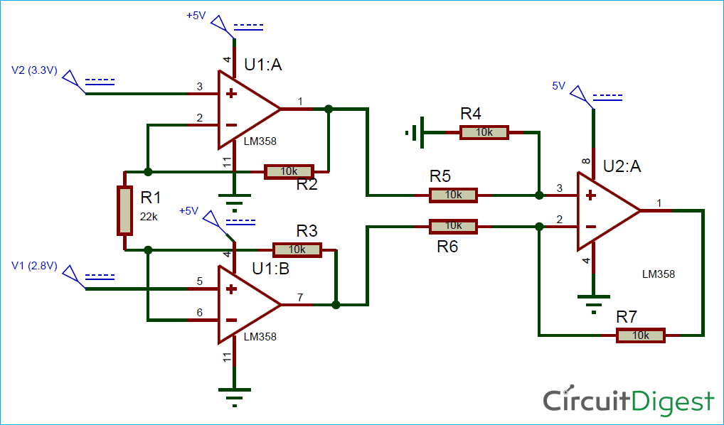 distant raven
broken zenith
Ok, one sec
distant raven
broken zenith
Ok, one sec
What about your battery circuit?
Are you using a change over circuit?
broken zenith
I honestly couldn't tell you. I just used the same chip as the one in the Feather, and based my charging circuit off of that. I'll upload my full schematic in a second.
The power circuitry is in the top towards the left.
 latent grotto
Any of you know where I can find the ST7789VW 1.47" screen found on product 5393? https://www.adafruit.com/product/5393, I did some searching and could not find this exact display for sale by its self.
broken zenith
latent grotto
Any of you know where I can find the ST7789VW 1.47" screen found on product 5393...
I don't know, but I LOVE your profile picture!
latent grotto
https://www.aliexpress.com/i/3256803585064480.html?gatewayAdapt=4itemAdapt I think I found. Of course when I ask discord lol
latent grotto
broken zenith
I don't know, but I LOVE your profile picture!
Thank you! I made it my self!
dry pelican
It's possible that the screens always come with a board because glass is fragile, and it's easier and better to ship the screen with a breakout than shipping the screen without. There probably isn't much demand for low-volume ST7789VW screens by themselves. Unless you want to go to Aliexpress
It might just be better to buy a cheap display breakout and transplant the display to your adafruit board
latent grotto
dry pelican
It might just be better to buy a cheap display breakout and transplant the displ...
This board in specific has the screen soldered under the screen somehow. I dont know how to take it off the board. But I will look into that. Thank you!
dry pelican
If you have a hot air gun, some chipquik alloy, or some mad soldering skills, then you can probably pull it off
latent grotto
dry pelican
If you have a hot air gun, some chipquik alloy, or some mad soldering skills, th...
Im terrible at soldering lol. But ill try. I have one of them next to me at the moment.
dry pelican
Flux might help you
latent grotto
I have solderwick and a solder sucker. Thats all I have for desoldering.
dry pelican
Air guns are useful, but only for SMD work and heat shrink
dry pelican
Maybe you can get it off with isopropyl alcohol, but you need high concentration
latent grotto
isoprophyl alchohol 99%
dry pelican
latent grotto
Maybe I could put it on a hot plate
Might work
dry pelican
latent grotto
isoprophyl alchohol 99%
I would try that first
latent grotto
dry pelican
Maybe you can get it off with isopropyl alcohol, but you need high concentration
Great minds think alike. I have 99% for this stuff.
dry pelican
But isopropyl might damage the display. But since you want to remove it, itxs probably already damaged
Somehow I don't have high concentration isopropyl
latent grotto
I have a few of them. Although I would still prefer the screens working in the end lol
Seems like this is gonna be as annoying as the tack welded usb ports on arduinos
They are impossible to replace
woven bluff
Don't do it, displays can not tolerate any kind of liquid get in between layers
latent grotto
ok
rancid lagoon
woven bluff
Don't do it, displays can not tolerate any kind of liquid get in between layers
You can still see the marks on the left side of my 2ds screen from where it got wet (don’t ask) after 2-3 years
latent grotto
Any of you know if this would work on the top of your wrist? https://www.adafruit.com/product/1093

Pulse Sensor Amped is a greatly improved version of the original Pulse Sensor, a plug-and-play heart-rate sensor for Arduino and Arduino compatibles. It can be used by students, artists, ...
woven bluff
is MnZn core better than Ferrite core in SMPS?
 remote wasp
What is the maximum current I can draw from raspberry pi pico VBUS ?
woven bluff

I'm about to send this to fab, but I'm still not sure the EN pin will work
when EN is pulled to ground, both the load switch and the boost should turn off
 blissful frigate
woven bluff
is MnZn core better than Ferrite core in SMPS?
blissful frigate
woven bluff
is MnZn core better than Ferrite core in SMPS?
Mangan-Zinc (MnZn) is one of the usual ferrite compositions
rustic linden
what's the resistor for, and I'm confused about the zener diode from VBAT
woven bluff
that's not zener, it's shockley symbol in kicad
the resistor pulls EN high to battery, the diode prevents 5V logic input from connecting to the battery
distant ivy
what ic could i use to charge 3 lipo cells in parallel from a mainly 3v3 board?
woven bluff
are you sure your 3V3 have enough current to charge lipo?
most 3V3 is from LDO 5V, unless you are using something like ATX power supply
spice turtle
distant ivy
what ic could i use to charge 3 lipo cells in parallel from a mainly 3v3 board?
You would need a boost converter to do so, but the voltage to charge lithium batteries is pretty close to your input voltage, so your duty cycle will be pretty low that most IC's might not be able to do it. They do have a minimum, and its not 0, its usually 50%.
Do you have another voltage source to select from?
distant ivy
spice turtle
You would need a boost converter to do so, but the voltage to charge lithium bat...
yes i mean more the charging in control and status etc on 3v3, i definetly have a usbc port and am probably adding something like a barrel plug for the charging...
but that's all tbd atm
(which second plug, which voltage it has)
I have no real constraints in choosing the parts etc. I just want some IC that is commonly used so i can get my hands on it
(I am designing a PCB from scratch)
spice turtle
Well I can give you some pointers then. If your micro (or other sub systems) use 3.3V, you probably will also be using 5V, even if for interfaces and charging. Unless you are using switching regulators, that means your barrel plug voltage should be around 6 to 7VDC, Unless you are using USB-C for power.
In which case, there are common circuits for using USB -C for charging. You can use Adafruits schematics as an example. But really, once you have 5V, thats all you really need. Its far simpler that way
distant ivy
spice turtle
Well I can give you some pointers then. If your micro (or other sub systems) use...
hmm so just a usbc connnector
hmm
well makes sense i guess
and then like 3 tp4056?
spice turtle
You would actually only need one. You said 3 Lithium batteries in parallel correct?
Think about what voltages do in a parallel circuit. Then also think of how current acts in a parallel circuit
distant ivy
spice turtle
You would actually only need one. You said 3 Lithium batteries in parallel corre...
but the 4560 only charges at 1 amp which would take me 4.5 hours ca. to charge my batteries
woven bluff
is your usb-c rated 3A?
spice turtle
distant ivy
but the 4560 only charges at 1 amp which would take me 4.5 hours ca. to charge m...
How big are your batteries?
You are also forgetting a crucial part too: the tp4056 may be able to do 1A, but it may also go into thermal overload and shut down for a bit.
distant ivy
spice turtle
How big are your batteries?
You are also forgetting a crucial part too: the tp4...
4500mah -> 3 1500mah cells
woven bluff
all charger>1A is in BGA or FN packages
distant ivy
woven bluff
all charger>1A is in BGA or FN packages
shouldn't be a problem
woven bluff
first you need to negotiate with host to determine charging current, so you don't burn your motherboard
a lot of charger chip has that function
spice turtle
they dont have to go that far-just use a USB plug. Still would be limited at roughly an 1 Amp, which I think thats OK
woven bluff
he wants fast charge?
if you want high charging current delivered by USB-PD, you'll need something with PD interface
distant ivy
no not usb pd
just standard usb 2.0 via a c plug
and that had a max of 3 or 2 amps i believe
woven bluff
usb-c can deliver up to 3A without PD interfacing
distant ivy
yee that's what i wanna do
cc1 and 2 are currently pulled with to gnd with 5k1 resistor
woven bluff
oh, that chip does not have PD interface, it has CC interface, which is used to determine current at 5V
distant ivy
no no chip just the connector haha
woven bluff
distant ivy
cc1 and 2 are currently pulled with to gnd with 5k1 resistor
that means your device is capable of 3A sink, does not mean the host will provide 3A
distant ivy
woven bluff
that means your device is capable of 3A sink, does not mean the host will provid...
mh yes, but only i am going to use that board
which i then can make sure that the host always is able to provide 3a
woven bluff
distant ivy
which i then can make sure that the host always is able to provide 3a
you'll need 3A charger then
distant ivy
woven bluff
you'll need 3A charger then
thanks! just to make sure i can use on ic to charge my 3 cells in parallel
woven bluff
3 cells in parallel = 1cell
distant ivy
is that correct or does that have any bad implications
distant ivy
woven bluff
3 cells in parallel = 1cell
okay thanks!
spice turtle
distant ivy
is that correct or does that have any bad implications
not really. Assuming all cells are good to start with, they inherently will self balance. They all have to be roughly the same capacity, so you cant mix a 700mAh and 1000mAh battery
woven bluff
have fun designing! all >1A chargers are SMPS, so you'll need inductor, current sense, etc
MAX77751 looks good, very small component count
distant raven
woven bluff
have fun designing! all >1A chargers are SMPS, so you'll need inductor, current ...
The BQ51051 wireless charger can do up to 1.5A and the only inductor is the receiver coil
Lol
And I’m using it in 0.5A charging mode for my watch
broken zenith
broken zenith
Hi, is there any reason why a W25Q16JVSSIQ would not save its contents on a powe...
Still looking for a solution to this. I put a 10k resistor on R2 (check my schematic, it's DNP) but that didn't seem to do anything.
distant raven
broken zenith
Still looking for a solution to this. I put a 10k resistor on R2 (check my schem...
You really need a p Chan mosfet and a Schottky diode to do voltage selection between battery/usb power. I didn’t see that on your schematic.
broken zenith
Alright, good to know. Is that the cause of the problem I'm having, or is it for safety?
broken zenith
distant raven
You really need a p Chan mosfet and a Schottky diode to do voltage selection bet...
Oh wait - I just remembered that the USB port won't supply voltage to the AP2112 (I think). Is that better than nothing?
distant raven
That’s likely the culprit. I had also noticed your 5V doesn’t go anywhere
broken zenith
Really? I only run the board with the battery plugged in and the 5V definitely goes to the battery charger... (I'll be back in 5 mins)
distant raven
broken zenith
Really? I only run the board with the battery plugged in and the 5V definitely g...
I meant it didn’t go to the voltage regulator
broken zenith
distant raven
I meant it didn’t go to the voltage regulator
Yeah but the battery is plugged into that, so shouldn't it still work?
distant raven
I guess if the battery is always plugged in?
broken zenith
Yeah it is
dry pelican
Does anyone see any issues (Screw holes and silkscreen are not finished yet) with this board? It's meant to be a modular Tesla coil power output stage + driver, but I'm not completely sure if it'll work.


Also, should I add a ground plane and VCC plane to the driver section of the board. It might create issues since the driver datasheet says to not have a plane near the output. I might just leave the section without a plane since copper fills make it harder to solder.
broken zenith
distant raven
I guess if the battery is always plugged in?
Sorry to ping you but still stumped by this and wondering if you have any other thoughts
distant raven
broken zenith
Sorry to ping you but still stumped by this and wondering if you have any other ...
i'm not really sure. hard to say for sure.
broken zenith
Alright, thanks
dry pelican
Does anyone see any issues with these boards as well? I'm not sure if the via stitching is good enough or if JLC is able to do that via-in-pad in the middle.


 distant raven
if you had a reset button you could put it back into boot when you plug it in and then his reset. I've had some issues of the program not loading.
spice turtle
dry pelican
Does anyone see any issues with these boards as well? I'm not sure if the via st...
Ive done the via's in pads for thermal regulation. They can do it no problem. If thats a power IC, Id add as many as you can practically fit
dry pelican
It's not really a power IC. The dual mosfets handle actually switching power through the bldc coils
spice turtle
that reminds me I have to solder up my own BLDC controller but Ive been putting it off 👀
OH
dry pelican
Nice
spice turtle
you need screw holes
spice turtle
I forget those too
dry pelican
I designed it for screw holes, but completely forgot
spice turtle
Yea, I looked at the board and thought "how are you mounting this?"
supple pollen
"How are you mounting this?" https://www.adafruit.com/product/1116
dry pelican
This is my first try at an SMD power electronics thing
dry pelican
supple pollen
"How are you mounting this?" <https://www.adafruit.com/product/1116>
That looks useful...
dry pelican
A89301 by allegro. It's an I2C controlled BLDC driver. I think it also has FOC.
spice turtle
Just what I thought. So VBB is your VCC. They have it being filtered by a small cap
dry pelican
I guess I now have to find a way to put that in
Nvm I have the cap
It's C2
I looked up the datasheet. It has FOC
I wanted to make a small, I2C controlled, not very expensive BLDC driver for small motors. That's why I made it
spice turtle
gotcha
They do have an eval board I was going to check against
Usually those are pretty good starting points
where is R1 on the board? I cant find it
nvm 😅
looks good. I cant seem to find anything out of the ordinary
dry pelican
It's more of the layout that I'm concerned about since the board is dense and high power
Apparently Allegro thinks that this FOC capable chip is a good fit for generic fans
 dry pelican
There is a problem that I just discovered. The I2C pullups are supposed to be pulled up to the 2.8v VREG voltage, not 3.3v like other devices. Would the device be able to handle 3.3v or do I have to add level shifting hardware?
The datasheet says it's fine
This is the back (now with holes in addition to all the small via holes). There seems to be an issue with the solder jumpers I used

Any advice on that?
slightly updated
 dry pelican
Would a TVS diode to protect a mosfet driver from overvoltage (on VCC) caused by parasitic inductance be a good idea worth implementing?
spice turtle
generally, I havent seen those on BLDC drivers.
Ive seen some shown with NPN transistors that have reverse biased diodes in them.
supple pollen
dry pelican
This is the back (now with holes in addition to all the small via holes). There ...
What's the issue?
dry pelican
supple pollen
What's the issue?
The solder jumpers show that the fr4 is exposed and that there is no copper in areas that should be filled with copper.
dry pelican
spice turtle
generally, I havent seen those on BLDC drivers.
It's not for a BLDC driver. It's for a tesla coil driver and in general
supple pollen
dry pelican
The solder jumpers show that the fr4 is exposed and that there is no copper in a...
I must be looking at the wrong place
rancid lagoon
i see it
on the jumper pads
it looks like where the traces are it's inverted so there's no soldermask but no copper either
dry pelican
rancid lagoon
it looks like where the traces are it's inverted so there's no soldermask but no...
Yes
That's the issue
spice turtle
Lithium Battery SOC: Do I really need an expensive chip just to give a percentage left? Or can I measure charge and discharge current via current sense amp and integrate it over time? Then your SOC could basically be "Discharged capacity divided by Total Capacity * 100
I dont need that much accuracy, 5-10% is fine. Im just trying to avoid buying a $3.50 IC 😅
supple pollen
spice turtle
Lithium Battery SOC: Do I really need an expensive chip just to give a percentag...
You could measure, integrate and calculate, the result will tend to drift over time, but if you measure the cell voltage as well, you can use that as a correction factor, and maybe to detect when the cell gets charged and reset the stored capacity.
spice turtle
supple pollen
You could measure, integrate and calculate, the result will tend to drift over t...
Thats what I thought. Initially, you can enter an assumed, fully charged pack. Since you wont charge it anymore, the only option will be to discharge it. So, you stop it when it gets at 3V, compare discharged capacity to charged capacity. Use that as your 2nd time calculation to show how much capacity/time/soc is left.
Then basically measure charge capacity once discharged like you said.
I think the only "gotcha" is knowing when the battery is charging and discharging.
supple pollen
Your current sense setup should show that: charging current goes one way, discharge goes the other way.
spice turtle
Ahh yea I was typing that out. The little research I did suggested Id need to switch on and off a 1/2VCC point, but then I found an app note from TI where they just use a 2.5V Ref on a 5V supply 🤔
in case anyone else wants this
supple pollen
spice turtle
Ahh yea I was typing that out. The little research I did suggested Id need to sw...
Are you referring to the switching of the reference, or creating the reference?
spice turtle
supple pollen
Are you referring to the switching of the reference, or creating the reference?
Go down to page 30.

In my head, I couldnt figure out how you can switch the ref 😅
(I also picked a part at random btw)
supple pollen
So you were referring to both, I guess?
spice turtle
yes
I see no reason to switch the ref on and off. Using a TL431 is probably the best option.
spice turtle
What should i look out for when using a very low (10m ohms or less) sense resistor? The CS amp gain would have to be high, so would noise be something I should be concerned about even if I am using it in a DC system?
unreal flax
spice turtle
What should i look out for when using a very low (10m ohms or less) sense resist...
Beyond noise per se, there's also things like offset error in the amp to be potentially concerned about if the sense voltage is unusually low. Most current-sense amps tend to want to work with a range of 10s of mV.
The layout of the traces touching the sense resistor also can matter. "Kelvin connection" is a good term to research if you're not familiar with that technique.
spice turtle
and, Im guessing the size of the traces matter as well.
unreal flax
Not so much. They're carrying essentially zero current.
knotty tiger
the traces that pass the sensed current should be large; less so the sense traces
spice turtle
Thing is Ive used them before, but the problem Im running into is that they dont have the gains I need (20 would be perfect), so Im having to lower the sense resistor while finding an IC thats in stock. Most of what Im finding has a higher gain than Im used to working with. So, Im in unknown territory with that.
latent grotto
Anyone here use fritzing?
My component wont go onto the board

Also yes I know I mispelled sd
lol
just noticed
dry pelican
latent grotto
Anyone here use fritzing?
I used to use Fritzing, but I now like using software like EasyEDA and KiCAD
Also I have no idea why the components are not going onto the board
latent grotto
dry pelican
I used to use Fritzing, but I now like using software like EasyEDA and KiCAD
Thats cool, I usually use a mix between EAGLE and Fritzing
dry pelican
spice turtle
Lithium Battery SOC: Do I really need an expensive chip just to give a percentag...
Have you looked at the MAX17048? It is $3.34 though.
dry pelican
latent grotto
Thats cool, I usually use a mix between EAGLE and Fritzing
That's what I used to do
spice turtle
dry pelican
Have you looked at the MAX17048? It is $3.34 though.
Yea, I saw it and thats what I was trying to avoid. Looks simple to use. Downside is that awful package :/
Reason why I was thinking micro+CS amp is because newer micro's have a 12bit ADC in them. I also already have code for discharge measurement from another project 🤔
But....then theres dev time to think of
dry pelican
rancid lagoon
Idk maybe redo those traces?
Fixed. It was something with the footprint I was using
 spice turtle
Oh and cost. CS amp + Micro are looking to be $2 but in both cases, the micro is needed anyway 🤷
dry pelican
You could do something with measuring the battery voltage directly and determining percentage, but I have no idea how that would be implemented
rancid lagoon
Lipo batterys don’t have a straight discharge curve so the analog circuitry would be very complex
Probably better to use a microcontroller and dedicated chip
distant raven
Yeah, voltage drops quickly after it reaches like 3.3V
Current consumption also rises
Then shuts off ~3V for the ones Adafruit sells
dry pelican
That's the reason I said I did not know how to implement it. The voltage stays more constant around 3.7v and the reason that maxim chip costs so much is probably because of their proprietary algorithm.
distant raven
probably
spice turtle
coulomb counting, as was mentioned above, is the other way to do it. If you ever built a discharge tester, its basically that, but also counting the charge current too.
spice turtle
I have to read this but someone did it for their undergrad program 🤔
https://umtjur.umt.edu.my/wp-content/uploads/sites/141/2020/10/6-V2N4.pdf
rancid lagoon
Is there a way to clean pcbs other than isopropyl alcohol?
knotty tiger
there are stronger solvents, but they're usually more hazardous to your health. what sort of cleaning? flux removal?
stronger solvents can also damage parts or dissolve soldermask or silkscreen
rancid lagoon
Some blue stuff (idk what it is probably paint or smthn) got on a pcb and i tried isopropyl alcohol

Is soap and water ok for a bare pcb?
Nvm i got it off with soap and water but it did slightly damage the copper but it’s just my pcb ruler so it’s fine
 knotty tiger
yeah generally soap and water is safe, as long as you rinse and dry thoroughly for actual circuits. that looks like some of the gold plating came off? it's likely fairly thin and only meant to protect the copper before soldering, unless you pay extra for "hard gold", meant for stuff like edge connectors
dry pelican
Should I have a ground plane in this area? If so, top and bottom ground plane or top VCC plane and bottom GND plane or vice versa?
 dry pelican
What TVS diode should I use to protect a MOSFET gate from overvoltage? I want it to conduct/suppress transients right at the limit of the MOSFET's gate voltage maximum because I will be driving the mosfets with up to 18v.
knotty tiger
dry pelican
What TVS diode should I use to protect a MOSFET gate from overvoltage? I want it...
usually there's some margin between the absolute maximum and the maximum recommended voltage, i think? does your datasheet say?
dry pelican
It says absolute maximum is +-30V. It says nothing about recommended maximum. I'm using IRFP460.
supple pollen
If you're driving it up to 18V, perhaps choose something like 19-20V?
dry pelican
The driving voltage will be variable since I'm going to be adjusting the voltage to a mosfet driver that drives a gate drive transformer that drives the MOSFETS.
Actually, it now isn't that much of a problem, as I don't think I'll be pushing the mosfet driving voltage very high. I think a 1.5ke20 TVS will work fine.
knotty tiger
the output characteristics are only plotted for up to VGS=10V, so i assume you get minimal improvement above that for the actual gate voltage? your driver might be transiently going higher than that, to push enough current to charge the gate
latent grotto
On this esp32 s2 schematic it has a EXP pin? What is a exp pin?
 supple pollen
I'm guessing it's a thermal pad, since it's grounded. I don't know why it's denoted "EXP"
unreal flax
Sometimes they're called "exposed pads", so EXP is probably an abbreviation for that.
latent grotto
That would make a lot of sense because the esp32 has ground pads under it

Thank you!
 stone zealot
Hi, I dont post a lot so sorry in advance if I break a rule.. Just let me know please and I will correct my logic.
I have a power supply that puts out 24V and 20A and I have some stepper motors that need 48V. Is there any down side or duty cycle or Amp issues if I add a BOOST CONTVERTER to my 24V output to make it 48V and will I loose and amps doing this boost?? I read but it is very confusing so far. If I add a boost converter can I run the motor for 8 or more hours at a time and be as good as if I was not using a booster?? Thank you.!
Someone said wrap my own transformer BUT not high voltage experienced yet to be messing at that yet.
blissful frigate
stone zealot
I have a power supply that puts out 24V and 20A and I have some stepper motors ...
If your supply can deliver 24 V * 20 A = 480 W the boost converter after it can at best deliver the same 480 W, which would mean 48 V * 10 A.
spice turtle
stone zealot
I have a power supply that puts out 24V and 20A and I have some stepper motors ...
You lose amps, correct. The power has to come from somewhere in order to boost the voltage, so you have a higher power draw. There are inefficiency's in the system so you end up using a little more current.
As for run time, it depends on a lot of factors such as how long you are running it, motor size and how much speed/torque you are running it at. If you have long duty cycles, like once per minute your battery will last a long time. Running continuously and it wont last as long.
spice turtle
blissful frigate
If your supply can deliver 24 V * 20 A = 480 W the boost converter after it can ...
Not entirely. Theres a conversion inefficiency that has to be dealt with. Assuming the boost converter is 80% efficiency worst case, using the formula Eff= Pout/Pin and moving terms, the most he can get is 384W output, or around 8A at 48V.
blissful frigate
spice turtle
Not entirely. Theres a conversion inefficiency that has to be dealt with. Assumi...
Please note that I wrote "at best", which is of course unobtainable
limpid nest
Anyone have a chip or method they like for generating 10+ distinct PWM signals? Frequency requirements are 18~30 kHz.
nevermind, the answer is just don't use a teeny weenie dev board
I think
 storm crystal
limpid nest
Anyone have a chip or method they like for generating 10+ distinct PWM signals? ...
storm crystal
limpid nest
Anyone have a chip or method they like for generating 10+ distinct PWM signals? ...
Check out the Pi pico for example
limpid nest
That's what I was looking at, have the datasheet open now
supple pollen
limpid nest
Anyone have a chip or method they like for generating 10+ distinct PWM signals? ...
PCA9685 might be worth a look, but I don't know if it can manage that frequency range
limpid nest
What possible benefit is there to this design? This is a 1x8 buffer with two !OE pins

additionally, with the buffer element, I'm not used to those having a second input, what is that?
worldly schooner
limpid nest
additionally, with the buffer element, I'm not used to those having a second inp...
The output enable input? Ax is the input to Yx buffered output.
worldly schooner
That’s the enable input.