#help-with-hw-design
1 messages · Page 6 of 1
 distant raven
 knotty tiger
oh, 22µF on both input and output of your 5V regulator? that's going to have a k...
knotty tiger
oh, 22µF on both input and output of your 5V regulator? that's going to have a k...
Data sheet suggests 10uF/50V on Vin, 22uF on Vout
 low anchor
The 12v power should normally come in on the right hand side connector
But in this case yes I connected it on EXP1
knotty tiger
low anchor
But in this case yes I connected it on EXP1
oh. that could definitely cause problems if you didn't connect the 12V supply's GND first
low anchor
Yup that sounds like what happened. From what I remember I connected 12v to EXP1 and ground to the top left of EXP2
In that order :/
What can I do to decrease the inrush current?
distant raven
low anchor
What can I do to decrease the inrush current?
A load switch would help a lot
knotty tiger
low anchor
Yup that sounds like what happened. From what I remember I connected 12v to EXP1...
um. top left of EXP2 is +5V, not GND, at least the way your screenshots are oriented
low anchor
I meant top right, my bad
low anchor
distant raven
Data sheet suggests 10uF/50V on Vin, 22uF on Vout
Hmm the datasheet I found when I designed it recommended the two 22uF ones, weird. I'll double check that
distant raven
low anchor
Hmm the datasheet I found when I designed it recommended the two 22uF ones, weir...
Is yours the 1A variant?
Or 500mA?
 knotty tiger
low anchor
Hmm the datasheet I found when I designed it recommended the two 22uF ones, weir...
knotty tiger
low anchor
Hmm the datasheet I found when I designed it recommended the two 22uF ones, weir...
i think skerr was looking at the example with the EMI filter, which does have 10µF in a few places, but has much more overall capacitance (err, or yeah maybe different capacitors depending on the current rating; that would make sense!)
distant raven
knotty tiger
i think skerr was looking at the example with the EMI filter, which does have 10...
No? Just typical application circuit
But that’s the 500mA device
I didn’t look at the 1A device
Even the 1A device says 10uF/50V for input
knotty tiger
oh, the first search hit i got was for the -2000R3, which recommends 22µF/50V for input
 hushed smelt
Is there a diode that will only allow power one way for 4 pinouts?
I can use 4 separate diodes but it would be far more convenient and space saving to have 1 diode chip handle all that.
 vast flume
Yes
I've only seen them for esd-protection diodes but I'm sure they exist for other applications
Its a zener diode so you can't use it in general applications I dont think; but I'm sure theres other diode chips in the same package
 spice turtle
hushed smelt
Is there a diode that will only allow power one way for 4 pinouts?
spice turtle
hushed smelt
Is there a diode that will only allow power one way for 4 pinouts?
power path is what you may be looking for, or a power management IC. They might be fairly expensive for more than two sources.
hushed smelt
Thank you. I’ll probably just stick with 4 cheapy individual little diodes then.
 fervent lance
I don't get it
https://datasheet.lcsc.com/lcsc/2201121900_BL-Shanghai-Belling-BL1551B_C2944066.pdf
the input voltage is 1.8V to 5.5V
but the output of B, A1, A2, will be the same as the input voltage?
it doesn't look like it's soecified
spice turtle
Yes, its an analog switch, so it just matches the input. Think of it as if it were a relay, but an electronic one.
 merry grail
I have a problem with a usb-c project. It did work, I even got a blinky running at one time. But now when I plug it in all other usb devices disconnect. I've looked for shorts, can't find any. What else should I look for?
merry grail
Turns out it was the jack itself.
 supple pollen
Thanks for sharing what you found, I was curious.
 woven bluff
@supple pollen seems icestudio support for ECP5 Evaluation Board is on paper only..... There is not even a single input clock.
now I have a paperweight sent to lab corner collecting dust
distant raven
woven bluff
<@348911944486486016> seems icestudio support for ECP5 Evaluation Board is on pa...
You could fork icestudio, add the board, and compile it
There are a few ecp5 boards in the supported boards directory
Actually looks like it’s already there https://github.com/FPGAwars/icestudio/tree/develop/app/resources/boards/ECP5-Evaluation-Board

GitHub
:snowflake: Visual editor for open FPGA boards. Contribute to FPGAwars/icestudio development by creating an account on GitHub.
 distant raven
woven bluff
distant raven
woven bluff
Looking at the docs, it bases the clock speed of the fpga off the external clock. So it does make sense you can’t select or add it
Have you tried looking at the documentation for IceStudio?
woven bluff
the board has internal 12M and 200M
the nwjs GUI is not working properly for some reason
is IceStudio production ready?
distant raven
It’s open source, last release was April
It appears to work for a lot of people. Looking further at an issue about external clocking; icestudio takes care of it. I don’t think there’s any need to specify it
spice turtle
Has anyone used those cheap 433Mhz Modules in a 3D print successfully? Just wondering If I can get away with a thin wall and still be able to use them to get reception. Im not pushing out much data either
 unreal flax
You should be able to without trouble... plastic doesn't interfere with radio that much, especially at lower frequencies.
spice turtle
Thats what I was thinking too. I dont need to go far, literally 20ft would be OK
I know not many people know about them, but I have these modules I bought due to their ease of use; E43-433T13S,. They are small but wayyyy to OP for what I need.
spice turtle
I should do a write up but Im using the "H5V4D" receiver and it seems to be running OK. I tied the data line high because Ive found it floats and gives crappy data a lot. I am beginning each "packet" with 0xFF and 0xAA. These seem to work OK. Baud Rate is 2400 BPS. Im only at a foot or two of distance, LOS. Transmitter is standing up, and the receiver is laying down.
As long as both are still, it works. I think this will work 🙂 I forgot where I got these though
supple pollen
I think the RadioHead library supports those simple radios, and there's another library optimized for them (I forget what it's called)
It may have been the VirtualWire library, which has been superseded by the RadioHead library anyway. There's also the RFTransmitter and RFReceiver libraries by zeitgeist87.
hushed smelt
The RFM95 and RFM69 modules that Adafruit use are compatible with radiohead, there’s mention of it in the library which I had to dive into for my rfm project. I have no idea what Radiohead is but seemed compatible out of the box. Just make sure you get a module with compatible mhz 400 or 900 for your needs.
If you only need to go 20 ft that should be within WiFi range. Radio will work line of sight. Putting a brick wall between you wouldn’t be advised but a pane of glass shouldn’t be a problem.
spice turtle
You know, I did forget to check if my complier has support for the nrf series line of RF transceivers and apparently, it does. It seems that in much the same way there are arduino boards, another company has kind of made the same thing for PIC micro called "Click boards". Well, turns out, there is a nRF24L01P board and it looks like there is software for it pre-written. These are also just as small.
ex:
https://www.mikroe.com/nrf-c-click
But..I wonder as well: how hard would it be to just DIY it myself?
https://www.mikroe.com/ook-tx-click
Ie, what if I just...remade the schematic? I dont exactly have rf testing equipment, but, how hard can it be?
unreal flax
spice turtle
You know, I did forget to check if my complier has support for the nrf series li...
I don't think there's anything particularly unusual about the Click boards versus any other nRF24 breakout board, it's just a convenient header. So you can use the same nRF libraries with any transceiver board using that chip.
 dry pelican
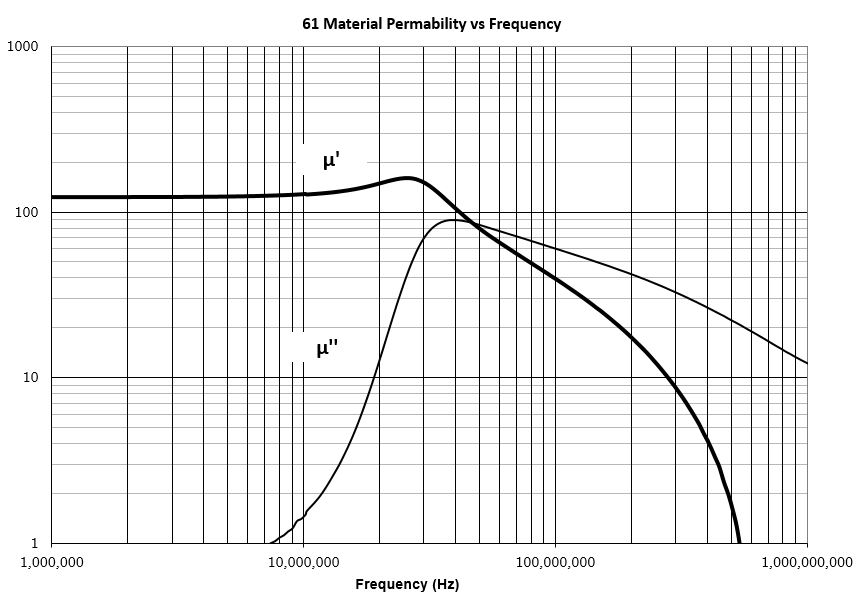
A high frequency NiZn ferrite developed for a range of inductive applications up to 25 MHz. This material is also used in EMI applications for suppression of noise frequencies above 200 MHz. Excellent stability characteristics. Strong magnetic fields or excessive mechanical stresses may result in irreversible changes in permeability and losses. ...
This is the datasheet for the 61 ferrite material that I'm planning to use in a gate drive transformer for my Tesla Coil. I'm not sure what size toroid/ring I should get. Basically I want it to be "good" for 700kHz to 2MHz. The coil's current resonant frequency is around 1.2MHz, but I may want to change that to something lower that the driving components are better rated for. I'm driving a half bridge (probably 2 x IRF460P). I assume that I want a transformer that can work at high frequencies, has a high coupling coefficient, and does not emit much radiation (EMI). Would a bigger or smaller toroid be better? Or is there a better material? I've never read a ferrite core's datasheet before and I don't know what most of the things mean because I am a hobbyist and not an EE.
I think smaller is better, but I'm not sure.
The biggest toroid that I would use (because of space) would be around 22mm in diameter and 10mm in height, but smaller is preferred.
about the diameter of a quarter
coin
TLDR: Is 61 ferrite a good Tesla coil GDT material for around 1.2MHz driving frequency? What size should the toroid be?
80 material seems good as well. It's rated for power applications from 1-5MHz, which is where the coil is operating. Although there's not much margin on the lower side. 61 just says "inductive applications up to 25MHz"
 verbal moss
Hello! UberGuide says to use 300-500 Ohm resistor close to 1st NeoPixel's DIN.
Does it matter if Thin Film vs Thick Film resistor for NeoPixel DIN?
Wondering if Thin Film should is recommended? My first PCB attempt has Thick Film resistors, they result in sloped/ramped signal in the pic. Doesn't look good to me, at least that's what the scope is telling me, which I'm also learning how to use.
Note, do NOT use BSS138 for high frequency signals (>400khz), they won't be level shifted. Something else I've learnt.
I read and searched through NeoPixel UberGuide https://learn.adafruit.com/adafruit-neopixel-uberguide/neopixel-matrices (pdf) didn't see specifics on resistor type, maybe doesn't matter?
Already posted to https://forums.adafruit.com/viewtopic.php?t=195153 but figure folks here will know
Yellow = signal from QT PY pin
Blue = signal at 1st Pixel DIN, just after 470 Ohm Thick film resistor.
Measuring signal before resistor looks identical to Yellow, indicating slope introduced by resistor, and that the BSS138 isn't shifting squat.
Cheers!


Adafruit Learning System
Everything you always wanted to know about Adafruit NeoPixels but were afraid to ask
distant raven
verbal moss
Hello! UberGuide says to use 300-500 Ohm resistor close to 1st NeoPixel's DIN.
...
Data line is relatively low current so thin film is more than adequate
It’s not going to be drawing huge amounts of current
As for using the bss138 for level shifting, how is your level shifter set up?
I use the bss138 and my signal level shifts for neopixel. BSS138 is more than sufficient for 1MHz and below.
verbal moss
distant raven
As for using the bss138 for level shifting, how is your level shifter set up?
Thanks @distant raven, here's schematic for BSS138. Using 10k resistors, however some people suggest lower resistance? Only just got the scope, so not sure if/how lower resistors will help. Planning to use 74lvc... Level shifter in next revision.
Some people say not to use resistor between lever shifter and first DIN even. So many different opinions out there... Lol
 distant raven
verbal moss
Thanks <@728676724522352733>, here's schematic for BSS138. Using 10k resistors,...
distant raven
verbal moss
Thanks <@728676724522352733>, here's schematic for BSS138. Using 10k resistors,...
Why is 3.3V going to pin 5 (G1)?
Wait
Ignore me
G1 is probably the gate pin

seems right, this is what I do
verbal moss
Thanks for sharing your schematic, it's reassuring to see I got that ok.
Curious what BSS138 you're using? Maybe I picked wrong BSS138, used https://lcsc.com/product-detail/MOSFETs_MCC-Micro-Commercial-Components-BSS138AKDW-TP_C779245.html. For mine, I see 3V3 boosted to 5V if I set the pin to constant high. But I don't see any boost at NeoPixel 400khz or 800khz frequencies. I haven't investigated at what frequency the level shift starts to drop off. I didn't see an explicit frequency range in the datasheet, maybe I need to infer/compute based on the switch on delay (3.8ns). Currently digging through misc BSS138 datasheets to eyeball for differences...
BSS138AKDW-TP MCC(Micro Commercial Components) US$0.0848 - 50V 220mA 1.9Ω@10V,500mA 350mW 1V@250uA 2.9pF@25V 2 N-Channel 22.8pF@25V -55℃~+150℃@(Tj) SOT-363 MOSFETs ROHS datasheet, price, inventory C779245
distant raven
verbal moss
Thanks for sharing your schematic, it's reassuring to see I got that ok.
Curiou...
supple pollen
dry pelican
TLDR: Is 61 ferrite a good Tesla coil GDT material for around 1.2MHz driving fre...
You'll need enough size to contain the magnetic field to deliver your gate pulse without saturating. Basically, you multiply your drive current by the pulse length, then multiply that by the number of turns to get ampere-turns * time. Multiply that by the aL value to get the field density, and see if it's too much.
Würth Elecktronik publishes some good books on the subject (ABCs of Inductors and Trilogy of Magnetics). Art of Electronics also covers it. However, it's often quicker to eyeball similar circuits or commercial gate drive transformer offerings and use them as a guide. For many circuits in that range, their little 10mm dia by 3.8mm thick toroid is entirely sufficient.
The 80 material has much higher permeability than the 61, but I doubt you need much permeability at that frequency.
distant raven
supple pollen
The 80 material has much higher permeability than the 61, but I doubt you need m...
Why settle for 80 when you can go 200
I’m joking of course hehe
Toroidal cores are lots of fun. I’ve considered getting some bare cores and trying to wrap my own
There are some P200 ferrite cores that are just a few $ a piece that seem like they’d be a great starting point
supple pollen
Yeah, I don't think Fair-Rite offers a 200 mix. But there are some amazingly high permeability mixes out there. I've been playing with core memory built out of toroids, but the usual mixes available today don't generally offer the squarish B-H curve that's best for it.
distant raven
Most P200 cores are washer shaped. Like a squished donut from what I can tell
Toroids are not my strongest area so my knowledge of making inductors with them is limited
supple pollen
I did eventually find out that the Fair-Rite 85 mix seems like it would be good for core memory. They don't list it any more, but Mouser has some stock.
distant raven
I’ve watched a few videos but I’ve not done it
supple pollen
My early experiments are encouraging. You want a "hard" ferrite with a large magnetic remanence for good performance.
 distant raven
That’s really cool
Have you made a toroidal transformer at all?
I had thought it would be fun to make one
supple pollen
Yeah, a few hand-wound ones. I may make more, although my last homemade transformer used E cores and a bobbin.

Heh, I found a pic of my last toroid project: just wound a few turns on a "Flexiformer" to provide filament power for an argon laser. Ugly, but it worked.

@knotty tiger would be amused
 scarlet totem
Is there somewhere I could read about thunderbolt and displayport conversions?
 plush vector
I need help please guide
I'm consufed


Is the implemented of diodes and capacitor correct?
supple pollen
The diagram doesn't show what's connected to D2, nor where the lower connection to the battery nor C1 goes (presumably a 0V reference?). However, the breadboard shows largely the same thing: the cathode bands of the diode point toward the capacitor lead (which appears not to be the negative one). It's unclear where the capacitor's other lead goes (best guess is a black jumper to the red rail on the left, which is presumably the 0V reference?).
 untold leaf
sorry, might be missing something... bss138 works great for me in level shifting ws281x data signals. If it works up to 2MHz, that's ok for 800KHz, no? (2000KHz)
jlcpcb assembly error sounds completely plausible to me. I have found the ws2812 5050 and 3535s to be very heat sensitive in reflow... you can actually hear the little twangs as the die wires break if you get it wrong. a damaged LED will likely have a break in its lens. there's a trick where you sharpie the lens to expose its structure better when troubleshooting (does damage appearance). you can also jump around a failed led by shorting its DI and DO pins with a bodge wire.
weirdly, the ws2812E (economic version) seems a little more reflow tolerant. but I have found all of these to be total pains and I prefer individual LEDs with dedicated LED drivers like IS31FL3733.
distant raven
I prefer the sk6812, it’s nearly identical to the ws2812 but it has a constant current driver. Colors are more consistent and I’ve had no issues reflowing them.
The IS31FL3733 is a great chip though. I thought about using it to make a tiny RGB display with the UHD1110 tiny RGB LEDs I have
Or there’s a version that has tons of pins for doing large RGB LED displays row/column counts
supple pollen
I wonder if those are the same tiny RGB LEDs used in the AdaFruit LED glasses
 supple pollen
Wow, that is small. Yeah, the glasses ones are like 1.5x3mm or so, much "bigger"
Have any pictures of that display? It sounds amazing.
distant raven
The data sheet lists “displays” as a use so I want to try it out haha
I need a powerful enough RGB led display driver though 😅
supple pollen
I'd probably go with something like the HUB75 style displays use, with shift registers, drivers, and multiplexing
distant raven
If I’m going to make it, it’s gonna be at least 1.5”x3”
Which would be like.. easily 400+ LEDs
I could probably do 20 per inch, so it would be like 30x60 pixels
supple pollen
Wow, I want one. In that sweet spot between 2mm HUB75 displays and OLED.
Come to think of it, an OLED controller might work too
distant raven
Placing 1800 LEDs would be fun
supple pollen
That's a job for a machine or a fanatically dedicated human
distant raven
At that rate I’d need to hire someone
supple pollen
I'd go with a PCB fab service, even if you have to source the LEDs yourself and send them the reels (I've done this)
distant raven
It would be like $100 in LEDs Alone lol
They are roughly $0.05385 a piece in a tiny reel of 1000
supple pollen
Same price in a full reel of 10,000 😦
supple pollen
Not much cheaper even then. There were some specific chips I wanted for a small run, and I ended up buying out the supplier's entire stock of a few dozen chips for a little over $200
distant raven
Sell a 30x60 LED display for $190
supple pollen
You know what, I'd buy it.
distant raven
These LEDs are pretty bright too. G,B channels are 48mA max, and R is 60mA
The ICE5LPxK have 24mA open drain for and RGB led and it’s really bright at 24mA
supple pollen
I could replace the LED array in my projector and get better than its current 8x8 resolution!

I had no idea the FPGA drivers had that kind of current capability, that's amazing
Although I suspect there's a limit on the aggregate current they can sink.
distant raven
I was surprised that it’s 24mA per channel
 worldly schooner
I think there’s a thermal limit past which point you’ll need active cooling
supple pollen
However, FPGAs are super at driving things like power shift registers (which is, of course, basically how the HUB75 style panels work)
distant raven
I know this, because Just running the RGB LEDs, the board gets warm to the touch
It’s only feather sized on two layers so heat sinking isn’t the greatest
supple pollen
Stick-on heatsinks can be useful
distant raven
I have some ones for raspberry pi laying around somewhere. Or I did may have gave them away
I’m the lab at work, we put those little clip on desk fans blowing at our FPGA boards lol
worldly schooner
Oof, for more LEDs you might want more layers or at least more copper
Didn’t you make a pixel featherwing that desoldered itself last time?
distant raven
A neopixel board that was run on full white face down on a table lol
The PCB was also black so double whammy
50 neopixel, full white, is like 2.5A at 5V, so 12W 🙂
All turned into heat being face down hahaha..
Apparently 12W on a 1.5”x5” board radiates enough energy to hit 140+°C
It’s when I realized that using low temp solder on LED displays was not a great idea
worldly schooner
Oh, 140C is better than I expected, considering I’ve seen pcb reflow hot plates work before…
distant raven
It’s the only issue with designing electronics, you can never predict what customers will do with your product
As for the uhd1110 RGB led matrix, I need to figure out a display driver to do 30x60 Rows x columns
Adafruit’s choice allows to do 13x9 the is31fl3741
supple pollen
LD7138 can run 128x128 RGB
distant raven
supple pollen
LD7138 can run 128x128 RGB
Do you know where to source it
I found the data sheet but Digi-Key doesn’t have it from what I can tell
supple pollen
It's a 10-year-old chip, but the maker's site is on the data sheet: http://www.ldt.co.kr/_kor/index.asp
엘디티, OLED, Driver IC, Display, safemate, 화재예방, IOT, SSN
They offer both LED and OLED driver chips, so they may well have something appropriate for your needs.
distant raven
LED drivers look like 48 channel is the widest one
supple pollen
Yeah, the higher density ones seem to be their OLED drivers, which may not deliver the current you want. http://www.ldt.co.kr/_kor/designer/skin/02/01_01.asp
엘디티, OLED, Driver IC, Display, safemate, 화재예방, IOT, SSN
distant raven
I may try the IS31FL3741 first since that is supported and seems to work well. Maybe figure out a way to chain multiple together with an i2c buffer to do image blocks
Doing 8x 9x13 on an i2c buffer would give you either 18x52 or 36x26
supple pollen
Maybe look at the TC5020A and similar chips used in LED panels. They're basically power shift registers.
distant raven
Weird that Digi-Key doesn’t have that one either
supple pollen
These mostly circulate in the far east ecosystem to provide large quantities of inexpensive LED arrays. The matching row driver chip is an ICN2012.
distant raven
LCSC has it
16 channels
5 RGB LEDs per register
Or drive one color on each, do 16 RGB LEDs with 3
supple pollen
Yup. That seems to be how they're deployed on LED panels.
distant raven
So 3 registers to drive a 4x4 array
At $0.37 for a single, it probably works out
That would end up being an interesting board
supple pollen
There are several offerings out there. RUC7258 and DP5020B seem to be similar.
These are SOIC chips which would kind of dwarf your tiny LEDs, while the OLED drivers are small, they seem to be offered as dice for COB assembly.
distant raven
It would be pretty funny to do it with the TC5020A because it’s a TSSOP-24 and would be bigger in itself than the LEDs in a 4x4 array lol
Probably where the IS31FL3741 has the advantage
supple pollen
The MBI5124 is available in more space efficient packages (mini SSOP and a 4x4mm QFN)
distant raven
4x4mm would be slightly smaller than the 4x4 array
Might work
The routing on that would be a lot of fun
supple pollen
The savings increases as your array size grows, depending on what sort of multiplexing you care to use (1:8 or whatever)
distant raven
0.5mm a clearance between each LED would be ~ 6.5^2mm for each 4x4 array
supple pollen
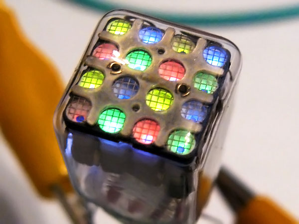
I can see the appeal of starting with the 4x4 array you mentioned, just as a proof of concept. It would be adorable in a similar sense to the amazing if bonkers ITM2M display that uses an array of gas thyratrons to implement a 4x4 color display in a single glass envelope. https://www.industrialalchemy.org/media2/pict13/itm2mlit.jpg
 distant raven
Oh wow 😮
I think they make 1:16 i2c mux which means if I used the IS31LT3741, I could do a 4x4 matrix if 9x13
So 36x52 which is pretty close to the 30x60
supple pollen
That would be pretty amazing. Routing on that would also be a lot of fun.
At least it's not Charlieplexed like the IS31FL3731, that would be 😬
distant raven
It would definitely have to be 4 layers
Sounds like a fun weekend project
Now I just need a 10000pc reel
I have like 95 of the LEDs on hand lol
dry pelican
distant raven
There are some P200 ferrite cores that are just a few $ a piece that seem like t...
Where did you find those?
distant raven
Digi-Key
distant raven
dry pelican
Where did you find those?
worldly schooner
distant raven
I think they make 1:16 i2c mux which means if I used the IS31LT3741, I could do ...
I don’t think that exists in a monolithic package, but you could use something like 4x LTC4314 to achieve a similar result. Dedicated enable pins are probably faster than an I2C controlled MUX like the pca9548, but you might need a binary decoder or gpio expander for 16 enables haha
distant raven
Yeah, my guess is I’m going to need a daughter board just for the driving peripheral
That would simplify routing LEDs
Also would mean no 2 sided assembly
worldly schooner
Wait, isn’t IS31FLxxxx a single color led driver?
distant raven
The IS31FL3741 can be configured for RGB

I could configure 4 on one board
Address is set by connecting addr pin to either VCC, GND, SDA, or SCL
So I could probably use a 1:2 mux with some finagling in code to manage
Or use a chip that can have 2 I2C buses configured at the same time
 split obsidian
Hey everyone. Looking for assistance with a soldering question. I'm looking to do a DIY SMT hotplate with an inexpensive hotplate. That being said I'm worried about "Hotspots" and would like to use a mic6 bed (a spare voron v0 120mm^2 buildplate) between the hot plate surface and the PCB to act as a heat spreader and also to ensure flatness across the hotplate surface (especially as some of the hotplates I'm looking at seem to have "ridges")
Good idea? Bad idea?
spice turtle
It looks like theres plastic on it and for the temps hot plates are at it might melt
(but Im going by a sellers description). If its pure Alum then you can use it
supple pollen
split obsidian
Hey everyone. Looking for assistance with a soldering question. I'm looking to d...
The usual approach is just a slab of aluminum.
split obsidian
Yeah, it's pure aluminum. Might be covered in plastic for shipping protection to protect the finish or something
Thanks! I think I'm going to be ordering an infrared hotplate tonight
 limpid nest
when speccing a crystal (32.768 kHz), is there any issue with getting one with a tighter tolerance than the specified?
Additionally, I am unsure about these parameters. What do they mean?
 distant raven
limpid nest
Additionally, I am unsure about these parameters. What do they mean?
distant raven
limpid nest
Additionally, I am unsure about these parameters. What do they mean?
this is for the internal RTC
and for some low power stuff
are you looking at using the bare chip?
limpid nest
No I just assumed it needed an external crystal based on this info
distant raven
if you plan to use the internal RTC, yes I would
if not, the module should have a 32MHz crystal on it
limpid nest
Ok then I will use external. What do you mean by "this is for the internal RTC"?
distant raven
the nRF52840 has an internal RTC that utilizes the XL1,XL2 pins for using the 32.768kHz crystal
it's not required to hookup is what I'm saying
limpid nest
Oh I see ok
But I may want the RTC so I think it's worth it. But what do those parameters have to do with the choice of a crystal
distant raven
it's just letting you know what the pin capacitance is and internal capacitance is
Adafruit uses a crystal that requires 22pF load capacitors
limpid nest
Ah. Would they be in series here?
distant raven
so probably a 14-16pF load 32.768kHz crystal
those capacitors internal would be in parallel more than likely
something like this would work
12.5pF is fairly close, gives about 1.5pF of stray capacitance, and would use 22pF load capacitors
there's ya load capacitor
supple pollen
limpid nest
But I may want the RTC so I think it's worth it. But what do those parameters ha...

Adafruit Industries - Makers, hackers, artists, designers and engineers!
Learning to design your own PCBs and being able to put together a schematic to solve a specific problem is both a valuable and rewarding skill. There are a number of resources out there to help yo…
limpid nest
thanks all
limpid nest
XL1,XL2 are the crystal pads right?
supple pollen
Yes, I think "XL" is for "crystal, low frequency"
dry pelican
supple pollen
You'll need enough size to contain the magnetic field to deliver your gate pulse...
I don't know a lot about inductors and magnetics (I know that a current going through a wire creates a magnetic feild, and that that field can be focused and transferred through a ferromagnetic core). So what's aL; what would be a too high field density; what does magnetic permeability do (increases inductance/coupling?)?
distant raven
Oof, dyno being overzealous
supple pollen
Grump, I don't want to type all of that again
Short version: attacking it from first principles with all the math and technical terms is often not the best approach, which is why I added the simplified approaches I use
 unique patio
@supple pollen's message, sanitized:
Alas, I don't know a lot about it either, just enough to realize it's complicated and subtle. AL is like an "inductance factor" and describes how much a particular core material affects the inductance of wires on it. The saturation value varies with the core material, some saturate more easily than others. Permeability describes the willingness of a material to accept a magnetic field, it's related to permeance, which in turn is yet another term for AL. This is why I followed up the technical gobbledyg--k (useful if you want to Google the details, less useful for actually determining a concrete answer without further study) with some of the simplifying approaches I tend to use.
dry pelican
So, based off that information and my own speculation I guess I want enough windings and enough core that the inductance is enough that it creates a strong magnetic field (that does not saturate the core) but not so much inductance that it does not respond to high frequencies. I guess the toroid size should be whatever other people usually use and enough to make all the windings fit and have no magnetic saturation.
I probably also need to smack a big top load on the coil to make it operate at a lower frequency that MOSFETS, drivers, transformers, and logic chips are better suited for. I calculated that at 1.2MHz, the period is 833.33333ns, which means there is about 415ns for each MOSFET to switch. Also weird parasitic stuff starts happening at those frequencies. Although the coil (12V MOSFET slayer) works really well (possibly better (meaning bigger arcs) than it would with a top load (but I haven’t tested that recently (and my top load is a 3D printed torus with aluminum foil JB-welded to it))) with no top load.

It’s running off 12V 3A from an SMPS wall wart so the arcs are not really long
 obtuse sky
Hi, what should I be looking for for a small cheap speaker that a microcontroller can use to make beeps at different pitches? I've seen them but I don't know what they're called. As I understand it, a buzzer only does one pitch, and a proper speaker is overkill.
dry pelican
obtuse sky
Hi, what should I be looking for for a small cheap speaker that a microcontrolle...
You can get little buzzers like this without the oscillator circuit.

10PCS 5V 2 Terminals Passive Electronic Buzzer for Arduino
You cannot drive those directly from a microcontroller though because they draw 0.25A at 3.3v. They’re basically mini speakers. So you’ll have to have a bjt or mosfet to drive these from the microcontroller
You can also get a proper speaker by ripping one out of an electronic greeting card.
Sound quality will not be excellent, but it’ll be fine for making beeps.
obtuse sky
Thanks, I see. I wonder if there are lower power ones too. Like in small battery-powered items.
dry pelican
You can probably put a resistor in series with it to limit the current. Since you’ll only be applying power to it half of the time when creating the tone, the current draw will be 0.125A at 3.3v. You can decrease the duty cycle for lower current usage.
supple pollen
obtuse sky
Thanks, I see. I wonder if there are lower power ones too. Like in small battery...
Yeah, there are a variety of little speakers available, from tiny PC-mount ones that look like piezo beepers but are actually small electromagnetic speakers, to little bare speakers (like AdaFruit 1891), partially enclosed ones (3923), and even small fully-enclosed ones (3351). You can also repurpose drivers out of things like headphones, toys, etc.
untold leaf
worldly schooner
Wait, isn’t IS31FLxxxx a single color led driver?
nah most of their datasheets (except for the charlieplex oneI bet) show rgb examples. Have used *33 myself with multiple Vf
limpid nest
An RGB Keyswitch would probably have the following pins, right? Switch1, Switch2, VCC, GND, DATA, Cathode, Anode.
unreal flax
limpid nest
An RGB Keyswitch would probably have the following pins, right? Switch1, Switch2...
Generally I'd expect it to either have just data/vcc/gnd (and omit cathode and anode) if it was a smart LED, or omit data/vcc/gnd (and have several cathode/anode pins) if it was a dumb RGB LED.
limpid nest
hmmm
Hard to tell
Cherry doesn't provide this information, somehow
Like I want to use their switches because as far as I can tell they are very high quality
But if I can't use them, I can 't use them
supple pollen
They should provide that info
supple pollen
You could always buzz it out with a current limited supply and voltmeter. It's a little effort, but I've done it with things I couldn't find documentation for and wanted to use.
limpid nest
Yeah I'm still designing so I'm not giving up on Cherry getting back to me with real info
 rustic linden
limpid nest
An RGB Keyswitch would probably have the following pins, right? Switch1, Switch2...
rustic linden
limpid nest
An RGB Keyswitch would probably have the following pins, right? Switch1, Switch2...
so the neokey breakout has 5 pins, Switch + and -, VCC, GND and Neopixel Data
supple pollen
Oh! When I read "lighted keyswitch", I was thinking something like this. If this is a keeb switch, there are probably standards (although there may be more than one, especially if addressable and non-addressable LEDs are in use).
 limpid nest
I'm working on a whole keyboard and macropad setup for someone. How crazy of an idea is it to do a USB 3.2 Gen2x2 hub?
knotty tiger
what components are you using? very few hobbyist class microcontrollers can achieve that kind of speed
limpid nest
I want the hub to be multi capable
scarlet totem
limpid nest
I'm working on a whole keyboard and macropad setup for someone. How crazy of an ...
Working on something similar, though not keyboard, just USB hub, switches and video out
limpid nest
Like I want it to be a genuinely high quality product, not just good enough for the keyboard products.
This is just a gift for my sister's husband but I haven't gotten him any good presents in the 4 years they've been together so I gotta show up
knotty tiger
oh, so you're not building anything at those speeds, only considering buying an existing hub as a gift?
limpid nest
It's not an existing hub, I want to make it, but otherwise yes
knotty tiger
have you done any designs anywhere nearly that fast before (10GHz for 3.2gen2, i think)?
limpid nest
Nope!
I'm aware it's difficult, I'm just trying to figure out if it's impossible with my tool chain. That is Fusion or KiCad, a 100MHz scope, a cheap logic analyzer
knotty tiger
a 10GHz-ish scope probably will cost you more than a new high-end car. even USB-2.0 high-speed (480MHz) is likely to be challenging with hobbyist equipment
limpid nest
Ah shucks
I wonder if I can find a complete high speed design somewhere that I can order and craft an enclosure for
My whole thing here is that all the peripherals match
knotty tiger
if it's about aesthetics, you might want to consider buying an off-the-shelf hub and making a custom enclosure for it (assuming you can maintain the EMI performance)
limpid nest
You mean popping off the case?
knotty tiger
yeah. or embedding the whole unit inside another custom case (though extension cables are technically forbidden, so you might be taking some reliability risks if you went that route)
 dense gulch
limpid nest
I'm working on a whole keyboard and macropad setup for someone. How crazy of an ...
dense gulch
limpid nest
I'm working on a whole keyboard and macropad setup for someone. How crazy of an ...
I haven't made one but this looked interesting https://ww1.microchip.com/downloads/en/DeviceDoc/00002875C.pdf
limpid nest
Looks nice but it turns out I am not at all set up for multiple gig design
dense gulch
you should be able to keep the differential traces on the top layer w/ the PortSwap feature
tbh, we use 10 GBPS ethernet at work and have never looked at the eye diagram 😄
we have a 500 MHz scope so it's pretty useless for that
if you avoid vias on those high speed traces and get controlled impedance from your fabricator you'd have a good chance at making it work, if you were still interested in trying it out 🙂
we looked into renting a high speed scope and it ended up being ridiculously expensive per month, I think a 3 GHz one was in the $2k range but 10 GHz was another magnitude
limpid nest
Hmmmm
I'll consider it thanks. My only reticence is, if it doesn't work out, I can't figure out why and change my design
dense gulch
limpid nest
I'll consider it thanks. My only reticence is, if it doesn't work out, I can't f...
Yeah that's true, and it is probably somewhat expensive to produce. You'd save money buying that pre-made hub, and have it guaranteed to work.
To produce your own, you'd need to choose some dielectric with relatively steady dielectric constant vs. frequency and low dielectric loss, FR408HR is a good option since it's available at many fabricators (including OSH Park with a 4-layer board). As a fall-back, if your hub doesn't work out at high speeds, it looks like this chip has the option of reducing speeds:
The USB7206 supports 10 Gbps Super-Speed+ (SS+), 5 Gbps SuperSpeed (SS), 480 Mbps Hi-Speed (HS), 12 Mbps Full-Speed (FS), and 1.5 Mbps Low-Speed (LS) USB downstream devices on five standard USB 3.2 Gen 2 downstream ports and only legacy speeds (HS/FS/LS) on one standard USB 2.0 downstream port.
That won't help you get the boards working at SS+ speeds, but at least it's a fall-back to get it working at all. If you try FS and LS modes and don't see a good signal, you'd at least know why it isn't working at those higher speeds.
If you make your board have the same footprint as that hub you found, you can swap them out until you get yours working. It depends whether you just want a fully functional unit vs. trying your hand at that high speed design.
limpid nest
Hmm interesting
I'm fundamentally unhappy with that assembly I linked but it is acceptable if it's all there is. I want SS+ and some USB C
dense gulch
limpid nest
I'm fundamentally unhappy with that assembly I linked but it is acceptable if it...
Ahh this one looks like it has some options here: https://ww1.microchip.com/downloads/aemDocuments/documents/UNG/ProductDocuments/DataSheets/00003852A.pdf, 3 USB 3.2 gen 2 interfaces, 2 of which have type-c support, and 1 usb 2.0 interface. Manufacturer link: https://www.microchip.com/en-us/product/USB7252C
Microchip Technology Inc. (MCHP) is a leading provider of microcontroller, mixed-signal, analog and Flash-IP solutions, providing low-risk product development, lower total system cost and faster time to market for thousands of diverse customer applications worldwide. Microchip offers outstanding technical support along with dependable delivery a...
I think the one I linked earlier is actually not recommended by the manufacturer, sorry. The ones ending with C appear in production
limpid nest
ah nice thanks
merry grail
I'm looking for the best option for addressable LEDs. The cheapest options I can find are about 30-40c per SMD. Are there other cheaper options I should consider?
supple pollen
It depends somewhat on how flexible your notion of "addressable" is: if you mean individually controllable, and you want a lot of them, it can be cheaper to use a control IC and a bunch of less-expensive "dumb" RGB LEDs.
merry grail
supple pollen
It depends somewhat on how flexible your notion of "addressable" is: if you mea...
Could I bother you to post an example schematic? I'm having a hard time finding one.
supple pollen
The AdaFruit LED glasses work that way: https://learn.adafruit.com/assets/105132
 sand mica
So I’m trying to learn fritzing, I loaded in the adafruit parts to get feathers. I’m not sure how best to represent a battery plugged into an m4 express feather’s battery jack? The m4 express fritzing part has a visual of the battery jack, but there aren’t any connections defined. Similarly, I can’t figure out in fritzing how to connect a neopixel string’s jst plug to a prop-maker’s jst plug? What’s the standard way people handle plug based connections in fritzing?
 void sentinel
Ok finally my last order is shipping from Digikey. I have a resistor I can control for a hot plate, I have a hot air gun, I have magic toaster oven.
I don't have a stencil.
Is the reflow over preferred?
Someone mentioned a combo on the hot air and hot plate.
I have a qfn56. And other junk.
I heard solder paste has the flux in it?
I saw someone use a stencil and sand in a pan and stencil in reflow, but they didn't use flux separately.
What is preferred?
Pros/cons leaded solder?
I don't want to tag anyone, but I especially appreciate the advice from someone who has done the rp2040 or other fine pitch parts.
I have been looking on the Amazon at the Chip Quik and there are a bunch to choose from. Most are T3. I found a T4 in the Sn variety. I heard lead flows better.
distant raven
T4 paste is preferred. If it’s just for you, leaded paste should be fine. Stencils are the preferred and recommended method but careful use a a syringe would aloe you to apply paste in a line across the QFN pads
If there are bridges, if you have a chisel tip for your soldering iron, flux and a little heat drug along the pads after you reflow can get rid of any bridges
If you don’t have a chisel tip, any tip would work. Just make sure to use plenty of flux and clean it off afterwards with some strong IPA
void sentinel
I saw a video and the paste was I thought way too much, then when it melted it separated perfectly. That threw me off. Lol
supple pollen
T5 paste flows better than T4 (smaller particles). Leaded solder wets better and melts at a lower temperature.
void sentinel
I think I might be overthinking it, because I haven't done it before, but I feel plenty confident.
distant raven
If you have parts for multiple boards, don’t feel too bad if you use one or two just to practice. You’ll be better off each time down the road
void sentinel
distant raven
I use low temp bismuth based solder
void sentinel
I was going to desolder a pico to practice, but unmelting is usually harder. Maybe not in oven.
distant raven
Chip Quik SMDLTLFP Solder Paste Sn42/Bi57.6/Ag0.4 No-Clean Lead-Free Low Temperature Melts 138C 281F https://a.co/d/i5VY7av

Solder Paste Sn42/Bi57.6/Ag0.4 No-Clean Lead-Free Low Temperature Melts 138C 281F eutectic. Metal Content: 87% metal by weight. Particle Size: T3 (25-45 microns) Size: 5cc/15g syringe
It has a much lower temp than leaded paste, plus the silver/bismuth make it shine 🙂
distant raven
Chip Quik NC191LTA10 Smooth Flow Low Temp Solder Paste Sn42/Bi57/Ag1 T4 10g Syringe https://a.co/d/10UzrG0

Lead-Free / RoHS 3 Compliant / REACH Compliant Description Smooth FlowTM Technology Developed with a lower density flux vehicle for better shear spread and improved flow during heating Halogen Free (EN14582 test method) Specifications Alloy: Sn42/Bi57/Ag1 Flux Type: Synthetic No-Clean Flux Classi...
I use a hot plate/hot air
void sentinel
I remember you saying that. Why no oven?
distant raven
Space/money
Even doing the toaster oven conversion, it’s still going to be close to $200
void sentinel
You said you did 200 on plate and 250 on air I believe. I'm guessing that's in Celsius?
I can see space, but I have the old toaster and all kinds of controls and stuff. I feel like it will just work all the ways and the potential for failure is most likely me putting on too much solder. And the rework has to be done manually any way so I actually like the idea of that way even though the oven seems like "the professional" way. I can see it better and control maybe.
Ok thanks. I will update when stuff gets here.
distant raven
void sentinel
You said you did 200 on plate and 250 on air I believe. I'm guessing that's in C...
I run 160°C on my hot plate but it’s PID tune is a bit off. So it comes in around 150°C
 fervent estuary
Hi, a little Neopixel question. I want to use ESP32 controller for 6 strips of around 60 LED each. My main goal is to minimize wiring. Is it better to control each strip with different pin, or to connect them to one another?
limpid nest
It's essentially equivalent? Your code changes a bit but one way isn't better than another based on my experience
fervent estuary
I know that with ESP8266 it was basically only viable to use 1 or 2 pins, otherwise it was not working that well. But ESP32 has that RMT (or whatever its called), so I wonder is the number of pins also limited or not
limpid nest
Which board are you using?
fervent estuary
custom one based on ESP32-D0WD-V3
limpid nest
Ah
So the main benefit I can think of to multiple pins is you could get a faster refresh rate across all your leds
But it's just a PWM signal so you only need PWM capable pins
distant raven
limpid nest
So the main benefit I can think of to multiple pins is you could get a faster re...
It’s actually can be slower to use multiple pins for neopixel
distant raven
Unless you use PIO on the RP2040.
limpid nest
Ah because of consecutive writes?
worldly schooner
The theoretical speed max may be higher with multiple pins, but unless your controller can handle DMA with 6 pins simultaneously, it’s unlikely to get any meaningful performance gain…
distant raven
I had a 5x10 neopixel matrix and I tried doing 5 individual row writes and it was pretty slow
limpid nest
Fair enough
worldly schooner
Outside of dma or pio, all neopixel writes I know of are sequential
fervent estuary
that was one of my concerns. That having a single line would definitely be fast. But I wonder how many can be run through this RMT
because from what I remember, it was able to just dump RAM onto physical line
 rancid furnace
Quick classical circuit question for you all. I have built this NMOS amplifier. This is part of a larger 2 stage design, with a source follower output stage. I decided to do an intermediate test just to make sure everything is working, and so only the first stage is shown here.
When I make it on a breadboard, testing at 1khz, I see much less gain than I expected from LTspice. Instead of 6Vpp as expected, I only get 1Vpp at most.
Why is this?
Is this cause for concern, or due to the test equipment introducing load (meaning the output stage will iron it out)?

 signal topaz
rancid furnace
Quick classical circuit question for you all. I have built this NMOS amplifier. ...
signal topaz
rancid furnace
Quick classical circuit question for you all. I have built this NMOS amplifier. ...
you can add some load into LTspice and see what happens
rancid furnace
It doesn't affect it at all
signal topaz
and you are using same transistor as in the simulation? are you using oscilloscope to observe the output?
rancid furnace
yes, and yes
signal topaz
check if your DC operation point is the same as in simulation
vast flume
Thank you to everyone who helped me, V2 of my pcb just came in and the 5v switching converter worked!
 limpid nest
Hey! Congrats! Nice work.
distant raven
Great work!
vast flume
So theres an issue 😭
The microcontroller on the back (ESP12F) is getting power bc the indicator led on it flashes when I connect it to my computer over USB, but my computer wont detect it
I've probed it as well and its getting a stable 3.1v the whole time
distant raven
You’re using the cp2102n for usb to serial?
vast flume
Yeah
distant raven
Do you see it show up on the device manager?
vast flume
No
But when I plug in another pcb that I made which also uses the cp2102n, that one does show up

Heres my schematic
distant raven
Nothing seems out of the ordinary on first glance
vast flume
Hmm
And I just double checked my cp2102n chip and theres no bridged pads that I could see
Wait actually I think I might know what it is
I got that chip pretty hot while installing
I bet I cooked it
I'll try replacing it
distant raven
👍🏻
vast flume
@distant raven Replaced it but still getting the same result 😦
distant raven
vast flume
<@728676724522352733> Replaced it but still getting the same result 😦
Did you place the VUSB resistors in the wrong place by chance?
vast flume
Wdym?
distant raven
vast flume
Wdym?
The 47.5K and 22.1K resistors
They are right in the schematic but I’m wondering if they got misplaced during assembly
vast flume
Oh true
I'll double check
Ah so one of those resistors is actually upside down lol
Would that cause any issues or no?
rustic linden
resistors are non-polarised
so it definitely shouldn't matter what way around it is!
vast flume
I meant flipped so the black side was down
supple pollen
Might impact heat dissipation slightly, but I would expect the circuit to still work normally.
vast flume
ok
untold leaf
where does the supply net 2102N_VIO come from? might have missed it. or maybe it's not getting a voltage?
unreal flax
untold leaf
where does the supply net 2102N_VIO come from? might have missed it. or maybe it...
That's a good question indeed. The ECAD tool wouldn't have flagged it as a disconnected net, since it loops back to the reset pin, but I don't see any connection to 3.3V like I'd expect.
untold leaf
unreal flax
That's a good question indeed. The ECAD tool wouldn't have flagged it as a disco...
if need be, @vast flume, you could solder a bodge wire from one end of the resistor R9 to 3v3. signed, someone who has made plenty of mistakes like that 😅
vast flume
2102N_VIO just bridges pins 9 and 5 together

Heres a screenshot from another pcb I made where the usb did work
 vast flume
hmm that does seem convincing
So in theory if I bridge pins 5 & 6 it should work?
To test this theory
untold leaf
no. give it 3v3 from your esp-12 supply since it needs to use 3v3 io signals
That's what this pin does, it sets the i/o voltage levels.
 upper pier
After spending a few days trying to optimize the sleep power on RP2040 with middling success I’m excited to learn about Adafruit TPL5110 Low Power Timer Breakout, but I have a couple questions. The guide for this board just shows a microcontroller board getting powered through it on a power supply, but it obviously is meant for use with a battery. Attached is the example circuit from the TPL5110 data sheet. I’m wondering if there’s a way to use this to charge the battery using my feather’s built in charge controller and still use this board to switch it all the way off when not in use. My crude thoughts:
-
Can I put the board in between the feather and the battery and just put a diode across the mosfet pointing back towards the battery? So that if the charge controller tries to charge the battery it can do so, but the battery can only discharge when the TPL5110 is allowing the connection? I know enough about charge controllers to suspect this is a bad idea…
-
Maybe better could I wire the feather’s usb voltage source back to the Delay pin on the TPL5110, so the battery gets connected whenever the microcontroller is plugged in and can charge?
3. A third, better idea from someone here?
- If none of the above 3 things works it would be really really nice to have a board that looks like the TPL5110 breakout board but with a battery charge circuit built in. That or have the pad reconfigured for this board so it sits on top of and connects cleanly to the existing "Micro-Lipo Charger” boards, or get included in the trinket charge controller backpack, etc etc
 limpid nest
I had a though. How far fetched of an idea is it to make your own quartz watch movement. What about rechargeable?
unreal flax
limpid nest
I had a though. How far fetched of an idea is it to make your own quartz watch m...
I'd generally assume that would require some pretty delicate and specialized micro-mechanical fabrication.
limpid nest
Hmm
I think it's just a stepper motor?
And some clock dividing
But I don't know about resetting the position. I guess that's the hard part
Probably way easier just to buy a movement for 10 bucks.
supple pollen
Usually "quartz movement" just means an ordinary 32kHz crystal oscillator driving a pulser that uses an electromechanical linkage (electromagnet or piezo transducer, generally) that runs a gear train that operates the watch hands.

*Originally published July 2014 First developed in the late 1970s, quartz watches are a relatively new phenomena in the centuries-old craft of watchmaking. Unlike watches with mechanical movements, quartz watches are a whole different breed.[...]
spice turtle
What is the DT pin used for in the USART module of a microcontroller?
 keen carbon
Will any 5 pin LED strip lighting be compatible with any 5 pin LED controller? Or does RGBW/RGBWW/etc make a difference when selecting a compatible LED strip for a given controller?
worldly schooner
keen carbon
Will any 5 pin LED strip lighting be compatible with any 5 pin LED controller? O...
Not personally familiar with 5-pin strips, but I would verify the pinout instead of assuming cross-compatibility.
vast flume
@untold leaf @distant raven Tried bridging R9 to the 3v3 output from my linear regulator, but it didn't work
distant raven
Hmm
vast flume
distant raven
Did you place the VUSB resistors in the wrong place by chance?
Also just checked these resistors, both are correctly placed
unreal flax
spice turtle
What is the DT pin used for in the USART module of a microcontroller?
It looks like that the "data" signal when the USART is in synchronous (clocked) mode.
vast flume
I got it!
I fixed it purely by accident
Accidentally ripped off my usb port
Resoldered it with a lot more solder and a healthy amount of flux
Works now...
...spoke too soon 😭
So before, when I would plug it in the indicator light on the esp12f would flash but my computer wouldn't detect it
Now when I plug it in, my computer detects it but the indicator light isn't flashing
And I'm unable to program it
vast flume
Yeah I think it might mean theres a short somewhere
dry pelican

Instructables
How to Upload New Firmware to ESP8266 (ESP-01S, ESP-01) (Newest 3.0.5 SDK, 1.7.5.0 AT) USE ESPTOOL.PY!: This was really frustrating for me, and I want to show the method that worked for me. I assume that by this point, you have gotten serial hooked up (Best is a little USB programmer dongle) because that's covered in most other guides.
Also, it'...
Here's an instructable that I made on how to update ESP-01 modules with outdated firmware.
Might help with a 12f
Although it's for the at firmware.
dry pelican
Also, I need some help with some power electronics on the 2nd version of my tesla coil. I'll be using genuine IRFP460 mosfets in a half bridge configuration. I just need to figure out what gate resistor I should use and how I should select a diode to discharge the gate faster. I know that I want to choose those 2 components so that the turn on and turn off times are the same (right?) so I don't have the 2 mosfets shorting the power supply. It takes 168ns to turn a fet off (off delay+fall time), but only 77ns to turn it on.
Details: 12-30v input, ~12v drive voltage (maybe more with more secondary windings on the gdt)
What value should I choose for a gate resistor?
And how should I search for a diode (I assume I need something that can carry almost 9A for a few tens of ns every cycle and has a very fast recovery time)?
Mosfet datasheets are confusing 😕
 fierce lance
I'm considering getting some nixie tubes. They require 100v minimum. Where would recommend getting a power supply for them? Should it be a separate PSU or could I get away with a Boost Converter from a 24v source? I've never used these tubes before and I'd like to have fun with some old tech.

eBay
Nixie tube IN-8 for sale (Almost IN-14). Length (tube) - 55mm. Working current (digits) - 2,5-4,5mA. Working current (dot) - 0,3-0,7mA. I am always open for conversation and I am sure that we will find a good way to solve any situation.

eBay
(For Nixie Tubes Magic Eye tubes etc. before fold back occurs)for multiple Nixie tubes, works well with EM84 style Magic Eye tube. Apply a 9-12v DC Center positive input, for an approx. 100-300 V DC output - Adjustable via on-board trim pot.
woven bluff
why this T flip flop has no input?

this is from icestudio, but T-FF is supposed to have both clock and toggle input
unique patio
woven bluff
this is from icestudio, but T-FF is supposed to have both clock and toggle input
is it just being used as a divide-by-2?
distant raven
Looks like a divider
woven bluff
unique patio
is it just being used as a divide-by-2?
this thing is labeled as "T flip flop"
unique patio
yeah but one input is from the inverter?
woven bluff
it's trying to make a T-FF using a D-FF and a NOT gate
but this thing is clearly not a T-FF since it has not Toggle input
I think XOR gate is the right approach
 supple pollen
dry pelican
Also, I need some help with some power electronics on the 2nd version of my tesl...
supple pollen
dry pelican
Also, I need some help with some power electronics on the 2nd version of my tesl...
Using a diode (or two) lets you set the turn-on and turn-off rates separately.
distant raven
fierce lance
Can a board like this https://www.ebay.com/itm/152237036068?hash=item237208d224:...
Only one way to find out 🙂
Something looking of being cheaply made doesn’t necessarily mean that it is. But usually photos do a poor job at conveying quality
dry pelican
I would say the circuit has a high chance of working properly, but there are some safety concerns. Namely the exposed capacitors charged to 100+V.
dry pelican
supple pollen
Using a diode (or two) lets you set the turn-on and turn-off rates separately.
That’s a good tip, but how do I choose the gate resistor(s)?
supple pollen
Basically, the high end is how slowly you can allow the current to charge the gate capacitance, thereby controlling the switching time. The low end is how much current you can allow to flow without damaging something.
dry pelican
With minimum turn-on/off time (but turn on and turn off times are equal to prevent (or lessen) shorts)
supple pollen
Note that turn-on and turn-off times don't have to be equal to avoid shoot-through. In general, a slower turn-on will help minimize this.
dry pelican
I would say turn off needs to be as fast as possible. I will be using a GDT driven by a UCC47425 (dual inverting/non-inverting driver) that says it can provide 4A peak.
I may choose to use a UCC37322 and UCC37321 for 9A peaks
dry pelican
woven bluff
but this thing is clearly not a T-FF since it has not Toggle input
As I see it, the clk toggles the flip flop when T is high. When T is low, it just stays in the same state. T basically is an enable.
unique patio
woven bluff
I think XOR gate is the right approach
I was thinking it was a T-FF wired up to be a divider, hence its T input is already in use.
 steel valve
Why do typical op-amp circuits not include capacitors?
I am making a PCB which has a multiplexer with a voltage divider and op-amp at the output.
My PCB will utilize one capacitor, I only intend for VCC to go into a VCC pour which powers the multiplexer, sensors that interface with the multiplexer, and the op-amp.
Will this cause any issues?
worldly schooner
It sounds to me like a fairly low-current application, so without seeing the schematic itself, I can only assume it’s fine if your supply and single cap can handle it?
 glacial gale
does usb polling update its own local register or can you set it to auto write to RAM?
unreal flax
glacial gale
does usb polling update its own local register or can you set it to auto write t...
You probably will need to explain a bit more to get a good answer to this question... it's assuming a lot of context that we don't have.
glacial gale
ok it seems like the usb controller polls the connected devices for any changes/requests. Then generates an interrupt with that data if there is a change
 halcyon kiln
hello, see my post in #general-chat : #general-chat message
in short, im trying to see if i can use multiple i2c extenders on the same bus
trying to see if i can throw one between the multiplexer, and each i2c header pair
verbal moss
Today's top secret https://youtu.be/rQ-bvKcwN0w featured board with SMT wire terminal blocks. Curious if anyone has recommended/preferred manufacturer/part that they would use for low profile wire to board design. Found WAGO 2060 and 2061, wondering if there's something better? Ideally a lcsc stocked part. Cheers!

The news from Adafruit in New York. Broadcast October 19, 2022
https://www.adafruit.com/new
These are items or concept products that may/might/could be introduced into the Adafruit store in the future (or not)! It's not out yet, so please don't ask questions or ask when it'll be available....
Check out the Adafruit store for all the great pro...
low anchor
Does anyone have pointers for how to pick an ICL? or should I just use an integrated load switch?
low anchor
knotty tiger
oh. that could definitely cause problems if you didn't connect the 12V supply's ...
is this something I could have mitigated with just better PCB design or should I add the ICL/load switch? In regular deployment these boards won't be regularly connected/disconnected from the power supply
worldly schooner
halcyon kiln
in short, im trying to see if i can use multiple i2c extenders on the same bus
Even though it’s technically the same bus, only one leg of the multiplexer is active at a time, so there’s certainly no reason you can’t have an extender on each leg.
On a separate note, you should probably add two more rows of header pins to make it easier to share a V+ and GND reference, as that is also required for I2C.
halcyon kiln
yup thats next on the to do list
gonna use 2 or 3 of those same 3 x 4 headers, but rotate them vertically
for SCD, SCL, vcc, and gnd
worldly schooner
Also, If you’re trying to reuse this design for the other boards as well, you’re going to need a set of pins for your I2C input as well.
halcyon kiln
may also incorporate a level shifter. that would let me run 3.3v or 5v i2c devices without issue, correct?
yea theres already 2 pins in there
worldly schooner
Just don’t forget vcc and gnd

 worldly schooner
It would depend on what the device in question is tolerant of. Stemma QT is tolerant of both, but other breakouts might not be.
halcyon kiln
well i guess i cant really run a rail if im gonna be using those extenders
worldly schooner
Oh, you arranged it that way. I was thinking you’d take a four-row version of the pwm and adc arrangement haha
halcyon kiln
well i will
basically look at those p2m 3x4 headers
ill take th ose same ones, and rotate it 90
so each i2c will be a column, and each row will be sda, scl, vcc, and gnd
worldly schooner
How will you be powering the other boards? If your cables are long enough, you might find vcc voltage may drop a little due to the resistance of the wires
halcyon kiln
well it currently uses a screw terminal, because thats what came in the PWM board package
it uses a terminal > transistor > then some kinda capacitor
but id like to possibly replace that power setup with a USB C, in the same position as a pi 4
so it can fit in a pi 4 case
worldly schooner
Are you driving servos or lights with this board?
And how far apart from each other are they?
halcyon kiln
for pwm, mostly inline fans, and would like to incorporate some control of some led lights
also peristaltic pumps
for ADS, ph and tds/ec probes, and other analog devices such as flow meters, moisture sensors etc....
for i2c, temp/humidity/co2 sensors, and other various sensors
i believe each u nit/board would have about a 5 to 10 foot run between them
and each individual device would have about a 5 foot cable, or less depending
this would be more of a universal thing though. it seems like every little nerdy pi project i do needs i2c, pwm, and ADS in some fashion
worldly schooner
3 meters @ 400kHz sounds doable for the LTC4311.
Just keep in mind that chaining them will require careful addressing of the boards so multiplexers on the same bus don’t conflict with each other.
halcyon kiln
yea im going to break out those solder jumpers, to actual pin header jumpers
the ones to the right
so that i can configure addressing
verbal moss
Appreciate this I2C chat. Have 192 servos connected to 12x PCA9685 boards connected to janky connectors on permaboard scraps. Am somewhat concerned about signal integrity, reflections. Any advice/suggestions on whether resistor(s) at connector hub would help? Asking because neopixel uberguide recommends resistor just before first pixel to help protect against voltage spikes, I think they're caused by induction over long runs. Max distance between I2C breakout and hub is 5'


 steel valve
worldly schooner
It sounds to me like a fairly low-current application, so without seeing the sch...
steel valve
worldly schooner
It sounds to me like a fairly low-current application, so without seeing the sch...
This is the schematic

It is intended to be powered via a 3.3V pin on the board this daughterboard will attach to
limpid nest
Does this item need a power source? https://www.adafruit.com/product/2800

This tiny micro NFC/RFID tag is super small, and contains an NTAG203 chip plus antenna. It's super tiny, flexible and a great way to DIY an RFID or NFC device if you're interested in ...
 soft sable
Hi! Can I use this: https://learn.adafruit.com/multi-cell-lipo-charging/simple-balance-charger On a 4s Lipo?
 unreal flax
limpid nest
Does this item need a power source? https://www.adafruit.com/product/2800
unreal flax
limpid nest
Does this item need a power source? https://www.adafruit.com/product/2800
No, it's powered by the radio waves coming from the reader device.
limpid nest
ok
and how small can the reader device be? I had a cute idea to make an electronic connect 4 game
unreal flax
limpid nest
and how small can the reader device be? I had a cute idea to make an electronic ...
They're often like Arduino-sized to have a relatively large antenna coil, but I'm not sure how tiny you could potentially make them. https://www.adafruit.com/product/789

We've taken our popular Adafruit PN532 breakout board and turned it into a shield - the perfect tool for any 13.56MHz RFID or NFC application. The Adafruit NFC shield uses the PN532 ...
unreal flax
Just off the top of my head, I could imagine having some sort of sensor at the bottom of each column, to measure the weight of the pieces above it or detect the impact of a new one falling on top. That way the game could keep track of the player moves.
limpid nest
Oh I was thinking that there wouldn't be any pieces beyond the two pieces used to interact with the board. I'm now thinking a metal piece that you use to bridge a pair of contacts at the top of a column and then led circles light up at the appropriate height, maybe wirh an animation of them falling
Although
I'm realizing that that won't work
unreal flax
Oh, gotcha. Yeah, if you wanted a fully electronic system, just having buttons on the top of each column would work.
limpid nest
What kind of chip is needed to very accurately measure resistance of a metal?
unreal flax
The problem would usually boil down to measuring a small voltage difference, so you'd use like an instrumentation op-amp to amplify it up to a normal range. But the difficulty depends on how accurate you need, how conductive the metal is, and often things like how you are connecting the probes to the material.
limpid nest
So this is the same project idea
unreal flax
Remember that resistance depends on the size and shape of the object too.
limpid nest
What I want to do is use 2 different metal disks and then detect which color of plastic disk, in the normal game, was used.
So I can have one sensor
And not two
unreal flax
Ah, that doesn't really need much accuracy, just "high" and "low".
unreal flax
You can probably choose the materials such that they'd have easily-measurable resistances.
If you're careful you could have the whole column wired up as one big parallel electrode and measure all the pieces at once.
limpid nest
Oh no let me describe what I mean
So I don't know the right word but I'm going to call the part you put the plastic pieces into the game board.
So my idea is that there's a grid of circles made from RGB LEDs. Then at the top of each column is a pair of electrodes. The play pieces are 2 different metal disks that you touch to the electrodes to make a play. Then an animation of a red or blue disk falls down to the appropriate height.
unreal flax
It's not obvious to me that you actually need to distinguish the colors. Since the players take turns, the game would already know who was next.
limpid nest
That's a good point
rustic linden
I'm trying to figure out some inline way of connecting 2 boards together
fierce lance
verbal moss
Appreciate this I2C chat. Have 192 servos connected to 12x PCA9685 boards conne...
OMG that is so cool!
How do you identify the relay socket for this relay? https://www.digikey.com/en/products/detail/omron-electronics-inc-emc-div/G5LE-1-DC5/280368 It is 5 pin but I'm not sure how to use Digikey's filter to get a socket that is compatible. https://www.digikey.com/en/products/filter/relay-sockets/184?s=N4IgjCBcoBw1oDGUBmBDANgZwKYBoQB7KAbRACZyBOABhogF0CAHAFyhAGVWAnASwB2AcxABfAmCowqCEMkjps%2BIqRA0QDUVqA
supple pollen
That relay is designed to be soldered into a circuit board. However, there are relays available with socket pins, or quick connect style terminals.
supple pollen
rustic linden
I'm trying to figure out some inline way of connecting 2 boards together
I have one project where I'm using dual row 90° headers to plug boards together edge to edge.
Another possibility is to attach a card edge connector to one and plug the next one into that.
rustic linden
I've seen someone have trouble with that as it's not at the same height? and I want them to be flush next to each other, cause it's for a clock
Worst case I just make a backplane for it all
supple pollen
The 90° headers line up nicely (I arranged for the pads to be the proper distance from the edge to do this), as I wanted to use a pair of 4-digit boards for an 8-digit display with the digits evenly spaced (the upper board is one of the digit boards)
 glacial gale
would having separate sram chips for emulating L1-L3 cache be better than trying to fit the entire cpu core + caches on an FPGA chip?
supple pollen
My thinking is that on-chip will generally be faster, if the capacity is available.
glacial gale
yea the problem is that the caches can take up a lot of the LUTs
supple pollen
Some FPGAs offer onboard RAM which will tend to be more efficient than building RAM out of logic elements.
glacial gale
only dram usually though. I guess since cpu cache takes up to 90% of the transistors it makes sense to to have extern sram chips for fpga dev
dry pelican
limpid nest
So I gotta figure out two suitable metals
Maybe use 1 ferromagnetic metal and one non-ferromagnetic metal. The ferromagnetic metal should increase the inductance of an inductor, and the non-ferromagnetic one won’t have as big of an effect. Also would make it non-contact.
fierce lance
If a relay coil voltage is 24vAC does that mean it would get triggered by 48vDC?
supple pollen
That depends on the relay. It probably would operate, but it may draw too much current and damage the coil.
fierce lance
supple pollen
That depends on the relay. It probably would operate, but it may draw too much ...
😦
steel valve
So, I have a hardware-design related problem...
I need to connect 17 sensors to an Arduino.
I have a Arduino, with the bottom of the Arduino being taken up by a custom breakout board which interfaces with 10 sensors.
That means I have 7 sensors left to connect
5 of the last sensors I need to connect are potentiometers, so V, VOUT, GND.
The last 2 sensors are just parts of a Joystick.
I could make a breakout on the top of the PCB, but it would be an odd shape and may have electrical problems due to the shape.
I could make a daisy chain system to split the V and GND between the potentiometers, but that looks unprofessional and very makeshift
steel valve
steel valve
So, I have a hardware-design related problem...
I need to connect 17 sensors to...
This would be the layout of the oddly shaped top breakout PCB


(So that it can fit the shape of the top of the PCB)
Yellow = Signal (VOUT)
Green = VCC
Purple = GND
Dark Green = VCC Source Pin
Dark Purple = GND Source Pin
Dark Orange = VOUT SourcePin
I could technically route on this oddly shaped PCB, but I would need a GND plane and possibly a VCC plane (or at least a partial VCC pour on one layer) to do so, and this is a two layer PCB.
limpid nest
Are black plastic rj12 connectors, uncrimped, a thing?
supple pollen
limpid nest
Are black plastic rj12 connectors, uncrimped, a thing?
Do you mean 6P4C plugs, or jacks, or something else?
limpid nest

1 FT Coiled | 6 FT Uncoiled-Extended | RJ22 | 4P4C | Gold-Plated Contacts | PVC Jacket | UL Listed
supple pollen
Ah, those are the smaller 4P4C plugs. I usually see them in that clear form, but I'm pretty sure I've seen black ones on already made up cables, but I don't remember seeing them separately (which is what I'm guessing you mean by "uncrimped" here).
limpid nest
Hmm ok
supple pollen
I found some 6P4C ones in black: https://www.globalsources.com/Modular-plug/Telephone-Modular-Plug-1127933739p.htm
limpid nest
Nice thanks
halcyon kiln
anyone know exaclty what they are doing with these solder jumpers on the i2c m ultiplexer?
 knotty tiger
halcyon kiln
anyone know exaclty what they are doing with these solder jumpers on the i2c m u...
knotty tiger
halcyon kiln
anyone know exaclty what they are doing with these solder jumpers on the i2c m u...
i think they're there to make it easier to disable the pullup resistors, should you want to do that
halcyon kiln
ok so would you typically have them connected or disconnected
just curious. im replacing all the solder jumps on the board with headers, and just trying to figure out what all each does
supple pollen
It depends on whether you have other things with pullups connected to the buses. You want enough aggregate pullup resistance for decent speed and noise immunity, but not enough to stress the chips doing the communication.
halcyon kiln
 supple pollen
Eh, I phrased that confusingly. More resistance is less stress, but more (parallel) (pull-up) resistors is less resistance and more stress.
halcyon kiln
can see all the headers out to the right
i think i may have excess for the i2c expanders address pins
i basically moved the i2c expanders headers into that layout you see so that each has sda, scl, vcc, and gnd
and there were a few pins left, reset, a0, a1, and a2
but theres also solder jumpers for the a0,a1,and a2
so not sure if i can consolidate those?


(ahh i see the "cut to disable pullups" there to the right in that last pic btw. ill just leave jumpers on and remove them if needed)
i guess my question is, do i need access to those address pins, if im already replacing those address solder jumpers, with header jumpers?
knotty tiger
it depends on what kinds of connector situations you're envisioning, and how much flexibility you want to provide to the user
halcyon kiln

so look like for reset i just need a 2 pin header with gnd and reset mapped to it. for the addresses, i just need to replace the solder jumpers. dont really need to plug up to the actual breakout pins
 kindred kernel
Hello everyone, absolute beginner here. I tried looking myself, but I'm wondering if anyone can point me in a good direction to build a night light with a microphone so that it only comes on at night and if there is loud sound above a to be determined decibel level.
if there is a better channel for this type of question please let me know
unique patio
kindred kernel
Hello everyone, absolute beginner here. I tried looking myself, but I'm wonderin...
For CircuitPython help, #help-with-circuitpython is the right channel
kindred kernel
awesome. thanks for these
fierce lance
Is there a relay socket for these relays? TE KUP-11D15-5 https://www.ebay.com/itm/133793372962?hash=item1f26b4db22:g:fr0AAOSw8BNgzl-6&amdata=enc%3AAQAHAAAAoL%2B87P%2FPsvdbartAEmd7vHxSK30O0Gzh476T5tDlJ8RkDgPV2U3z2r9bU%2Bw5mZRPACAPuuZi5Rz8X4%2B2sootcSOHckWKcA6xwWHHaReOXxQODDknN7bXXAMsMZ6%2FbDJhtNSHQHycEHyVYTB58eLyjqyHyGizIOoSN9hjYeGj87eIukZCQBkGHGBtCdvEgALYz350fmUClX52kLDDUZ%2BAlDQ%3D|tkp%3ABk9SR5bRhcj_YA It looks like it might be socketable as it would be an awkward PCB, you'd need to cut it in the center?

eBay
Price is each Potter & Brumfield connectivity KUP-11D15-5 general relay 5VDC. Condition is "New". 3A, 1/2 HP, 600VAC10A, 1/3 HP, 250 VACShipped with USPS First Class.
unique patio
fierce lance
Is there a relay socket for these relays? TE KUP-11D15-5 https://www.ebay.com/it...
See this page at the bottom for sockets: https://www.te.com/usa-en/product-4-1393117-8.html
fierce lance
@unique patio thank you!
unique patio
it was just a bit of websearching on the part number 🙂
i may have been a reference librarian in another life
fierce lance
Haha. Since this has a coil voltage 5v DC they should be able to be triggered by an Arduino right without separate mosfet + psu?
unique patio
fierce lance
Haha. Since this has a coil voltage 5v DC they should be able to be triggered by...
the coil resistance is 21 ohms, so the current required to actuate the relay is about 240mA, which is a lot more than an Arduino pin can supply. These are pretty hefty relays, what power are you switching?
fierce lance
@unique patio So that'd require a Mosfet and separate PSU, and triggering it via the mosfet?
Power: Not a lot. I've just been trying to find relays I can mount without a circuit board for an art project and I keep coming back to these styles.
unique patio
yes, a mosfet. You'd be much better off with a tiny relay. You could mount it deadbug style with sponge tape and solder to the terminals. But what is it controlling: lights, motors?
woven bluff
The relay that mounts without circuit board is designed to withstand current that circuit boards can not handle.
you can use a solderless breadboard
or buy some of those relay modules with screw terminal
limpid nest
fierce lance
<@329766224093249548> So that'd require a Mosfet and separate PSU, and triggerin...
Check out functional devices. They make high quality modules that you can easily trigger from a PCB using a transistor
They are also, critically, rated
So far safer than rolling your own
fierce lance
Thanks, everyone. Got a different question now. What is a Newark Electronics Trade Account? I'm trying to buy some things from them.
 unique patio
fierce lance
Thanks, everyone. Got a different question now. What is a Newark Electronics Tra...
unique patio
fierce lance
Thanks, everyone. Got a different question now. What is a Newark Electronics Tra...
A trade account is an account where they bill you. As an individual, you would not have one. I think you just want a web account.
check DIgiKey as well, it may not have the min order requirements that Newark might have
fierce lance
@unique patio Thank you. I'll chose the "no" - "associate this with my newark account". I've never dealt with a very industrial supplier before. Digikey's checkout interface is easier to understand as a non-engineer.
supple pollen
fierce lance
Haha. Since this has a coil voltage 5v DC they should be able to be triggered by...
Note that since the coil is inductive, it will generate a voltage spike when switched off, so you'll want a protective diode to keep the spike from damaging the switching transistor.
steel valve
I have an industrial potentiometer that is SMD, it has the +, VOUT, - pins, along with two presumably support pins.
I could save 0.8mm space and some money too (space is VERY important for my usecase) and have a 3D printed casing around the potentiometer to save space, is there any downsides to doing it like this?

My project involves Bluetooth
limpid nest
I don't think so
steel valve
Ok, thought so, just making sure that the support pins don't get picked up as an antenna or something weird like that
steel valve
When is a VCC Pour acceptable on a two layer PCB?
For full context, I have a breakout board that is two layer, on the left hand side of the PCB there is a mix of Analog and VCC through holes, the simplest and cleanest way for me to power those through holes is to put a VCC pour in the area of the through holes. I was told that this may cause some sort of issue but was never explained what issue could occur from doing this
unreal flax
I don't see any particular problem with that. It's not particularly different from just having a VCC trace along the outer edge of the board.
steel valve
Ok, thought so.
The original reason why the person said it would be a problem isn't cause of this PCB, but another one one sec
The person originally told me that it would be a bad idea to do something similar for a breakout PCB that goes above my Arduino

Something about adding unwanted capacitance to the PCB
steel valve
unreal flax
I don't see any particular problem with that. It's not particularly different fr...
Also, do you happen to have design tips? Essentially, I need to connect 20 pins to 9 pinholes on odd locations. The simplest way I can think to do this is to build a PCB that fits on the top of my Arduino but I would be lacking in space if I were to do this due to the odd shape of the Arduino.
All I need to do is provide 6 VCC, 6 GND, 1 Digital, 7 Analog in the simplest way possible
 unreal flax
That pour does look a bit weird, since there seems to be only one pin on the whole bottom half of the board that's connected to it.
supple pollen
steel valve
I have an industrial potentiometer that is SMD, it has the +, VOUT, - pins, alon...
Main downside is those teeny ones aren't very durable. If it's a set once adjustment, you're fine, but if it's going to be adjusted repeatedly, you'll want a more durable part.
steel valve
supple pollen
Main downside is those teeny ones aren't very durable. If it's a set once adjus...
I have a industrial variant that lasts 1M+ cycles
Which also matches up with the other sensors in my device
In my project, I have to connect 15 sensors to a Sparkfun Artemis Nano.
I have a breakout board on the bottom of the Artemis Nano that I made which handles 10 of the 15 sensors (they require their own special processing)
The last 5 sensors I need to connect are industrial potentiometers.
I have no space on the bottom, and unfortunately the Sparkfun Artemis Nano has very odd locations for the remaining analog slots (and no spare VCC pins)

I need to connect to these through holes on the Artemis, and I can't just split wires since that would create a 20 wire jungle on the Arduino
So I would need to make a breakout board for the top, but if I were to do that it would be the odd shape I showed before
supple pollen
I wonder if it would make sense to just use the Artemis daughterboard directly
steel valve
Wdym
supple pollen
This guy, the little board on top of the Nano: https://www.sparkfun.com/products/15484

The Artemis Module from SparkFun is the first FCC certified, open-source, Cortex-M4F with BLE 5.0 running up to 96MHz and with as low power as 6uA per MHz.
steel valve
As in make a custom PCB with the Artemis Module?
supple pollen
I got the impression you were making a custom PCB anyway
steel valve
If so, I have already gone that route with success
But I need to make a variant that works with a premade artemis breakout
(For ease of assembly reasons)
supple pollen
Ah, didn't realize that constraint: I saw your comments about the location of the analog pins and lack of multiple Vcc pins and wondered if you could sidestep that problem entirely. What I didn't realize is that it wasn't an option in this case.
supple pollen
I don't understand that statement, but that's okay
steel valve
Yeah one sec let me rephrase...
All the pins on the breakouts align with the Arduino board
So I can't move any pins if I wanna make a breakout that goes exactly above the Arduino
If I want to make the breakout be the exact shape of the available space on the top of the Artemis Nano, it would have to look something like this.

And I don't think that is a practical way to achieve the goal
So I am seeing if anyone has other ideas for ways to make this work
The only other way I have thought of to make this work is to daisy chain VCC and GND through the sensors
(Something like this)

This would work but add 0.8mm of space in a very space tight area of the project and not account for non potentiometers being connected
steel valve
unreal flax
That pour does look a bit weird, since there seems to be only one pin on the who...
There are a couple connected to it:
 rustic linden
heh artemis :3
halcyon kiln
anyone know where all of this white text is coming from?

some of its mine, but some of it isnt, and is duplicated

some of it is mine, some of it it isnt, and i dont see it in the board view in eagle
some i want to remove as its duplicated with the text ive added. some of it i want to move around
unreal flax
You'll want to check the Eagle CAM setting to see which layers it's looking at to generate the silkscreen output in the Gerbers, probably. Sometimes it's set to directly pull the Name or Doc layers as well.
halcyon kiln

moved all the solder pads and addressing stuff to headers on the right. need to finish wiring up the ADC(s) addressing pins, and may do what they did on the i2c expander, and add some jumpers to bypass the pull up resistors
added led's for pi 5v and 3v, just to confirm its getting power when using as a hat
void sentinel
halcyon kiln
anyone know where all of this white text is coming from?
Did you figure that out? On the left is the icon for visible layers...

If you can see it, it must be selected...

Fortunately I don't have to place every ball eh? T5, popsicle stick. my bestest tweezers (so far)...
 void sentinel
halcyon kiln
some of it is mine, some of it it isnt, and i dont see it in the board view in e...
void sentinel
halcyon kiln
some of it is mine, some of it it isnt, and i dont see it in the board view in e...
Also board view only shows certain layers you can do more research to find out which ones or if it's configureable. I feel that the list is something like:
1 Top
16 Bottom
17 Pads
18 Vias
21 tPlace
22 bPlace
25 tNames
26 bNames
 inland cloud

I have an OLED that seems to have some pixels much dimmer than others. You can see that garag is much brighter here.
I've had this thing running for months and it mostly displayed that si702 humid ##### or si702 tempe ##### line so I suspect that it is burn in. Is it possible to get it to even out?
The picture doesn't do it justice, it is much more pronounced to the eye
unique patio
A recent discussion about OLED burn-in: <#help-with-circuitpython message>. One way to ameliorate this is to shift the display around by a few pixels every once in while (reminiscent of those old CRT screensavers)
inland cloud
Oh yeah, that describes my issue exactly
it's not a problem, more of something to watch our for next time 😄
The dimmer characters are actually more pleasant to look at, so I wonder if there is a way to limit the brightness of the OLED from the start?
I don't immediately see anything in the examples on the learn page
unique patio
inland cloud
The dimmer characters are actually more pleasant to look at, so I wonder if ther...
yes, the controller chips on these display have a brightness command. Check the library you are using to see if it's available. Which libraries are you using?
inland cloud
Oh awesome, thank you!
I imagine that starting with a lower led brightness could prolong the decay
 crude shoal
Hi! I was wondering if anyone could help me access the microbuilder library in fusion. I had dowloaded some files off adafruit and pushed them from eagle to fusion. When I look at the component's components, they're listed under the microbuilder library. However the library doesn't seem to be available in fusion. I was told I could download the microbuilder library, where would I find this?
dry pelican
inland cloud
I imagine that starting with a lower led brightness could prolong the decay
Yes exactly. It’s a strategy that OLED devices like OLED TVs and monitors use to prolong their life.
woven bluff
why nRF52840 sense feather was pulled?
unreal flax
I'm not sure if it's been pulled... It may just be out of stock due to the general chip shortage.
knotty tiger
i think the IMU it uses has been discontinued, so it might need a board redesign if the replacement isn't pin-compatible (though i think there might be one that is?)
fierce lance
When designing a circuit for production, how often will designers use 2 or more resistors to cover the wattage needed vs using 1 larger resistor?
Especially when costs work out for using 2 smaller ones?
supple pollen
I'll often use two smaller ones if they're similar to other ones I'm using. There are also possible advantages to voltage standoff, spreading out heat load, adding possible test points, and the like.
fierce lance
Thanks! And how many times the wattage I need to cover should my resistor be? I've seen a range from 2x to 10x. Not sure what I should choose.
supple pollen
The wattage of resistors is based on some assumptions about ambient temperature and airflow, and most designers like to have a safety factor (known as "derating") as well (resistors running near their dissipation limits get hot, and can degrade, change value, and affect other nearby components).
If your circuit is going to live in a sealed box, its components will have a harder time dissipating excess heat. Similarly for a circuit that's going to operate in a hot environment.
There can be other factors in play as well in precision circuitry, or when the components are tiny surface mount ones.
steel valve
How do I choose values for SMD Resistors / Capacitors?
I know I need a 0.1uF Capacitor, and 30k Ohm Resistor, but Mouser has tons of other fields like tolerance, power rating, etc
distant raven
steel valve
How do I choose values for SMD Resistors / Capacitors?
I know I need a 0.1uF Ca...
For 30k, 1/4W or 1/16W is usually more than fine. 0603 and larger are easier to work with. 5% tolerance is fine if it’s not for critical measurements.
steel valve
Is 0603 in mm or inch
distant raven
For 0.1uF, if it’s for power rails (which I assume it is) 0603/0805 packages are best for getting a more true value at desired voltages. Usually most commons are 20% tolerance. X5R/X7R are fairly standard for power rail filtering
steel valve
The 0.1uF is a bypass/decoupling cap
distant raven
0603 Mil, 0603 mm would be small
distant raven
steel valve
The 0.1uF is a bypass/decoupling cap
That’s what I mean for filtering.
steel valve
Whats the diff between X5R/X7R
distant raven
Temperature range tolerance
steel valve
I don't think my PCB would get hot since its just a mux going into a voltage divider going into a op amp
distant raven
X7R is better at maintaining the tolerance at the temperature extremes than X5R
steel valve
However the PCB is directly above a battery
Anyways with X7R this is whats in stock on mouser for 20% tolerance
The 10% tolerance is the same cost as the 20% tolerance basically
distant raven
If it’s the same cost, totally worth going better
steel valve
Yea cause im just buying in small amounts
distant raven
Keep in mind voltages too. Some are rated for 4V, some 6.3V, some 10V, etc..
distant raven
I’d go for a minimum of 6.3V
Just because it gives you a good amount of headroom
The one you shared is 16V so that would be more than safe
steel valve
Ok, so basically:
Inches = 0603
Dielectric = X7R
Capacitance = 0.1uF
Voltage Rating >= 6.3V
steel valve
distant raven
I’d go for a minimum of 6.3V
How do I pick the power rating for a resistor
unreal flax
steel valve
How do I pick the power rating for a resistor
It just depends on how much current you expect to have flowing through it. From current and resistance you get the power it will be dissipating.
steel valve
unreal flax
It just depends on how much current you expect to have flowing through it. From ...
I have no idea what current is going into it, all I know is its a very small amount
unreal flax
In that case you can usually just use a standard 1/10W resistor or whatever is normal in the package size you're using.
steel valve
Yeah
steel valve
unreal flax
In that case you can usually just use a standard 1/10W resistor or whatever is n...
I got the math for everything...
10 Potentiometers = 0.00363*10 = 0.0363W
1 Op-Amp = 70 uA operating supply current
1 Multiplexer = 16uA max supply current
Would 1/10mW still be sufficient
unreal flax
Yep, I'd expect so. All very low current.
 inner rampart
has anybody tried using fusion360 for pcb design ?
distant raven
inner rampart
has anybody tried using fusion360 for pcb design ?
@limpid nest has done some but I have no idea how much.
limpid nest
I can answer questions in a bit
I can definitely NOT recommend the main fusion 360 discord. Helpful for 3D design but their eda board is dead.
inner rampart
@limpid nestI'm just wondering if it's worth using. I don't have a main eda software at the moment. just used kicad a little bit so far.
limpid nest
inner rampart
<@887510739462537236>I'm just wondering if it's worth using. I don't have a mai...
If you're not also looking for a main 3D modeling tool, I'd go with kiCad. I have only used it a bit but people I respect recommend it
It's not a bad EDA tool, but it's not the best. And its free version is limited
unreal flax
The Fusion 360 tool is a lightly wrapped version of Eagle, and you can actually install the standalone Eagle tool with a F360 license if you don't care about the mechanical integration.
inner rampart
I'm actually using the modeling part of it quite a bit so I thought I"d give it a go
supple pollen
7400 series is the old TTL logic family, which is basically 5V only. The HC parts are a CMOS variant, which are specified to operate from 2V to 6V supply, so they should work properly on 3.3V. Note that the HCT variant is designed to support TTL thresholds and isn't specified for operation at 3.3V.
In short, the 74HC164 should work properly with 3.3V logic.
rustic linden
I figured that out after aimlessly searching Digikey, because I didn't actually look at the datasheets for what I already have
rustic linden
I had to completely redo a board I just got because of fundamental mistakes
but I've very much enjoyed the process
the schematic looks much cleaner, thanks to some realisations I don't need a particular net, and I realised I really should put some useful stuff on the silkscreen
rustic linden
tbh much happier with these boards
supple pollen
I have completely whiffed boards too, and try to wring the most improvement I can out of the respin. It can be satisfying when you manage to improve things across the board.
rustic linden
I somehow managed to originally tie the base of the transistors to 3v3
and had the load at the emitter, not the collector
supple pollen
There are some common-base lashups like that, that do useful things, but I'm guessing that's not what you were going for.
rustic linden
i think i fried one or two chips because of the miswiring
supple pollen
I did manage to dust off a botched light dimmer board a while back and re-use it as a multi channel mains blinker, so I'm glad I didn't pitch it.
rustic linden
but the new spin up of the board is much nicer
a render of the new boards

i am a little concerned about the apparent lack of drill holes on a couple components but that should be fine
supple pollen
Ah, the daisy-chain connectors on the ends?
sand mica
That looks really stylish, I like it
untold leaf
Nice!
I also whiff boards on the regular. I give my fails to this artist, who (responsibly, safely) mills them into jewelry. https://becausesciencedc.com/collections/jewelry

Because Science
From circuit boards to butterflies + galaxies to equations, find gorgeous handmade jewelry for any discipline.
rustic linden
untold leaf
I also whiff boards on the regular. I give my fails to this artist, who (respons...
For me, I make special boards for jewellery, made a few earrings a while back
rustic linden
supple pollen
Ah, the daisy-chain connectors on the ends?
the bottom set are actually connectors to the main display board this board is driving
rustic linden
sand mica
That looks really stylish, I like it
I try to make all my boards as stylish as possible ^^
supple pollen
rustic linden
the bottom set are actually connectors to the main display board this board is d...
Are those the segment leads? Why are there two sets? Is there provision for the power supply to the display, or does that come from a different board?
glacial gale
apparently theres usually 6-10 layers on a motherboard
is that really necessary? Is there a lot of underlying complexity to the busses that im missing
supple pollen
While the buses are generally fairly simple, they do run at high speed, so the traces need to be controlled impedance and not jump around between layers, in order to avoid signal distortions and the like.
The tricky part about such chips would be remembering which to connect to while the power is off. If it's a fairly quick process, a capacitor can maintain the state briefly. If it's going to be longer, you'd need some sort of non-volatile storage. One approach is a latching relay, which mechanically remembers its state even when not powered.
 heavy jasper
In addition to madbodger’s points (which are all completely valid) - just check out the density of pins on the back of a normal CPU. You sometimes just need the layers in order to actually be able to route all the signals out of the CPU area without crashing into each other (such process is called “escaping” the CPU area, and even when the packaging engineers do a good job on the floorplan of the CPU by e.g. defining areas dedicated to particular interfaces, it’s tough.)
rustic linden
supple pollen
Are those the segment leads? Why are there two sets? Is there provision for th...
There's seven on each side because both sides of the board that attaches to this board are broken out (it's a set of bulbs so there's no common side, it's all individual bulbs
distant raven
heavy jasper
In addition to madbodger’s points (which are all completely valid) - just check ...
Good floor plan on BGA parts is tough for sure. I appreciate companies that put all the power in a center island and isolate it a bit from the rest of the pins. Not always possible. Especially on fpga chips that regularly have 1000+ pins
supple pollen
rustic linden
There's seven on each side because both sides of the board that attaches to this...
Ah, it's bulbs, not LEDs: that would explain the driver transistors
glacial gale
i have an idea to redesign computing for high efficiency. Instead of register-register or register-memory in RISC/CISC, you have "memory-memory". What that means is that the concept of registers are completely gone. You are left with direct memory execution using offsets and stack pointers. You load your code section to memory as usual, then set your PC to the code. But instead of loading memory from some arbitrary address into registers first, you just directly execute the instruction. So an add x, y, z would mean add $sp, data1, data2. The data1 and data2 can be immediates or data further up on the stack. Or they could be data mapped to the process' address space via a dynamic name to address allocation scheme
glacial gale
supple pollen
While the buses are generally fairly simple, they do run at high speed, so the t...
the bus that connects the cpu to ram are usually 64 bits wide and can go up to 7000 million transfers per second (ddr5 + ecc). Im guessing the traces of the bus could be structured in a way that the top 32 bits are in one layer zone and the other 32 bits in the next layer zone to not impede on each other?
woven bluff
is IMU fast enough to be used for LED sweeping display?
I used to use mercury switch to determine the direction of the LED rod swing, but I cannot find them anymore
rolling ball tilt switch makes noise when shaking so that's a no-go
supple pollen
glacial gale
i have an idea to redesign computing for high efficiency. Instead of register-re...
Since register access is faster than memory access, that's just going to slow things down. That's why load-and-store approaches eventually came to dominate (and why the 1802 CPU was so advanced for its time).
supple pollen
woven bluff
is IMU fast enough to be used for LED sweeping display?
There should be IMUs with a fast enough sample rate. You can also use spring sensors like https://www.adafruit.com/product/1766 or a simple force/bend sensor with a weight. While there are non-mercury liquid metal (e.g. galinstan) switches in existence, they're normally used for tiny MEMS type operation instead of acceleration/orientation sensing.
woven bluff
spring sensor is not directional
it needs to be able to tell which direction the motion is
the motion is radial, like windshield wiper
supple pollen
It seems to me that just knowing when it changes direction would be sufficient, which you can do with a non-directional sensor, but I don't know much about the details of your use case.
woven bluff
glacial gale
the bus that connects the cpu to ram are usually 64 bits wide and can go up to 7...
There is ECC DDR5? like registered unbuffered, not the on-die ecc that does not protect data in transit.
woven bluff
supple pollen
It seems to me that just knowing when it changes direction would be sufficient, ...
just a LED column hologram, hand-held
I'm also thinking about advanced feature such as dynamic refresh rate based on angular velocity, so that the rod does not need to be shaken at a specific speed.
worldly schooner
I’m not sure if any IMUs have a fast enough poll rate for a light painting application, but an interrupt trigger for directional change should be very responsive.
dry pelican
Why would you need that functionality?
worldly schooner
That does not sound like a common application, but should be fairly simple to implement with two separate load switches.
Or transistors. In any case, it’s not too complex to build with discrete ICs.
dry pelican
I don't know of any ic, but I guess you can use a switch or use a toggle circuit that has a big capacitor to power it when the power goes off. Attach the capacitor and power through a diode to the power supply and attach the toggler input to a resistor divider connected to the power supply, and connect the outputs to some mosfets. And that should work
worldly schooner
What kind of storage device is it, @minor flax ? If it’s like an SD card, for instance, you can switch between two cards on one SPIbus by toggling the CS pins.
A T-flip flop is certainly a device that can toggle between states, but it’s not suited to delivering power to a device, so you’ll still probably want to have some transistors of some sort to actually deliver the current based on the flip flop signal.
supple pollen
A T flip-flop is normally volatile and will forget its state when the power is removed, so I'm unsure if that will work for you (for example, if it has a separate power supply)
dry pelican
The simplest solution would be a double pole push on push (on) toggle switch button. (I think that’s how to say it)
 sweet pier
Hi all, I have a pullup problem and would value some advice - please see below. VSUPPLY is 5V (I measured it), and EN_AUDIO_N is connected to my ESP32-S2. I'm using CircuitPython to control the pin (3.3V). VS_AUDIO goes to a little audio amp.
The issue is that EN_AUDIO_N is not going HIGH (i.e. all the way up to 5V) in open-drain mode, when I set EN_AUDIO_N = True. It goes to around 3.5V. I tried reducing the pullup resistor to 1k, but then it goes up to about 3.8V. I need it to pull up properly or the PMOS switch (SSM3J331R,LF) remains on.
Here's the code I'm using:
aud_en_n = DigitalInOut(board.AUD_EN_N)
aud_en_n.direction = Direction.OUTPUT
aud_en_n.drive_mode = DriveMode.OPEN_DRAIN
aud_en_n.value = True   # Turn the switch off
 knotty tiger
sweet pier
Hi all, I have a pullup problem and would value some advice - please see below. ...
knotty tiger
sweet pier
Hi all, I have a pullup problem and would value some advice - please see below. ...
are you using a 5V-tolerant pin on the MCU? if not, the protection diodes might be limiting you to a diode drop above VDD
sweet pier
oh good point.... no, none of the pins are 5V tolerant
knotty tiger
looks like VIH(max) is VDD+0.3V for the ESP32-S3
though it's also not listed in the "absolute maximum ratings", but i wouldn't push it too hard
sweet pier
yeah that makes a lot of sense as to why it was sitting at 3.5V. Thanks for spotting that @knotty tiger
knotty tiger
you could put a series resistor between the GPIO and the gate pin on the FET, so the gate pullup circuit looks more like a voltage divider. but then i'm not sure it would go low enough. hm.
sweet pier
maybe NPN driving the gate of the FET?
trying to think of the simplest way of doing this 🤔
knotty tiger
i'm wondering if you could use a zener and a couple of resistors
distant raven
that mosfet looks like it can be driven with as little as 1.5V, Vgs (max) is 1V @ 1mA though
sweet pier
That's true, but it's PMOS so it needs to be pulled up pretty high to turn off
distant raven
difference between VSupply and gate voltage should be like 1V. so add a few chunky diode between VSupply and the mosfet and you should be able to get to ~4.3V unless you need 5V
could be wrong
I don't work too much with mosfets 😛
I just use them in typical applications that require about 1ms of thought
sweet pier
haha!
yep thx that makes sense tho
I kinda want to use the full 5V tho, so I guess I'll need a level translater of sorts.
distant raven
yeah, that's an easy workaround too
knotty tiger
a small n-MOSFET might be enough
 dawn zenith
Does anyone know of a SAMD51 dev board that breaks out the SDIO interface to an SD card slot? Sadly the Feathers do not.
distant raven
dawn zenith
Does anyone know of a SAMD51 dev board that breaks out the SDIO interface to an ...
Not sure if it’s the SDIO pins exactly, but there metro M4 grand central from Adafruit has an sd card slot https://www.adafruit.com/product/4064

Are you ready? Really ready? Cause here comes the Adafruit Grand Central featuring the Microchip ATSAMD51. This dev board is so big, it's not named after a Metro train, it's a whole ...
worldly schooner
distant raven
Not sure if it’s the SDIO pins exactly, but there metro M4 grand central from Ad...
@dawn zenith The built in SD card slot is wired to SPI Sercom, you would have to wire a separate breakout as shown in https://learn.adafruit.com/adafruit-microsd-spi-sdio/grand-central-sdio-breakout

Adafruit Learning System
Convenient project storage (since there's still no breakout board for floppy disks)
rustic linden
The little splash text is funny cause they're releasing a floppy wing soon, aren't they?
 rancid lagoon
ooooooo if they are how would you power it from a lipo? if i remember right they take 12v with a fair bit of current
rustic linden
they have a set of screw terminals for power if memory serves?
sand mica
I’m very curious what types of floppies we’ll be able to access with a floppy wing. I have a few 3.5 drives, might even have some 5.25. But, what I’m most interested in is getting data off of some old QD disks. I have a Rolland sampler with a QD drive, I was planning on just using the Rolland to transfer everything over it’s midi port, but would be way easier to just pop the drive out and wire it to a feather.
supple pollen
I'm wondering if it will read GCR style floppies too.
rancid lagoon
supple pollen
I'm wondering if it will read GCR style floppies too.
i think that’s the format used by commodore machines
rancid lagoon
rustic linden
they have a set of screw terminals for power if memory serves?
i thought the drives in computers use a 4-pin connector similar to a molex connector?
untold leaf
 low anchor
Hey so I've got a board I designed, and the other day after a few successful tests, I plugged it in again and one of the chips burned up. A few weeks ago I asked around on here and we determined it was likely due to the order I plugged the PSU wires into the board, with the wires already live, combined with a sharp inrush current caused by smoothing capacitors on the voltage regulator. Is this something I should do something about in my design? I've already separated out some of the more ratsnest-y wires that I think were related to the chip frying (since it wasn't anywhere near the voltage regulator), and added a ground plane - but I'm wondering if I should add fuses, ICLs, or some kind of protection IC to the circuit. Any thoughts?
Here's the board, before and after my re-design. The 12v to 5v DC converter is a K7805-2000R3, with 22uF capacitors on the input and output. Power on the original design was hooked to the right pin of EXP1, then to the top right pin of EXP2 (the 3x2). Power on the new design will be hooked up via the pins on the right side in production, or by the screw block on the top right for testing

 knotty tiger
low anchor
Hey so I've got a board I designed, and the other day after a few successful tes...
knotty tiger
low anchor
Hey so I've got a board I designed, and the other day after a few successful tes...
so for the hot-plugging of power, it's probably best to use a connector that makes contact on the ground pins before the power pins (or signal pins!). but if that's not something you need to do on a regular basis, the design will be simpler (and cheaper) if you simply avoid doing that
low anchor
That makes sense, thanks
fervent lance
I like to have a master power switch, instead of plugging in stuff in sequence, if possible/practical. I make power flow single-ended; there's rarely (or never) 'competing' power supplies present.
So if I have two targets with USB talking on their USART pins (plus ground) I wire them in such a way that either target is powered when the other is plugged into USB; and I set policy to never connect both USB ports at the same time.
untold leaf
agree with all the above, and would add that I am in the habit of adding a PTC (self-resetting "fuse") with a trip current just above my expected peak current. so if something latches up, it might be throttled by the PTC before the magic smoke escapes.
 lone basalt
Any idea if this (https://thepihut.com/products/adafruit-usb-c-breakout-board-downstream-connection-ada4090) comes with the male headers and female headers?

The Pi Hut
Throw out all those Mini and Micro B USB cables you have in a plastic bin - the next generation of USB connectors is here with USB C! You will start to see these connectors pop up on all sorts of devices, as the industry moves from micro B or lightening to the new standard. Well, at least until the next standard comes
or where would i source the female headers?
unique patio
lone basalt
Any idea if this (https://thepihut.com/products/adafruit-usb-c-breakout-board-do...
it comes with the male headers shown in the picture:

if you want female headers, you can buy longer ones and cut them to fit (you pull out a pin and cut there)
lone basalt
i could just use some arduino female headers for that couldn't i?
unique patio
yes, just pull out a pin with pliers and cut where the missing pin is. Or solder the supplied headers long way up and use jumpers with female ends
all about headers, including trimming: https://learn.adafruit.com/how-to-solder-headers
lone basalt
Ok, thanks for the help
supple pollen
DigiKey will cut headers to length for you if you want nice smooth ends and an unusual leng
 slow plover
They also stock almost any length you could want
glacial gale
would you have multiple DMA controllers per memory bank? motherboards nowadays have 2-4 memory slots, would each have their own mmio + dma drivers?
supple pollen
glacial gale
would you have multiple DMA controllers per memory bank? motherboards nowadays h...
It depends somewhat on what the memory is capable of, but I doubt consumer-grade equipment supports multiple ports, interleaved access, or that sort of thing.
glacial gale
I heard one of the reasons they have multiple ports or channels for memory was to have multiple DMA accesses at once. But yea idk
void sentinel
I did the soldering thing. It might be good. It will also be hard to do continuity. I shall film that too.
https://youtu.be/IT2UNxuZoLI

This is my first attempt at SMD and so this is a .4 mm pitch 56 pin QFN called RP2040 made by the Raspberry Pi foundation.
Board made by me.
I would say no audio, but ambient noise may exist.
I learned a lot from this. At first I was worried about putting too much on. Then I tried to move it while it was still cold and the solder paste stuck ...
 alpine monolith
Hi all, I'm having trouble locating a connector on Digikey, is this the right place to ask for help?
distant raven
alpine monolith
Hi all, I'm having trouble locating a connector on Digikey, is this the right pl...
Yup! What connector are you looking for?
alpine monolith
Sorry for the delay, thanks for your help, I have an image of the connector but it's a 6x1 pin-out with standard breadboard spacing, I believe, for the Sega Naomi GD-ROM drive power connector, it's the one on the right in the image
 unreal flax
alpine monolith
Sorry for the delay, thanks for your help, I have an image of the connector but ...
unreal flax
alpine monolith
Sorry for the delay, thanks for your help, I have an image of the connector but ...
Yeah, that's tough without a part number or even a manufacturer, unfortunately...
alpine monolith
No worries, sorry for my late replies, but thank you for looking into it!
worldly schooner
alpine monolith
Sorry for the delay, thanks for your help, I have an image of the connector but ...
The 6x1 connector? Does this look like the one? https://www.digikey.com/en/products/detail/jst-sales-america-inc/H6P-SHF-AA/1885755
alpine monolith
Yes! That does appear to be the one, and it gives me enough info to go off of if it's not the correct part (spacing wise)
I wish Digikey allowed you to put in what the plug worked for (I know you can use customer reference) to build a database of what plugs and parts are suitable replacements for manufactured parts
 storm canyon
Hey guys, i have a question about 18650 batteries
I have a 3S pack with a bms.
I charge the pack by applying 12.6 V to the power pins of the bms and the batteries get charged
But from what i have read online , this is not the correct way to charge the battery pack because, 18650 batteries have a CC + CV charging method
And the bms does not follow that method resulting in stressing the batteries
I want to design a charging circuit that will follow the correct method for 18650 charging , how can i do that ? what should i look into to do that ?
The good way to charge a single cell is - Initially , supply the battery with a constant current of around 0.5C or 1C depending on how fast you want to charge the battery. Now hold this CC till the cell reaches around 4.2V and at that point, put the supply into CV mode from CC mode and continue this CV charging till the current going into battery drops below 0.1C
How can i design a circuit that can do this ? I want a circuit that can be integrated into battery pack itself like the bms.
For the CC supply, i am thinking LM 317 CC circuit and for CV, i am thinking of another 317 IC CV circuit, my problem is, how do i switch from one circuit to another while charging the batteries ? also, how do i implement auto cut off i.e. how do i sense that current to the pack has fallen below 0.1C and stop the charging process ?
Any help or general guidlines are appriciated
rustic linden
With C do you mean A?
storm canyon
rustic linden
With C do you mean A?
kinda , C mean capacity of the battery
So for a 2Ah battery 0.5C current would be 1A
supple pollen
storm canyon
Hey guys, i have a question about 18650 batteries
I have a 3S pack with a bms. ...
The usual approach is with a battery charge controller chip, which takes care of this, as well as monitoring temperature and charge behavior over time to detect a variety of problems.
distant raven
Some chips being smarter than others
Probably better to buy one already manufactured because the cost and hazards of designing around one generally are not worth it in my opinion. Improperly charging a battery is a fire risk
I’m okay with 1S1P batteries because I only have to worry about one cell
But if you’re okay with the risks and challenges of designing your own multicell charger, TI has a good assortment of multicell ICs
Maxim (now Analog) does as well.
storm canyon
supple pollen
The usual approach is with a battery charge controller chip, which takes care of...
but doesnt it seem like a bit overkill ? because bms is doing most of the work like balancing the cells, protecting from overcharge, overdiscarge etc
we just need a proper power source that will switch from CC to CV and disconnect when current is very low
also, i really couldnt find a proper charging module , all i could find was those lipo chargers that can balance charge the thing
the end goal is to be able to charge the pack with 12V or 9V supply, I am going to use a step up converter before the charging circuitary so that you could charge the pack with pretty much any voltage below 12V
and i am not really worried about super efficient circuit
also , the circuit doesnt have to adapt to any capacity , for now i want to keep the charging current to 1 A and that should be fine for what i have and if i get a higher capacity pack, i will swap out a resistor or smth to get a higher current
supple pollen
I don't consider a single chip overkill, especially given the fire risk if anything goes wrong while charging lithium batteries.
storm canyon
I mean, what i have now is good, because it charges the pack just fine
I just wanted to see if the proper charging circuit is simple enough
If its too complicated , i am gonna use what i have now
storm canyon
supple pollen
I don't consider a single chip overkill, especially given the fire risk if anyth...
yeah, that right too
but i think its just not worth it for this one
also, i had another question
i saw this guy on youtube that is in the 18650 battery packs space
and he said that if you are charging a single cell with 4.2V as input , you dont have to disconnect the charging circuit from cell after the charging is done because the battery and the charger would be at the same potential and there would be no current flow , how accurate is this ?
what i think is the battery is going to loose charge through its internal resistance, and as soon as the battery falls below 4.2V , the charger is gonna start charging it
so what effect will this process have on the battery or the battery would be just fine ?
supple pollen
It depends on what the charger does once the charge cycle is finished. With no load, the voltage will slowly go down again, which might cause the charger to switch back to charging mode to top off the cell periodically. This repeated topping-off will tend to wear out the cell sooner. The more complicated situation occurs when you hook up a load while the charger is still connected, and changes the apparent cell characteristics, which could confuse the charger in a variety of ways.
distant raven
Yeah, this lends itself to “sure you can do it that way, but why would you when there are safer and more complete ways to do it” sort of situations.
Charging a LiPo without a proper BMIC is not very safe. The cost and implementation of a BMIC to properly manage and protect a battery should not be a hindering point when safety is a concern.
storm canyon
distant raven
Charging a LiPo without a proper BMIC is not very safe. The cost and implementat...
The bms has most of the protection features that it needs, it does overcharge , overdischarge, overcurrent, short circuit, balencing for us
all it lacks is just a proper charging circuitary that can do CC and CV
the only real concern is if power supply shoves too much current in the CC mode into batteries
in my case, i dont think that would be a concern because my power adapter would burn itself before it will push battery burning current into bms
and for initial few charges, i will monitor the battery temps to make sure they are within limts
so i think it wouldnt be ridiculously unsafe for such a charging circuit to exist
Sure, the balenced charger is the best way to do it
but in this case its not really practical. And given that there are already certain protection features in place, it wont be much concerning according to me
So if you have a solution keeping the things in mind, dont forget to let me know.
One of the key factors is that , it should just take in one voltage with a dc jack and should be able to charge the batteries, its simple right ?
like for ex - it will take in 14 volts through a dc jack and it will charge the batteries
I want the battery pack to be able to take care of proper charging curve , not the power supply
so that way i can have just a simple 14v 15a power supply and i can hook up as much batteries as it can handle to it simultaneously
keep this scenario in mind -
You take one 5V 10A power supply, you take ten tp4056 modules, you hook up one battery to each module, you combine the inputs of tp4056 in parallel and in theory, you should be able to handle ten cell charging at the same time without needing to have ten proper balance chargers because that part is taken care of in the module itself
supple pollen
storm canyon
One of the key factors is that , it should just take in one voltage with a dc ja...
Yes, if the batteries aren't connected in a series pack.
storm canyon
supple pollen
Yes, if the batteries aren't connected in a series pack.
so , i want something that acts similarly but for batteries in series
sure, there would be additional circuit which i am fine with
I just want it to be in the battery pack itself and modular and cheap enough to be integrated in every battery pack (i cant just rip off circuit from balance charger and put it into battery , because yk 🤷♂️ )
for ex - for tp4056 you dont need special charger , you can use any 5V supply
similarly , i want something for batteries in series
distant raven
storm canyon
One of the key factors is that , it should just take in one voltage with a dc ja...
But why would I spend money on 10 TP4056 when I can get a 10 cell balanced charger?
I just don’t see the benefit
Other than it’s not a single point of failure system
storm canyon
distant raven
But why would I spend money on 10 TP4056 when I can get a 10 cell balanced charg...
because you will need THAT SPECIFIC kind of charger , you cant just use any 5v 10 supply
distant raven
MCP73831 is comparable to the TP4056, why not use that?
storm canyon
distant raven
Other than it’s not a single point of failure system
i am not really worried if my 5v 10a supply fails , because thats very very unlikely
distant raven
I’m just not understanding fixating on one specific charger when there are arguably better options out there.
storm canyon
distant raven
I’m just not understanding fixating on one specific charger when there are argua...
ok, see,
if my pack uses 12v for charging, i can plug it in in my car, plug into any 12v power adapter, i can even use a 12v battery to charge that
if i use balance charger, i get limited to that specific charger
i cant charge it using another 12v battery , i cant plug it into my car charger because the car charger or the other battery cant balance charge it
storm canyon
distant raven
MCP73831 is comparable to the TP4056, why not use that?
isnt that a single cell charger ic ?
distant raven
Yes, very widely used (Adafruit feathers for instance)
storm canyon
distant raven
Yes, very widely used (Adafruit feathers for instance)
i want something for 3 cells in series
distant raven
Why not use parallel packs and boost the voltage to what you need?
supple pollen
You can't share a power supply to charge a series pack that way, unfortunately.
storm canyon
distant raven
Why not use parallel packs and boost the voltage to what you need?
the boost modules arent that efficient enough, also finding a tp4056 like module that can supply high current is very hard
its fine ig, unless i can find a suitable module i am going to use what i have now
supple pollen
I'll admit I have charged a series battery pack by using individual single cell chargers, but I did have to use independent floating power supplies to power each single cell charger.
 distant raven
1-3 Cell Li+ charger that can deliver up to 2A
Pretty beefy
In stock too
Just have to design a board around it and the recommended circuit
storm canyon
supple pollen
I'll admit I have charged a series battery pack by using individual single cell ...
Interesting, but what about balancing ?
My bms says that it has balancing , so would that be fine ?
cause this is not too far from what i want , i can use 3 tp4056 and 3 dc dc isolators and then i will be able to charge the whole thing with just one 5v supply
storm canyon
distant raven
https://www.digikey.com/en/products/detail/BQ24125RHLT/7033247
this looks enticing 🤔
steel valve
How do some projects with bend sensors prevent the sensor from moving up and down the knuckle?
In this project for example, the bend sensor doesnt slide up and down the knuckle when bending.
https://m.youtube.com/watch?v=PIhmBszYHOU

2013 - Practical Electronics II - Student Project. (by Mr. Michael Lennon, Mr. Simon Davidson)
It was in envisioned to create a robotic hand that would mimic the actions of a user. The solution was to create a glove with resistive sensors attached that would change resistance when the figures bent. After some investigation flex sensor with sign...

This sensor can detect flexing or bending in one direction. They were popularized by being used in the Nintendo PowerGlove as a gaming interface.These sensors are easy to use, they are ...
I've got a system where the bend sensor is hooked up to the tip of the finger but the issue is when the finger goes flat the bend sensor hangs off the knuckle, if I were to make the bend sensor attach to the knuckle when the hand is flat it hangs off the finger.
If I add a guide rail at the end to prevent it from hanging then if the finger moves left or right the sensor gets caught in the rail
Any ideas on solutions?
 opal rapids
how do motorized swiveling bases (like the ones you'd see on a gun turret) work? I'm trying to make a launcher for paper/styrofoam gliders for context
supple pollen
opal rapids
how do motorized swiveling bases (like the ones you'd see on a gun turret) work?...
Usually a pivot and gear, either a big ring gear for good torque and low gear loading, or a little gear at the middle, which is easier to find parts for but gives low torque and high gear loading.
opal rapids
supple pollen
Usually a pivot and gear, either a big ring gear for good torque and low gear lo...
That makes sense
thanks
hushed smelt
Let's say I have a 3v3 board powered by battery. Can I boost converter 3v to 5v for driving 5V LED's brighter? Since most 5v LED's prefer 5v would it actually be brighter and worth the effort?
supple pollen
hushed smelt
Let's say I have a 3v3 board powered by battery. Can I boost converter 3v to 5v ...
It depends on the LED. Some "5V" LEDs are just plain LEDs with a series resistor. You can either replace the resistor to get the same brightness from 3.3V or boost to 5V and get the brightness with more wasted power. Some have control chips to run them that regulate the LED current, those will generally be the same brightness on either voltage. Others are more complicated and can have other behavior. It should be easy enough to try the LED on 5V to see if it looks brighter.
hushed smelt
in this case it's for my dragon mask which some of the noods are having a harder time shining through the latex.
supple pollen
Ah, probably no opportunity to modify the resistors in those
hushed smelt
Here's the github with the list of components. It's all 3v boards but I'm pretty sure most of the LED's prefer 5v. https://github.com/DJDevon3/My_Circuit_Python_Projects/tree/main/Multi-Board Projects/Dragon Mask Halloween 2022
supple pollen
The list specified "3v Noods" so I'm guessing they're set up for 3V.
hushed smelt
oh duh, yeah not sure if those will do 5v
ok i'm happy with the brightness then, thank you.
 twilit mango
Heh. Question answered. 🙂
Related, QT Py has a 5V pin on it, though I'm not sure it works as expected when powered from a battery. I think it requires USB.
distant raven
twilit mango
Related, QT Py has a 5V pin on it, though I'm not sure it works as expected when...
Some qt py have battery pads to solder to
twilit mango
Oh right.
 pine perch
does anyone know if there is a dimensional drawing for https://www.adafruit.com/product/4991#description
Rotary encoders are soooo much fun! Twist em this way, then twist them that way. Unlike potentiometers, they go all the way around and often have little detents for tactile feedback. But, if ...
I need to mount the pcb on acrylic, so I want to get the spacing right
distant raven
pine perch
does anyone know if there is a dimensional drawing for https://www.adafruit.com/...
You can pull the board file from the github repo for the board, upload it to OSHPARK and see it on the post upload page
pine perch
cool, thanks
 hollow pebble
I have a vibration motor I'm driving with a n-channel mosfet (circuit like https://www.precisionmicrodrives.com/ab-001-discrete-driver-circuits-for-vibration-motors) using a pwm signal from a sensor but now I want to drive the same motor using signals from two separate chips, ie vibrate if one or both sensors send a signal. Is that even possible? Would a two-input or-gate with more mosfets work?
supple pollen
You could probably "wire or" your inputs with isolation diodes.
You could also parallel MOSFETs so either one could turn on the motor.
hollow pebble
like one Schottky diode on each pin?
supple pollen
You don't even need Schottky diodes, any signal diodes would do.
hollow pebble
oh wow! that is so much simpler than I thought. Would the diode have to be placed between pulldown resistor and mosfet or anywhere before mosfet is fine?
supple pollen
Between the logic circuits and the pulldown resistor (which will operate when neither signal is driving the MOSFET)
hollow pebble
amazing! thank you so much
hollow pebble
@supple pollen to confirm, the circuit should look something like this?
 supple pollen
hollow pebble
<@348911944486486016> to confirm, the circuit should look something like this?
supple pollen
hollow pebble
<@348911944486486016> to confirm, the circuit should look something like this?
Basically, but you only need one pull-down resistor.
hollow pebble
thank you!
 dark fox
I want to put something on the LEDs on various PCBs so they're not so blindingly bright.
I was looking for LED diffusers to glue on the LEDS and
I was searching on Adafruit and DigiKey and not finding this so I'm not sure if I'm not calling the right thing or if it doesn't exist.
I could always use some tape of course, but I was hoping for something more elegant. Any suggestions?
distant raven
dark fox
I want to put something on the LEDs on various PCBs so they're not so blindingly...
SMD LEDs?
You might skillfully put a small bit of hot glue on the LED
unreal flax
There's also the "fix it in software" approach of PWMing the LED pin. 😁
dark fox
Sometimes that’s not an option like the raspberry pi ssd extension boards. But yes inCP for sure.
supple pollen
dark fox
I want to put something on the LEDs on various PCBs so they're not so blindingly...
One of the other denizens of this Discord suggested the LED diffusion material offered by the Lee filter company. I bought some, and it works pretty well, but it's likely overkill for your use case.
 dark fox
It’s a disco with this setup

After photo not worth posting, but the hot glue does knock down the light enough that you don't feel like you're staring into a mini star. Thanks @distant raven !
distant raven
nice! hot glue is so versatile, I love it
supple pollen
I made a replacement nose bridge for my eyeglasses out of hot glue once, letting the still-warm mass mould its shape to my nose for a custom fit.
dark fox
I did find my first attempts at being skillful didn't work as well as when I went to blob of glue mode. That worked better. But the LEDs aren't really near anything.
 keen idol
supple pollen
I made a replacement nose bridge for my eyeglasses out of hot glue once, letting...
keen idol
supple pollen
I made a replacement nose bridge for my eyeglasses out of hot glue once, letting...
Solves the problem of glasses slipping of the nose! 🙂
 zinc spruce
I'm working on a circuit I'd like to do with traditional digital logic, rather than MPUs, But I need 16 words of 16 bit ROM/PROM/EPROM with parallel data & address bus. Of course I can use larger and ignore most of it, but I don't want to get into megabites. Are ther any simple, small read-only memories?
keen idol
use a bunch of 'LS174s?
 idle python
is this channel for pcb desinnging too?
rustic linden
yeah!
it actually used to be called something to reflect that but I guess it's a bit broader now
supple pollen
zinc spruce
I'm working on a circuit I'd like to do with traditional digital logic, rather t...
There are a variety of options, but what are you looking for here. It almost sounds like you want 16 words times 16 bits = 256 bit wide parallel bus, but you also specified a parallel address bus, so it's more likely you're looking for a 16x16 bit parallel memory. Building it out of 'LS174s (like Michael suggested) would be a lot of work, but it would be easy enough to hook up 4 74189 4x4 bit SRAM chips in parallel: if they were available these days.
Oh wait, you said ROM/PROM/EPROM so you're looking for something non-volatile. There is a 1-chip solution that is indeed overkill: the FM28V102A gives you 64k x 16 non-volatile RAM. It's not megabytes, but it is a megabyte, and is a $21 part. You could use a pair of FM16W08 8kx8 chips, which would be slightly cheaper at $7 apiece. More traditional approaches include a pair of AT27LV520 (64kx8 OTP, $4 apiece) or AT28C64 (8kx8 EEPROM, $6 apiece). That last one is more expensive for less overkill, but it is reprogrammable, which could be nice. I suspect the 8k chips are the smallest parallel interface ones you're likely to find these days. I do see that Jameco offers 7488 32x8 ROMs for $2.75 apiece, a pair of them would suffice (and only be 2x overkill), but I'm pretty sure those are mask-programmed parts, so you would presumably have no choice as to what bits are programmed into them!
Heh, found another old one still in stock: IM6654, UV erasable 512x8 EPROM