#help-with-hw-design
1 messages · Page 5 of 1
 vast flume
 knotty tiger
i don't see any obvious reason why it wouldn't work as long as it meets the specs
vast flume
Ok
knotty tiger
also if you're trying to keep parts count down, you might try to see if a one-time calibration is good enough to let the 328P talk reliably to your USB-serial converter, etc (which i'm assuming is only used for programming and postflight data transfer?)
vast flume
This is actually for a separate project, but yeah it'll still have a usb interface
I'll look into the one time calibration though
vast flume
In the datasheet for that boost converter, it says that I need to use a schottky diode in the circuit and suggests using the CRS10I30A
The only problem is those are not in stock at digikey, and I don't know enough to know what a valid replacement would be 😅
Any suggestions?
 supple pollen
You probably want gate drivers for the MOSFETs, and the capacitors look a little like a resonant design, which doesn't work well for flybacks. Additionally, flybacks normally have asymmetrical drive, and many flybacks include diodes, which will interfere with the operation of the speaker.
supple pollen
vast flume
Any suggestions?
You'll want one capable of carrying the peak and average currents required along with sufficient heat dissipation capability, and holding off enough voltage. Ideally, you'll want a fast-enough recovery time too, but Schottky diodes are normally pretty fast, so that's not usually an issue. The other parameters package type are more dependent on the physical implementation of your circuit. In many cases, there are a handful of popular types that are inexpensive and widely available.
vast flume
So the same breakdown voltage and same or higher peak & average current?
@supple pollen
supple pollen
Yup.
vast flume
Thanks!
So this should be suitable as a replacement? https://www.digikey.com/en/products/detail/diodes-incorporated/SDM1A30CSP-7/10295734
supple pollen
It's slightly higher forward voltage (kinda high for a Schottky, IMHO), so may be a little less efficient, but otherwise seems suitable
vast flume
Ok
 lone basalt
What would you reccomend for a beginner freindly display for an rpi pico?
vast flume
Does a resonator care what voltage it is fed?
Obviously nothing crazy, but like there shouldn't be a problem with running it off of 5v?
supple pollen
Normally you don't hook a resonator directly to a supply voltage, but to an oscillator circuit
 supple pollen
Yes, in that case, the chip is implementing the oscillator circuit for you.
vast flume
Ok
So I could use this as the resonator? https://www.digikey.com/en/products/detail/murata-electronics/CSTNE16M0V530000R0/8747729 I'm a little confused because the diagram I sent has 4 pins on the resonator instead of 3
 woven bluff
supple pollen
You probably want gate drivers for the MOSFETs, and the capacitors look a little...
woven bluff
supple pollen
You probably want gate drivers for the MOSFETs, and the capacitors look a little...
There's a IR2104 upstream and use frequency modulation. I wound a new primary coil on the core, which is the only way I know to get high ratio transformer.
supple pollen
vast flume
So I could use this as the resonator? https://www.digikey.com/en/products/detail...
That diagram is for a crystal. For a resonator, you don't need the capacitors, so you just hook the resonator in and out pins to the "xtal" pins on the chip, and ground the ground pin.
The crystal really just has two pins, they just extended the leads under it to hook up the padding capacitors the crystal needs.
woven bluff
The design is based on https://adammunich.com/plasma-speaker-2/ I just replaced the analog signal with DSP.
 pseudo holly
Hey Everyone,
I am just getting started working with the Qt Py SAMD21 and the Charger BFF. Do the two circular pads on the top have any connection on the Charger BFF? They don't appear so from the guide but wanted to check: https://learn.adafruit.com/adafruit-qt-py-charger-bff/downloads
If they are not connected what are their purposes? Are they for testing or a part of a ground plane?

Adafruit Learning System
Take your QT Py anywhere with this power BFF!
 dry pelican
pseudo holly
Hey Everyone,
I am just getting started working with the Qt Py SAMD21 and the ...
dry pelican
pseudo holly
Hey Everyone,
I am just getting started working with the Qt Py SAMD21 and the ...
Those copper spots are fiducials that help the pick and place machine know where the board is and where to place components. I was wondering the same thing when I saw those until I found out what they were.
pseudo holly
dry pelican
Those copper spots are fiducials that help the pick and place machine know where...
Ahhh - cool! Thanks for confirming 🙌
knotty tiger
it depends on stuff like bus capacitance and voltage: low enough to meet the timing specs and high enough to limit your power consumption
vast flume
ok
If I am using this level shifter to shift between the 5v that I'm running my microcontroller on, and the 3.3v i2c bus that my sensor needs, do I put the pullup resistors before or after the level shifter? https://assets.nexperia.com/documents/data-sheet/LSF0102.pdf

Or should I do a 5v i2c bus and have the level shifter between the bus and the sensor?
It'll be the only thing on my i2c bus
knotty tiger
vast flume
If I am using this level shifter to shift between the 5v that I'm running my mic...
i think you might need pullups on both sides? you might want to look at how Adafruit breakouts for similar level shifters are designed
why does your MCU need to run at 5V?
vast flume
knotty tiger
why does your MCU need to run at 5V?
It doesn't need to run at 5v at all, I just thought it would be simplest since I also am driving some neopixels which like 5v
knotty tiger
vast flume
It doesn't need to run at 5v at all, I just thought it would be simplest since I...
oh, if it's a small number of NeoPixels, they seem to work OK at 3.3V, but might lose some brightness or color depth (if you stay within the current limits of your regulators)
vast flume
knotty tiger
oh, if it's a small number of NeoPixels, they seem to work OK at 3.3V, but might...
Yeah my main concern with driving at 3.3v was the brightness. They're the 2020 sized ones so they already aren't super bright
vast flume
Also for creating the reference voltage for the level shifter, is it acceptable to use a voltage divider off of the 5v that the microcontroller is running off of?
Or do I need to use a separate voltage regulator
knotty tiger
vast flume
Also for creating the reference voltage for the level shifter, is it acceptable ...
i would use a separate regulator, if possible
dry pelican
vast flume
What value should I use for my i2c pullup resistor?
The ultimate solution is an i2c active terminator like the one adafruit has as a stemma qt board. Buy of course that adds an extra ic
knotty tiger
how are you powering the 3.3V device that you plan to talk to through the level shifter?
vast flume
knotty tiger
how are you powering the 3.3V device that you plan to talk to through the level ...
I guess it would also be powered from that same source
So either the separate regulator or the voltage divider
knotty tiger
vast flume
I guess it would also be powered from that same source
yeah, you probably want regulated 3.3V if you're talking to sensors
vast flume
knotty tiger
yeah, you probably want regulated 3.3V if you're talking to sensors
Ok thx
And I decided to try putting the level shifter between the i2c bus and the sensor
dry pelican
Ltc4311 is the active terminator
vast flume
dry pelican
Ltc4311 is the active terminator
It looks like that is just for extending the length of an i2c bus?

I2C stands for Inter-Integrated-Circuit communications, it's meant for short distances on a PCB or subassembly. But, hey, we're engineers, and we like to push the limits of ...
dry pelican
vast flume
It looks like that is just for extending the length of an i2c bus?
Yes it is. I looked at some stuff, and it probably won't be that helpful.
vast flume
dry pelican
Yes it is. I looked at some stuff, and it probably won't be that helpful.
Do you have any advice on where to put the level shifter on an i2c bus?
dry pelican
Is it only one 3.3v device being controlled by a 5v micro? Or is there also a 5v device?
vast flume
Just 1 3.3v device being controlled by a 5v micro over i2c
The micro is also controlling some neopixels which are 5v
Those arent over i2c ofc, but that was my reasoning behind driving the micro at 5v
dry pelican
Maybe...although I'm not sure, you can just not use a level shifter and just have some 3.3v pull-ups on the i2c bus. But if the micro's gpios that are used for i2c go high, then the i2c device could be toast.
What do you mean by where to put it?
dry pelican
vast flume
Those arent over i2c ofc, but that was my reasoning behind driving the micro at ...
I would drive the micro at 3.3v, and add a buffer running at 5v to the neopixels.
vast flume
dry pelican
I would drive the micro at 3.3v, and add a buffer running at 5v to the neopixels...
What is a buffer?
Oh wait
I can just use a 3.3v to 5v level shifter to drive the neopixels from a 3.3v micro
And then I don't have to worry about any pullup resistors
dry pelican
What micro are you using?
 limpid nest
vast flume
I can just use a 3.3v to 5v level shifter to drive the neopixels from a 3.3v mic...
limpid nest
vast flume
I can just use a 3.3v to 5v level shifter to drive the neopixels from a 3.3v mic...
That's almost certainly going to be a buffer
vast flume
This is the level shifter I was going to use. Is this the same as a buffer? https://www.digikey.com/en/products/detail/nexperia-usa-inc/LSF0102DCH/13574967
vast flume
dry pelican
What micro are you using?
ATMega328p
limpid nest
Buffers are, to my knowledge, usually uni directional
limpid nest
But you don't need bi directional to do neopixels
vast flume
Yeah
limpid nest
Exactly
dry pelican
vast flume
dry pelican
https://www.digikey.com/en/products/detail/diodes-incorporated/74AHCT1G126SE-7/2...
Thx!
dry pelican
Like that. It's also a smaller package. (Sot-23-5), but because it's smaller, it's harder to solder.
vast flume
I've soldered crazy small stuff
On my previous project I had a 2mm x 2mm package that was an lga with like 16 pads I think
knotty tiger
vast flume
ATMega328p
beware that running the 328P at 16MHz on 3.3V is technically overclocking, but some people report that it mostly works anyway
dry pelican
Make sure you look at the datasheet to see if the part can handle the right frequency and if the logic high threshold is less than 3.3v
vast flume
knotty tiger
beware that running the 328P at 16MHz on 3.3V is technically overclocking, but s...
Oh, what issues might I run into?
vast flume
dry pelican
Make sure you look at the datasheet to see if the part can handle the right freq...
Yeah, reading over it now
dry pelican
vast flume
Oh, what issues might I run into?
Probably instability. Or it just not working.
vast flume
dry pelican
Probably instability. Or it just not working.
Ah. What clock rate should I run it at if i'm at 3.3v then?
knotty tiger
there's a chart in the datasheet towards the end with the permitted clock speed envelope. 8MHz is a common choice at 3.3V, but you can probably go a little higher
vast flume
knotty tiger
there's a chart in the datasheet towards the end with the permitted clock speed ...
Ok thanks
knotty tiger
if you're using avr-libc and/or Arduino libraries, timing should work if you set F_CPU correctly (assuming correctly written code that doesn't hard-code clock speed constants)
i think you can go up to 13.3MHz at 3.3V, but you'll probably want to check the math. 10MHz at 2.7V is one of the defined points on the curve (it's piecewise linear)
vast flume

What is the difference between VOUT and OUTPUT? I couldn't find it in the datasheet
This is a linear regulator
 distant raven
vast flume
distant raven
vast flume
Link to the data sheet?
vast flume
@distant raven https://www.diodes.com/assets/Datasheets/AZ1117C.pdf
 deft topaz
is there any way to heat sink a bjt?
vast flume
deft topaz
is there any way to heat sink a bjt?
I may be completely out of my depth here, but what situation might you need to heatsink a bjt where a mosfet is not a better idea?
knotty tiger
deft topaz
is there any way to heat sink a bjt?
what package?
deft topaz
im just using it for audio and its getting kinda hot
idk if mosfets have as good a response time
distant raven
vast flume
What is the difference between VOUT and OUTPUT? I couldn't find it in the datash...
Judging by the block diagram below it, there’s no difference
distant raven
deft topaz
idk if mosfets have as good a response time
They can if you chose the right ones
But a bjt should be fine if it’s what you have
deft topaz
cool i just didnt know if they were supposed to get that hot
for scale if I were to touch it for ~5 seconds id probably get a minor burn
vast flume
distant raven
Judging by the block diagram below it, there’s no difference
Oh ok so both are the output voltage and can be connected together and to the output?
deft topaz
unless i should be using a resistor somewhere cause im not
distant raven
deft topaz
cool i just didnt know if they were supposed to get that hot
for scale if I were...
You probably want to make sure you’re limiting the gain ratio with resistors
I recommend a 1K on the gate
deft topaz
is 1/4 watt good enough
deft topaz
i pulled the speaker out of a laptop
no idea what the specs are
distant raven
Try a 1K 1/4W out, should be okay I think
Which bjt are you using to drive the speaker?
distant raven
Okay, should be okay for like 0.5-0.8A
deft topaz
also does gate mean base, i think mosfets and bjts go by different pin names
knotty tiger
they're not the same, but they have similar roles
knotty tiger
deft topaz
2N2222
2N2222 is usually in a TO-92 (a kind of asymmetric half-cylinder plastic) package, which is tricky but not impossible to heatsink
distant raven
deft topaz
also does gate mean base, i think mosfets and bjts go by different pin names
Yeah, base. I’ve been in mosfet land too long
distant raven
knotty tiger
2N2222 is usually in a TO-92 (a kind of asymmetric half-cylinder plastic) packag...
I’ve seen people bend them over and use kapton tape to secure to a ground plane. But that’s only possible on a PCB
knotty tiger
distant raven
I’ve seen people bend them over and use kapton tape to secure to a ground plane....
i think there are slip-on heatsinks for TO-92 but they might be finicky and not cheap
i've used TO-220 transistors at a minimum when i need to deal with any nontrivial power instead of trying to heatsink TO-92s
 wicked root
I'm having a bit of a bother building a pogo pin jig to try to unbrick my Fomu and was wondering if someone might offer any tips. I've tried making it out of cardboard, hardboard, and put a number of hours into getting my 3d printer running again. However, I'm not able to reach the requisite dimensional accuracy as I've got a pretty cheap Cartesian printer with a 0.4mm nozzle and spacing between the 0.5mm pin holes are at about 0.3mm.
Anyone have tips on building such tiny jigs?
(without owning a milling machine)
distant raven
wicked root
I'm having a bit of a bother building a pogo pin jig to try to unbrick my Fomu a...
I’ve used two proto boards stacked

I’ll grab a better photo in a bit
wicked root
That's a good idea.
distant raven
vast flume
Would this work as a 3.3v to 5v logic level shifter for controlling neopixels?
A BSS138 would be more than sufficient
Unless you’re driving lots of strips
supple pollen
Yeah, but it's probably overkill unless you're running a bunch of parallel strands. The AdaFruit boards like the ItsyBitsy ones with a single 5V logic pin just use a single gate chip as a teeny level shifter.
distant raven
I use the BSS138 to level shift neopixels since Adafruit and Sparkfun both suggest it
supple pollen
This is the single gate chip I was referring to: https://www.digikey.com/en/products/detail/nexperia-usa-inc/74HCT1G125GV-125/1230715
vast flume
Ah ok thx
One more thing, on the ATMega328p, can I use PD7 as the pin thats driving the neopixels?
Obviously through a buffer / level shifter
supple pollen
Does it need a PWM pin for that?
I tend to use the port B pins for single-pin functions like that, leaving port D for the 8 contiguous pins for byte-wide access and port C for the analog inputs, but it's not required.
supple pollen
I'm unsure, I don't remember if any particular pin characteristics (like PWM) are required.
vast flume
supple pollen
I'm unsure, I don't remember if any particular pin characteristics (like PWM) ar...
I guess a better question would be if any of the port B pins can be used as digital IO pins
supple pollen
Yes, I think all the port pins can be used as digital I/O pins. However, I think port B doesn't have all 8 of its bits physically pinned-out on the chip.
vast flume
Ok
So like I could connect something to port PB0 and control it?
(Ignoring the PWM part)
supple pollen
Yup
vast flume
Perfect
supple pollen
https://components101.com/sites/default/files/component_pin/ATMega328P-Pinout.png I couldn't remember the details, so I looked it up. Port B has all 8 bits pinned-out, but two of them are also the crystal pins, so are unavailable if you're using an external crystal or resonator, and 3 more are shared with SPI. Port C only has 7 bits pinned out, but one is shared with RESET, so it's only available as a GPIO if the fuses are set to disable reset. Port D has all 8 bits pinned-out, but two of them are shared with the UART.

Oh yeah, port C also shares 2 pins with I2C.
 vast flume
I'll connect it to that pin just to be safe
I dont think neopixels need pwm but better to have the capability and not need it
knotty tiger
it's possible that NeoPixel support on AVR needs PWM to get the timing right
distant raven
knotty tiger
it's possible that NeoPixel support on AVR needs PWM to get the timing right
On the 328p, I don’t believe so. I’ve looked at the Adafruit neopixel library and I’ve not seen pwm mentioned
I may have missed it though because I was stripping it down to use on the nRF52811 lol.
knotty tiger
distant raven
On the 328p, I don’t believe so. I’ve looked at the Adafruit neopixel library an...
i took a quick skim, and i think you're right. it uses hand-tuned assembly that depends on F_CPU being within certain bounds (approximately 8MHz, 12MHz, or 16MHz) @vast flume
distant raven
Yeah, needs F_CPU for a clean division
vast flume
knotty tiger
i took a quick skim, and i think you're right. it uses hand-tuned assembly that ...
So if i'm at an 8MHZ clock, and have it on a PWM pin I'll be ok?
knotty tiger
vast flume
So if i'm at an 8MHZ clock, and have it on a PWM pin I'll be ok?
yeah, though PWM might not be necessary for the Adafruit NeoPixel library on AVR
i think the library uses PWM on nRF52, and maybe on a few other MCUs, but not AVR
vast flume
Ok
distant raven
wicked root
That's a good idea.

 wicked root
distant raven
wicked root
distant raven
Thank you! I think you've put me on a good track for this. It looks from the CAD like it's 1mm centers on 0.68mm holes, so, I'll see if I can find either some 1mm pitch perf board or connectors.
 silk rampart
Has anyone designed any SMPS or flyback designs? I need to power an ESP8266 (3.3v) from mains and two relays to switch mains. Curious if anyone has any designs I can base mine off of.
vast flume
Is this the correct config to pull up reset until it is pulled low?

Or is this how it should be done
 supple pollen
The second one
vast flume
Thx
supple pollen
The first one shorts RST to 3V3, and isolates the RST signal from the reset pin (neither of these is what you want)
vast flume
Oof yeah you saved my project 😅
Also when I connect SCK, MISO, and MOSI to the ICSP header, do I need pullups?
supple pollen
No, those are ordinary logic signals
It can be helpful (and/or confusing) to look at the Arduino schematic to see how they do it.
 vast flume
Perfect
The only part still confusing to me now, am I required to have a reset button?
knotty tiger
do you want to be able to reset the board manually without cycling power to it?
vast flume
I'll have a power switch on the board as well
And things are already getting pretty tight on the board, I have limited space to fit a lot of stuff
So I was just wondering if a reset button is required or recommended
knotty tiger
if you're only programming the 328P using ICSP, the reset line on that connector is good enough for that purpose, and you probably don't need a separate button, unless you're experiencing lockups that need a hardware reset to resolve
vast flume
Perfect
supple pollen
Agreed. If you do find you need a manual reset button, you can just plug one onto the reset pins for occasional use.

 unreal flax
My guess is that it's for an alternate package of the 8-pin real-time clock chip above it, so they could assemble whichever parts they could obtain.
 pearl slate
From the product page: As of June 22, 2022 - we have changed the crystal in the Adalogger to a smaller package and may ship either a SOIC or HVSON version of the same RTC chip. Functionality and pinout are identical!
woven bluff
any advice on driving a CRT transformer with its own primary coil?
knotty tiger
what do you mean? like having the primary being part of an oscillator?
 supple pollen
woven bluff
any advice on driving a CRT transformer with its own primary coil?
supple pollen
woven bluff
any advice on driving a CRT transformer with its own primary coil?
I'll usually buzz out the pins to identify the various windings, then use a test winding and an inductance meter to determine the Al value of the core, then the inductance (and turn count) for the primary windings. I even ended up designing my own part footprint and PCB for the purpose.
 supple pollen
woven bluff
only one FET?
supple pollen
woven bluff
only one FET?
Flybacks are designed for single ended drive, so that works fine for my purpose (which is to obtain high voltage). It's actually not an FET, it's a switching regulator in a TO-220-5 package, but yeah, it's acting as a single FET as far as the flyback is concerned.
woven bluff
supple pollen
Flybacks are designed for single ended drive, so that works fine for my purpose ...
Could you please share the circuit diagram?
I need a high power HV souce as well, maybe a high current SiCFET driving it
supple pollen
woven bluff
Could you please share the circuit diagram?
Not much to it, really: LT1070 voltage regulator driving the primary, filter capacitor on the secondary, voltage divider for feedback.
 vast flume
What is the component called thats a pushbutton but stays pressed until you press it again?
I want to use one as a power switch
 gilded lodge
A latching switch
 knotty tiger
you probably want Off-On? sometimes they're called "toggle pushbuttons" but that doesn't seem to work on Digi-Key search (mostly brings up lever or baton switches instead)
distant raven
I found this part with the Digi-Key mobile app. https://www.digikey.com/en/products/detail/PB400EEQR1BLK/8042726
This is one I have in my cart
It’s a push button switch
vast flume
Thx!
knotty tiger
you can also expand your search to things like SPDT or DPDT switches and ignore one of the "throws", if your board has enough room
vast flume
Yeah
knotty tiger
i often see DPDT or DPST switches wired functionally as SPST for robustness
 woven bluff
supple pollen
Not much to it, really: LT1070 voltage regulator driving the primary, filter ca...
woven bluff
supple pollen
Not much to it, really: LT1070 voltage regulator driving the primary, filter ca...
Why do you have multiple primary and secondary windings? none of them seems to be used as feedback. Aren't you supposed to use a coil on the secondary side and an opotoiso for feedback?
 knotty tiger
 glacial gale
what is the INT rename? like interrupt lines?
glacial gale
what is the INT rename? like interrupt lines?
i assume integer (vs FP for floating point) register renaming in a register file
glacial gale
oh for register banking and such right
oh actually looks like its more of a performance optimisation for instructions that are independent but rely on the same registers
knotty tiger
woven bluff
Why do you have multiple primary and secondary windings? none of them seems to b...
there are no primary and secondary "sides" to a transformer, despite the schematic conventions. there's only the magnetic circuit (which can be reduced to winding counts for simple transformers), and contextual conventions for what coils to call primary and secondary
supple pollen
woven bluff
Why do you have multiple primary and secondary windings? none of them seems to b...
Flybacks are complicated, and have a lot of windings. I found two of them were suitable for use as a primary, so included a jumper block so I could select which one I drove. I'm using the secondary as feedback, via the voltage divider. If I needed an isolated secondary, I might use an optoisolator, but in this design, it's non-isolated.
 low anchor
If I've got a device that uses two AA batteries but I don't want to deal with changing them, couldn't I just use a 3v wall adapter?
unreal flax
low anchor
If I've got a device that uses two AA batteries but I don't want to deal with ch...
Yes, you should be able to.
 flat jungle
I am using the https://www.adafruit.com/product/181 in a project and using the adafruit_character_lcd.character_lcd the documenttaion that I see here https://docs.circuitpython.org/projects/charlcd/en/latest/api.html#adafruit-character-lcd-character-lcd makes it seem like the library only supports 4 bit mode on the lcd. Does anyone know of any python libraries that support the 8bit mode?

Standard HD44780 LCDs are useful for creating standalone projects.16 characters wide, 2 rowsWhite text on blue backgroundConnection port is 0.1" pitch, single row for easy breadboarding ...
limpid nest
There's no benefit to using a faster than USB2.0 port on a board with the RP2040 on it right?
distant raven
limpid nest
There's no benefit to using a faster than USB2.0 port on a board with the RP2040...
Correct
RP2040 is USB1.1
limpid nest
internet says 2.0
knotty tiger
could be compliant with 2.0 but not capable of high speed USB
distant raven
 limpid nest
google lied!
distant raven
Lol
The data sheet in this case is our single source of truth 🙂
It does have a 2.0 controller by the physical standard is 1.1
limpid nest
I'm looking at picking a USB C port for a board. It's going to be data only. Does it make sense to just pick 500 mA (lowest LCSC current capability) or is there a reason to go higher?
distant raven
 distant raven
limpid nest
I'm looking at picking a USB C port for a board. It's going to be data only. Doe...
distant raven
limpid nest
I'm looking at picking a USB C port for a board. It's going to be data only. Doe...
Are you planning on using more than 500mA? Like driving a ton of LEDs?
distant raven
Okay, yeah 500mA should be fine
limpid nest
I guess I could do a circuit that just powers the MCU when 5V is plugged in directly
I could crib off of adafruit for that
maybe that's a good idea. I think even so 500 mA is plenty
I'm mostly looking to keep BOM costs low
distant raven
Understandable
limpid nest
how do you pick number of contacts?
I mean I'm going to make JLC do this for me but I want to know
knotty tiger
no reason to pay more for USB-3.x contacts if you're never going to connect them
limpid nest
huh LCSC doesn't seem to have a "list" type of feature like Digikey
Anyone who's used LCSC x JLCPCB to get boards done: How do you make sure JLC knows which LCSC parts you want to use?
distant raven
Usually it’s like 16+8 connector
limpid nest
the one I'm looking at is 16
distant raven
Right, the +8 is dummy pins
TYPE-C-2.0-16PIN-SMT-3 from CIKI - USB Connectors is available for JLCPCB assembly, check the stock, pricing and datasheet, and let JLCPCB helps you assemble the part TYPE-C-2.0-16PIN-SMT-3 for free.
limpid nest
yeah that's the one
Now I just gotta figure out if I have to make a footprint for it
distant raven
limpid nest
Now I just gotta figure out if I have to make a footprint for it
Using eagle?
Or KiCAD?
limpid nest
KiCad
distant raven
There might be a generic part
limpid nest
where would you go to find it?
distant raven
In the base library?
limpid nest
you mean the EasyEDA one they offer?
distant raven
No, KiCAD’s base parts library
distant raven
Why?
limpid nest
to figure out of I'm doing this right
limpid nest
So how do I pick CC resistors? It seems like I want 56k pull downs? But I'm not sure
I want to be able to plug any USB port into this board and transfer data around
limpid nest
This is a P Channel fet right?

 worldly schooner
limpid nest
So how do I pick CC resistors? It seems like I want 56k pull downs? But I'm not ...
worldly schooner
limpid nest
So how do I pick CC resistors? It seems like I want 56k pull downs? But I'm not ...
Pull downs for a UFP (device) for 5v 500mA should be 5.1kOhms IIRC? You might have looked at a DFP (host) pull-up resistance requirement.
limpid nest
I think you're correct
vast flume
Hey guys, I'm in a bit of a pickle
So one of my voltage regulators is out of stock now
In my design, I have to regulators. One to step up the battery voltage to 5v, and then another to regulate the 5v down to 3.3v to run the microcontroller. I need the 5v for powering the neopixels
The 3.3v regulator is the part that is out of stock now
I was able to find another regulator with the same package & pinout, however its "typical application diagram" has a decoupling cap in the voltage going into the regulator

The previous one said that a decoupling cap was only needed on the output
Since this is being fed directly from the output of another voltage regulator, will I be fine if I omit the input decoupling cap?
Heres my application
 worldly schooner
vast flume
Since this is being fed directly from the output of another voltage regulator, w...
worldly schooner
vast flume
Since this is being fed directly from the output of another voltage regulator, w...
If you have a decoupling cap on the output of your step up and it’s in fairly close proximity to your 3.3v regulator, you might be okay. You may have to change some capacitor values, but I don’t think it would necessarily destabilize your entire project…
vast flume
worldly schooner
If you have a decoupling cap on the output of your step up and it’s in fairly cl...
Ok perfect
Yeah I have a decoupling cap on the output of the step up regulator
worldly schooner
When in doubt, test test test.
dry pelican
 limpid nest
Is this (pictured) likely a good footprint for this (https://lcsc.com/product-detail/span-style-background-color-ff0-Aluminum-span-Electrolytic-Capacitors-SMD_Lelon-VZH101M2ATR-1313_C249841.html)?

 rocky pelican
hi, so sorry may not be the right thread, do you know if there's such a tool like mini grabber but for unsoldered pin holes
i need to debug something but really don't want to solder pins to connect ttl
knotty tiger
i've heard other people recommend this https://www.adafruit.com/product/3825

Testing is an important step in board manufacturing. And it can be super tricky on a fully populated PCB. So how can you test connections when you have an assortment of components ...
knotty tiger
i've found that smaller hook grabbers work for some kinds of holes, depending on spacing
limpid nest
How would you pick a "suitably large" input cap for a chip like this? https://datasheet.lcsc.com/lcsc/2110112030_UMW-Youtai-Semiconductor-Co---Ltd--XL1509-3-3_C2681226.pdf
rocky pelican
thanks @knotty tiger
knotty tiger
limpid nest
How would you pick a "suitably large" input cap for a chip like this? <https://d...
one of the example circuits shows 470uF on the input
knotty tiger
actually 470uF in parallel with 1uF (which i assume you probably want to use a non-electrolytic capacitor for low ESR)
knotty tiger
limpid nest
How would you if you didn't have the note?
probably some rough calculations to get in the ballpark, then trial and error. i vaguely recall that lots of variables are involved, like switching frequency, rise/fall times of the input current drawn by the regulator, inductance of the power supply wires, etc.
limpid nest
Hmm ok thanks
knotty tiger
but the typical guidelines is large-ish electrolytic for the big transients in parallel with a smaller-value non-electrolytic to filter the higher frequencies (because electrolytics often have too much ESR to do so effectively)
silk rampart
Can anyone explain the point of rectifier D4 in this schematic? It appears it's protection from being wired backwards (with LOAD connected to mains HOT). Although I'm unsure how that would change things.
 silk rampart
Kept the idea of protecting incorrect wiring. Here's a LMH fan speed controller for mains. Still usable if no home automation controller is available, although default setting is high speed.

 sick geyser
silk rampart
Can anyone explain the point of rectifier D4 in this schematic? It appears it's ...
sick geyser
silk rampart
Can anyone explain the point of rectifier D4 in this schematic? It appears it's ...
Appears to allow the circuit to power up regardless of AC across live and neutral or load and neutral. This could be quite handy where it’s replacing a switch and it isn’t obvious which is live and which is load
supple pollen
silk rampart
Can anyone explain the point of rectifier D4 in this schematic? It appears it's ...
No, nothing to do with reverse polarity or miswiring (it's AC). I suspect it's the old "hair dryer" type circuit that rectifies the voltage across the load to run a parallel DC load.
woven bluff
what resistor tolerance do you usually use for non-reference(e.g. current sensing) purposes?
is 1% good enough for pullup, current limiter etc.?
knotty tiger
in some situations, getting a ratio correct is more important than the value of an individual resistor. and current sensing tends to be one of the more critical applications, from what i've seen. through-hole resistors are often spec'ed at 5% for non-critical purposes (used to be 10%, but 5% is cheap enough these days that practices have shifted)
woven bluff
so general purpose is 5%?
knotty tiger
last i checked, 5% is good for general purpose. there's no point in paying for higher precision than you need, so check the tolerances on other parts of your circuit
knotty tiger
i recall that Horowitz & Hill have a great chapter on precision design that gets into stuff like how to decide which parts of your circuit actually need the high precision
 spice turtle
I use 1% personally for resistors. They are about the same price as the 5%.
knotty tiger
i think getting a resistor assortment kit is still substantially cheaper for 5% tolerance, which can be useful for prototyping
woven bluff
I give up on prototyping.... I find design-to-fab is more convenient and cost-effective
no THT parts and less solder fume in my lung
supple pollen
I'm too impatient, and I love through hole parts, so I'm always prototyping stuff on solderless breadboards, and even when I have my boards fabbed, I usually assemble them myself.
woven bluff
some newer chips are no longer available in THT
supple pollen
I'll often use adapter boards with those
woven bluff
also I learnt a hard lesson not running SMPS on breadboard.
knotty tiger
oof yeah, too many parasitics
supple pollen
I was helping someone debug a SMPS circuit, but they're in another country, so it was all by chat. They kept thinking it was a problem with their layout, but I intentionally built an ugly version on a breadboard and it worked, showing that particular design wasn't very sensitive to parasitics.
supple pollen
For varying values of "easier". This one was dead simple, based on a 555.
My go-to chips for SMPS these days are the LT107X/1107X ones, available in SMT, DIP, and TO-220 packages (the TO-3 versions have been discontinued)
Like this nutty 1kV supply based on an LT1172
 supple pollen
Yeah, they measure the switch current to determine inductor saturation, switching time, ringing, etc. Clever but odd current mode design.
For nixie supplies, I just buy 'em from Tayloredge (vertical board on right)
 woven bluff
where's the fun in that?
supple pollen
Fun is the important part, but different people enjoy different things
knotty tiger
different people get enjoyment from different aspects of a project
woven bluff
I'd keep the shift register and driver on the upper board, so less cables
supple pollen
No shift register, and the driver is shared amongst multiple boards (they plug together, end to end)
Ribbon cables are fun!
 knotty tiger
supple pollen
Ribbon cables are fun!
knotty tiger
supple pollen
Ribbon cables are fun!
you didn't want to multiplex those?
woven bluff
how it's possible for divergence to go to 9.x?
supple pollen
They are multiplexed. A scan of global political events should make it apparent that we're way out on the divergence spectrum, but that was an early test, and it wasn't calibrated yet.
knotty tiger
oh i see; they are multiplexed, just not directly on the board where the nixies are attached?
supple pollen
Yeah, for the prototype, I didn't know yet what sort of wiring I wanted to use, so I had individual cables for each tube. To parallel them, I just stomped connectors on them and another cable and connected them together that way.
woven bluff
how do you scan political events? did you train a neuronetwork to read news?
supple pollen
The etched PCBs do connect them together.
The divergence meter doesn't read political events directly, that was just a snarky comment of mine
knotty tiger
supple pollen
Yeah, for the prototype, I didn't know yet what sort of wiring I wanted to use, ...
nice. "tapping" ribbon cables using IDC connectors is clever and one of those tricks that's more obvious in retrospect
supple pollen
Way quicker than hand wiring
supple pollen
Yeah, but in this arrangement, 2 tubes/anodes at a time
I'm (mis)using optoisolators (small white chips in the pictures) for anode switching
woven bluff
wouldn't that reduce brightness? Also I don't think fast repeat ignition is good for the tubes.
supple pollen
Multiplexing doesn't seem hard on them, although the data sheets for some tubes specify multiplexing and some direct drive, the tubes don't seem to care much, as long as the min/max current is appropriate
It probably does affect brightness somewhat, but nixies are pretty bright so it hasn't been a problem.
woven bluff
I'm struggling with brightness on IV-21 VFD tube
it's internally multiplexed
now I'm using one core of RP2040 just to scan the digit to reduce overhead
supple pollen
VFDs are pretty variable, but can be pretty bright. I usually run mine 24-36V on the anodes. I tend to have issues with ghosting so I put dead periods in my scan.
Yet again, I missed out on the fun by buying ready-made VFD supplies that produce both the filament and grid/anode voltages
 supple pollen
I'm looking at using LM9022
woven bluff
is that filament drive?
supple pollen
It produces filament drive, and you can also hook up a voltage multiplier to get HV as well.
woven bluff
humm, I use SIP2100DY for IV-21
supple pollen
That's a reasonable choice. I've also used chips intended as MOSFET gate drivers as low-power H bridge drivers
The LM9022 dual supply lashup from the datasheet
 woven bluff
wouldn't duty cycle affect both filament current and grid voltage?
supple pollen
Not wildly, but it could lead to a brightness gradient. I normally wire it up in self-oscillating mode which gives a nice duty cycle.
woven bluff
Any opensource HDL editor recommendation?
I managed to install F4PGA and generated viable bitstream for Atry-35T.
supple pollen
woven bluff
Any opensource HDL editor recommendation?
There's a vim HDL plugin
 sharp crown
I am trying to design a NiMH charger using USB as a source to a constant current LM317. Is there risk in charging the cell above the standard charge current but below the rapid current rate? I'm thinking about using Panasonic's HHR150AA and charging it at 200-250ma instead of 150ma
woven bluff
It's better to use charger IC. Every battery chemistry has multi-stage charging curve.
unless it's REALLY small battery <10mAH you can use constant current
sharp crown
Ok. Time to hit the digikey catalog!
 slow plover
OK, I've got a weird one
SPI bus branching to multiple shift registers, ~30cm branch length
using FFC ribbon cables
only works if I'm physically touching the clock pin with a finger
distant raven
slow plover
only works if I'm physically touching the clock pin with a finger
Going to guess bus capacitance is too high
I’d suggest a bus buffer
Or maybe a shorter ribbon cable
slow plover
distant raven
Going to guess bus capacitance is too high
what's it mean if it keeps working for a couple seconds after I stop touching it sometimes?
knotty tiger
slow plover
what's it mean if it keeps working for a couple seconds after I stop touching it...
that kind of implies there's some DC offset charging up, which probably wouldn't happen unless there's a lack of continuity on the clock signal
slow plover
seems reasonable but I'm not sure how it'd be possible for this to be working
host device is a pico
knotty tiger
i would suggest double-checking all your wiring and connections. clean your contacts if you're using connectors. high-frequency clocks can AC-couple enough through a bad connection to occasionally function, but be thrown off once the DC offset shifts it past the logic thresholds
limpid nest
Does this mean that pin5 is a voltage reference for things like level translators?

Ah I think I see. This pin is used to set the IO voltage
knotty tiger
slow plover
the clock was not the issue
what was it, if you don't mind sharing?
slow plover
knotty tiger
what was it, if you don't mind sharing?
the CLEAR pin
which I decided to break out, despite not actually needing it
knotty tiger
and left it floating yet wired up to 30cm of ribbon cables?
slow plover
forgot to set it in pico code
 soft sable
Hi! How would you go about charging a 4s LIPO with a solar panel? Is it possible to balance charge it through the JST-XH cable like in this tutorial :https://learn.adafruit.com/multi-cell-lipo-charging/simple-balance-charger and get power out of it at the same time?
 supple pollen
soft sable
Hi! How would you go about charging a 4s LIPO with a solar panel? Is it possible...
supple pollen
soft sable
Hi! How would you go about charging a 4s LIPO with a solar panel? Is it possible...
No, that lashup only has two cells, and it charges them in parallel and switches them in series to connect to a load, so doesn't allow charging and power delivery at the same time.
soft sable
Do you know if it would work with a 4s LIPO like this?: https://www.amazon.com/HRB-3600mAh-Battery-Airplane-Traxxas/dp/B06XKS5LSJ/ref=mp_s_a_1_1_sspa?keywords=4s+lipo+battery&qid=1663987951&qu=eyJxc2MiOiI2Ljk5IiwicXNhIjoiNi45MSIsInFzcCI6IjYuNTkifQ%3D%3D&sr=8-1-spons&psc=1

HRB 4S 14.8v 3600mAh 60C RC Lipo Battery with XT60 Plug for RC Car Boat Truck Heli Airplane (EC3/Deans/TR/Tamiya
Those seem to have a seperate cable for balancing
With the jst-xh cable being the cells in parallel iirc
 hushed smelt
was redesigning my board to use the adafruit ano encoder wheel. https://www.adafruit.com/product/5001 almost ready to pull the trigger on another set of prototype boards when i was like eh let's make sure i can get enough parts for them. sure enough that encoder is out of stock on adafruit, digikey, and mouser. no suitable replacement, nothing even close. then i find a nice EOL notice on them back from 2018... grumble grumble back to the drawing board.

This funky user interface element is reminiscent of the original clicking scroll wheel interface on the first iPods. It's a fancy mechanical kit but has an intuitiveness that is hard to ...
such a shame too, that encoder wheel is awesome. i'm probably one of the last people to ever buy one. 😦
woven bluff
Is it possible to estimate the operation frequency of max1771? https://datasheets.maximintegrated.com/en/ds/MAX1771.pdf
unreal flax
woven bluff
Is it possible to estimate the operation frequency of max1771? https://datasheet...
It says "up to 300kHz", but it looks like it can be lower depending on the load.
woven bluff
it's dynamic, depends on inductor, peak current, input/output voltage, and load
it has a SR latch as oscillator
limpid nest
What's the utility of the schottky diode in this setup?

Oh elsewhere it's labelled as 1N5820
knotty tiger
limpid nest
What's the utility of the schottky diode in this setup?
it's a freewheel diode to keep the current circulating through the inductor when the switch shuts off
limpid nest
Because of the voltage spike at the inductor?
knotty tiger
yes, there is a voltage spike/reversal when the switch shuts off, but the diode also helps transfer energy from the inductor to the output
limpid nest
so it's similar to a TVS diode?
knotty tiger
hm, not quite
limpid nest
hm how does it differ?
knotty tiger
the freewheel diode becomes forward-biased as the switch turns off; a TVS or Zener diode works by controlled breakdown in reverse bias, as i recall
limpid nest
oh hm
I thought they were both being reverse biased here
one sec
Isn't it like so?
 knotty tiger
what do you mean by "both"?
limpid nest
not here sorry
in their respective situations, TVS diodes in their use cases and the schottky here
knotty tiger
when the switch is on, the Schottky diode is reverse-biased. when the switch turns off, the inductor tries to maintain the same current that had been flowing through it, but cannot, so its voltage rapidly goes increasingly negative until the Schottky is forward-biased, allowing current to flow again (from the ground plane, through the Schottky, to the inductor, to the capacitor and output)
limpid nest
ohhhhhh
I thought the spike was positive
just had an "ah ha!" moment
thank you
We covered inductors in school but it was a long time ago
knotty tiger
yeah, the state variable of an inductor is magnetic flux, and it doesn't "like" to change. if the flux changes, it induces a voltage that "tries" to oppose the change in flux
limpid nest
So in this case ground becomes a voltage source
so when you put current through an inductor you get a "back emf"?
knotty tiger
not exactly, but current flows out of ground at that point
a changing current in an inductor produces back EMF. at steady state, there is no back EMF, so zero voltage (well, ohmic voltage drop from the winding resistance in practical non-superconducting inductors)
limpid nest
knotty tiger
not exactly, but current flows out of ground at that point
what's the difference>
?*
knotty tiger
ideal voltage sources are always a given voltage, and source or sink whatever current is required to stay at that voltage. i guess technically, an ideal ground is a zero-volt ideal voltage source, but's always a zero-volt voltage source, not just when current is flowing in or out of it. it didn't become a voltage source when the diode started conducting
limpid nest
I see it's a subtle disctinction
So why do motors have a consistent back EMF? Aren't they just cleverly wound inductors?
knotty tiger
back EMF is the result of a changing magnetic flux. a motor spinning at steady speed is constantly changing the flux through its windings, in a cyclical way. but for a DC motor, there is commutation, so you get a DC back EMF
knotty tiger
commutation cyclically switches the polarity of the windings in a controlled way so that you can drive the motor with DC
limpid nest
Ah ok
That happens naturally as the motor spins, keeping it going right?
or are you referring to BLDC?
knotty tiger
limpid nest
or are you referring to BLDC?
with both, actually. with a brushed motor, the commutation happens at a physical arrangement of conductors on the rotor called a "commutator"; with BLDC, it's done electronically in the driver circuit
limpid nest
OK cool thanks for your help this afternoon
limpid nest
So how do I pick a replacement diode for the situation above? The 1N5820 is thru hole only
same fwd and reverse voltages and current?
knotty tiger
also you probably want comparable (or smaller) forward recovery time, to minimize stresses to the switch as it turns off
distant raven
Probably something along the lines of this: https://www.digikey.com/en/products/detail/B320B-13-F/806563
knotty tiger
huh, i can't seem to easily find forward and reverse recovery specs for 1N5820 anywhere
distant raven
Same..
Weird
Probably could calculate it
But that Schottky diode I shared would be fast enough
500ns recovery time
limpid nest
How about this one? https://lcsc.com/product-detail/Schottky-Barrier-Diodes-SBD_ROHM-Semicon-RB051L-40TE25_C73328.html
RB051L-40TE25 ROHM Semicon US$0.1946 - 20V 450mV@3A 3A SOD-106 Schottky Barrier Diodes (SBD) ROHS datasheet, price, inventory C73328
I'm going thru LCSC
distant raven
limpid nest
I'm going thru LCSC
B320B-13-F Diodes Incorporated US$0.2383 - 20V 500mV@3A 3A SMB(DO-214AA) Schottky Barrier Diodes (SBD) ROHS datasheet, price, inventory C134449
Same one but on LCSC lol
knotty tiger
i could be wrong, and it might very well be that all Schottkys are "fast enough" for your purposes
so a diode doesn't stop conducting immediately when it enters reverse bias; nor does it start conducting immediately when entering forward bias. there are forward and reverse recovery times as the charge carriers physically move around enough to stop/start conduction and during that time, the diode voltage and current can deviate quite a bit from its steady state conditions. this stresses connected components
woven bluff
designing FPGA without Xilinx crap is making my head explode
also Simulink is really bad for HDL
maybe I should get a board supported by icestudio, any suggestions?
supple pollen
My go-to IceStudio boards are the Nandland Go, 1BitSquared iCEBreaker, various Lattice eval boards, and (I think, I'd have to double check) the TinyFPGA BX.
supple pollen
Supported board list is here (I just noticed they added the ColorLight boards, I may have to try that): https://github.com/FPGAwars/icestudio/tree/develop/app/resources/boards
distant raven
Orange Crab is supported by Yosys
And Ice Studio
Ah wait, that doesn’t have 40IO
woven bluff
ICE40HX8K-B-EVN
supple pollen
Seems like a reasonable choice.
woven bluff
ColorLight looks nice, but why UDIMM?
I can use research grants, so cost is (reasonably) not an issue.
supple pollen
Probably UDIMM is cheap? These boards are used in huge numbers in LED signs, but are handy for those times when you want an FPGA with 5V outputs
woven bluff
shame those third-party boards are not available on reputable retailers
the official boards are all 12MHz clock... dan_m
supple pollen
The Nandland board has a 25MHz clock. I think some of the chips offer a clock multiplier
 supple hull
I'm hoping this is the right channel. I'm a noob with electronics and have been googling and reading about Pierce oscillator circuits. I see the diagrams and they don't show where VCC should be. I know there are other ways of doing this but I've got a stubborn streak (ocd?) and want to figure this out.
Can anyone toss me a clue or two.
 woven bluff
supple pollen
The Nandland board has a 25MHz clock. I think some of the chips offer a clock m...
woven bluff
supple pollen
The Nandland board has a 25MHz clock. I think some of the chips offer a clock m...
then there's pricey ones with PCIE format like https://www.digikey.co.uk/en/products/detail/lattice-semiconductor-corporation/LFE5UM-45F-VERSA-EVNG/5222128
they have decent on board clock
supple pollen
supple hull
I'm hoping this is the right channel. I'm a noob with electronics and have been ...
In this case, the amplification comes from U1, so it would have power and ground connections that aren't shown in that diagram.
supple pollen
woven bluff
they have decent on board clock
You can, of course, supply an external clock with most of these boards if you like.
woven bluff
I.m struggling to decide whether to solder stacking header to feather board or not.....
woven bluff
the pads on feather is quite small, I don't think I'll be able to desolder the headers if I change my mind...
knotty tiger
it's supposedly easier to desolder inline headers if you don't mind destroying the plastic bits so you can remove one pin at a time
unreal flax
woven bluff
is there a low profile SWD connector?
If you're designing your own board, you can make a zero-profile SWD connector. 😁 https://www.tag-connect.com/
In-Circuit Programming Cables that Save Cost and Space on Every Board! ZERO Cost per Board! No mating connector required on PCB! High Reliability Pogo Spring Pins for Secure Connection! Tiny footprint! Rugged Design for Highly Repetitive Use! Designed so it can only be inserted the correct way round! Read more about how Tag-Connect Saves you […]
woven bluff
I'm using STM32 feather
distant raven
unreal flax
If you're designing your own board, you can make a zero-profile SWD connector. ...
I love these connectors
woven bluff
I got permission to buy a FPGA dev board, any recommendations?
icestudio-supported boards are preferred
supple pollen
woven bluff
I got permission to buy a FPGA dev board, any recommendations?
Any specific requirements other than that? Did you still need 40+ I/O? Do you want get-started peripherals like LEDs and switches? Do you want anything like PMOD ports?
woven bluff
I already put a PO for LFE5UM5G-85F-EVN. Yes, I still need 40+ I/O, I don't care about PMOD. Basically I want high performance over anything else.
rocky pelican
Hi all, I have a weird question, I have a 3s liion dumb bms that doesn't have a switch on it.
is it possible to add some low voltage switch that will cut the battery off with relay or something using reed switch?
I can't use reed switch to do it because they're not rated for this and just fuse
this is the bms that I have https://www.amazon.com/Anmbest-Charger-Protection-Lithium-Battery/dp/B07DYS6RJJ

Anmbest 5PCS 3S 11.1V/12V/12.6V 10A 18650 Charger PCB BMS Protection Board for Li-ion Lithium Battery Cell
dry pelican
rocky pelican
Hi all, I have a weird question, I have a 3s liion dumb bms that doesn't have a ...
Low voltage cutoff switch to prevent draining the batteries to the point of damage? Or just a switch to cut power to a high current load? Does it need to be controlled by a magnet?
Controlled by microcontroller?
rocky pelican
I can install regular switch, but my goal is to make it fully water-tight
so I was hoping I can just use the reed switch, but the load is ~ 12v /1a and it just fuses the reed switch and it doesn't turn off until I smack it
hm, I actually found some more powerful (not cheap amazon) reed switches that can handle 200v / 1a DC voltage, so that's defo more than enough
woven bluff
when using battery in serial, you really need battery protection IC.
it's not just UVLO and over current, there's also load balancing
also I don't trust those made in china boards with no specs
rocky pelican
well, these chinese made (i sent a link earlier) they they do all that on paper, it balance charge/discarge them, I just need to have a switch (in watertight case)
looks like Reed Switch Developments Corp. have some fancier reed switches, not some cheap ones from amazon
woven bluff
why do you need reed switch? are you detecting magnets?
to do UVLO, you need a power supervisor and a load switch

load switch also provides over current protection
if you need manual switch as well, use reed switch to control a solid-state relay
magnets will interfere with normal relays (electromagnetic)
200V 1A is nothing for relays
supple pollen
The BMS should have disconnect transistors already, there may be some way to switch them to disconnect the battery electronically.
woven bluff
those chinese boards are mostly made with discreet elements, there is no enable pin
dry pelican
You also have to spot weld to those bms boards
rocky pelican
@supple pollen actually you're right, they have some S1 and S2 contacts, I'll test around and see what works, if works
 pseudo holly
Hello everyone,
I've made a KiCad symbol for the BFF LiPoly Charger (https://learn.adafruit.com/adafruit-qt-py-charger-bff/pinouts) and wanted to share to see if this was sufficient? I based it off the Fritzing object in the downloads of the guide. I'll be using it with a Qt Py SAMD21 board in a PCB design. I haven't decided if it will be a piggy back on the Qt Py board or placed elsewhere on the board as I would like to have an external power switch for USB or battery power but not sure how to go about that just yet…
Any input or suggestions are greatly appreciated 🙌 .
Also: do I understand correctly that I can also use a Seeeduino Xiao schematic symbol as a "stand-in" for the Qt Py SAMD21 since there is no KiCad symbol or footprint available for the Qt Py SAMD21 board?

 onyx kernel
I have a quick question. Is there any difference between an ATTINY44A-SSNR and an ATTINY 44A-SSU? does it have the same pinout, 4 PWM pins and a USI interface as an ATTINY 44A-SSU?(thats all i need)
unreal flax
onyx kernel
I have a quick question. Is there any difference between an `ATTINY44A-SSNR` and...
The R indicates tape-and-reel packaging, so no differences in the chip itself. N versus U is a little more mysterious, as they both indicate matte tin pins, but the datasheet doesn't seem to draw any distinction. Should be no differences in the chip peripherals or pinout, though.
onyx kernel
ok thanks
glacial gale
how much faster are cpu vector instructions in general? Do they provide enough of a performance boost to be worth implementing?
unreal flax
glacial gale
how much faster are cpu vector instructions in general? Do they provide enough o...
They're higher-performance for DSP-style functions, but probably not worth using in "regular" code where you're just operating on a few variables and have lots of branches and memory accesses that will bottleneck things.
glacial gale
mm right, and on gpus/tpus (not sure if they're considered DSPs) where they really shine. Im just thinking maybe it wouldnt be that beneficial in something like the RISC arch where its highly pipeline dependent. A vector instruction feels like it would stall it if not implemented well. But on CISC, it could be more worth
unreal flax
Hard to say with RISC versus CISC in general. The RISC-V vector extensions seems to be considered fairly well-designed, for example.
vast flume
Hey guys

So the pcb for this schematic just arrived
I put all of the components on myself, but for some reason the 5v voltage regulator (U2) keeps heating up, and not outputting anything. Are there any obvious mistakes I may have made?
unreal flax
vast flume
I put all of the components on myself, but for some reason the 5v voltage regula...
Any chance your battery polarity is backwards?
vast flume
unreal flax
Any chance your battery polarity is backwards?
Hmmmm I can try putting it in backwards
No luck
No smoke that time at least
But still couldn't measure voltage across any of the regulators. I was measuring across the 3v3 / 5v and gnd pins on the two regulators
knotty tiger
hm, that topology looks possibly wrong for a boost converter. there needs to be a current path from the inductor to charge the capacitor when the switch turns off, but the diode is the wrong polarity for that, and even if you turned it around, i'm not sure that it would work
oh wait, i was reading the diagram wrong, and the other end of the inductor is at VIN, but i thought it was GND.
@vast flume can you try isolating the 5V output from the regulator from the rest of the circuit to see if it's a problem with how the regulator is wired vs a short circuit downstream?
unreal flax
vast flume
Hmmmm I can try putting it in backwards
BTW, in general this is a bad thing to do, i.e. randomly giving things negative voltages just to test out your wiring. It's a good way to fry various components. Much better to just measure the voltage with your multimeter... 😅
unreal flax
 remote wasp
Can you guys suggest open source software for pcb design
remote wasp
Can you guys suggest open source software for pcb design
Kicad is the main choice in that category. It's pretty respectable, though not quite at the same level as expensive professional tools. (No need to ping the helper role for this, especially since this question is easily Googleable if you wanted a fast answer.)
remote wasp
👍🏽
vast flume
knotty tiger
hm, that topology looks possibly wrong for a boost converter. there needs to be ...
Could I have installed my inductor backwards? It had a polarity marking but I didn't think the polarity mattered
supple pollen
vast flume
Could I have installed my inductor backwards? It had a polarity marking but I di...
Inductors don't have a polarity, but some have a marking as to which is the "outer" pin, which you can place at the lower AC signal point to reduce radiated interference. I notice on your schematic that you don't have a junction dot on the output capacitor connection, is it actually connected?
vast flume
supple pollen
Inductors don't have a polarity, but some have a marking as to which is the "out...
😦
Wait no it is
Even though for some reason it doesn't have a junction dot in the schematic

It is connected on the layout
 knotty tiger
vast flume
It is connected on the layout
knotty tiger
vast flume
It is connected on the layout
is that trace coming from +5V on the capacitor the only point where the regulator output connects to the rest of the circuit? maybe you could cut that trace to see if the regulator functions correctly while disconnected from the rest of the circuit?
knotty tiger
vast flume
Even though for some reason it doesn't have a junction dot in the schematic
omitting junction dots on 3-way junctions seems to be a stylistic choice by some EDA software. not sure how many of them make that configurable
vast flume
knotty tiger
is that trace coming from +5V on the capacitor the only point where the regulato...
Yeah it is. If it does function correctly, I should just solder the trace back together?
knotty tiger
vast flume
Yeah it is. If it does function correctly, I should just solder the trace back t...
soldering a jumper wire from the capacitor pad to another +5V pad might be more reliable than trying to solder the trace back together. you'd probably have to carefully remove enough solder mask from the trace to get solder to stick, without also exposing the surrounding ground plane
and if the regulator does function correctly with no load, you might want to break more traces so you can connect the +5V loads one at a time to identify the culprit
dry pelican
@vast flume can you send a full image of the pcb?
 vast flume
knotty tiger
soldering a jumper wire from the capacitor pad to another +5V pad might be more ...
vast flume
knotty tiger
soldering a jumper wire from the capacitor pad to another +5V pad might be more ...
I see
supple pollen
I'm wondering why the C3 pads are a different color? Different layer underneath? Solder mask? Something else?
knotty tiger
why is D1 pad 2 brought out to a test point (?) all the way on the opposite side of the board, crossing two vias? that seems like it's asking for noise pickup and/or EMI, possibly destabilizing the regulator (edit: oh! that's actually L1. still not a great idea, i think)
knotty tiger
supple pollen
I'm wondering why the C3 pads are a different color? Different layer underneath...
might be highlighting for a selected part?
dry pelican
Maybe it's the diode. It could have gotten blown during soldering and maybe it's backwards.
limpid nest
Anyone have a good bench vise for soldering boards? Preferably with a suction cup
vast flume
supple pollen
I'm wondering why the C3 pads are a different color? Different layer underneath...
Oh I just had it selected when I took the screenshot
supple pollen
limpid nest
Anyone have a good bench vise for soldering boards? Preferably with a suction cu...
AdaFruit offers several nice options, but I don't know of any suction cup ones (my experience with suction cups has been ... disappointing)
 twilit mango
limpid nest
Anyone have a good bench vise for soldering boards? Preferably with a suction cu...
twilit mango
limpid nest
Anyone have a good bench vise for soldering boards? Preferably with a suction cu...
I have a Panavise JR mounted on the baseplate for my helping hands (it's designed to mount a Panavise in the middle). The baseplate is super heavy duty. I also have a version of it where the helping hands are magnetic, so you can remove them entirely when you don't need them. No idea if this helps. https://www.quadhands.com/collections/all (the magnetic one is this: https://www.quadhands.com/collections/all/products/quadhands-workbench-mount)
limpid nest
Thanks
distant raven
Okay, interesting situation that I have with a circuit design where I combined parts from Adafruit and Good Displays schematic for the 1.54” monochrome E-Ink display. Mine looks more like the good display recommended circuit but for some reason I put the 0.47ohm resistor in place of the 2.2K and also put the 10uH 1A inductor in place of the 47uH 500mA one suggested by good displays. The smallest resistor I have on hand is 22ohm, and I bought 10uH inductors thinking that’s all I needed. Would this probably be okay?


last image is my schematic
this is what I'm thinking. I worry that I won't get the right voltage needed to drive the E-Ink display

the other option would be to try and get 47uH inductors or 0.47ohm resistors
dang, looks like I don't have 50V 1uF and 50V 4.7uF caps either. sigh
Looks like this will wait another month
limpid nest
Do folks trust the non auth dealers on octopart? Say "Win Source Electronics"?
unreal flax
limpid nest
Do folks trust the non auth dealers on octopart? Say "Win Source Electronics"?
Watch out for places that just claim to have 5000 of everything in stock, but then when you show up to their site, it's just a "request a quote" form.
limpid nest
Ooh good point
Also it was pointed out elsewhere that they are just brokers and probably don't verify their stock
 verbal moss
Good or bad idea to use multilayer GND pads, to 1) connect to ground plane, and 2) also be a ground pad for SMD LEDs? Wondering whether I'm risking poor connection, wondering whether solder wicking into the multilayer pad's hole? See pic, left out copper pour so easier to visualize.
Also, this is my custom PCB board, so general constructive ridicule is much appreciated!
Am using EasyEDA to update my dimension constrained 2 layer PCB that's crammed full of WS2812B-MINI 3535 RGB LEDs. Cramming as many LEDs as I can around the perimeter.
My v1 boards (assembled by JLCPCB via their SMD service) used 0.254mm signal traces, but they don't work... Observing flickering, and non responsive LEDs, location varies from board to board. Many LEDs have non functioning R or G or B colors, or don't light up at all but still transmit data to next LED, maybe. Applying manual pressure onto some misbehaving LEDs might momentarily cause them to function. Currently using WorldSemi WS2812B-MINI 3535. I'd try SK6812 but jlcpcb/lcsc don't have stock for needed size. Contemplating redesigning board with 5050, but layout will be trickier because I can't change overall board dimension, has to fit in an existing housing.
Thinking my code is fine because my adafruit neopixel strip (with SK6812 5050 shiji lighting LEDs) works fine. However, the Worldsemi LED spec mentions "The port scanning frequency is 2KHz.", couldn't figure out if/how that affects how I should use the Adafruit neopixel library.
Thanks for reading.

 hushed smelt
flickering with led's can be caused by a lot of different things especially poor grounding. can't rule out incompatible software coding though. there are a lot of different led communication schemes. especially with 5050's there's like 20 different protocols. i vividly remember that when playing with my PC's RGB lighting and there's a ton of different protocols to choose from until you get the right one, there can/will be random flickering.
the bummer here is you don't know if it's a hardware or software problem. i don't see any reason why your GND can't go next to that 5v trace. i'd try to give it a little more clearance though. generally you want a good amount of copper between your power traces and any components or grounds.
i'm not looking into the design, suffice to say the traces look good, except the clearance for that 1. i use easyeda too.
you can move r1 & r3 down a little to make more room for a proper clearance on that top gnd pad.
ahh i see the led's now, didn't even notice that. yeah looks typical for improper protocol more than poor ground. because they're all sitting on their own GND pads... the GND is not the problem. i'm no expert mind you. looks software protocol related to me which means you have a chance to save those boards.
hmm didn't notice the part about pushing down on the led's causes them to function. i'm actually going through a similar issue on my board from JLCPCB using step switches.
i think the amount of copper and board thickness somehow fractures. i'm definitely going to do some continuity tests with a multimeter now.
and i'm using plain 3mm 2-pin LED's
not ARGB, so it's a voltage delivery / trace fracture issue most likely.
i'm using super thin 10-12 mil traces. i redesigned my board with 20 mil traces in the hopes that will solve it. don't know what that translates to mm as i design in mil.
20 mil = .5mm
12 mil = .3mm
verbal moss
@hushed smelt , cheers for the ideas and feedback, you've helped reinforce me to remain skeptical/curious about whether signal timing is a factor. Appreciate the suggestion to nudge the resistors down a bit to make more room for LED 1.
Multilayer pads isn't good idea if you want someone to reliably solder SMD component then?
Found option to switch between mm and mil in EasyEDA, buried under View menu --> Units menu item
hushed smelt
10 mil = .25mm
verbal moss
Yeah, 0.6mm = 23.622mil
hushed smelt
yeah my first board was all 10-12 mil and have serious problems with it.
if you go to the main window and click anywhere on a blank area. in the toolbar on the right you can switch between mil/mm easily.
like, i have to switch back and forth if i'm going to do measurements for hole spacing, board length, etc.. so that's the fastest way i've found.
verbal moss
I picked 0.6mm after looking at the trace sizes on Adafruit's NEO Pixel ring PCBs, they use ~0.3mm for signal and ~0.6mm for power. I don't know how jlcpcb's tolerances compare (even after reading their capabilities guidelines), so making my v2 traces larger than adafruit neopixel rings even.
hushed smelt

yeah adafruit goes with thicker boards and copper though. the JLPCB default is thinner boards and less copper. so basically double whatever adafruit is doing in your designs.
1 oz copper vs 2 oz copper, which is about double the price from jlpcb 😉
verbal moss
hushed smelt
yeah adafruit goes with thicker boards and copper though. the JLPCB default is t...
oh, good point, I'll be less stingy/cheap in the next order and get more copper. Thinking about the time I've burned troubleshooting... it'll be worth the cost.
hushed smelt
the other way is just double your trace thickness but in many cases you might not be able to do that
like in some places on my board if you look at the top right, i have 70 mil traces 😛
if you have the space... use it
just ensure the clearance between traces is adequate and you can make traces as thick as you want
it's all a top down view, they don't tell you how deep the copper fill is, which is half of what adafruit uses. that's how these chinese PCB houses reel you in. 😉
also if you pay attention to a lot of lady ada's designs you'll notice her 3mm traces are actually 3.14mm because pi, made me smile when i first saw that.
verbal moss
@hushed smelt, thanks again for the suggestions, you've given me some things to try out.
4am here, my brain's shutting down, good night!
dry pelican
I can't seem to find any PC200 or N59 ferrite toroids online (I've searched Mouser, Digi-key, and even Amazon). I can find "cores" made of the right material, but I don't think they'll work for a Tesla Coil GDT. I'm going to be running a mosfet (IRF460) half bridge at around 1.2Mhz (since that's the resonant frequency of the coil I have). Do you know of any fast-shipping, reasonably priced, reputable sources that have toroids made of N59 or PC200 material?
distant raven
dry pelican
I can't seem to find any PC200 or N59 ferrite toroids online (I've searched Mous...
PC200 and N59 I believe is the type of coil core and not the toroid itself
Or that’s what appears to be the case when I search either
Anyway, digikey has pc200 ferrite cores
dry pelican
They have cores, just no toroids
vast flume
Are resonators polar?
vast flume
dry pelican
Maybe it's the diode. It could have gotten blown during soldering and maybe it's...
This was it! Replaced the diode and that issue is fixed lol
dry pelican
vast flume
Are resonators polar?
No they are not
vast flume
Ok
dry pelican
vast flume
This was it! Replaced the diode and that issue is fixed lol
Nice. It looked like a small component that was hard to solder and possible to get backwards (honestly I could have made that mistake) or damage with too much heat from a soldering iron. I suspected the diode because that would have caused the regulator to keep pulsing the inductor at near 100% duty because it’s getting no feedback voltage. Also, good job with your first PCB as someone who is new to electronics.
vast flume
dry pelican
Nice. It looked like a small component that was hard to solder and possible to g...
Thx
yeah getting that diode installed correctly was quite the challenge
dry pelican
distant raven
PC200 is just a type of core, they have toroids if you know the value you need
I guess I could take the copper windings off the toroidal inductor core so I can wind some wire to make a GDT on the toroid and use the copper wire for something else.
vast flume
So I'm actually having a 2nd problem 😅
For some reason my 5v regulator is only putting out 2.3v
(U2)
The board is able to operate fine bc I also have a 3.3v regulator for running the circuitry on the board, but the 5v regulator needed to output 5v for running the neopixels lol
And idea what in the world could cause this 🤣
dry pelican
Is anything heating up abnormally?
vast flume
No not anymore
dry pelican
If it were a linear regulator, I would say you're feeding it top low of a voltage, but it's not a linear regulator. Maybe look at the datasheet to see the minimum input voltage. Maybe the input voltage is dropping for some reason?
vast flume
dry pelican
If it were a linear regulator, I would say you're feeding it top low of a voltag...
This is the digikey page for the step up regulator https://www.digikey.com/en/products/detail/nisshinbo-micro-devices-inc/RP400N501A-TR-FE/10244946
It says the minimum input voltage is 0.8v
But I am measuring 3.8v across the battery
unreal flax
vast flume
No not anymore
It's possible that the prior issues, whatever they were, have damaged the chip.
vast flume
unreal flax
It's possible that the prior issues, whatever they were, have damaged the chip.
Ah ok. I'll try swapping it out with a replacement
dry pelican
How many neopixels are you driving?
vast flume
dry pelican
How many neopixels are you driving?
2 of the 2020 nano sized smd neopixels
dry pelican
vast flume
2 of the 2020 nano sized smd neopixels
That's not going to cause any current limit problems. EdKeyes is probably right about the chip being blown then.
vast flume
So I tried replacing the chip. Still having the same issue
3.7v going to the ICSP header now
0.5v coming out of the connector, which should be getting fed 5v from the converter
Also, I tried measuring the voltage across the VI & ground, and VO & ground pins on the 3.3v linear regulator, and wasn't able to measure any voltage
This is really confusing
 heavy jasper
@vast flume would you mind uploading the raw design files here? At base level schematic seems fine, but there are some ways of messing up with component choices that are easier to check with the actual part numbers easily available.
vast flume
Yeah sure
What would be the best way for me to do that?
I have a lot of libraries
I suppose I could package them all in a zip?
heavy jasper
Err - I suppose? I forgot about that (the tool I use has enough cached in the project itself that it can be at least opened and looked at w/o libraries)
heavy jasper
Do you happen to have an oscilloscope to probe the 5V output voltage? Your schematic seems vaguely reasonable, but I'm really worried about the layout of your boost converter
Enough so that I could actually see the layout alone breaking the functionality. If you'd like to read on your own, https://www.analog.com/media/en/technical-documentation/application-notes/an136f.pdf is a good first guide, but in short:

the green is the path the high-frequency current has to take when the switch in the boost converter is closed, the orange is the path it has to take when the switch is open and current is flowing through the diode.
vast flume
Oh I see; yeah that could be an issue...
I dont have a scope at home but I can get access to one at school either tomorrow or tuesday
limpid nest
heavy jasper
Do you happen to have an oscilloscope to probe the 5V output voltage? Your schem...
So should these be smaller loops?
distant raven
it should be a relatively tight grouping
like in this case, the LC components of my buck are really close due to the HF of the switching speed

coupled with appropriate trace size and spacing helps reduce AC coupling. Or this is my understanding anyway
vast flume
I didn't even know how a buck converter worked 😭 🤣
Ah jeez
Well ig it looks like I might have to redesign this pcb 😦
knotty tiger
maybe see if you can get the regulator to work with your selected passive components by doing a dead-bug prototype? though with SMD components, that could require a lot of dexterity
heavy jasper
And in the meantime, if you have a separate 5V power supply, you can pull the switching circuitry off the board, apply 5V directly, and do the rest of your bringup
Separately I did want to ask - what is your planned load of LEDs?
(to make sure that you have enough overhead in the boost)
vast flume
heavy jasper
Separately I did want to ask - what is your planned load of LEDs?
Its only 3 of the 2020 sized nano neopixels
vast flume
Since its looking like I'll have to reorder this pcb; are there any regulators that I can feed the 1.8v - 3.7v from a lipo to and get 5v out of without needing all of the additional circuitry that my current regulator requires?
unreal flax
You'd want to look for essentially solder-down mini modules. "Integrated inductor" is a good keyword to narrow the search.
vast flume
Ok
vast flume
unreal flax
You'd want to look for essentially solder-down mini modules. "Integrated inducto...
On digikey how would I filter to find these?
I searched for "integrated inductor" and these were the only 3 results 💀
 unreal flax
Maybe "module" in the boost regular category, and then narrow by package type?
vast flume
AH ok
dry pelican
vast flume
Since its looking like I'll have to reorder this pcb; are there any regulators t...
Maybe just stick some headers on the board and use a 5v boost converter from amazon
vast flume
dry pelican
Maybe just stick some headers on the board and use a 5v boost converter from ama...
Nah the pcb and battery have to all fit in a 50x35x20 mm enclosure
dry pelican

Comidox 1.5V 1.8V 2.5V 3V 3.3V 3.7V 4.2V to 5V DC-DC Step Up Power Module Voltage Boost Converter Board 0.9-5V to 5V 5PCS
woven bluff
for low voltage SMPS, you can get away with less than 5 external component
non-isolated boost module is rare in industry
 knotty tiger
vast flume
So just to be clear, there were no issues with the regulation circuit itself?
knotty tiger
vast flume
So just to be clear, there were no issues with the regulation circuit itself?
i think it looks topologically reasonable and consistent with the datasheet example. i would prefer to lay out the diagram in a different way to make it more readable: higher voltages toward the top. the position of the inductor made me think it was connected to GND the first time i saw that diagram
vast flume
knotty tiger
i think it looks topologically reasonable and consistent with the datasheet exam...
Ok

I've now also updated the pcb layout so the inductor is physically close to the regulator & caps
I made sure to not use vias since I saw those are bad for HF circuits
Is there also something with the trace width I should change? Or is it fine?
Oh also is the voltage through the inductor going to be 5v or would it be higher? I have no idea how a switching regulator works
knotty tiger
i would put the inductor on the opposite side of the IC, like closer to pins 1 and 5, so the inductor current is crossing fewer other signals. the traces to the inductor would also be shorter. that move would probably also let you avoid having the +5V output go through a via almost immediately, and maybe also let you keep +5V on the top of the board entirely. also maybe move the VIN bypass cap so it's connected between pins 1 and 2
knotty tiger
i would make the high-current traces wider, like VIN, the traces to the inductor, diode, and +5V. it also seems a bit weird that your thermal spokes are wider than your (non-GND) high-current traces
knotty tiger
the sharp peaks in the ground plane fill are also a bit weird, but probably tolerable at these frequencies (less than 1MHz)
distant raven
knotty tiger
the sharp peaks in the ground plane fill are also a bit weird, but probably tole...
Are you talking about the 90° or less angles?
knotty tiger
distant raven
Are you talking about the 90° or less angles?
yeah
distant raven
IBM researchers showed that 90° or less angles only hurt performance if you’re running 10GHz+
But sharp angles are bad for other reasons
Mostly due to poor lamination causing traces to lift
knotty tiger
i can't imagine they're great for controlling radiated EMI either
woven bluff
sharp peaks are essentially antenna
distant raven
So are straight lines
The antenna for the nRF52840 DK uses 45° angles on their trace antenna
knotty tiger
they're also corona points when working with high voltages (not applicable here)
distant raven
The average hobbyist PCB designer though is not working with frequencies or voltages high enough to really make these issues
But from the standpoint of poor lamination, definitely worth making changes to avoid issues during fabrication
Plus sharp angles are not as aesthetically pleasing
knotty tiger
i'm guessing the layout software doesn't merge sufficiently nearby keep-out regions or some such
distant raven
That seems likely
vast flume
What width should I use for the traces?
I've never used anything other than the default size
dry pelican
vast flume
What width should I use for the traces?
I'm not very experienced, but I would use 0.254 mm for all signal traces and 1mm or 0.7mm for all power traces (but use 0.254 -0.3mm when you need to connect a power trace to a chip because the pads are small).
dry pelican
vast flume
Oh also is the voltage through the inductor going to be 5v or would it be higher...
Greatscott! has some videos on YouTube
knotty tiger
vast flume
Oh also is the voltage through the inductor going to be 5v or would it be higher...
i think the voltage drop across the inductor will vary from +VIN when the switch has just closed to a possibly very high negative voltage when the switch has just opened. the regulator will keep the output voltage from exceeding +5V, and the bypass capacitor will absorb some of the higher voltage transients
(the transient negative voltage drop is part of how a boost converter achieves boosting the output voltage above VIN)
 signal topaz
vast flume
Is there also something with the trace width I should change? Or is it fine?
signal topaz
vast flume
Is there also something with the trace width I should change? Or is it fine?
this diode seems to be quite small, have you carefully selected it (calculated)?
vast flume
signal topaz
this diode seems to be quite small, have you carefully selected it (calculated)?
I could actually use a ton of help with that
My struggle with that was that the suggested diode (CRS10I30A) isn't in stock
Do you have any suggestions for replacements?
vast flume
SDM1A30CSP-7
distant raven
I found this part with the Digi-Key mobile app. https://www.digikey.com/en/products/detail/MBR130HW/6022882
This is very similar and in stock
By similar, I mean similar to the CRS10I30A
Unless you’re looking at LCSC
vast flume
distant raven
By similar, I mean similar to the CRS10I30A
Oh ok perfect
distant raven
MBR130HW SMC(Sangdest Microelectronicstronic (Nanjing)) US$0.1051 - 30V 450mV@1A 1A SOD-123 Schottky Barrier Diodes (SBD) ROHS datasheet, price, inventory C260260
Fairly similar and available on LCSC
I’m not familiar with the brand so I can’t speak to its performance
Wait it’s the same brand as the Digi-Key part
vast flume
I'm on digikey anyways
But yea I'll switch to that one
Will be way easier to install than what I'm using currently
distant raven
Ah okay, yeah then that Digi-Key part should work great
vast flume
Perfect
knotty tiger
@vast flume the datasheet recommends minimum 1.5*VOUT rating for the diode and output capacitor to handle high-voltage spikes from the inductor
vast flume
knotty tiger
<@1010519081230811186> the datasheet recommends minimum 1.5*VOUT rating for the ...
Ah ok thx
Ok here is my new layout
 distant raven
knotty tiger
<@1010519081230811186> the datasheet recommends minimum 1.5*VOUT rating for the ...
distant raven
knotty tiger
<@1010519081230811186> the datasheet recommends minimum 1.5*VOUT rating for the ...
Transient voltages wrecking havoc on power electronics is fun lol
knotty tiger
vast flume
Ok here is my new layout
looks better. maybe connect C2 directly to U2 pins 1 and 2, and also directly connect L1 to U2 pin 1. (otherwise, the VIN for U2 goes by way of the EN input (U2 pin 3), so isn't as clean as it might otherwise be)
vast flume
knotty tiger
looks better. maybe connect C2 directly to U2 pins 1 and 2, and also directly co...
So like this?

Also I realized why I was getting 3.8v out to the icsp header...
The battery voltage was just bypassing everything and going to that
knotty tiger
and also maybe make the VIN trace from the supply to L1 wider to match the one going to U2
vast flume
knotty tiger
and also maybe make the VIN trace from the supply to L1 wider to match the one g...
Ok
Ok so last question:
knotty tiger
vast flume
The battery voltage was just bypassing everything and going to that
oh, is that not what you wanted?
vast flume
knotty tiger
oh, is that not what you wanted?
No I thought it was passing through the regulator
But then after thinking about it, I realized that isn't what I want either
I want it to be able to be powered from the header, not vice versa
So should I put a diode between the header and the 5v regulator?
So that I cant fry the programmer board?
knotty tiger
what voltages are you expecting to input from the ICSP header?
knotty tiger
yeah, a Schottky should be fine. how is the 3.3V to your MCU being regulated? LDO chained off the 5V boost?

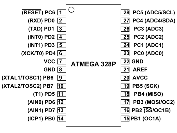 knotty tiger
i guess as long as your 5V loads don't draw too much current that they overload the ICSP programmer's 3.3V output
vast flume
ok
So I should use a schottky diode?
And ig any value is fine as long as its greater than 5v or so?
So like if I just used the same diode as the one used for the regulator? https://www.digikey.com/en/products/detail/MBR130HW/6022882
knotty tiger
yeah, using a Schottky will reduce power and voltage loss. you could use a p-MOSFET wired as a reverse polarity protector, if you want even lower loss, but it adds complexity
vast flume
ok
knotty tiger
vast flume
So like if I just used the same diode as the one used for the regulator? https:/...
yeah, that would probably work. might be somewhat overrated, but keeping your BOM small by not using different diode types might be worth it
are you planning on running your 5V loads off of ICSP power?
vast flume
knotty tiger
are you planning on running your 5V loads off of ICSP power?
I might while programming it
But their current draw is extremely minimal

These incredibly small surface-mount LEDs are an easy way to add a lot of very tiny (but bright!) colorful dots to your project. They are just mind-bogglingly small - 2mm square. ...
Literally just 3 of these lol
Is this the correct configuration for D2?


 fervent lance
does anyone have any data on the bias instability and velocity random walk of the lsm6dso/lsm6dso32
is the accelerometer on that any better than the bmi088?
the noise looks better on the lsm6dso32 but the factor offset is the same, what really tells the story is the data on the random walk and bias instabillity
vast flume
I am trying to program my atmega328p over ICSP from an arduino uno, but I am getting this error
 distant raven
vast flume
I am trying to program my atmega328p over ICSP from an arduino uno, but I am get...
distant raven
vast flume
I am trying to program my atmega328p over ICSP from an arduino uno, but I am get...
Sometimes I have had to just press the reset button
Do you have a reset button?
vast flume
distant raven
Do you have a reset button?
On the arduino or my board?
knotty tiger
vast flume
I am trying to program my atmega328p over ICSP from an arduino uno, but I am get...
you're trying to talk ICSP to your 3.3V 328P from a 5V Uno?
vast flume
knotty tiger
you're trying to talk ICSP to your 3.3V 328P from a 5V Uno?
Oh wait yeah I guess I should bypass the linear regulator 🤣
I bypassed the 5v converter but forgot about the other one
knotty tiger
also, what is your avrdude command line? or are you using the Arduino IDE?
vast flume
I'm using the arduino ide
knotty tiger
what did you select as "programmer"?
vast flume
knotty tiger
what did you select as "programmer"?
"Arduino as ISP"
knotty tiger
i can never remember if that works only for burning bootloaders, or whether it also works for burning sketches
ah, seems like you might have to use the "Sketch -> Upload Using a Programmer" menu item https://docs.arduino.cc/hacking/software/Programmer

How to use the Arduino software with a hardware programmer (eliminating the need for the bootloader and saving program space on the chip).
or were you already doing that?
vast flume
Yeah that was how I did it
knotty tiger
can you cut and paste the entire error output, or at least starting with the avrdude command?
vast flume
knotty tiger
did you try formatting as a code block as shown in <#330410763594498050> ?
I did. Is it ok if I send it as a screenshot?


 knotty tiger
vast flume
I did. Is it ok if I send it as a screenshot?
knotty tiger
vast flume
I did. Is it ok if I send it as a screenshot?
that's a bit hard to read, and missing the actual command (maybe one or two lines earlier). but it seems like it's selecting the arduino programmer protocol, which it probably shouldn't do, if you're using "Upload Using a Programmer" to do the upload
you did burn the "ArduinoISP" sketch onto the Uno, right?
vast flume
knotty tiger
you did burn the "ArduinoISP" sketch onto the Uno, right?
Oh yeah looks like that was what I was missing
Worked this time
Is it possible for me to also use the pins normally used for MISO and MOSI as serial pins?
Or should I use spi?
knotty tiger
do you mean for async serial?
vast flume
I dont know actually
I just wanted to be able to get serial output from the board so I can program it while I wait on the new version to come
knotty tiger
oh, so using the Arduino Serial API? you might be able to use software serial, though i haven't tried it before
vast flume
Ok
Would it interfere with my ability to program it using the headers?
Or is that not something to worry about
knotty tiger
no, the SPI ICSP programming process holds the target chip in reset while it's happening, so your target code isn't running to be able to interfere
vast flume
Ok cool
knotty tiger
though, if you're injecting 5V to the 328P, is that also going onto your 3.3V bus to components that might not be 5V tolerant?
vast flume
Oh wait yeah 🤣 oops
I'm a mess jeez lol
I'm just gonna switch to an esp12f in the next version I think
Bc I have already made a pcb for that chip with usb programming and everything
And I don't wanna go through another dev cycle with this one I want to actually use it
knotty tiger
if you want an AVR with native USB, there's the 32U4…
verbal moss
What's the lowest low profile board-to-board removable connectors that could be used for boards with 2.54mm pitch 1x7 pins (max 5V 1A), like QT PY?
Am making cheap unreliable (despite my best efforts) PCB boards with removable QT PY. Want QT PY to be salvaged/reused for other boards/projects. Need to be able to swap without soldering. Will swap maybe once a year, so connector doesn't need to be designed for daily/frequent use.
Currently looking at:
- jlcpcb/lcsc have 4.68mm high Circular Holes Female Headers https://lcsc.com/product-detail/Female-Headers_XFCN-MF254V-11-03-0743_C2889985.html
- Adafruit have 5mm high Short Female Header https://www.adafruit.com/product/4174
- shurik179 shared link for 3.5mm on AliExpress, https://www.aliexpress.us/item/2251800435894905.html. Currently digging around lcsc for similar that jlcpcb will assemble.
- Flexypins allow board on board action, very low profile! But, they require more space under the board than I have available. Also I wouldn't trust them for more than just short term usage. Great for programming/testing, maybe devices in stable pampered environment.
- Misusing Test Points https://www.mouser.com/ProductDetail/Keystone-Electronics/5021?qs=fP5bVVCrK%2FeNcXCJeuA88Q%3D%3D to create spring socket https://www.youtube.com/watch?v=NYWGXLuyH4M&t=2682s for castellated boards.
Wondering if there's a 2.54 pitch SMD mezzanine connector, or something similar for this situation?


MF254V-11-03-0743 XFCN US$0.0774 - 2.54mm 3A -40℃~+105℃ Straight 1x3P Top 3 1 Circular Holes Straight,P=2.54mm Female Headers ROHS datasheet, price, inventory C2889985

These three Short Female Headers alone are, well, lonely. But pair them with any of our ItsyBitsy boards, and you're in business!These headers are particularly ...

An open hardware iPad Retina display adapter for Thunderbolt and Display Port
https://www.kickstarter.com/projects/1859884318/oscar-the-open-screen-adapter
Treadgaming, gaming while running in a treadmill: http://treadgaming.blogspot.com.au/
A documentary video on the origins of Hewlett Packard https://archive.org/details/HPOrigins
http://engine...
slow plover
verbal moss
What's the lowest low profile board-to-board removable connectors that could be ...
how about a DIP socket split in half?
wicked root
I'm working to plan out a mechanical kb build (modified tractyl manuform) and I'm thinking to use AlGaInP RGY LEDs for layer indication, etc because it will give that kinda retro vibe like when I used to use green monochrome monitors. I'm not aware of any pre-made ICs with RGYs giving them addressable drivers. Could someone lend some guidance on driver ICs options for "DIY pixels"?
wicked root
Maybe I should have searched a bit more. Since I'm looking at sidelighting, the number of channels isn't actually too high. I think the AW9523 might fit the bill. Built-in STEMMAQT connector should improve modularity and each board could support 5xRGYs with all LEDs being controlled in parallel. Cool little board.
worldly schooner
wicked root
I'm working to plan out a mechanical kb build (modified tractyl manuform) and I'...
https://www.adafruit.com/product/1378 is also something you can consider if you want independently controlled LEDs with neopixel-compatible control?

Make your own smart LEDs with the same chip that is used in our NeoPixel strip and pixels. This tiny SOIC-8 is fairly easy to solder and can drive a single common-anode RGB LED or three ...
Assuming you need more channels, anywho.
 frosty geode
So I'm looking at 9DOF IMUs, and the three BNO0x5 units all look tempting, but I'm not sure exactly which I might want. If I want "You pressed the button. That means I am at 0 0 0. Oh I moved I am at [some other spot] now." Which one do I want if accuracy of position (second discrete integral of acceleration) matters?
unreal flax
frosty geode
So I'm looking at 9DOF IMUs, and the three BNO0x5 units all look tempting, but I...
The short answer is that positional accuracy is a very tough thing to get from IMUs alone, because the errors accumulate quite fast when you are doing double integration. You really want some sort of room tracking for that, with fixed reference points, etc.
(Though they will work decently for short, relative motions, like "The user drew an 'O' in the air.")
frosty geode
Fixed reference point is the kicker... I don't really have one. Measuring the movement of a sled over a course of roughly 100'.
Have pondered making some sort of physical marker that the Pi's camera can see and do something with that for distance. Not sure how good the spatial or temporal accuracy would be with that approach.
Once I get access to the gym again I'll be able to pull data samples to a RINEX file from the base station GNSS receiver and get the OPUS calcs on it. Can then use that to feed the sled correction data. But GNSS only provides position solutions every second on the UBblox ZED-F9R rover unit.... haven't found a way to get it to send UBX-NAV-HPPOSECEF more than once a second. Would like higher resolution in the temporal domain, at least 10Hz (if not higher, 100Hz would be great).
glacial gale
how would DMA work on NUMA?
woven bluff
you can use augmented reality to generate reference
but if your camera is moving fast the processor wont be able to keep up
frosty geode
We're talking about as fast as I can drag a sled carrying hundreds of kilograms over fake grass.
woven bluff
if you have walls your can also use TOF
frosty geode
I'm not thinking more than maybe 1-2m / sec
Haven't found a TOF that does 35m ... but... the area I'll be working in as fencing. A TOF sensor aimed at the fence would be able to measure the bars/gaps... that might be useful.
woven bluff
long range TOF requires alignment
frosty geode
Thankfully alignment wouldn't be too difficult. I will have a line to follow, I'll be moving quadrupedally, and a couple hundred kilograms will keep the sled level.
woven bluff
you can also use Doppler radar
frosty geode
Like my path is only like 2 - 3m from the fencing, parallel to the fence. A TOF aimed perpendicular to the direction of movement could use the fence as an odometer source of sorts.
... multiple TOFs, set at distances intentionally NOT the gap to be measured... could get me higher precision. Use a counter-window technique.... ooooooooh.
You're a genius dude. :)
I can use the walls... they just happen to be fences.
With that and the HPPOSECEF and PVAT solutions (especially given the ZED-F9R's real time kinetics), I will be able to get a new reference every couple tenths of a second. Then the various IMUs can give me the temporal resolution between those references.
woven bluff
complicate hardware invites unforeseen problems at implementation
if your arena is not too big, 4 cameras at 4 corners of the arena, AR motion tracking
frosty geode
It's maybe 45m long, probably 10m wide.
woven bluff
frosty geode
With that and the HPPOSECEF and PVAT solutions (especially given the ZED-F9R's r...
ADR also needs vehicle input, like wheel revolution
frosty geode
But that requires me figuring out a lot more complicated data since it requires image processing. Like how do you even find the CYMK painted ball in all four images?
unfortunately, no wheels, sled is entirely internally static. Though I suppose could give it a wheel without too much hassle, could just hang off the side and lightly rest on the ground.
woven bluff
train a model to recognize you pulling a sled
frosty geode
... I am a fudging idiot.
a gosh darn wheel hanging off the side with a patterned wall and a line beam distance. Count gaps.
AI is absolutely overkill for this project, I wouldn't even entertain that thought.
The wheel though is a good point. Good catch on that one.
woven bluff
any kind of encoder will do
if the floor have patterns, you can even cut some slits on the sled
frosty geode
It does, but they're far too spaced to get the spatial resolutions I need.
THOUGH... again. A potential source for references with IMUs providing the inbetween.
thinks So wheel rotation counter, ground tracking, fence tracking, ... that should get me to 0.25m for references. Possibly even tighter. Especially that wheel.... ... yeah that should get me easily to the sorta spatial and temporal resolutions desired.
Now if I could get the NAU7802 to output at a higher rate... . >.<
If I make the length of the sled slightly larger than the spacing of the lines on the track... and do the same thing with the ground sensor I am thinking of doing with the TOF aimed at the fence and a much shorter distance sensor to the wheel (or just bright/dark sensor at that rate).... yeaaaaah, I think I can cull enough data to get frequent enough references to trust the IMUs to fill in the rest.
kinda locks me to that location though. BUT for training that's a fine assumption. Gives me time to ponder how to better resolve the issue in the field when I'm measuring against an actual plow.
Thanks, good catch on the wheel and fruitful soundboarding. I appreciate the time and the access to your brain power. :)
O.O A SPOOL OF ROPE. Holy crap, the wheel thing again. Stake in ground. Rope to stake... but rope passing through a channel with a wheel that presses against the rope. Move sled/plow, rope plays out, rope turns wheel, measure wheel movement.
That would let me get my distance as frequently as I can narrow the gaps in the wheel a TOF sensor measures. Puts everything on the sled/plow and isn't location specific... long as I can secure the rope SOMEWHERE (and it's long enough to reach the tie-down and go the full length), it would work.
PERFECT
knotty tiger
frosty geode
O.O A SPOOL OF ROPE. Holy crap, the wheel thing again. Stake in ground. Rope...
that's very similar to the origin story of the word "knot" for "nautical miles per hour" 😂
frosty geode
knotty tiger
that's very similar to the origin story of the word "knot" for "nautical miles p...
Good solutions generally pop up repeatedly. :)
... that face when you're watching Ladyada describe the BNO055, talk about confusion between Euler and quaternions, and you're going, "Why would I be confused about those, I have a Second Life..."
facedesks
limpid nest
What is the distinction between a Step/Direction driver and a normal stepper motor driver. I am evaluating a board for a friend that has this (https://www.trinamic.com/fileadmin/assets/Products/ICs_Documents/TMC4210_datasheet_rev1.07.pdf) with outputs into this, which is connected to the motor. https://www.trinamic.com/fileadmin/assets/Products/ICs_Documents/TMC2209_Datasheet_V103.pdf
unreal flax
It looks like the first one is a motion-control chip, so it turns high-level goals like "move to this position" or "accelerate to this velocity" into the low-level steps that the motor should take. And then the second chip takes those low-level step signals and actually drives the motor coils with enough current to make them happen, including handling microstepping if needed.
 candid orchid
Does it matter if i use internal or external pull-ups on buttons? On STM32
distant raven
candid orchid
Does it matter if i use internal or external pull-ups on buttons? On STM32
External pull-ups are usually preferred though internal would probably work
worldly schooner
Just be careful not to use both in opposite directions, unless you like funky voltages and wasted power.
limpid nest
Yeah an external sets what your pull direction can be
candid orchid
Should a piezo buzzer have a parallel resistor or diode?
knotty tiger
is it a bare transducer, or does it have a driver/amplifier built in?
candid orchid
Simple transducer. One of those cheap ones you get from chinese arduino kits
 merry grail
So I accidently ordered a 27.12mhz crystal for my rp2040 project. I only discovered it while review the datasheet hoping to learn more about load capacitance and ESR. I just feel like I needed to admit my mistake in a place where my judgment can be fairly determined.
limpid nest
It happens!
worldly schooner
Judgement? For a crystal? Worse mistakes have been made and recovered from. At least you didn’t place it and tear all of your hair out after it behaves weirdly.
merry grail
Um... well I did spend hours trying to figure out why it would boot correctly. My first PCB, I thought I might have routed the data lines with too much interference. Fortunately, I've previous removed my hair for occasions just like this, to save time.
distant raven
My best mistake was ordering the wrong size crystal for a project
In terms of crystal mistakes
merry grail
I am curious if there is a way to use just one button to enter bootsel, resetting would be accomplished by power cycle. The goal would be to reduce the number of components.
distant raven
merry grail
I am curious if there is a way to use just one button to enter bootsel, resettin...
The Pico does this exactly
merry grail
Oh, I guess that's one I didn't look too closely at. Most of them use both. I'll just figure out how they did that, thanks!
Correct me if I'm wrong but would you need to hold bootsel while power cycling on the pico?
distant raven
Yep
merry grail
I guess what I'm looking for is a way to trigger a bootsel/reset with one button press (w/o power cycle). Thoughts?
knotty tiger
candid orchid
Simple transducer. One of those cheap ones you get from chinese arduino kits
yeah, those can be tricky. at the very least, you might want to have a a series resistor and a flyback diode, which might need to be a zener diode, because a piezo transducer could generate very high voltage peaks in both directions due to resonances
 broken zenith
Does anyone have experience with JLCPCB's "Global Parts Sourcing"? Specifically, I want to order parts from DigiKey and have them assembled on my board. Not really sure how to specify which part goes where, or even if that's done in KiCad or on the order form of JLCPCB. Feel free to ping me. Thanks
I'm also open to other providers if they can compete with JLCPCB's pricing for a 70x70mm board with 4 layers
hushed smelt
@broken zenith If you're using KiCad instead of what they want you to use which is EasyEDA then your BOM has to be perfect to their format. Once you submit a board you can ask to have it reviewed and if there are any part descrepencies they'll email you. You must select the "board review" option or whatever they call it while ordering the PCB.
The bad part about using digikey parts is they'll have to order them from Digikey (North Dakota) and have them shipped to China extending the amount of time you'll get your board probably to about 2 months.
If you can find the same part # with LCSC (which is like pulling teeth inspecting datasheets sometimes) you'll be much better off in terms of footprint matching and turn around.
To do that you have to look up the manufacturers part #, not digikeys part #, then search LCSC for the same manufacturer part, inspect the datasheet to make sure it's the same, and insert that into your BOM. Your question is heavily related to BOM which is the boring part of a project but if you get it wrong, you're going to be angry about it. Maybe post up what you've got of your BOM and someone can take a look for you.
How is your haptic fidget spinner project going? Hope it's going well. I thought that was a really neat project. 🙂
broken zenith
Thanks so much @hushed smelt! This is actually for the E-Fidget. It's going alright, but I want to take manual assembly out of the equation. Correct me if I'm wrong, but what you're saying is to specify the LCSC part numbers in the BOM that correspond to the DigiKey part? You're right, at that point there's no benefit to using DigiKey over LCSC, and it adds a lot of complication. Do you know of any other providers that would make this easier?
Thanks
It looks like PCBGOGO is an option
hushed smelt
@broken zenith use a US based pcb fab house like OSHPark but you're not going to get the cheap chinese prices
Digikey... also fabricates PCB's so there's that. I'm sure if you email them they'd be happy to work directly with you.
They have an online design tool too which is a similar setup to LCSC & JLPCB partnership except Digikey does it all in house under 1 company. If you're already used to KiCad I'm sure they can work with that too as KiCad is a major design software.
All PCB manufacturers in the US are like 3-4x more expensive than china, so be prepared for sticker shock if you've been spoiled by china's bargain basement prices.
vast flume
Is it a bad idea to have a lipo more or less resting on the underside of a pcb?
I have really tight space constraints and everything has to fit within this enclosure. The box on the right underneath the pcb represents the volume occupied by the lipo and its cable, with some additional space to make sure it doesn't get squished


The enclosure is 58mm x 38mm x 21mm
 fast tundra
it's probably fine as long as nothing above it generates a lot of heat or is sensitive to heat.
I'd avoid through hole components in that area as well
verbal moss
Another LED board project, my 1st attempt failed, working on 2nd... Does this BSS138 based logic level shifter schematic and layout look okay to you? Trying to boost data signal from QTPY ESP32 to first WS2812B RGB LED. My 1st custom PCB design, so any feedback/suggestions are appreciated. Cheers!
Currently using https://lcsc.com/product-detail/MOSFETs_MCC-Micro-Commercial-Components-BSS138AKDW-TP_C779245.html. Came up with my schematic based on info mostly from Adafruit learning docs, https://www.digikey.com/en/blog/logic-level-shifting-basics, and this channel.
Can just about visualize ~3V3 data signal on my cheapo DSO138 scope, but am unable to visualize boosted ~5V signal with enough clarity to inspire confidence that the level shifter fragment of the circuit is good enough for 'neopixel' frequencies . Not sure if scope and/or BSS138 and/or me are the issue. I did temporarily hack code to set pin constantly high, this helped verify ~3v is boosted to ~5V. However, am seeing misc interweb info saying BSS138 are only good up to 2mhz(?). Currently using 10K pull-up, anyone think lower value e.g. 2.2K would be better and help with working well at the 800khz that WS2812B use?
My 1st batch of boards don't work for various reasons. Used WorldSemi WS2812B-mini 3535 RGB, the LEDs fail in various spots. Would use SK2812 (seem to be more reliable?) but no stock for size I want. Found and fixed several problems as I work on 2nd attempt, for example:
- Made larger traces
- Larger clearances for traces and copper fills, so less antenna GND copper fill in tiny nooks.
- Removed VIAs under LEDs, my attempt at thermal management.
- Made board larger so parts not so close to the edge. In addition to my design issues, am concerned LEDs are being damaged during jlcpcb SMT assembly.
- Increasingly leaning towards using 5050, feels like assembly will be easier and more reliable.
Thanks for reading, articulating a problem can be cathartic if nothing else 🙂


BSS138AKDW-TP MCC(Micro Commercial Components) US$0.0848 - 50V 220mA 1.9Ω@10V,500mA 350mW 1V@250uA 2.9pF@25V 2 N-Channel 22.8pF@25V -55℃~+150℃@(Tj) SOT-363 MOSFETs ROHS datasheet, price, inventory C779245
 rustic linden
So I'm making a filament bulb based thing, and I'm planning on using 74HC164 chips to drive the panels I've got, and I'm just wondering, since a single bulb uses about 0.1A at 5V (0.08 at 3.3V), would I need to use transistors to power them? and can i use a higher voltage on the flat side (i forget what it's called) than the side where i need switching?
spice turtle
rustic linden
So I'm making a filament bulb based thing, and I'm planning on using 74HC164 chi...
Ironic because Im buying up LED filaments in R,G, and B, lol :). I would use transistors. If you are using a high voltage, say 12V, then you definitely need transistors. Generally, you also want your cathode at 0V, and your anode can be higher. I hope thats what you mean.
Unless you mean the collector side of a transistor, then yes, you can use a higher voltage
Im using FETs in this example
 vast flume
Do I have to stay at a 0.63mm grid size for routing or am I allowed to go lower?
Also for signal traces can I go smaller than 0.25mm?
slow plover
depends on the board manufacturer
generally the rule of thumb is 6 mil (0.006 in) min trace width and min spacing between traces, but it will depend on the manufacturing capabilities of the fab
worldly schooner
vast flume
Also for signal traces can I go smaller than 0.25mm?
Worth noting too, if your traces get thinner, your trace resistance will increase as well, possibly reducing power efficiency and affecting a number of other circuit parameters.
vast flume
ok
verbal moss
I regret using 0.254mm everywhere for my 1st PCB attempt (EasyEDA, jlcpcb for Fab and Assembly). Got the super cheap 1oz boards, and I should have had more reasonable expectations. Noticed NeoPixel rings have 0.305mm data signal traces, and 0.610mm for power, but not sure if Adafruit use 1oz or thicker boards? Also I'm guessing different manufacturers have different cost saving interpretations of '1oz'.
Doubling trace width, or more even, for my 2nd attempt.
verbal moss
verbal moss
What's the lowest low profile board-to-board removable connectors that could be ...
Recently realized the following female headers (I recently mentioned) require specific machined male "Swiss Pins". The regular stamped-metal square dupont pins won't fit.
- jlcpcb/lcsc have 4.68mm high Circular Holes Female Headers https://lcsc.com/product-detail/Female-Headers_XFCN-MF254V-11-03-0743_C2889985.html
Swiss Female Header https://www.adafruit.com/product/3646
Swiss Male Pins/Plug https://www.adafruit.com/product/3647
https://www.youtube.com/watch?v=qTf2UP2Q2E4
MF254V-11-03-0743 XFCN US$0.0774 - 2.54mm 3A -40℃~+105℃ Straight 1x3P Top 3 1 Circular Holes Straight,P=2.54mm Female Headers ROHS datasheet, price, inventory C2889985

Get a precision fit with these lovely machined 'Swiss pin' headers. In this world, nothing can be said to be certain, except we need headers, headers, and more headers!Each pack ...

Get a precision fit with these lovely machined 'Swiss pin' headers. In this world, nothing can be said to be certain, except we need headers, headers, and more headers!Each pack ...
Browse the finest in headers at Adafruit:
https://www.adafruit.com/product/3646
A small part that makes a big difference - consider the often overlooked machine pin header socket #adafruit #collinslabnotes
Visit the Adafruit shop online - http://www.adafruit.com
LIVE CHAT IS HERE! http://adafru.it/dis...
supple pollen
verbal moss
Recently realized the following female headers (I recently mentioned) require sp...
There are a few other possibilities. There are some nice stamped pins that are the same basic dimensions as IC pins (I think they're called "flip pins")
verbal moss
supple pollen
There are a few other possibilities. There are some nice stamped pins that are ...
Thanks @supple pollen, didn't know about these before. Nice!
Flip-Pins == Pins { dimensions = DIP IC pins, can solder to PCBs, won't damage breadboard }
vast flume
Hey guys, just to be sure, is this the correct orientation to have in order for the USB port to face to the right?
 distant raven
vast flume
Hey guys, just to be sure, is this the correct orientation to have in order for ...
distant raven
vast flume
Hey guys, just to be sure, is this the correct orientation to have in order for ...
Seems like it’s oriented right
vast flume
Ok thx
distant raven
vast flume
Ok thx
Just double check the DP/DM pins
vast flume
distant raven
Just double check the DP/DM pins
Do they look like they're in the wrong order? I got this footprint from snapeda
distant raven
Seems okay, I just recommend double checking because it’s a common thing to mess up
low anchor
Hey so I had a circuit board I designed, and it worked fine for the first few times I tested it, but then I plugged it in to the power supply again and one of the chips burned up. I'm not sure why; I measured the voltages and everything seemed normal after it finished burning. So I want to put fuses on each chip to make sure they can't draw too much power, and I realized my design had some data lines right next to higher voltage lines which was probably related. Any other things I should double check? What kind of fuses should I look for? We're talking like 12v and under
distant raven
low anchor
Hey so I had a circuit board I designed, and it worked fine for the first few ti...
PTC fuses should be good enough, do you know the current load you’re using?
Also, what chip fried if I may ask?
 unique patio
low anchor
Hey so I had a circuit board I designed, and it worked fine for the first few ti...
unique patio
low anchor
Hey so I had a circuit board I designed, and it worked fine for the first few ti...
It would be worth checking the design carefully, rather than just adding fuses. Sometimes power-up issues can be due to a sequencing issue: power is coming up on one part of the board before another. For instance, if the CP2104 power pins come up in a certain (bad) order, the chip internal power circuitry can lock up and overheat.
low anchor
That makes sense. Here's my design files; it was the I2C IO expander that burned up. The other two chips on that I2C bus (the MAX11612 via a logic level converter, and the ESP32) were fine and were able to communicate afterwards. (not sure about during since it was only a few seconds.)


I think the issue was caused by me routing a power line through the 3x2 header, mid right, in my over-zealousness of avoiding vias. (I was going to make it on my university's PCB mill so I couldn't use vias)
knotty tiger
low anchor
I think the issue was caused by me routing a power line through the 3x2 header, ...
so you're thinking that a solder bridge happened and shorted power to the trace you routed between pins of the 3x2 header? i assume the PCB mill also doesn't do solder masks, right?
low anchor
No, I ended up ordering it online, so I did have a mask. And it worked correctly the first time I connected it - because I connected the power supply to the board, and then the PSU to the wall, I think. When it lit up I think it was caused by the fact that I hooked the power supply to the wall, and then the leads to the board - which created a spark, and I think that spark is what crossed the gap. (It's a 4 amp 12 volt power supply)