#help-with-hw-design
1 messages · Page 3 of 1
 heavy jasper
 vast flume
Oh no 🤣
 distant raven
They look cool when they pop
vast flume
Hopefully mine wont 🤣
distant raven
A nice little plasma ball
vast flume
In case any of you wanted some more info about my plans for this flight computer:

(The renderings shown are the old version from before I switched to having usb on the board, it looks a lot more crowded now)
distant raven
vast flume
(The renderings shown are the old version from before I switched to having usb o...
Just wait till you make a board like this:

 knotty tiger
nice! i like the graphic design
distant raven
Bodge wiring mileage may vary
vast flume
distant raven
Just wait till you make a board like this:
Jeez 🤣
distant raven
65 parts lol
knotty tiger
distant raven
Bodge wiring mileage may vary
is that 30AWG wire-wrap wire?
knotty tiger
distant raven
Yeah
heh i swear i've used that wire more often for high-density solder prototyping than for actual wire wrapping
vast flume
How do you even go about figuring out part placement for something that crowded
knotty tiger
run the autorouter and then yell at it a lot while undoing its mistakes?
vast flume
🤣
distant raven
By how close parts needs to be to the ICs lol
vast flume
True
heavy jasper
Stones then pebbles - big chips first, little parts around them.
vast flume
I see
distant raven
I do fixes placement, ICs, the passives/LEDs
vast flume
Ah
distant raven
Fixed placement in this case being USB, battery connector, and headers. Though I made a feather template to only have to worry about usb and battery connector
vast flume
Actually I do have a quick question about smd leds
I have a smd ws2812b nano on my pcb
But I didn't realize how physically small they were until mine arrived from amazon 🤣
How bright are these?
distant raven
Regular SMD LEDs are usually a few hundred to maybe 1K mcd which is mini-candela
vast flume
And approx. how many mcd would a full size ws2812b be?
distant raven
Which depending on the viewing angle, could be 0.1 lumen to maybe 10 lumen tops
WS2812b can get very bright. A few tens of lumens
So probably 3-4 LEDs with the same viewing angle
vast flume
Ah ok
distant raven
 vast flume
Oh thats not bad
distant raven
The RGB led on my fpga board here is very bright
That’s just green too
This video shows the brightness of it at various stages of illumination
vast flume
Oh so you have the same led
Nice I think I should be good for now
I'll prob swap it out for a full sized one in the next batch
vast flume
Oh its a multicolor?
knotty tiger
i find even the smaller NeoPixels to be painfully bright, personally
distant raven
That RGB led sinks right to RGB pins of the FPGA
vast flume
I see
distant raven
24mA per channel, though it will only sink as much as the LED will draw
 hushed smelt
They’re painfully bright because there’s no diffuser.
distant raven
These LEDs 🤓
And very cheap
$54 and you can get 1000 lol
But they’re super nice
hushed smelt
0404 is pretty small. Is that the same one Adafruit uses on feathers because even the tiny ones hurt my eyes.
 hushed smelt
Good lord
distant raven
Lol
hushed smelt
And the pads are like right next to each other too.
knotty tiger
like you can sneeze and lose a dozen of them across the room
hushed smelt
They couldn’t be nice and put the pads on the edges?
distant raven
Thankfully haven’t lost one yet
hushed smelt
Have you actually successfully flowed one yet?
distant raven
Yeah
hushed smelt
Geeez. Beyond my ability.
 hushed smelt
That’s a little easier though more surface area contact.
In a straight line and not smd.
 hushed smelt
I haven’t tried Uson8 yet. I’m scared of killing my only Bluefruit sense.
distant raven
Bodging is not my best skill set so the fact I succeeded surprised me
knotty tiger
distant raven
Bodging is not my best skill set so the fact I succeeded surprised me
did you do the soldering under a dissecting scope?
hushed smelt
Are you using a camera, microscope, or diopter?
distant raven
I used a… magnifying lamp lol
hushed smelt
Impressive.
distant raven
Thanks, I’m impressed too. I did verify under my electronic microscope
knotty tiger
right-light magnifiers are possibly underrated?
distant raven
Mayhaps
hushed smelt
I had a nice diopter with a huge glass lense. Base broke and threw it out when I moved. Since tried to find a replacement but everything on Amazon is garbage with a 5x plexiglass looking lens
distant raven
Mine is like a flexible neck, light ring, and I’m guessing a plexus glass lens
hushed smelt
Wish I’d kept it and found a way to repair the base. Didn’t realize it would be difficult finding a suitable replacement. If you have any suggestions I’m all ears.
Adafruit doesn’t have anything like that. I did get one of the small usb magnifiers, it is awful.
distant raven
I bought a $80 cheap electronic microscope from Amazon, protege same ones for $60 on Aliexpress
hushed smelt
Hmm maybe I could use a high quality webcam and put a magnifying lens on it somehow.
distant raven
Elikliv EDM9 7'' LCD Digital Microscope 1200X, 1080P Coin Microscope with 12MP Camera Sensor, Wired Remote, 10 LED Lights, Soldering Electronic Microscope for Adult, Compatible with Windows/Mac OS https://a.co/d/erJApiK

Elikliv 7'' LCD Digital Microscope 1200X, 1080P USB Coin Microscope with 12MP Camera Sensor, Wired Remote, 10 LED Lights, PC-Microscope View for Adult Kids, Compatible with Windows/Mac OS
This is what I got
Works well enough
I don’t know if I trust it enough to plug into my computer but it works for what I need it to do.
 granite steppe
Hello all, I'm trying to add Qt-Py ESP32-S2 in my hardware design.
In it's pinout section, it's mentioned how to power it from external source (mine is 5.17V power source), but I would also like to connect the USB to the QT-Py and not affect the external power source.
So adding a reverse schottky diode won't be enough, using a PMOS + schottky diode combo as power selector seems another option, but without access to direct VBUS (either as pin or as Pad on Qt-Py), how can I detect if VBUS is present?

 distant raven
granite steppe
Hello all, I'm trying to add Qt-Py ESP32-S2 in my hardware design.
In it's pino...
distant raven
granite steppe
Hello all, I'm trying to add Qt-Py ESP32-S2 in my hardware design.
In it's pino...
Great question, I actually discussed a solution you can use that works with the Qt Py and feathers. You will just need a 3.3V regulator and a p channel mosfet.
Vusb goes to the mosfet gate, and the mosfet sits along the 3.3V line from your external regulator
Essentially what happens is what vusb is 0V, it turns on the mosfet. What vusb is on, it turns it off
As long as you provide a regulated 3.3V to the 3.3V pin, it will work just the same.
granite steppe
So bypass the onboard LDO and use one of my own?
distant raven
Yes
Or you can use a schoolyard diode On your external voltage input to 5V like the learn guide suggested
I don’t really like that approach personally but it’s easy and valid
granite steppe
distant raven
Or you can use a schoolyard diode On your external voltage input to 5V like the ...
That was the initial plan, but I don't like it. The +5V line from the above image then gets power from two sources, I won't want to heat up the LDO which it feeds in to.
distant raven
The voltages would be in parallel so it would be ~5V either way going into the ldo
granite steppe
distant raven
The voltages would be in parallel so it would be ~5V either way going into the l...
It is cheap though, the BOM is already over 120 components.
Would you say a reverse schottky like D10 here would affect my VDD power line if Qt-PY is powered from USB?
 distant raven
Schottky diode will block any reverse voltage/current into VDD from the Qt py when it’s powered over it’s USB port
granite steppe
At this moment it will be good enough for me.
distant raven
Yeah, it just depends on how complex or “safe” you want to make your voltage lines. I personally opt for more complexity because sometimes it can save hassle or headache. But the easy way in this case is easily valid and likely just as good an option. Cheaper too.
granite steppe
What are the cons of using Schottky here other than the obvious power loss?
distant raven
granite steppe
What are the cons of using Schottky here other than the obvious power loss?
No “off” would be a con in my book
 dry bough
i think a mosfet ideal diode would be interesting
dry bough
granite steppe
What are the cons of using Schottky here other than the obvious power loss?
by the way, power loss is commonly referred to as "forward voltage drop". i hate correcting people but i hope you don't get confused by voltage drop/power loss
 supple pollen
Power is voltage drop times current, so it's all related.
 elder peak
That's watt I'm talking about!
 pale umbra
I don't understand either what they mean by using the 5v pin as voltage input
distant raven
pale umbra
I don't understand either what they mean by using the 5v pin as voltage input
Applying an external voltage source to a qt py, it’s recommended to hook it up to the 5V pin
pale umbra
ok 😦 I guess I'll need a diode then 😦
wanted to use batteries to power the whole qt py and power a 5V LCD from the 5V pin 😦
 onyx canopy
Which Qt Py do you have? I have the ESP32-C3 and it has battery pads that already have the diode
pale umbra
esp32-s2
onyx canopy
Same. Have a look here: https://learn.adafruit.com/adafruit-qt-py-esp32-s2/pinouts

Adafruit Learning System
The cutest ESP32-S2!
pale umbra
I've seen this several time but I can't tell if I can do what I have in mind because I don't understand it
onyx canopy
As far as I understand (but I’m not an expert!) you have two options. Use the battery to power both the lcd and the qt py (via the 5V pin). The diode is needed to prevent current flowing into then battery.
Use the battery pads and then connect the LCD to the 5V pin
pale umbra
but isn't current already flowing into the battery from itself? why is that a problem ?
onyx canopy
As far I understand you want the current to flow from the battery to the qt py but not in the other direction, which would “charge” the battery in an unsafe way.
Again, not an expert and I might be wrong
pale umbra
it's ok if there is 2A and -2A it will just cancel up and safely dissipate 😄
That is what annoys me about electronics, seems like with little experience it's O(n!) sometimes where n is the number of electronic components
onyx canopy
Something I am not sure about is with the diode it is safe to plug in the USB-C (for flashing a new version of the software) while leaving the battery plugged in
 hushed blade
You want the diode. Any amount of reverse current is bad for a battery, and even if your two power supplies are conceptually both 5V, they won't be perfectly 5V, either one could be slightly higher or lower.
In general, there is a reason for the recommendations, and batteries are one of the few places where things can get very dangerous with low-voltage DC, you want to respect batteries
 limpid nest
onyx canopy
As far I understand you want the current to flow from the battery to the qt py b...
limpid nest
onyx canopy
As far I understand you want the current to flow from the battery to the qt py b...
You're correct
pale umbra
but diodes just limit current right? they can't block it ?
limpid nest
Reverse biased they do a pretty remarkable job at blocking it.
knotty tiger
it depends on what you mean by "limiting current". diodes don't really limit current the way that some active current limiting circuits do (hard cutoff or foldback)
hushed blade
I think Emporer is using current when they mean voltage in at least some cases
there are different types of diodes, but in general diodes block any reverse voltage and let voltage through the "proper" direction (with a drop)
pale umbra
When you just got a 15$ sensor but adafruit has something better at 1/2 of the price 😢
vast flume
Hey guys, quick question
I noticed that this pcb doesn't have component labels on the silkscreen

Is it not required to add them?
(Assuming it is being assembled by jlcpcb)
distant raven
vast flume
I noticed that this pcb doesn't have component labels on the silkscreen
You can add them if you want to, but it’s not required
 unreal flax
Board assembly is typically automated, so it goes by part-coordinate files that you submit with your board, rather than humans looking at the labels.
hushed blade
you will eventually be annoyed with yourself if you leave them off -- you WILL eventually want to use a multimeter or rework something -- but if the aesthetics are more important than that convenience to you, go ahead
I would probably only leave them off if the board had some sort of art on it or was really designed to be looked at. The pictured one wouldn't cross that threshold for me, but no hate to whoever made that board
supple pollen
I used to put part designators (like R1, C1, etc.) but later found if I had room for only a designator or value, the value was more useful since I hand-assemble my boards. For debugging, I can look up the designators by position if need be. One possibility is to put the value under the part (so you can see it while you're assembling it) and the designator beside it (so you can see it when debugging).
hushed blade
The value tends to take more room, but that's a good choice, too. >50% of the time what you want when you are looking at a board on that level is the value to assemble. The designators mostly are handy when discussing with another person, doesn't come up that much for a single developer
limpid nest
I like designator because there isn't enough room for all the other things besides value that may be relevant
vast flume
Thanks for the feedback
I think I'll keep the designators on the silkscreen while in development, and remove them on any production runs I do afterwards
pale umbra
I don't even know why adafruit and other sellers usually leave them on
not like I'm going to replace them with 1% 5W gold premium ones as a "mod" anyway...
 somber marsh
My current project is a keyboard with some rotary encoders. I have a 10x7 button matrix wired to a feather board (RP2040). The feather has 21 accessible GPIO, I'm also using 2 for I2C and one to drive neopixels. I want to add a rotary encoder to the keyboard. Rotary encoders need two pins. Is it possible (or even a good idea) to wire and access the rotary encoder into the matrix in place of a switch? I'm using the circuitpython keypad library if that makes a difference.
distant raven
somber marsh
My current project is a keyboard with some rotary encoders. I have a 10x7 button...
Maybe look at these: https://www.adafruit.com/product/4991
Rotary encoders are soooo much fun! Twist em this way, then twist them that way. Unlike potentiometers, they go all the way around and often have little detents for tactile feedback. But, if ...
Feather RP2040 should have a Stemma connector
And it’s i2c so it can also use the same i2c bus you’re already using
somber marsh
Seen those. They don't quite work where I want this rotary encoder. its in a tight space between keys. The space available between keys is a square, 19.05 mm on each side. This product is about 25mmx25mm, unfortunately. Maybe a very small IO expander would work (number of pins, I'm sure I could find some physical space for it.) It's also just (possibly) unnecessary complexity and cost. Thanks for the help!
distant raven
Ah gotcha
vast flume
Any tips for hot air reflow soldering a 12-VFLGA package?
How will I know when its done & if any of the pads bridged?
distant raven
vast flume
How will I know when its done & if any of the pads bridged?
Do you have an electronic microscope
Sometimes if there is enough space around the chip you can look under it and inspect
hushed smelt
a proper reflow depend on heating profiles and trying to adhere to them best you can. some smd packages provide the reflow tolerances and profiles, some don't.
most hobbyists try to get it close and cross their fingers 🤞
even a toaster oven can be used on a professional level. adafruit literally started out making thousands of boards with a single toaster oven.
like anything else it takes practice
vast flume
distant raven
Do you have an electronic microscope
No I dont. Just have a hot air rework station
Its also gonna be the second time I've ever reflowed something 😅
Practiced today on a old motor driver pcb but it only had larger packages where the pins were on the outside
distant raven
Yeah, BGA is a bit tough
vast flume
I'm scared, this is gonna be interesting lmao 🤣
Luckily I bought a bunch of extra components so I can mess up a bunch of times
supple pollen
vast flume
How will I know when its done & if any of the pads bridged?
A continuity measurement can show bridged pins
vast flume
supple pollen
A continuity measurement can show bridged pins
Good point
vast flume
Decided to make a reflow hotplate. The heating element I'm using draws a max of 5A at 12V. Would this smd mosfet be ok to use? https://www.digikey.com/en/products/detail/onsemi/RFD14N05SM9A/1849935?utm_adgroup=Discrete Semiconductor Products&utm_source=google&utm_medium=cpc&utm_campaign=Shopping_Supplier_onsemi&utm_term=&utm_content=Discrete Semiconductor Products&gclid=CjwKCAjwpKyYBhB7EiwAU2Hn2cVkC9RKE_aKMFYsNUkZMH0K9jHoZCeriRM_YsU6zdPbKKLisg1xLhoC7cQQAvD_BwE
Says the drain to source voltage is 50v and continuous drain current is 14amp but just wanted to be sure
unreal flax
vast flume
Decided to make a reflow hotplate. The heating element I'm using draws a max of ...
How are you driving it? It looks like it won't fully turn on until a gate voltage of around 10V.
vast flume
unreal flax
How are you driving it? It looks like it won't fully turn on until a gate voltag...
Oh wow, didn't realize that. I'm planning on driving the mosfet from an esp-12
supple pollen
You'd need a driver board and the voltage for it. With appropriate drive voltage, that MOSFET is around 100mΩ, so would be dissipating about 2.5 watts. That would need some heatsinking.
vast flume
Should I use a THT mosfet instead?
Oh wait yeah couldn't I combine a THT mosfet with a transistor so the transistor can switch low-current 12v and be controlled by my microcontrollers 3.3v, and then in turn switch the mosfet?
This mosfet for example https://www.digikey.com/en/products/detail/ixys/IXFP5N100P/2116946
supple pollen
Yes, you can build a transistor based gate driver circuit. THT is often easier to heatsink, but it is possible to headsink SMT with sufficiently large copper area and plenty of via stitching.
supple pollen
vast flume
This mosfet for example https://www.digikey.com/en/products/detail/ixys/IXFP5N10...
That 1000V MOSFET is likely not your best choice.
vast flume
supple pollen
That 1000V MOSFET is likely not your best choice.
Interesting. What downsides would using it have?
supple pollen
Usually it will have more resistance and need higher gate drive to work than a lower voltage MOSFET.
More resistance = more loss = more heat to dissipate
vast flume
Higher gate drive as in it would drive more current?
supple pollen
No, it may require both higher gate voltage to turn on fully, and have more gate capacitance to charge/discharge
vast flume
The one I sent says the drive voltage is 10v
But yeah at the same time I calculated 70w of power dissipation...
Wait no my math was completely wrong
It should actually be 1.9w
Would this one work better if I controlled it with a transistor?
 inland jungle
You can use an optocoupler with a transistor output to drive a mosfet
vast flume
Ok I did a bit more research into mosfets, and it looks like this one should be controllable from the 3.3v pin on my microcontroller https://www.digikey.com/en/products/detail/vishay-siliconix/SI2333DDS-T1-BE3/16397455
The Rds_on at 3.3v is only ~0.025ohm; so at a 5amp load that would only be 0.625w of power dissipated. Am I reading this correctly 😅
unreal flax
You previously were considering an N-channel FET, and this is a P-channel one, so if you're switching 12V, that could be a problem with a logic-level input.
supple pollen
The specs you quote sound good but I'm on my phone and can't double check the listing
Oh, yeah, you'd still need a level shifter for a P-channel unit but there should be comparable or better N-channel units available since it's easier to build high performance N-channel FETs
vast flume
This one looks like a N channel mosfet with comparable specs
rds_on of 0.024 at 3.3v
hushed blade
mosfets that are driven by 3.3V are annoyingly hard to find, unfortunately.
 void sentinel
I am trying to make a thingy. #show-and-tell message
I am wondering who to use for pcb fabrication?
That link is not very informative. Should I delete and repost here?
The only design checks that I approved are dimension errors on the usb micro I used from the Adafruit's M0 proto board.
supple pollen
There are lots of choices for PCB fab
void sentinel
That is why I am asking. Have you ever made one? who did you use? what have you heard? what am I doing wrong? lol
 tough matrix
how many boards do you need? how quickly do you need it?
for small boards or when speed is crucial, Oshpark is a great choice
for anything else, I normally use jlcpcb
tough matrix
As for board review, can you post PDFs rather than screenshots? it would be easier to read.
Two first questions:
- did you run DRC?
- how will you program the SAMD21? usually it is done using an SWD programmer, but then you need to provide a header (or test points) on the board for connecting it
 granite steppe
vast flume
Is this the correct configuration for a pulldown resistor on an output pin?
granite steppe
vast flume
Is this the correct configuration for a pulldown resistor on an output pin?
Yes, as long as the impedance of the logic on D6 is much smaller than 10kΩ, this should work. Your schematic design needs some cosmetic work though, but that's not important. Make sure on the first part and 10kΩ is usually a good pull down value.
vast flume
@granite steppe D6 is going to the gate of a mosfet ic. Does that change anything?
I read about sometimes wanting to use a "soft" pulldown on gpio outputs, but couldn't find any values for what that could be
knotty tiger
vast flume
<@663905668285202452> D6 is going to the gate of a mosfet ic. Does that change a...
what is the goal of using R11? is it to discharge the MOSFET gate? ESD protection? etc?
granite steppe
A P-channel or N-channel Mos? Is the gate connected to anything else? What's the Vgs of the MOSFET? What's the resistor used for, gate discharge?
knotty tiger
hm, yeah for n-channel, i think driving the gate actively low for turn-off might be preferred, if the GPIO can sink enough current?
granite steppe
knotty tiger
hm, yeah for n-channel, i think driving the gate actively low for turn-off might...
Yes, and for p-channel switch, if the gate is pulled to source(hopefully not directly but through a 100kΩ+ resistor), pull down won't have enough effect, so its useless there.
 woven bluff
is there a LCD that can be mount directly on top of Feather doubler or tripler ?
knotty tiger
woven bluff
is there a LCD that can be mount directly on top of Feather doubler or tripler ?
what kind of LCD? TFT? character? low-res graphical?
woven bluff
doesn't matter
from the size of Feather doubler or tripler , it cannot be alphanumeric
knotty tiger
can you elaborate by what you mean by "mount directly on top of a Feather double" etc?
woven bluff
aligned screw holes
knotty tiger
so a standard Feather/wing form factor?
woven bluff
more like twice the Feather form factor
knotty tiger
there's this nifty thing, but it might not be quite what you want https://www.adafruit.com/product/5581
The LCD FeatherWing from Oddly Specific Objects is a low-power, CircuitPython-compatible, I²C-driven display that works with Adafruit’s Feather line of development boards. It ...
woven bluff
single Feather is too small, there's 128x64 OLED and ESP32-TFT
knotty tiger
yeah most of the larger FeatherWing displays don't seem specifically designed to plug into a doubler/tripler
vast flume
knotty tiger
what is the goal of using R11? is it to discharge the MOSFET gate? ESD protectio...
GPIO12 may be floating on mc boot so I wanted to make sure that the mosfet didn't turn on
vast flume
granite steppe
A P-channel or N-channel Mos? Is the gate connected to anything else? What's the...
N channel. I already checked the datasheet and I can drive it from 3.3v with a low rds_on
granite steppe
Go for the 10kΩ then.
vast flume
Awesome, sounds good
supple pollen
void sentinel
That is why I am asking. Have you ever made one? who did you use? what have you ...
Yes, I've made several, with OSHPark, PCBGoGo, CircuitHub, JLCPCB, and home etching. Which makes sense depends on where you are, what options/features you need, where you are in the world, how fast you need them, how cost sensitive you are, etc.
 hidden marsh
If i power the digispark attiny85 with 3,5 - 4v at VIN can the voltage regulator handle that?
The datasheet of the regulator says 5-35v bit datasheets for the digispark say something about 7-35v.
Can undervolting that regulator kill the attiny or other chips connected to the 5v rail?
knotty tiger
undervolting can result in unstable behavior, if the clock speed is faster than specified for that supply voltage. on occasion, it can result in permanent damage of devices that contain boost regulators, due to overcurrent conditions from trying to boost from too low an input voltage
 rustic fulcrum
I want to monitor the voltage output from some batteries with a QT Py. Am I correct in saying that I can just have the +/- from the battery go to two of the same value resistors, that'll halve the voltage, and as long as the resulting voltage is below 3.3V, I can then connect the output to an analog input pin and read it to monitor the battery voltage? Is this (utterly terrible) circuit diagram basically correct? Would A1 be getting 2.25V and be able to read that easily in code?
 unreal flax
rustic fulcrum
I want to monitor the voltage output from some batteries with a QT Py. Am I cor...
unreal flax
rustic fulcrum
I want to monitor the voltage output from some batteries with a QT Py. Am I cor...
Yep, that's all correct, although you'll want to think about the value of the resistors you use, since in this case you have 200 ohms connected across the battery, so that will draw a constant 22mA of current and run down your battery faster. Something more in the range of 10k or so would probably be better to keep the wasted power below 1mA.
rustic fulcrum
unreal flax
Yep, that's all correct, although you'll want to think about the value of the re...
Ah great, I wasn't sure about whether this somehow changed ground and I wouldn't just get one output pin or not. The resistor value thing and current used is indeed a big thing for me as I'm targeting below 100uA for this circuit (during deep sleep), so are there some absurdly tiny resistor values I can use that'll use almost zero current? I just picked 100 as a random value to make the diagram.
unreal flax
rustic fulcrum
Ah great, I wasn't sure about whether this somehow changed ground and I wouldn't...
Going too large with the resistor value (like above 1Mohm) will start to run into the problem that there won't be enough current flowing for the ADC to be able to get a good reading. One thing you could do to mitigate that in a low-power design is to put a little capacitor on the ADC pin to store some charge for it to use, since the battery voltage is slowly changing.
rustic fulcrum
unreal flax
Going too large with the resistor value (like above 1Mohm) will start to run int...
..the awkward moment when you realise resistor values apparently work the opposite way around than you thought
unreal flax
rustic fulcrum
..the awkward moment when you realise resistor values apparently work the opposi...
Heh heh. "Big resistor" = very good at resisting electricity = "little current".
rustic fulcrum
the electrons.. they do things
knotty tiger
sometimes small-valued resistors are the physically largest (because they have to dissipate more power)
(somewhere, as part of the power system of Boston's MBTA, is a 1-Ohm resistor the size of a small house)
rustic fulcrum
knotty tiger
(somewhere, as part of the power system of Boston's MBTA, is a 1-Ohm resistor th...
Unless I still have this the wrong way around, I assume/hope it's used to heat things
knotty tiger
rustic fulcrum
Unless I still have this the wrong way around, I assume/hope it's used to heat t...
i don't actually remember. could be for current sensing, or maybe as a load to absorb switching transients somehow
rustic fulcrum
And yeah.. this is definitely a case of me having a very bad basic understanding of how something in electronics works. I thought resistors inhibited current and dissipated it as heat, but at the same time, I thought that current was only pulled by other things, or ohh, resistors pull current all on their own?
knotty tiger
it depends on what else is in the circuit
rustic fulcrum
..getting tempted to just order the fuel gauge breakout just so I can just do voltage reading over I2C 😉
knotty tiger
i think even some Feather boards have a simple resistor divider to let the MCU read out battery voltage
rustic fulcrum
Most Feathers have a fuel gauge chip built-in, the problem is that for a couple of projects I'm doing I really need/want an external antenna, and there's no ESP32-S2 Feather board that has that, have to get a QT Py for it
rustic fulcrum
unreal flax
Heh heh. "Big resistor" = very good at resisting electricity = "little current".
Okay so I'm still a bit confused as to how this works, surely a high value resistor resists current more, so logically it'd dissipate more of it as heat and use more current than a lower value one?
knotty tiger
rustic fulcrum
Okay so I'm still a bit confused as to how this works, surely a high value resis...
no, because of Ohm's Law. with the same voltage across it, a larger-valued resistor will have less current flowing through it. electrical power is current times voltage
rustic fulcrum
So the dissipation is only about current that can actively get through it, and resistors don't take current and dissipate it as heat themselves?
I think my knowledge that resistive heating is a thing is probably confusing me here a bit
Plus that I assumed an analogue input pin wouldn't really take almost any current
knotty tiger
rustic fulcrum
So the dissipation is only about current that can actively get through it, and r...
if you have an ideal current source, more resistance means more heat, because the ideal current source will continue to increase its voltage until its fixed current is reached. ideal current sources don't physically exist, but practical ones do, and also have voltage limits
knotty tiger
rustic fulcrum
Plus that I assumed an analogue input pin wouldn't really take almost any curren...
if you're counting microamps, the current drawn by an analog input pin can start to matter
rustic fulcrum
knotty tiger
if you're counting microamps, the current drawn by an analog input pin can start...
How do I work out how much current it will draw?
knotty tiger
rustic fulcrum
How do I work out how much current it will draw?
you read the datasheet very carefully
rustic fulcrum
knotty tiger
you read the datasheet very carefully
The ESP32S2 datasheet?
knotty tiger
rustic fulcrum
The ESP32S2 datasheet?
yes. it should have detailed specifications about the electrical characteristics of the analog inputs
pale umbra
rustic fulcrum
..the awkward moment when you realise resistor values apparently work the opposi...
that is why I like the water analogy 😄
rustic fulcrum
pale umbra
that is why I like the water analogy 😄
I feel like the water analogy doesn't quite account for energy being dissipated as heat
pale umbra
sure it does
never seen condensation on pipes ?
I had a cat who drank that way no matter how much I put near its food
rustic fulcrum
pale umbra
never seen condensation on pipes ?
That's not how condensation works though, water isn't leaking out
rustic fulcrum
knotty tiger
yes. it should have detailed specifications about the electrical characteristics...
Is this it? The 50nA numbers?
 pale umbra
rustic fulcrum
That's not how condensation works though, water isn't leaking out
pale umbra
rustic fulcrum
That's not how condensation works though, water isn't leaking out
it was a sort of joke, don't take it too seriously 😄
knotty tiger
rustic fulcrum
Is this it? The 50nA numbers?
maybe? I_IH and I_IL are probably for digital inputs, but typically they're leakage currents that might also be included in the analog input leakage. see if there's a section for ADC characteristics
rustic fulcrum
 knotty tiger
rustic fulcrum
knotty tiger
rustic fulcrum
hm, i would expect more details than that. is there a different section about using the ADC?
rustic fulcrum
knotty tiger
(e.g., the ATmega32U4 datasheet has an equivalent analog input circuit shown in the ADC usage section)
knotty tiger
rustic fulcrum
https://cdn-learn.adafruit.com/assets/assets/000/096/707/original/esp32-s2-wrove...
unfortunately, those datasheets are both somewhat sparse about ADC electrical characteristics
rustic fulcrum
So the amount of current that a voltage divider will use is dependent on the amount that the analog input pin will pull
knotty tiger
it might be that Espressif has a separate document for a ADC peripheral module that might be shared across MCUs
i would go with assuming the 50nA digital input current as a starting point. as long as your resistor divider draws 10-1000 times that much current, the errors shouldn't be too large (especially if you follow the other advice from EdKeyes to put a capacitor there)
rustic fulcrum
But I want it to draw as little as possible is the thing
If it helps, I have a ESP32-S2 TFT Feather, a Nordic PPK2, and a SparkFun book of resistors here
knotty tiger
i guess you could have an op-amp buffer that you only power on while sampling the voltage, but that's more complexity, and you'd have to make sure it can handle the inputs when unpowered, and that the op amp input leakage is lower than your resistor divider
i would suggest first getting your power usage as low as you can without the voltage measurement, so you know how low you might need to go with battery voltage sampling current
rustic fulcrum
knotty tiger
i would suggest first getting your power usage as low as you can without the vol...
I'm confused as to how one affects the other
Unless you just mean as to whether it essentially matters compared to the overall current used
rustic fulcrum
rustic fulcrum
So the amount of current that a voltage divider will use is dependent on the amo...
To be clear, is this correct? As in, if the input pin pulls 50nA, then the amount of current that the resistors will use themselves will be proportionally tiny too?
knotty tiger
rustic fulcrum
To be clear, is this correct? As in, if the input pin pulls 50nA, then the amoun...
no. if your resistors in your divider are small enough, they will draw more than 50nA from your battery. to get down to 50nA used by your resistor divider, its series resistance would need to be 100MOhm (assuming a 5V battery)
rustic fulcrum
 knotty tiger
@rustic fulcrum you said you're targeting 100uA in deep sleep? how much current consumed by the voltage divider can you tolerate?
rustic fulcrum
knotty tiger
<@465213173239382026> you said you're targeting 100uA in deep sleep? how much cu...
I don't have a very specific number in mind, but for context I'm otherwise going to use a LC709203F breakout that'll pull around 2uA in deep sleep and 4.5uA while running, at least assuming I can solder the LED off the board.
knotty tiger
rustic fulcrum
I don't have a very specific number in mind, but for context I'm otherwise going...
so 4.5uA will need about 1MOhm of series resistance in your divider. that's probably doable, and you might need a capacitor between the analog pin and ground to get accurate readings (because of the low current)
rustic fulcrum
I've got a kit with 0Ω, 1.5Ω, 4.7Ω, 10Ω, 47Ω, 100Ω, 220Ω, 330Ω, 470Ω, 680Ω, 1kΩ, 2.2kΩ, 3.3kΩ, 4.7kΩ, 10kΩ, 22kΩ, 47kΩ, 100kΩ, 330kΩ, and 1MΩ resistors, already
Am I right to assume that I shouldn't be able to break anything if I take the 3V3 pin and wire it to an analog input without any resistors, and that the resistor values also can't break anything?
Just wondering about testing this with the PPK2 but obviously want to limit any magic smoke potential.
knotty tiger
rustic fulcrum
Am I right to assume that I shouldn't be able to break anything if I take the 3V...
assuming that 3V3 pin is connected to the chip's VDD, it should be ok. if it's not sequenced correctly, and is at a higher voltage than VDD somehow, you could damage the chip (max input voltage VDD+0.3V according to the datasheet)
knotty tiger
rustic fulcrum
Am I right to assume that I shouldn't be able to break anything if I take the 3V...
note that the ADC might have an upper range of 2600mV with max attenuation https://docs.espressif.com/projects/esp-idf/en/v4.3/esp32s2/api-reference/peripherals/adc.html#_CPPv411adc_atten_t
you might not damage it above this voltage, but you won't get accurate measurements
rustic fulcrum
I'd be testing it with an M4 then a ESP32S2 TFT Feather initially (partly as I have headers on the M4 and partly because I'm happier to accidentally fry it rather than the TFT)


Can you tell I magic smoked a Particle Photon years ago and it stuck with me? 😉
knotty tiger
rustic fulcrum
Can you tell I magic smoked a Particle Photon years ago and it stuck with me? 😉
did you figure out how you smoked it?
rustic fulcrum
knotty tiger
did you figure out how you smoked it?
Think I accidentally shorted it
Though this is also relevant because one of the projects is a mailbox notifier and the plan has been to have it work by having the flap opening break a circuit (copper tape etc.) and wake it from deep sleep to send a message, and I was figuring I'd use the 3V3 output for that too
void sentinel
Adafruit does what you are talking about in their M0 basic rev c with 100k resistors to pin 9...
 void sentinel
tough matrix
As for board review, can you post PDFs rather than screenshots? it would be easi...
void sentinel
tough matrix
As for board review, can you post PDFs rather than screenshots? it would be easi...
I can post any way that helps you help me... 😉
I copied the adafruit M0 proto and mcp9600 break out and added a max485 chip with it's pull ups and caps. So I have the swclk and swdio broke out. I have never programmed them, but did see that Adafruit had a tutorial and skimmed through it as I do. I could post brd or sch files or whatever. I did the ferric chloride thing 30 years ago in high school. I have had a spare toaster oven for years now, but haven't got around to converting it. I do not have much smd experience that I cant do with a fine tip soldering iron. No hot air yet... So I want to eventually do stuff with stencils and reflow my own, but it is hard for me to stay focused long enough to finish things without proper motivation. I am easily distracted... So I feel the need to compare. I want only a test sample but I want potential for assembly to compare cost. I am not really in a hurry, but would rather not wait more than a couple weeks. different people want different files. or formats. most are the same but there are differences. Also I am not comfortable editing individual layers or knowing which is which. Other than an obvious name. like is the silk_top the silkscreen or silktop or both and why is there 2 and I need a glossary lesson. place, names, values, stop, cream, finish, glue etc. they glue things now? I am a fast learner. So today will be Eagle binge day I guess.
wow sorry so long
pale umbra
can't help with the smd / pcb because that is above my level but seems like a nice project
void sentinel
Do all these different assembly companies just happen to have the parts you want to use? Assembly prices are all over the place. digikey has a pcbuilder thing and there are prices from like 9 to 50 per part. wow. it's a robot. how can there be such a spread? No one says would you rather pay 177 for this or 1081? You know, because you can?
unreal flax
void sentinel
Do all these different assembly companies just happen to have the parts you want...
Assembly pricing tends to vary depending on how the PCB house is set up versus the quantity of boards you order. Some places have good processes for small quantities, and others really prefer robotic assembly of hundreds of boards at once.
(There's a setup overhead for loading the robot with each type of part, that is, which can be a big deal or not, depending.)
void sentinel
that is what I had assumed. There are so many out there and if this community already has ones they use (and importantly: don't use) there are obvious reasons and I am not trying to reinvent anything. I wish I wasn't making such a big deal about it
pale umbra
you may have to provide the parts
personally I would prefer one with an online quote system and different options so I can decide what I want to compromise on or not and the consequences
void sentinel
As far as pdf. what do you want in it? Am I exporting something from Eagle to the pdf and anything in particular that is preferred or just pasting the images into it? and if the latter, how is that different? Also I have a lot of dimension errors but they are all from the same part. The micro usb jack from the M0 basic. I approved them. lol. And stubs keep showing up like the file readjusts and just adds these bits. If deleted there is an airwire. sometimes I change the path to see if it helps sometimes it's the same. Sometimes the same ones reappear and sometimes...
pale umbra
also personally i would check https://www.reddit.com/r/AskElectronics/wiki/buying/pcb/ for recommendations, because recommendations from here are going to be personal preferences as there is no one that generally speak for adafruit here or for the community
reddit
r/AskElectronics: This is a technical ELECTRONIC ENGINEERING subreddit, covering practical, component-level circuit design and repair, electronic …
whereas reddit electronics strenght that they have recommendations from answering questions over the years
void sentinel
I feel that I can reflow these. To me they dont have the pins in the middle and have less of a chance of shorting. bga/qfp or whatever
pale umbra
the ones who are going to print your pcb will usually tell the specs and how they want the export
my local one has a 20 pages document on correctly setting up fusion 360 export for their machines
them rejecting a pcb design is free afaik 😄
void sentinel
I am here for the very knowledgeable and experienced community and do not expect anyone from Adafruit to help me unless they wanted to lol. I mean I am not against it.
I have never used paste. It has always looked so wonderful to me. I have always been a 60/40 .032 kind of solderer.
is there a certain size range that is going to cost the same? as in 4 different 2in boards or 1 4in board that is really just the same board copy pastaed? I am guessing those are what they mean by panel?
I uploaded just my .brd file to oshpark and they showed an image of it on their purple board and said 3 would cost me $21.70.
pale umbra
this discussion make me realize that I should move to the US or shenzen 😦
void sentinel
Is it really that easy? other sites are all with the gerber and whatnot
pale umbra
did you leave an email ?
void sentinel
I am about to I think lol I don't even see a need to look further.
Oh except I am not satisfied with my silkscreen.
 pale umbra
you do know that it doesn't usually include pcb assembly right ?
void sentinel
I think I am just going to do that part myself. Why not?
void sentinel
there are not a lot of parts and I really only need 2 or three to demo
pale umbra
because of where I am geographically personally Id probably go with jlpcb or another asian pcb maker 😦
distant raven
OshPark after dark PCB hand assembled
 void sentinel
I am not picky. you were the one with the watch weren't you @distant raven
that is so crazy
distant raven
Yeah, I’m making the watch
void sentinel
is that just moded?
pale umbra
the problem in Canada is that there is probably such service
distant raven
Well, watches
pale umbra
But they talk about their service like the minimum is 1 million PCB
so I'm never sure about electronics services in Canada
void sentinel
what is the zz component? antenae?
 void sentinel
I saw you post that pick a few weeks ago. It is gorgeous! That color is neat too.
pale umbra
should have been a white pcb imho and actual feathers (not the electronic feathers) 😄
 pale umbra
if you are starting from zero though aren't you going to spend a lot to get the hardware to do pcb assembly ?
like the smd gear, 300$ hot gun, 2000$ hot plate, the 50$ per stencils etc ?
distant raven
Tweezers, a $80 hot plate, $100 reflow gun, $7 for a JLCPCB stencil
If you’re feeling spicy you can buy an $80 tshirt silk screen jig to have a more sturdy pasting station
void sentinel
I got your piwatch right here
 distant raven
Maybe like $400-$500 that will carry you through hundreds of projects
pale umbra
ok the chaper hot plate on amazon from a decent brand seemed to be like 1000$ 😦
distant raven
After that, your recurring expenses are additional components that you don’t already have, solder paste, etc..
void sentinel
looks like a qtpi
stencils are that cheap? wow that's great
what is the temp of hot plate normally?
pale umbra
jcl are kinda agressive with their pricing, I trust them as "good/cheap" option just like elegoo
distant raven
LED Microcomputer Electric Hot Plate Preheat Soldering Preheating Station Welder Hot Plate Rework Heater Lab 110V 800W 200X200mm Plate https://a.co/d/8V2VAbx

LED Microcomputer Electric Hot Plate Preheat Soldering Preheating Station Welder Hot Plate Rework Heater Lab 110V 800W 200X200mm Plate
This was $85 when i bought it
Weird name but it works pretty well
YIHUA 862BD+ SMD ESD Safe 2 in 1 Soldering Iron Hot Air Rework Station °F /°C with Multiple Functions https://a.co/d/7su1kiK

A 75 watt output soldering iron with temp range of 200°C - 480°C / 392°F - 896°F with Silicone cord that are extremely pliable and virtually. Suitable for SOIC, CHIP, QFP, PLCC, BGA and temperature-sensitive components. Fits for heating shrink, drying, lacquer removal, viscidity removal, ice-out,...
I use this solder station
void sentinel

Soiiw Upgraded 110V 800W LED Microcomputer Electric Hot Plate Preheat Soldering Preheating Station Welder Hot Plate Rework Heater Lab 200X200mm Plate
is the same one...
it's amazon
distant raven
Pretty much the same one. Slight difference on the temp display but functionally the same
distant raven
Plate works good enough to get started
If you’re doing a lot and want something slightly more hands off, try modding a toaster oven with the Reflow Master Pro from UnexpectedMaker
pale umbra
I guess I'll make my own hot plate eventually
these don't feel safe at all and no brand stuff (probably because they dont want to be found)
void sentinel
I have a heat gun. I know it would be awkward, but could I do aluminum foil nozzle action on that?
it is as safe as you make it hehe. I am down for making my own plate too. You can buy a regular cooking hot plate probably. What is the operating temp? 300ish?

Specifications: Power Voltage: AC 110V Plug type: US Power consumption: 700W Blower fan: Brushless Fan Amount of Wind: 120L/m(MAX) Temperature Range: 100℃-450℃ Display form:LED Digital Handle Length(With Cable): 120cm Noises : <45db Applications: 1. Suitable for the desoldering of various element...
less than 50
pale umbra
it doesn't have any electrical cert that is what I mean that CE is as meaningful as if I wrote it with a pen and it's a very common design that was probably assembled on someone street food cart.. and I said "decent brand" above but anyway...
void sentinel
Ok I am off to watch silkscreen how tos. What is the difference between the layers silk_top or silktop
I dont agree with ce and ul meaning very much. there is a lot of junk out there.
expensive things that fail in certain ways repeatedly that were engineered to be that way even...
pale umbra
I don't mean failure I mean basic human safety because I don't like living in fires or touching a conductive thing which is the basic thing that UL/CE test
but maybe I'm missing something and everyone here put asbestos suits when they do heat stuff, have ceiling gas fire extinguishing systems, electrical gloves etc...
rustic fulcrum
If you only need a teeny hotplate, the Miniware USB C one looks great and I think ladyada uses it
pale umbra
honestly using a pan and a stove feel safer than the above...
rustic fulcrum
pale umbra
honestly using a pan and a stove feel safer than the above...
Why?
Also if you're doing anything battery/low power @void sentinel , the Nordic PPK2 is excellent
pale umbra
what tell me that whoever made that blue device even know anything about electronics and they didn't even do basic safety measures ? their "word" ?
rustic fulcrum
pale umbra
what tell me that whoever made that blue device even know anything about electro...
Ah, you mean the "blue device", not the thing I'm talking about
pale umbra
most fires nowadays in my area is from uncertified cell-phone chargers shaped object
yeah I'm trying to figure out whenever I ask for recommendation from a decent brand here I'm told about things that don't even have basic safety...
since we had a sears and zellers close a few years ago I guess getting a big used toaster could do the job too
void sentinel
I already solder. i just haven't used hot air yet.
pale umbra
I might get it because I cant stand that sticky flux anymore .... 😄
do you even need a soldering specific hot plate or that's just to avoid ever forgotten and putting foods on it ?
rustic fulcrum
I'd assume yes, in part because you want to have temperature control that's precise
pale umbra
induction cooktops seems to have good temperature control
void sentinel

Main Features: 1700 watts of power makes you cook faster 8 function settings provide many cooking options Versatile counter-top oven and air fryer in one 24 Quart Large capacity convection oven for preparing family meals of any size LCD Digital touch screen design,easy to operation 360° circu...
I have an induction frying pan 😉 they are neat. I have a copper one
"copper"
rustic fulcrum
What is this, a camping burner for ants?? Of course not, ants prefer the comfort of B&Bs...From the makers of the luxurious Motion Control Screwdriver, the streamlined USB C ...
It's just so cute:
 void sentinel
That is awesome. I never noticed it b4
pale umbra
getting r/c stuff is my next purchase, but better soldering stuff would be the 3rd after that...
rustic fulcrum
Yeah, I've seen ladyada use it on streams a few times.
pale umbra
I've seen the blue plate above used on documentary in africa from ARTE but my issue is the randomly-named brands that seem to make it over and over
I know they work, just like those tiger generators, but I'd trust original ones more than the randomly-named brands ones
rustic fulcrum
I do need a new soldering iron hmm
void sentinel
thats how manufacturing works. one company makes it, then the other companies pay to have their stickers put on...
pale umbra
yeah we don't know if the made it like the original or ruined it in their clone too
void sentinel
as long as you know the base package, you are fine
pale umbra
@rustic fulcrum I don't recommend the hk888d it works a little too well does 0 to 750oF in less than a minute you have to be agood a t soldering and it's obviously meant for pro/industrial use and doesnt allow for mistakes much
rustic fulcrum
pale umbra
<@465213173239382026> I don't recommend the hk888d it works a little too well do...
Was hoping to spend a bit less than that, though I'm confused about how it can work "too well"?
rustic fulcrum
yeah, but I don't get how that's the case here
knotty tiger
pale umbra
<@465213173239382026> I don't recommend the hk888d it works a little too well do...
wait what temperature settings have you been using on the Hakko?
pale umbra
temp at which my lead starts to melt (700oF), I lower it when it's on my pico as the pad/tip heat better
knotty tiger
hm, should melt well before there, for 60-40
pale umbra
not sure the display represent the actual temperature but cant calibrate it
so I just wait for it to get to 650 and since it heat really fast start to aim my solder and start my work at 700
rustic fulcrum
Yeah, 700F is more for lead free solder
pale umbra
military-grade soldering 😄
knotty tiger
calibration for a brand-new iron shouldn't be that far off
rustic fulcrum
Wait, is the Hakko 888 what you were referring to as a "military" soldering iron? It's a really good one.
pale umbra
yeah the D one though, people prefered the A one (analog)
rustic fulcrum
Hey I mean I'll take a Hakko 888 off your hands if you don't want it 😉
knotty tiger
if your 60-40 solder isn't melting until 700F and you're also having trouble with flux burning off and desoldering nearby components, it sounds like your heat transfer needs improvement (better iron tip tinning, more flux, etc)
pale umbra
it didn't desolder anything the first shifter had an issue
knotty tiger
i prefer irons with digital readouts so i can see in real time how quickly it's losing heat to a given soldering configuration
rustic fulcrum
Yeah, I mean I assume my soldering experiences are bad because I'm using a 25W Antex iron with no heat adjustability and SAC305, but a Hakko plus leaded solder should be easy
pale umbra
the 2nd and 3rd one went perfectly
2nd and 3rd shifter

so I guess the 1st one just had a defect and it probably got washed off by a flux wave or something...
I'm almost in 😻 with some of the solders at the top, wish it always turned up like that
pico went really went of course because the pads are copper and much bigger, it's just these tiny ones that are very hard to do...
knotty tiger
yeah sometimes with cheaper SMD boards, the reflow profile isn't dialed in quite right and there are some marginal joints that can be easily broken
pale umbra
differences between ease of soldering pico vs those level shifters...

the pico will allow for for mistakes/bigger margin than these shifters...
knotty tiger
they both look like 100mil centered pin headers; i guess the pads are a bit wider on the Pico?
pale umbra
yeah, at least 5-6x and the pins go higher
and the pads/pins seems to conduct heat better
void sentinel
careful with too much solder
pale umbra
only problem I had on the pico is 2 solder bridges so I can just lift it up by touching the sticky flux now and raising my finger 😦
tried to clean it with alcohol but wipes dont seem to work well
knotty tiger
anyway if anyone's interested in a less expensive but still decent soldering station alternative to the Hakko 888D, i happen to like the WESD51 (only 50W vs the Hakko's 65W, but works well enough for many purposes)
pale umbra
here it was more expensive than the 888D
so I got some tips for the price difference, the 888D was 101$ at pishop
knotty tiger
interesting, it seems the WESD51 has been discontinued? i wonder for how long
rustic fulcrum
Was just looking at the ATTEN ST-60/ATTEN ST-80
pale umbra
I accidently soldered my finger also the other day so I can now power myself with a battery instead of food since I now have a 5V pin
void sentinel
I guess I do have the tool. I have used it to shape plastic, but I think it would work. This is my favorite, or was. It is old and doesn't get as hot as it used to.
 rustic fulcrum
Adafruit sell the ST-2090D and so I'm assuming that the fancier ST60/80 are good too. Wondering if there's much point/advantage in getting the 80W version instead of the 60W?
knotty tiger
rustic fulcrum
Adafruit sell the ST-2090D and so I'm assuming that the fancier ST60/80 are good...
higher wattage can help if you're soldering large things (or to large pads/ground planes, etc)
pale umbra
shame that my iron isn't hot enough to solder aluminum though 😦
rustic fulcrum
knotty tiger
higher wattage can help if you're soldering large things (or to large pads/groun...
I doubt I'll be doing anything bigger than some smallish cables or header pins, though I'm lead free only
pale umbra
I was unable to reuse rca connectors because of that limitation
tough matrix
void sentinel
I can post any way that helps you help me... 😉
I copied the adafruit M0 proto ...
sorry, I was slow to respond and there has been a lot written here in between.
I do not have Eagle anymore - switched to KiCad - but if you post here pdf of your schematics and board files, people can better see and comment.
And I'd say that if you have never done smd soldering, starting with SAMD21 chip in QFN48 package will be quite challenging. But @distant raven can tell you more than me on this subject
distant raven
A good stencil is crucial for getting a good solder finish the first time
I’ve also found that if you don’t have a stencil, lay a bead of paste from a syringe of paste, reflow it and then use a chisel tip on an iron with some flux and place and drag out from the pads on the broad edge
I usually don’t buy stencils for prototypes because I’m cheap but also know what works and doesn’t
rustic fulcrum
ponders just giving in and spending all the money on a Hakko FX888D
woven bluff
at home I use one of those Chinese made iron with all control circuit integrated in the handle
temperature adjustable with a thumb wheel pot
hushed smelt
@rustic fulcrum I didn't even know Adafruit had something like that. That one is really nice. The Weller I have looks similar but it's 48W. The higher wattage allows the iron to heat up faster and maintains heat easier. Honestly if I knew that one existed I probably would have gone for it instead of the Hakko 888D. The Hakko is overly complicated for no reason. It's got 2 digital buttons for navigating and setting the UI... imagine if your microwave oven had 2 buttons... that's what it feels like, it's stupid and overly complicates what should be a simple process if there were 4 buttons and a keypad. The ST-2090D keeps it simple, powerful, and can use hakko tips. Looks like a winner to me.
void sentinel
Grrrr no it doesn't

Does it search the bitmap for certain colors? I expected it to only want 2 colors. That's what I did. I wasn't sure if it should be black on white or the inverse.
rustic fulcrum
hushed smelt
<@465213173239382026> I didn't even know Adafruit had something like that. That ...
It looks okay though I can't imagine it, which is a cheap Chinese model, performs as well as a Hakko does, and while the 888D UI looks like it could benefit from an extra button, it seems fine, especially as it has presets
void sentinel
i forced monocolor and it worked, however with no config change, the scale was wrong.
Oh my. That wasn't bad

Ok now I used those stupid default vias, but I really wanted the narrow tented ones.
void sentinel
my via can only go to a certain minimum in my diameter options and drill options. These via from the pink 2040 are tiny. How can my via be tiny via?

 void sentinel
Ok now I wait. This was so much fun. Thanks everyone so far. I will be back when I need help with the bootloader lol.

Oh yeah, now to Digikey...
do they happen to have a bom search thingy? that would be convenient.
distant raven
@void sentinel you can edit the Design Rules to get smaller via size and change the mask setting to tent via.
I would have also put a ground pour on top and bottom give that massive D-PAK part
Then put via in the thermal/ground pad for that d-pak to better sink heat.
void sentinel
I wanted to do that, but this is just a test
inland jungle
what's the best way to wire up 25 microswitches so that you can detect the state of each one, with any number of them being true or false at any given time? Some sort of parallel to serial encoder?
hushed blade
if you're gonna use a microcontroller, look at how keyboards are wired up. the good ones have something called NKRO or N Key Roll Over, which means you can press any number of the keys without issue
inland jungle
yeah, reading about it now, thanks
 unique patio
@rustic fulcrum The Hakko 888D is a good unit, but it has a terrible user interface. It's easy to mess up the calibration when you meant to change the temperature. So if you get one, read the directions carefully. ... I bought a used 888 analog unit partly to avoid this problem.
pale umbra
I thought so too but the video is very clear on how to use the UI so I disagree
inland jungle
I think I ran into that issue once or twice
pale umbra
There are videos and the manual https://www.youtube.com/watch?v=r1pl61mbhOo but it feels like programming the apollo 11 lander sometimes (function is just a number, etc)

This is the official video from American Hakko — Learn HOW TO "change the preset temperatures" that are used in the preset mode of the Hakko FX-888D soldering station.
The Hakko FX-888D is an updated digital version of the popular FX-888 and includes several new features, including preset temperatures, digital calibration, password protection, ...
I guess it's harder for younger peoples because they didn't have to change the clock on their vcr/dvd player attached to the tv before
distant raven
Feels slightly disingenuous
knotty tiger
i think that style of minimal interface is very error-prone whether or not the user has prior experience with UIs such as VCR clocks
distant raven
Being young != technically naïve to older technology. There are plenty of older people who likely would struggle operating it as well. So let’s not cast nets and generalize.
pale umbra
yeah I think so too, just saying it's not completely impossible and you just have to go throught it once until the manual explained tip maintenance
knotty tiger
unique patio
<@465213173239382026> The Hakko 888D is a good unit, but it has a terrible user ...
wow, that sounds like terrible interface design
distant raven
My Yihua solder station(or as I call it my rodeo solder station) has a pretty simple but useful interface

Pay no attention to the highly flammable 99.99% IPA on top or the charging cable running over the top lol
pale umbra
distant raven
Being young != technically naïve to older technology. There are plenty of older ...
Wasn't generalizing, VCR don't exists anymore, so it doesn't seem possible to practice changing time like they did back then. Seems like it would be very rare to be able to get one/still have one today for someone younger... I was picking an example that I experienced and don't seem possible anymore today
distant raven
pale umbra
Wasn't generalizing, VCR don't exists anymore, so it doesn't seem possible to pr...
Modern coffee pots use the same interface
Hold a button until it flashes and the press it until you reach a number, wait a few seconds for it to switch to the next hours/minutes, press it a bunch again and then bam, it’s set lol..
My Hamilton Beach coffee maker is like this for programming the time and auto start
pale umbra
yeah that's even worse than the hakko 😦
distant raven
Luckily there is also pre coffee brain mode where you just hit start
pale umbra
I wish they made replacement card for the UI and face and allowed one to change them
for me personally it's the using numbers instead of names like the apollo 11 lander that bother me
having an up button wouldn't solve it, can't understand why they didn't just slap in a cheapest of the 5$ cheap 1602 LCD...

 pale umbra
yeah that's how time was entered back then on a vcr after every power shutdown
if you wanted to set 12:00 you had to press once for the 1, twice for the 2, then hit menu or do the whole thing until the 0 to set it
unique patio
So for temp adjustment you use the ENTER button; for calibration adjustment you use the UP button
pale umbra
all of this while the iron is searing hot 😦
because of course you have to power the iron to set this 😦
unique patio
The addition of a single extra button would have helped enormously
 pale umbra
or mustard bottles without a squeezing action/dispenser...
because using a spoon is so accurate....
unique patio
four buttons, but you need to press the TEMP button and then use the arrow keys to change the temp, and press the TIME button adn then the arrow keys to change the time. But there are four buttons. There could be up/down arrows for TEMP, and up/down arrows for TIME, eliminating the modal nature of the interface.
pale umbra
BUT the one I dislike the most, virtual keyboard on cellphone...
I never found the secret...
I don't know what model of humans is supposed to have small enough finger to use them, same with the tiny buttons adafruit & co put on board and I'm scared of shorting the board when I have to press one...
hushed blade
my oven is the same interface, still. so are some (this is slowly vanishing) clocks in cars. really, the vcr was nowhere near the only place this style interface is/was used.
and yes, it's a bad interface in all of these cases.
pale umbra
same for my stove 😄
despite all the space
but at least my stove has a chip to keep time
I like how you don't even have to set a password to keep your hakko 888d secure, the difficult UI does it already 😄
knotty tiger
unique patio
wow that's even worse than i thought! almost as bad as some Airbus(?) avionics distinguishing safety-critical mode information by the status of a decimal point in a 7-segment display that led to a crash a while ago
pale umbra
so err, polyester capacitors are legal ?
doesn't seem like a good idea to me to put acid in textile to make capacitors ?
inland jungle
unique patio
So for temp adjustment you use the ENTER button; for calibration adjustment you ...
I should probably check to make sure I didn't mis-calibrate the temperature by accident
pale umbra
inland jungle
I should probably check to make sure I didn't mis-calibrate the temperature by a...
how did you calibrate it ?
inland jungle
I pushed the wrong button when setting a temperature, so ended up setting the calibration temperature to a wrong value, just checked with a thermocouple and I was waaaaay off
pale umbra
which thermocouple ?
inland jungle
I'll double check by testing the melting temp of SAC305
I used a type K thermocouple
and a handheld meter
pale umbra
handheld meter didn't work for me because the tip is too small
pale umbra
inland jungle
I'll double check by testing the melting temp of SAC305
what's your setup for the thermocouple? a thin copper plate on top to put the tip against?
void sentinel
Sometimes the complications are to verify to ensure change is not accidental
The are you sure pop up vs: sudo rm -r *
No redo undo ctrl z etc
inland jungle
pale umbra
what's your setup for the thermocouple? a thin copper plate on top to put the ti...
I just put the iron right on the tip of the thermocouple, but it turns out that I was still off by a few 10s of degrees C, so I ended up dialing it by just finding the temp where SAC305 melted and calibrated that to 220C
void sentinel
I imported a bitmap into the layer 21 and it wasn't right. I couldn't unrun the script. It was too late. So I closed without saving and imported it into a different layer, then when it was good, I changed it's layer to 21...
pale umbra
void sentinel
Sometimes the complications are to verify to ensure change is not accidental
I think you should give some context here because not everyone know you are talking about your pcb from last night and wonder what is has to do with the current soldering discussion 😄
void sentinel
That doesn't happen programming a vcr.
I deal with temp controllers and other things that have much more complicated configs.
Look how complicated a Eurotherm Nanodac can be.
Compare that to a Honeywell 2000 for example...
Oh wait. I was talking about setting vcrs.
What is my context?
It doesn't matter the context. You are talking about menus
That is the subject. Navigating menus
void sentinel
Sometimes you have short presses and long presses to do different things with only one button.
I was annoyed when they changed 2 knob radios to button volumes because you couldn't turn it down as fast. Then I redesigned it so everything had it's own button and it was too noisy. Too many buttons.
I/O is a compromise on functionality vs user experience.
The idea of confirming your choice was the reference to that
pale umbra
a knob would have been better but even then I remember having to be really careful to be precise because the knob would jump by 10 to "help me" but I wanted 2 or 7
and it was almost impossible to get 2 or 7 because even by turning it really slowly it would jump between singular values
void sentinel
One metaphor goes like this:
6 of these
Or
half a dozen of these
Which one do you want?
Sometimes you scroll your mouse wheel and it moves 1 sometimes it moves 10.
We want it to move 5 though.
The magic is in the software somewhere...
Why can we access every single little config?
Hardware hacking. You control firmware, you "control" the device.
Too many choices. The programmer does it for you. You do it their way. Or you hack the device. Or you buy something else. Or make it yourself.
I mean, i am the king of off topic or tangenting or adhd or whatever. You say the topic was vcr. I say the topic was settings on a solder station. I thought all the other was just banter...
10 degrees is a bit
If you care about accuracy
rustic fulcrum
inland jungle
I should probably check to make sure I didn't mis-calibrate the temperature by a...
Pretty sure you can just factory reset it if you're unsure
void sentinel
Sometimes the operator doesn't calibrate and they just offset the setpoint...
pale umbra
Personally I just live with the factory default 😦
Also I like black PCBs so it's okay
void sentinel
That's always good
I have a Beagle Bone Black. They are sweet.
These days there are a lot to choose from.
Colors...
pale umbra
Wish you could choose the color of the PCB when ordering even if I know that's almost impossible
would be handy to color-code things at first glance (like yellow for 3.3V, blue for 5V, red for breakouts etc)
void sentinel
All the places I looked at, I could choose. I like the looks of the purple. Actually I like all the colors except boring glossy green because it was the only color... I have even recently seen matte green. It is cool.
Oshpark does purple by default and I didn't even check, because I was good with it. Pink and light blue and all the colors are sweet cuz they're different.
hushed blade
oshpark is purple by default and they also offer black. They don't have a huge set of options.
The black looks pretty sweet in photos, I haven't ordered one yet
pale umbra
the pcbs should be clear and they run a coin battery led under it 😦
void sentinel
Pcbway
 hushed blade
your gerbers can control where copper and soldermask is (soldermask is what has the actual color). in theory you should be able to get something quasi-clear by removing both of those
void sentinel
Jlcpcb
 hushed blade
IIRC, in afterdark the pcb material itself might be black and the soldermask is clear? but with the purple one it should work
void sentinel
Pcbs are made of fiberglass fiberglass isn't clear
hushed blade
yeah, the big chinese manufacturers have much wider color options. for my specific use cases they don't wind up cheaper (once I add shipping) and they take way longer to arrive. But your case may be different.
void sentinel
I could imagine a copper foil on acrylic. That would be awesome
hushed blade
pcbs are made of fr4, which is similar to fiberglass, also fiberglass can be clear -- boatmakers often put a layer of epoxy fiberglass on the outside for strength and it winds up being clear in that application
void sentinel
The epoxy is the clear part
hushed blade
plain fr4 can often be "quasi-clear", meaning somewhat translucent. but I've never seen one like glass clear, in case that isn't clear
void sentinel
Yeah like opaque...
hushed blade
if the index of refraction matches, epoxy + fiberglass winds up clear. it's not that fiberglass isn't clear, it's that the edges of the strands refract the light
void sentinel
That raw brownish
knotty tiger
glass fibers in FR-4 are small enough to scatter plenty of light, preventing it from being actually transparent (yeah i guess if it's index-matched it could become transparent, but i've never seen that accomplished)
hushed blade
look at boat makers, they put sheets of fiberglass on the outside of a wood boat, use totalboat epoxy which is purposefully IR matched and you cannot see the fiberglass at all
https://globallaminates.com/wp-content/uploads/2020/03/green.jpg -- fr4 CAN be fairly translucent. There are different formulations and I haven't seen a PCB manufacturer explicitly talk about how translucent they are or aren't, unfortunately
 void sentinel
The purpose is non conductive
pale umbra
saw a boat where the coating had flaked off and at some place the boat was almost transparent. Was a weird experience
Like an inverse periscope
hushed blade
Yeah, there are more and more "art" boards being made and I think there's potentially a market for discussing the fr4 you use in art terms
void sentinel
They put circuits right into plastic ribbon cable. And have for a long time
hushed blade
My next PCB order I'm planning on having a small section without copper or soldermask to test how translucent it is for my manufacturer, but since they don't talk about it I assume it's technically subject to change without notice
void sentinel
What is the functionality of the transparency of the board?
hushed blade
to have the pcb be visible in the final application and a light behind it.
far more on the art side than the practical side, admittedly
void sentinel
Aesthetics?
pale umbra
I thought you were going to say something very exciting like "to catch neutrinos"
void sentinel
Ok nice
knotty tiger
some quick searching shows most transparent PCB manufacturing services are using some kind of polymer flex-PC substrate, glass, or ceramic, but not FR-4
void sentinel
Art doesn't have to be just in museums. If people were proud of their things, their things would be nice to look at.
pale umbra
Don't know if it count as art but I'm making a workbench out of empty prime boxes
Small apartment so I have to maximize the slots in my bag so to speak 😄
When you can't have more bags you put more things per bag
void sentinel
I just get more bags. Try Amazon. Lol
distant raven
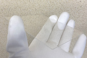
Increase electronic design possibilities with our transparent ceramic PCB solution. 80%-90% transparency and a low thermal resistance. Click to learn more
hushed blade
I'm not sure argon, I'm going off of not much more than some google searches, what I'm finding might not TECHNICALLY be fr4, though it does come up when searching for fr4
distant raven
There is transparent PCB, it’s just really expensive lol
And transparent PCB generally is pretty application specific. It’s not ideal for a lot of projects. Mostly focused on lighting/optics/high heat functions
hushed blade
Yeah, I wouldn't need completely transparent. I want just good enough to see the backlighting and be able to print silkscreen over it because you can get way more detail out of silkscreen vs putting holes in an opaque board
and can have disconnected areas
pale umbra
If your light is strong enough transparent or not doesn't matter 😄
Like my bike light goes throught my hand
knotty tiger
i don't know that you can have an epoxy that's index-matched for transparency and still meet all the other FR-4 specifications. maybe, but if it were possible, i would think that someone would be selling it
void sentinel
Oshpark has a flex option. See what they use for that. It would have cost me 43 to go that route instead of 21.50
So expense seems to be the word
hushed blade
I've seen someone (forget who, sadly) who got every pcb option from jlcpcb and ran a light behind them. Some of them (i remember the red specifically) showed light pretty nicely
you can get decently translucent already, it's just that no manufacturer puts that in writing so it's hard to know without just ordering to see
void sentinel
Of course switching to rush would have doubled it too, so not sure of their system.
Maybe just a brighter light source? Lol
Change of perspective
hushed blade
it's ultimately a problem of scale, probably. they are trying to combine multiple customers orders to fit efficiently on a fixed size plate. the more customers you have a time, the more likely you are to find a perfect fit
and rush means they have to put you on a plate before they can necessarily find that perfect fit, meaning wasted space
void sentinel
They have a tutorial on the motorized slider potentiometers.
Those things are sold out every time I look.
knotty tiger
hushed blade
you can get decently translucent already, it's just that no manufacturer puts th...
i imagine they have no easy way to guarantee a specific transparency, especially because their suppliers might not commit to doing so, either
pale umbra
void sentinel
They have a tutorial on the motorized slider potentiometers.
Those things are so...
what are these for anyway ?
rustic fulcrum
pale umbra
what are these for anyway ?
Making people think your slider controls are haunted
hushed blade
Usually it's so that your electronics can be fairly simple in concept (it's "just" a potentiometer) but you can add fun features like saved settings
pale umbra
Do they connect to standard knobs anyway? Or it's just for the backend inside a panel/enclosure ?
hushed blade
audio mixers use it so save settings and be able to return to them at the press of a button
pale umbra
rustic fulcrum
Making people think your slider controls are haunted
Seems to go well with a magic smoke dispenser 😄
knotty tiger
pale umbra
Seems to go well with a magic smoke dispenser 😄
i think they're also used in lighting boards, so yes, some of them might be connected to smoke dispensers
rustic fulcrum
knotty tiger
i think they're also used in lighting boards, so yes, some of them might be conn...
Ah but that's only the non magic smoke
pale umbra
these are the ones I meant, except mine consume scrap ICs
hushed blade
oooh yeah, lighting control boards I don't have personal experience with, but it makes sense they would have almost identical needs to the audio mixers
pale umbra
like just because the board is dead doesn't mean all the ICs are, some still contain their magic smoke
rustic fulcrum
Just realised that they could also potentially be used to make little indicator displays that only use any power when changing what it's set to
Like very simplistic physical e-ink heh
pale umbra
so you can use a servo to crush them on command and crush them to release the smoke on command 🤣
hushed blade
yeah, linear actuators tend to be pretty expensive and too overdesigned for some uses. I bet there's some subset of uses where those are the most economical solution to just linear motion
pale umbra
if it's motorized enough it's a cheap way to produce linear motions on the attached operator 😄
like if you want to make an electronic that is scared of humans and throw them away when they try to operate it
rustic fulcrum
there really should be a term for when you're about to make an order for parts and are trying to work out if there's another stuff you should get while you're at it
pale umbra
I call it packing my order with deadweight 😄
"Don't kid yourself 5$ oled, you are just there so I don't pay 50$ in shipping"
rustic fulcrum
oh I'm gonna have to pay for shipping regardless, but Pimoroni have a big sale on
hushed blade
adafruit is really good at eliciting that feeling. I have so many uses for rp2040s that I tend to go for that tier, then once I have that much, free shipping is right around the corner...
rustic fulcrum
mumbles something about a 10% off coupon code he knows about for Adafruit
though I guess that'll make it even harder to get free shipping so you'll need to order even more 😉
pale umbra
I'd like motorized switch personally for permanent memory
still need a countermeasure against the user (like shock) if they try to prevent the circuit from physically changing the switch position
void sentinel
Hey everyone. Now that I see my chip is not around and I ordered my boards, what are my next options? It was an ATSAMD21G18...
Do I take the loss and switch my board from the G to the J? ATSAMD21J17D-AU
or can I get them somewhere else? I mean if digikey doesn't have them...
void sentinel
the samd51 and the samd21 are like the same price. lesson 3042 great.
hushed smelt
It happens, sucks bad when it happens but it does happen. Sorry to hear that. 😦 You're going to have to redesign the board anyway most likely so which chip you go with is completely up to you and your design goals.
void sentinel
Maybe I should switch to the rp2040?
You know, for my first smd... Lol
Suggestions? I guess I will get to work on the reflow oven. The good thing is my boards are on a panel with 47 other projects and they should get it back Sept 8.
I am thinking I can get 3 samd21g18 from somewhere maybe 5. I expect to mess up.
Come on, who has a couple?
distant raven
RP2040 might be tricky for your first SMD with its 0.4mm pitch
void sentinel
Ha, tricky and not finishing what I start, are all middle names of mine
I was designing in my brain a circuit board that would solder onto the place where the samd21 should be and break out the needed pins to something else. My qfn breakout board lol
This project was going to start with a mega328 or something but I got a trinket m0 and a feather m0 basic proto and i can only program 1 thing at a time.
I have been bouncing back and forth with c and python
distant raven
You can back order from Digi-Key
void sentinel
I haven't even written any real code. It was slightly modified from the original arduino tutorial
distant raven
Says they have some coming in stock in November
void sentinel
They have like 43,000 on back order
distant raven
Do a back order now and it will ship when they arrive
void sentinel
One of them did lol
distant raven
Back order date given means that subtracting all other back orders, there will be some available on that date
void sentinel
I can't wait that long. A new thing will just happen instead
distant raven
In this case, Digi-Key says Nov 21
How about this stm32 lol https://www.digikey.com/en/products/detail/STM32F215VGT6/2640827
3 in stock and only $18 a piece
Or how about going the ESP32-c3 route and referencing this Adafruit QtPy ESP32-c3?
void sentinel
Those are 18 bucks each. I could just buy something else and reflow the chip off for less
distant raven
They you get RISC-V, WiFi, BLE
void sentinel
Adafriit has 2040 for a buck a piece. I am pretty sure that is my new potential chip
distant raven
0.4mm lead pitch is not very first time friendly.
It’s a great cheap chip, don’t get me wrong. I’ve made tons of rp2040 boards myself
 rain remnant
the ESP32-C3 can be very small
void sentinel
I has esp-cam boards for like 10 each.
I have a rover break out.
That is supposed to be the next gen (wireless)
distant raven
rain remnant
the ESP32-C3 can be very small
0.5mm qfn32 vs 0.4mm QFN56
void sentinel
This is going to be rs485 differential signaling for 200ft distance with potential rf noise
Eh my learning curves are very sharp
distant raven
0.5mm QFN is much easier to solder
distant raven
Sure, that’s fine and all. Are you using an rs485 translator?
void sentinel
I learned eagle and ordered my first board in 2 days
distant raven
Since voltages are well above what most microcontrollers can handle
void sentinel
Max485 chip
Maxim
Ttl to balanced line
It seriously communicates serial with rx tx
It is so basic
The mcp is an i2c
Thermocouple amplifier
All it needs to do is read a temp when called on. Like a good little device that does what it's told and follows directions
distant raven
Gotcha, makes sense
void sentinel

An uno asking these other processors for their data.
ANY processor is overkill.
But it needs one of em
distant raven
Gotcha
void sentinel
This is actually the test unit for the next evolution.
I decided the I want it to be 2.8" or 3.5" instead of the esp32tft

That connects to wifi and sends data to a server of mine. And datalogs locally of course
Then I added a section that uses ajax to grab the latest data and plot it on a web page I made to organise some of the other furnace stuff.

So These things I am actively working on are like entry level dummies. Real simple one task.
Potentially upgradeable
We all know (other than finding chips) the real magic is in the software.
We can buy a webcam for 10 dollars and throw a few hundred lines of code somewhere and that thing can recognize objects and motion, it can tell if you're lying (depends on the code...) Whatever...
tough matrix
void sentinel
Hey everyone. Now that I see my chip is not around and I ordered my boards, what...
was it qfn or qfp?
if qfp, I have some samd21g18 I can resell - for prototyping work
void sentinel
It was qfn lol
tough matrix
:(
void sentinel
I didn't research. It's my bad
I started backwards this whole thing. Failing helps you learn way faster
The fancy nerds just call it iteration
Makes it sound intentional
That's why I like to think I will fail. And I try to figure out how before it happens.
Of course there are always unexpected variables.
Insert an excuse for ignorance. I can't know what I need to know until I need to know it.
At that point I either know it or...
tough matrix
or you can order one last chip from lcsc for whopping $15 + shipping
ATSAMD21G18A-MU Microchip Tech US$14.053 - 32KB 256K@x8bit -40℃~+85℃ 1.62V~3.6V ARM Cortex-M0 1@x1ch/10bit 1@x14ch/12bit Internal oscillator included 48MHz 38 QFN-48 Microcontroller Units (MCUs/MPUs/SOCs) ROHS datasheet, price, inventory C966903
void sentinel
This one is $12...
https://www.adafruit.com/product/3727
What's smaller than a Feather but larger than a Trinket? It's an Adafruit ItsyBitsy M0 Express! Small, powerful, with a rockin' ATSAMD21 Cortex M0 processor running at 48 MHz - ...
It comes with extra parts...
Oh they only had 1 in stock anyway lol I need 3 or 4 at least. I am picturing 5 for somewhere between 25 and 50
They don't even have 32u4 in stock. See it's like the world is forced to evolve.
void sentinel
I never got into the attiny or pics or that propeller chip. That was the generation before Arduino basically. Like 20 years ago it seems.
woven bluff
I don't even consider QFN for hand solder... you can not even stick a probe on it if something goes wrong.
distant raven
Sure you can, you just need needle probes
Get yourself a kit like this Bionso 25-Piece Multimeter Leads Kit, Professional and Upgraded Test Leads Set with Replaceable Gold-Plated Multimeter Probes, Alligator Clips, Test Hooks and Back Probe Pins. https://a.co/d/4qAshGL
woven bluff
I have this design I wanted to send to fab half a year ago, but every time I open it I can find something to improve...
 light prism
I need a quick and dirty way to power a project from usb-c. 5V ~50mA is all i need, but I need some kind of short-circuit protection. (power is being supplied to pogo-pins that can easily be shorted). any thoughts?
light prism
maybe I'm over thinking this and should just put a small resistor inline to limit the current to like 200ma?
woven bluff
depends how much voltage drop you can tolerate
light prism
fair - this is feeding a bq25100 battery charger ic, which has a min input voltage of 4.45
time for some maths
i guess it works out then that a ~10ohm resistor would give me 500ma in a short situation, and about a .5v drop at 50mA charging.
seems borderline though
woven bluff
be aware there's already a short-circuit protection in usb host controller, it may trip at 500mA.
rustic fulcrum
light prism
I need a quick and dirty way to power a project from usb-c. 5V ~50mA is all i ne...
An eFuse?
light prism
it does seem like that is what i want - but is there a way to implement that quickly? i don't have time to get a board made
looking for an inline option or something with a breakout board that already exists
looks like TI may have some evaluation boards that could work
rustic fulcrum
Looks like there's some through-hole ones too
Plus might be able to just make a circuit yourself https://maker.pro/tinycircuits/projects/introduction-of-protection-circuit-for-short-circuit
light prism
i'm a mechanical engineer wearing an EE hat. That looks scary to me
this should save my bacon: https://www.digikey.com/en/products/detail/texas-instruments/TPS2596EVM/10445317
light prism
i have budget and space. I wouldn't mind saving some money, but time is probably the most important thing here
rustic fulcrum
Assuming that all the extra things it can do don't get in the way, these are available as through hole
oh the link blocking bot is not my favourite thing
This is probably overkill and there's likely a much better way of doing it that someone else might be able to point out, but a few of these seem to have short circuit protection that could maybe work?
light prism
i gotta run for now but will give that a look through in the morning. thanks for the help
rustic fulcrum
light prism
i gotta run for now but will give that a look through in the morning. thanks for...
Np, though I just noticed the supply current and ohh that's one is a bad plan considering how much supply current it uses (it'll eat your battery). Are you aware of the little SMT breakouts Adafruit sell?
rustic fulcrum
light prism
i gotta run for now but will give that a look through in the morning. thanks for...
Yeah, I think that's a better plan. Combine a SMT breakout https://www.adafruit.com/category/475 with an actual eFuse chip that's designed for this. You could also possibly use the magnetic connectors instead of your pogo pins, which are magnetically polarised so you have to somewhat fight to get them the wrong way around, or possibly change the design to make it harder to physically do it otherwise? I also just discovered that RS Components will actually ship to the US, albeit with pricier shipping and import tax. If you've not come across it, Octopart is quite handy to to search for stuff across retailers: https://octopart.com
woven bluff
I'd opt for power switch IC, they are cheap and come with all sorts of protections
e.g. TPS2049DR
rustic fulcrum
woven bluff
e.g. TPS2049DR
Think these would work? I'm getting confused by the different SMT package names versus the breakout Adafruit sells, not sure which if any would be compatible: https://www.digikey.co.uk/en/products/filter/power-management-pmic/power-distribution-switches-load-drivers/726?s=N4IgjCBcpgbFoDGUBmBDANgZwKYBoQB7KAbRABYAGAVnICZyQCraBmapim8qkAXQIAHAC5QQAZWEAnAJYA7AOYgAvgTDq6CEMkjps%2BIqRCxKPCATqU6ADgDsrTmFvUw5CAJAixk2YpVrrMGstHT1cAmJIMlZ2AE5qYIIY6liTTlhrOhdzEGTUxiS423hClNtbTjzrSk5ye1pEkGpnSnZa6tjXSszMgtyeuu6bWA4kzNjTIYnR-rpYuhyqBcmPL0gJaXklVRAAWk1obShpAFcDSLIZ2P5lW6A
distant raven
Personally, I like this load switch. https://www.digikey.com/en/products/detail/TPS22917LDBVR/15904219
12.5W max rating is pretty stout for $0.65
rustic fulcrum
distant raven
Personally, I like this load switch. https://www.digikey.com/en/products/detail/...
Sure it has short circuit protection? https://www.ti.com/lit/ds/symlink/tps22917.pdf?ts=1661965499359
distant raven
I didn't claim it did, I was just chiming in with a load switch i've used and like
rustic fulcrum
distant raven
I didn't claim it did, I was just chiming in with a load switch i've used and li...
Ah sure, it's just that's the thing they want protection against
distant raven
you could get short circuit protection with a PTC
depending on your needs and anticipated power source, you can choke it at 500mA, 1A, up to like 280A lol
something like this would work in most case https://www.digikey.com/en/products/detail/bel-fuse-inc/0ZCH0110AF2E/12342860
pale umbra
"allowing just enough residual current flow to maintain the block’s internal temperature at 125C" cool it can boil water for my coffee!
distant raven
🙂
void sentinel
My new 2040 collection
 void sentinel
They are tiny... that is a needle tool I have and my smallest iron tip. but according to legend, I would want to reflow this in an oven or maybe on a plate and or with a hot air gun. Not with an iron. If that is what was meant by hand solder?
Not saying I can do it. I am just mentioning that I might also have a microscope. So at least I can see all the shorts...
and who knows, ok you know who you are, maybe I can solder wick it off lol
 hushed smelt
oh i'm using that pic for my github
it's actually kinda hard to find a picture of a bunch of same type of boards. https://github.com/DJDevon3/My_Circuit_Python_Projects/tree/main/Boards/raspberrypi
i have a hw design problem maybe someone can help with. i'm using an RP Pico with MCP23017 gpio expanders. Unsure what to do with the interrupt pins.
I've seen some diagrams online that chains each expander to each other and 3v3 with a pull down resistor. That just seems odd to me.

interrupts are on U5 and U6 inta A & B each.
breaking them out to pads right now just in case because i'm not sure if they're required or if they are how to wire them up in this scenario.
wouldn't it be better to run the interrupt lines straight to the Pico and let the Pico's GPIO handle the interrupt to both of them individually instead of daisy chaining them?
void sentinel
that is a neat chip. i thought the interupts were input. they are configurable to potentially be triggered on change of the GP inputs so I guess each chip could be 2 different 8 bit inputs. But what do you WANT to do with them? I am guessing you were just using u5 and u6 as pass through expanders? so you have bonus hardware to write code for? or to not... lol
analog bits too
not sure how they get used when you have in and out on the same channel
nevermind the analog bits are the address
I cleaned my tip...
 hushed smelt
think i figured out the interrupts yeah. as far as i can tell they're unnecessary if i have enough i2c busses for each. the pico has 2 and i'm only using 2 expanders. i think interrupts would be more handy if i was doing something Liz Clark's xylophone and had like 8 with some needing to be daisy chained.
moved some of the SPI pins and other stuff. think it's just about cleaned up now.

added a reset button too because it's a pico.
i might add jump pads for the expander reset too just to be safe in case it might need a resistor
expanders are just a way to add 16 step switches. pico alone doesn't have enough gpio.
interrupts being inputs makes a lot more sense. if i run them to pico gpio then i can control interrupts from software, hopefully that'll work.
i don't know if they're necessary in my design, yeah it'll be an additional feature hopefully unneeded. i'd rather not have to deal with interrupts in the design if possible, interrupts i feel like would just slow it down.
basically @drowsy drift 's picostepseq except with 16 step switches https://github.com/todbot/picostepseq
 dry jetty
Not sure this is a HW question: I did a design blunder - and now I have to find a way to use a digital pin for measuring analog. From my days with Parallax/Propeller I remember a way where the analog in charges a small capacitor, the digital pin is set as output with a 'zero', quickly disharges the capacitor, then it is set as input and measures the time it takes to recharge the capacitor (dependant on analog in signal level) to the level when a 'one' is detected. This enables a (crude) calculation of the AI level. Is this feasible/done on a Feather M4? It's only for an LDR, so accuracy is not imporant.
knotty tiger
dry jetty
Not sure this is a HW question: I did a design blunder - and now I have to find ...
this is roughly how the Apple II reads the joystick inputs, from what i recall, but it relies on your analog voltage source having a known impedance (otherwise the capacitor charging rate is unpredictable)
knotty tiger
dry jetty
Not sure this is a HW question: I did a design blunder - and now I have to find ...
if you have the actual analog pin available and simply not connected, it might be easier to wire-patch the boards to reroute the signal
 outer adder
Hello,do anybody have any idea how cound I implement hot-plug in MCP9808 sensor in SW and HW.Thanks in advance
light prism
@woven bluff thanks, TPS2049 is exactly what I was looking for!
void sentinel
outer adder
Hello,do anybody have any idea how cound I implement hot-plug in MCP9808 sensor ...
It probably throws an error and shuts down. If python use try/except and ignore the error.
Do you have a breakout board? I2c? How are you using it?
I mean I know it is i2c I am just like wondering why it is unplugging and all
dry jetty
knotty tiger
if you have the actual analog pin available and simply not connected, it might b...
No such luck 😭
outer adder
void sentinel
Do you have a breakout board? I2c? How are you using it?
Yes,I have a breakout board from Adafruit and the bus is i2c.
void sentinel
Why is it unplugging?
outer adder
its is not unplugging,but how can it be implemented in hardware hotplugging.What changes should a do,in HW part firstly in difference to a normal connection.MPU is a RPi.I a beginner maybe Im saying smth wrong
void sentinel
It sounds like you want to write code for something that you aren't doing?
What language are you coding in?
Hot plugging is when you plug or unplug when the connection has power
You said you are not unplugging. Which is it?
outer adder
void sentinel
You said you are not unplugging. Which is it?
I have started to do it,but I am not at this point.So I thought to ask before,and not after I get to that point.Language is Python.Yeah I want to hotplug the sensor,maybe i understood it wrong what you wrote
distant raven
outer adder
its is not unplugging,but how can it be implemented in hardware hotplugging.What...
For i2c you would use an i2c terminator
Basically pulls the lines up before connecting them. Used for hot swapping

I2C stands for Inter-Integrated-Circuit communications, it's meant for short distances on a PCB or subassembly. But, hey, we're engineers, and we like to push the limits of ...
outer adder
its not possible without a terminator?
distant raven
You run the risk of a fault of the buses are connected at a bad clock interval causing you to have to reset the board
outer adder
understand,thanks for the advice
rustic fulcrum
outer adder
its is not unplugging,but how can it be implemented in hardware hotplugging.What...
I think this is probably the board you want, the one @distant raven suggested is great if you want to make them work on super long cables, but this is explicitly to enable hot swapping: https://www.adafruit.com/product/5159

As we've been adding STEMMA QT connectors to our breakouts and dev boards, folks have been really enjoying the simplicity and speed of plugging in I2C sensors and devices for quick ...
distant raven
rustic fulcrum
I think this is probably the board you want, the one <@728676724522352733> sugge...
Ah you’re right. Should have just searched hot swap lol
rustic fulcrum
I do keep being tempted by the LTC4311 tbh, one of the projects I want to do is an outdoor temp/humidity sensor, and all of the power issues, and to some extent, some of the waterproofing ones, go away if I can just get a cable outside which attaches directly to the sensor board.
rustic fulcrum
rustic fulcrum
I think this is probably the board you want, the one <@728676724522352733> sugge...
That said, I'd expect you'd probably need to be sure to make your code a bit tolerant of the possibility of a I2C device it expected to be there, suddenly not being there, maybe in part via wiring to the ready pin on the breakout.
Can I ask what your project is that it needs to handle the sensor being disconnected without being reset @outer adder ?
rustic fulcrum
Does anyone know of a service that'll make a super basic breakout board for a SMT chip you send them? Adafruit make SMT adapters for a few chips but only really the larger ones and even their pins are teeny though that I'm not sure how likely it is that I'll be able to successfully solder them. Keep thinking it'd be an awesome service for someone like Digikey to partner with someone to offer.
distant raven
rustic fulcrum
Does anyone know of a service that'll make a super basic breakout board for a SM...
Would be as simple as getting the part into eagle or KiCAD, breaking out to headers and sending off to OshPark, Digi-Key’s PCB service, JLCPCB, etc..
rustic fulcrum
distant raven
Would be as simple as getting the part into eagle or KiCAD, breaking out to head...
Ah, I assumed that those companies didn't do the pick & place + soldering side of things for you
rustic fulcrum
distant raven
And PCBWay
has a monotone YouTube ad flashback
distant raven
Lol
rustic fulcrum
I still can't quite figure out if that voiceover is a real person or text-to-speech
rustic fulcrum
distant raven
Would be as simple as getting the part into eagle or KiCAD, breaking out to head...
Also I think you're overestimating my grasp of "simple" in terms of having to actually design a board first 😉
It also took me way too long to realise that PCBWay's quote was telling me that it was the same price to get 50 of them as ordering a single board.
knotty tiger
i wonder if there are any standard EDA parts libraries that have SMT-to-DIP breakouts
rustic fulcrum
Hmm, how feasible might it be for a noob to get the super mini hotplate and just order teeny PCBs and then actually put parts on there myself with paste (?)? I have no idea how any of this works
Or would I need a custom stencil for the paste?
knotty tiger
i thought i've seen retail solder stencils for common SMD footprints
distant raven
knotty tiger
i thought i've seen retail solder stencils for common SMD footprints
Long link but that’s a common part stencil
It’s for a kit but you could totally use it for other things
rustic fulcrum
hmmmmmmm
rustic fulcrum
so I'd design a breakout board for the part/see if I can find a premade one, order it from someone, then get the stencil, place it over it, brush (?) solder paste over it, carefully place the chip on it, pop it on the teeny hotplate, heat it up, then cool it down, and then that's that?
distant raven
Yup
The stencil part takes a little practice but definitely fairly easy to get the hang of
rustic fulcrum
though I guess admittedly the chip I wanted isn't actually in stock anywhere. Is there a chip shortage? 😉
distant raven
Chip shortage? Never heard of it
pale umbra
nah the slves were full last I looked especially plain and bbq
void sentinel
outer adder
understand,thanks for the advice
also if you are trying to talk to (read write etc) a device that is not there, you will get a connection error. this type of thing will need to be implemented:
except ConnectionError: or the system will halt
void sentinel
rustic fulcrum
though I guess admittedly the chip I wanted isn't actually in stock anywhere. Is...
that sounds horrible how can that sort of thing happen to good people?
it seems like we are heading down a similar path
rustic fulcrum
void sentinel
that sounds horrible how can that sort of thing happen to good people?
Wait, could this have something to do with how UPS messed up delivering my Pimoroni order today? Did the chips just not exist and the order was an elaborate ruse?
void sentinel
I have a device I started as a nest thermostat alt. It was really to replace an existing thermostat that had a broken wire to the up button on the plastic ribbon cable...
As it started to evolve, I got the esp32-s2 and started working on a different datalogger/ display/ almost controller...
I stopped working on the basic unit and realized what would be cool if I had the MCP9808 and the MCP9600 even thought the hot junction on the MCP9600 is similar to what I would get from the 9808, I wanted dedicated chips. And I wanted it to switch through software not hardware... I had thought of hotplugging, but that isn't needed really.

right when I was like, "ok this works. lets print an enclosure" iterating happened. It never stops. I have change issues...
rustic fulcrum
void sentinel
right when I was like, "ok this works. lets print an enclosure" iterating happen...
 void sentinel
anyone familiar with 4-20mA control loops? circuitry? These are usually 24vdc. not necesarily, but in my case that will be the design. basically a 5k pot in series with 1k ohms could do the job. But I want software control not a pot...
It's the output my controller needs to um control things.
knotty tiger
you want to somehow output a 4-20mA current loop signal from a microcontroller?
knotty tiger
void sentinel
anyone familiar with 4-20mA control loops? circuitry? These are usually 24vdc. n...
i found these with a quick search; haven't investigated thoroughly https://www.maximintegrated.com/en/design/technical-documents/app-notes/6/6508.html
https://www.ti.com/lit/ds/symlink/dac161s997.pdf
is your board being loop-powered? or is it providing loop power?
How to use a highly configurable analog front-end for 4-20mA sensor transmitter.
void sentinel
dang that is a 32 pin qfn or whatever
it is integrated. but dang. I have been researching the op amp circuitry involved in the measuricating
Yup there is the magic:
 knotty tiger
yeah, a current-sensing op amp with a hybrid analog/digital feedback loop wrapped around it might be a way to homebrew one
void sentinel
I actually bought one of these: https://www.amazon.com/gp/product/B07BDJJNK3
a while ago and it is very simple. I just wasn't sure if anyone here was into that sort of thing and would have refined something.
I mean besides maxim and microchip lol

Features: Using single-chip embedded technology. Implement the industry standard voltage (0-24V) into an industry standard current (0-20mA, 4-20mA). Linear output, output signal can be directly connected to the AD converter. Can be connected with a microcontroller with AD function. Easy to operat...
Uses an LM224 from ti
and a npn transistor for the power like that q1 up there
BCP56
it's fun to brainstorm here
I can't wait to put a drop of nail polish on a pot. I'm usually breaking them off...
I wanna be like open source Honeywell/Yokogawa (I don't)
That is funny because in the 90s I did audio video security for auto and commercial/residential. Before I got into ADT type of security stuffs the car audio was my thing. I was the one that made the cars go boom... That was also around when I was schooling so I really did want to be like Alpine and Bose. crazy magic sound waveforms and to imagine installing a system in a car where the head unit says your name and the amps have your symbols on them? That is what I wanted.

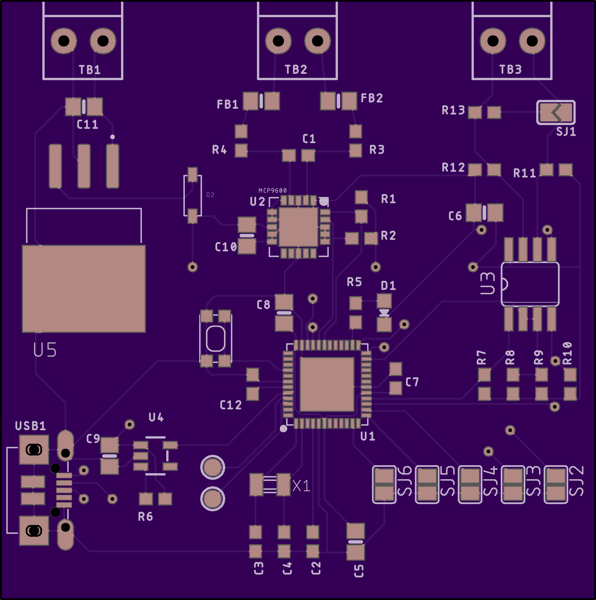
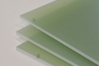
It is quiet here at night 😉
supple pollen
Heh, I was in the Kenwood/Pioneer/Sony camp.
Having become disenchanted with Blaupunkt after they seemed to lose their way.
void sentinel
that was entry level. like the jensen 200w everyone had one of them with some 6x9s
because who cares about physics and soft cones
I still have a pair of 10 solobarics in my basement
talk about physics ha
Orion was one of the best speakers I hooked up one 18" in a honda civic.
spl was way way up there


I could just throw that in a pile and have noise. I mean sound.
Alpine had those units with the 6 green buttons. Those were the very best for years. Pretty much until navigation came out.
There were some rare ones that no one could afford like Harmon Kardon. Those weren't around much though.
Around then is also when auto manufacturers started partnering with audio manufacturers.
rustic fulcrum
void sentinel
dang that is a 32 pin qfn or whatever

Beguiled by a fancy new chip that is only available in a QFP or QFN pinout? This breakout PCB set will make your life much much easier and get you prototyping faster than ever. One side has ...
Huh, I just had a terrible idea. I wonder if it might be possible to buy an Adafruit breakout board with a chip on it that's the same package as you want, pop it on a teeny hotplate, pop the existing chip off, and then replace it with one you want a breakout for
void sentinel
it is. and if adafruit doesn't make it, sparky fun time probably did.
void sentinel
Look at this mess...
 woven bluff
that's what happens when you add stuff to the schematic. I don't think any EDA software has automatic placement
void sentinel
It looks the same lol. red lines green lines black text
 void sentinel
woven bluff
that's what happens when you add stuff to the schematic. I don't think any EDA s...
void sentinel
woven bluff
that's what happens when you add stuff to the schematic. I don't think any EDA s...
I know I was just enjoying doing this again
woven bluff
any idea on human presence detector?
I tried PIR, but it won't work if I remain still.
and amg8833 breakout board is too big to fit in my project
 supple pollen
Clever use of the double decimals as colons
outer adder
void sentinel
also if you are trying to talk to (read write etc) a device that is not there, y...
Yes,good idea.For the API,you use that one from Adafruit in Github(Python version ofc)?
outer adder
rustic fulcrum
Can I ask what your project is that it needs to handle the sensor being disconne...
So is the requirement.The idea is to have 8 sensors in a chain and this needs to be hotpluggable.I dont think it will be used as hotpluggable device but so is the requirement
void sentinel
Other than scanning temp sensors pir is funny. i used rf blankets to detect motion. The thing is, presence and motion are different. do you have entrances or exits that have to be passed? beam break, door sensor, pir on two sides of an entrance. pir just isnt good for anything but certain motion. Image object detection is making that obsolete I feel. Nothing like a good old yawcam or whatever. Even espcam stuff has object detection codes laying around.
a lidar could paint a map then scan for new objects. expensive though
i vote with timer after pir detects. just like motion sensing lights work...
what is it for? lol
 cunning hull
by any chance there is a guide in how to build something like this: https://www.adafruit.com/product/5001

This funky user interface element is reminiscent of the original clicking scroll wheel interface on the first iPods. It's a fancy mechanical kit but has an intuitiveness that is hard to ...
specially interested in how slim it is an the rotay enc with a button in the middle
void sentinel
I saw that and I forgot to buy it. grrr. thanks though I can add it to my cart
cunning hull
out of stock 😅
thats why i want to build it, to hve some thing like it and learn to build a piece of hardware
void sentinel
at the bottom of almost every product is a link to the learn site

Adafruit Learning System
A nifty, little directional rotary encoder kit!
and they recommend you buy the break out. It looks pretty simple. But fancy
and with that neopixel ring, perfect
cunning hull
yeah how to use it but not how to build it, i spcially want the really slim rotary encoder it uses, cant find a similar piece online
void sentinel
what do you mean how to "build it"
the actual encoder?
and the buttons
in a plastic housing? all that?
look up how encoders work. there are a few kinds the ones I just bought are quadrature style. they have 2 switches whos oututput is a square wave 90 degrees out of sync
cunning hull
yeah, at lest get that nice slim wheel encoder it uses and i can build the rest around it
void sentinel
this style might be hid with a slim knob like that
https://www.amazon.com/uxcell-Encoder-Switch-Scroll-Repair/dp/B07T3WTPSR

uxcell 25 Pcs Encoder Switch Mouse Encoder Scroll Wheel Repair Part Switch 5mm 7mm 9mm 11mm 13mm
cunning hull
thats missing the hollow are in the center to place a button, the closest i found so far is this but is big and bulky https://www.mouser.com/ProductDetail/Bourns/PER561-P115-N0015?qs=IS%252B4QmGtzzrAUR9c1BGEfg%3D%3D
that piece but slim would be perfect
void sentinel
actually the best would probably be the thumbwheel to have slits in it and have photo electric sensors (2 of course) detecting the slits. that could be pretty compact
you could even have the pattern on the underside with the sensors reflecting off the pattern instead of the beam break way
I mean if you are going to "build it" yourself...
cunning hull
hey thats not a bad idea, i havent thought about approaching it that way
void sentinel
are you familiar with the balls in old mice or trackballs the way they work? or capacitive touch screen they have round ones. people make watches and all kinds of things with them
a pseudo rotary encoder
imagine walking up to the super secret spy gate and there is a coin slot, but the coin only goes in half way and it rotates something and there may be holes or special reflective surfaces or embedded chips like rfid
oh oh
hall effect sensors
cunning hull
so much to play around with, so little time
void sentinel
rotary encoder with hall effect sensors. that might be really easy
I love choices. I spend all my time choosing and not doing
cunning hull
i feel you
vast flume
Have any of you used Flux.ai for pcb design?
I just got into the beta for it
Curious about everyone's thoughts on its current state
 pure gorge
Just making sure, is this a good PCM1860 circuit? Anything I should change? It's just meant to convert analog audio to I2S for my raspberry pi https://media.discordapp.net/attachments/742686081824194616/1015308199177498624/board.png https://media.discordapp.net/attachments/742686081824194616/1015308199596924988/pcb.png


 distant raven
vast flume
Have any of you used Flux.ai for pcb design?
distant raven
vast flume
Have any of you used Flux.ai for pcb design?
I’ve had an account for… almost a year? 8 months? It’s okay, it hasn’t worked very well for me though there are people it is a great tool for.
vast flume
So I finally got around to testing my hotplate...
It doesn't work
The pcb hasn't arrived yet, so I just thermal glued the heating element to the aluminum sheet, but it seems that too much heat is being transferred from the sheet to the air for the aluminum sheet to heat up hot enough
pale umbra
the sides of it going to be 3d printed plastic ?
vast flume
Yeah but the sheet mounts to the base through 3" metal standoffs
So theres an air gap between it and the petg
vast flume
I'm going to try running 2 50w heating elements instead of 1
woven bluff
I'm trying to make a plasma arc lighter with fly-back convertor, but I couldn't find compact HV transformer for sell.
is it possible to make a transformer-less design?
boost convertor can go 1KV with SiC FET. maybe 10 stages of voltage multiplier after that?
supple pollen
woven bluff
I'm trying to make a plasma arc lighter with fly-back convertor, but I couldn't ...
There are a few approaches. One is to use a small inductor and wind a few turns of wire over it to serve as the primary. I've also seen people try to use strobe trigger transformers or capacitor charging transformers. However, the characteristics for an arc lighter are somewhat demanding so it's normally a custom unit.
knotty tiger
large voltage ratios are more efficient to achieve using inductors or transformers; i think capacitor-based solutions end up being too lossy for any substantial current, though i forget the exact reasons
supple pollen
I think that's why they're proposing a boost converter followed by a multiplier
knotty tiger
oh ok, maybe i misread somewhere that they were asking about a switched-capacitor converter somehow
supple pollen
That may have been the other thread about LCD contrast, I dunno
Amusingly, I'm looking at a switched capacitor converter to boost 9V to 25V for another project.
pale umbra
Saw a 1200W (25V to 240V) power supply yesterday for different uses (computer, lab, etc) I bet it would light my LCD up really well in every meanings of the word 😄