#help-with-linux-sbcs
1 messages · Page 14 of 1
 uncut lagoon
 raw solar
I didn't notice when I ordered, lol
uncut lagoon
you can handle them really easily in python too
raw solar
noice
uncut lagoon
i made a script (which is always running in the background) that maps the buttons to up and down, long-press on the top to enter and the bottom one to turn off the backlight
raw solar
Hmm... I could probably do multiple choice and have 1 button do toggle choice and the other select, if I wanted to be minimalist...
raw solar
I mean, that would only take 2 lines to explain XD
uncut lagoon
but someone that uses it, will think that bottom moves it to the bottom
brains are dumb
which is why i did this way
besides, the worst that will happen is that they will have to learn to long-press
and i use 1 line to explain it all
raw solar
long-presses aren't intuitive either, it's only intuitive if you have a standardized layout with lots of buttons
either way it takes a line to explain, lol
I'll probably have more buttons
uncut lagoon
yes, more buttons is a good idea
and i know that long-press isn't intuitive
but it's better than leading to mistakes
raw solar
I mean, hopefully it'll take more than one choice to ruin the game XD but I can make a tutorial so you can't get to the game without figuring out and acknowledging the controls
uncut lagoon
that's actually a very good idea
 restive jungle
Hey I’m assuming this is a good place to post this but can I screen share the screen of a raspberry pi to a android tablet with a cosmos app
Custom
 paper compass
restive jungle
Hey I’m assuming this is a good place to post this but can I screen share the sc...
paper compass
restive jungle
Hey I’m assuming this is a good place to post this but can I screen share the sc...
You can start a VNC server with view only mode, and I'm sure there are libraries out there for embedding a VNC client into an Android app.
 pale moat
hi
i try to install nextcloud on my pi but when i open the page it shows this?
anybody know whats wrong?
 paper compass
pale moat
hi
i try to install nextcloud on my pi but when i open the page it shows this?
a...
paper compass
pale moat
hi
i try to install nextcloud on my pi but when i open the page it shows this?
a...
that's hard to read for me, mind pasting in the text instead of an image?
restive jungle
paper compass
You can start a VNC server with view only mode, and I'm sure there are libraries...
Is thare a way I can do it like a wireless hdmi transmitter
pale moat
could someone pls help me
paper compass
pale moat
could someone pls help me
I was reading the error message. That's not much to go on, if you'd like more help you could list off all the information you know about your situation, what version pi? how did you install nextcloud? Was this a clean raspberry pi install? what OS?
pale moat
i installed it on a raspberry pi 4 on raspberry pi os lite i installed it by watching a german youtuber and followed his step
i think it has something to do with php
as i installed php7.2.x it said required 7.3 but now i got that installed and it doesnt work
restive jungle
paper compass
You can start a VNC server with view only mode, and I'm sure there are libraries...
Not though a VM I want to take the picture from a camera on my robot and send the feed back to the app but have it go through a jetson nano for obstacle avoidance
paper compass
restive jungle
Not though a VM I want to take the picture from a camera on my robot and send t...
I'm not sure I understand, you want to take the HDMI output from your pi, that has a camera image on it, and open that in your android app? Are you looking for a hardware solution? There are devices that take HDMI input and create an IP server, but they're not cheap and are rarely worth it IMO.
https://www.amazon.com/StarTech-com-Gigabit-Ethernet-Receiver-ST12MHDLAN/dp/B00CLMN8HW
Amazon.com: StarTech.com HDMI Video Over IP Gigabit LAN Ethernet Receiver for ST12MHDLAN - 1080p - HDMI Extender Over Cat6 Extender Kit (ST12MHDLANRX), Black: Home Audio & Theater
paper compass
restive jungle
Not though a VM I want to take the picture from a camera on my robot and send t...
Or is it
camera -> robot (pi) -> jetson nano -> android app?
restive jungle
Camera -> jetson nano ->android app
paper compass
restive jungle
Camera -> jetson nano ->android app
Oh. Heh, I thought there was a raspberry pi involved.
For that, you might need to add a wifi card and then you can use ffmpeg and other tools to serve the camera over the network, the jetson being a hotspot if no wifi is available or impractical. There's probably even an out-of-the-box python library if you search for one. What's the jetson running? is it a main distro or something NVIDIA cooked up? For all that trouble I'd probably just make a web app instead of an android one, but that's dealer's choice.
paper compass
restive jungle
Camera -> jetson nano ->android app
Does the Jetson Nano have WiFi or Bluetooth built in? IIRC I don't think it does. If you add bluetooth, you could set it up as a Bluetooth Object Push Profile (OPP) Server, and send images to android that way ... though that's sending files, not a stream.
There is that ethernet jack, you could get a little device that runs DD-WRT (chances are you might have one you can repurpose) and bridge the ethernet to wifi.
Something like this maybe https://www.amazon.com/dp/B073TSK26W
Amazon.com: GL.iNET GL-MT300N-V2 Wireless Mini Portable Travel Router, Mobile Hotspot in Pocket, WiFi Repeater Bridge, Range Extender, OpenVPN Client, 300Mbps High Performance, 128MB RAM: Electronics
 still notch
i am building a birdcam w/ rasp pi zero w + rasp pi camera. i am streaming to YouTube Live. I barely know what i am doing... the command i use to stream raspivid -o - -t 0 -vf -hf -fps 10 -b 400000 | ffmpeg -thread_queue_size 10240 -r -re -ar 44100 -ac 2 -acodec pcm_s16le -f s16le -ac 2 -i /dev/zero -f h264 -i - -vcodec copy -acodec aac -ab 128k -g 20 -strict experimental -f flv rtmp://a.rtmp.youtube.com/live2/STREAM-KEY causes an error on the YouTube Live side: ouTube is not receiving enough video to maintain smooth streaming. As such, viewers will experience buffering. on the Rasp Pi, i get the errors: [h264 @ 0x310a220] Thread message queue blocking; consider raising the thread_queue_size option (current value: 8) [flv @ 0x31e4c40] Timestamps are unset in a packet for stream 0. This is deprecated and will stop working in the future. Fix your code to set the timestamps properly I've gone through the options to ffmpeg and raspivid and thought I had then set ok. But apparently i don't. i am hoping someone might be able to nudge me into the right direction to get a better live stream. perhaps i shouldn't be using YouTube live....however, i wanted to be able to watch the birds from a Smart Tv... advice greatly appreciated.
paper compass
still notch
i am building a birdcam w/ rasp pi zero w + rasp pi camera. i am streaming to Y...
I've been thinking about doing the same, but never thought about using YouTube Live, that's clever. I might try out this docker image https://blog.alexellis.io/live-stream-with-docker/
Alex Ellis' Blog
With this guide you'll be live-streaming in minutes instead of hours with a tried and tested Docker image and your Raspberry Pi. What will you stream?
paper compass
still notch
i am building a birdcam w/ rasp pi zero w + rasp pi camera. i am streaming to Y...
If you dig through the repo for that docker image, his command is pretty close to yours https://github.com/alexellis/raspberrypi-youtube-streaming/blob/master/streaming/entry.sh
raspivid -o - -t 0 -w 1920 -h 1080 -fps 40 -b 8000000 -g 40 | ffmpeg -re -ar 44100 -ac 2 -acodec pcm_s16le -f s16le -ac 2 -i /dev/zero -f h264 -i pipe:0 -c:v copy -c:a aac -ab 128k -g 40 -strict experimental -f flv -r 30 rtmp://a.rtmp.youtube.com/live2/$1

GitHub
Stream straight to YouTube from your Raspberry Pi with Docker. - alexellis/raspberrypi-youtube-streaming
 ionic stag
Anyone know if Raspbian Lite Buster comes pre-enabled with the Serial Login shell?
raw solar
I believe that that, along with SSH and all, are disabled by default on all Raspbian flavors
raw solar
That's a good question
Here's a wiki about it https://elinux.org/RPi_Serial_Connection
 hardy plaza
Isn't that simply configured via raspi-config?
raw solar
Actually yeah I think it is
But this line would apply if you, say, are trying to set up but don't have a display or network: NOTE FOR RASPBERRY PI 3: The Raspberry pi 3 has changed things a bit and you might need to add the option enable_uart=1 at the end of /boot/config.txt
ionic stag
Can I power my pi zero from my 3b+ by hooking the 5v pins together or do I need to grab another micro-usb cable for power for the zero?
hardy plaza
ionic stag
Can I power my pi zero from my 3b+ by hooking the 5v pins together or do I need ...
You're probably asking too much of your power supply if you're not careful. Add up the power requirements of both and make sure that the cumulative amps is still less than your power supply. If your power supply can handle it there's no issue in running them from the same one. Make sure they share a common ground (V-, the minus/black wire from your supply).
A Pi 3 B+ takes I think about 2.5 amps so that's often at the limit of what a USB power supply can do.
ionic stag
Unfortunate, more cable time!
hardy plaza
I think a lot of Pi problems are power supply problems.
ionic stag
By the way, is there any way to determine which serial is the pi zero from a pi 3b+? Or do I just try them all?
(I dug out my Pi 3B+ and am trying to serial into it to see what's going on)
hardy plaza
I don't know but you might check Rx and Tx, or the UART pins
ionic stag
They're 8 & 10 right?
hardy plaza
I don't have a pinout handy, but a Google Image search for Raspberry Pi GPIO will tell you.
ionic stag
I seem to have it right. Rx - Tx and Tx - Rx is the right way, right? Not Tx -Tx and Rx - Rx?
ionic stag
ONE AND A HALF WEEKS LATER
I HAVE A SHELL
WHOOOOOOOOOOOOOOOOOOOOOOOOOOOOOOOOOOOOOOOOOOOOOOOOOOOOOOOOOOOOOOOOOOOOOOOOOOOOOOOOO
I don't think that should be doing that
pi@raspberrypi:~$ sudo iwlist wlan0 scan
wlan0     Scan completed :
          Cell 01 - Address: XX:XX:XX:XX:XX:XX
                    Channel:11
                    Frequency:2.462 GHz (Channel 11)
                    Quality=12/70  Signal level=-98 dBm
                    Encryption key:on
                    ESSID:""
                    Bit Rates:1 Mb/s; 2 Mb/s; 5.5 Mb/s; 11 Mb/s; 6 Mb/s
                              9 Mb/s; 12 Mb/s; 18 Mb/s
                    Bit Rates:24 Mb/s; 36 Mb/s; 48 Mb/s; 54 Mb/s
                    Mode:Master
                    Extra:tsf=0000000000000000
                    Extra: Last beacon: 80ms ago
                    IE: Unknown: 0000
                    IE: Unknown: 010882848B960C121824
                    IE: Unknown: 03010B
                    IE: Unknown: 050401020000
                    IE: Unknown: 2A0104
                    IE: Unknown: 32043048606C
                    IE: IEEE 802.11i/WPA2 Version 1
                        Group Cipher : CCMP
                        Pairwise Ciphers (1) : CCMP
                        Authentication Suites (1) : PSK
                    IE: Unknown: 3B025100
                    IE: Unknown: 2D1A0C001DFFFF000000000000000090000100000000000                        000000000
                    IE: Unknown: 3D160B00000000000000000000000000000000000000000                        0
                    IE: Unknown: 7F080400000000000040
                    IE: Unknown: DD180050F2020101000003A4000027A4000042435E00623                        22F00
Should it?
hardy plaza
ionic stag
I seem to have it right. Rx - Tx and Tx - Rx is the right way, right? Not Tx -Tx...
Yeah, you want the output of one talking to the input of the other.
hardy plaza
ionic stag
I don't think that should be doing that
```
pi@raspberrypi:~$ sudo iwlist wlan0 ...
I generally wouldn't publish your network information publicly... like internal IP addresses, MAC addresses, etc. You're probably not a prime target of the Russian criminal mobs but it's still not a good practice...
ionic stag
Fair enough
Is anything else in that in need of redaction?
But yeah the scan command isnt showing anything and its not connecting even though the wpa_supplicant is right. Am I missing something? Or should I just buy a new one at this point?
hardy plaza
ionic stag
But yeah the scan command isnt showing anything and its not connecting even thou...
I can't answer that. If you're pretty sure your SD card is working, your WiFi configuration is working (i.e., you don't have an existing device at that address and the Pi can connect at all), you've already tried a from-the-beginning reflash of the SD card, I simply don't have enough knowledge to help, sorry. I generally for the first time start even a Pi Zero connected to an HDMI monitor rather than try the config-only approach, and that seems to work pretty well for me. Having no eyeballs into what's happening at startup leaves a big mystery if it doesn't work. You can look at the logs in /var/log/* to see if there's any clues.
But despite my fast typing speed I don't actually claim to be a Unix/Linux expert when things go south. There's a ton of things that can go wrong, especially with networking, and I've probably seen a fair number of those things over the past 25 years but diagnosing someone else's problems remotely is not one of my skills.
ionic stag
Would a HDMI cable provide any more information than using serial over usb?
hardy plaza
If you start with a fresh SD card and a Pi connected to an HDMI monitor, which is I believe how the Raspberry Pi Foundation recommends you start up, then you at least get to see the console whiz by (which is written into /var/log/messages if you miss something), you get to see the desktop and go through the UI configuration, with any error messages, and you can connect up to your WiFi (with any error messages) via the UI. In my experience, every time I create a new OS I do this, rather than try the text-only configuration. It's cheap and easy and does nothing for my tech ego, but it generally works.
The HDMI cable just means that the default desktop of the Pi at startup comes up, and if it doesn't there's something seriously wrong, maybe with the SD card, maybe with the Pi hardware, maybe with the WiFi network, but at least you'll see the error messages as they'll be in your face.
ionic stag
Thanks for the info. Seems I have a nice paperweight until I can figure it out through whatever means lol
hardy plaza
ionic stag
Thanks for the info. Seems I have a nice paperweight until I can figure it out t...
If you have an HDMI monitor handy I'd just start with a fresh SD card, knowledge of your WiFi network, and try a very generic start. That works for 95% of Pi users, so if not there's clearly something awry. Your existing logs might help you too.
Good luck with your paperweight becoming a non-paperweight...
ionic stag
Thanks!
hardy plaza
Hope this was helpful in the end. 😀
 faint sparrow
afaik the serial getty gives you a single console.
Generally it's a good idea to use Ethernet when bringing a new system up.
Then if you need to apt-get something you just do it. ;)
screen might be useful on a single getty - I'd think it'd be somewhat frustrating to work with just one session.
/var/log/* probably contains all the logs you need to look at, along with the output of dmesg.
(Both may require sudo su to gain root)
ionic stag
I'm not sure what black magicry I've invoked, but killing and restarting wpa_supplicant on the serial console seems to have worked
Now I just have to figure out how to make it work on startup
Does sudo wpa_supplicant -iwlan0 -c /etc/wpa_supplicant/wpa_supplicant.conf -D do anything different from normal networkd/whatever handles network on the pi zero?
faint sparrow
Never ran a pi zero. If it's Raspbian it's probably rigorously similar to every other Raspbian.
ionic stag
I just replaced the default wpa_supplicant service file command with the one I used and everythings working perfectly now so no clue what was going on there
faint sparrow
In the beginning it's okay to reboot once in a while. ;)
hardy plaza
faint sparrow
Never ran a pi zero. If it's Raspbian it's probably rigorously similar to every...
They're identical in most respects to every other Pi except for having 500MB of RAM and a single core. So just slower, lower power consumption, only one HDMI and USB port.
I've got a half dozen of them running around my house, 24/7 for years now. Nice little boards.
faint sparrow
@hardy plaza That sounds good.
ISTR I had 4 megabytes of RAM on my first Linux box that could 'comfortably' build the kernel from source.
Took about 25 minutes.
That machine really couldn't run X11 though.
hardy plaza
faint sparrow
That machine really couldn't run X11 though.
Yeah, I get friendly criticism from a guy I know who runs pretty amazing robots on a small STM32 microcontroller, whereas I'm using a Pi 3 B+. And he said he's done profiling and his CPU is only getting used about 2% of the time. So we don't generally need anywhere the power we have available, most of it's wasted on fancy UI animations and other overhead and such. I'm sure a Mac uses most of the CPU on looking nice. Seems somehow appropriate...
faint sparrow
The thing I like about the Pi is how easily it puts out video - I use it like it was a monochrome fixed font video card, but the input stream is a USART ;)
I run 9front.org (Plan 9 from Bell Labs) on my Pi's these days.
 cold monolith
faint sparrow
I run `9front.org` (Plan 9 from Bell Labs) on my Pi's these days.
cold monolith
faint sparrow
I run `9front.org` (Plan 9 from Bell Labs) on my Pi's these days.
Thats pretty coolio
faint sparrow
@cold monolith I do like it. fshalt is all you need to stop the thing (can then cycle power). Very fast way to end things on a Pi. ;)
I mainly use it for telnet destinations and similar tasks.
ionic stag
Apparently my fix wasn't permanent, it randomly disconnects
uncut lagoon
does it disconnect if it is closer to the router?
ionic stag
I shall test that
Seems its weaker than the Pi3B+, which was to be expected I guess. Thanks @uncut lagoon
(But yeah distance was the issue)
uncut lagoon
yeah, i think the antenna is smaller than the pi3/pi4, but it's expected
raw solar
So I want to stack several things on a Pi; these extra long headers should work, right? So long as I'm not putting multiple things on the same pins?

 ruby night
Yes -- should work fine.
raw solar
Awesome :D Time to design some boards...
ruby night
I frequently use these https://www.adafruit.com/product/2223 same idea
raw solar
Actually, I just realized I don't need to stack so many tall because I can put everything on one layer XD oops...
raw solar
Is there a pre-baked image or package for the Pi with games for the Adafruit 1.3" TFT Bonnet?
raw solar
Trying to do the Pi TFT bonnet install -- following the guide, it said use pip3, but that wasn't recognized, eventually did an install for python-pip and was able to get the command working with pip, but then get this error... halp?

Following https://learn.adafruit.com/adafruit-1-3-color-tft-bonnet-for-raspberry-pi/kernel-module-install

Adafruit Learning System
A color TFT bonnet for your Pi!
ruby night
When you just start python do you get python2 or python3?
you pip may be for python2 and you should install pip3.
raw solar
Ah, Python 2.7.16, that would explain it. I wonder why the newest Raspbian comes with that version...
Oh, wait, it apparently has both
raw solar
Installing! Man, I need to practice with Python installs AND programming, lol
ruby night
If you are using "Blinka" make sure you have followed this guide https://learn.adafruit.com/circuitpython-on-raspberrypi-linux/installing-circuitpython-on-raspberry-pi
raw solar
I don't believe this is using Blinka -- it would say so if it were in the guide, right?
ruby night
If you are using adafruit_circuitpython libraries you will need it.
ruby night
you will need Blinak for this https://learn.adafruit.com/adafruit-1-3-color-tft-bonnet-for-raspberry-pi/python-setup
raw solar
Ohh, for the Python bit... Currently just trying to get the console working
ruby night
Are you doing the "kernel" install?
ruby night
Good luck -- It worked fine last tie I tried it -- not to long ago.
raw solar
It's doing the config now -- I think it was just that I didn't have pip3 working was my only hangup
Looks like this is going to take a while longer... off to lunch XD Thanks again for the help!
raw solar
IT LIVES! But... It goes to the command line without asking for credentials... Is that normal?

Rebooted to confirm it wasn't just the install script, it boots right into command line again
 lilac obsidian
Your pi is set for console autologin
raw solar
Hmm... not sure when it did that, can I disable in raspi-config?
lilac obsidian
can be changed with raspi-config under "System Options" then "Boot / Auto Login"
You want option "B1 Console"
faint sparrow
The workings of that may be stored in /etc/*
This is your chance to learn how it works
I think gdm gets involved in GUI-based logins that autologin.
raw solar
I like learning XD
lilac obsidian
It frobs a bunch of systemd stuff so it's a bit better to go through raspi-config itself as all it is is really a giant shellscript so you can see exactly what it does.
I highly recommend checking out raspi-config then, lots of nifty bash stuff in there and you can see exactly what it does as well and unwind those commands
raw solar
So raspi-config is basically just a script, right? Where is it stored to look at it?
lilac obsidian
(okay, technically it's dash on a pi, but...)
so you can use "which" to find where commands live
which also will tell you which one will get executed when you type the command, helpful if you're trying to debug $PATH problems
faint sparrow
;)
raw solar
I wish the TFT would show the full boot, lol
 tired marsh
if I remember right raspi-config is well organised (and can also be used non-interactive)
well I just looked in it and read a "# TODO: This is probably broken" so that's reassuring
raw solar
Skimming it now!
lol
This display is beautifully vibrant
I have no idea what half of this means XD
hardy plaza
raw solar
Skimming it now!
That little 240x240 is what I have on my robot as a console. I run htop on it.
(htop is a command line system monitor that tells you everything that's happening on a Linux computer, a prettier version of top)
raw solar
I wonder if I could have 2 displays and have htop on one and console/apps on the other...
hardy plaza
They're SPI devices and I believe you can have 2 on a Pi. I think the GPIO is labeled as such. Actually that must be the case since Pimoroni's Breakout Garden with six sockets has an option for two SPI sockets and you have to in software say which socket you're using. So yeah, two is possible.
But not like I2C where you can have something like many dozens.
raw solar
I could always have an MCU handle dozens and have the Pi pass stuff for it to display XD
hardy plaza
Yes, I know you like life to be complicated.
Me, I'm still after years trying to simplify. Never works but I try. Didn't take Yoda's advice.
raw solar
Lol
hardy plaza
Saturday morning, sitting in my kitchen looking north towards the sunshine, hills to the east, ocean to the north in the distance. My coffee, raisin toast with butter. My cat is refusing his food because we mixed drugs with it, he survived Tuesday night, just barely. Later we drive to the market for vegetables and fish.
I'm hoping not to complicate that, but I'm sure I will...
raw solar
Aww, I hope kitty gets better...
uncut lagoon
raw solar
Hmm... not sure when it did that, can I disable in raspi-config?
yes, you can
raw solar
uncut lagoon
yes, you can
And I did XD
uncut lagoon
awesome!
uncut lagoon
raw solar
IT LIVES! But... It goes to the command line without asking for credentials... I...
btw, is this a black and white display?
raw solar
It's color, this guy here https://www.adafruit.com/product/4506

If you'd like a compact color display, with buttons and a joystick - we've got what you're looking for. The Adafruit 1.3" Color TFT Bonnet for Raspberry Pi is the big ...
uncut lagoon
i wanted to buy that
wait, it wasnt that
it was a similar one to that
but i was very limited in money anyway
 whole prism
Hi anyone, I'm trying to run a short neopixel strip from a cyberdeck on my Raspberry Pi 400.
They work great for about 3 commands then go all screwy and stop updating.
Was following this guide: https://learn.adafruit.com/neopixels-on-raspberry-pi/raspberry-pi-wiring but there's not a lot of troubleshooting other than "get a level converter chip"
Is what I'm seeing a result of level conversion issue?

Adafruit Learning System
How to control NeoPixel LEDs with Python on a Raspberry Pi!
faint sparrow
@whole prismPower the strip with 3.3 Volts. The Raspberry Pi signals at 3.3 Volts.
 faint sparrow
I don't know what that sentence means to you. ;)
The pi signals at 3.3 volts.
So if you connected the RGB strip to 5 volts, the logic 1 will be too weak to signal the strip accurately, every single time.
whole prism
This is the setup

I think I get you. I need to either add that chip or find a diode to get anywhere.
faint sparrow
Well whatever that card is, it's connected to the GPIO pins of a Raspberry Pi.
They signal at 3.3 volts.
The strip can usually be operated at 3.3 volts, though it slightly prefers 5 volts.
whole prism
signal must be higher than power?
faint sparrow
If you do want to use 5 volts to supply the strip, you would need 74HC125 or similar to convert the logic level from 3.3 to 5.0 volts.
whole prism
(I'm very new here)
faint sparrow
Signal must never be higher than power. Can be lower; won't hurt.
(May not operate but no smoke)
If signal is higher than power, bad things happen.
(I think; don't remember as it's not something one does)
For your signal to be higher than power, power would be less than 3.3 which you don't have access to.
whole prism
If I lowered the power being drawn slightly,, the 3.3v signal might be strong enough to get through?
Or I raise the logic level so that it's closer to the level of the power the neo pixels are drawing?
faint sparrow
Connect the RGB strip to 3.3 volts, not to 5.0 volts.
There's no dial to raise and lower logic levels.
whole prism
oh, it's only being run off of the pi. there's no documentation of what the pads are, but I'm assuming they're the same as the ones on the HalloWing that Adafruit sells. (from the top data, power, ground)
There may be a dearth of power all around
faint sparrow
That can be a problem - not enough current being supplied.
If you can tell the software to operate the strip using less current, it may begin to behave more deterministically. ;)
whole prism
You know what... In the neopixel uberguide they recommended putting a resistor on the data line (i think i read that right) which means that the signal is being lowered, possibly. maybe. I'm not sure
(I put the resistor on the line. Works fine with hallowing board but not here)
Adding a ~470 ohm resistor between your microcontroller's data pin and the data input on the NeoPixels can help prevent spikes on the data line that can damage your first pixel. Please add one between your micro and NeoPixels! Our NeoPixel rings already have this resistor on there
I used a much smaller one, but it probably wasn't advised for a 17 pixel strip.
Good lesson, thank you @faint sparrow
faint sparrow
The resistor on the data line is mostly for safety.
It won't clean up a signal and probably won't degrade one either.
If any of them operate correctly then the first neopixel is undamaged.
(like a bucket brigade - pass the bucket down the line)
whole prism
nice analogy
faint sparrow
Use a short wire - no more than 18 inches or so.
If you own a second power supply, try it.
swaptronics for repair or prototyping - #2 philips screwdriver ;)
If you use pure red, pure green or pure blue, only one of the three elements will power up, saving on capacity.
On the 0-255 scale, between 2 and 11 should light any of them.
(255 is Hiroshima flash shadow territory)
whole prism
Less power needed for lower colors...
faint sparrow
I don't know what a low color is. ;)
whole prism
Not as bright?
faint sparrow
Got it.
The first eight should behave very deterministically even at fairly bright levels.
If you just operate those it should become more predictable.
If you (instead) light up 20 or 30 of them I'd expect things to degrade at some point.
(wrong colors, random brightnesses and such).
whole prism
I just tried lowering the amt of pixels from 17 to 8, it was promising at first, then the same problem
There are some other things I haven't tried. Like turning the pi off and back on again. I was having issues with it locking up, so I'm also polling temperature readings on pin 13.
probably not helping.
(temperature of the room, not the pi)
faint sparrow
So what is it doing that you don't want it to do?
whole prism
the pi or the neo pixels?
faint sparrow
The neopixels. what's the wrong behavior look like?
whole prism
the photo is one example
faint sparrow
time domain. color domain. brightness domain. That's about it for RGB LED's.
whole prism
previously, the strip lit up solid, then did that rainbow fill, then
What you see there.
faint sparrow
So what did you change? 'previously' means you had it working a different way, earlier.
whole prism
Earlier, when I was in the repl just telling it to do fills and change individual pixels
faint sparrow
The NeoPixels have a memory inside them.
whole prism
It let me turn on the first pixel, do a fill of green, and then every command after that just kinda garbled until it stopped responding at all
faint sparrow
So they stay lit as long as you have power applied.
This becomes obvious when you operate certain kinds of projects with them.
whole prism
(the previously before was referring to a script that I ran that tests that the pixels are working)
faint sparrow
Maybe you aren't clearing them when you want to; or, maybe you aren't using the 'show' command to update them (to send the data out the port pin).
I'd get in the habit of sending a zero to clear them before setting a new color or brightness.
whole prism
yeah, the 0s failed to clear them out
faint sparrow
It's also possible that RGB and RGBW confusion is in the software side.
faint sparrow
Right but the software may be talking in RGBW language. ;)
That would be very confusing I'd think.
whole prism
I don't know enough about circuit python to say.
I can only trust that the places in the code that it recommends to change for rgbw are right
faint sparrow
I would try to make it very simple. Turn on just the first pixel. Turn it off. Change its color. Change its brightness.
Get to the point where it's a hundred percent predictable.
Write it down, or say it out loud, then do it. They should match exactly.
This way when it goes wrong, you'll feel it immediately, having practiced what it feels like when it behaves correctly.
There won't be any confusion at all because you'll be able to rely on personal experience.
whole prism
I'll need to try it with another board I think.
faint sparrow
The more spare parts on hand the more you can swap out to isolate for unknowns.
whole prism
pretty simple, but no dice
 faint sparrow
I don't use that library enough to know the details.
whole prism
faint sparrow
The more spare parts on hand the more you can swap out to isolate for unknowns.
truth.
faint sparrow
100 is way more than required to light one up.
whole prism
I think level conversion + separate power supply is what I should try next.
I don't have either on hand, but will order somewhere
faint sparrow
;)
whole prism
🙂
faint sparrow
Hard to tell with that hat. I think it has a solder jumper to define Vcc.
faint sparrow
Well those connectors were meant for i2c and you're using them for neopixels.
Looks like they clip with a 3.6 volt zener.
 faint sparrow
Which I think means you must use 3.3 VDC for signalling as 5.0 would energize the zeners and probably make them quite hot. ;)
Yeah if you do a careful job you could undo it later - SJ1 is in the schematic so you can see what it does.
I'm about 80 percent sure you need to bond SJ1 to 3.3 VDC.
whole prism
okay! will try that when the pets are kicked out later.
faint sparrow
;)
That photo shows it's on 5 V
So right now the NeoPixel strip is getting 5V from that bridge between those two pads.
That's what is powering the strip.
But it's signalling at 3.3 V which is weak/unreliable.
Level-shifter is usually employed to address that.
whole prism
that tiny connection is the default bridge, but if I make a larger bridge it will... override?
faint sparrow
I'm trying to think of any other logic Adafruit would have used, to default that SJ1 to 5.0 Volts.
whole prism
 faint sparrow
You would cut the existing bridge with a razor knife.
whole prism
does this show the default?
faint sparrow
Can't have both.
That schematic (incorrectly) shows them all as open circuits.
In fact one is bridged.
Since they usually do that I'm sure they have their reasons.
You can cure many issues with an external level shifter that you cannot cure by holding SJ1 to 3.3 Volts.
So that may be the thinking behind this choice of default for Vcc (to 5.0 Volts).
Yeah the more I look at this the more I think they provide two obvious paths on that one connector (NEOPIXG$1):
a) cut the trace at Vcc 5V (SJ1 pins 1 and 2), solder between 2 and 3.
or
or
  b) do no cutting or soldering, but use an external level-shifter (to boost the RPi signal on GPIO18 from 3.3V to 5.0 volts on a logic '1').
how can you tell that sj1 connects to the neopixg$1 part of the schematic?
whole prism
riiiiight, don't let out the magic smoke, learn Jedi powers.
faint sparrow
VCC is 'defined' by that solder jumper.
It's a deduction I'm making from decades of experience 'looking for where it comes from' (in this case, 'it' is 'VCC').
'What supplies Vcc at that point?' I'm asking myself.
Then I look for candidates.
Since I know Adafruit's practices fairly well, I can make the deduction 'they did it again'.
There's a similar solder jumper arrangement on many of their boards, as they're meant for both Uno R3 users (5.0 Volts) and everyone else (often, 3.3 Volts).
They used to draw every single line in a schematic diagram. They don't do that anymore.
Instead they label places where things connect.
Then omit the line.
whole prism
so if i used the cut and solder method, It would be inadvisable to use this board for other things that are expecting 5v? (like the sensor breakout I have running ngow)
faint sparrow
It'd be the same thing as if you wrote the name of a signal on both ends of the wire, then cut out the middle 3/4 of the length of the wire. Then, soldered in a new replacement wire.
You have to look at where VCC is to answer your last question.
whole prism
that makes sense, I dont really understand the one VCC thing. ground being the same place I can follow
faint sparrow
For example, the i2c connections are already permanently at 3.3 volts.
whole prism
nothing labeled vcc there
whole prism
but senseg$1 would be
faint sparrow
Right.
Right now it's already at 5.0 volts which is worst-case scenario.
That 5.0 volts would over-voltage a connected 3.3 volt device, for instance.
It's just passing through the same 5.0 volts that the Pi offers in the deep corner of the GPIO connector.
whole prism
both of these pins are connected to each other, which connect to the 5.0 in sj1
 faint sparrow
Those two are bonded internally on the Pi itself.
I think the 3.6 volt zeners are there to protect 3.3 V attached devices.
The current they pass when the signalling is at 5.0 Volts may not be very much (not enough to heat them).
Also there's 1K ohms resistance in series.
It's probably a clever engineering choice to make it fairly robust and universal.
whole prism
for safety?
faint sparrow
Yeah it's to make mistakes less costly.
whole prism
I think.. I can almost read this schematic now!
 ripe berry
First, please assume I'm dumber than dirt... Back in 2016 or 2017 I assembled 16x32 LED matrix with an RPi and RGB Matrix Hat, and I had it running back then. I've gone through the whole ReadMe and I can't get a demo to run. I know it's hooked up correctly. The readme says to try this $ sudo ./led-matrix -D 1 runtext.ppm I'm assuming I'm supposed to be running a commandline terminal for this? Anyway, this is what I get bash: sudo./led-matrix: No such file or directory so I use cd and eventually get to the directory that runtext.ppm is located in, and type the same sudo ./led-matrix -D 1 runtext.ppm and I get this: bash: led-matrix: command not found Obviously I have no idea how to get this running correctly. I'm sure it's stupidly simple. Any ideas?
faint sparrow
how complicated could they really be
 lyric thicket
Hey folks, I can move this if there's a better channel: is it a horrible idea to power a QT Py RP2040 off a Pi Zero? The learn guide says the 5v pin is okay with a diode, but says nothing about 3.3v. Should I scrounge/buy a diode and go with 5v? Is a direct connection to 3v3 or 5v okay?
whole prism
ripe berry
First, please assume I'm dumber than dirt... Back in 2016 or 2017 I assembled 16...
I can't help. But I'm curious, what lib are you looking at? Is there a link on Adafruit?
ripe berry
I followed this tutorial originally. Haven't changed anything. It's not a Pi4, I think it's a Pi3b

Adafruit Learning System
Show the Pi's video output on a large RGB LED matrix display!
faint sparrow
@lyric thicket The extra diod you do not have is specified to prevent VBUS from backfeeding whatever you are using to supply 5V on that QT Py 5V pin.
So in this case, when you have a USB-C cable connected to the QT Py, the diode they ask you to supply (externally) prevents that USB-C cable from also powering the Pi Zero.
Shottky is the usual choice for such a diode, as the 'diode drop' (In voltage) is lower than other diode types.
Could be around 0.22 volts for a schottky type. Could be as high as 0.7 volts for other types.
0.7 V is a pretty big hit. ;)
Supplying 3.3 V at the 3V pin amounts to bypassing the onboard regulator (feeding 3.3 at its output terminal).
I've done it.
What happens when you also plug in USB C cable is .. not what I've done. ;)
lyric thicket
faint sparrow
So in this case, when you have a USB-C cable connected to the QT Py, the diode t...
Wrong way round. I want to power the QT from the Zero, which gets power from USB.
faint sparrow
So basically it's okay if you do NOT use the USB-C cable (at all).
Yeah but you have to program the QT py at some point.
lyric thicket
It's just pin headers. I'll program it, plug it in, and leave it.
Is the 3v3 from the zero reliably regulated, do you think?
Like, it seems like it should be safe to trust. I can go look at the datasheet.
faint sparrow
I have never owned a Pi Zero - I have the RPi 3B (only).
If the load is limited to the RP2040 chip you don't have to worry.
If you're a RGB LED person, then yes, worry. ;)
The second diode added makes a diode OR circuit.
They also give you a jumper to bypass the protection diode on the board.
(which is there to prevent you from backfeeding the USB C port)
lyric thicket
Funnily enough, the QT Py is driving LEDs, but they're actually drawing 5v from the Zero.
faint sparrow
D1 will pass current from the USB-C port but will block current coming in from the other side (cathode side of D1).
In this way, the host PC connected to USB-C is protected.
I always have to think these things through carefully before implementing them.
In general, if you bond the 3.3 V terminals of two Adafruit boards together, you should not power both boards via USB at the same instant in time.
faint sparrow
You can also bond the 5.0 volt terminals of two boards, but again, use only one source of power.
It happens a lot when you are debugging serial connections through the USART.
It's hard (for me) to get into the habit of unplugging one of them.
The best way is to prototype with them powered more appropriately.
Add the tricky thing at the end when you're nearly ready to deploy finished firmware.
lyric thicket
I'm still looking for a datasheet on the Zero's output, just to be careful, but I think I feel comfortable enough pulling 3v3 and saving a few electrons not using a second regulator.
faint sparrow
I know for sure I use the 5V pin of CP2104 Friend to power the associated MCU target board.
Most MCU's draw less than 50 mA so that's one RGB or three regular LED's at full brightness, in equivalence.
The CP2104 Friend's 5V pin is directly bonded to VBUS (from the host PC USB port).
Even if I did also connect the USB connector of the MCU target (at the moment, that's Adafruit RP2040 Feather, or STM32F4x Black Pill) ..
It's the exact same 5V reference level (the host PC's USB power bus).
I used the pin labeled USB on the Feather RP2040.
I'm going to guess that means I decided on bonding the 5V sides on both boards together.
That's been my usual habit as of late; I've also bonded the 3.3 V side together in past projects.
Never both. ;)
lyric thicket
K, looks like the zero has a BCM2835 switching buck, I think I'm okay relying on its 3v3 output to never be high.
faint sparrow
I think I've developed a personal bias towards using the 5.0V side of the regulator (VUnreg from the regulator's point of view).
I haven't bonded 3.3V in quite a while. Last time was a SeeSaw module, I think.
(it does not have a USB connector at all, iirc)
lyric thicket
Thanks a bunch for your input!
faint sparrow
;)
lyric thicket
Why do you favor the 5v?
faint sparrow
Not sure. I think the reasoning is that 'hey everything on the USB is at 5V from the mouse to the keyboard to the this to the that..'
So I'm just continuing in that same trend; seems safer.
lyric thicket
I mean, that seems like a good idea. If there's safety in routine, you might as well match as much as you can.
faint sparrow
I had a problem recently with backpowering the Raspberry Pi B from an STM32F407 Discovery, when I used its USB port direct to the host PC.
The host PC ended up backpowering the Raspberry Pi - which was hooked up to power the STM32F407 Discovery.
So I added a schottky to prevent the Pi from being backpowered by the host PC USB hub.
(host PC being a full desktop PC, not another Pi)
The STM32 Discovery already had a schottky at that exact circuit point, to protect in the other direction.
So my added schottky formed a diode-OR circuit.
And the Discovery gets about 4.8 volts of the 5.0 volts supplied at the far side of the schottky (from the Raspberry Pi).
If i never plugged the Discovery directly into the host PC (USB cable) I wouldn't have had the problem come up.
I did so to reprogram its firmware.
I turned the Pi off, but it didn't go off!
That's when I realized the host PC was acting as its power supply.
(I had a hard switch in the power line to power off the Pi .. it should have gone off immediately, but didn't).
That was a little weird.
lyric thicket
Haha I love hearing about unexpected failures like that. Good lesson!
faint sparrow
Only took me 2-3 seconds to make the correct deduction (and unplug the Discovery's USB cable at the host PC end)
I only solved this same problem once, about 15 years earlier, so it was almost a new thing to solve it a second time. ;)
ripe berry
OK, I figured it out. It was dumb, of course. I have to run python scripts via the terminal while addressing the matrix as a super user. So, navigate to the directory where the python script is and type sudo python matrixtest.py and it works.
faint sparrow
You can sudo adduser yourlogin dialout or similar.
Maybe addgroup it's been a while.
Logout and log back in. (this is Linux-centric)
man 8 adduser
adduser [options] user group
sudo -k ; ls -la /dev/ | grep dialout
Not sure group dialout is relevant there; the procedure is similar for whatever group is used to enable that function to work without root access/privs.
ripe berry
Ugh. I need to find how to control loading images into the 16x32 RGB matrix (shrinking images down specifically) but the reference is no longer availble http://effbot.org/imagingbook/image.htm Anybody know another reference?
 soft horizon
Hello everyone, im not sure if this is the right channel but I'm just starting to power up my LEDs with a raspberry pi 4 (new to this generally) and after running strandtest.py have a wonderful progression of red down the strip followed by erratic flashing. I've inserted hdmi_force_hotplug=1 and hdmi_force_edid_audio=1 into the pi's config.txt file and the problem has not gone away. Is this a common problem and does anyone know how to go about fixing it? Thank you!
soft horizon
update: if i unplug the power to the led strip and wait before plugging it in, it sometimes correctly runs the rainbow animation. Now exactly sure why that's happening
ripe berry
Is there a particular input pin on the Pi 2b that would be best to use for the capacitive touch sensor? https://www.adafruit.com/product/1374

This breakout board is the simplest way to create a project with a single "momentary" capacitive touch sensor. No microcontroller is required here - just power with 1.8 to 5.5VDC ...
Just noticed, since I'm using the RGB matrix Hat, only these pins are available: RX, TX, 25, MOSI, MISO, SCLK, CE0, CE1, 19
as a newbie, I don't really know what the differences are between all of those.
hardy plaza
ripe berry
Just noticed, since I'm using the RGB matrix Hat, only these pins are available:...
Many of the Raspberry Pi's GPIO can be used for multiple purposes, with their use set in software. For example, the MOSI and MISO pins are part of what's called the SPI bus. RX and TX are part of the Pi's serial UART, a way to transceive or send and receive data between two devices. If you aren't going to be using the UART or the SPI bus you can use those pins. But you can also not commit to that decision by using a pin that isn't used for anything else, like pin 19 or 25. Pin 19 is used for something you'll unlikely ever do. You can see all of this in a nice interactive document at: https://pinout.xyz/
The comprehensive add-on boards & GPIO Pinout guide for the Raspberry Pi
 proven gate
Does anyone have experience with the official 7 inch raspberry pi touch screen?
I'm trying to use it along side an HDMI monitor, but I need help setting the location of the touch screen to be only on the 7 inch screen.
proven gate
I found the command I needed xinput --map-to-output 'raspberrypi-ts' DSI-1
faint sparrow
@ripe berry That touch sensor is active high.
So, you setup a GPIO pin with a pull-down (to Ground or the negative terminal of the battery).
It'll be an external resistor.
The pull-down makes sure the GPIO pin sees a LOW when the touch sensor is not active.
When you touch it, it behaves similarly to a pushbutton that shorts to Vcc (the supply rail).
I didn't look at the voltages to see if it's compatible with the Pi (which signals only at 3.3 V including GPIO inputs).
There's probably a way to use blinka to read the GPIO pin on the Raspberry Pi.
ripe berry
Thanks! That's great info. The data sheet says the output signal voltage is 2.3 V minimum with an input of 3.0 V, but doesn't list a maximum. Perhaps I should power it with 3.3 V just to be safe. Or does it matter if your signal high with 5.0 V? Will that hurt the Pi? I will experiment. I'll be running a loop in Python that will be showing an image on an LED matrix for about 10 sec or so whenever the touch switch is activated, so hopefully it will work with a few lines of code to "listen" to the touch switch. I already have the image-to-matrix code working fine, so it shouldn't be too difficult to put in the switch code around it (famous last words) 😄 We'll see.
faint sparrow
Seems to source 2.3 V @1.0 mA when HIGH and sink 4.0 mA when LOW.
I would first try to use it as a sink not as a source. It's operating Push-Pull but won't make an excursion above 2.3 VDC.
That sounds unreliable to a 3.3 VDC listening circuit to me.
(I don't know where the transition occurs in typical devices, but 2.3 sounds low)
0.7 * 3.3 = 2.3
It would probably be way underrange for a 5V listener (Uno R3).
A pullup to Vcc on the listener would assert a logic 1 on its input pin.
Then this device could bring that to Ground when it detects, or you would invert it externally.
faint sparrow
hello guys, i am currently programing a pico with circuit pyhon! could you please help me make a wifi connection program via uart?
 umbral sable
faint sparrow
hello guys, i am currently programing a pico with circuit pyhon! could you pleas...
umbral sable
faint sparrow
hello guys, i am currently programing a pico with circuit pyhon! could you pleas...
You're going to need to explain what you mean, I think. The Pico doesn't have WiFi built in.
faint sparrow
Some lads helped me out on the circuitpython channel
 quaint tundra
new subject - Cyberdeck - so I got a Cyberdeck & a PiTFT 3.5" resistive touch display, and hooked them up. Found Lady Ada's Learn doc on making it work, and did, after a fashion. What I need now is a pointer to the performance monitor code that was shown on the new H/W in the "New, new, new" announcement video.. I've done some scrounging and can't find anything that helps, yet. Jim
 spring veldt
I seem to remember hearing about adafruit working on some sort of pocket-chip like portable terminal but I can't find any reference to it online. Real or am I making it up?
 untold plank
Hello, Does anyone have knowledge of reading current sensors (SCT-013) i2C interface connection (ADS1115) to read the amperage on Raspberry pi?
umbral sable
That's awfully specific for someone to have exactly done before, but the general pieces of it (current sensing via ADCs and I2C) should be familiar to folks. Where are you running into trouble?
untold plank
umbral sable
That's awfully specific for someone to have exactly done before, but the general...
Hey! Thanks for your answer! My problem is the following: after assembling, I use the adafruit script to read the raw values of the ADC channels, but I don't know what value I am getting from the Current sensor? And how would I transform it to a measurable value like voltage or amps? Thanks for the help in advance. 👍
umbral sable
Typically the ADC value will be a ratio between the measured voltage and the reference voltage of the ADC. So if the reference is 3.3V, and the ADC is 16-bit, then a value of 0 would be 0V, 65535 would be 3.3V, and the half value of 32768 would be 1.65V.
To convert to current, you'd need to check the sensor datasheet to see how it outputs the value, though I'd expect there to be some linear ratio between amps and volts.
hardy plaza
umbral sable
Typically the ADC value will be a ratio between the measured voltage and the ref...
I don’t think there’s any way to measure current via voltage. If you look how an INA260 works (in its product description) you can see how it’s done. So the ADC is inside the INA260. You could emulate its functionality but it’s easier and safer to just use a current sensor, and not expensive either
umbral sable
He's using an SCT-013, which outputs an analog voltage from the sensed current.
hardy plaza
umbral sable
Typically the ADC value will be a ratio between the measured voltage and the ref...
If you think about it, a typical US wall outlet can supply anything from zero to 10mA to 10A, all depending on load resistance. (Then the fuse blows after 10A). But unless you put a measuring device inline you simply can’t measure the current. Voltage is always 110v. A typical current sensor will either low-side or high-side inline a very low ohm resistor and measure the voltage drop across it, then convert the result via an ADC to a number
umbral sable
Yes, that's what he's doing. The SCT-013 is a transformer and load resistor, and the ADS1115 is the ADC.
hardy plaza
...and the INA260 is an I2C device
Ahh, understood. More complicated than necessary but understood thx
I’m on a train on a small phone
untold plank
Thank you very much for the help! I will be informing you of my progress. Have a nice day👍
 tawdry hollow
Hey! I think I messed up the user permissions on my raspberry pi. I don't have access to any files without using sudo or chmod 777. Any idea where to start troubleshooting?
tawdry hollow
I think I see the problem. The home/pi/ filder is owned by another user and group
fixed it!
faint sparrow
I'm just aware of ownership and permissions issues whenever I type stuff, so that kind of thing rarely (if ever) happens to me, last ten years or so. ;)
You can ls -laR from / and redirect it to a file. Then you'll have a record.
 $ cd /home/pi # I don't remember the default user's name!
 $ umask
 $ umask 0077
 $ umask
 $ mkdir .temp-o-rary.d
 $ cd    .temp-o-rary.d
 $ >     .seekrit-ls-laR.log
 $ date >> .seekrit-ls-laR.log
 $ cd
 $ sudo su
 # cd /
 # ls -laR >> /home/pi/.temp-o-rary.d/.seekrit-ls-laR.log
 # exit
 $ exit
 brave nebula
Is there an easy way to reboot a RPI? IE USB C momentary off switch, Some ENABLE pin grounded?
faint sparrow
You can probably Ctrl Alt Del if keyboard is responsive.
ssh in from another machine for an emergency reboot
(prior to mishap)
Generally in Raspbian you want to let the kernel and utils bring the Pi down in a controlled way.
It's not designed to just cut power to it.
In 9front.org I just fshalt and count to three and cycle the power switch OFF.
Linux isn't like that (at all).
brave nebula
I do a shutdown -Fr now, then 3 hours later want to turn it on. I have to unplug it then plug it back in. I guess I'll live with it...
faint sparrow
Yeah I use an inline switch on the 5 volt USB connector.
Power supply:
https://www.adafruit.com/product/1994
and
switched USB cable:
https://www.adafruit.com/product/2379
I'm in the process of building my own variation on the same idea.
 vapid silo
ruby night
vapid silo
ruby night
I use somthing strong and flat to slowly, but steadily work my way under the cobbler and pry it up - do one end a little then the other end-- work back and forth.
faint sparrow
I finally bought the spudging tool and expect it'll work for that.
ruby night
they are.
faint sparrow
In the Air Force, our NASA soldering class (1 day) used a 'spudging tool' to fold over resistor leads prior to soldering them (thru-hole mount PCB).
ruby night
i also like these https://www.amazon.com/gp/product/B01DGNCNR0/ref=ppx_yo_dt_b_search_asin_title?ie=UTF8&psc=1>
Buy 10 Pieces Universal Black Stick Spudger Opening Pry Tool Kit for iPhone Mobile Phone iPad Tablets MacBook Laptop PC Repair: Repair Kits - Amazon.com ✓ FREE DELIVERY possible on eligible purchases
faint sparrow
 pliant pebble
On a RPI Zero: File "/usr/local/lib/python3.7/dist-packages/Adafruit_SSD1306/SSD1306.py", line 288, in __init__ gpio, spi, i2c_bus, i2c_address, i2c) File "/usr/local/lib/python3.7/dist-packages/Adafruit_SSD1306/SSD1306.py", line 89, in __init__ self._gpio.setup(self._rst, GPIO.OUT) File "/usr/local/lib/python3.7/dist-packages/Adafruit_GPIO/GPIO.py", line 278, in setup pull_up_down=self._pud_mapping[pull_up_down]) TypeError: argument 1 must be str, not int
I'm not sure why the library has a bug, but if anyone would be kind enough to fix it, I'd be eternally grateful 😉
I'll get back to anyone later... I've got an appointment 🙂
ruby night
AS was noted earlier -- Adafruit_SSD1306 is not the recommended library - you may have better luck with adafruit_circuitpython_displayio_ssd1306 see this guide https://learn.adafruit.com/adafruit-oled-featherwing/circuitpython-and-python-setup
ruby night
the Adafruit_Python_SSD1306 library is deprecated see https://github.com/adafruit/Adafruit_Python_SSD1306#deprecated-library-adafruit-python-ssd1306
that link points to another guide https://learn.adafruit.com/monochrome-oled-breakouts/python-wiring that uses the adafruit_circuitpython_ssd1306 library and may also be of interest. The link I provide first was for the "displayio" version. Botha are supported.
pliant pebble
ruby night
AS was noted earlier -- Adafruit_SSD1306 is not the recommended library - you ma...
OK, thanks. I didn't realize the Python lib was deprecated.
 odd panther
Are there any LCD screens for the pi that are written in C ?
pliant pebble
@lost wolf or anyone else:
Why is this happening?
See the white bar on the side??

 fresh patrol
Is it on top of other things or desktop shifted?
pliant pebble
fresh patrol
Is it on top of other things or desktop shifted?
Desktop shifted
fresh patrol
Looks like a second taskbar/panel/dock
 faint sparrow
The new Anidees RPI 4 case is very nice indeed.
It's easy to conflate this one with the other one they make (the Pro iirc). That other one has an aluminum section covering the heat-radiating parts of the rpi4. This case is open and there's no thermal pads at all.
 lost wolf
@pliant pebble Please only ping admins and moderators for moderation or Code of Conduct issues. Do not ping for technical support. There is an entire community of folks available to help you. Ask your question and then be patient as folks help out when they can.
 brave arrow
Hello. I want to make 12v battery for mini pc. Is there any cheap charger module for 18650 batteries, that gives me 12v output, 5a or more? Or maybe i must use some module to convert voltage generated by batteries to 12v? And it will be good if i can charge these batteries with different voltages, for example 5v, 9v and 12v?
cold monolith
brave arrow
Hello. I want to make 12v battery for mini pc. Is there any cheap charger module...
Usually with 12V 18650 packs for a heavy load you need a BMS and a output controller, what kinda current are we talking?
Maybe there is a better work than output controller but a buck/boost or buck with smoothing and protections
Thing to worry about is cell balancing which the BMS is for
pliant pebble
lost wolf
<@!746175873203437652> Please only ping admins and moderators for moderation or ...
OK, sorry...
proven gate
odd panther
Are there any LCD screens for the pi that are written in C ?
Could you clarify your question?
odd panther
proven gate
Could you clarify your question?
Right sorry, was poorly worded on my part. I’m looking for a Small LCD screen that is supported by a C library. Most of the ones on adafruit are python or arduino.
hardy plaza
odd panther
Right sorry, was poorly worded on my part. I’m looking for a Small LCD screen th...
If it's an Arduino-compatible display, isn't that generally compatible as a C library?
faint sparrow
@hardy plaza Not really. ;)
Arduino IDE applications have enough dependencies that it's real work to port them to something more generic.
CMSIS and ASF4 (or somesuch on both).
ISTR that the Arduino IDE was more CMSIS oriented (for SAMD targets anyway).
Whereas CircuitPython seems to leverage ASF4 more.
hardy plaza
faint sparrow
<@!828135237744984114> Not really. ;)
Ahh, thanks @faint sparrow for the explanation, I'm more of a Java/Python programmer, having never done any extensive C/C++ programming on a microcontroller (my C/C++ is a long way in the past now). Perhaps the tighter connection to the underlying hardware is part of the reason I've kinda preferred working with CPython/CircuitPython/MicroPython on an SBC or microcontroller... (it's nice being "insulated" if you can be)
faint sparrow
@hardy plaza I really don't know what the deal is, other than the slowest route of all is the raw support libs from Atmel (or whoever the real vendor is).
In terms of understanding. The shortest two routes I know of are CircuitPython and Arduino IDE.
The Arduino IDE has some direct hands-on access to the concept of 'interrupts' in the code base.
I'm not sure CircuitPython exposes much (or any) of those types of interfaces.
start.atmel.com hosts a thing a ma bob that generates foo.bar.batz for (fairly close to) 'bare metal' C Language programming (or C++ maybe) of the SAMD21 and SAMD51 target chips (among several others, iirc).
You can certainly do GPIO bit banging based projects using start.atmel.com.
Fig. 2.1 on p15:
http://ww1.microchip.com/downloads/en/DeviceDoc/50002633A.pdf
hardy plaza
Well, I've spent the better part of my free time over the past few weeks working on a Python asyncio-based pub-sub message bus as the core of a robot OS. I only last night got it to the point where I think it might work. For my day job I'm a Java big-infrastructure programmer, and I found this little project as challenging as any. As one of my robot hobby friends has told me many times, this kind of programming (i.e., RTOS or pseudo-RTOS over real-life moving hardware, with critical timing issues, pseudo-multi-threading (time-sharing) on a non-multi-threading software platform as is CPython-over-Linux (much less MicroPython), all these things make it a real challenge. Fun too, but not a trivial exercise. I'm glad I'm not being paid for this work, frankly.
My next challenge (still unmet) is to figure out how to get a Python-object-to-Python-object connection between a Pi (CPython) and a microcontroller (MicroPython), which is still looking like a bit-banging affair. It seems I2C slaves haven't been implemented very widely at all on microcontrollers (except the PyBoard, STM32 and a few others. I've done this using Firmata with C++ on an Itsy Bitsy M4 Express but want both master and slave code in Python if possible.
I realise this is a bit off-topic but just pointing out the difficulties of even a "seasoned developer" when encountering a new territory such as this...
faint sparrow
CMSIS repo on github (just found this; assume it's 'the' good one):
https://github.com/ARM-software/CMSIS_5
Yeah i2c in master-transmitter is standard - that's what you first implement to talk to PCF8574 port expander from an MCU.
I did a port of that in Forth for C8051F330D and did not implement the other three cases (only master-transmitter).
Most hobby Forths use SPI and completely ignore i2c ;)
hardy plaza
Ahh, Forth. A great and under-utilised language. I think the last time I used it was on an early Macintosh.
faint sparrow
I just kinda like it (looks down at shoes)
hardy plaza
It seems the I2C slave is somewhat uncommon in *Python on microcontrollers. The discussions on the Python dev board about the difficulties on ESP32 have me thinking it may be awhile (and Seon of Unexpected Maker doesn't have enough time to push his PR through that gives some foundation, with the loboris work too large a piece of work, etc.).
faint sparrow
But basically if you're going into ASF4 or CMSIS as a hobby you may well end up (running and screaming) back to Arduino IDE, where you belong (if C/C++ is your thing).
hardy plaza
faint sparrow
I just kinda like it (looks down at shoes)
Yeah, a bit of a shame it never really became as popular as other languages. The whole stack metaphor was kinda cool, if memory serves.
faint sparrow
Forth works great but it didn't catch the public interest very much, then or now.
hardy plaza
Well, part of the reason I've been searching far and wide for a microcontroller and a Python with an I2C slave is that I'm trying to avoid going back to the Arduino IDE.
faint sparrow
People think things have to be too complex for any one person to possibly understand for it to be 'any good'.
hardy plaza
Yeah, and Forth is just elegant.
hardy plaza
Sometimes a language seems well suited for its application. I think maybe Forth just never found its killer-app. I used to work at the NZ weather service and the entire Ph.D-laden research team were all Python mavens, doing amazing AWS stuff with 1000s of VMs, all in Python.
faint sparrow
It's pretty interesting that a 'simple' i2c slave has been overlooked, if your search was indicative.
hardy plaza
Weather modeling.
Well, AFAIK it's only been implemented on a couple of boards. The directories are all empty for eg., ESP32.
faint sparrow
I got biased against python pretty early on, so I didn't give it a fair look.
hardy plaza
I only played with it for years, then decided to learn it more seriously by getting back into robotics a few years ago. You gotta have a reason to learn, etc.
faint sparrow
Yup. I used to tell (then) gf 'you got to work with a live sample'.
hardy plaza
The multi-threading/multi-processing bit is quite disappointing, but I have really enjoyed programming with it. Every language has its frustrations but it's very quick to prototype stuff, and I've so far found libraries for everything from Adafruit, Pimoroni, etc. and it's not been hard integrating any of that. It'd be much more difficult (I believe) doing that in C/C++, and I really wasn't enjoying working with C/C++ on the Arduino IDE, which I think maxes out pretty quickly on a mid-complex project.
Anyway, gotta jump in the shower and start getting ready for work. See you around, nice chatting! 😀
faint sparrow
Yeah, you too! Take care (as they say). (Of what, they didn't specify) (back quiet)
 short drift
(Probably more of a Pimoroni question, already asked on their discord too, but there is an Adafruit component too, and I guess a lot of the experts here will know the general principles I need to figure out.)
I have a Hyperpixel 4.0 Touch mounted on an Adafruit CyberDeck hat, for the pi 400. The hat has some extra pins on the side - as in this pic https://puu.sh/HL4f7/58d9be3eab.png

I would like to add a rotary encoder onto the side, because that would be a pretty cool way of tabbing through fullscreen i3 tiles, but I remember the HyperPixel docs say it already uses "all 40 pins", and you have to disable the pi's i2c for it to work.
I can see there's an i2c port on the HyperPixel itself for the "virtual i2c" which I haven't really looked into yet, because where that port is, is no good for the accessory I'd to add. I really need it to be on the side, not at the bottom.
So. Is there any chance of using the ports on either side of the hat (labelled as pins 13 and 18) while the Hyperpixel is active?
 hardy plaza
short drift
(Probably more of a Pimoroni question, already asked on their discord too, but t...
hardy plaza
short drift
(Probably more of a Pimoroni question, already asked on their discord too, but t...
I2C is a bus, so you can connect it to many devices so long as each device is at a unique address. The breakout of the I2C pins is so that you can add numerous I2C devices, as it says on the product page: "the alternate I2C interface is broken out for advanced users." I don't believe the HyperPixel itself uses any I2C addresses.
short drift
my worry is that the hyperpixel needs pins 13 and 18 for something other than i2c. https://pinout.xyz/pinout/hyperpixel4

An 800x480 pixel 60FPS 4
hardy plaza
The Pi GPIO has two I2C buses, I2C1 and I2C0. The former is the one Pimoroni devices plug into. Those are on pins 2 and 3. I'm guessing pins 13 and 18 are simply broken out so you can use them, as they're just general purpose IO pins (actually can be used as PWM pins as you can see in the diagram).
https://raw.githubusercontent.com/Gadgetoid/Pinout.xyz/master/resources/raspberry-pi-pinout.png
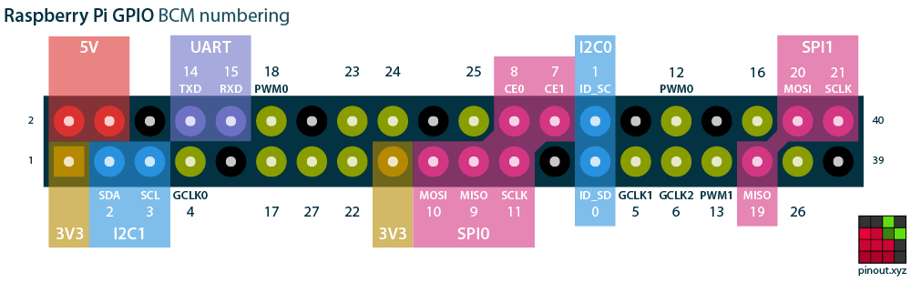
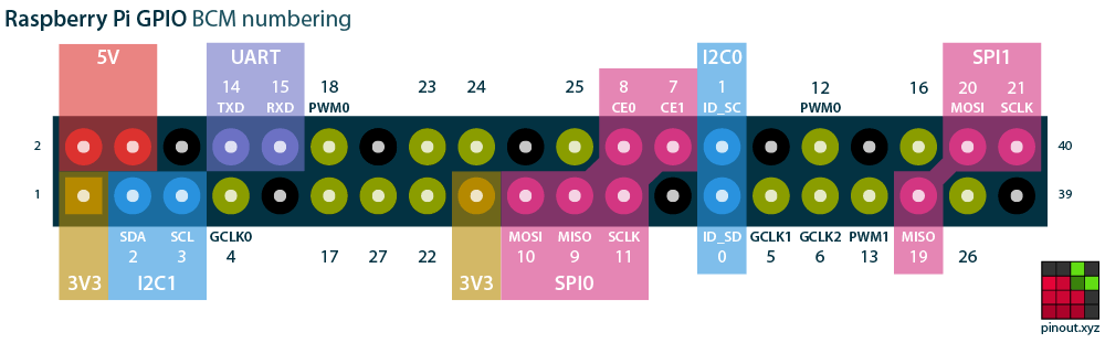
Point is, I2C is only on pins 2 (SDA) and pin 3 (SCL).
A small number of Pimoroni I2C devices use an interrupt on pin 4 (GCLK0).
I've noted on Discord that this idea of "breaking out" pins on boards has apparently confused quite a few people.
short drift
the pinout diagram of the HP4 says pin 13 is used for one of the six green bits.
is possible for me to plug a rotary encoder into the cyberdeck's right-side port (also labelled pin 13) and have it be a responsive input, while also getting that green data to the display?
(i realise this would be easy to test with a very cheap component if i had one already, but vaccination rates are very low here in japan, so i don't want to go into the city unnecessarily, and postage is slow)
faint sparrow
Rotary encoders aren't i2c .. for that you'd need a translator board that does i2c.
Adafruit started carrying one quite recently, iirc.
The SAMD51 has an internal rotary encoder peripheral.
Looking at the datasheet is informative, as it outlines what you might want from such a peripheral.
afaik RPi 3B has exactly one i2c port.
(and one USART port)
hardy plaza
faint sparrow
Rotary encoders aren't `i2c` .. for that you'd need a translator board that does...
There are Breakout Garden I2C rotary encoders that use a Nuvoton microcontroller and RGB LEDs on the transparent knob. Perhaps that's the ones meant.

Add a colourful light-up dial and spin your Raspberry Pi project right round!
 trim pond
don't really need help just a opinion, I am used to running the lite/no desktop env builds of linux as a whole but I always do so with my older pi 3 b+ to give it all the resources I can as I would hit the limit too quick, I have 3 of those and have for years... just got a pi 4 with 8 gigs and unsure how much more the "complete" os package adds on and if its noticably taxing when running things like a database as well as web services etc. I had to have a pi for my db, a pi for my bots, a pi for rest and my iot service etc before due to low performance or inability to due to ram limits (my DB)
I don't want to spend a bunch of time setting it up and just end up rolling back to lite XD
any input would be nice, please @ me tho
also is it worth it to install 64 bit raspbian? I think I need to for my DB but I don't know if there are too many issues
hardy plaza
trim pond
don't really need help just a opinion, I am used to running the lite/no desktop ...
I don't think the 32/64 bit issue gives you any performance break at all unless you're using software that can take advantage of it. The 64 bit OS is to my understanding necessary for the Pi 4 to be able to access the upper 4gb. As for performance of a Pi 4 vs. Pi 3 B+, it's certainly a faster CPU but really that much. The Pi 3 B+ is a four core 1.4GHz, the Pi 4 a four core 1.5GHz CPU. The biggest benefit of the Pi 4 is the increased memory, since running things in memory is a lot faster than off a drive, particularly an SD card. I use a Pi 3 B+ with a Samsung SSD and get pretty good performance and a ton of storage space.
Oh, and the Pi 4 has USB-C, which depending on your application could make a difference in IO speed.
trim pond
ahhh thank you, , my concern for the 64 bit thing is from a lack of support for 32 bit for mongoDB and other tools I use, you can install legacy options but..... yeah.... so I am going with the 64 bit, i SUPER appreciate the info on the ram as well
trim pond
hardy plaza
I don't think the 32/64 bit issue gives you any performance break at all unless ...
thank you
hardy plaza
trim pond
ahhh thank you, , my concern for the 64 bit thing is from a lack of support for ...
If you already have access to a 32 bit Pi then I'd try out the installs first. Things might work fine, dunno, but it'd cost nothing except a bit of time.
trim pond
I was setting up my pi 4, already doing the 64bit full release, I think if i have a problem I will try and just opt into CLI mode if that isn't buggy
i want full access to my 8 gigs XD
still notch
I am using the command:
raspivid -o - -t 0 -b 1000000 | ffmpeg -i - -f s16le -i /dev/zero -c:v copy -c:a aac -g 50 -f flv -flvflags no_duration_filesize rtmp://a.rtmp.youtube.com/live2/[YOUTUBE LIVE KEY]
To YouTube Live Stream.
This works for a few hours then stops.
I am searching for advice on why this would stop as well as ways to best debug
Since the command failed after 5-7 hours, I tried starting/stopping/restarting with the command wrapped within a bash shell, then using a cron job.
bash shell:
#!/bin/bash
sudo pkill -9 ffmpeg
sudo pkill -9 raspivid
echo "---------- "
echo "*****>>Starting birdcam service at $(date)" >> /home/pi/birdcam.log
raspivid -o - -t 0 -b 1000000 | ffmpeg -i - -f s16le -i /dev/zero -c:v copy -c:a aac -g 50 -f flv -flvflags no_duration_filesize rtmp://a.rtmp.youtube.com/[YouTube Live Stream key]
cron job:
@reboot sudo /home/pi/birdcam.sh
*/10 * * * * sudo /home/pi/birdcam.sh
Using this method, the Rasp Pi / Zero W freezes after about two hours.
As with #1, I am searching for advice on why this would stop as well as ways to best debug
OR
Is there a better way to stream to YouTube from a Rasp Pi?
Thank you.
fresh patrol
trim pond
I don't want to spend a bunch of time setting it up and just end up rolling back...
If you know what you want I'd start with lite and install any extras rather then installing the full enviro
faint sparrow
You can just get to the command line in Raspberry Pi OS (Raspbian name deprecated since May 2020 or earlier, I just read today ..
.. and remove stuff. That's it. It's Debian.
# sudo systemctl stop unattended-upgrades.service
something like that.
If it creeps back, sudo apt-get remove <offender> prevents it from re-attaching 'somehow' (borgishly).
Not sure on that remove verb. It's purge in dpkg.
So I really don't see any point to installing crippleware. ;)
(or really anything but the convenience of 'this one closest match to what I wanted' and then tailor it further)
I thought the Raspbian Buster Lite SD card from afruit was neat because hey it was running as soon as I applied power.
🛩️
I'm trying to decide about 5V power for the rpi4.
What I really want is a SPST switch that, when thrown, brings 5VDC to everything in my project at the very same instant.
What I do not want is to power all of the project through the two corner pins of the rpi4 (at 5VDC) for all peripherals that aren't USB-A equipped (like the keyboard/mouse).
So I need a Y-splitter at a minimum on the 5V line; some of which goes into the USB-C connection of the rpi4 (to power it).
I just don't like the idea of using a 120 VAC power strip as my ON/OFF switch for the entire project. A master power switch - at 120 VAC. 'Feels' wrong to me.
I want to switch the 5V line instead. ;)
STM32F407 Discovery, Lumex 96x8 RGB array are the two primary power consumers of the project, besides the RPI4 itself.
The RGB seems to reliably pull less than 850 mA. Sometimes less.
The STM32 Discovery, I'd credit it to say 75 mA (maybe much less).
fresh patrol
You need one of these eh
 faint sparrow
Adafruit HDMI to VGA dongle also. ;)
I think what I need is one of those Mean Well 35W DC PSU's for 5.1 VDC and deal with the consequences of using one.
I'm pretty sure I'm going to use Anderson PowerPoles for the interconnects outside the project chassis. qsradio.com or somesuch has them.
I've already got the Adafruit distribution bus (x2) and it turns out it accepts unmodified banana plugs. ;)
Kinda destroys them, though, I think
(thought I saw one shred when I turned the setscrew ;)
Simple solid hookup wire (esp. on the thick side) is probably most appropriate for that bus.
fresh patrol
I dunno if accepts is the right term. Happens to fit seems more accurate 😉
faint sparrow
;)
I don't get any royalties for each time someone agrees with my use of a given word, so I'm good. ;)
 meager bay
Hey guys! Does anyone know a Pi-compatible low-power speaker? I'm looking for something like a buzzer, but it should be able to play recorded human voices
 opaque wagon
Well, the Pi has a 3.5mm jack which is used to output audio so you can plug basically any powered speaker into it.
The Pi also has I2S, (not to be confused with I2C) which is a "digital sound protocol" designed to transmit audio data between mics, speakers, and microcontrollers/SBCs.
Adafruit has I2S amps, for example:
https://www.adafruit.com/product/3006
(And of course since this is Adafruit it comes with a guide on how to use it with the Pi 🙂)
Then you can wire a speaker cone to it. (ex https://www.adafruit.com/product/1314)

Listen to this good news - we now have an all in one digital audio amp breakout board that works incredibly well with the Raspberry Pi! If you're looking for an easy and low cost ...
meager bay
opaque wagon
Well, the Pi has a 3.5mm jack which is used to output audio so you can plug basi...
Perfect! Thank you. I haven't looked at the guide yet, but I would be able to make it play a number of sound files right? (I'm thinking .wav?)
Was thinking of making a GUI and then have the user select which sound to play
meager bay
opaque wagon
Well, the Pi has a 3.5mm jack which is used to output audio so you can plug basi...
Also sorry one more thing. With that amplifier, is it fine to use a speaker like this? https://www.adafruit.com/product/1890

Listen up! This tiny 1" diameter speaker cone is the perfect addition to any small audio project where you need an 8 Ω impedance and will be using 0.5W or less of power. We ...
opaque wagon
meager bay
Also sorry one more thing. With that amplifier, is it fine to use a speaker like...
That amp can pump out 3 watts at 4 ohms, so I'm afraid that speaker might go 
opaque wagon
meager bay
Perfect! Thank you. I haven't looked at the guide yet, but I would be able to ma...
You can use PyGame to play the sound files - it shows you how to do it in the guide
fresh patrol
It's really common to drive speakers with a larger amp just figure out the max volume where it distorts
 midnight sage
I have a 5.1V 2.5A Power Adapter for the usb power but can the PiZero use this without any damage to the board?
opaque wagon
As long as the voltage doesn't exceed 5.25v, then any (I believe) Pi should be fine. Also if the voltage dips below 4.75v then the Pi may brownout and reboot.
uncut lagoon
i use a 2 amp random cheap usb charger for my pi zero, and it works just fine
midnight sage
I guess use what I have then I'm gonna use a PiZero W to power DreamPi and bring the Dreamcast back online!
restive jungle
Is the raspberry pi 4 schematics open Source
faint sparrow
@restive jungle I've forgotten. Maybe.
This is a location, but doesn't answer the question - not without reading which I have not done:
https://www.raspberrypi.org/documentation/hardware/raspberrypi/schematics/README.md
hardy plaza
midnight sage
I have a 5.1V 2.5A Power Adapter for the usb power but can the PiZero use this w...
Are you concerned about 5.1v being to high or 2.5A being too low? For any Pi, 5.1v is actually the ideal voltage — the official Raspberry Pi power supplies put out 5.1v. As for current, 2.5A should be enough for up to the Pi 3 B+, it'd be plenty for the Pi Zero, which on its own (absent any peripherals) consumes about half that current. You won't damage the board.
I've found that under load a lot of USB power supplies (including batteries) will drop below 5 volts, down to around 4.7 volts, and I've had brownouts or the Pi restarting.
faint sparrow
I do okay with both the 2 A and 2.5 A Adafruit supplies with the rpi3b
PID 1995 - 2.5A and PID 1994 - 2A
I like the 2A one because I can put a switch inline.
The required power is specified there (by RPi foundation recommendation) so that your USB plug-in devices have enough power.
midnight sage
hardy plaza
Are you concerned about 5.1v being to high or 2.5A being too low? For any Pi, 5....
It's the amps im gonna make the pi zero W as a gateway for Dreampi
faint sparrow
I found a 'railway' DC to DC converter on DigiKey that puts out 6A 5V from a 9V - 36V input.
(they have cheaper ones than the one I'm looking at, as well, in the same output and input range)
(and they also make them with commercial AC power input)
Still trying to decide what I want - will probably use a heavy brick supply to bring 12 VDC to a DC to DC converter that puts out 5V at 6A.
(from 12V in)
The other choice is to go from (in my instance) 125 VAC directly to 5VDC.
Pretty sure if all else were equal I'd rather lead into the chassis with 12VDC rather than 5VDC.
Which would force the 12V to 5V conversion, inside the chassis.
The project is an RPi 4B 4GB with Lumex 96x8 RGB display (800 mA) and STM32F407 Discovery board - all want 5 VDC.
I want one master power switch for all of that - so that everything is powered at once.
The inrush is 24V 20A! on the dc-dc converter. It has some inrush provision on the output as well, I think.
hardy plaza
@faint sparrow if you have a link to that DigiKey product I'd be interested, thanks
Pololu has a whole selection of step-up, step-down, and step-up/down converters but not up at the 6A level.
faint sparrow
That's the pricey one. The base model was about 23 bux but not 'railway' certified.
I think there may be one even cheaper without a chassis.
picker uri here:
https://www.digikey.com/short/8qnw503r
hardy plaza
Ah, that explains the 6A: it's quite sizeable. For a small robot, anyway. But still looks good, thanks!
faint sparrow
Scroll way over to the Current Output column and keep an eye on that. ;)
hardy plaza
Yeah, their site is good, even permits sorting by column.
faint sparrow
Yeah I sort by price low to high then scan for the most important thing (in my case - power out in Amperes)
That particular PSU's datasheet shows a few ways to interconnect two PSU's together.
(You can double the voltage in one of those)
hardy plaza
I do find it somewhat a shame that "5.1v" is not a thing, except from RPi. As even good quality 5v supplies often dip below 5v when under load. I've got a 5v 14A adjustable supply, a good one, and I have to have the adjustment set at max just to get a reliable 5v under load.
So I'm now considering buying a proper bench supply.
faint sparrow
5V 18A out:
https://www.digikey.com/short/vq0rdfvd
(9.5 - 18V in)
Those are 37 bux - if they have a 'railway' version it'd be a bit higher priced.
I want about 5V 9A capacity. ;)
(and use maybe 3-4A of that)
The railway one I showed earlier does NOT have a 5.0 V adjustment to bring it to 4.9 or 5.1 say.
hardy plaza
These look suspiciously like my 5v 14A supply, could be OEM'd from the same company. For on-board the robot the smaller Pololu ones will have to do though, my robots aren't that large, except for that neighborhood-sized one I plan to build to conquer the world.
faint sparrow
My guess is pretty simple: a large enough steady current supply can handle a very short current demand.
I don't really know what current inrush protection does/is.
hardy plaza
yeah that makes sense
faint sparrow
Just that it's been under discussion for decades - is a well-known thing.
hardy plaza
It might be a way to sell power supplies.
faint sparrow
The railway version I cited says it puts a resistor inline and then bypasses it with a MOSFET once the switching supply is fully operational.
hardy plaza
What do they call that? A macguffin?
hardy plaza
So the MOSFET would have to be pretty sizeable.
faint sparrow
So let's just say you have a black box that supplies the DC to DC converter and the black box 'always provides the right things'.
hardy plaza
Yeah, McGuffin without the 'a'
faint sparrow
You would still have to deal with current inrush in the final stage (12VDC in to 5VDC out).
hardy plaza
It's got to be at the very end of the stages
faint sparrow
I'm guessing this protects 'downstream' equipment from a surge.
hardy plaza
Does your application require such a thing?
faint sparrow
But what if the 'black box' feeding the converter is already online and providing input voltage at the proper current capacity, and you add SPST to interrupt it?
hardy plaza
I'd think this only applies if you're pushing your supply towards its limits.
faint sparrow
I want to overbuild to learn what each thing does and is about.
hardy plaza
Then the SPST stops flow at that point. Hmm. You worried about damage then?
faint sparrow
Yeah my thinking is that at 80 percent load it's a different story than at 15-22 percent load, which is where I'm targeting.
I think I'm primarily worried about 'noise' and you know speaker pops.
Non-damaging transients.
hardy plaza
ah
faint sparrow
That might either make the audio unpleasant, or glitch a microcontroller that's starting up.
hardy plaza
Most of my guitar pedals pop on and off and I have to "fix it in the mix".
faint sparrow
I don't know I'm just wild-guessing it here.
If it doesn't cost too much to implement and it has a measurable difference, I might want it.
hardy plaza
I have found that on some of those pedals, if I give them their own supply (knowing they are power hogs) their clicking goes way down in volume.
faint sparrow
I don't want to have to build a second one with corrections of errors noticed while building the first one, if I can anticipate far enough ahead.
hardy plaza
So you're likely on to something.
faint sparrow
Well this is sort of the opposite: I want to avoid any 2nd source of energy, and have one master power supply /sauron
The final voltage is 5V as that's what the entire project wants.
hardy plaza
But if it's an audio application I thought having both a high- and low-capacitance load would both stabilise and high-freq filter the supply.
faint sparrow
(It's not an audio application; that was just to field your question with a f'rinstance ;)
hardy plaza
Understood
faint sparrow
squelch on modern radios is terrible, usually.
Just horrible.
I've had modern radios that gently raised the volume when the squelch opens; most just BANG open it wide with no ramp-up.
hardy plaza
It's kinda amazing how "modern" technology seems to have been a very large step backwards in many ways, particularly in audio.
faint sparrow
Super annoying when you monitor for a long period while doing other tasks.
It's modern but it is less expensive to make and to buy.
And it's not as good in some small way, here and there, as you noted. ;)
hardy plaza
I can't even buy a good quality stereo except by spending many 1000s from a specialty audio store, when I used to get that same quality on pretty much any product in a department store.
faint sparrow
But if you grew up with better user experience, that's your standard, and the modern stuff often doesn't measure up.
so anyway, help with raspberry pi ;)
The power supply project's project that I'm working on is rpi4 based - just got the rpi4 in the other day - never owned one prior.
hardy plaza
RPi4 based? A power supply? For a Pi or using a Pi?
faint sparrow
I corrected that. was worded confusingly.
It's a power supply project's project. ;)
faint sparrow
(the new power supply project will power an existing project with an unsatisfactory power arrangement involving multiple 5V sources to carry at capacity)
Mine seems fine at the aluminum case level. Not warm to the touch.
(no heat sink contact so who knows how hot those chips are getting)
hardy plaza
I won't use one on a robot only because I don't need that kind of processing power and the battery life would plummit. But they are for CPU intensive tasks a lot faster than the 3 B+.
I've got the all-encompassing aluminum case. It stays pretty warm. Maybe not "hot" exactly.
faint sparrow
I only got it to keep up with the Joneses. The Joneses are developing mostly for rpi4, I'd guess.
I got the new anidees case at afruit store
hardy plaza
I put one of those tiny fans nearby (aiming across the board) with a Python switcher for the fan based on CPU temperature. It's pretty amazing how much one little fan can do. All those silly copper pipe and RGB LED coolers seem pretty unnecessary but I'd not want to tell the boys that...
Do you like the case? I've seen that company's cases around for awhile, looks like a pretty high-end nice looking one.
faint sparrow
I'm not going to cool this project with any fan. Got enough electric motors running nearly 24/7 here as it is (refrigerator especially).
I love that case.
I don't love the price. Case: yes.
It's nice.
You can't PiUART it because there's no hole there.
hardy plaza
Well, the little $1 from China fans I'm using don't even make enough noise to hear them, but seem to work pretty well.
faint sparrow
You'd be drillin' aluminum to change that.
hardy plaza
The top is plastic isn't it?
faint sparrow
perspex I think the brits call it
we called it plexiglas here iirc
whatever we had in the 1970's in industrial arts class.
Very thick.
hardy plaza
Could drill two small holes with a bigger one in the middle for a fan, but I can understand not wanting to risk it.
faint sparrow
begins with an 'A' the word I can't think of. Maybe acrylic.
faint sparrow
In contrast, the adafruit all weather boxes definitely polycarbonate stuff like food grade plastic.
drills very differently, I'd say.
hardy plaza
Yes, very much so.
Acrylic tends to crack very easily.
I use Delrin and it cuts like butter.
faint sparrow
Yeah this stuff looks like it wants to crack if you tighten the screws too far.
I have a ham antenna center thing that's made of delrin - supposed to be good with RF
(painter's pole adaptor for a Buddipole center feedpoint thing)
hardy plaza
The little Zumo robot uses 2mm acrylic for the top plate over the battery compartment and even the smallest stress will crack it I found out, sadly
Delrin is extremely tough. I use 3mm black Delrin for my robot top plates.
In all the cutting and drilling I've done over the years I've never had Delrin crack.
But as regards your power supply, are you basing it on an existing schematic with a the power conditioning?
faint sparrow
@hardy plaza The Lumex 96x8 RGB array (3mm pitch) supports a USART interface (STM32 daughterboard included). Runs on 5VDC and signals at 3 VDC.
I have it separately powered with a tablet USB-A 5V supply.
It's been backfeeding STM32F407 discovery through the USART connection.
That's the beginning.
I could just put 10k inline with TX-RX and RX-TX and probably be done with it. ;)
(I can tell the Discovery is backpowered because an external LED I use for blinkie lights up as soon as I cut power to the Discovery but not to the Lumex)
So my brain says master power switch as the obvious solution.
That way when one has its power cut they all do.
hardy plaza
Like a stock ticker display, yes. Do they provide any interface or programmability on the STM32 or is it fixed/closed firmware?
faint sparrow
rpi4 provides tty interface (like an xterm running minicom, say)
You can't reprogram the Lumex daughterboard. Not without reverse-engineering it, or maybe digging a lot deeper than I have.
Seems barely adequate (Hayes instruction set).
atef=(1) I think is one of them.
hardy plaza
Ah. Was only dreaming of my long-sought-after I2C master-slave functionality, which happens to be implemented on the STM32.
faint sparrow
gotcha. ;)
No mecrisp-stellaris (prominent Forth implementation) has no i2c at all for the STM platform. Someone did implement SPI though.
hardy plaza
Nice specs at: https://www.lumex.com/spec/LDM-968-P3-UR.pdf
hardy plaza
I was trying to encourage some boys on a different channel to take up Forth... 😋
faint sparrow
;) I keep working on new entry-level basic Forth implementations.
My favorite lately supports flashROM on RP2040.
hardy plaza
Not a cheap display at NZ$128. Looks quite nice though.
faint sparrow
I think it was USD $79 over a year ago but not 2 yrs ago.
hardy plaza
I downloaded a Forth implementation written in Python. Thought the integration might be interesting.
faint sparrow
Ting rewrote a recent javascript forth that's very interesting.
hardy plaza
Sadly, living in NZ $128 feels pretty much like US$128.
faint sparrow
they're up to USD $85 now. Lumex 96x8 RGB
It was either that or do an elaborate chassis wiring job for discrete monochrome LED's. Lots of them.
hardy plaza
You apparently have the need for one.
faint sparrow
(which I'd rather have, overall)
I was just lazy.
I also like the USART interface more than I supposed before I bought it.
hardy plaza
I'd frankly not want to solder that many LEDs, and you'd likely find a few didn't have the same display brightness.
faint sparrow
I wanted octal bit-level data input in groups of 3 SPST switches, lots of them, to do front panel programming.
I figured my fingers would get sore and I'd wonder why I did such a thing. ;)
hardy plaza
I still have this dream of a small PC board project that would be a bunch of SPSTs and LEDs, to emulate the front end of an Altair/IMSAI kind of computer, that would a simple hardware interface to a Pi or microcontroller. So people could emulate working on an early 70s computer.
...not enough time for frivolous exercises.
faint sparrow
Exactly.
That's pretty much what I have in mind.
I want it a reasonable time investment and reasonable use out of it.
I should probably polish my binary input routines in Forth and use a regular keyboard.
2 BASE !
001 110 021 <press ENTER>
ok
like that. ;)
We used to setup a boot program that way on an old piece of gear.
When you pressed the RUN button, it read in punched mylar tape with the real program on it.
So that's all I'm really doing.
The STM32F407 Discovery gets power from the RPi4. From it's PSU (factory PSU recommended, 3A 5.1V).
The Lumex has its own PSU.
I just want a power bus for all of that - one that will satisfy my aesthetics I guess you could say.
I don't want 120 VAC lead-in through the chassis - has to be 24VDC or less. ;)
hardy plaza
Yeah, I've stayed away from any 120 or 240 (here) anywhere near my hands.
faint sparrow
;) Well I don't mind opening a chassis that was built in a factory with those voltages.
I just don't want to design one.
hardy plaza
agreed
faint sparrow
I figure the thing that plugs into 120 VAC should have a UL sticker on it (USA-centric view).
My ham transmitter (DX-60B) had high voltage in it. The tubes (6146-B's) were in a cage.
hardy plaza
We've been talking power supplies, I have this in my shopping cart: https://www.aliexpress.com/item/1005001679200352.html?spm=a2g0o.cart.0.0.732e3c00sTkpen&mp=1

aliexpress.com
Smarter Shopping, Better Living! Aliexpress.com
faint sparrow
;)
I have a 12V 12A bench PSU - just a Pyramid (probably designed to run a car stereo on the bench).
I had an Astron 35A 12Vsupply but gave it away.
That thing really made a sound when you threw the power switch. K-chung!
hardy plaza
The benefit of one of the linked ones is current limiting.
faint sparrow
Yeah current limiting (selectable) would be super nice to have.
The railway supply I looked at (linked above) has current limiting at a fixed point.
hardy plaza
Especially in robotics when I'm not sure I'm going to blow a motor or something.
faint sparrow
(basically to prevent you from going too far on a current draw; probably due to an unexpected fault condition)
hardy plaza
Does it just shut down or actually limit at a fixed point?
faint sparrow
It limits afaict.
hardy plaza
Of course the ability to adjust that for a specific requirement is the bonus.
faint sparrow
So it'd brown out if you count full line voltage at limited current a brown out.
Yeah I would like a front panel control to dial it down to 2A or 3A or 4A depending on what I am expecting.
hardy plaza
I call "brown out" a drop in voltage when hitting a limit.
faint sparrow
;)
hardy plaza
Isn't that what happens to cities when the air conditioning gets too much?
faint sparrow
I think so yeah.
hardy plaza
Like the whole grid drops below 110v
faint sparrow
The pole transformer local to our homes provides the step-down from the Primary.
hardy plaza
Yup. I've got an undeveloped property that if I want to build I've gotta come down off of the high voltage lines myself.
faint sparrow
If you back fed the system from your house, the transfomer would step it up and energize the Primary, which is why you have to be super careful not to do so.
At my house the line voltage is a bit high at 125 VAC (on some days).
If everyone runs their air conditioner it probably drops to 122 VAC (just a guess).
'everyone' is 3-4 households I'd guess.
I would think a system-wide brownout would mean the Primary itself drops.
Maybe from (say) 7 kilovolts to 6.2 kilovolts.
The pole transfomer works by ratios of wire turns, afaik.
hardy plaza
Still enough to fry a banana at a few feet.
faint sparrow
So the ratio would be constant; the voltage on the output would track (drop) from the variance on the Primary.
The power companies put out YouTube videos on this.
hardy plaza
You're starting to sound like someone with a background in power engineering...
faint sparrow
Otherwise I'd not have repeated it here. ;)
No I am not an engineer. Those folks know real math!
hardy plaza
heh, agreed.
faint sparrow
I used to think so and even claim so until I bumped into qualified people.
hardy plaza
I've had all the math courses for an engineer but it went right through my head without much effect
faint sparrow
So anyway back on topic ..
I have the 3A RPI foundation PSU - it's USB-C. It's nice.
No complaints.
But I don't want to pull an extra 800 mA through it's pins on the GPIO array (in the corner, those two 5V pins).
Right now I'm just powering STM32F407 Discovery off those pins, through a Schottky diode (about 0.2 V drop).
Without the Schottky, the STM32F407 was able to back-power the rpi4 through those pins.
The source was the 500 mA USB-A jack of the host PC - used to update STM32F407 through a separate USB-B jack.
(miniature B - don't remember the exact name - trapezoid shaped)
That gets connected only once a month (or less).
hardy plaza
I think Micro-B. But yeah...
faint sparrow
I was surprised when the Pi didn't go off, after disabling the filesystem (fshalt in 9front.org)
hardy plaza
That RPi power supply is 5.1v so it doesn't dip so far when loaded.
faint sparrow
So I yanked the only possible power cable (USB from host PC to Discovery) which was still connected, and holding up the Pi!
The Schottky, once installed, prevents this condition from arising.
It's a diode-OR arrangement.
faint sparrow
host PC is spec'd for 500 mA.
It was! through an alternate power path.
Host PC @500 mA 5VDC > micro-B firmware port, STM32F407 Discovery > RPi GPIO bus, 5V pin.
That was a continuous path.
I put in a Schottky between the Discovery and the RPi, which is reverse-biased by the above path.
(the host PC sees the cathode of that schottky, not the anode)
This way the RPi can power the Discovery, but the Discovery cannot (reciprocally) power the RPI4. ;)
hardy plaza
Very clever.
faint sparrow
;) it's standard practice really.
hardy plaza
I am being called for lunch! gotta run...
faint sparrow
There's already one schottky diode on the STM32F407 Discovery, which is the other diode in the OR circuit.
take care!
@hardy plaza (I know you're away)
Here's a big factor: with a DC to DC converter, I can obviate a voltage drop from the 120 VAC source, to the chassis .. as the DC to DC converter accepts a wide range of voltage inputs, without adjustment.
So it's automatically compensating for low input on a continuous range of voltages (not stepped at all).
The output circuit (5V 6A) is less than ten inches to every load in the chassis, and is hardwired.
So that's going to be very predictable voltage to the consumers of power.
Whereas if I go direct, 120 VAC to 5VDC @6A I incur losses from the output of 5 VDC to the chassis entrance, which may be 6 feet (two meters) away .. or more.
Plus if I start low (4.93 VDC) and use an interconnect (non-permanent connection at/near the chassis boundary) I may drop some small amount of voltage.
Eating into the margin remaining.
Could be the difference between having enough headroom for, say, an inline diode, or not.
hardy plaza
I've been generally thinking 12v to the edge of the Pi, then 5v on the board.
midnight sage
So how does the Pi Zero W connects to a BT Keyboard?
cold monolith
midnight sage
So how does the Pi Zero W connects to a BT Keyboard?

CNET
The Raspberry Pi 3 comes with Bluetooth 4.1, but it doesn't work out of the box. Here's how to get Bluetooth up and running on the latest Raspberry Pi.
Should be the same as that, it also uses bluez and the gui util if using a desktop
midnight sage
Well Dreampi doesn't have a GUI its all CMD based to setup everything
midnight sage
I might do some tricks to the cmdline.txt and get it setup on boot so I can get it running through its cmdline
pliant pebble
If your RPI is super slow, try updating the SD card to class 10. I updated from class 7 to class 10 and it made a world of difference.
Not pertaining to any conversation, just throwing it out there 🙂
hardy plaza
pliant pebble
If your RPI is super slow, try updating the SD card to class 10. I updated from ...
Yeah, and leaving /boot on the SD card and moving / over to an SSD will give you an even bigger boost.
 wheat pasture
I recently got a Rpi400, a hyperpixel 4 and a cyberdeck HAT to put it all together as the Cyberdeck Hat has the HyperPixel 4.0 on the list of recommended displays.
I am not sure whom to ask/tell but after doing some troubleshooting these two do not work together?
After installing the drivers (using the Buster with desktop) the screen would power up and show for a couple seconds then turn black with only the back light on. I did some tracing and discovered that on connector #18 the (zener? 0.7v foward / 3.0v reverse) diode is connected to GPIO 12 that is the LCD Chip select for the HyperPixel. I removed this diode and the display works well.
Or was there sone super simple software thing I failed to do 😣
 steady rose
@wheat pasture thanks for sharing those details. that's helpful information.
pliant pebble
hardy plaza
Yeah, and leaving `/boot` on the SD card and moving `/` over to an SSD will give...
I haven't tried that. Thanks!
meager bay
Will a Pi Zero W be able to control a stepper motor, a speaker, some LED strips, and a camera? External power supply is included of course.
lost wolf
meager bay
Will a Pi Zero W be able to control a stepper motor, a speaker, some LED strips,...
As long as everything is being powered properly, yeah that should work. It has enough pins. The LEDs will want to be powered separately (though you can power from the same source if you mangle a USB cable and hook it up to a 5V power supply with enough juice to handle everything else too).
meager bay
lost wolf
As long as everything is being powered properly, yeah that should work. It has e...
Thank you. I plan on stepping down the 12V for the motors to 5V for the LEDs. This would be good right?
lost wolf
I'm not super familiar with motors, but that sounds like it should work. I would research it a little before saying yes for sure.
I deal with microcontrollers more than RPi, but the concept and logic is the same.
meager bay
Sounds good thank you. Also, do you know if it would be possible to make a separate Pi device that will act as a remote for the main device? I know with STM32 you can have two transceiver modules 🤔
lost wolf
That one I'm unsure of entirely. Hopefully other folks can help you out there.
hardy plaza
meager bay
Sounds good thank you. Also, do you know if it would be possible to make a separ...
There are various ways of creating a master slave such as I2C. The Pi can certainly act as master but you’ll have to research which microcontrollers and which languages support slave mode
meager bay
hardy plaza
There are various ways of creating a master slave such as I2C. The Pi can certai...
Thanks! I'll see if I can do that with two Pi Zero W
odd panther
Hello, I wanted to get some insight on an issue I am having with a program. Program takes accelerometer data and writes it to a file, which is controlled by 2 buttons.
Button 1: Takes indefinite number of samples until button is pushed again.
Button 2: Takes finite # of samples.
After both cases it should re-loop.
Functions run normally when ran through terminal. However, when I try to implement it so that it runs on pi boot-up through Bash Script, Button 2 works as normal, and Button 1 will start but cannot be stopped with the second push.
#!/bin/bash
cd /home/pi/Desktop/lis3dh-spi-linux
python3 start.py
maybe try and write print statements to a text file and see where it stops working?
short drift
wheat pasture
I recently got a Rpi400, a hyperpixel 4 and a cyberdeck HAT to put it all togeth...
Hey, I have the exact same setup, and never had to remove any diode.
wheat pasture
short drift
Hey, I have the exact same setup, and never had to remove any diode.
hmm interesting, with the diode in place the screen will boot then go blank a couple seconds later. I think two other people had this problem too from a reddit post I was reading. Maybe something is trigger that pin? I am using the github repo for the drivers
The thing is if you use straight cables or plug in directly into the Pi there is no problem at all
short drift
I've used a ribbon cable and also the cyberdeck hat, both ok. Because it's a 400, it doesn't really fit directly.
short drift
(Well it might, but it would be facing away from the keyboard, so never actually tried checking if it even fits.)
steady rose
@wheat pasture @short drift this issue has been coming up a lot. seems to be very marginal and thus hard to repeat. this thread is probably the most active:
https://forums.adafruit.com/viewtopic.php?f=50&t=179733
and we've suggested the fix proposed by @wheat pasture there (thanks again for the info). will be interesting to see what others report back. it could be that the diode is causing issues with the LCD CS signal in some cases? (still TBD)
short drift
I'm also on pretty vanilla raspbian and pimoroni's provided hyperpixel software, like avakato seems to be.
That bug does indeed seem like a hardware issue. I wonder if it varies by manufacturing batch, (and if so, batch of pi 400, adafruit cyberdeck hat, or pimoroni display?)
wheat pasture
short drift
I've used a ribbon cable and also the cyberdeck hat, both ok. Because it's a 400...
Curious which hyper pixel do you have? The rectangle or square one because the rectangle one fits really nicely with the Pi400 with cyberdeck hat. I’m really surprised how crisp this little display is given the resolution
yeah I attached the hyper pixel directly on the Pi400 to test. It attaches facing away and you need the header to make it even connect. I’d be curious to know what part of the hardware chain is causing it since it’s working great for others.
wheat pasture
steady rose
<@!181998109633675274> <@!217632238194524162> this issue has been coming up a lo...
You’re welcome, I hope your team gets to the root of this and fixed for others. I am really enjoying this little setup. One other person on noted that this fix worked for them https://www.reddit.com/r/cyberDeck/comments/nfhcxw/help_with_cyberdeck_hat
short drift
wheat pasture
Curious which hyper pixel do you have? The rectangle or square one because the r...
rectangle! in cyberpunk mood here.

(that's on a normal ribbon cable, before the adafruit cyberdeck hat was back in stock)
wheat pasture
Oooh i like it!
short drift
cool-retro-term (swordfish90 on github)
it's a qt terminal which does all kinds of green phosphor, amber phosphor, curved glass screen, crt speckling effects, et cetera. fun for pictures!
wheat pasture
oh neat, thanks! I'll check it out, I want the amber look
trim pond
anyone know if there is anything out there for a project to use a pi to read a car computer port to get your current speed etc?
if so please ping me
pliant pebble
I know this is a super noob question, but how do I build a tar.xz file on Raspbian?
It's a ARM build of sublime text.
hardy plaza
pliant pebble
I know this is a super noob question, but how do I build a tar.xz file on Raspbi...
sudo apt install xz-utils
pliant pebble
hardy plaza
sudo apt install xz-utils
Cool, thanks 🙂
trim pond
I seem to be in a bind now.... might have to re start my project but thankfully I log each step I take.... but I think PM2 for launching node/npm instances on startup took down my pi4
pm2 save```last two commands sent out and restarted
and I had restarted just prior to this, this run was only for getting pm2 up and running
seemed fine too
I did set the startup to wait for network before
before rebooting I was able to see the site as well
I am also using the 64bit image
last things and after that no restart connection will work

I don't understand.... I have my pi downstairs, I have been ssh'ed into it, I pick it up, turn it off and on a few times, take out the card put it back in turn it on and off again 2 more times and now it works...
trim pond
if anyone knows a way to have ffmpeg launch at startup with a delay I would appreciate it, I made a systemd call to a .sh file that hold the command but its launching too early and that makes it fail as nginx isn't ready with the rmtp server yet
id imagine a 3 minute delay would be perfect... unsure if I can use systemd this way
uncut lagoon
you can just start the script as a background task inside ~/.bashrc, and in the script you give it a sleep or something, and then it runs the command(s) you want
trim pond
thank you, I currently have a .sh file but wasn't sure if I should sleep it there or not as I don't know if that would halt the other startup services
ill look up setting up background tasks like that
uncut lagoon
if it is started as background, it wont matter
it's just a simple sh [file].sh & and you're done
but you might want to redirect the output to /dev/null or something
trim pond
My code blog... Stuff that I want to share and not forget.
found this article is this what you meant? never went about this in this manner tbh
midnight sage
how I get a modem port to work with the Pi Zero W for the Dreampi setup with line inducer
trim pond
# Carry out specific functions when asked to by the system
case "$1" in
  start)
    echo "Starting stream"
    # run application you want to start
    sleep 4m
    /usr/local/bin/startstream.sh
    ;;
  stop)
    echo "Stopping stream"
    # kill application you want to stop
    killall ffmpeg
    ;;
  *)
    echo "Usage: /etc/init.d/startstream {start|stop}"
    exit 1
    ;;
esac

exit 0 ``` I modified the script from that page to see if this would work, if anyone sees anything dumb here lmk X/well I will find out soon
didn't work X/
uncut lagoon
the file is missing a shebang
https://www.shellcheck.net/ <-- you should also try this
ShellCheck finds bugs in your shell scripts
raw solar
shebang?
 finite bay
#!/bin/sh or whatever as the first line
faint sparrow
! << a 'bang'
faint sparrow
faint sparrow
So that's all I'm really doing.
The STM32F407 Discovery gets power from the RPi4...
I ended up cutting the cord of the (new!) factory RPi4 PSU (measures as 5.24 VDC when energized).
Cut it midway and stripped off a good inch to an inch and a quarter of the outer jacket.
That's a nice inner conductor in there; so is the insulation on it.
(both are a silver color)
I had a 3PST laying around so that went inline (switching both + and - .. no real theory there ;)
Now I have a proper external power switch for the RPi4 setup.
raw solar
faint sparrow
` ! ` `<< a 'bang'`
I'm familiar with ! being bang, just hadn't heard shebang before XD shell bang?
faint sparrow
shebang might be US slang
It's almost always "the whole shebang"
kit and kaboodle
finite bay
Wikipedia has the etymology (sort of).
raw solar
I think you mean kitten kaboodle
But yes, shebang in context of "the whole shebang" is familiar, but not in that context
trim pond
I actually had it on there just didn't post the entire top part XD but I saved the link
uncut lagoon
@faint sparrow@raw solarhttps://en.wikipedia.org/wiki/Shebang_(Unix)
In computing, a shebang is the character sequence consisting of the characters number sign and exclamation mark (#!) at the beginning of a script. It is also called sha-bang, hashbang, pound-bang, or hash-pling.When a text file with a shebang is used as if it is an executable in a Unix-like operating system, the program loader mechanism parses t...