hmm, google is giving me two possibles (without knowing more context or having it fail on mine) - a realtek driver update being needed (which is always a good thing to check I guess?) and also trouble with the USB nic having issues when connected to a HUB that doesn't fully support it
The driver bits all pointed to the NIC never getting into full-duplex mode, so that may be a red herring
The USB hub issue seems more promising - you may want to read this thread to see if it matches your seen behaviours
https://forums.raspberrypi.com/viewtopic.php?t=359625
#help-with-linux-sbcs
1 messages · Page 8 of 1
 north mantle
that thread leads to a github issue which, from the scan I did, offers a solution - https://github.com/raspberrypi/linux/issues/5753
 snow timber
that does look like the issue and will see if it "works" moving the usb nic to usb2.0, but the "fix" mentioned looks to be for raspberry pi os (rpi-update not installed or found from Ubuntu 23.10) 😦
Connectivity seems to work via either onboard nic or usb3 (1gb) nic, but usb nic disappears during a file copy across it (so not sure if it's nic compatibility or os and new pi5 chip handling)
north mantle
yea, that's why I was leaning towards the referenced github issue - seems to be a lower level driver issue with some hubs
very annoying to debug that's for dang sure
snow timber
re-watching Geerling's video on the pi5 (to see if wifi goes through the rp1 chip? ) maybe see if it's just able to overload bus with usb3 speeds or ?
north mantle
yea, his channel may be a good place to drop a question - he has amazing hardware notes on using/abusing Pis for use
snow timber
I seems at least the 1gb onboard nic, usb3 and usb2 do
 junior edge
So Im trying to use CircuitPython with a Pi3 and some waveshare 64x32 led panel, running their demo code, and it starts to complain about the displayio module. I believe its installed, just confused why its wining to me since it seems like its some weird issue witht he displayio module
 junior edge
ok so apparantly its some issue due to me using python3.9 and not python 3.10
 zenith crystal
i would recommend checking out the newest learn guide for setting up blinka -- quite a bit has changed especially if you're using bookworm
junior edge
I'm not using bookworm. But I restarted to ensure I followed the guide, and manually installed python 3.10, but now for some reason I keep running into issues of just finding which libraries I need to install. Is there a script that automatically installs the recommended libararies for circuitpython?
junior edge
ok so is there a chance that if you initially plugged in a waveshare 64x32 LED matrix panel directly to the GPIO of a rpi3 incorrectly that it can break the panel? Since mine is not turning on when properly on a matrix adapter board thingy
The only time I've had this panel actually run was awhile ago before I got the bonnet and I got the leds lit up In a strange 20 pixel horizontal line of random colors, where I quickly unplugged as it got really hot
junior edge
ok nvm, I think my problem was that I didnt have my code setup properly for the cheap offbrand hat I bought online
junior edge
nvm that nvm the LED panel is correctly setup in code, I am utterly and entirely confused why the LED panel refuses to show anything although everything is wired correctly
 pale pewter
Has rfkill always been active/enabled on the raspberry pi OS? Or has something changed recently? I've never noticed its alert before.
 pliant cypress
junior edge
So Im trying to use CircuitPython with a Pi3 and some waveshare 64x32 led panel,...
pliant cypress
junior edge
So Im trying to use CircuitPython with a Pi3 and some waveshare 64x32 led panel,...
Having the same issue, if you figure it out let me know!
junior edge
well so far I've gotten a small line of green leds to appear at the bottom right. I think its a power issue as I've been having everything plugged in to a USB bank that is plugged directly into my pc, but the ports are set purely to energy output
but the ports output 12V which should be more than enough for both the LED panel and the pi
pliant cypress
oof, sorry to hear that
Im still stuck on the libraries not working
pretty sure something is broken, as this didnt happen before
I am currently building python 3.11 on my zero 2 w, here's to hoping that fixes it/actually completes
zenith crystal
pale pewter
Has rfkill always been active/enabled on the raspberry pi OS? Or has something c...
what alert?
 placid whale
Hi, has anyone tried does Adafruit_CircuitPython_NeoPixel_SPI work with Blinka in Raspberry Pi?
GitHub
SPI driven CircuitPython driver for neopixels. . Contribute to adafruit/Adafruit_CircuitPython_NeoPixel_SPI development by creating an account on GitHub.
I was thinking would this be a solution to run Neopixels without sudo.
 steady rose
placid whale
Hi, has anyone tried does Adafruit_CircuitPython_NeoPixel_SPI work with Blinka i...
steady rose
placid whale
Hi, has anyone tried does Adafruit_CircuitPython_NeoPixel_SPI work with Blinka i...
yep. should work. the looping video on the guide is showing (a) ft232h (b) itsy bitsy and (c) rpi
placid whale
steady rose
yep. should work. the looping video on the guide is showing (a) ft232h (b) itsy ...
Thanks! I'll try this.
steady rose
placid whale
Thanks! I'll try this.
ping me if it doesn't work. that guide is old enough i'm curious if it still works ok with latest hardware, os, etc. it worked at time of guide writing. 🙂
placid whale
steady rose
ping me if it doesn't work. that guide is old enough i'm curious if it still wor...
Ok. I'll do that!
steady rose
placid whale
Ok. I'll do that!
also - neopixel data pin needs to be MOSI on the pi...not sure if guide makes that obvious. it can't be just any digital pin, since it relies on the hardware spi peripheral.
placid whale
Yes, for me that was quite obvious.
pale pewter
zenith crystal
what alert?
It's part of the login message when I make an ssh connection to the Rpi:
'Wi-Fi is currently blocked by rfkill.
Use raspi-config to set the country before use.'
 ruby night
I have never seen that alert...but I always set the WiFi Country for a new board via the Raspberry Pi Imager before loading RaspiOS to it.
some googling of "rfkill raspberry pi" shows me what I have been missing! Who knew 😉 I only use wifi for my Pi's so I've alwasy configured the WiFI SSID and Country code before using them. I never even knew about rfkill.
pale pewter
Yeah. Turns out to be a nothing-burger 'cause this pi is attached via ethernet. I did try going into raspi-config to set the country code and wifi info, but they didn't stick. Tried that twice. I'm missing something, but since I'm hard-wire attached I'm in no hurry to figure it out. #putItOnTheList
zenith crystal
ah -- i don't have anything hardwired any more (cuts down on the amount of wires running around the apartment for kittens to futz with and/or eat)
 vocal glacier
Hello, is this the right forum to ask about python programming of headless Pis in Visual Studio Code?
vocal glacier
Nevermind, it seems I'm asking the wrong question upon googling more.
 rare leaf
Hi all 🙂
I don't know if this is the right channel to ask since I'd first unsuccessfully posted in the *circuitpython *channel. It's definitely Pi related 🙂
Scenario: I've got a 16-bit Color 1.27" OLED display w/microSD holder from Adafruit here(https://www.adafruit.com/product/1673) and I'm trying to run it on a Pi 3 Model B pinout here(https://pinout.xyz/). I'm done with the wiring(https://learn.adafruit.com/adafruit-1-5-color-oled-breakout-board/python-wiring-and-setup) and I want to write some and run some Python code to manage the display. I know from the site that it uses the SSD1351 driver.
Problem: I can only find C versions of the driver, as well as micropy / circuitpy versions. The official Adafruit guides provide only the circuitpython version and I'm using 'regular' python. Thanks to a redditor, I managed to get everything set up finally as per this guide (https://learn.adafruit.com/circuitpython-on-raspberrypi-linux). I even managed to get the LED blinking by following the guide. Trouble now is that I have the drivers but can't find sample code to test the display and iterate off of. I've scrapped around the driver files and their sample code hasn't worked. I've even tried ChatGPT and its hasn't worked either. That's where I'm at at the moment.
Any ideas? Thanks in advance!
We love our black and white monochrome displays but we also like to dabble with some color now and then. Our 1.27" color OLED displays are perfect when you need a small display with ...

Adafruit Learning System
Big, bright colorful OLED
ruby night
rare leaf
Hi all 🙂
I don't know if this is the right channel to ask since I'd first unsuc...
There are examples later in the same guide https://learn.adafruit.com/adafruit-1-5-color-oled-breakout-board/python-usage
rare leaf
ruby night
There are examples later in the same guide <https://learn.adafruit.com/adafruit-...
wow, Thanks!!! Going to testthese out when I'm back home. will report on that 🙂 tyty
placid whale
steady rose
ping me if it doesn't work. that guide is old enough i'm curious if it still wor...
Well it didn't work correctly. Tested with Rpi 4 Model B with Raspberry pi OS 64bit (Bookworm).
Neopixels turned on, but the color was white (RGB Neopixel).
I tried several things, but couldn't change the color or turn the leds off.
Test code used:
import board
import neopixel_spi
import busio
spi = busio.SPI(board.SCK_1, MOSI=board.MOSI_1, MISO=board.MISO_1)
pixels = neopixel_spi.NeoPixel_SPI(spi, 8)
pixels.fill(0xff0000)
I added "dtoverlay=spi1-1cs" to config.txt
I'll do some more testing next week.
steady rose
neopixel data connected to GPIO20? (SPI1 MOSI)
placid whale
Yes
zenith crystal
placid whale
Well it didn't work correctly. Tested with Rpi 4 Model B with Raspberry pi OS 64...
please see #welcome for how to post code
that aside, where are you setting the size of the neopixel? from what I can tell, you're not giving it the right number of pixels (as a start)
steady rose
can you try default SPI? (SPI0 or whatever)
this is working for me on a pi4:
import time
import board
import neopixel_spi as neopixel

NUM_PIXELS = 12
PIXEL_ORDER = neopixel.GRB
COLORS = (0xFF0000, 0x00FF00, 0x0000FF)
DELAY = 0.1

spi = board.SPI()

pixels = neopixel.NeoPixel_SPI(spi,
                               NUM_PIXELS,
                               pixel_order=PIXEL_ORDER,
                               auto_write=False)

while True:
    for color in COLORS:
        for i in range(NUM_PIXELS):
            pixels[i] = color
            pixels.show()
            time.sleep(DELAY)
            pixels.fill(0)
Ok, thanks. Amount of Neopixels is 8:
pixels = neopixel_spi.NeoPixel_SPI(spi, 8)
placid whale
steady rose
this is working for me on a pi4:
```python
import time
import board
import neopi...
I'll try that next week.
rare leaf
ruby night
There are examples later in the same guide <https://learn.adafruit.com/adafruit-...
so I gave it (another) go and I find that ALL the code is tailored to the TFT / LCD screens (the very first python test script is turning on the LCD backlight). I've adapted the code to my 1.27" OLED by commenting out the unnecessary import (for the others) and setting the 1351 import for my OLED. I left the rest of the code intact but I'm still not getting anything to display.
import time
import busio
import digitalio
from board import SCK, MOSI, MISO, CE0, D24, D25

from adafruit_rgb_display import color565
from adafruit_rgb_display.ssd1351 import SSD1351 # changed this to match my screen

# Configuration for CS and DC pins:
CS_PIN = CE0
DC_PIN = D25
RESET_PIN = D24
BAUDRATE = 16000000 # changed this to match my screen

# Setup SPI bus using hardware SPI:
spi = busio.SPI(clock=SCK, MOSI=MOSI, MISO=MISO)

# Create the display:
display = SSD1351(
    spi,
    rotation=90,
    width=128, # changed this to match my screen
    height=96,# changed this to match my screen
    #x_offset=53,
    y_offset=32, # changed this to match my screen
    baudrate=BAUDRATE,
    cs=digitalio.DigitalInOut(CS_PIN),
    dc=digitalio.DigitalInOut(DC_PIN),
    rst=digitalio.DigitalInOut(RESET_PIN))

# Main loop: same as above
while True:
    # Clear the display
    display.fill(0)
    # Draw a red pixel in the center.
    display.pixel(120, 160, color565(255, 0, 0))
    # Pause 2 seconds.
    time.sleep(2)
    # Clear the screen blue.
    display.fill(color565(0, 0, 255))
    # Pause 2 seconds.
time.sleep(2)```A few questions to get started. Are there any errors reported at the REPL? Can you post a picture of your wiring? No need to tag me, I am not an expert on using these displays. Hopefully someone more knowlegeable can help.
 dusk grotto
Hey, I have a quick question. I turned on my Pi to test something, and it had me log in, which is somewhat normal. When I entered my password, it went to black for a second and came right back to the login screen. So far, I've tried stuff online to bypass the password, and nothing has worked. I have confirmed that it is the correct password because I went into terminal mode by hitting control F2 and logged in that way, and it allowed it. Same user as login screen. Anyone got any tips?
zenith crystal
it sounds like there's a bad X configuration somewhere in there -- you can create a new user from the command-line and try that one to see if it's your user's config or a system config
the obvious question is "did you change anything recently and, if so, what was it?" 😈
dusk grotto
zenith crystal
the obvious question is "did you change anything recently and, if so, what was i...
Not that I recall I turned it on less when a week ago procrastinated something and then just shut it off
junior edge
Hey anyone know how to properly program for waveshare LED panels? I have everything configured properly, and wired properly, but Im seeing no output from the display

 smoky bramble
ok so
how 2 git ARM mali gpu drivers
is there something like an apt install mali or something like that?
should i compile panfrost drivers instead?
(open source mali gpu drivers)
placid whale
steady rose
can you try default SPI? (SPI0 or whatever)
I tried this code with SPI0. Neopixel connected to pin19. Still leds just turn white. 64bit Bookworm with Rpi 4
steady rose
placid whale
I tried this code with SPI0. Neopixel connected to pin19. Still leds just turn w...
hmm...lemme boot up the pi4 i was testing with the other day and double check what os, etc. can you post a photo of your setup to check connections, etc.
pi@raspberrypi:~ $ uname -a
Linux raspberrypi 6.1.0-rpi4-rpi-v8 #1 SMP PREEMPT Debian 1:6.1.54-1+rpt2 (2023-10-05) aarch64 GNU/Linux
Thanks for your help!
 steady rose
does your uname output match above?
placid whale
Linux raspberrypi 6.1.0-rpi8-rpi-v8 #1 SMP PREEMPT Debian 1:6.1.73-1+rpt1 (2024-01-25) aarch64 GNU/Linux
placid whale
NeoPixel I'm using isn't Adafuit product. Just a copy of it. https://www.berrybase.de/en/neopixel-stick-mit-8-ws2812-5050-rgb-leds?c=2428

BerryBase
Dieser kleine, intelligente RGB LED Stick mit 8 LEDs des Typs WS2812 kann mit einem Mikrocontroller, zum Beispiel einem Arduino angesteuert…
steady rose
have you tried that with something else? like an arduino board?
placid whale
It could be the problem. They have always worked when using regular Neopixel library.
I have not tested with Arduino, but with Feather they have worked fine.
steady rose
feather and what code?
placid whale
Basically example codes from Neopixel Uberguide
So I haven't tested with spi
Maybe Iäll try that next?
I'll
steady rose
might be due to minor timing differences, but in general, would expect it to work
spi on the feather? could try that as a way to sanity check the timing.
placid whale
Yep
steady rose
what code are you running on the pi?
steady rose
yah, even if number of pixels and pixel color order were set wrong, should still get some kind of activity on the LEDs themselves
might not be correct color, etc., but should light up
placid whale
They light up, but color is white all the time.
steady rose
there's a way to (crudely) adjust timing in the neopixel spi library, if that's needed
steady rose
i'm updating OS right now....in case maybe there's something with that
steady rose
@placid whale how did you get your kernel version to be 6.1.73?
steady rose
oh, nevermind...mine seems to have updated to that after a upgrade and reboot
(blinka) pi@raspberrypi:~ $ uname -a
Linux raspberrypi 6.1.0-rpi8-rpi-v8 #1 SMP PREEMPT Debian 1:6.1.73-1+rpt1 (2024-01-25) aarch64 GNU/Linux
it's still working for my setup though
so doesn't appear to be a simple os / kernel / etc. issue
placid whale
Same code works fine with same Neopixel on Feather RP2040.
steady rose
do they only light up white once the code runs? indicating that at least something is getting output on MOSI
placid whale
All leds light up at once and won't turn off. Only way to turn them off is cutting the power.
steady rose
maybe there's something else using SPI?
placid whale
I'll check
No I didn't find anything from config.txt
This line is activated: dtparam=spi=on
All leds turn on when I run the code, not before that.
steady rose
oh, ok, that's what i meant. just something to indicate the code is at least doing something on MOSI.
do you happen to have a logic probe? like a saleae
steady rose
might even be possible to make one using the feather RP2040
placid whale
I don't have any kind of logic probe. I can borrow a Fluke ScopeMeter from work.
 modest orbit
I have a new PI4 which is all set up with the imager to SD card, and working great. I'm very new to the PI. I've been knocking my head against a brick wall trying to ssh to it from Win10. I've searched and read everything there is about this subject. SSH is enabled on the PI4. All I keep getting when I enter the password (the PI's password) is permission denied, and then Permission denied (publickey,password). Also an message saying
read_passphrase: can't open /dev/tty: No such file or directory
The whole private/public key thing is new to me. I've tried all sorts of things advised online. No luck. Sorry to be such a noob. Thanks.
steady rose
it sounds like the pi is at least showing up on your network?
you were sshing to raspberrypi.local?
modest orbit
Yes, renamed the hostname to pi
My command is ssh pi@192.168.0.xxx then asks for password.
zenith crystal
that's hostname or username? typically the command is ssh username@hostname and i know the pi imager specifically asks for a user name and password (or passphrase)
steady rose
also -how were those set? via the config option in rpi-imager?
modest orbit
Hey guys, forget it - I turned off Auto Login, rebooted, and saw my user name (different than pi Hostname) , so logged into the PI OK, and then used ssh myusername@198 etc from the PC and it WORKS now. Thank you! Man am I a green new guy. 😀
I am happily running a python script on the PI 4 from my PC.
 faint sparrow
Can the Pi5 be configured to fully power off with the "poweroff" command from Raspbian? The command shuts down Linux but does not fully power off the board. This messes with the behavior of my battery pack.
 humble marsh
faint sparrow
Can the Pi5 be configured to fully power off with the "poweroff" command from Ra...
faint sparrow
humble marsh
Is this helpful? <https://www.jeffgeerling.com/blog/2023/reducing-raspberry-pi-5...
humble marsh
faint sparrow
Can the Pi5 be configured to fully power off with the "poweroff" command from Ra...
faint sparrow
humble marsh
Is this helpful? <https://www.jeffgeerling.com/blog/2023/reducing-raspberry-pi-5...
that is helpful, thank you! it looks like jeff's documented fix works for powering off the pi in the way he describes, but I will need to see what I can do with the battery
The Pi and battery bank must be talking via PD or something that gets ignored if the battery is restarted
humble marsh
faint sparrow
The Pi and battery bank must be talking via PD or something that gets ignored if...
you mean the power pack does not come back up when the current consumption is too low? THat is typical for power packs
faint sparrow
The pi5 has to be physically disconnected at the pi and reconnected to get the battery powering that port, even if the battery is already on
humble marsh
there are power packs that do not have that behavior: let me find a post I made recently about that
Power packs that can deal with low current draws:
https://voltaicsystems.com/always-on-batteries/
https://support.anker.com/s/article/What-is-Trickle-Charging-Mode
there are some hack circuits that cycle a power pack at short intervals to keep them on, as well
faint sparrow
humble marsh
there are some hack circuits that cycle a power pack at short intervals to keep ...
thank you- this seems to be something with PD and pins- for example, the Pi shares a USB C splitter with a 4 port network switch. Unplugging and reconnecting the barrel jack on the switch does nothing, but unplugging the USB C side of that same cable kicks on the power supply. Unfortunately the power bank doesn't turn the port on when it is powered on
it's easy enough on my design to pop off the USB C cable though for when it needs to be powered off to save battery, it's just a weird state as I use battery packs more
Voltaic Systems is awesome too- I have a larger V88 or V250 around here, it's just far too big for this build
placid whale
steady rose
this is working for me on a pi4:
```python
import time
import board
import neopi...
I bought a Raspberry pi 5 and the Neopixel spi code works as expected.
Still not sure why it doesn't work on my Rpi 4
 ornate bluff
are the non-wireless versions of the pi zero not produced anymore?
humble marsh
ornate bluff
are the non-wireless versions of the pi zero not produced anymore?
they haven't been produced in a long time. The product is still listed on raspberrypi.com, but not sure how much that means in practice
zenith crystal
general Pi "hat" question for those EE's out there -- if i have a hat on a Pi and the Pi will not power on, the hat is pretty well fried in some form or fashion? (the Pi does power up with a GPIO expander without issues)
 broken shuttle
Depends on what the hat is, but chances are that it's trying to draw more than your power supply can handle (which isn't difficult with a pi).
zenith crystal
an i2c qwiic v2, which doesn't have external power, so yah, i think it's a deader (tbh, this was in a drawer, so...)
 civic trench
@everyone Dear all senior circuit python dev(s), Namaste
I am a java developer, recently switched to AI Python. I am getting a very strange issue, Kindly help me with your valuable suggestions.
I have below modules
Raspberry Pi 4 B+ 8 GB
SSD1306 128x64 I2C
Requirement: I want to display GIF, PNG and Do spritesheet animation on the display with Pi 4.
I have done many tutorials from YouTube, adafruit GitHub but I can find text and statsled tutorial which I am able to do succesfully. I have tried multiple libraries but come to know CircuitPython is best, I could not find no tutorial for display gif or spritesheet. Most of the tutorials belong to Raspberry Pico but I found very less tutorials for Pi 4 still useless, they show only statled. if you can help me by providing some guidance with Pi 4 B+ and ssd1306, it will be much appreciated. I am working on a AI project
Reference - https://www.youtube.com/watch?v=YMGYbmGxhP4
Regards

[Tutorial] How to display Animations on OLED display
⏰ Timestamps
00:00 Start
00:57 Introduction
01:11 Circuit Diagram
01:57 What is CircuitPython
03:00 CircuitPython Website
04:00 Features of CircuitPython
05:49 How to install CircuitPython on RPi Pico
08:30 CircuitPython Development Environment
09:49 Animation Theory
11:00 What i...
 rotund pivot
@civic trench please don't ping roles, and please don't cross-post. this is the correct channel for CircuitPython on Raspberry Pi using Blinka
have you installed Blinka https://learn.adafruit.com/circuitpython-on-raspberrypi-linux
civic trench
@rotund pivot Hi, I am new to discord, earlier I was suggested to post in that channel by bot, they told me to post here. Yes I have installed blinka .. But I am not able to display spritesheet
most of the tutorials are with Pi Pico .. but I have Pi 4B
rotund pivot
the idea of Blinka is that you can use many CircuitPython libraries and example code on a Raspberry Pi
next step is to post your code (see <#welcome message> )
civic trench
Sure, I am doing ..
rotund pivot
displayio is a native module on mircocontrollers, but it's not native to Raspberry Pi
there is this https://github.com/adafruit/Adafruit_Blinka_Displayio/tree/main ...I haven't used it, but maybe someone else has
civic trench
rotund pivot
`displayio` is a native module on mircocontrollers, but it's not native to Raspb...
This is totally correct, I am still looking for the solution.
I am looking for that guy who has used this monochrome display with Pi 4, finding solution for this it is very tedious
rotund pivot
I can't find examples for displayio with Blinka, except for this... https://learn.adafruit.com/running-pyportal-code-on-blinka-with-displayio/raspberry-pi-setup you're not using PyPortal or the PyPortal library, but some of the background might help
the Blinka Displayio library, which is a port of the original CircuitPython displayio library and is built on top of Adafruit Blinka and the Python Imaging Library.
I read those as meaning you'll need Adafruit_Blinka_Displayio and PIL libraries
zenith crystal
civic trench
I am looking for that guy who has used this monochrome display with Pi 4, findin...
if you're using Java, you can use https://github.com/Pi4J/pi4j-v2 or https://www.diozero.com/ (which has a direct 1306 implementation)

GitHub
Pi4J Version 2.0. Contribute to Pi4J/pi4j-v2 development by creating an account on GitHub.
diozero
Java Device I/O library that is portable across Single Board Computers. Tested with Raspberry Pi, Odroid C2, BeagleBone Black, Next Thing CHIP, Asus Tinker Board, Udoo Quad and all Arduino devices that can run Firmata. Supports GPIO (digital, PWM and analog), as well as devices conntected via I2C, SPI and Serial buses.
civic trench
zenith crystal
if you're using Java, you can use https://github.com/Pi4J/pi4j-v2 or https://www...
I can give a try.
ornate bluff
https://medium.com/@awarlt12207/how-fast-can-a-raspberry-pi-zero-2w-boot-8614de1cbd64 anyone know how to reproduce this on the pi zero? I get this error

Medium
Answer: 8 seconds from power to an interactive GUI.
 quasi basin
Hi. I'm trying to configure a vsftpd to work with sftp but if I use the user with sftp it always connects via ssh. I want it to open the folder I specified with local_root
civic trench
Hi Team, I am not able to get the DisplayIO module, how ever I have installed all required packages


any help is much appreciated
 lean kiln
the prompts are using different python environments. In the vscde one run pip install blinka etc
 solemn finch
civic trench
Hi Team, I am not able to get the DisplayIO module, how ever I have installed al...
solemn finch
civic trench
Hi Team, I am not able to get the DisplayIO module, how ever I have installed al...
I think you need to install: https://github.com/adafruit/Adafruit_Blinka_Displayio
 mint berry
Hi all. Trying to see if there's any thing I might be missing. Raspberry Pi 5 4gb, with official active cooler, using the official pi power supply, in the official case (plastic layer with small fan removed to make room for active cooler. ) Running VLC with a 4min 1080p MP4 video on a continuous loop, hooked to a TV in a convention center for 4 days. Approxamitely 8 hours per day. Froze up once on Thursday, twice on Friday, once on Saturday, no times on Sunday but that was only a 5 hour day. After the first freeze on Friday I removed the lid of the case thinking it was blocking the fan. Didn't seem to help.
zenith crystal
mint berry
Hi all. Trying to see if there's any thing I might be missing. Raspberry Pi...
can you ssh to the box when it "freezes"? if so, that if probably going to be your first line of debugging
mint berry
I couldn't ssh into cuz I was working
power cycle fixed it, I was thinking it was just heat,
but it wasn't that hot in there and why would it over heat with all the official stuff
 modern matrix
I've used a Pi 2 for a multi-day convention video loop before; the Pi 5's extra heat/power sometimes complicate things. when it froze, did it freeze mid-image, or blank screen? could be a marginal/failing microSD card, too.
if you're planning to use it for that again, you could run a burn-in test at home, maybe with a keyboard attached, and see if the system truly locks up with no response to local input or SSH.
oh, and depending on how the OS is configured, you may actually have logs from the convention days. check out /var/log and see if the dates on the gzipped log archives are useful. if you didn't have network access or a real-time clock, the dates might be bogus, but you could still look over them for e.g. undervoltage or overheat throttling warnings.
e.g. zgrep -i undervolt /var/log/syslog*
or look through them for reboots and see if you can spot anything amiss?
mint berry
Next time I'll just find my pi 3
 mystic light
anyone know the difference between 2 Rasp Pi Zero 2 SKUs? SC1146 or SC0510?
humble marsh
mystic light
anyone know the difference between 2 Rasp Pi Zero 2 SKUs? SC1146 or SC0510?
This seems to be some internal mfr number difference. The part numbers don't even appear on raspberry.com or raspberry.org. So it may be some kind of inconsquential revision that is not visible to the end user. You could ask on https://forums.raspberrypi.com/
mystic light
obviously the larger number must be better, right? 🙂
humble marsh
mystic light
obviously the larger number must be better, right? 🙂
I think it's newer 🙂
 median sleet

GitHub
Contribute to adafruit/Raspberry-Pi-Installer-Scripts development by creating an account on GitHub.
sudo apt install dkms raspberrypi-kernel-headers ... raspberrypi-kernel-headers is already the newest version (1:1.20230405-1).
$ sudo dpkg -i snd-i2s-rpi-dkms_0.0.2_all.deb
Module build for kernel 6.1.0-rpi8-rpi-v8 was skipped since the kernel headers for this kernel do not seem to be installed.
um.. halp
 velvet folio
I am trying to use a ssd1306 oled display on a raspberry pi in Python. I need a library that will work. The adafruit-circuitpython-displayio-ssd1306 doesn't seem to work and their discussion group suggested coming here. I need some help finding a library/solution that will work. I just want to display 5 lines of text every 5 seconds with several different dynamic text content. Ideas?
zenith crystal
i saw the posts but missed what the traceback error was?
i'm primarily a Java dev, but that does mean I know a bit about threads 😀
zenith crystal
quickie possible pythony pseudo-code:```
def data = []
display = your_display_setup() // init SSD1306 and displayio
start_other_threads(data) // no display stuff!
while True:
sleep(5)
display.print(f"L1: {data[0]}\nL2: {data[1]}\nL3: {data[2]}\nL4: {data[3]}\nL5: {data[4]}")
// end loop
you **may** need to get fancier and put some locks around that data so that you don't get a write to the array when it's trying to printI have a library that works perfectly and is much simplier to use. Thanks
zenith crystal
i see...
 crisp estuary
Hello.
I have an Adafruit FXOS8700 + FXAS21002 breakout from back when they were still made, and was hoping someone would be able to help me troubleshoot by triangulating my observations.
When I wire it up to my Raspberry Pi 4B (ground, 3.3v to the sensor's vin, SDA, SCL) and run sudo i2cdetect -y 1, the sensor doesn't appear; the entire grid is filled with dashes, indicating that nothing is detected. When I disconnect the Pi's 3.3v from the sensor's vin, I get the same results, but much quicker; the sensor is having some effect. The same is observed when I disconnected SCL.
smoky bramble
Just askin', what is the smallest board that can run linux?
 zinc jackal
smoky bramble
Just askin', what is the smallest board that can run linux?
zinc jackal
smoky bramble
Just askin', what is the smallest board that can run linux?
Not sure I'd want to go smaller than a Pi Zero 2W.
zinc jackal
Yeah, the mini is definitely smaller. 😅
Seems rather limited though.. compared to a Pi Zero 2W.
smoky bramble
Yeah, but it made me wonder what was the smallest )commercially available) sbc/linux board
zenith crystal
i think that might be it, tbh -- i have two of 'em and if you remember they're only 2 cores and not the speediest things in the world, they are pretty dynamite
or possibly the compute module, if you're talking "size"
 rugged tusk
After a few short weeks of using raspberry pi 5 and Raspberry PI OS lightdm decided it was time fail.
As anyone encountered this issue. The GUI just stops working. After reinstalling lightdm I get a GUI that doesn’t look like the default raspberry pi os gui. Just some broken icons and large trash can. Smh at this rubbish. Any thoughts would be greatly appreciated
zenith crystal
that sounds like you may have a bad disk? are you using the pi imager app?
rugged tusk
Yes
mystic light
Quality brand SD card?
humble marsh
i have had SD cards fail within a relatively short time when used on an RPi
 summer coral
Anyone have a lead on how to prevent the HDMI driver from loading on raspi os bookworm?
rugged tusk
mystic light
Quality brand SD card?
Vilros brand sd. lol I just ordered sandisk
mystic light
I'm using Samsung endurance SD cards, designed for dashcams and the like
rugged tusk
That’s good to know. How often have you had to replace it?
mystic light
0 so far, but I only have a month or so on them, and not very heavy usage yet. Some people recommend turning off swap file, but I haven't done that
rugged tusk
I may switch to usb boot once I have a dedicated use case for my pi5
mystic light
I've got about 4 of them I'm working on
rugged tusk
Gratitude
 proven fern
Hello! i am having trouble to make the sh1107 works, i picked the example code and solve a problem installing the blinka-displayio but now it is throwing this error and i am not sure what's going on, maybe someone can give me a clue: python3.10 dexample.py Traceback (most recent call last): File "/home/pi/air-quality-device/dexample.py", line 2, in <module> import displayio File "/home/pi/air-quality-device/env/lib/python3.10/site-packages/displayio/__init__.py", line 21, in <module> from busdisplay import BusDisplay ModuleNotFoundError: No module named 'busdisplay'
zenith crystal
summer coral
Anyone have a lead on how to prevent the HDMI driver from loading on raspi os bo...
i found this ```# Disable video output despite anything being plugged in
hdmi_force_hotplug=0
Disable HDMI audio output
hdmi_audio=0
are you trying to use busio? as in i2c = busio.I2C(board.SCL, board.SDA) display_bus = displayio.I2CDisplay(i2c, device_address=0x3C)
humble marsh
proven fern
Hello! i am having trouble to make the sh1107 works, i picked the example code a...
The API in blinka displayio just changed today to match new naming corresponding to what is in CircuitPython 9. You can roll back to 1.x from the 2.0.x version you are using for now.
smoky bramble
zenith crystal
i found this ```# Disable video output despite anything being plugged in
hdmi_fo...
hmmm maybe its the dtoverlay=vc4-kms-v3d
i remember it wouldnt let you change the resolution from cli
zenith crystal
that's enabling the video acceleration, but yeah leaving that off would help, too
smoky bramble
and was a pain to change for me since i use a wayland compositor
zenith crystal
"friends don't let friends run GUI on pis < 5" 😀
proven fern
Does anyone knows why I am getting duplicate texts in sh1107 when I am only using one label?

 steady rose
proven fern
Does anyone knows why I am getting duplicate texts in sh1107 when I am only usin...
steady rose
proven fern
Does anyone knows why I am getting duplicate texts in sh1107 when I am only usin...
can you share the code being used to generate that output
proven fern
steady rose
can you share the code being used to generate that output
sure! ```import time
import serial
import board
import displayio
import terminalio
from adafruit_display_text import label
import adafruit_displayio_sh1107
serial_port = '/dev/serial0'
baud_rate = 9600
ser = serial.Serial(serial_port, baud_rate)
def read_pm_data():
# code to read data
def decode_pm_data(data):
# code to decode data
displayio.release_displays()
i2c = board.I2C()
display_bus = displayio.I2CDisplay(i2c, device_address=0x3C)
WIDTH = 128
HEIGHT = 64
display = adafruit_displayio_sh1107.SH1107(
display_bus, width=WIDTH, height=HEIGHT, rotation=0, auto_refresh=False
)
canvas = displayio.Group()
display.root_group = canvas
pm25_text_area = label.Label(terminalio.FONT, text=" "*20, color=0xFFFFFF)
pm25_text_area.anchor_point = (0.0, 0.0)
pm25_text_area.x = 8
pm25_text_area.y = 8
canvas.append(pm25_text_area)
try:
while True:
pm_data = read_pm_data()
if len(pm_data) == 32:
pm25, pm10 = decode_pm_data(pm_data)
pm25_text_area.text = f"PM2.5: {pm25}"
display.refresh()
time.sleep(1)
except KeyboardInterrupt:
pass```
steady rose
hmm. nothing obvious.
what's the general behavior of the two labels if you just let the code run?
do they both update?
proven fern
at the beginning only one updates once, the original one and in the next iteration appears the other one and that's the one updates itself, the original one doesn't update anymore
steady rose
what main board are you using? is it a raspberry pi?
proven fern
yep, a raspberry pi zero w
rugged tusk
Alittle more context around the issue I'm having with lightdm not working on rpi5. I have tried the following on a samsung 128g sd card and a sandisk extreme 128g sd card. After install dhcpcd5 , adding a static ip address for the wireless interface and setting dns to my pihole container I reboot the raspberry pi 5 and lightdm no longer works. 🦆
summer coral
zenith crystal
i found this ```# Disable video output despite anything being plugged in
hdmi_fo...
I appreciate the response, does this actually prevent the driver from loading or just prevent the screen from turning on?
zenith crystal
summer coral
I appreciate the response, does this actually prevent the driver from loading or...
i believe it prevents the driver from loading - you'll want to check for yourself, obviously
 rich latch
I have a 2.8" 320x240 TFT Touch screen for my Raspberry Pi that I'm having trouble with. I've run through the Adafruit steps for installing on a Rasp Pi 4B. Can someone help me with this? I'd really like to get this working.
 thin pelican
Anyone ever get "bash: line 1: 22: command not found" trying to ssh from one pi to another?
Various other machines can ssh to this particular board. And the pi400 that is having this issue can ssh into anything else.
Any ideas?
 fading rapids
thin pelican
Anyone ever get "bash: line 1: 22: command not found" trying to ssh from one pi ...
fading rapids
thin pelican
Anyone ever get "bash: line 1: 22: command not found" trying to ssh from one pi ...
show me your command
does this error shows up after you type in your password?
thin pelican
Yes. It connects, gives all the usual host authenticity blah blah blah, prompts password, and as soon as I hit enter, it just returns that error.
fading rapids
thin pelican
Yes. It connects, gives all the usual host authenticity blah blah blah, prompts ...
does this happen when you use the pi to ssh to other machines?
try different host
thin pelican
I've tried ssh'ing to other machines from the pi400 and it was fine.
Also, used other machines to shh into the pi zero in question, no problems.
The pi400 also has no issues taking an incoming ssh.
Only idea I had left was that because the build I'm using has multiple terminals installed and maybe that's what was causing a bash error. Tried each one separately this morning and no good. Could still be the root cause I guess, but it is happening across all terminals on that build.
I Googled the error and I think it's the only search result since 1995 that only returned ONE result lol
It was like stack exchange or something and it was left unanswered. 🤦🏼♂️
zenith crystal
dumb suggestion - check your pi400 ~/ssh/config for something like LocalCommand?
thin pelican
Found a file that does have "local command" in it but it's not a config per se
/usr/share/bash-completion/completions/ssh
zenith crystal
nope, unlikely - that just allows you to type ssh and then hit tab to complete things on remote systems
thin pelican
zenith crystal
nope, unlikely - that just allows you to type `ssh` and then hit tab to complete...
You think that's the issue? Set it to yes?
zenith crystal
no, leave it alone -- it's good -- i'm just trying to remember the login sequence
and what do you mean by "multiple terminals installed" -- physical access?
thin pelican
Like I have the lxqt terminal, the standard one raspbian comes with, xterm, and a few others
zenith crystal
that should be immaterial over SSH - does the SSH session terminate immediately or does it continue and let you in?
zenith crystal
okay, try this: try from the pi400 and then actually login from elsewhere -- go check your system logs (they keep changing around which ones) for anything related to the pi400 failure (timestamp, ip address)
oh, duh - also try ssh -vvv from the pi400: that might show what's happening on the server side
thin pelican
So this is wierd, I ran it verbose. It failed again, I looked at it, figured screw it try once more, and it connected.
I feel like most times I fix something it's on accident.
 restive jungle
Would anyone know why every time i attempt to SSH in to any of my pi's it doesn't work its connected to my WIFI i see it on my routers config page but if i try to ping something in the terminal or connect to it over ssh it just doesn't work.
mystic light
Are you pinging with address or host name?
zenith crystal
can you connect a monitor and keyboard to it? if you cah, run sudo raspi-config and make sure SSH is turned on
mystic light
I ran into similar issues recently while bringing up a whole bunch of new rpzeros, and rp4s, and it was usually something in the wlan or eth0 config setup if I remember correctly
restive jungle
mystic light
Are you pinging with address or host name?
im trying to ping google or any other simular webcite
and the wired thing is ive gotten it to conect some times but most of the time it just fails
restive jungle
i think it might be a issue with the wireless lan
 calm needle
https://learn.adafruit.com/introducing-the-raspberry-pi-zero/is-my-pi-zero-dead suggests that if I connect my zero to a laptop it should enumerate and let me use the usbboot tool, but it doesn't show up under lsusb as a connected device when I connect it with no SD card. a zero 2w with the same cable shows up fine.
do I need to configure something else for this to work? I want to be able to upload a kernel from my laptop without constantly swapping sd cards
 calm needle
figured it out, the zero appears to have a bootrom bug that means it doesn't enumerate on an m1 mac - using an amd desktop works fine. zero 2 doesn't have the same issue and works on both.
 frank gazelle
hey guys does anyone known if fbcp can be used on the 1.3 tft bonnet (joy stick version) to display the desktop/ mirror the hdmi in a tiny mode. I did make the build but the screen just stays blank with the backlight on(bar the splash screen). any direction would be appreciated (I also tried out juj's git with no luck)
I know the desktop is not recommended I did get the console and python to work but its not really what my project needs.
junior edge
Hey there! So currently trying to use the max7219 module of Circuit Python, and first time using CircuitPython, what pin is board.D4 in the DigitalInOut() function?
we're running a rpi3
Like where in the example code does it define what each pin (DIN, CLK, CS ) connects to and how do I define them? https://docs.circuitpython.org/projects/max7219/en/latest/examples.html
ruby night
board.D4 would be GPIO4 https://www.raspberrypi.com/documentation/computers/raspberry-pi.html?
You shold be able to use any GPIO pin for the CS.
Since it uses board.SPI it is using the standard pins for SPI, MISO,SCK on the pinout above.
junior edge
ok so then where would I plug in the DIN and CLK ports? Since I see multiple clock pins but no SPI pins, Im guessing DIN plugs into a SPI port?
ruby night
see this documentation for "blinka" https://learn.adafruit.com/circuitpython-on-raspberrypi-linux/spi-sensors-devices I think DIN on the device should connect to the M0SI(GPIO10). CLK would to SCLK(GPIO11)
also DOUT would go to MISO(GPIO9) but may not be needed
junior edge
Thanks that worked!
So new issue, I don't believe I installed Circuit Python all the way as I dont have font5x8.bin installed, I have the file now just confused where I'd have to put it at
ruby night
It should be in the same folder you are running your code from.
ruby night
Yay!
 cunning quarry
Hey guys, hope everyone is having a good day.
I am not sure if this is the right place to ask this, but I am having problems connecting my TRAXXAS RC Car to a raspberry pi
It's wired and connected but whenever I run a program using the adafruit_servokit using a PCA9685 servo driver to connect the servos from the RC car to the pi it doesn't work too well.
Whenever I try to change the steering it changes a little bit, but doesnt do much.
The throttle/motor flashes green at me whenever I try to turn it on, and i have tried to calibrate it multiple times and it doesnt seem to work
Has anyone worked with this before and knows what to do? Thanks, I can give more information I have a video of my setup as well.
zenith crystal
three things:
- you will probably have to add the servo "trim" parameters to the servo code in order to get full operation -- by default, a
Servodevice will have very limited range, thus for full 180 degrees on an SG90 servo, i useservo.set_pulse_width_range(500,2400) - did you set the default board frequency to 50hz?
from adafruit_pca9685 import PCA9685 pca = PCA9685(board.I2C()) pca.frequency = 50 - try setting the I2C bus frequency to 400Khz
dtparam=i2c_arm=on,i2c_arm_baudrate=400000in your/boot/config.txtfile
cunning quarry
So I was using a different library adafruit_servokit, but this library pca9685 looks better.
Quick questions: 500 - 2400, this is for the motor only correct? The ESC works at around 2300 or so, but I am not sure of what the steering servo work at.
What does changing the I2C bus frequency to 400Khz do? What is that doing in this context?
zenith crystal
i use one of the pca channels as the input to a from adafruit_motor.servo import Servo object (e.g. pwm = pca.channels[channel] s = Servo(pwm, actuation_range=180)
the pulse range is specific to each type of servo, so you need to know what kind of motor you're talking to
the bus speed just means you can send more I2C commands quickly, if the chip/board/capacitance of the i2c bus supports it -- i've had lots of good results with that particular setting, esp with the PCA and SAMD51 controllers
cunning quarry
awesome stuff, alright i'll try this library out and see how it works. I'll hopefully let you know if theres a problem haha, thank you.
cunning quarry
@zenith crystal Great stuff, I got the steering to be able to move with some basic code
Just wanted to ask if you had any sort of sample code I could look at for any further improvements? I still need to know how to get the motor working, and anything else to do with this library.
Thanks again.
zenith crystal
this is what i use to test out servos "ad hoc"- https://github.com/EAGrahamJr/kobots-python-hacking/blob/main/edlib/rotoservo.py -- note that my "smooth move" is just a really dumb way to not have the servo change angle suddenly

GitHub
General dumping ground for python hacks and things related to robotics explorations - EAGrahamJr/kobots-python-hacking
cunning quarry
Would you know how to get an ESC working? I think the document goes over information relevant, but I want to make sure.
Here is my code for example: import time
import board
from adafruit_pca9685 import PCA9685
from adafruit_motor.servo import Servo
pca = PCA9685(board.I2C())
pca.frequency = 50
def testRun(channel=0):
if channel == 0:
print("Steering")
pwm = pca.channels[channel]
servo = Servo(pwm, actuation_range=180)
            servo.angle = 90
            time.sleep(1)
            servo.angle = 0
            time.sleep(2)
            servo.angle = 180
            time.sleep(2)
            servo.angle = 90


    if channel == 1:
            print("ESC")
            pwn = pca.channels[channel]
testRun()
print("Done")
channel 0 has the steering servo and this works with just testing the angles
channel 1 has the ESC, would you know where to begin to where I could get the throttle working?
zenith crystal
see the #welcome build for how to post code, but i would suggest going to the learning guide for the PCA board to learn how to use multiple motors at the same time
zenith crystal
this is the one you're looking for https://learn.adafruit.com/16-channel-pwm-servo-driver/python-circuitpython

Adafruit Learning System
Learn how to connect and program the 16-channel 12-bit PWM/Servo Driver with Arduino, Python or CircuitPython
mystic light
ESC's will often have an 'arming' sequence before they accept throttle commands
zenith crystal
i'm not sure how you'd have that wired up to a the controller, to be honest -- i'm pretty sure an ESC won't take PWM signals?
cunning quarry
Ya, I think I got the program to work, but now whenever I try to "use" the ESC through the program the ESC just blinks green.
I am assuming this is the "arming" sequence or the calibration. But I have not bee nable to get around this.
I am also not going to use a controller, I am planning on this being fully automated.
But it seems like the ESC is reading the fact I am sending it signals, it just wont take them.
zenith crystal
just kind of "thinking out loud" with zero research: - since the ESC is supposed to be connected directly to the radio, that implies to me that it may be expecting a digital/binary signal sequence -- and now to 🛏️
cunning quarry
Haha, got it to work. Just had to figure out how to calibrate it with my pi. using time.sleep(2) between max throttle, max reverse, then neutral.
Thank you EdGJr and KevinT!
mystic light
yup, that's the arming sequence
we had to do the same using an MCU to PWM control an ESC
it was a commercial drone ESC
 wraith grove
Huh, I've had to do that on drone controllers before. I did not assume that was the motor controllers gating that...
cunning quarry
Hey, anyone know how to get opencv working with Picamera2?
I've tried turning the verison of opencv down to 4.6, this didn't work, and some other methods that didnt work.
rpicam-hello works, program with cv2 work, but both of them together dont work
Any help?
modest orbit
Have you tried the Mini Hat on Raspberry Pi4? I keep getting an error when using their ST7789 library example code:
spidev.SpiDev(0, 1) the error is FileNotFoundError Error2 no such file...
I've tried for 2 days to find out what's going on - no joy. I give up. I think it may have to do with we now run everything in venv. ???
I of course have enabled SPI and I do see /dev/spidev0.0
https://www.pishop.us/product/display-hat-mini/

PiShop.us
American Raspberry Pi Shop. One stop shop for all your Pi needs. Raspberry Pi add-ons, HATs, accessories, Starter Kit, Media Center kit, RetroPi Arcade kit, Ultimate Kit, and many other project kits. PiShop.us is approved Raspberry Pi re-seller and carries all official Raspberry Pi boards and products.
cunning quarry
@modest orbit I wouldn't know anything with the mini-hat, but it seems like you might have a problem with packages not running in the VENV?
If this is the case you can do something kind of redundant but it does work.
if you have a python VENV already made you do a command like "sudo nano venv/pyvenv.cfg" From there turn "include-system-site-packages" == true
This will make the VENV basically not a VENV, and it will use all packages from the system as well. It basically destroys the whole reason to have a VENV, so if you have VENV for a particular case don't do this
But you can get the benefits of pip and sudo apt-get packages and it might help your program see the File its missing
mystic light
why are there 50 different ways to set a static IP for a Raspberry Pi Zero 2W? Ok, slight exageration, but there are still lots. What's the right/best way to do it?
broken shuttle
mystic light
why are there 50 different ways to set a static IP for a Raspberry Pi Zero 2W? O...
Depends on what you are using to do your network config.
mystic light
I think my router is finally doing it's job assinging a static ip, we'll see if it sticks
thin pelican
mystic light
why are there 50 different ways to set a static IP for a Raspberry Pi Zero 2W? O...
After a year and a half I still can't get a pi zero w to accept usb or bluetooth ssh, despite there being entire OS images designed to make it easier, like pitail.
Good luck w/ zero's
zenith crystal
mystic light
I think my router is finally doing it's job assinging a static ip, we'll see if ...
that is the most appropriate way, to be honest
broken shuttle
Assuming your router isn't periodically reset by the ISP, yes.
zenith crystal
it's my router, dammit 😈
mystic light
☝️
people wouldn't have had any success patching the kernel for pre-emptive real-time OS...would they?
🤞
faint sparrow
If that was not the case... Just use ddns
 tame axle
Some days back, Dan suggested I use tio to connect to my pico from my RPI. It works great! (Thanks Dan!). Now I can putty into my RPI thru my local router as usual, however the attempt to use tio on the RPI to connect to the pico doesn't work. Same command, but obviously something is missing. Any ideas?
ruby night
I use tio all the time on a Pi (often with Pico) tio /dev/ttyACM0 -b 115200
tame axle
ruby night
I use tio all the time on a Pi (often with Pico) ```tio /dev/ttyACM0 -b 115200...
Yes from the RPI (directly connected to a screen, keyboard,mouse) I can connect to the pico via tio. However, when I remote in to the RPI and then attempt the same ... it will not connect to the pico.
ruby night
tame axle
Yes from the RPI (directly connected to a screen, keyboard,mouse) I can connect ...
hmmm -- If I ssh into my RPi I can use tio the same as if I am at the console.... strange...
obviously, you have exited the direct tio session before attempting the remote one, correct
tame axle
ruby night
obviously, you have exited the direct tio session before attempting the remote ...
Yes
ruby night
any error message or does it just not conect? ```jerryneedell@Mac-mini Downloads % ssh gjnpi5nvme.local
jerryneedell@gjnpi5nvme.local's password:
Linux gjnpi5nvme 6.6.20+rpt-rpi-2712 #1 SMP PREEMPT Debian 1:6.6.20-1+rpt1 (2024-03-07) aarch64
The programs included with the Debian GNU/Linux system are free software;
the exact distribution terms for each program are described in the
individual files in /usr/share/doc/*/copyright.
Debian GNU/Linux comes with ABSOLUTELY NO WARRANTY, to the extent
permitted by applicable law.
Last login: Fri Apr 12 12:55:49 2024 from 10.0.0.35
jerryneedell@gjnpi5nvme:~ $ tio /dev/ttyACM0 -b 115200
[12:59:35.872] tio v2.5
[12:59:35.872] Press ctrl-t q to quit
[12:59:35.872] Connected
I'll find a pico...
tame axle
It just doesn't connect
ruby night
[13:02:44.983] tio v2.5
[13:02:44.983] Press ctrl-t q to quit
[13:02:44.983] Connected
Auto-reload is on. Simply save files over USB to run them or enter REPL to disable.

Press any key to enter the REPL. Use CTRL-D to reload.

Adafruit CircuitPython 9.0.0 on 2024-03-19; Raspberry Pi Pico W with rp2040
>>> ```OK .. I rebooted the RPI... now it works. Appearantly a connection was still lingering...
ruby night
Yay!
tame axle
Thanks for the nudge....👍
ruby night
This is the most productive thing I've done all day!
tame axle
ruby night
This is the most productive thing I've done all day!
BTW: My RPI is now connected to a custom controller board using a pico and another custom board using and STM32 via an FTDI device. So two putty windows on my PC remoted to the RPI connected to both boards. Total remote operation. No wires! Thanks a bunch!
 wet mantle
what would be the easiest way to get adafruit 1.3 bonnet working on kali linux on rpi zero
lean kiln
wet mantle
what would be the easiest way to get adafruit 1.3 bonnet working on kali linux o...
Which bonnet? Grab a link to the product page, on there should be a learn guide for the product, and that should have general Pi instructions. Then you'll need to adapt any Debian/PiOS commands to work with Kali Linux (most should be fine except Apt etc - not a Kali user sorry)
Maybe this is the 1.3 bonnet you mean? https://www.adafruit.com/product/4506
wet mantle
yes, that is the one
lean kiln
At the end of the description is the learn guide link
wet mantle
yes, i've explored it and got it working on official image without any hassle
but i require monitor mode (via nexmon) which is only available for kali
and the bonnet requires blinka which only runs on official image
lean kiln
AHH I see. You can run blinka on other platforms, but need to tell it you are a generic Linux pc
something like this was what I used before, effectively setting environment variables to force a certain board (linux pc) and then chip (if required)
## Uncomment these lines to force specific board/chip:
    # logger.info("Attempting to init blinka BOARD as generic linux:")
    # os.environ.setdefault("BLINKA_FORCEBOARD","GENERIC_LINUX_PC")
    logger.info("Attempting to init blinka CHIP as MCP2221:")
    os.environ.setdefault("BLINKA_FORCECHIP","MCP2221")
    os.environ.setdefault("BLINKA_MCP2221","1")

Adafruit Learning System
Make hardware and interface with sensors super easy using CircuitPython libraries
but on the very step it says to install the latest official image, i wasnt able to find anywhere installation for other os
lean kiln
Your correct in the fact blinka is designed for the pi OS If you use a Pi, although it's worth noting there was Circuitpython for the Pi zero (no OS just bare metal Circuitpython)
wet mantle
are you talking about this https://circuitpython.org/board/raspberrypi_zero_w/ ?
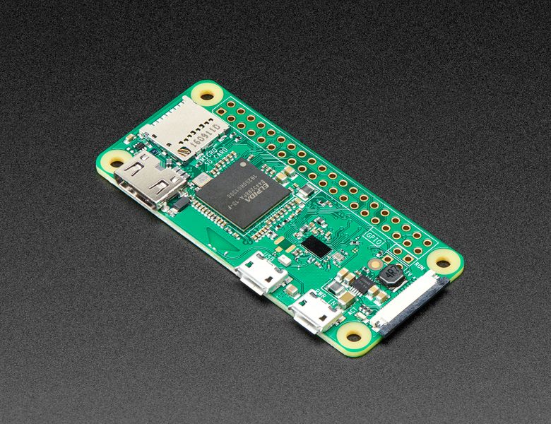
NOTE: This build is alpha quality and is for experimental use. It is missing features and has known issues.Raspberry Pi Zero W Is the first small size (Wifi enabled) Raspberry Pi’s single-board computers. This is the predecessor of Raspberry Pi Zero 2 W with the same form factor.The board incorpo...
lean kiln
Yeah that!
Hopefully another user with Kali expertise may help. Also search the forums / internet for blinka Kali pi
wet mantle
but that is an entire image
and i want to use kali image or raspbian... i just want monitor mode and bonnet to work
wet mantle
no no, give me a sec
wireless adapters are usually used to connect to wifi and receive and send packets, most of the time, that type of function is called managed mode
there is also monitor mode for wireless adapters, mode in which you can capture packets and inject packets
lean kiln
oh wifi monitor or promiscious mode
lean kiln
thought that was more of an adapter setting (along with hardware compatibility)
i.e. should work in raspbian / pi OS
wet mantle
all the examples i saw were using someting called nexmon
which is an custom firmware patch that "enables" monitor mode for adapters without one
and i have trouble getting nexomon to work in raspberry pi os
lean kiln
Oh I see, curious how that works or at least is compatible with different hardware.
I'll be honest, not looked at wifi monitoring in years, since the days of aircrack-ng etc, and mostly I was wireshark or other software. I do remember the adapter monitor mode support being a pain / prerequisite unless you wanted to get your hands dirty compiling
wet mantle
lean kiln
Oh I see, curious how that works or at least is compatible with different hardwa...
haha, aircrack and wireshark are exactly my goals, but didn't expect it to get this hard to get it working on rpi 0
lean kiln
I did get one non-monitor mode adapter working, but it was soo much more sensible to buy a compatible adapter for $15 and save your time / effort
wet mantle
i currently leaning towards that solution, because i don't think i have the expertise to get that to work
i'm trying to make a portable (flipper-like) machine on rpi 0, so my plan was to keep it as small as possible, but will probably end up buying a monitor mode enabled adapter
lean kiln
I distinctly remember failing to get a few non-promiscuous adapters working despite claims to the contrary of some patched drivers.
You'll probably thank yourself for taking the easier path. Also a second tiny usb wifi adapter could be useful in future projects (just dont forget your OTG cable).
wet mantle
aloa?
it's like a rubber ducky on steroids
do you perhaps know would usb hub work on rpi zero?
lean kiln
not sure, a few I've used haven't but most have. Can't remember what it affected, but some things don't like hubs (or at least want them powered)
wet mantle
thank you very much for your time, you saved me quite a few hours
 torn trench
Does anyone know of a good way to maintain mostly similar debug/production images with buildroot? Like if I want to say, add GDB and debug versions of my pacakges to one image? I don't see any way to "include" a defconfig in another defconfig, so it looks like maybe I just have to maintain them in lockstep?
zenith crystal
what you could do is have the main Makefile "create" a makefile from a template with whatever config changes are needed for the debug/prod targets and then have it invoke that makefile
 crystal jewel
g'day - I have a v4l2rtpserver setup on bullseye that has been using an old web-cam and it worked well; today I got a Camera Module 2, and after modprobing the bcm2835-v4l2 driver, rebooting and restarting the v4l2rtpserver it's working - but the image is black and white now!
not sure what the issue here is... can't find anyone else reporting it
might update to bookworm and see if that helps
 hasty tundra
Hello.
I'm using the WiringPi Library for cascading 4 MCP23017 (I2C)
I've dona all basic test and the chip are working and I2C address are right assigned.
My problem is that I am not able (I am not very expert),
to assign an ID to each of them.
For using just one MCP23017, I should use the syntax included in the code below (which works fine),
but if I have to use more than one of these chips, I am not able to assign an ID and associate the subsequent addresses to each one (0x21, 0x22, 0x23)
Kindly, can someone add me the correct string?
import wiringpi
from time import sleep

pin_base = 65      # lowest available starting number is 65
i2c_addr = 0x20     # A0, A1, A2 pins all wired to GND

wiringpi.wiringPiSetup()                    # initialise wiringpi
wiringpi.mcp23017Setup(pin_base,i2c_addr)   # set up the pins and i2c address

wiringpi.pinMode(65, 1)         # sets GPA0 to output
wiringpi.digitalWrite(65, 0)    # sets GPA0 to OFF
...
Hi! Does anyone knows why sgp30 is not being detected by i2c tools?
 steady rose
could be soldering. GND pin looks cold soldered. SDA and SCL are a bit thin.

is that a pi that the SGP30 is connected to?
oh, wait, probably is, didn't see what channel this was
what pins are being used on the pi?
proven fern
1 to vin ,3 to sda,5 to scl and 9 to gnd,i checked with a voltimeter and soldered well
additional to that i tested with an sh1107 display and the display works with the same pins and i2c tools detect the display
steady rose
@proven fern please post this in the forums:
https://forums.adafruit.com/
and ping me with a link to the post. will follow up there.
proven fern
steady rose
<@173073825972486144> please post this in the forums:
<https://forums.adafruit.c...
What forum is the most appropiate for this? maybe Adafruit CircuitPython?
steady rose
proven fern
What forum is the most appropiate for this? maybe `Adafruit CircuitPython`?
yep. that'll work. this one could kind of go various places, so no obvious best.
mystic light
does anyone have any experience using the linux CLI to read the battery status of a connected bluetooth device?
modern matrix
mystic light
does anyone have any experience using the linux CLI to read the battery status o...
I haven't done it myself, but you might find a battery attribute in bluetoothctl list-attributes (may require sudo), or out in /sys/class/power_supply:
mystic light
yeah, I tried that and I don't get any result from list-attribut4es
mystic light
looks like I can parse a bunch of info from pacmd or pactl and extract a rough battery percentage
mystic light
anyone have experience with pigpio?
faint sparrow
Hey guys, i have a problem, the black usb cable is for the powering and it’s working, the hdmi is working too but the white usb cable for my mouse, is on when I turn on the raspberry li but I can’t use it like when I move it, it doesn’t move on the screen. Am I doing something wrong?
 zenith crystal
open a terminal (or ssh to one) and type lsusb and see if it's showing up
 simple storm
I was told to ask in this channel for help with Linux in pi’s. Currently I’m trying to set up a pi4 model B with a bonnet attached to a 64 by 32 led matrix. I’ve been prying at this for weeks. I’m trying to display an image on the pi like this one. I’ve followed tutorials and walkthroughs online but have been running into errors and issues. Does anyone have experience with led matrixes and pi’s? If so, any help would be much appreciated

 mystic light
just show some of the errors you're getting and people will jump in if they can help
steady rose
also, is it working as expected per the guide?
https://learn.adafruit.com/adafruit-rgb-matrix-bonnet-for-raspberry-pi/overview
and you're just looking for how to show an image?
steady rose
faint sparrow
Hey guys, i have a problem, the black usb cable is for the powering and it’s wor...
what os version are you using? is there also a keyboard attached? are you able to ssh into the pi?
faint sparrow
steady rose
what os version are you using? is there also a keyboard attached? are you able t...
I just powered up the pi for the first time and I have to click the “next button” to open up. I’m using 32 bits OS
faint sparrow
zenith crystal
open a terminal (or ssh to one) and type `lsusb` and see if it's showing up
The pi is not configured yet, this is the first powering for it
steady rose
desktop version of pi os? or lite?
faint sparrow
I downloaded raspberry bookworm iso, I think is desktop yeah
steady rose
are you able to ssh into the pi?
faint sparrow
steady rose
are you able to ssh into the pi?
I can’t yet, cause that was the first powering for the pi
I still not able to log in the desktop cause I have to click a button but I can’t click it cause the mouse is not working on it
steady rose
troubleshooting will be difficult without getting into the pi somehow. try setting up ssh so you can access it that way.
faint sparrow
Do you mean setting it up in my windows on the SD card before plug it in?
steady rose
yes. it can also be enabled when originally creating the SD card image. its an option in rpi-imager.
faint sparrow
The only pre-configuration I did is that I created an empty file named ssh on the root folder of the image
steady rose
i'm not sure that approach works anymore with latest OS's
faint sparrow
Oh really, I only followed a guide on a site cause I never worked with a Pi before
steady rose
it might be an old guide
this one shows the file stuff:
https://learn.adafruit.com/raspberry-pi-zero-creation/text-file-editing
but also mentions it not working on latest releases
instead, use rpi-imager:
https://learn.adafruit.com/raspberry-pi-zero-creation/using-rpi-imager
(those screenshots are most likely out of date)
faint sparrow
I actually didn’t download the image that way
Cause I tried first but it kept showing errors
faint sparrow
So I downloaded the image iso as a zip and then downloaded another app called “balenaEtcher”
And downloaded it that way
steady rose
rpi-imager is the new etcher
you can use pre-downloaded images with rpi-imager
that's what i do
the ability to download within the imager is just a convenience feature
it's generally the last option in the scroll down for the operating system choices
 faint sparrow
Can you suggest me an image to download
There’s a lot of options and I don’t know which one is good for me
steady rose
what are your plans for the pi?
faint sparrow
I asked an AI before and it says better be 32 bits
faint sparrow
steady rose
what are your plans for the pi?
You mean what I will use it for?
steady rose
yep
faint sparrow
Oh it’s gonna connect to an active device by sending some protocols and get the address MAC and the name of that device then send it to my computer by using PuTTY and store the informations in SQL. There’s also an arduino uno connected to the Pi by I2C communication cause this is sort of a robotic project so, there’s infra rouge sensors in the arduino
I Hope you understand what I said
steady rose
sounds like you don't really need the desktop version then?
faint sparrow
I need to code this in the raspberry I desktop?
The data base and the arduino configuration will be inside the raspberry Pi
I really don’t know. This is my first time for a raspberry. If you have any idea, I’ll be happy to know
steady rose
are you wanting to run the Arduino IDE on the Pi? or are you programming the UNO separately?
faint sparrow
No, I will program them separately
Arduino IDE on windows
And python script in a raspberry to send and receive data from the arduino
steady rose
are you OK with doing things via a command line only?
faint sparrow
steady rose
are you OK with doing things via a command line only?
I think that’s high level, I’m just a sophomore IT student
I don’t know how
steady rose
ok, probably just go ahead and grab the desktop version:
https://www.raspberrypi.com/software/operating-systems/
and then use rpi-imager to create the SD card image
and have rpi-image do some of the initial configuration, like network, enabling SSH, etc.
faint sparrow
steady rose
and have rpi-image do some of the initial configuration, like network, enabling ...
To do that, I can use the guide you sent me before right?
faint sparrow
Emm there’s another problem I guess
steady rose
they seem to change it with each rpi-imager release
faint sparrow
I read in that guide that the pre-configuration doesn’t work in the latest version “bookworm”
steady rose
that's for doing things via text files only
that's like the "old" way to configure things
faint sparrow
Oh so i will configure it inside the imager
steady rose
the guide is showing both an "old" way (text files) and a "new" way (rpi-imager)
faint sparrow
steady rose
the guide is showing both an "old" way (text files) and a "new" way (rpi-imager)
I got you
steady rose
yep. ignore the "Text File Editing" stuff.
faint sparrow
So I will choose the costume option on the OS inside the imager right?
And choose the iso I downloaded
And then follow the guide
steady rose
yep. and then you can select the 2024-03-15-raspios-bookworm-armhf.img.xz file downloaded above
use the guide as a reference, but the menu options might be different
different menu layout/location
faint sparrow
Yes I will pay attention to that and read everything
So after that, I can access to the desktop without clicking any button?
steady rose
the main thing is to get networking and ssh working
so you have that as an option for accessing the pi
if the attached mouse/keyboard are not working for some reason, then you're kind of stuck
and ssh'ing in will allow trying to figure out why
mystic light
you can also use VSCode over ssh, though it doesn't work great on the RPi Zero,
steady rose
the pi zero is one of the trickier Pi's to get working, since it has such minimal ports
faint sparrow
Yes I have the pi zero 2 and the ports are limited. Now I have only one USB port available to change between the mouse and keyboard after
mystic light
if you can, getting a usb2go hub with an integrated ethernet could help a lot
if you plan on doing desktop development I would strongly recommend it, if you can develop over ssh, it's less important
faint sparrow
mystic light
if you can, getting a usb2go hub with an integrated ethernet could help a lot
You mean the one that has multiple USB ports?
mystic light

One can never have enough socks, or USB ports. Add some more USB and Ethernet capability to your Raspberry Pi Zero or, really, any kind of tablet or computer with an OTG connector ...
 barren mantle
I hope I am asking this question in the right place ... sorry in advance if I am not.
I am trying to build the "Raspberry Pi Wearable Time Lapse Camera" (https://learn.adafruit.com/raspberry-pi-wearable-time-lapse-camera/overview).
As part of that, there is a step to install wiringpi
sudo apt-get install -y wiringpi
When this command is run the "no installation candidate" error is thrown.
$ sudo apt-get install -y wiringpi
Reading package lists... Done
Building dependency tree... Done
Reading state information... Done
Package wiringpi:armhf is not available, but is referred to by another package.
This may mean that the package is missing, has been obsoleted, or
is only available from another source
E: Package 'wiringpi:armhf' has no installation candidate
What is the solution? How can I build the "Wearable Time Lapse Camera?" Especially since I just purchased all the hardware 🙂 ?
ALSO, is there anyway to take video rather than just a picture every two seconds?
mystic light
what board are you using, what OS do you have installed?
barren mantle
https://learn.adafruit.com/raspberry-pi-wearable-time-lapse-camera/overview
Rsapberry Pi Zero 2W running Bookworm.
 steady rose
@barren mantle that may be out of date info. looks like it's only mentioned in a code comment. have you gone as far as getting Blinka installed?
steady rose
it was a typo and has been removed:
https://github.com/adafruit/Adafruit_Learning_System_Guides/pull/2800
in general, it should nominally work once Blinka is installed
note the code has been moved from a shell script (.sh) to a python file (.py)
don't use the shell script
wiringpi is not used
barren mantle
Thanks. It didn't say that two days ago!
Two days ago - and the prior week when I started this, Blinka wasn't mentioned.
steady rose
yep. looks like those updates are very new. so just coincidence on when it was updated. thats happening right now to various pi guides. and there may still be some that are showing outdated info. this is a good place to get help when you run into one of those.
faint sparrow
Hey guys, I have a problem on my raspberry li zero 2W. Even though I added my wifi in the imager while downloading. It still can’t activate when I turn the desktop on
What’s the problem going to be?
zenith crystal
this implies that you have a desktop, so open a terminal and run sudo cat /etc/wpa_supplicant/wpa_supplicant.conf -- it should look like ```ctrl_interface=DIR=/var/run/wpa_supplicant GROUP=netdev
update_config=1
network={
ssid="Your Wifi"
psk=your sshkeyencrypted
}```
make sure you're using the appropriate wifi channel (b/g/n)
 woeful grail
Hello, does anyone here have any experience with using the luma.oled library with an SSD1327 OLED? I'm having trouble displaying all 16 shades of grey, I seem to only be getting a max of 5 no matter how I try to specify which shade to render
 idle widget
Hi there! I was wondering 2 things about the now discontinued IOT printer kit V2:
Has anyone "repurposed" the kit for things other than twitter/x?
Can I use the NOOBS SD card that came with the kit with a Pi zero 2 w?
Any assistance with this would be amazing
I'm not really skilled in software, but am willing to try and learn
Thank you!
 hollow ocean
I have a shell (Bash) script that is not behaving as expected, and hoping someone can help. Relevent line is:
time ls *.tif | /usr/bin/time --output=stats.txt -a parallel "tesseract {} {.} --oem 1 -c hocr_char_boxes=1 hocr"
what I'm expecting to happen that the call to /usr/bin/time will trigger an output either to the terminal or, worst case, to the log (stats.txt) file for each file that is being processed (either, when it finishes or when it starts). Right now, I get one output to the terminal and one to the log only when the entire run is finished
I could switch to something like for f in *.tif; do printf (time, f); tesseract" (slightly pseudocoded for brevity) but, assuming that I understand how parallel and pi clusters work, that wouldn't allow me to move the script to a pi cluster and make full use of each board.
Am I missing something for getting parallel to echo something to at least the log, if not (ideally) the terminal as it works on each file?
 vagrant lance
i think you want the time invocation in the parallel one: parallel “time … tesseract …". you might have trouble with order of writing and stuff though. that initial time invocation is only measuring the time to list files though
hollow ocean
And the second one is measuring the time to process all files? At least that is what the output looks like
I'll try (tomorrow) putting the time in the parallel invocation and see what happens (it's bedtime here, so, too late to try it now)
vagrant lance
hollow ocean
And the second one is measuring the time to process all files? At least that is ...
yep! it’s the time for the whole parallel run to finish
hollow ocean
vagrant lance
yep! it’s the time for the whole parallel run to finish
That makes sense. Would be even better if I could get the file name out to terminal and filename and time to the log - that particular call takes a long time to run, and unless I'm watching the directory, can seem like it hung up or crashed X
vagrant lance
indeed; then you’d want to probably throw the tesseract invocation into its own little script which first outputs the filename etc. but probably separate log files otherwise they’ll all be interleaved
hollow ocean
Problem with the tesseract call in it's own script, it wouldn't use parallel the same way, which would make using a cluster be worthless, wouldn't it?
I'm probably missing something about how parallel and clusters work, been a long time since I looked at clusters, at the time I didn't have a need
vagrant lance
assuming it's GNU parallel (parallel --help can indicate), it and tesseract know nothing about each other, so calling tesseract directly as its command argument, or from within a shell script, doesn't make a difference
parallel just runs copies of the requested command line at the same time, one for each input line. (and you can cap it to run only n at once with -j n etc.) i'm not sure what "cluster" implies for you, nor do i know anything about tesseract, but you'll probably need to do some extra legwork to distribute it across multiple machines?
hollow ocean
vagrant lance
parallel just runs copies of the requested command line at the same time, one fo...
Pi cluster is using, say 4 (can link a whole lot more) raspberry pi, linked together. The first acts as a controller, the other 3 end up working like the individual cores of a triple core cpu, each one using the resources of their individual board to complete the task they are assigned
(The link describes an 8 pi cluster, I'll probably only do 4)
vagrant lance
sure, i see. they’re logically separate; parallel won’t do anything across them by itself.
hollow ocean
My big problem with pulling the tesseract call into its own function is tesseract doesn't appear to accept globbing, or allow iterating over a directory, that is the primary purpose parallel is serving at this moment (basic tesseract call is tesseract imagename.ext imagename hocr anything else is options and switches - attempting to use basename to pull just the file name without extension for the output or a globbing type call for the input does not give the expected result of a ocr file with the same name as the input file but the extension of the ocr file)
vagrant lance
right, yeah; you could also just do that with a shell loop if you didn’t want to parallelise it on the local node
hollow ocean
vagrant lance
sure, i see. they’re logically separate; `parallel` won’t do anything across the...
Parallel says (haven't found the options) that it can be used to distribute workload across multiple computers - like way back when the seti network was getting people to process their images/files on their home computers)
hollow ocean
vagrant lance
right, yeah; you could also just do that with a shell loop if you didn’t want to...
Yeah, a shell loop will be my backup plan
vagrant lance
hollow ocean
Parallel says (haven't found the options) that it can be used to distribute work...
true — i see https://ulhpc-tutorials.readthedocs.io/en/latest/sequential/manytasks-manynodes/ and https://unix.stackexchange.com/questions/341264/running-gnu-parallel-on-2-or-more-nodes-with-slurm-scheduler for this.

Unix & Linux Stack Exchange
I am trying to distribute independent runs of a process using GNU Parallel on a HPC that uses Slurm workload manager. Briefly, here is the data analysis set up:
Script#1: myCommands
./myscript -...
hollow ocean
(I'm looking into how the cluster distributes work now, I might be stuck on parallel for no reason)
vagrant lance
yeah, there's a bunch of different ways you could orchestrate it. like that tutorial you mentioned uses parallel-ssh, which appears to be a little toolkit to do similar kinds of things.
it wouldn't surprise me if parallel could also record all those timings itself somehow, it seems to be a bit of a swiss army knife too
otherwise you could do parallel "/usr/bin/time tesseract {} {.} …", if it can collect the stdout/stderrs for you
hard to suggest more concrete things, but i think you do have everything you need to do it, just gotta glue it together nicely!
hollow ocean
vagrant lance
otherwise you could do `parallel "/usr/bin/time tesseract {} {.} …"`, if it can ...
It can capture the stderr/stdout, the big problem is, there is no stdout/stderr if the file is successfully processed. If I feed an image that has no text to recognize, for instance, I get, to terminal only, empty file. Nothing to do. If there is text on the image, it runs and exits silently, so, I have to add stdout for those
vagrant lance
oh sure; I meant /usr/bin/time will add its own.
hollow ocean
Ah, gotcha
faint sparrow
zenith crystal
this implies that you have a desktop, so open a terminal and run `sudo cat /etc/...
What is (b/g/n)?
hollow ocean
faint sparrow
What is (b/g/n)?
The 802.11 network type. Either b, g or n
faint sparrow
hollow ocean
The 802.11 network type. Either b, g or n
Can you give me an example? I really don’t know what is that
hollow ocean
faint sparrow
Can you give me an example? I really don’t know what is that
Give me a few to try and find what you are trying to do and what hardware you have
faint sparrow
hollow ocean
Give me a few to try and find what you are trying to do and what hardware you ha...
You want me to give you what components I will use with the Pi?
hollow ocean
Looks like you've got a pi 0, are you using an internal wifi chip, or an adapter? If an adapter, which one? Also, what router do you have?
faint sparrow
I have a pi zero 2 W, it has already wifi and Bluetooth integrated
It supports wireless LAN
hollow ocean
Ok
faint sparrow
And the operating system im using is bookworm 32bit with desktop
hollow ocean
So, your on board wifi supports 802.11b or 802.11g or 802.11n. Let's skip the confusion on that for right now. Is your wpa-supplicant file configured properly
zenith crystal
what is the output of the command i asked you to run?
faint sparrow
zenith crystal
what is the output of the command i asked you to run?
I didn’t run it yet
hollow ocean
Need to run it, or on board chip supports the b/g/n thing, so don't worry about it
barren mantle
steady rose
yep. looks like those updates are very new. so just coincidence on when it was u...
Unfortunately, the update doesn't work. The push-button switch and the sequin LED don't work. Also, the case doesn't work with a Raspberry Pi Zero 2 W. the Wifi chip and the PowerBoost clash. I did supbmit "feedback and correction."
steady rose
barren mantle
Unfortunately, the update doesn't work. The push-button switch and the sequin LE...
have you tried some simple digital in/out test scripts to test the basic functionality of the button and the LED?
mystic light
Ok, really weird issue:
rp5: rasp5 running NanoMQ MQTT broker
wp1: W5500-EVB-PICO (rp2040) running minimqtt, listening for commands
wp2: W5500-EVB-PICO running minimqtt sending out sensor data 1/sec on different topic channel
pc: running python paho-mqtt sending commands 1/sec to wp1, also running Mqtt client to monitor rp5
rp5, wp1, wp2 connected through ethernet switch on a private subnet
rp5, pc connected to wireless network on different subnet
when wp2 is disconnected, everything seems to run fine, rp5 broker gets the commands from pc, sends them on to wp1, wp1 parses the command
when wp2 is connected, broker still sees cmds from pc, gets sensor data from wp2, but wp1 no longer gets the commands from the subscribed topic. If I disconnect wp2, wp1 will 'recover' and start receiving commands again.
Problem still occurs after switching to rp5 Mosquitto MQTT boker. Problem sill occurs when wp2 is talking to NanoMQ broker, and wp1/pc is talking to Mosquitto broker on different rp5 ports! rp5 is showing almost no CPU/memory utilization because load is so low.
I'm at a loss. I'll try to spin up a broker on a PC, but is there some weird connection limitation on the rp5?
zenith crystal
try a combo with the pi5 out of the equation -- run the broker on the PC; you might also try running the broker with debug logging enabled
also, what are you using for client identifiers and what QoS are you using?
mystic light
sorry, should have updated here. The problem was default MAC addresses for the circuitpython W5500 library. As soon as I added another EVB-PICO, I got MAC collisions galore. When I initialized the w5500 with individual different MACs, everything runs smooth like butter
faint sparrow
Hey guys, I have a problem, why the pi doesn’t power on my screen? It keeps saying (no image found) and then power on the colourful screen and then again ( no image found)
 zenith crystal
it's saying it can't find anything to boot -- the SD card isn't inserted, is damanged, or isn't properly formatted; the alternative is your pi hardware is bad 😿
faint sparrow
The last week was working normally, and I entered the desktop. But someone told me that the iso I used is not good so i formatted the SD card and installed another one. But her we go, nothing is showing, can the problem be from the HDMI cable or the display?
zenith crystal
i'm confused, if it was working why would someone tell you it was bad? (i hope to bleep it wasn't me? 😊 )
also, if you had it working, i'd go back to that version (i guess -- i don't know what your intent here is)
faint sparrow
No no it wasn’t you but it was in this server hahaha
I installed it last time with balenaEtcher, not with the imager. That’s why it worked well
What do you advise me with?
steady rose
what OS images have you downloaded so far?
downloaded = you have a local copy of the OS image file
zenith crystal
the "how" between the two isn't that much different, but ☝️
steady rose
filenames are probably most useful and specific. for example, have you downloaded a copy of 2024-03-15-raspios-bookworm-armhf.img.xz ?
faint sparrow
I downloaded this one
 steady rose
do you know where the file 2024-03-15-raspios-bookworm-armhf.img.xz is located on your PC?
faint sparrow
steady rose
do you know where the file `2024-03-15-raspios-bookworm-armhf.img.xz` is located...
It’s On my downloads
steady rose
do you have the rpi-imager software installed?
https://www.raspberrypi.com/software/
faint sparrow
I unzipped it there
faint sparrow
steady rose
do you have the rpi-imager software installed?
<https://www.raspberrypi.com/soft...
Yes I do
steady rose
no need to unzip
faint sparrow
And I followed all the instructions
steady rose
ok, run rpi-imager and use that to burn the 2024-03-15-raspios-bookworm-armhf.img.xz image to the SD card
but also got through the configuration setup
configure network, enable SSH, etc.
faint sparrow
Yes yes I did all that
steady rose
that is a step that is done before writing the image
faint sparrow
I configured the network, enabled SSH and put a username and a password too
steady rose
did you choose the file 2024-03-15-raspios-bookworm-armhf.img.xz ? or something else that showed up after unzipping?
faint sparrow
I chose that one, I made sure that there was only one zipped file on my downloads
steady rose
and when you put the SD card in the pi, it is acting like it can not find an OS image?
faint sparrow
Oh one thing, why when the installation finishes, the SD split into two?
faint sparrow
steady rose
and when you put the SD card in the pi, it is acting like it can not find an OS ...
Yes, it starts with a colored screen and then it says ( no image found)
faint sparrow
steady rose
oh, like folders that show up?
Wait I’ll show you
steady rose
bootfs and rootfs folders are showing up?
 steady rose
that's just the resulting partition scheme on the SD card after imaging
faint sparrow
So it doesn’t mean, something is wrong right?
steady rose
no. that is expected.
and indicates the imaging worked
the bootfs partition is FAT, so will show up on pretty much anything
the other partition is not, so probably won't show up on windows
steady rose
but in general, you can ignore those. at that point, just eject the SD card, put in Pi, and boot
faint sparrow
Or the hdmi port of the display
steady rose
hdmi in general can be tricky
faint sparrow
Since the display is pretty much old
Is there any possible way to display it on a laptop?
steady rose
only via SSH, VNC, a USB serial cable, etc.
might be worth trying to set hdmi_safe=1 in cconfig.txt
faint sparrow
In the bootfs folder?
steady rose
do you remember what was working previously?
faint sparrow
i did it on balena betcher
steady rose
see if you can repeat your previous success
balena etcher should produce a bootable SD image. however, it won't be able to do any of the configuration stuff.
faint sparrow
yes i have to configure it manually, but i hope i work again. i'll try
steady rose
just curious - why have you chosen a pi zero to work with?
faint sparrow
should i also try another version of iso? maybe an old one
steady rose
use whatever iso worked before
faint sparrow
steady rose
just curious - why have you chosen a pi zero to work with?
because it's the only one i can afford for now (graduation project, limited budget). those components are so expensive in my country. i bought this one (without any pins ports or hdmi usb) with 36$
steady rose
ok. no worries. it's a perfectly fine pi. just a little harder to work with.
having one of these (or something similar) can really help when working with a pi zero:
https://www.adafruit.com/product/954
faint sparrow
what does that one do please?
steady rose
very simple - it's a USB-to-serial adapter
it's general purpose, not Pi specific
but it would allow connecting to the serial console output on the Pi's header pins
there are lots of "USB-to-serial" adapters out there. it doesn't need to be that specific one.
steady rose
there's also this in case you're concerned about the pi itself:
https://learn.adafruit.com/raspberry-pi-zero-creation/is-my-pi-zero-dead
faint sparrow
the green led is on, and it blinks when i power it on only
faint sparrow
Do I have a way to interact with a linux sbc without plugging it in a monitor first? I thought ssh, but it needs first to be enabled, so no
mystic light
Depends how the os is installed, for example you can set up network and ssh on a raspberry pi during the os install
steady rose
ssh (yes, you do need to enable it, but is easy) or console cable (see links/discussion above)
faint sparrow
Ah I am not using a raspberry, but a khadas vim1; pretty sure that their flash tool doesn't allow the enable ssh directly
https://docs.khadas.com/products/sbc/vim1/install-os/install-os-into-emmc-via-usb-tool
Other raspberry "bootlegs" seem to be the same or am I wrong?
modern matrix
it really depends on the image. I think Raspberry Pi OS disables SSH by default these days, but you can place an empty ssh or ssh.txt file on the boot partition to enable it
zenith crystal
no, the imager allows you to set wifi and SSh credentials while burning the disk -- basically it creates the default user for you
mystic light
kind of linux related: I keep running into read-only mounting for my W5500-EVB-PICO when attaching it to my headless linux system, any thoughts?
humble marsh
mystic light
kind of linux related: I keep running into read-only mounting for my W5500-EVB-P...
that usually happens becuase the filesystem got corrupted in some way. Are you do a hard reset or disconnecting when a write is in process?
mystic light
I don't think so, it works fine plugged in to my windows computer
humble marsh
mystic light
I don't think so, it works fine plugged in to my windows computer
you could try copying everything off and then doing, in the REPL:
import storage
storage.erase_filesystem()
eject it cleanly
Then try it on the Linux system. That will give us some info about whether it's the system or not. Then you can copy the files back.
It's possible you have some udev rules on Linux that are forcing it to mount readonly. I have not seen that before, though. I use these boards all the time on Linux (Ubuntu) without seeing that problem.
mystic light
on headless systems?
also, I'm doing a proxmox USB passthrough to a VM, so maybe that's interfering somehow
humble marsh
mystic light
also, I'm doing a proxmox USB passthrough to a VM, so maybe that's interfering s...
it's a VM with virtualized USB?, hmm, things could go wrong with USB sure, or maybe it's a security thing (no leaking data to a USB drive)
mystic light
but you've used headless linux systems with usb/circuitpython before? I remember there's some issue with automounting if you're not running a linux GUI desktop
this is what I get from dmesg:
[    2.604534] scsi 3:0:0:0: Direct-Access     WIZnet   W5500-EVB-Pico   1.0  PQ: 0 ANSI: 2
[    2.604649] sd 3:0:0:0: Attached scsi generic sg2 type 0
[    2.606474] sd 3:0:0:0: [sdb] 2049 512-byte logical blocks: (1.05 MB/1.00 MiB)
[    2.607301] sd 3:0:0:0: [sdb] Write Protect is on
[    2.607302] sd 3:0:0:0: [sdb] Mode Sense: 03 00 80 00
[    2.608894] sd 3:0:0:0: [sdb] No Caching mode page found
[    2.608895] sd 3:0:0:0: [sdb] Assuming drive cache: write through
in any case, the storage.erase seemed to work
humble marsh
mystic light
in any case, the storage.erase seemed to work
that is interesting, because that would indicate the drive was corrupted enough to be presented as read-only or was detected to be corrupted on mount
yes, sometimes automount is not enabled, but you should be able to mount r/w manually
junior edge
Hey there, I'm currently having an issue using luma.oled with spi. I believe I have the device and ID setup properly, yet I keep getting this error :/
 steady rose
what does ls /dev/spi* show?
junior edge
 junior edge
Sorry for the late response, I have been busy with school all day
ok so I did some misc other things in the misc configs file and got the code not crashing when I set the devices to = 0. How do I ensure that the devices are correct?

Also is there a chance I got the cabling messed up?
junior edge
Ok I think I wired it wrong, redid it, but still nothing appears. Is there anything else I need to ensure I did to get IPS working?
Im running a slightly modified version of what the docs tell me to run
 junior edge
VCC:1
GND:6
SCK:26
SDA:24
RES:22
DC:18
CS:11
junior edge
so for some reason now I keep getting an error where luma is just not found??? I chose to wipe my Pi (was already running another project), did a fresh install with a minimal pi setup, installed the library, and now it gives me an error saying luma isnt found
I try to manually install the luma module and I keep getting the error. Issue arises from the first import in the code I sent
this is super infuriating
ornate bluff
Would a SATA power port's 5V rail provide enough power to run a raspberry pi
broken shuttle
ornate bluff
Would a SATA power port's 5V rail provide enough power to run a raspberry pi
Uhh... maybe? Not sure how close to 5V those rails typically are.
ornate bluff
Hmm it seems like the spec provides for 2A of power, and both the USB spec and the SATA spec specify +- 5% so I think it would work, but I'm not sure if there's something else that would influence that
broken shuttle
2A is not enough.
A lot of PSUs can easily power 3 or 4 drives, but not many drives will draw that much from the 5V rail.
ornate bluff
How much is enough for a pi? I thought the stock USB adapter was a 2 amp one
It's a pi 4 if that changes anything
wraith grove
At this point I might suggest "can use up to".
broken shuttle
RPi 4 and 5 are both known to have frequent brown-out issues.
And are very sensitive to anything below 5V.
 strong barn
pi 4 is 15w, 5v@3A : https://datasheets.raspberrypi.com/rpi4/raspberry-pi-4-datasheet.pdf
"The Pi4B requires a good quality USB-C power supply capable of delivering 5V at 3A. If attached downstream USB devices consume less than 500mA, a 5V, 2.5A supply may be used."
If you're trying to power it off of an existing PC's power supply, maybe try something like this? https://www.amazon.com/2-Pack-Female-Converter-Adapter-Module/dp/B0C2KJJNM2/

2-Pack 12V 24V DC to 5V 3A USB Female DC Converter Adapter Buck Module
I'm not vouching for that one specifically, just an idea of what you might look for
cunning quarry
Hey guys, would anyone know how to setup a GT-U7 for a raspberry pi raspbien bookworm?
It's wired already, but I am not too sure on the libraries and such to use.
I have tried this already --- sudo apt install gpsd gpsd-clients python3-gps -y, is this correct?
Any pointers to the correct path to get this GT-U7 gps would be appreciated, thank you!
zenith crystal
that is no longer the correct way to install python packages -- the recommended way is to use a virtual environment -- see https://learn.adafruit.com/circuitpython-on-raspberrypi-linux
Adafruit Learning System
Make hardware and interface with sensors super easy using CircuitPython libraries
cunning quarry
Ok cool so I assume "pip3 install adafruit-circuitpython-gps" would be acceptable for the GT-U7 I'll try this out.
mystic light
they recommend pip install using a virtual environment, but there's nothing wrong with sudo apt install python3-<python package>, and lots of 3rd party applications depend on that functionality. It's just that many python packages aren't in the apt repository
 tidal magnet
@mossy barn There is a DC / Stepper Motor Hat made for Raspberry Pi and it has a learn guide that covers it's usage: https://learn.adafruit.com/adafruit-dc-and-stepper-motor-hat-for-raspberry-pi/using-dc-motors It might be a bit different if you're not using the exact same driver hat, but the software side should be fairly close I would imagine even if using a bit different hardware.
 mossy barn
You cant use a dc motor directly on a pico right @tidal magnet
I think i have a l298n module somewhere lol
tidal magnet
mossy barn
You cant use a dc motor directly on a pico right <@382939733107408897>
I don't think so, but I'm not sure. Also if it is a Raspberry Pi Pico that you have as opposed to a full Raspberry Pi Linux SBC the #help-with-circuitpython is actually the right place for the discussion. I think in your original question you didn't mention pico which is why it was suggested to move over to here.
@mossy barn there is this guide: https://learn.adafruit.com/use-dc-stepper-servo-motor-solenoid-rp2040-pico that includes information about DC motors on the rpi pico.
steady rose
^^ good info there. yep, not directly. at a minimum, need an h-bridge.
or i guess a transistor for single direction on/off style control
humble marsh
@rancid knot Do you see this?
https://learn.adafruit.com/adafruit-voice-bonnet/audio-setup

 rancid knot
Hi! Hopefully someone can assist me. I bought the Voice Bonnet and have been following Kattni's guide to help me get this to work on a RPi Zero 2 W. I've followed the directions but the Zero just locks up trying to build the kernel. I've tried several times. I'm using the latest build of Bookworm. Do you know of any way I can get this to work? I feel like I've wasted my money.
humble marsh
not sure if that is true of bookworm in general
but why did you mention the kernel?
I don't see anything about kernel changes in the guide
rancid knot
Yes. I hope it is not and is only specific the the RPi %
The kernel build for me came with the command line of "sudo ./install.sh" but I'm not sure why.
I was a little worried when I saw that but thought it was part of the install.
rancid knot
This applies in the first one. 🤷 It's odd because the kernel that comes with bookworm was much newer than what was being built so that's why I'm here.
humble marsh
There is a lot of discussion of the Voice Bonnet in our forums: https://forums.adafruit.com/search.php?keywords=voice+bonnet&sort=BestMatch. I am not familiar with it at all, sorry. It would be worth reviewing those threads if you haven't already. And perhaps opening your own thread if there isn't an applicable one.
rancid knot
I did look there but couldn't find an answer. I will open a thread but hoped that I could get help here. JP always says we can "Ask an Engineer" in Discord. I don't see that here . . . . . yet.
humble marsh
For now, I think a thread there is your best bet. The warnings I showed above indicate that there is some attention being paid to this, though maybe no fix yet. The official support people are in the forums. DIscord is all community and casual support by Adafruit engineers when we have time.
rancid knot
I will do that then. Thank you for your time.
strong barn
@rancid knot I have the equipment and was running it just fine last year, but that was before bookworm. Maybe try going back a version for the time being?
 fickle rose
So looking at a zero 2 w how would i use that u.fl footprint, just solder it on and bridge those pads? Or would something need to be done to the built in antenna
 humble marsh
fickle rose
So looking at a zero 2 w how would i use that u.fl footprint, just solder it on ...
strong barn
humble marsh
fickle rose
So looking at a zero 2 w how would i use that u.fl footprint, just solder it on ...
strong barn
I got the parts in to try and do the same thing! I am just afraid of sneezing off those tiny resistors while setting up
rancid knot
strong barn
<@1241195467224645664> I have the equipment and was running it just fine last ye...
Yes, I started with Bookworm and now am trying Bullseye but I still get the same results. Quite frustrating to spend money on something and can't even use it.
I am hoping that if the Linux OS continues to evolve that @keen ridge and/or @lost wolf would update the Voice Bonnet instructions so this doesn't happen. Lady Ada and Co. has been so excellent in providing the best support for the companies products.
rancid knot
In reference to my message above I was able to get this to work on my Raspberry Pi Zero 2 W. An addition to the documentation would be "When using a 64 bit CPU you can get this to work with the Raspberry Pi OS Lite (64-bit) Bullseye release NOT the Bookworm release." I did get this to work after just a couple of weeks of trial and error.
humble marsh
mossy barn
is there any documents on circuitpython and relays?
how about https://learn.adafruit.com/adafruit-stemma-non-latching-mini-relay search for "relay" in the Learn Guides for other guides as well
mossy barn
humble marsh
how about <https://learn.adafruit.com/adafruit-stemma-non-latching-mini-relay> s...
exactly what I needed
thanks bud
strong barn
For the RPi 5, has anyone come across a less clunky charger? Or ideally, a multi-port USB charger that supports the correct 5v5a profile?
modern matrix
you should be able to get away with 3A if you don't have any USB peripherals or other power draws attached, I think. otherwise, yeah, might need that 5A.
broken shuttle
strong barn
For the RPi 5, has anyone come across a less clunky charger? Or ideally, a multi...
Unfortunately, RPF designed themselves into a corner with this. Supplying 5V at 5A over more than a couple feet is difficult.
 twin helm
and i recall it needs stricter voltage regulation than required by the USB VBUS spec?
broken shuttle
Significantly stricter
twin helm
ugh why not do actual USB-PD and have a switching regulator on board?
broken shuttle
twin helm
ugh why not do actual USB-PD and have a switching regulator on board?
That's a question I've been asking for the last decade, and the reason I don't recommend anything beyond the 3B+.
Even a 12V barrel jack would have been better than what they did.
strong barn
They said something about cost and board space tradeoffs, but I don't remember the details
“Both the PMIC and the power supply support the USB Power Delivery (USB PD) standard. With USB PD there’s a little serial interface running over the power cable. You talk to the power supply, it starts off at five volts, but then you ask it: ‘what voltages do you support?’. And it says: ‘I support all these voltages.’ Usually it’s five, nine, 15, 20 volts if you’ve got a PC one. We could have just used a standard PD supply, get nine volts at three amps, but then you have to do the voltage conversion on the board. That costs you area, it costs you silicon, it costs you efficiency. So, we decided to do something a little bit non-standard, which is what we often do in search of performance, and create a five-volt, five-amp profile for our power supply. That means you don’t need all that conversion, but it can still support the board, and if you’re using the new supply we can support extra USB current downstream compared to Raspberry Pi 4. Or more HAT current.
I know there's a PoE hat out there, I think there are efforts to make other power option hats
but hey, maybe someone at adafruit will see this and decide to produce a hat (or similar hardware) that can add a barrel jack, PoE+ support, and/or other power options
broken shuttle
strong barn
```
“Both the PMIC and the power supply support the USB Power Delivery (USB PD) ...
Yes, and to put it bluntly, their justification is stupid.

(I need to sleep, so I can't pick apart their logic at the moment, but suffice it to say I disagree with the tradeoffs they made.)
modern matrix
When using a standard 5V, 3A (15W) USB-C power adapter with Raspberry Pi 5, by default we must limit downstream USB current to 600mA to ensure that we have sufficient margin to support these workloads. This is lower than the 1.2A limit on Raspberry Pi 4, though generally still sufficient to drive mice, keyboards, and other low‑power peripherals.
(that 600mA is the total budget shared across all USB ports when using a 15W power supply on a Pi 5)
if you needed more than 600mA for your USB devices, you could use a 5V 3A supply for the Pi 5 and a separate power supply for a powered USB hub (one that doesn't backpower the host), and I bet there are multi-port chargers that can provide both power supplies in one device that are easier to source than the rpi 5A one
strong barn
the only problem (and I don't know if it is, because I haven't tested) is that I am planning on using various hats, and I don't know if they'll stay inside the power budget if using an unofficial 5v3a power supply.
If it crashes, I'll find out the hard way 🙂
zenith crystal
the easy way to ensure it works is if the hat has a separate power supply, use it 😏
and don't try to "back power" the pi through the hat
modern matrix
seems like a big ask for a HAT, heh
zenith crystal
i have to be careful about making sure everything is powered off when "doing stuff" because a lot of hats will also power the pi, so like my crickit will leave the pi "on" if i don't turn it off as well (and yeah, it doesn't work that well once you attach any motors or the like 😀 )
 tight ridge
hi @hushed vortex ... read your article at https://adafruit-playground.com/u/MakerMelissa/pages/comparing-libgpiod-and-gpiozero-speeds-on-the-raspberry-pi-5. I want to recommend you don't use
chip = gpiod.Chip('gpiochip4', gpiod.Chip.OPEN_BY_NAME)
line = chip.get_line(18)
but rather use
line18 = gpiod.find_line('GPIO18')
It is both more concise as well as more portable to previous versions of Pi as well as HAT-compatible boards, like BeagleY-AI.
tight ridge
tight ridge
It is both more concise as well as more portable to previous versions of Pi as w...
as long as the device-tree for the GPIO line has the label "GPIO18", you are good. Of course, by this, I'm thinking you mean HAT pin 12 (https://pinout.xyz/pinout/pin12_gpio18/)
The comprehensive add-on boards & GPIO Pinout guide for the Raspberry Pi
 hushed vortex
tight ridge
It is both more concise as well as more portable to previous versions of Pi as w...
hushed vortex
tight ridge
It is both more concise as well as more portable to previous versions of Pi as w...
Good to know. I used a number though because of how Blinka works internally.
tight ridge
hushed vortex
Good to know. I used a number though because of how Blinka works internally.
makes sense. I’m on a mission to help Linux users use the header, rather than the SoC.
tight ridge
tight ridge
makes sense. I’m on a mission to help Linux users use the header, rather than th...
will you be able to try it? i think a lot of people will learn from your article.
solemn finch
tight ridge
makes sense. I’m on a mission to help Linux users use the header, rather than th...
Love it! I'm fighting this fight for microcontroller boards
hushed vortex
tight ridge
will you be able to try it? i think a lot of people will learn from your article...
Yes, probably. However, I'm finishing up a couple of things first.
ornate bluff
Should I get a Pi 5 instead of using my current Pi 4 for a NAS? I'm planning on running NextCloud and Jellyfin (with no transcoding)
zenith crystal
nah -- you're good (i'm running Jellyfin in Docker on a Synology 2-core NAS)
faint sparrow
Not quite a pi budget, but you may take a look at this
https://www.friendlyelec.com/index.php?route=product%2Fproduct&product_id=294
broken shuttle
ornate bluff
Should I get a Pi 5 instead of using my current Pi 4 for a NAS? I'm planning on ...
Yeah, the Pi has never made a great NAS. You'd be better off just using an old PC.
zenith crystal
broken shuttle
Yeah, the Pi has never made a great NAS. You'd be better off just using an old P...
if you have the Pi and the disk(s) and the drive hookups, it might be cheaper -- on the other hand, a NUC-style "desktop" with a drive bay and a biggie SSD would probably cost about the same
broken shuttle
Yep, plus it's easy to get a ~10 year old PC for free.
Even the Pi 5 is heavily IO-constrained.
ornate bluff
I already have a pi 4 and the hdd sitting around, and got a usb HDD enclosure cheap on fb marketplace
I think it has room to house the pi inside the enclosure with the drives, but cables are a nightmare. In the past I'd heard you shouldn't power a pi through the 5V GPIO pin because it's not fused or something like that - is that still true?
If it is, I see on the schematic that VBUS on the USB-C connector is conected directly to the 5V rail, which is on the GPIO. So maybe the fuse doesn't show on the reduced schematic?
That could make sense, actually, since that would explain why there are 3 test points along the VBUS -> 5V rail connection
should I solder onto one of those test points, then?
 bitter marten
Hey everyone, would this be a good forum to post a question on getting a kernel module to work on raspberry pi? The discussion forums related to raspi and device drivers seem to be relatively few and I’m looking for some troubleshooting tips.
broken shuttle
ornate bluff
I think it has room to house the pi inside the enclosure with the drives, but ca...
Powering the Pi 4 and 5 in general tends to be problematic due to some poor design choices. Since hard drives are already going to draw more than most USB devices when spinning up, the power issues are exacerbated.
ornate bluff
The HDD enclosure I have is powered separately since it's for 3.5" drives
broken shuttle
Well, that's better than powering it from the pi at least.
torn trench
bitter marten
Hey everyone, would this be a good forum to post a question on getting a kernel ...
What are you running into?
dusk grotto
Hey so I was doing research online and I can't find much on what I want to do. but does anyone know how I could flash a external SD card with a raspberry pi image from raspberry pi lite I have the image installed on the lite distro now I just need to flash it.
Alright update I may have found something it may not work but it's worth a shot.
zenith crystal
i would imagine you could just get one of the usb "drive" dongles that takes SD cards (they're like $10 USD)
dusk grotto
Yeah I have that my PC is not working gotta troubleshoot shoot it so all I have to flash the SD card is my Raspberry pi lite so I have one of the SD card reader things and the distro installed I just can't find out how to flash the SD card in the reader from the command line
(my command line knowledge is... Not the best I try)
dusk grotto
dusk grotto
Alright update I may have found something it may not work but it's worth a shot.
Update it did not...
zenith crystal
ah, that i can help with
first, as root, do fdisk -l to find where your USB drive is (don't mount it) -- it will probably be something like /dev/sdxx - then, still as root, do dd if=file.img of=/dev/sdxx bs=4m status=progress to copy the image you want
broken shuttle
make sure it is the right disk
dusk grotto
Alright this is gonna be a stupid question how would one scroll up and down in the terminal I would have expected it that it would be Ctrl + shift + pgup but no
zenith crystal
try just shift-pageup (i don't know that terminal you're in, so guessing)
dusk grotto
Hmm.... That's not working either
Hang on I'ma look on google
Well that's a slight issue...
Everything online says a hift page up and down
Shift*
Alright so I ran lsblk and that gave me a out put that fit the terminal it looks like it's on sdb
zenith crystal
of=/dev/sdb
strong barn
if you don't have to interact with the output, you can pipe it to less, eg fdisk -l | less and that will allow you to scroll up and down with the arrow keys
but you have to quit less to do whatever comes next
dusk grotto
I don’t want to mess up in this part should I decompress the file or keep it compressed? I would assume decompress right?
dusk grotto
Right now the file is (lots of text I’m not typing out).img.xy
zenith crystal
yes, decompress -- you want the raw img file
dusk grotto
Alright thanks.
 novel pasture
hi
i'm having trouble running the pitft scripts on raspberry pi os bullseye
whenever i try to run the install script, it throws me an error that says:
`Traceback (most recent call last):
File "/home/astroclock/Raspberry-Pi-Installer-Scripts/adafruit-pitft.py", line 11, in <module>
import click
ModuleNotFoundError: No module named 'click'
During handling of the above exception, another exception occurred:
Traceback (most recent call last):
File "/home/astroclock/Raspberry-Pi-Installer-Scripts/adafruit-pitft.py", line 13, in <module>
raise RuntimeError("The library 'Click' was not found. To install, try typing: pip3 install Click")
RuntimeError: The library 'Click' was not found. To install, try typing: pip3 install Click`
the problem is, i already have Click installed
mystic light
forgetting sudo is generally about 10% of my failures in Linux 🙂
 young sage
I am trying to lower power on a Raspberry Pi 4B so I can use it with an 1A 5V power supply. This is my /boot/firmware/config.txt currently:
 young sage
still runs at 47-50C with this configuration
broken shuttle
young sage
I am trying to lower power on a Raspberry Pi 4B so I can use it with an 1A 5V po...
You won't be able to get it to run reliably with a supply rated that low, even if it does boot. It might be possible with a Pi 2B.
strong barn
3A 5V is pretty much required? I'd go go a zero 2 or 2w if you need the lower power draw and that still has the IO/connectivity you need.
you can try things like setting the governor for lower power:
sudo cpufreq-set -g powersave
broken shuttle
strong barn
3A 5V is pretty much required? I'd go go a zero 2 or 2w if you need the lower po...
Yep, I'd consider that a reasonable minimum. 3.5A would be preferable.
modern matrix
if you're asking because you want to use the Pi 4 in device mode as a peripheral connected to a PC, a USB-C power splitter can let you connect a separate higher-rated power supply and use the PC connection only for data.
though I also think chasing the lowest power consumption for any SBC is fun and worthwhile. sometimes you need particular board features (like the Pi 4/5 ability to do USB device mode and host mode simultaneously), but your CPU/RAM requirements are just about nil.
modern matrix
looks like you've already done good things to lower power consumption. if you don't need 3D or video, you could also comment out the VC4 driver line and use tvservice after boot to disable HDMI. Jeff Geerling notes setting maxcpus=1 on a Zero 2 W to cut consumption, too, which might work on a Pi 4. it doesn't seem to shut off the extra cores, but keeps them idle, so it will limit spikes but may not reduce idle consumption.
 tired radish
Hi, I'm having issues with the board module: When I ran a basic script on my rpi 3b to test my moisture sensor connected to a mcp3008, I got an error message
AttributeError: module 'board' has no attribute 'SCK'
so I ran another script to see what attributes are included in the board module
just print(dir(board))
I got this:
['builtins', 'cached', 'doc', 'file', 'loader', 'name', 'package', 'spec', 'board']
this looks nothing like what I saw in the the adafruit website guides, I'm missing a whole bunch of attributes
any ideas?
ruby night
Did you install "blinka" per this guide https://learn.adafruit.com/circuitpython-on-raspberrypi-linux?
tired radish
I used some other guide, this might be it thx
tired radish
Just finished the guide. When I ran the test script to see everything's in order, the issue reoccurred
I still have missing attributes - only these are available ['builtins', 'cached', 'doc', 'file', 'loader', 'name', 'package', 'spec', 'board']
ruby night
hmm — do you by any chance have a file named board.py in the subdirectory you are working from?
tired radish
tired radish
just print(dir(board))
actually yeah lol that's the script I ran this
tired radish
loll cool thx I'll see if that fixes it
ruby night
You cannot have a script with the same name as any Python module or library that you import
or else it will use the local file instead of the module.
ornate bluff
I shut down my raspberry pi 4 via SSH and now after unplugging it and plugging it back in it no longer appears on the network... Any ideas? I don't have a mini HDMI adapter to see what it's doing
It also doesn't seem to be getting a DHCP lease from the router, but the green ACT light is blinking like it normally would on a boot
Also the ethernet port LEDs are lit, and according to OpenWrt there's traffic on the port
ornate bluff
I switched it out with a Pi 3 and the issue went away... Is it probably just a bad board?
ornate bluff
solved it: it was a poorly configured fstab waiting for /dev/sda2 to appear, but in the pi 4 I was plugging in a USB thumb drive which was /dev/sda and my HDD was getting mounted as /dev/sdb instead. Oops
broken shuttle
ornate bluff
solved it: it was a poorly configured fstab waiting for `/dev/sda2` to appear, b...
Yep, sda/sdb/etc. are not constant. When possible, it is best to point to filesystems by their UUID.
tired radish
Hi, I'm having issue trying to get my soil moisture sensor to work with my raspberry pi 3b and mcp3008. I've set up the wiring and properly installed all the libraries that I need by following adafruit guides. When I run the test code I get this:

when I squeeze the sensor with a wet towel I get a very short and slight change of voltage like : 3.25765...V
the sensor is connected to 3.3v circuit, could that be the issue? Do I need a lower voltage? I couldn't find the sensor's specs on the web...
this is the sensor

actually I just found it on some german site https://funduino.de/nr-16-feuchtigkeitssensor

Inhaltsverzeichnis Für dieses Projekt benötigst du 1* Mikrocontroller mit passendem USB-Kabel 1* Steckbrett 40* Steckkabel männlich/männlich 40* Steckkabel männlich/weiblich 1* Piezo-Lautsprecher 1* […]
it says it requires 5v... tried just that and now the code output is locked at 3.3v
perhaps the mcp3008 cant read these high voltages, while the sensor requires voltages that are too high?
wraith grove
It doesn't scream "I need 5v" to me, But I don't have the full schematic of that board.
Someone smarter than me might be able to guess if that is a transistor and if it is designed to give a inverted response to conductivity.
tired radish
hi I figured it out just now, apparently I need to get a 3.3v to 5v llc ... I gotta do some homework lol
torn trench
tired radish
when I squeeze the sensor with a wet towel I get a very short and slight change ...
are you sure this isn't normal?
I think I was also disappointed by my soil moisture sensor performance, but maybe I had something wrong with my setup
Maybe these sensors are well known and there will be useful instructions online. Otherwise I would (1) consult the sensor datasheet to try and find any information on typical output ranges and performance information, and possibly test with a multimeter or something if possible (2) hook the ADC up to known voltage sources to make sure it's working as expected
 obtuse leaf
Hi, I got an ESP32 NodeMCU board with an ESP32-WROOM-32 from a workshop but didn't manage to get to the sessions. I couldn't find a bin file for this specific board to setup circuit python. I am trying to install circuit python so that I can use my adafruit SCD40 sensor. I haven't done microcontroller projects in ages. Can anyone lead me to the correct bin file and any examples or guide to do this? Thank you!
 zenith crystal
obtuse leaf
Hi, I got an ESP32 NodeMCU board with an ESP32-WROOM-32 from a workshop but didn...
zenith crystal
obtuse leaf
Hi, I got an ESP32 NodeMCU board with an ESP32-WROOM-32 from a workshop but didn...
please do not cross-/multi=post -- if your message might be better handled in a different channel, you will likely be redirected there
obtuse leaf
zenith crystal
please do not cross-/multi=post -- if your message might be better handled in a ...
Sorry, i asked here mainly to inquire if there are any of the existing bin files for circuit python compatible for my board. It seems that there isnt one yet.
 split mist
Hi, I have an issue with driving neopixels using my Raspberry PI 3+. I am driving 12 WRGB LEDs at the moment and trying to get them to update their colors at roughly 60hz/fps. The issue is that the processing time it takes to update the 12 pixels takes on average over 16ms (60hz) already (averaging around 17.5ms). I am using python with the adafruit libraries: https://learn.adafruit.com/neopixels-on-raspberry-pi/python-usage
The code I am calling is to calling is as follows:
import board
import neopixel
from time import sleep, perf_counter
import time
pixels = neopixel.NeoPixel(board.D18, 12, bpp=4)

current_time = time.time()

iterations = 0
max_iterations = 500
process_times = []
#loop_times = []

for x in range(max_iterations):
    process_time = time.time()
    pixels[0]=(0, (x * 3) % 255, 0,0)
    pixels[1]=((x * 3) % 255, 0, 0,0)
    pixels[2]=(0, 0, (x * 3) % 255,0)
    pixels[3]=(0, (x * 3) % 255, 0,0)
    pixels[4]=((x * 3) % 255, 0, 0,0)
    pixels[5]=(0, 0, (x * 3) % 255,0)
    pixels[6]=(0, (x * 3) % 255, 0,0)
    pixels[7]=((x * 3) % 255, 0, 0,0)
    pixels[8]=(0, 0, (x * 3) % 255,0)
    pixels[9]=(0, (x * 3) % 255, 0,0)
    pixels[10]=((x * 3) % 255, 0, 0,0)
    pixels[11]=(0, 0, (x * 3) % 255,0)

    pixels.show()
    new_time = time.time();
    process_times.append(str((new_time - process_time) * 1000))
    #loop_times.append(str((new_time - current_time) * 1000))
    current_time = new_time

for x in process_times:
    print (x)
(apologies for the messy code)
Are updating neopixels really that slow? Am I missing something here?

How to control NeoPixel LEDs with Python on a Raspberry Pi!
humble marsh
split mist
Hi, I have an issue with driving neopixels using my Raspberry PI 3+. I am drivin...
You can compute (x * 3) % 255 once and save it in a variable. On a Pi 3 that may not make any difference, though.
auto_write is on by default, and so each assignment to pixels[] will cause a refresh. But you are calling .show() explicitly. You don't need to do that if auto_write=True. Or, set auto_write=False in the NeoPixel() constructor. That will make it update just once instead of 12 + 1 itimes.
split mist
humble marsh
You can compute `(x * 3) % 255` once and save it in a variable. On a Pi 3 that m...
Thanks, let me try that now, I thought auto write was disabled by default originally because setting the pixels using []= before wasn't doing anything until I called show
I will set autowrite= false explicitly in the constructor
humble marsh
hmm, that is not what I would expect
split mist
humble marsh
hmm, that is not what I would expect
okay haha that certainly did the trick, now the processing time is 1.2ms for the 12 pixels... thanks for your help!
I don;t know why I assumed autowrite was disabled, must have been another issue with the code originally.
humble marsh
glad it's working better!
split mist
I have a strange new issue now, I am trying to run a video using VLC in the background whilst the neopixels animate. The video runs fine by itself in VLC, the neopixels animate fine by themselves now a 60hz, but when I combine the two at the same time the neopixels turn random colors.
I am using the most basic code at the moment for the neopixels (turn the first 3 pixels red) and am not controlling the video using python, it is just running in the background already when I execute the script controlling the pixels. I suspect the data signal being sent to the pixels is getting corrupted somehow due to the video being run on the pi?
Could this be a power issue? my pixels are being powered by an external power source which is solely dedicated to powering the pixels, I am also using a 74AHCT125 chip to convert the data signal from 3.3V to 5V for the pixels.
(I also have a 470ohm resistor before the first pixel's data input and a large capacitor across the external power source)
zenith crystal
that's a lot to be asking of a Pi 3, so it could be timing -- also, are the grounds connected? kind of hard to tell from the picture
split mist
zenith crystal
that's a _lot_ to be asking of a Pi 3, so it could be timing -- also, are the _g...
That photo is not my setup, the grounds of everything (external power source, pi, LED strip) are all connected to the ground pin on the pi. The LEDs are all set to a random color when I call show() so it appears to be something wrong with the data going to them.
Okay even stranger, if I run a python script to set one pixel to red and then quit immediately (leaving the pixel red) then start the video in VLC, the video plays with the pixel staying red but there is visible artifacting appearing as lines across the entire screen.
 last mist
split mist
I have a strange new issue now, I am trying to run a video using VLC in the back...
last mist
split mist
I have a strange new issue now, I am trying to run a video using VLC in the back...
Hey Jcx. I work a lot with neopixel strips and high school students and see problems like this a lot. As you suspected, the problem students encounter is often power. It works fine with 5-10 neopixels but they don't respond properly when thay up it to 50 pixels. Maybe they look all white or one or two pixels have color (the wrong one). While it looks like maybe a data probolem, I have never had to use a level shifter for data. Adding a power supply that adds higher amperage usually solves the problem. What we often to is add a cheap 5V USB wall power supply, strip a junk USB cable to get power and ground - put the red wire to 5V on the neopixels and connect the ground to both neopixel strip GND and the microcontroller GND. Raspberry Pi 3,4,5's already suck down a lot of power, I have to resort to adding an extra power supply all the time.
split mist
last mist
Hey Jcx. I work a lot with neopixel strips and high school students and see prob...
Hey thanks for the response. I was actually powering the LEDs with a 20amp supply. I think it was actually an issue with one of the LEDs in the strip, I cut a new strip and it started working fine.
last mist
split mist
Hey thanks for the response. I was actually powering the LEDs with a 20amp suppl...
I'm glad that seemed to help. We ordered some strips recently and seemed to get a bad batch. I always keep extra parts on hand to swap out for the kids so they don't get too frustrated chasing hard to diagnose hardware issues.
 chilly zealot
I plan on building the PiGRRL 2 with a bigger screen upgrade and initially planned to use a 3.5” DPI Waveshare screen. But I saw that DPI uses a lot of GPIO pins (20-28), which might not leave enough pins for the gamepad PCB.
I was considering switching to an SPI display since that’s the type of display the original guide uses (Adafruit PiTFT) since it uses fewer GPIO pins.
Would switching to an SPI display be a better option or would it not matter?
It was suggested I ask my question here instead of help-with-projects.
zenith crystal
SPI uses a lot fewer pins, but you may have some code wrangling to do to switch interface types (i'm not familiar with the libraries in question)
 turbid rivet
It looks like the build uses retropie, which shouldn’t be a problem reconfiguring. The main tradeoff in using a DPI display would be the inability to use the gamepad PCB; you’d have to replace that with a USB controller of some sort.
 calm cairn
I believe also you could just use a shift register inbetween the the pi and the controller pcb.
There are a few spi pins that can be shared, like the clock ones can be shared with the clock on your shift register.
Shift registers are how old school game controllers worked. LIke the nes, snes, and gb.
Also when it comes to the pitft screens they are great, but their "tutorials" on adafruit do mention about their refesh rate having a hard time with some retro emulators.
It specifically mentions snes
broken shuttle
SPI peripherals are basically just a couple of shift registers.
turbid rivet
It would be a considerable design effort to implement a shift register between a pi and the gamepad pcb that’s designed for the GPIO header.
junior edge
Hey so Im trying to use the luma oled library with python on a rpi zero to make a watch, however after wiring together some buttons the display now outputs pure white
its running an ssd1309 128x64 oled display
following this wiring guide it worked perfectly but then I soldered on the buttons (no connections touching) and its just pure white


im running the test.py program I wrote
the "splash.png" is just this

 wise compass
Does anyone know of an SBC that is pi-zero form factor with displayport, 4gb ram, and can run android?
turbid rivet
wise compass
Does anyone know of an SBC that is pi-zero form factor with displayport, 4gb ram...
Does it have to be displayport? Orange Pi 3 is the closest match I can think of, but it's micro HDMI.
wise compass
turbid rivet
Does it have to be displayport? Orange Pi 3 is the closest match I can think of,...
I was hoping to have DisplayPort over usb-c but it seems like outside of a compute module and building my own carrier board it doesn’t exists. I have an orange pi zero 2w. I’m using it for an XR application and want to have both video and 3dof data from it.
modern matrix
you might be able to use a DisplayLink USB display, which only needs USB 2+ and a driver on the. Pi, or a USB DisplayLink adapter that translates to DisplayPort, instead of alt mode.
zenith crystal
you can get 3DoF (and better) with several chips/breakout boards that work with a "pi zero", so you have at least the motion sensing and HDMI out
broken shuttle
modern matrix
you might be able to use a DisplayLink USB display, which only needs USB 2+ and ...
DisplayLink is... not a good idea. Driver support on Linux has always been garbage (and x86-only), and even on Windows it wastes a bunch of CPU cycles copying data to a software frame buffer.
modern matrix
oh yeah, it's not great, but it might solve the problem.
I did verify there are ARM drivers that work on a Pi before I suggested it, because I also remembered it being x86-only.
https://support.displaylink.com/knowledgebase/articles/1883065-using-arm-binaries-on-raspbian-on-raspberry-pi
that page says they crash if you boot with a DisplayLink device attached, though it's a knowledgebase and maybe it's out of date. that's a pretty bad bug.
wise compass
Nice! Thanks for swarming, I think at this point I may have to take @zenith crystal 's suggestion and do 3dof on my own and just use the dock that comes with the XR glasses (it's bulky but does hdmi->usb-c) I saw some boards with DP Alt mode but they are as big as the dock, also noted that rpi-cm4 has the capability just need to expose it via the carrier board. So may take a prototype -> build my own board approach.
Thanks again for the suggestions. I'll also drop this link which was super helpful in my research: https://hackerboards.com/?video_displayport_slots=1
With over 450 active entries, Board-DB is the largest online database and comparison tool for single board computers (SBCs), computing modules (SoMs), and dev boards.
broken shuttle
modern matrix
that page says they crash if you boot with a DisplayLink device attached, though...
I wouldn't count on it working, especially since there have been a lot of updates to the pi graphics driver stack.
I'd look for one with the USB-C altmode
wise compass
broken shuttle
I'd look for one with the USB-C altmode
That is what the glasses need. https://www.viture.com/compatibility
I almost put this in wearables but figured that with DP becoming more prevelant that our SBC's would have them.
modern matrix
oh, this is for a single particular display device. not much choice, then.
wise compass
modern matrix
oh, this is for a single _particular_ display device. not much choice, then.
Yeah, it's dp-alt, thunderbolt 4 or bust 🙂
fickle rose
Anyone have images of the raspberry pi 5 board without the components? Just the PMIC corner works
I’m trying to track where a trace goes
fickle rose
Nvm trial and error got it
smoky bramble
im using a luckfox pico mini b, apt-get -y upgrade and apt install always end up giving this error
 smoky bramble
i solved it caveman mode by resizing /run, now im trying to upgrade the system
so far no errors but if anything happens i can just reinstall the system 😎
no errors!
smoky bramble
ok now unrelated to what i posted above
i am trying to install Blinka on the luckfox pico mini with pip install Adafruit-Blinka, but every time i try to install it i get this error:
zenith crystal
what does uname -a say?
just out of curiosity, i was checking out the luckfox docs and you can't use Blinka on this -- they have their own Python libs of how they're creating the hardware interfaces -- in other words, this is kinda linux, but more like on Android, not a "real" raspberry pi
smoky bramble
zenith crystal
what does `uname -a` say?
Linux luckfox 5.10.110 #2 Wed Jul 10 16:34:10 CST 2024 armv7l armv7l armv7l GNU/Linux
or what the cool kids would say:

(the time might be slightly off)
smoky bramble
zenith crystal
just out of curiosity, i was checking out the luckfox docs and you can't use Bli...
someone already got it werking and is listed on the blinka website
https://github.com/adafruit/Adafruit_Blinka/issues/796

GitHub
https://www.spotpear.com/index/product/detail/id/1413.html Is a link to the board. They are nice small boards that have a nice CPU and a fair number of GPIO and camera interface. Would love to be a...
maybe i should try the luckfox python library
zenith crystal
i'm ... quite surprised it's listed as armv7, so that shot that idea
 dusky fjord
Hello, is it possible to use circup along with blinka?
 vocal lava
dusky fjord
Hello, is it possible to use circup along with blinka?
vocal lava
dusky fjord
Hello, is it possible to use circup along with blinka?
I don't believe so because circup by default looks for a CIRCUITPY drive to install the libraries on - even passing it a path, I don't know that it would know where to install Python libraries
humble marsh
dusky fjord
Hello, is it possible to use circup along with blinka?
Instead of using circup, you would just use pip to install adafruit-circuitpython-somelibraryname
dusky fjord
humble marsh
Instead of using circup, you would just use pip to install `adafruit-circuitpyth...
I see
Thanks
smoky bramble
@zenith crystal this is the thing thats has been causing me all the issues, sysv-ipc

 smoky bramble
its not even needed bruh
hours of trial and error
i could have been playing games or reading
 cedar wing
Good morning, I am starting in the world of the raspberry pi, and after having made small labs with leds, I want to get the temperature and humidity of my room. For this, I have bought in Alliexpress DHT22 sensor.
I have seen and tried many tutorials, but I can't get any values. I always get the error: DHT sensor not found, check wiring.
I am using a Raspberry Pi 5, and the python library adafruit_dht, as I have seen that some others do not work for the rb pi 5. As I said, I have tried several codes and none of them work. For example this one from https://learn.adafruit.com/dht-humidity-sensing-on-raspberry-pi-with-gdocs-logging/python-setup does not work for me: https://pastebin.com/LBLbGmaK .
The wiring I think is ok, I attach images. The resistor is 10K and I have also tested the 3.3V and 5V voltages offered by the board, and different GPIOs.
Do you know what I could be doing wrong, maybe the sensor is defective? I hope you can help me! Thank you very much!


Humidity and Temperature Logging From Your Pi or Beaglebone Black to the Cloud!
Pastebin
Pastebin.com is the number one paste tool since 2002. Pastebin is a website where you can store text online for a set period of time.
steady rose
cedar wing
Good morning, I am starting in the world of the raspberry pi, and after having m...
it may be Pi5 related, since its GPIO is different (RP1) than previous models. but also worth reading:
https://learn.adafruit.com/modern-replacements-for-dht11-dht22-sensors/overview
cedar wing
Okey! Maybe I`ll try buying another sensor
smoky bramble
succesfully installed blinka after modifying setup.py to remove the forsaken library
 smoky bramble
spoiler alert it doesnt work
it returns an error related to gpiod
and installing gpiod also returns an error
 smoky bramble
i ended up solving my issue by installing blinka as sudo and running python as sudo too
it doesnt give me any errors at least so i hope its working
i do feel like sudo shouldn't be necessary
but it do werk so whatever
 glacial glade
anyone here have experience with Java on Raspberry Pi for hardware projectds?
trying to make a minimal mp3 player like project and i only know java. I could probably run a circuitpython script on the side just for a few buttons right?
my line of thinking is that i use pi4j and install circuitpython alongside it, and have both a circuitpython script and the main java project run from boot simultaneously
circuitpython just handles a few input devices pi4j doesnt have libraries for and java i guess somehow grabs integers from that script?
so the pi4j program is constantly checking rotaryencoder.py
sigh, itd be so easy to relearn python and do it all in circuitpython...
shame im addicted to OOP
 hardy plaza
glacial glade
shame im addicted to OOP
hardy plaza
glacial glade
shame im addicted to OOP
Python is OOP. I've been a professional Java developer since the mid-90s and didn't find learning Python all that difficult. Most of the same things you understand in Java are directly applicable in Python. Even some of the syntax is similar at a high level (i.e., not lexically).
If you plan to interact with hardware on SBCs or MCUs you'll benefit from learning Python and/or C.
glacial glade
fair enough
can circuitpython do video if it's on a raspberry pi and not a pico? the fact it can run bare metal is so tempting
humble marsh
glacial glade
can circuitpython do video if it's on a raspberry pi and not a pico? the fact i...
The RPi bare metal ports are very alpha. If you want to use an RPi, using the Blinka compatibility library would be easier.
zenith crystal
There is another Java library for Raspberry Pi that has a lot more device support (note that I'm a contributor) -- www.diozero.com -- but as Ichiro noted, going from Java to Python isn't that hard (you do have to grind your teeth quite a bit, though -- in my opinion)
broken shuttle
Python is "throw crap at the wall and see what sticks". It does have some OOP features, but its object model is... odd.
hardy plaza
I dunno. I’ve actually been really enjoying working with Python. I’m not going to get into criticism of a programming language, which is somewhat of a sport amongst the IT crowd. When working with a Raspberry Pi or using CircuitPython or MicroPython, it’s a great language for quick prototyping and developing small applications. I find it fun!
hardy plaza
glacial glade
can circuitpython do video if it's on a raspberry pi and not a pico? the fact i...
If you’re on a Raspberry Pi and using the standard Pi camera, there’s no need for CircuitPython. There’s really easy “normal” Python support for the camera in both still and video modes.
fickle rose
humble marsh
The RPi bare metal ports are very alpha. If you want to use an RPi, using the Bl...
does it even support pi 5?
humble marsh
fickle rose
does it even support pi 5?
there is no pi 5 bare metal port
faint sparrow
@smoky bramble (if I can ping you...)
smoky bramble
Were you able to login via ssh over usb?
faint sparrow
smoky bramble
Were you able to login via ssh over usb?
Not directly, I need to use a usb/tll, ence (also) why I'd like to get internet data out the usb
smoky bramble
Ah
Im not really good at this but i was going to suggest you look into hiw to turn the pi into an ethernet gadget (theres a module named g_ether that does this) so that your main pc detects it as an ethernet RNDIS device thingamabob, once that is done you can share your internet connection with the pi, theres an option in the control pannel for this
I may be forgetting something but thats how its done... i think
smoky bramble
I think if you edited /etc/modules and changed or removed g_serial to g_ether usb ethernet should start working
Then you would have to configure a static ip
faint sparrow
Bruh about the dual Ethernet sbc, chatgpt generated me a working config in two minutes.
Surprising how half the times makes up things, the other times, it just gives you the solutions
smoky bramble
faint sparrow
Bruh about the dual Ethernet sbc, chatgpt generated me a working config in two m...
Lole that gas happened to me as well, 50/50 between giving you something that works and total nonsense
faint sparrow
Hi there, I want to build a keyboard using a sbc, my problem is how to adress an USB on debian. Apparently circuit python on linux does not handle usb comunication so I cannot use it
hardy plaza
faint sparrow
Hi there, I want to build a keyboard using a sbc, my problem is how to adress an...
If you're using a single board computer like a Raspberry Pi you have "regular" Python (CPython) available. Why would you use CircuitPython, which is targeted at microcontrollers?
faint sparrow
hardy plaza
If you're using a single board computer like a Raspberry Pi you have "regular" P...
I don't have experience with this sort of projects, googling out for solutions I came across circuit python, but apparently the sbc integration doesn't include usb ports.
I don't know what to use, python is pretty broad with it's hid integration, for addressing gpios I could likely use wiringpi, but that doesn't adress the issue of how to make use of an usb port
hardy plaza
faint sparrow
I don't have experience with this sort of projects, googling out for solutions I...
For an SBC you can use regular Python by addressing the USB port using the serial library. Depending on your SBC (Raspberry Pi?) there are a variety of libraries for using the GPIO pins.
faint sparrow
hardy plaza
For an SBC you can use regular Python by addressing the USB port using the seria...
It's an orange pi based on the RK3328
zenith crystal
on linux-based computers like this one, you can use the CirPy libraries with the Blinka layer and "regular" Python libraries to use the USB ports
hardy plaza
faint sparrow
It's an orange pi based on the RK3328
Well, that’ll certainly make your life more difficult than a Raspberry Pi. I believe there might be an smbus implementation for Armbian. I tried an Orange Pi a few years ago but it’s in a box now so I don’t really know what a Debian distro for it supports.
You might also check out orangepi_PC_gpio_pyH3
faint sparrow
zenith crystal
on linux-based computers _like_ this one, you can use the CirPy libraries with t...
Cirpy? The only thing I find is some chemistry related content
https://cirpy.readthedocs.io/en/latest/
By regular library what do you mean?
hardy plaza
I think he just means CircuitPython
faint sparrow
Ah, about orangepi_PC_gpio_pyH3 , it's for another soc isn't it? I'll check up anyway thanks
hardy plaza
Last time I checked the most hardware support for an Orange Pi was on Armbian, but as you’ve found, once you get into the alternate fruits and vegetables the support quickly gets a lot more sparse.
tame axle
I have 2 RPI 3B+ devices. I can plug in the first to my PC fine without issue. The second always kills the PC, although it works fine if I connect before PC power up. I tried different microUSB cables too. Any ideas whats going on?
hardy plaza
tame axle
I have 2 RPI 3B+ devices. I can plug in the first to my PC fine without issue. T...
You’re connecting a RPi to a PC via USB? I’m not sure how that could possibly work as both are controllers. That’s the same as connecting two PCs together. What are you trying to accomplish? Maybe I’m not understanding your question.
 analog halo
From earlier messages, It appears that the goal is for the sbc (OrangePi) to be seen as a keyboard by the PC. That will need more than just connecting with a cable. Need to change the SBC USB from 'host' to 'device', and have it supply appropriate device descriptor information. No idea what that takes for the OrangePi. I know it can be done with some of the boards that support CircuitPython.
tame axle
hardy plaza
You’re connecting a RPi to a PC via USB? I’m not sure how that could possibly wo...
I've done it plenty of times. It merely powers the RPI. I'll just go with a 5v2a supply.
hardy plaza
tame axle
I've done it plenty of times. It merely powers the RPI. I'll just go with a 5v2a...
I think we’re confusing two things. One is connecting a Pi to a PC over USB by connecting the USB cable to the Pi’s USB power connection, the other is connecting it to one of a Pi 3B+ four USB ports.
One is for power, the other is for serial communication.
zenith crystal
tame axle
I've done it plenty of times. It merely powers the RPI. I'll just go with a 5v2a...
somehow i've got a few of those and too many USB cables -- it's like the 21s century equivalent of wire coat hangers: they multiply on their own
hardy plaza
zenith crystal
somehow i've got a few of those **and** too many USB cables -- it's like the 21s...
Yeah, but nowadays I really miss those wire coat hangers. That particular wire was great for building things, a good mix of malleable but strong. You could even hammer an end flat and drill a hole in it. You can no longer find them in stores and now I have a closet full of plastic ones that are made of oil and will likely survive all of humanity.