#help-with-linux-sbcs
1 messages · Page 6 of 1
 meager girder
 zenith crystal
depends on what the fan is attached to - i've got a CRICKIT Hat and i just plug the fan into an unused servo +5 and GND
and how the fan is placed (mine is kinda tie-wrapped to the end of my makeshift case)
meager girder
I got an armored case with 2 fans for it and 3 thermal tapes. Also the problem is kinda solved because I will get an extender eventually . Atm a sparkfun qwiik pi HAT is going to sit on it using 2x20 header pins
zenith crystal
meager girder
I got an armored case with 2 fans for it and 3 thermal tapes. Also the problem i...
if you're going to use any other 'hats, check to make sure that they don't interfere with each other (the V2 hat for example, covers the Pi - as does all the servo/motor hats, so you
will need either the V1 (sticks out the other way) or lots of stacking headers
meager girder
yeah I got a bunch of stacking headers of different sizes
I just dont understand how the the extenders that takes 2x20 pins can even extends to 3* 2x20 pins on a pi 4
or 2x20 pins on a pico W
Like that doesnt seems to respect physics (but what do I know)
zenith crystal
some boards are "thru-hole" and headers with extra long pins will stick through so that you can put another header/hat on top of that
meager girder
Also got 8 qwiik adapters to go with it. Hum Im not sure that is the HAT: https://www.sparkfun.com/products/15945

The SparkFun Qwiic pHAT V2 for Raspberry Pi is the quickest and easiest way to make your way into the Qwiic ecosystem and still use that Pi that you love!
seems like it`s thru-hole and it hooks to the I2C pins
zenith crystal
nope, not thru hole (I have one) - the CRICKIT Hat Is for sure (looking right at mine)
meager girder
my next batch is going to be to get some cameras and solution for power (ie: step-up and supply constant 3.3V or 5V no matter the battery)
ok 😦
so I cant put another HAT on top ?

PiShop.ca
Canadian source for Raspberry Pi, Arduino, Micro:bit, DIY electronics, robotics, and educational products. Raspberry Pi approved distributor for schools, commercial and personal projects. Microbit accessories and educational kits. Huge collection of Adafruit and SparkFun products in stock.
or I could if I put the expansion board then the sparkfun one on top ?
zenith crystal
if the pins line up i think it would work
meager girder
"Simply plug the replicator board into your Pi and plug any additional circuits or breakout boards into additional heade" I suppose the sparkfun is some sort of breakout board at the basic level
zenith crystal
yeah, it's just breaking out the headers into a "super bus" kind of thing - there's a couple of similar things from Pimoroni - but you still have to worry about stuff bumping into each other 😁
meager girder
I got this case along with the recommended super long 2x20 addon product ie: "If you plan on connecting a cable to the GPIO connector, you might need a GPIO Stacking Header for Pi - Extra-long 2x20 Pins"
 zenith crystal
that still looks like it's going to block a couple of pins, so at least one of your extender strips won't take a hat
meager girder
good the know I'll ask about it on my next order. Was mostly getting a case and many enablers from adafruit in this order
and 2x pico W
zenith crystal
this worked for stacking quite well - https://www.adafruit.com/product/1979

Stack multiple plates, breakouts etc onto your Raspberry Pi Model B+ with this custom-made extra-tall and extra-long 2x20 female header. The female header part has extra spaces to make ...
meager girder
Ill keep that in mind. Checking mouser/digikey because I need at least 1 sparkfun qwiik mux as well and pishop doesnt have a couple of things (and that stackin header)
 modern tundra
does anyone here have knowledge on gstreamer pipelines
 wheat leaf
hi, i'm want to use my rplidar A1M8 with a raspberry pi3, in first time i try to use the roboticia library but it doesn't work ( "descriptor length mismatch"), so i want now to use adafruit but i don't know what shoud I download on my raspberry to make it working. ( I can't use internet on my pi 3 B. Thanks for your help and have a good day !
 broken shuttle
modern tundra
does anyone here have knowledge on gstreamer pipelines
broken shuttle
modern tundra
does anyone here have knowledge on gstreamer pipelines

I've done it before, so I might be able to help.
modern tundra
broken shuttle
https://tenor.com/view/starwars-obi-wan-now-thats-a-name-ive-not-heard-in-along-...
Dp you know anything about stitching camera feeds together?
I have 3 cameras that broadcast via udpsrc that need to be stitched together
Apperently it is possible with gstreamer
broken shuttle
I'd have to deep dive into the documentation again, but it depends on what you mean by 'stitch together'.
zenith crystal
wheat leaf
hi, i'm want to use my rplidar A1M8 with a raspberry pi3, in first time i try to...
there's a "learn" guilde (https://learn.adafruit.com/slamtec-rplidar-on-pi) for that module possibly - just follow the guide - note you may need to set up CP first

Adafruit Learning System
Letting a Pi know what's around it.
modern tundra
broken shuttle
I'd have to deep dive into the documentation again, but it depends on what you m...
Apperently there is a gstreamer command that can stitch multiple camera feeds together
broken shuttle
Yeah, I'm asking how you want them stitched. Are you wanting them side by side?
 crystal yew
does anyone know where i can find current documentation for the Thermal printer lib that is not no longer maintained or supported? i have a thermal printer guts but with the new adafruit-circuitpython-thermal-printer lib from pip3 does not support changing of the heat_time setting or putting the printer to sleep like the old lib used to be able to do
the old lib i'm using is https://github.com/adafruit/Python-Thermal-Printer/blob/master/Adafruit_Thermal.py (https://github.com/adafruit/Python-Thermal-Printer)

GitHub
Contribute to adafruit/Python-Thermal-Printer development by creating an account on GitHub.
GitHub
Contribute to adafruit/Python-Thermal-Printer development by creating an account on GitHub.
and the new lib is this https://github.com/adafruit/Adafruit_CircuitPython_Thermal_Printer

GitHub
CircuitPython module for interacting with serial thermal printers. - GitHub - adafruit/Adafruit_CircuitPython_Thermal_Printer: CircuitPython module for interacting with serial thermal printers.
both have a similar message This library is archived and no longer supported
i'm a bit stuck on what i should be using if both are not supported and there is no replacements provided
 faint sparrow
Does anyone have any suggestions for a SBC that is as flat as possible (while still having IO, no CM), fast, can run fine off 900mA over USB C, and can be configured as a USB ethernet gadget through its primary USB C port? A Pi 4 can do this, just not that flat
 fickle rose
So a SBC that’s as flat as reasonably possible, fast, uses less than 1A in normal operation, and has usb-otg over the power usb-c port so a rpi 0 2 W alternative with usb-c
The radxa zero or radxa zero 2 might be what you are looking for
 earnest roost
crystal yew
does anyone know where i can find current documentation for the Thermal printer ...
earnest roost
crystal yew
does anyone know where i can find current documentation for the Thermal printer ...
The "new" lib is specific to CircuitPython which runs on microcontrollers. You might be able to run it on Raspberry Pi using the Blinka library. The "old" library is standard Python 3, mostly written for Raspberry Pi. Given that they are archived, you probably need to fork the repository and investigate the code to see how they work. You can find an Learn Guide at https://learn.adafruit.com/mini-thermal-receipt-printer/circuitpython.
faint sparrow
fickle rose
The radxa zero or radxa zero 2 might be what you are looking for
The 2 seems very nice, though still in development from the looks of it. And the first one is as inflated as the Pi
faint sparrow
ipad attachment
 agile depot
Hey so I have an ODROID-H2 computer I'm trying to connect a 2.5" HDD to via the SATA port, but whenever I start the machine up after plugging everything in it doesn't detect the HDD and the screen starts freaking out whenever I move the mouse. I'm running the latest Ubuntu on it.
broken shuttle
How are you powering the drive?
agile depot
Im using the on-board drive power supply
Here's what I mean with the screen
I think the drive is pulling too much power, but I measured the current and it was around 600mA-1A
My multimeter is dying though, so I wouldn't really trust it
meager girder
Having a bit of an issue with a case with sticker thermal pads. Right is what it's supposed to looks like. Mine apparently had only an opaque sticker on the case side and the IC side has no clear protector to take off even tried to peel something very carefully with my dentists tools. Any idea ? Is it a valid reason to take off a star in the review because the one they shipped seems really bad and decompose on its own with a slight touch ?

Asking in here because this is for the pi4b and your answer might be to get something else if it really really matter
 turbid rivet
Yeah, that sounds like they took a fine case and supplied terrible pads to go with it. If the case is nice enough, could be worth just getting pads instead of a whole new case.
meager girder
It's nice but the fans dont seems to start. I get the red led that keeps being on and the green one flash once in a while. It says to connect it this way on the pinouts specs that seems to be 5V(red)/GND(black)

Is that one of these new fans things where they only start when necessary or something ?
instructions here dont mention needing any software/driver: https://www.pishop.ca/product/armor-case-with-dual-fan-for-raspberry-pi-4-model-b-black/

PiShop.ca
Canadian source for Raspberry Pi, Arduino, Micro:bit, DIY electronics, robotics, and educational products. Raspberry Pi approved distributor for schools, commercial and personal projects. Microbit accessories and educational kits. Huge collection of Adafruit and SparkFun products in stock.
zenith crystal
probably - run sudo raspi-config and select "Performance Options", then "Fan"
meager girder
I already did with the preferences in the gui interface but that wont do anything normally because the fans dont have a control wire
so they should always be on and turn on as soon as power is on
zenith crystal
yeah i have a case + daugherboard type thing that includes the fan, so it's probably a bit different
meager girder
I guess Ill email pishop and asks them nicely to send another pair....
kinda weird fans without pwm...
zenith crystal
yeah, it does look like they should be on all the time based on the product page
meager girder
Implied but yeah I checked with a multimeter and says 4.9xishV between the two pins
 primal sleet
Can anyone help do a manual install of linux on a second drive i have ?
wanna dual boot with windows
but dont wanna do it on the main C drive
the 2nd drive has data that i dont wanna lose either
zenith crystal
primal sleet
the 2nd drive has data that i dont wanna lose either
first i would use a "live boot" of Linux and re-partition the seond drive (e.g. shrink your existing partition) and leave the rest empty
i would google for "dual install" and just indicate during the disk setup that you want a manual disk install - you should be able to select and target that empty partition for the installation
the reason i recommend actually searching for the dual iintall is there are probably more up to date instructions on line than are in my head 😏
 umbral sable
And for goodness sake, back up the data first...
zenith crystal
🤣 man, i do tha so automatically i don't even think about it...
primal sleet
umbral sable
And for goodness sake, back up the data first...
all of the data is just game install files, which if corrupted would just take time to reinstall
all other important docs are always backed up
and thanks i fighured this out. I unallocated 50 gigs of space from my hard drive and then just made home, root, swap etc dir in the ubuntu installer
meager girder
fans were upside down that's why it didn't work FML

How did the fans even know anyway 🤣
meager girder
no like the label should not be visible
the connections are fine but the label side had to face down
broken shuttle
Like I said before, those fans will have a driver IC in order to run the brushless motor. That IC will behave like a diode if the polarity is reversed.
meager girder
but the polarity isnt reversed, it's just the side along the x axis in 3d space
broken shuttle
So... they were rubbing against something?
meager girder
😦
I dont like it when I think Im explaining something correctly and nobody understand
Label face down and now they work. Exactly same pins as before
 broken shuttle
... so yeah the "hubs" were probably pressed up against something and that prevented them from turning.
meager girder
I installed the long pins extender too since the picture above but that doesn't change anything for the fan
decided to ask them about the lack of stickers label on both sides like the instructions. The sticker on the chip side isnt very sticky...
temperature panel in x-window is saying 34o but I dont know if it's farenheit or celcius vs 47o without the fans yesterday
zenith crystal
C - that's a cold CPU, too - i regularly get my Pi 3 and 4's into the 65+C range
meager girder
that is the cpu temp the system temp is 2-3o below
without a heatsink/fans it would be like 56o after a few hours but I have an climate controlled room at 72oF
zenith crystal
these will keep it quite happy then
meager girder
any way to get those temps in the console with the unit of measure shown and if it's relative or absolute ?
zenith crystal
not off the top of my head - but all the temperatures should be in C and absolute
dang - that was easy /usr/bin/vcgencmd measure_temp
meager girder
my Pi dont seem to be enjoying me using it at 4K on a 4K screen 🤣
zenith crystal
there's some video driver tweaks that you can do that will make it "better"
meager girder
like kinda laggy when im typing and when moving the cursor in the discord web client
broken shuttle
No surprises there.
meager girder
what do you mean ?
broken shuttle
I'm not surprised that a raspberry pi is struggling to run a full desktop environment plus a browser running discord at 4k.
 lilac lagoon
not really an sbc question but im a noob when it comes to linux, is there anyway to prevent linux from just creating a bunch of folders when i plug in an empty usb drive?
broken shuttle
Uhh... it shouldn't be. What's it creating?
 ornate glacier
My printer's control Pi has stoped working after an update. I have validated the filesystem is not corrupted, but the act light never activates. Is it possible to do some Linux magic and make the SD card boot again, or should I just re-flash (honestly, I want the first option more as a question of "can I" and less of a "should I")
broken shuttle
The answer to "can I" is almost always yes.
ornate glacier
Ok, then "how can I"?
I am not super familiar with the NOOBS boot partition scheme, but as best I can tell, the kernel is never loading...
broken shuttle
I've never actually used NOOBS, I just partition and extract whatever image I want.
You should be able to wipe the boot partition on the SD card and then copy the contents of the boot folder from a fresh image.
(This assumes you are running a Linux distro on your PC)
ornate glacier
Why of course I am! I will give that a shot. Thanks!
 signal meadow
Hello, my raspberry pi suddenly stopped detecting an i2c device - this device is working without problem on another rpi.
Can i2c be damaged in this case?
No configuration has been changed - it worker for a year and suddenly stopped.
broken shuttle
What pullup resistors are you using?
signal meadow
I am using DFROBOT SEN0251 pressure sensor so it is ready-to-work
broken shuttle
signal meadow
I am using DFROBOT SEN0251 pressure sensor so it is ready-to-work
What pullups does it use?
signal meadow
looks like 10k
 broken shuttle
Hmm should be alright assuming VCC is kept at 3.3V.
signal meadow
VCC is 5V, but they said it is ok for 3.3-5
meager girder
signal meadow
VCC is 5V, but they said it is ok for 3.3-5
As far as I know: rpi logic voltage = 3.3V = power supply in the sensor must be 3.3V. Only SPI is available at 3.3V and not I2C. Otherwiswe you have 5V power but uses 3.3V for logic which is illogical
sensor would work at 5V or 3.3V but afaik both logic and power must be the same. If the logic pins on rpi 4 gets 5V logic it may be damaged
broken shuttle
meager girder
As far as I know: rpi logic voltage = 3.3V = power supply in the sensor must be ...
5V power with 3.3V logic is pretty common actually, especially for short cable lengths.
broken shuttle
signal meadow
VCC is 5V, but they said it is ok for 3.3-5
That board is ok for both, but the Pi is pretty sensitive to overvoltage. Even with the pullups limiting current there are no guarantees it will survive long term.
signal meadow
so it is possible that only i2c has been damaged and "the other" part of pi is fine?
broken shuttle
Yes it's possible to only damage one or two IO pins.
signal meadow
Okay, thanks!
 paper flower
Are there any reasonably-priced SBCs out there that support USB-C DisplayPort AltMode? Or failing that, a shield or IC that can transcode from SPI or DSI to DisplayPort (to feed to something like an FUSB302B)?
Not having a lot of success finding much beyond IPs for high-end FPGAs.
broken shuttle
Well, I have good news and bad news about that...
Good news: I work on video SERDES chips that can take video from a variety of interfaces, run the data through 10-15m of coax, and then output DP on the other side.
Bad news: unless you're an automaker you can't buy it.
Side note: SPI is not very good for video. Even QSPI will generally be on the slow end, and I've never encountered a SoC that can actually output video directly over SPI without CPU intervention.
paper flower
Thanks! I was suspecting as much.
Mainly I'm trying to figure out a good way to output to an HMD that uses USB-C DisplayPort AltMode and has basic head tracking, that can be fairly lightweight, portable, and affordable. My only reason for thinking SPI was that I'm not a VESA member, so, don't have access to the DP spec.
broken shuttle
I am (through my work). I can give you some info and confirm/clarify. Unfortunately I can't give you the spec.
There are older versions of it floating around in the clear online, but you didn't hear that from me.
paper flower
Much appreciated!
meager girder
broken shuttle
I am (through my work). I can give you some info and confirm/clarify. Unfortunat...
If alledgedly someone has access to an earlier spec like 1.x is 2.0/2.1 backwards compatible and it could sorta work if you make your own interface/cable for it ?
broken shuttle
Yeah it is backwards compatible
 thin pelican
Can someone help my dumb please.
I'm using the pi400 with a hyerpixel 4 attached via adafruits cyberdeck hat. The one line config for hyperpixel works fine for raspiOS, but I can't get Parrot to push to the screen no matter what I do.
 visual magnet
thin pelican
I'm using the pi400 with a hyerpixel 4 attached via adafruits cyberdeck hat. The...
visual magnet
thin pelican
I'm using the pi400 with a hyerpixel 4 attached via adafruits cyberdeck hat. The...
Have you tried compiling the drivers directly from the git page?
thin pelican
visual magnet
Have you tried compiling the drivers directly from the git page?

The legacy driver install?
If so, yes.
 smoky warren
Does anyone have experience with BBB and circuitpython? I'm having some GPIO permission issues:
I'm trying to run rfm9x_simpletest.py and I get the following issue:
File "rfm9x_simpletest.py", line 18, in <module>
CS = digitalio.DigitalInOut(board.CE0)
File "/usr/local/lib/python3.7/dist-packages/digitalio.py", line 165, in init
self.direction = Direction.INPUT
File "/usr/local/lib/python3.7/dist-packages/digitalio.py", line 195, in direction
self._pin.init(mode=Pin.IN)
File "/usr/local/lib/python3.7/dist-packages/adafruit_blinka/microcontroller/am335x/pin.py", line 37, in init
GPIO.setup(self.id, GPIO.IN)
ValueError: Set gpio mode failed, missing file or invalid permissions.
If it helps, I'm running kernel version 4.19.94-ti-r73
Below is the rfm9x_simpletest.py code:
import board
import busio
import digitalio
import adafruit_rfm9x

# Define radio parameters.
RADIO_FREQ_MHZ = 433.0  # Frequency of the radio in Mhz. Must match your

CS = digitalio.DigitalInOut(board.CE0)
RESET = digitalio.DigitalInOut(board.P9_23)

LED = digitalio.DigitalInOut(board.P8_19)
LED.direction = digitalio.Direction.OUTPUT

spi = busio.SPI(board.SCK, MOSI=board.MOSI, MISO=board.MISO)

print("Initializing")
# Initialze RFM radio
rfm9x = adafruit_rfm9x.RFM9x(spi, CS, RESET, RADIO_FREQ_MHZ)
print('RFM9x: Detected', 0, 0, 1)

rfm9x.tx_power = 23

rfm9x.send(bytes("Hello world!\r\n", "utf-8"))
print("Sent Hello World message!")

print("Waiting for packets...")

while True:
    packet = rfm9x.receive()
    if packet is None:
        # Packet has not been received
        LED.value = False
        print("Received nothing! Listening again...")
    else:
        LED.value = True
        print("Received (raw bytes): {0}".format(packet))
        packet_text = str(packet, "ascii")
        print("Received (ASCII): {0}".format(packet_text))
        rssi = rfm9x.last_rssi
        print("Received signal strength: {0} dB".format(rssi))
Set gpio mode failed, missing file or invalid permissions. - this sounds like your user does not have access to the GPIO bus/device
e.g. have you added your user to the appropriate user groups? ```spi:x:999:ed
i2c:x:998:ed
gpio:x:997:ed
wait - kernel 4????
smoky warren
That's odd because I can use the pins with a C program (Derek Molloy's SPI test scripts)
zenith crystal
what type of computer/controller is this running on?
smoky warren
BBB
zenith crystal
oh, sorry - for some reason i thought it was a Pi - nevermind 😀
visual magnet
thin pelican
The legacy driver install?
No i ment compiling from source
 wraith grove
RPis have eaten at least two of my SD cards, should I throw my raspberry pi OSes into read only mode to avoid some of that?
 short cloud
Check your power. Undervoltage will corrupt SD cards.
wraith grove
last one showed up after the power went out, been running recovery on that one for about 8 days now
not sure if that was originally bitrot though
errors are scattered over a 6GB area, got it down to about 40 blocks (which honestly aren't in the way of getting what I needed to set up a new pi os on another card)
 craggy junco
Is it possible to have the adafruit MCP2221/FT232H work with gpiod libraries instead of the blinka circuitpython libraries?
 humble marsh
craggy junco
Is it possible to have the adafruit MCP2221/FT232H work with gpiod libraries ins...
humble marsh
craggy junco
Is it possible to have the adafruit MCP2221/FT232H work with gpiod libraries ins...
gpiod is for control of the native GPIO pins on the RPi. It's not meant for controlling the pins on these adapters.
broken shuttle
That's... not entirely true. If the Linux kernel supports them, the kernel modules are installed, and you add the appropriate device tree overlay you actually can interface with I2C GPIO chips.
Looks like it's in the process of being added to the kernel.
https://lore.kernel.org/lkml/aa373ce414b4f2d584d561a140285908.johannes@gnu-linux.rocks/t/
humble marsh
broken shuttle
That's... not entirely true. If the Linux kernel supports them, the kernel modul...
ok, then, "not yet" 🙂
@craggy junco in any case, using blinka works well and would be the easiest
or you could see what blinka is doing at the lower level and do it yourself that way
https://github.com/dhalbert/Adafruit_Blinka/blob/main/src/adafruit_blinka/microcontroller/ftdi_mpsse/mpsse/pin.py uses pyftdi at the lower level. https://github.com/dhalbert/Adafruit_Blinka/tree/main/src/adafruit_blinka/microcontroller/mcp2221 uses HID. We wrapped all this up so it's easier for you.
craggy junco
I have code that works with gpiod on most other sbcs, I was hoping to reuse this code on systems without gpio present (using MCP2221/FT232H as a replacement). It presents a lot more work to rewrite all the gpio interface code so it uses blinka instead. Thanks for the information regarding it being added to the kernel, I might just wait and see how it works out.
At present the MCP2221 partially works, I can use gpiod to set pins and get from pins, but I am unable to monitor them for changes. The FT232H does not work with gpiod at all, I think the driver for it is reserving all the pins for it so blinka is the only way to interact with it?
 steady rose
not the only way. just a different way. and gpiod would be yet another way.
what probably wont' work, which sounds like the case here, is mixing gpiod code with blinka code.
humble marsh
craggy junco
I have code that works with gpiod on most other sbcs, I was hoping to reuse this...
you could write a fake gpiod that used Blinka underneath. Not sure how that would work out.
broken shuttle
You would want to do the opposite actually.
 reef spoke
Hey folks, any suggestions for a 10 inch display with hdmi for a cyberdeck project?
broken shuttle
Hmm check for 3d printer displays
Lilliput makes some very fancy (and expensive) 10in displays.
 dreamy abyss
reef spoke
Hey folks, any suggestions for a 10 inch display with hdmi for a cyberdeck proje...
dreamy abyss
reef spoke
Hey folks, any suggestions for a 10 inch display with hdmi for a cyberdeck proje...
like this? https://www.youtube.com/watch?v=Bff0jQxsB_k
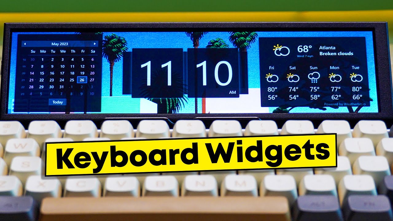
My Mini Monitor has been upgraded!
Mini Monitor V2 (Display Bar by Keebmonkey) https://www.keebmonkey.com/products/the-keebmonkey-display-strip?_pos=1&_sid=a6ab9582c&_ss=r
Mini Monitor on DROP: https://drop.com/buy/keebmonkey-display-bar?searchId=b77c61ea701c4bda3b6e28ca360c7cca&defaultSelectionIds=973410
Get Paperlike and support Work From Hy...

KeebMonkey
In Stock. The Keebmonkey Display Strip is an 8 Inch wide-screen display mini monitor. You are able to display anything you want on the display and enhance your work experience as well as your efficiency. The screen is nicely protected by the aluminum frame. The screen is not too big to take up the space of your desk se
meager girder
How do I find out exactly how many VCC ma I have for using the pins on a rpi4b ?
someone told me I had a 3.5ma fan and it could take 10ma to start it and I might not have enough m/a left for it. Which is a bit surprising considering the 3A usb-c connector for a pi and I just have a keyboard/mouse/wifi connected t the usbs and that shouldn't take all the leftovers mA and leave me nothing to run things... right ?
 fast bane
same deal as we already discussed before on mcus. Its a few mA for an IO pin, a few hundred mA for the power supply pins
 rotund pivot
A good quality 2.5A power supply can be used if downstream USB peripherals consume less than 500mA in total.
https://www.raspberrypi.com/products/raspberry-pi-4-model-b/specifications/
meager girder
fast bane
same deal as we already discussed before on mcus. Its a few mA _for an IO pin_, ...
Yeah that isnt what I was asking at all. I want to know the total consumption to know what is left
fast bane
then you have to math that yourself, the pi 4 is generally about 2A give or take but that fluctuates hugely based on if it is in sleep or not. How much your peripherals use depends on which peripherals, a cheap basic keyboard is often under 50mA but one with enough RGB to light up your room can hit an amp on its own
wraith grove
wraith grove
not sure if that was originally bitrot though
and now I have one that seems to be write-locked, but not obviously throwing errors when written to?
I've tried to dump octoprint onto it several times, and zero it out once, still boots the previous install after all that (overtly different from what I am trying to put on it)
turbid rivet
Does anyone have any experience with the Ox64? I’m considering the viability of creating a portable serial terminal with it and was wondering how much work people have done with it…
 solemn finch
turbid rivet
Does anyone have any experience with the Ox64? I’m considering the viability of ...
solemn finch
turbid rivet
Does anyone have any experience with the Ox64? I’m considering the viability of ...
I have a couple but haven't used them.
 misty ledge
I've been trying to get started with the Raspberry Pi high-quality camera. Is there a good, up-to-date "getting started" guide for it? I found a PDF called "The Official Raspberry Pi Camera Guide" with a publication date of 2020. However, it seems to be out of date, because it uses the raspistill and raspivid command, which are deprecated and have been replaced with libcamera-still and libcamera-vid.
There are a couple of things in particular that I'm trying to find out:
-
libcamera-still seems to take about 4-5 seconds worth of video, even though it only outputs a single still frame. Why is it taking so many frames? I was hoping for a command that would just take a single picture, more-or-less instantaneously.
-
Is there any reasonable, non-frustrating way to focus the camera on a headless Raspberry Pi? Right now, I'm taking a frame with libcamera-still (which takes 4-5 seconds, as mentioned), then I scp the jpeg to my laptop (which takes about 13 seconds over WiFi) and view it. Then I move the focus ring a little, and repeat the process. This isn't really great. Do I pretty much need to attach a monitor (and use the full, not "lite", version of Raspberry Pi OS) in order to make focusing practical?
 storm wagon
I forgot how I got mine to work but I know it uses libcamera and I'm using a phone app called RaspController to see through the camera. Works great, though I still need to take shots to make sure it's perfect.
 charred yacht
Does anyone have recommendations for free dynamic DNS provider? We have a game server and want to access it, done all the port forward stuff just need to get a domain name for it.
faint sparrow
charred yacht
Does anyone have recommendations for free dynamic DNS provider? We have a game s...
Cloudflare?
Also you can get free domains on register/amen
They also weirdly pay you to register domains
Although the cash out is about 3 months long
charred yacht
I've never heard of it
But I can understand why they do that
1 probably wanting to send/rent ipv4 addresses (good investment if you have the monies)
2 probably wanting to have bigger share of domains so they can challenge Google DNS
broken shuttle
Cloudflare is one of the biggest cloud providers there is. They do hosting, DNS servers, and the like, but they aren't as public-facing as Google and Amazon.
rotund pivot
and CDN
 ruby night
@torn frigate unfortunately, I have to go offline -- hopefully someone else can continue with help. Good luck.
BTW -- I have never had that blinkatest fail after following the guide 😉
 torn frigate
All good! I think I found the issue.
I'm using a 240x240 display and the driver may be conflicting
on the SPI
dtoverlay=spi1-3cs should work
 slate glen
so i got alpine linux running on my pi zero.. but i didn't realize it uses an in memory read only filesystem... how or what is the process for side loading packages and customizing the kernel
 upper wagon
Hey, question about fbtft. On non-rpi sbcs is it possible to install the fbtft devices thing on a kernel later than 5.4? Or like, how would you go about setting up the device overlays? I was taking a look at this and wondering if the memory registers within init would apply to the actual SBC itself or just the display
GitHub
WaveShare SpotPear 3.2" and 3.5/4.0" TFT LCD overlays for the Raspberry PI and PI 2 - waveshare-dtoverlays/waveshare32b.dts at master · swkim01/waveshare-dtoverlays
 spice kayak
Late but to add to the recommendation, cloudflared tunnel has been useful. It acts as if you have a vpn. For example you name your server mastodon.xyz.io and it sits at 10.0.0.10 then after you configure cloudflared with mastodon.xyz.io, your team can visit mastodon.xyz.io and cf handles the public facing IP address. You don't need to do anything to the 10.* or attempt to change your pf rules. Tunnel became a free product in 2023; which is why I didn't really explore it before.
torn frigate
My code is throwing an error ( "Adafruit_BME680_I2C' object has no attribute 'data_ready' error. ) and if someone out there could give it a once over for debugging I'd appreciate it. I'm a total novice at all of this.
For some background on what I'm doing - I'm choosing to only use the BME680s gas/pressure/altitude, and im basically ignoring the duplicate temp and humidity data since I have a SCD-41 already set up. I don't mind all of the data posting to the terminal, but I'm just choosing to transfer only the gas/pressure/alt. to ada.io.
steady rose
there is no data_ready. is that code example from somewhere?
torn frigate
The code was altered from a DHT temp/humidity sensor found on GitHub Adafruit. I don't have the link at the moment.
But yesterday, another member of the discord worked with me to transform it to work with the SCD4x
steady rose
libraries will vary. not all will have the same features, etc.
so the data_ready property won't be in everything
are you trying to rate limit the readings/posting of the data?
torn frigate
steady rose
there is no data_ready. is that code example from somewhere?
could I essentially omit this entirely?
torn frigate
steady rose
are you trying to rate limit the readings/posting of the data?
I have the limit set to every 15 seconds.
steady rose
you'll need to for the code to work, since as is, it's syntax error
torn frigate
Alright I just wasn't sure if it needed to be replaced by something or not.
steady rose
can use a simple time.sleep(15) to handle to data rate
torn frigate
steady rose
can use a simple `time.sleep(15)` to handle to data rate
It's in there nearing the bottom- you may need to hit expand on the txt
steady rose
ah, yep, ok, see it now
yep, so just remove the if bme680.data_ready conditional check
while True:
   read data
   send data to aio
   time.sleep(15)
and for read data with the bme680, no need to check a data_ready property
torn frigate
once I remove the if statement I would have to align the indentation under the while True, correct?
torn frigate
steady rose
that's basic python use of white space thing
Awesome- everythings working. I supposed I should have tried deleting it first, but I strongly (and wrongly) assumed that something else would need to take its place. All data is posting in the terminal and it's feeding into ad.io perfectly.
It is printing twice in the terminal but I'm sure I can figure out a fix there
I'll likely up the interval as well. Do you know the limit in seconds I can do?
steady rose
i think it depends on account level, like free vs. paid
should be shown somewhere on AIO
basic data rate = 30 / min
plus data rate = 60 / min
torn frigate
I'll assume I could make the output data once per 5 minutes, 10 minutes, hour, etc even? I'll just have to denote that in seconds.
steady rose
yep. the rate limit would work in the other direction - it would limit the fastest available post rate.
like can't do once per second with a 30 / min limit
for anything above the rate limit (slower posting rate), there is no limit
the only thing to consider there is data retention
basic = 30 days storage
plus = 60 days storage
 torn frigate
Once more question for you - what block would be best for outputting particle count data on the PMSA003I?
For example: you could have each reading (ie: .3um ,.5um ,1.0um, 2.5um, 5.0um, 10um) go into separate feeds. That may be the only way to do it anyways...
steady rose
yep, each in a separate feed.
upper wagon
Hey, question about fbtft. On non-rpi sbcs is it possible to install the fbtft devices thing on a kernel later than 5.4? Or like, how would you go about setting up the device overlays? I was taking a look at this and wondering if the memory registers within init would apply to the actual SBC itself or just the display
thin pelican
Hey guys.
Pi400 > cyberdeck hat > hyperpixel4
No current issues with the hat/hyperpixel problem. Pimoroni long since fixed that conflict but it's a kernel thing that's current only present in raspbian.
The point of the project was a little retro-ish cyberdeck. The problem is raspbian hates me and I want to build a kali or parrot for it, or even just a daily driver debian build with a good suite of tools installed is fine... but after a year of trying (maybe missing the obvious) I can't get kali/parrot/etc to push to the hyperpixel. Someone in the parrot discord suggested recently to use what's in the rpi kernel to build parrot but tbh that's over my head.
paper flower
thin pelican
Hey guys.
Pi400 > cyberdeck hat > hyperpixel4
No current issues with the hat/h...
For Raspian/RaspberryPiOS, have you tried this guy? https://github.com/pimoroni/hyperpixel4

GitHub
Driver for the Pimoroni HyperPixel 4.0" Touchscreen Display - GitHub - pimoroni/hyperpixel4: Driver for the Pimoroni HyperPixel 4.0" Touchscreen Display
paper flower
thin pelican
Hey guys.
Pi400 > cyberdeck hat > hyperpixel4
No current issues with the hat/h...
For Kali/Parrot, this issue likely applies: https://github.com/pimoroni/hyperpixel4/issues/140
Not sure what kernel changes are needed but, you may be able to do some more digging to find out.

GitHub
IT seems like the packages required are only available if you install stock Raspberry OS. I tried installing this on the 1.5 build of Pimiga (which I believe is Raspberry Pi OS lite) as well as mul...
thin pelican
paper flower
For Kali/Parrot, this issue likely applies: https://github.com/pimoroni/hyperpix...
How would I even ho about implementing that without breaking parrot
paper flower
That, I can't answer, unfortunately as I've not dug into that side of things for RPi. I would hope that the necessary changes are available in a mainline kernel (or loadable as modules) but, there is a possibility that you'd have to compile a custom kernel, including the needed changes from Raspian. What Pi version are you using? I might have some time to look into it on the weekend but only have a 3B+ handy.
zenith crystal
TIL - I was having issues with a couple of new Seesaw-based boards and changed the I2C baudrate (i2c_arm_baudrate=400000) and all the problems disappeared
i made a note of this in the forums, but i think this needs to be somewhere in the Pi FAQ maybe?
humble marsh
zenith crystal
TIL - I was having issues with a couple of new Seesaw-based boards and changed t...
you upped it from 100k to 400k?
zenith crystal
yes
i haven't tried it against my CRICKIT yet, but for both the new I2C Gamepad and NeoPixel boards, problems ☁️
zenith crystal
humble marsh
you upped it from 100k to 400k?
the CRICKIT Hat really likes that setting - i 3 servos and a stepper moving in orchestration smoothly
humble marsh
zenith crystal
the CRICKIT Hat _really_ likes that setting - i 3 servos and a stepper moving in...
That is interesting - I will pass this on.
 dusk flower
hello!
I was thinking... can I use the FireTV Ethernet adapter on the PWR port of the PiZ2?
humble marsh
dusk flower
I was thinking... can I use the FireTV Ethernet adapter on the PWR port of the P...
The power port does not support data transfer (https://raspberrypi.stackexchange.com/q/56768/27423). Whether the Ethernet adapter would work or not depends on whether its hardware is supported by Linux.
dusk flower
humble marsh
The power port does not support data transfer (https://raspberrypi.stackexchange...
ah, fuzzlenuggets :/
zenith crystal
dusk flower
ah, fuzzlenuggets :/
I AM STEALING THIS!
dusk flower
zenith crystal
I AM STEALING THIS!
good for you, I stole it from Ron Gilbert's Sam&Max Hit The Road 🤣
paper flower
Quick question for you on VESA specs, specifically DisplayPort (but I bet it's a blanket policy on all of em): Do you know what sort of policies/restrictions govern their use for open source projects? I know that x.org and likely Wayland have a good relationship with VESA and offer contributors limited access to the spec. My suspicion therefore is that implementation is OK (for those with access) but not original spec doc distribution. Does that sound right?
broken shuttle
It's... hard to say actually. I am a member through work, so I might be able to send them an email. What part(s) of the spec are you wanting to implement?
paper flower
I am planning to implement a USB-C DisplayPort AltMode source and sink, along with some signal processing. The overall goal is similar to what is now being billed as "spatial computing" after Apple's announcement - that is, taking one or more video signals, agnostic of source, and "placing" them in space around the user.
My implementation will be primarily FPGA based, for signal processing.
broken shuttle
Well, you have your work cut out for you then. DP is not simple to implement, let alone from scratch.
paper flower
I wouldn't think so. It should be a good learning experience, even if I don't succeed. I'm mainly from the "squishy" software engineering background so, will be working my way up to it through other implementations (probably first being MPI I3C Basic)
thin pelican
Anyone install bettercap on raspbian before
 thin grail
Hey guys. I was wondering if I can get some help with this

GitHub
Python script for the NEO-6M GPS module on the Raspberry Pi - FranzTscharf/Python-NEO-6M-GPS-Raspberry-Pi
I don’t fully understand code
I need it to give me gps coordinates that I can then transmit via radio
Ideally I need this done in the next hour or so
(i do have until tommorow but we need to test tommorow
import serial
import pynmea2
def parseGPS(str):
if str.find('GGA') > 0:
msg = pynmea2.parse(str)
print "Timestamp: %s -- Lat: %s %s -- Lon: %s %s -- Altitude: %s %s" % (msg.timestamp,msg.lat,msg.lat_dir,msg.lon,msg.lon_dir,msg.altitude,msg.altitude_units)
serialPort = serial.Serial("/dev/ttyAMA0", 9600, timeout=0.5)
while True:
str = serialPort.readline()
parseGPS(str)
I have found this but again
I dont full understnad it enough to modify it
rotund pivot
@thin grail I'm not much help on the Pi side, but just to make sure... is the GPS hardware on the Raspberry Pi RFM69 receiver and not on the RP2040 RFM69 sender? It would be a different library to run on the RP2040.
thin grail
rotund pivot
<@955190572170248252> I'm not much help on the Pi side, but just to make sure......
It’s on a separate pcb
I think I figured it out
Will test tomorrow
misty ledge
Does anyone know off the top of their head why the Raspberry Pi has five I2C buses:
crw-rw---- 1 root i2c 89,  1 Jul  9 19:31 /dev/i2c-1
crw-rw---- 1 root i2c 89, 10 Jul  9 19:31 /dev/i2c-10
crw-rw---- 1 root i2c 89, 11 Jul  9 19:31 /dev/i2c-11
crw-rw---- 1 root i2c 89,  2 Jul  9 19:31 /dev/i2c-2
I had thought it just had two I2C buses, and I thought bus 0 was reserved for use by VideoCore, so I had thought it might not show up under Linux. Really I was only expecting to find /dev/i2c-1
OK, it looks like i2c-10 is for the display and camera ribbon connectors. Still searching for what i2c-2 and i2c-11 are. I suppose it doesn't really matter, since I'm pretty sure the one I want (the i2c bus exposed on the 40-pin connector which is not reserved for the HAT EEPROM) is i2c-1.
 waxen valve
misty ledge
Does anyone know off the top of their head why the Raspberry Pi has five I2C bus...
waxen valve
misty ledge
Does anyone know off the top of their head why the Raspberry Pi has five I2C bus...
there is also a pinctrl i2c mux at play
where a single i2c controller is shared over multiple pins
what does ls -l /sys/class/i2c-adapter report?
misty ledge
waxen valve
what does `ls -l /sys/class/i2c-adapter` report?
lrwxrwxrwx 1 root root 0 Jul 10 19:16 i2c-1 -> ../../devices/platform/soc/3f804000.i2c/i2c-1
lrwxrwxrwx 1 root root 0 Jul 10 19:16 i2c-10 -> ../../devices/platform/soc/3f205000.i2c/i2c-11/i2c-10
lrwxrwxrwx 1 root root 0 Jul 10 19:16 i2c-11 -> ../../devices/platform/soc/3f205000.i2c/i2c-11
lrwxrwxrwx 1 root root 0 Jul 10 19:16 i2c-2 -> ../../devices/platform/soc/3f805000.i2c/i2c-2```

So I guess this is saying that `i2c-0` and `i2c-10` are reached via `i2c-11`?yeah, i2c-0 and i2c-10 are virtual controllers
when you try to use one, it will switch the gpio muxing around, and then i2c-11 does the real request
misty ledge
OK, thanks!
waxen valve
if you use i2c-11, youll wind up on a random set of pins
whichever of 0/10 was used last
misty ledge
OK, I did a little more digging, and I think I have it all figured out now:
/dev/i2c-1   available for user on 40-pin connector
/dev/i2c-2   HDMI connector
/dev/i2c-10  camera and display connectors
/dev/i2c-11 implementation detail for i2c-0 and i2c-10```(This is for Raspberry Pi 3, at least.)
waxen valve
i2c-2 also depends on if your using fkms or kms
with legacy or fkms, the firmware is in control of the hdmi i2c port
but with kms, linux is in control
thin pelican
Anyone have issues with usb ssh hanging on pizero?
broken shuttle
Sounds like a power issue to me (i.e. you need to plug it in to a powered hub that can deliver at least 2A to a single USB port).
thin pelican
broken shuttle
Sounds like a power issue to me (i.e. you need to plug it in to a powered hub th...
I thought maybe, since I'm plugging it into a pi400. Power bank didn't help.
broken shuttle
Uhh yeah you won't be able to power it directly from the Pi 400.
Every generation of full sized pi since the 2 has drawn more than is practical from USB. So drawing another amp or two isn't going to work reliably.
thin pelican
The other issue of course is that they designed the pizero so that only one usb port is accessible at a time
Idk who the genius that okayed that was. 🤷🏼♂️
 dusk grotto
Anyone know how I can format a 128gb to fat32 on raspberry pi os?
 humble nova
Im no expert, but isnt FAT32 up go 32GB and you'd need exFAT?
wraith grove
fat32 is not what I would use to host an os past windows 98 (and the 2-4G file limit is irksome)
humble nova
I understood the question as format FROM raspberry, not FOR hosting its OS, but definitely agree with the message above
waxen valve
rpi open firmware
zenith crystal
and since nobody else mentioned it in this channel - https://www.theregister.com/2023/07/20/slackware_turns_30/

Who needs a graphical desktop manager anyway?
(proud user of linux since Slackware 0.99 😈 )
dusk grotto
dusk grotto
Anyone know how I can format a 128gb to fat32 on raspberry pi os?
Hey so just a follow up on my question here I needed to use fat32 because a device I was working with only worked with fat32 not exfat I got it all working I used raspberry pi Imager to format it to fat32 (TLDR everything is now working)
dusk flower
humble nova
Im no expert, but isnt FAT32 up go 32GB and you'd need exFAT?
nope.
 dusk flower
dusk grotto
Anyone know how I can format a 128gb to fat32 on raspberry pi os?
dusk flower
dusk grotto
Anyone know how I can format a 128gb to fat32 on raspberry pi os?
# mkfs.fat -F 32 /dev/partition
dusk flower
dusk flower
`# mkfs.fat -F 32 /dev/partition`
or, you could install gparted if using desktop mode
broken shuttle
dusk flower
`# mkfs.fat -F 32 /dev/partition`
Should use mkfs.vfat to make sure long filenames are enabled.
dusk flower
broken shuttle
Should use `mkfs.vfat` to make sure long filenames are enabled.
I thought they'd be enabled with the -F 32 flag?
broken shuttle
Not necessarily.
dusk flower
broken shuttle
Not necessarily.
uhmmm man page for .vfat redirects fo .fat one, maybe the tools merged at some point?
https://github.com/dosfstools/dosfstools
apparently, .fat vs .vfat are indeed just compat symlinks

GitHub
dosfstools consists of the programs mkfs.fat, fsck.fat and fatlabel to create, check and label file systems of the FAT family. - GitHub - dosfstools/dosfstools: dosfstools consists of the programs ...
broken shuttle
Ah I see
dusk flower
so yes, one could use either .fat or vfat, and if explicit -F is not provided, it'll just assume the best FS suited for the partition.
nice to see they kept compat, tho.
helps with legacy install scripts.
 unkempt cave
anyone know how to make a copy of a pi's sd card or create an custom image file from adjustments you made?
i tried using win32 disk imager but since im using a 64gb sd card its making an image file that 64gb
unkempt cave
no i dont think so
broken shuttle
Well, clonezilla can definitely do it.
waxen valve
unkempt cave
i tried using win32 disk imager but since im using a 64gb sd card its making an ...
there are scripts like img-backup and pi-shrink for that
 tawdry nimbus
Question, I am trying to install an Adafruit Mini PiTFT - 135x240 on a raspi zero. However, I keep getting an error message “apt failed to compile st7789v drivers!” Any ideas on how to fix?
tawdry nimbus
I followed the instructions on the product page and seem to be stuck. any advice would be appreciated
 rancid kindle
tawdry nimbus
I followed the instructions on the product page and seem to be stuck. any advice...
rancid kindle
tawdry nimbus
I followed the instructions on the product page and seem to be stuck. any advice...
Did you go with the pure python approach or the kernel module?
rancid kindle
tawdry nimbus
I’ll check back in soon.
it'd help if you could post what command you ran that gave that error, too 🙂

 crisp lion
Hello everyone 😄 , hope this is the right thread to ask my question
I generate different LED patterns based on (real time) user input. Is there a graph/ formula for calculating the time needed to write to the whole strip based on how many LEDs it has?
I'd like to know what's the maximum amount of LEDs I could get away with until the write operation takes too long and it doesn't feel snappy/ real-time-y enough
zenith crystal
crisp lion
Hello everyone 😄 , hope this is the right thread to ask my question
I generate ...
"it depends" on what hardware you're using - for example i can use the I2C Neopixel driver board and write to a .5m strip every 2ms or so, which is about 50x faster than human reaction speed
crisp lion
I have the strip connected directly to a pin on a raspberry pi 4 (one of them PWM pins by the way)
zenith crystal
still should be "stupid fast" - this is running via i2c (crickit hat) with a 50ms delay
crisp lion
thanks! The reason I am asking is because I'd like to place an order for the circuit to be made and I need custom spacing between the LEDs
and would hate to ask for too many and cause a delay 😅
zenith crystal
i don't know about wiring the WS28xx LEDs together personally, but the strip from Adafruit works just swell 😀
crisp lion
anyways, would the graph and the function be linear? how many LEDs until it takes 0.1 - 0.15s to write to the strip?
yeah, I have the 2812b I think, very happy with it 👍
zenith crystal
.1 second is a LONG time, so i wouldn't worry too much about it
i had sub 10ms writes for 30 LEDs easy
crisp lion
ah, nice!
then it looks like 400-500 LEDs would be the max
and 600 would be pushing it a bit too hard 😅
currently at just below 300, but will experiment and report back
zenith crystal
that's... a lot lof LED's 👀
crisp lion
yeah I know, I'm a little weird like that
 clever moon
hi i was trying to use this:https://learn.adafruit.com/adafruit-pca9548-8-channel-stemma-qt-qwiic-i2c-multiplexer i2c multiplexer with my raspberry pi 4 but when i try yhe first example code for it after installing blinka and the library for it i get this error File "<string>", line 16, in <module>
File "/usr/local/lib/python3.9/dist-packages/adafruit_tca9548a.py", line 62, in try_lock
self.tca.i2c.writeto(self.tca.address, self.channel_switch)
File "/usr/local/lib/python3.9/dist-packages/busio.py", line 203, in writeto
return self._i2c.writeto(address, buffer, stop=stop)
File "/usr/local/lib/python3.9/dist-packages/adafruit_blinka/microcontroller/generic_linux/i2c.py", line 52, in writeto
self._i2c_bus.write_bytes(address, buffer[start:end])
File "/usr/local/lib/python3.9/dist-packages/Adafruit_PureIO/smbus.py", line 303, in write_bytes
self._device.write(buf)
OSError: [Errno 121] Remote I/O error

Adafruit Learning System
Use up to 8 same-address I2C devices connected to one microcontroller with zero soldering!
i cant seem to figure out the problem
the multiplexer seems to be turned on because i see a small green led
 midnight flume
the small green led on the multiplexer means the module is getting 3V power. it's a power LED.
zenith crystal
it means you can't write to the I2C bus or there's nothing "attached" - what does /sbin/i2cdetect -y 1 return?
 midnight flume
double check the pin connectors and make sure they're not bent. they're small and it's possible to squish one to the side if not properly inserted which can cause IO failures.
Unless you're soldering to the I2C pins directly?
clever moon
its soldered on the multiplexer side and inserted into a breadboard on the raspberry pi side
steady rose
can you post a photo of this setup?
midnight flume
ok and you're sure SDA and SCL are wired correctly? a picture of your setup could help.
jinx
steady rose
no addresses are showing up in the i2c scan, so most likely a connection issue
midnight flume
if it's not scanning then the module i2c address itself isn't connecting. an i2c scan might help figure out if the board itself is connecting correctly before scanning for multiplexer channel scans.
steady rose
yep. the address of the PCA itself should always show up in the scan, regardless
clever moon
the first one is the multiplexer so the red is vcc, white is - , brown is scl, blue is sda, and green is rst (rst not connected to anything)


its also probably a 10 foot cable between the pi and the multiplexer
steady rose
cable length could be an issue
thanks for photos
can you post one showing soldering on back side here:

and how are the wire splices being made under the blue tape? are they soldered?
 steady rose
do you happen to have one of these cables?
https://www.adafruit.com/product/4209
if not, what all do you have in the way of STEMMA QT cables?
clever moon
 steady rose
thanks. that soldering looks fine.
 clever moon
i bought some ones on amazon from sparkfun to connect all the sensors to the multiplexer board but i soldered the wires directly on the multiplexer
steady rose
if you have a spare STEMMA QT cable, could try connecting the PCA to the Pi via this connector:

and then run the i2c scan again and verify the PCA address shows up
steady rose
also - good idea to remove all the things connected to the PCA outputs for now
first - just want to see if we can get the Pi to even see the PCA
via i2c scan
clever moon
ok sounds good
steady rose
i just connected one to a pi. here's what the scan should look like. the expected address is 0x70
 rancid kindle
@clever moon did you enable I2C on the Raspberry Pi using raspi-config?
rancid kindle
clever moon
yes i have
have you tried running the program as root? You shouldn't need to and if it's a permissions issue I'd expect different errors, but just in case...
clever moon
unfortunatley still nothing
waxen valve
clever moon
unfortunatley still nothing
what command are you running?
clever moon
i guess there must be something wrong with the board because when i connected a stmma cable to the other end of the multiplexer and attatched my smaller multiplexer i had bought the smaller one is being recognized
 clever moon
does anyone know how i can read https://learn.adafruit.com/adafruit-stemma-soil-sensor-i2c-capacitive-moisture-sensor with the multiplexer

Adafruit Learning System
Keep your plants happy with an I2C temperature/moisture sensor
like how do i use the multiplexer to communicate
ive tried but i cant seem to figure it out
nvm i got it working
 rigid abyss
I'm curious about reading the magnetometer on a bno085 with python on a rpi via i2c.
I have it wired correctly and see 0x4a when I run i2cdetect. But when running the sample code or other code, it's unable to read the magnetometer.
umbral sable
rigid abyss
I'm curious about reading the magnetometer on a bno085 with python on a rpi via ...
Do you get an error, zeroes, or nonsensical values?
rigid abyss
OSError: [Errno 121] Remote I/O error
The address and everything else is correct according to the documentation.

Here it is, the motion sensor you were looking for: the one that just gives you the directly usable information without requiring you to first consult with a PhD to learn the arcane arts of ...
As listed here
steady rose
rigid abyss
OSError: [Errno 121] Remote I/O error
try adjusting the pi's i2c bus clock speed:
https://learn.adafruit.com/adafruit-9-dof-orientation-imu-fusion-breakout-bno085/python-circuitpython#python-computer-wiring-3072324
NOTE: The BNO85 seems to work best on the Raspberry Pi with an I2C clock frequency of 400kHz
 sweet gorge
hi all, I need general linux help
this doesn't necessarily apply to RPi's but I'm at the point of "ask strangers on the internet" as I'm now days into messing with systemd
and ChatGPT helped a lot, but then ChatGPT did what it is want to do and stopped being helpful
 frail spindle
sweet gorge
this doesn't necessarily apply to RPi's but I'm at the point of "ask strangers o...
frail spindle
sweet gorge
this doesn't necessarily apply to RPi's but I'm at the point of "ask strangers o...
don't ask to ask, just ask :)
zenith crystal
(I seem to be pointing to other people's answers today... 😃 )
sweet gorge
Fair point, apologies.
I am currently trying to get a shell script to run at launch that puts minecraft into a screen and that is about it, it runs fine when manually executed. I've tried just about every approach to writing the service file and still end up with it doing absolutely nothing, the logs just say "failed" because it retried 10 times, I've put in a sleep timer and done all the magical voodoo. I'm beginning to think that calling for screen is the problem, and I am unsure if I just point to executing java and being clear on launching spigot (minecraft server client).
I am an AWS architect by trade, and this is the first time systemd hasn't been doing a simple task, which has thrown me for a loop because it's intrinsically point and shoot for all the development I do. So this is murky territory.
zenith crystal
ah - you have to have X (or Wayland) running first, which actually doesn't occur during service execution phase
sweet gorge
no X, this is an AWS EC2 instance.
zenith crystal
"screen" requires an X server
sweet gorge
screen itself is just so you can park an application in the background and recall it to terminal
frail spindle
Wait
zenith crystal
screen is "text"
frail spindle
You have screen
sweet gorge
si
frail spindle
On a shell script
sweet gorge
yeah, work's just fine
frail spindle
that is supposed to be launched by a systemd service
Systemd services do not have an interactive console, terminal, etc
So, I doubt screen is going to work
zenith crystal
are you trying to run the minecraft server or client?
frail spindle
You will need to manage your server with a pidfile or something
zenith crystal
regular minecraft is a graphics-based program and requires X or equivalent to run - screen is just a text-based multi-terminal like program and also needs at least a console output
zenith crystal
do you have any error output? what does systemctl status <your service name> say?
note, i've not ever done this but a quick search turned up the nogui option ...
sweet gorge
yeah I am runing the proper launch
as it will run on it's own just fine in the start.sh script i made
zenith crystal
hmmm - i found something else useful i think - https://gist.github.com/dotStart/ea0455714a0942474635

Gist
Systemd services for Minecraft Servers. GitHub Gist: instantly share code, notes, and snippets.
sweet gorge
LAWDY LAWDY
zenith crystal
just regular search, amigo
rigid abyss
steady rose
running this example?
<https://github.com/adafruit/Adafruit_CircuitPython_BNO08x...
That ended up working. I updated the references in my script and it worked. Thanks
 shy saffron
Anyone know if it's possible to access the rPi's USB bus from the GPIO header? Doesn't look like it but figured I would ask.
turbid rivet
shy saffron
Anyone know if it's possible to access the rPi's USB bus from the GPIO header? D...
Nope, not possible through the 2x20.
waxen valve
shy saffron
Anyone know if it's possible to access the rPi's USB bus from the GPIO header? D...
the usb bus has its own dedicated pair of pins, D+ and D- on the soc, that have no relation to the gpio header
shy saffron
waxen valve
the usb bus has its own dedicated pair of pins, D+ and D- on the soc, that have ...
It has pins for D+/D- exposed?
waxen valve
for the pi4(00), zero and model-a's, the D+/D- are directly exposed at a usb port
for the 1b/2b/3b, there is a usb hub connected to those pins, and you cant access them directly
 opaque wagon
I'm doing an I2C dump of an Arduino being a peripheral device on the Raspberry Pi, and there are random 0x80s everywhere - is this a sign of the bus capacitance being too high since it can't pull down the line fast enough?
Funny thing is that is my logic analyzer is read the signals just fine (no 0x80 in pulseview)
(The cable is a bit long - an Adafruit T-Cobbler through a level shifter to the other side of the breadboard)
Here is a picture of the I2C dump (the number of 0x80s change every dump)

And here is PulseView

ok slowing down the I2C bus "fixed" the problem!
umbral sable
In the Pulseview graph, the short clock pulse right at the start of the read operation looks a bit suspicious. Possibly the slave is clock-stretching on the response because it couldn't respond fast enough to the read command.
But slowing down the bus helps with all sorts of potential issues.
waxen valve
the rpi also has a clock stretching bug

GitHub
Describe the bug I'm having intermittent problems with the RPi4 when it performs I2C reads on devices (like UCD9081 texas) that use clock stretch. This apparently affects the Raspberry Pi and w...
Recollection is that only the new controllers are fixed in case it broke something else. In each case there is a pin muxing option to map a new controller onto the pins of BSC0 or BSC1. (BSC6 in the case of GPIOs 0&1 alt5, or BSC3 for GPIOs 2&3 alt5).
from what i remember (and skimmed over here), the i2c controller in the vc4 era (pi0-pi3) had this bug
on the bcm2711, they fixed it on the new controllers, but didnt want to risk causing new problems
so they left the old i2c controllers broken
 ionic fable
So I am trying to install witty pi hat l3v7 onto my pi 4 and it installed fine, but my pi still cant find the directory
 crisp drift
Anybody got experience with using circuitpython neopixel sudo-less on raspberry pi 3? https://docs.circuitpython.org/projects/neopixel/en/latest/#setup-for-sudo-less-usage-on-raspberry-pi-boards
I've tried the aforementioned steps, as well as giving the group gpio access to /dev/mem, but nothing works.
 broken shuttle
Did you log out then back in?
broken shuttle
Oh, you'd have to set that via udev. You can't just change permissions for things in /dev since those are populated during runtime and are not real files.
Did you add yourself to the gpio group?
crisp drift
crisp drift
I might just try using setuid or something
Can't get it to work either
waxen valve
crisp drift
Can't get it to work either
what is the actual permissions error? run it under strace
crisp drift
 waxen valve
crisp drift
I might just try using setuid or something
waxen valve
crisp drift
I might just try using setuid or something
scripts cant be setuid root
setuid only works on compiled binaries
crisp drift
Ah that's stupid from me then
waxen valve
why does this library need to open /dev/mem ?
crisp drift
I think to write to the LED? It's on pin board.D18
crisp drift
I thought that was weird as well, but I don't think I'm doing anything weird
 waxen valve
where is the source for that neopixel library?
crisp drift

GitHub
CircuitPython drivers for neopixels. Contribute to adafruit/Adafruit_CircuitPython_NeoPixel development by creating an account on GitHub.
waxen valve
and then neopixel_write?
crisp drift
What do you mean?
waxen valve
i think the problem, is because its using the hardware pwm, in serializer mode
and there is no proper driver in linux to allow that from non-root
crisp drift
Okay, I'll try to just use root then
turbid rivet
crisp drift
I think to write to the LED? It's on pin board.D18
According to https://learn.adafruit.com/neopixels-on-raspberry-pi/raspberry-pi-wiring, you may have to disable audio to access gpio18.
zenith crystal
is your user in the gpio group?
waxen valve
zenith crystal
is your user in the `gpio` group?
that wont help with /dev/mem, which isnt owned by gpio
waxen valve
turbid rivet
According to https://learn.adafruit.com/neopixels-on-raspberry-pi/raspberry-pi-w...
yeah, analog audio also uses PWM
the pi0-pi3 only have a single PWM controller, and both channels are used for left+right
zenith crystal
hm - i just ran a PWM servo off of D18 without any problems
on a Pi 3
oh - did you add dtoverlay=pwm,pin=18,func=2 to the /boot/config.txt
also, i just looked at the the Neopixel code and it's setting up the pin parameter as a digital I/O port, not PWM self.pin = digitalio.DigitalInOut(pin) self.pin.direction = digitalio.Direction.OUTPUT
and the error says "SPI transfer error" - i have SPI turned on via the config - maybe that's the difference?
crisp drift
SPI transfer error happened when I tried using the SPI pin, according to the first link I sent. I think that is a different problem than the /dev/mem, which happens when I use the normal pin
crisp drift
zenith crystal
oh - did you add `dtoverlay=pwm,pin=18,func=2` to the `/boot/config.txt`
also...
I didn’t add that to the boot config, should I?
zenith crystal
well, it won't hurt
crisp lion
hi guys I have a quick question;
let's say I have a neopixel strip with 1000 LEDs on it
but only want to use 100 LEDs and that's what I pass in as the second argument when instantiating the NeoPixel class, e.g. NeoPixel(board.D12, 100)
would the 900 dormant LEDs cause any write delays or will it be as fast as if there were only 100 LEDs in the strip?
turbid rivet
Not if you’re using the first 100 LEDs.
crisp lion
turbid rivet
Not if you’re using the first 100 LEDs.
excellent, thanks!
yeah, it's always going to be the first 100 or whatever the number
turbid rivet
Your hardware doesn’t really ever see your neopixels, it just spits data into the input. The first pixel takes that data, eats the first pixel’s worth of data, and passes the rest out its output to the next, and the process repeats.
If you only send 100 pixels’ worth of data, the 101st pixel never gets any data, so it sits idle until it does.
crisp lion
ah nice! Good to know, thanks!
By the way, seems like you know a lot
so I'd like to ask you another question
I have certain LED light patterns created based on real time user input
I was wondering what would the maximum number of LEDs in a strip be possible for the write to take 0.1s?
is there like an x/y graph that has latency as a function of the number of LEDs in a strip?
Would that function be linear?
(I sure do hope it's not a quadratic lol)
turbid rivet
Neopixels are typically sent data in a fixed frequency stream of 800KHz, so one pixel takes about 10us per color channel. 100 RGB pixels would require ~3ms for a single data transfer, and 1000 RGBW pixels would require about 40ms.
The sending of data to neopixels is basically linear, though the more significant delays generally come from more complex computation of which pixels are assigned what colors in your software.
crisp lion
oh right; I have the ws2812b
yeah, that's exactly what I have discovered... 😅
so you're 100% correct
So I'd be looking at about 333 LEDs for a 0.1s reaction time?
turbid rivet
Assuming the only constraint is the transmission speed of the data, you’re probably off by a factor of 10.
crisp lion
great! 33.3 LEDs it is 🤣
turbid rivet
More like 3333.
crisp lion
oh wow!
that's great
In any case, I'm just curious; the neopixels are on a single strip, so it kind of makes sense that the data signal has to go through them all (like going through a list of data)... But is it possible for the data to be sent only/ directly to the pixel that needs it?
as in... accessing a pixel like you would data in a hash map rather than having to loop through a list of data
turbid rivet
Nope. Hardware limitations.
crisp lion
 turbid rivet
From a software perspective, you can change a single pixel however you like, thanks to the abstraction layer the adafruit libs provide
crisp lion
turbid rivet
From a software perspective, you can change a single pixel however you like, tha...
Correct, but the write still goes through the entire strip...
turbid rivet
Exactly.
crisp lion
so it's not like I'm saving any time
turbid rivet
Again, writes are generally not the primary constraint.
crisp lion
I understand; but it's still great news for me; I thought the max was 333 LEDs and not 3333 LEDs
I'm not great with the mini/ mili/ micro/ nano etc unit prefixes so that's why I was off by x10
Right, so given this excellent number which is 10x higher than I expected
if my real-time user input system is choking and LEDs are flickering/ lagging whatever, it means that my program sucks rather than hardware?
waxen valve
turbid rivet
From a software perspective, you can change a single pixel however you like, tha...
this is where i can see some DPI abuse coming in handy
with the DPI hardware on the rpi, you can hw accelerate writing to 24 neopixel strings at once
with 24 seperate strings, an example set of 3333 LED's, becomes 24 sets of 138 or 139
so, it now only takes ~139 writes to update the entire set, rather then 3333, 1/24th the update time, or 24x the refresh rate
crisp lion
wooooow that's excellent!
now... could I do that splitting on a raspberry pi? I'm not even sure they have 24 pins
waxen valve
https://github.com/librerpi/rpi-tools/blob/master/utils/kms-test.cpp#L33-L55
some unfinished test code
crisp lion
wow!
waxen valve
it would be using 24 of https://pinout.xyz/pinout/dpi these pins
specifically, the 8 red/green/blue ones
crisp lion
@waxen valve would it be ok if I DM'd you?
waxen valve
lets keep it here, so others can also read it later if they want to do the same
waxen valve
basically, the DPI on the rpi takes a "frame" of "pixels", each pixel is 32bits, containing 3 sets of 8bit color, and 8 wasted bits
under normal conditions, it drives something like https://shop.pimoroni.com/products/hyperpixel-4-square?variant=30138251444307

A uniquely square, high-resolution, high-speed, 4.0" display with optional touchscreen for Raspberry Pi – it's hip to be square!
but all its really doing, is taking 24bits out of an array, presenting it on 24 pins, waiting 1 clock cycle, and repeating
who says you cant put a stream of neopixel commands into bit0 of each pixel?
who says you cant put 24 seperate neopixel commands, one stream into each bit
turbid rivet
It’s a little more complicated than that, but that is possible.
waxen valve
one limitation of the hardware, is that while hfront and hbackporch can be 0, hsync has a minimum of 1
so, at least 1 "pixel" out of every scanline has a 0 for all 24 bits
and same in the vertical, vfront and vback can be 0
but vsync has a min of 1, so for 1 full scanline, all 24 bits will be 0
but you can freely decide what the w and h are, up to 2047 i think
turbid rivet
But hey, if you’re using 24 lines, and each scan line is what, 640px across? That’s a lot of pixels
waxen valve
the example config on https://github.com/librerpi/rpi-tools/blob/master/utils/kms-test.cpp#L24-L32 assumes fkms
but kms allows you to specify video timing params, so you could streamline this more
turbid rivet
I guess the better question is, does your application need this level of hardware hacking to do what you want it to do?
waxen valve
turbid rivet
But hey, if you’re using 24 lines, and each scan line is what, 640px across? Tha...
but keep in mind, that 620 pixels in the framebuffer, is 640 samples of a serializer
so, the neopixel protocol, what does it take to write to one pixel?
turbid rivet
24 bits @ 800KHz
turbid rivet
Yup

 turbid rivet
Honestly, if you need a decent frame rate on a large display of pixels, it’s much easier to use dotstars or hub75
waxen valve
assuming you can fudge the timing some
lets make a DPI pixel last 0.4 uSec
a single bit, is 3 pixels, 100 for a 0
110 for a 1
so 24 bits, is 72 samples/pixels
a 2016 pixel scanline, contains color data for 28 neopixels
then you have a stray 0.4uSec pulse, that might confuse things...
if you use all 24 bits of "color", with a 2016 pixel scanline, thats 672 neopixels refreshed, in just 1 scanline
crisp lion
Hmmm this is a bit hard for me to understand to be perfectly honest 😅
waxen valve
and handily, the vsync pulse will get interpreted as the reset
waxen valve
crisp lion
Hmmm this is a bit hard for me to understand to be perfectly honest 😅
yeah, the hard part here, is writing the code to do this
but some very rough math, says you could refresh 1,344,000 neopixels in a single command on the dpi
crisp lion
lol
waxen valve
and such a refresh, would only take 0.067 seconds
so, you could update such an array at ~14 fps
crisp lion
right... I'll definitely keep the conversation up till now in mind, but could we go back to normie land for a sec 😅 ?
waxen valve
yeah, the problem, is getting neopixels into the hands of somebody that can write this code, and making it easier for the avg user
i should probably get a heap of neopixels at some point, and try that
crisp lion
going back to what you mentioned about writing to 24 strips of neopixels at once...
I thought I could use only one PWM pin on a rpi at a time
waxen valve
the PWM controller can drive 2 pins at once
the DPI controller can drive 24 pins, and can also be abused to control neopixels
crisp lion
waxen valve
the PWM controller can drive 2 pins at once
I've heard people mention issues when using more than one PWM pin on a rpi 😢
speaking of DPI abuse... Is there an un/official library that would let me use Neopixels on DPI pins?
waxen valve
from what i know of the pwm controller, it can do 2 pins at once
waxen valve
crisp lion
speaking of DPI abuse... Is there an un/official library that would let me use N...
not currently, somebody would need to write one first
crisp lion
waxen valve
not currently, somebody would need to write one first
c/ c++ land?
waxen valve
turbid rivet
24 bits @ 800KHz
oh, and looking closer at the diagram, the bits differ from 110 and 100, the start/end never change
so encoding a color into the pixels, only involves updating the middle bit
waxen valve
crisp lion
c/ c++ land?
yeah, just c will do
if you know C, have a logic analyzer or scope, and some time, you could do it
crisp lion
too bad I have neither 🤣
crisp lion
waxen valve
yeah, just c will do
tell you what, I'll sit down and have a proper look at it; if you get a weird looking DM one day, it's probably going to be me
waxen valve
my scope isnt able to handle usb2 speeds (480mhz), but i was able to get usb working, with enough blind guessing
without a scope/la, you just have to assume the code is working, and then guess when it doesnt work
crisp lion
thanks for all the answers and getting involved, appreciate it guys @turbid rivet @waxen valve
waxen valve
an even more working-blind case, i could write all of the neopixel code, test it with a scope, and never actually test it on real neopixels
and then see what happens when somebody else runs it for the first time, heh
crisp lion
waxen valve
and then see what happens when somebody else runs it for the first time, heh
aight, I'll get a hazmat suit just in case heh
 ornate bluff
anyone know why a raspberry pi 4 would be hitching over SSH on a local network
waxen valve
ornate bluff
anyone know why a raspberry pi 4 would be hitching over SSH on a local network
wired or wifi?
ornate bluff
wifi but not much else going on on the network
waxen valve
there have been issues with the wifi power savings stuff
if you run ping pi4 in another terminal, does the ssh get better?
leave it pinging
ornate bluff
Yeah it seems like it. Interesting
waxen valve
the way its supposed to work, is that when the wifi is idle, client basically just turns the radio off entirely
and the router will hold packets for a few seconds
ornate bluff
but the pi is over aggressive in turning off?
waxen valve
and the radio will come back on every now and then, to check in
https://forums.raspberrypi.com/viewtopic.php?p=2125307 has directions on turning it off entirely
then you dont need ping to keep it awake
ornate bluff
hm I'm planning on using ethernet anyway eventually I was just setting it up at my desk and trying to figure out why it was acting off. That makes sense, thanks!
 paper carbon
bit of a doozy here, but
I'm running a pi with a pitft, and it runs a single fullscreen GUI, like a point of sale / kiosk
right now, it runs on a full X11 stack using LXDE, but I'd like to run it as "minimally" as possible
is there an easier way to configure this (like, a wayland / X11 compositor built for kiosk apps or such)?
and, is it possible to get this running in docker? (prefferably the display server as well)
the gui is built with Java Swing
i think i might've found the answer to my first question
https://www.raspberrypi.com/tutorials/how-to-use-a-raspberry-pi-in-kiosk-mode/

Kiosk mode on your Raspberry Pi allows you to boot straight into a full-screen web page or an application without using the desktop environment.
paper carbon
is it possible to run the pitft on wayland?
i can install weston, but it hangs at initializing drm backend
I'm not too familiar with how the linux kernel, wayland, and x11 work together
ornate bluff
Is there a way to share the Wifi from a raspberry pi with the ethernet port in a way that allows other devices on the Wifi to access the ethernet device?
waxen valve
ornate bluff
Is there a way to share the Wifi from a raspberry pi with the ethernet port in a...
setup NAT or routing between those 2 interfaces
ether routed or bridged, depending on your preference
ornate bluff
Hmm, I'll try using that bridge guide but reversing the interfaces
The guide says that there's no need to add wlan0 to the bridge since the AP package will do it, but I'm using the wlan0 as a client, not an AP, so would I just add it with an identical file to the one for eth0 but with wlan0 instead?
ornate bluff
Well so it turns out the Pi doesn't support bridging wlan0, but you can use proxy arp to do it but it requires setting up systemd-networkd. for whatever reason every time I try to do so, the pi never connects to the network (or it does and doesn't allow SSH/ping). i don't have a way to see the display of the pi, how can I figure out what's going on? is there a better way?
 uneven solstice
Hi, I'm trying to set up an ili9486 display on an Orange Pi Zero 3. I'm following this guide: https://learn.adafruit.com/circuitpython-on-orangepi-linux/orange-pi-r1 (I'm aware it's a different board). So far, i2c and SPI are set up (had to edit a file to make SPI work), but the digital pins aren't working, as it's giving an error (this is the code on the page, only change was to use a pin that the board has):
$ /home/orangepi/.mambaforge/envs/ili9486/bin/python /home/orangepi/testeBlinka.py
Hello blinka!
Traceback (most recent call last):
  File "/home/orangepi/testeBlinka.py", line 8, in <module>
    pin = digitalio.DigitalInOut(board.PC10)
  File "/home/orangepi/.mambaforge/envs/ili9486/lib/python3.10/site-packages/digitalio.py", line 165, in __init__
    self.direction = Direction.INPUT
  File "/home/orangepi/.mambaforge/envs/ili9486/lib/python3.10/site-packages/digitalio.py", line 195, in direction
    self._pin.init(mode=Pin.IN)
  File "/home/orangepi/.mambaforge/envs/ili9486/lib/python3.10/site-packages/adafruit_blinka/microcontroller/generic_linux/libgpiod_pin.py", line 55, in init
    self._line = self._chip.get_line(int(self._num))
  File "/home/orangepi/.mambaforge/envs/ili9486/lib/python3.10/site-packages/gpiod/libgpiodcxx/__init__.py", line 201, in get_line
    raise IndexError("line offset out of range")
IndexError: line offset out of range
As I have to set the DC and RST pins, I'm being unable to use the display. OS is Ubuntu 22.04 from the Orange Pi site, as it seems there is no Armbian image for this board yet.
uneven solstice
I'm trying to get i2c-2 working on Orange Pi Zero 3, I have enabled the overlay and i2cdetect detects the i2c device, but board says the board does not support it
Is the CircuitPython board still supported?
steady rose
uneven solstice
Is the CircuitPython `board` still supported?
try accessing it using this library:
https://github.com/adafruit/Adafruit_Python_Extended_Bus
uneven solstice
steady rose
try accessing it using this library:
<https://github.com/adafruit/Adafruit_Pytho...
I made a workaround before editing the busio.py, hardcoding the values of i2c-2, which worked but I wasn't happy with.
This library worked, thank you
waxen valve
@midnight flume https://github.com/librerpi/rpi-tools/blob/master/android-auto/main.cpp#L348-L366
ah found it, it was called gadgetfs
// Specific to controller
#define USB_DEV "/dev/gadget/fe980000.usb"
#define USB_EPIN "/dev/gadget/ep1in"
#define USB_EPOUT "/dev/gadget/ep4out"
by opening files like this, you can do usb device stuff from linux userland
in theory, tinyusb could be ported to that, and run under regular linux
midnight flume
all greek to me, i haven't even booted up a pi in about 3 years. no sense in tagging me for a discussion about pi's. 😉
waxen valve
ah
 frail sigil
noob question, i'm trying to figure out how to run an adafruit example on RPI for the RGB matrix displays... i'm in the current directoy of /rpi-rgb-led-matrix/examples-api-use but i'm unclear on how i actually execute one of the examples?
 vocal lava
frail sigil
noob question, i'm trying to figure out how to run an adafruit example on RPI fo...
vocal lava
frail sigil
noob question, i'm trying to figure out how to run an adafruit example on RPI fo...
Looking at the guide page at https://learn.adafruit.com/adafruit-rgb-matrix-bonnet-for-raspberry-pi/driving-matrices, it looks like one example is: sudo ./demo -D0 --led-rows=16 --led-cols=32 (change the rows and columns to your actual display)
rpi-rgb-led-matrix/bindings/python/samples should have python examples, too
frail sigil
thank you!
 crystal jewel
G'day all - just wondering if anyone has any experience with
- Witty Pi 4 L3V7 - RTC & Power Management for Raspberry Pi (https://www.adafruit.com/product/5705)
- PiJuice Zero https://uk.pi-supply.com/products/pijuice-zero
and would like to share their experience?
One thing I am concerned about is the Witty monitors the TXD pin to determine if the Pi is powered up - this is done by monitoring a the pin through a diode and smoothing cap, in theory allowing UART comms to still work; I am wondering if anyone can confirm this works as expected, as my primary case will be to add a pHat that requires UART i want to be sure it will work
the Witty is cheaper than the PiJuice - by a fair margin where I live; I wonder whether there is anything that is better in the PiJuice to warrant the price? I do like that the PiJuice uses fewer pins, and the UART conflict won't happen - but their documentation is a little confusing, so I have other concerns - my use case is to build a fully off grid system that runs purely on battery, but has scheduled power on / off. I am assured by PiSupply that it will work, but their docs say
*The PiJuice provides an onboard intelligent on/off switch allowing you to have control on when the Raspberry Pi will be switched on or off without having to plug or unplug the PSU as you would normally have to do.
Note: Turning on the Raspberry Pi via the onboard intelligent switch only works when the power is provided to the micro USB on the PiJuice.*
(https://github.com/PiSupply/PiJuice#power-management) - however it appears the docs assume you are running the system as a UPS, and not 100% battery powered. But i am assured that if the battery has enough juice, then it will work as required...
a second question I have, i need a short micro-usb <-> micro-usb cable; however all I can find are OTG cables - might be a stupid question, but is there anyting preventing you from using an OTG cable as an ordinary USB data/power cable?
I am looking at this cable specifically: https://thepihut.com/products/micro-usb-to-micro-usb-otg-cable-10-12-25-30cm-long
the use case is to connect a modem pHat to a pi-zero; so micro usb - micro usb is required
 rigid canyon
I'm using an adafruit pi-tft 2.2" with a raspberry pi 0 and I have the little 2.2 tft display at 270 deg. however I 'd like the set HDMI mirrored at 90 deg. Is this possible?
turbid rivet
rigid canyon
I'm using an adafruit pi-tft 2.2" with a raspberry pi 0 and I have the little 2....
See https://www.raspberrypi.com/documentation/computers/configuration.html#rotating-your-display for configuration options in your config.txt file.
The official documentation for Raspberry Pi computers and microcontrollers
turbid rivet
crystal jewel
a second question I have, i need a short micro-usb <-> micro-usb cable; however ...
Micro usb is for devices, otg is for hosts. That’s why there is no micro usb to micro usb unless one end is OTG, which is exactly what you need to connect a pi zero to a usb device.
waxen valve
ive not seen any micro to micro cables
i would just use an otg->a adapter, and then an a->micro cable
but from what i know, they should exist
broken shuttle
waxen valve
ive not seen any micro to micro cables
And I hope I never do see one.
turbid rivet
He did, in fact, link that particular micro to otg cable in his own message.
waxen valve
but now the fun part
how do you know which end is host and which is device? 😄
As of Oct 20, 2019 we have the ID pin on the MicroUSB connector tied to GND on both ends, this will help some hosts to force them into OTG mode
oh, you dont
that will also cause conflicts on some devices, from what i know of the specs
turbid rivet
I know of otg plugs that are actually shaped a bit differently from regular usb micro, but that doesn’t seem to be the case here.
waxen valve
let me double-check the docs i have...
the dwc2 controller has a pair of bool flags in a control register
- b-session valid, indicates device mode
- a-session valid, indicates host mode
but i think that might only be after you switch modes, and partially init it
oh, yes, and each of those is only readable in the corresponding mode
but there is another flag, indicating if its in a-device or b-device mode....
then you have HNP and SRP, which i still dont understand.....
cant find it now, there was a register git that basically make OTG_ID act like an input only GPIO
crystal jewel
waxen valve
i would just use an otg->a adapter, and then an a->micro cable
yeah, the issue is space in an enclosure sadly
crystal jewel
turbid rivet
Micro usb is for devices, otg is for hosts. That’s why there is no micro usb to ...
thanks mate - i actually had never looked into this; with a bit of reading, makes perfect sense
wraith grove
I am chatting to someone with a pi 4 that does not boot and has a solid green and red light with nothing but a proven powersupply and sometimes SD card in it. Any chance it isn't dead?
turbid rivet
Sometimes SD card? Is there a proper is on the SD card?
wraith grove
generically it is often the SD card. for a pi4 the green light should pulse a bit while reading the card, then stuff happens, or on an early error the green light should start making a string of pulses indicating an error state, or it would end up dark as everything is fine and nothing is happening. on a pi2 a missing SD card can generate a solid green light I hear.
for a pi4 to instantly have a solid green light is ?probably a really really bad sign, and may suggest the pi is nowhere near reading the sd card
also a working sd card has been tried to no effect
waxen valve
wraith grove
I am chatting to someone with a pi 4 that does not boot and has a solid green an...
if you remove the SD card and connect an hdmi display, it should display some text while trying to boot
uneven solstice
Hi, I'm having some trouble with BMP280 via SPI. Somewhere in the BMP280 library, it calls try_lock and then it destroys the performance by setting the frequency super low
Is there a way to avoid the try_lock from the BMP280 library?
Example: the screen will turn black relatively quickly. However, once the sensor is loaded, any text or image updates very slowly
As a reference, without initializing the sensor
steady rose
@uneven solstice the try_lock stuff should be left in. you can try increasing the SPI clock speed by overriding the default via the baudrate parameter:
https://github.com/adafruit/Adafruit_CircuitPython_BMP280/blob/b754384f6ae660edd3ffdb58d83a97fcdb82342d/adafruit_bmp280.py#L525
looks like BMP280 can go up to 10Mhz
 dusk flower

Bakery photo! 😄
Please be kind with Pi2 (aka Licio), it's clinically blind from HDMI, as it's missing L4→L7 🙂
now for a serious question: given P2 and P3 were running latest OS versions, is it possible to just shift the respective µSD upwards? 🙂
would they be forward compatible?
P2 was used with OMV, P3 was running plain RPiOS
waxen valve
dusk flower
Please be kind with Pi2 (aka Licio), it's clinically blind from HDMI, as it's mi...
what was L4->L7 doing?
waxen valve
dusk flower
now for a serious question: given P2 and P3 were running latest OS versions, is ...
if your using the most recent firmware and a 32bit userland, the card should work on all models, and you can move it back&forth all you want
dusk flower
waxen valve
what was L4->L7 doing?
from reading around chokes for the HDMI pairs, they're missing
waxen valve
ahh, how did they go missing?
dusk flower
beats me
dusk flower
waxen valve
if your using the most recent firmware and a 32bit userland, the card should wor...
ok, managed to upgrade 3→4, and it's running aarch64.
2→3 seems to hang, tho, guess I'll first try to update from old board, and if not working, I'll reinstall OMV
waxen valve
let me get more details...
kernel.img: 32-bit ARMv6 kernel for Pi 1 and Zero.
kernel7.img: 32-bit ARMv7 kernel for Pi Zero 2W, 2 and 3.
kernel7l.img: 32-bit ARMv7 kernel with large memory addressing for Pi 4 and 400
kernel8.img: 64-bit kernel for any 64-bit capable Pi.
your fat32 partition needs all 4 kernels if you want it to work on every model
dusk flower
yep, they're there
lemme try booting with video connected
ok, it does boot
but no net at this point...
ok, switching back to old Pi works, let's see if updating solves anything
dusk flower
ok, will try a reinstall of OMV, did a full update and still nothing when using the Pi3.
heck, even the router doesn't see anything attached to the port! it says it's active, but no MAC is listed!
 dusk flower
how... curious.
Pi3 is listed by arp-scan as "Raspberry Pi Foundation"
Pi4 is "Raspberry Pi Trading Ltd"
waxen valve
the first 3 bytes differ
waxen valve
dusk flower
ok, will try a reinstall of OMV, did a full update and still nothing when using ...
add:
uart_2ndstage=1
enable_uart=1
to config.txt and then boot again, and watch the logs on the hw uart, gpio 14/15
dusk flower
too late, already bulldozed the install, and don't have a gpio uart at hand, let alone a 15m long one
waxen valve
if you have a 2nd pi, you can use that too
dusk flower
nah t's ok, it's installing OMV already, and at great speed too
also, now the "biggest" job will be reconfiguring mpd in satellite mode, but should be easily doable since last time I set it up
nice, raspbian RaspberryOS includes Avahi by default, should simplify setting up a bit by removing the requirements of finding out the IPs at every lease expiration
waxen valve
yep
but i also have static dhcp setup in my router
the pi4 will always be 192.168.2.55
https://github.com/cleverca22/nixos-configs/blob/master/localnet#L24
which then appears as pi4.localnet, and because localnet is the search domain, i can just ssh pi4
you can also clearly see, how the first 3 bytes of the mac changed
dusk flower
waxen valve
but i also have static dhcp setup in my router
yep, planning to do so once I'll have everything in permanent order on the net.
hi2lo, net apparatuses, servers, small devices (TVs, consoles...), PCs and lastly mobile devices, all static leased, with the lowest addresses dynleased, but with MAC allowlist for WiFi
also, will try to use a domain I bought instead of .local, so to be able to connect to servers exposed to outside without configuring the mobiles per each domain
waxen valve
thats one tricky issue i have
my current router doesnt support hairpin nat (accessing forwarded ports from inside)
so if i use a public domain and my public ip on http, i wind up at the routers config page, lol
so i need to do some fancy iptables stuff in the router, fancy nginx stuff, or just use LAN ip's
dusk flower
eh, at this point I just might use the domain for VPN when outside and then access local machine as .local instead XD
waxen valve
i also have both .local and .localnet
.local is for avahi
while .localnet is my custom TLD in the router, with all of the static IP's
dusk flower
Yasss, not only did I finish migrating the boards, I've also managed to make the mpd main/satellite conf IP agnostic with avahi!
 delicate dock
Anyone using a pine64 board?
 velvet rampart
if i want to show a battery percentage in w/e linux distro, is there a standard way to hook up the battery to the device over gpio for it to be read automagically over i2c for example? e.g. can i hook up a fairly standard compliant battery replacement (because i notice my battery has a circuit on it) for a mobile phone and hope it produces the results?

and a quora user suggested this
"Surprise! The charge descriptor as a circuit is built into the battery itself. It is not a part of the phone as such. If you study a mobile phone battery, you will find a +ve, a -ve and a T or E terminal. This third terminal in the middle tells the charger circuit to shut down once the internal charge reaches a certain level. Malfunctioning of this circuit results in distended (inflated) batteries and charge retaining malfunctions that in some cases have been found to make the batteries explode or catch fire.
This is what goes into a charge controller chip of a cell phone battery. Similar features are seen in batteries installed in digital cameras and laptops."
my battery however will be connected to a step up converter circuit which ends up putting out 5v which will be connected to 5v on gpio and grounded. just wondering if anyone here can give me an option to expose the battery status to the os in a way that doesn't involve too many custom scripts or circuits. also very noob user here
fickle rose
very long time no see https://adafru.it/5580 and https://adafru.it/4712 exist

Low cost Lithium Polymer batteries have revolutionized electronics - they're thin, they're light, they can be regulated down to 3.3V and they're easy to charge. On your phone, ...

Low cost Lithium Polymer batteries have revolutionized electronics - they're thin, they're light, they can be regulated down to 3.3V and they're easy to charge. On your phone, ...
fickle rose
velvet rampart
Do I remember correctly <@966381737393414144> we spoke in general last week?
My last messages here were 3 months ago and the last time i actually sent more than 2 messages was early may
velvet rampart

 tall pollen
 uneven solstice
steady rose
<@227098668342312961> the `try_lock` stuff should be left in. you can try increa...
uneven solstice
steady rose
<@227098668342312961> the `try_lock` stuff should be left in. you can try increa...
Sorry for taking so long to answer, but just wanted to confirm that setting the baudrate approach worked. However, I gave up of using the sensor with SPI, because the display can go as high as 72 MHz with no distortion (and 80 MHz with a little distortion) and the sensor was limiting the display too much, so I went back to I2C for the sensor
steady rose
uneven solstice
Sorry for taking so long to answer, but just wanted to confirm that setting the ...
if you aren't trying to read the sensor crazy fast, i2c is fine. for spi, in theory, the clock speed should dynamically change for each device, instead of one device limiting overall speed. the adafruit busio library does that here:
https://github.com/adafruit/Adafruit_BusIO/blob/4f899a2dd6db67b4b4d719b3964a6e1dbadca716/Adafruit_SPIDevice.cpp#L286
but it's also possible not all platforms support that and/or other libraries are not doing something similar
uneven solstice
I was the culprit (I'm writing the code for the display). Now it's fixed
uneven solstice
Evidence the sensor is no longer limiting the display (not shown: the screen's touch detection, it works as a huge button [no coordinates yet])
paper carbon
is it worth trying to setup a kiosk mode,
or just auto start with LXDE?
steady rose
@tight solar how is the AHT20 connected to the Pi?
 tight solar
Hello! It’s connected to the bonnet that’s on the pi, here are some photos


I’m fairly certain I’m doing something wrong but have not found what yet. The sample code provided for the bonnet works without issue, though the sample code for the sensor gives a Remote IO error
steady rose
what OS are you running on the pi?
tight solar
Just checked really fast and it is rasbian 11 / bullseye
I did verify the sensor itself is picked up by i2cdetect -y 1 so that seems reassuring , I was a bit worried since I brought cables 3rd party it'd be some hardware connection issue but I dont think thats the case thankfully
tight solar
its ~8 inches long but I have a few others here that are shorter I can swap out if recommended ?
steady rose
that should be OK
do you have any other I2C devices?
stemma breakouts, like the AHT20
tight solar
unfortunately not sorry
steady rose
no worries. that was just to provide another sanity check.
can you post the full text of the error
there should be several lines of text, more than just the "I/O error" one
tight solar
For sure 😎 one moment please , let me swap over to get that output copied
housefourbee@housefourbee:~ $ python ~/oledScript/simpleAht20test.py Traceback (most recent call last): File "/home/housefourbee/oledScript/simpleAht20test.py", line 6, in <module> sensor = adafruit_ahtx0.AHTx0(i2c) File "/usr/local/lib/python3.9/dist-packages/adafruit_ahtx0.py", line 96, in __init__ if not self.calibrate(): File "/usr/local/lib/python3.9/dist-packages/adafruit_ahtx0.py", line 114, in calibrate i2c.write(self._buf, start=0, end=3) File "/usr/local/lib/python3.9/dist-packages/adafruit_bus_device/i2c_device.py", line 100, in write self.i2c.writeto(self.device_address, buf, start=start, end=end) File "/usr/local/lib/python3.9/dist-packages/busio.py", line 202, in writeto return self._i2c.writeto(address, memoryview(buffer)[start:end], stop=stop) File "/usr/local/lib/python3.9/dist-packages/adafruit_blinka/microcontroller/generic_linux/i2c.py", line 52, in writeto self._i2c_bus.write_bytes(address, buffer[start:end]) File "/usr/local/lib/python3.9/dist-packages/Adafruit_PureIO/smbus.py", line 303, in write_bytes self._device.write(buf) OSError: [Errno 121] Remote I/O error
steady rose
thanks. that helps. it's failing after the reset:
https://github.com/adafruit/Adafruit_CircuitPython_AHTx0/blob/d62022da0335c4c6f5a3bbfdd7e47f28a8692843/adafruit_ahtx0.py#L95
could be a timing issue, like not waiting long enough for it to come out of reset
so the i2c coms in calibrate() are failing
tight solar
Oh I see thanks ! I do see its trying to write out with i2c in line 114, there should not be conflicts between the oled and the sensor if theyre both i2c correct?
steady rose
would you be able to edit this file?
/usr/local/lib/python3.9/dist-packages/adafruit_bus_device/i2c_device.py
wait. not that one.
this one:
/usr/local/lib/python3.9/dist-packages/adafruit_ahtx0.py
yep yep! its opened with nano currently
steady rose
might hit a permissions issue. so may need to sudo.
but if you can edit it, try increasing the delay here:
https://github.com/adafruit/Adafruit_CircuitPython_AHTx0/blob/d62022da0335c4c6f5a3bbfdd7e47f28a8692843/adafruit_ahtx0.py#L106
try time.sleep(1)
tight solar
Just updated, I will try the samplescript once more
No luck unfortunately same result
steady rose
the 1 second pause should have been obvious when running the example
tight solar
seems like same stack trace as far as I can tell if that helps as well
tight solar
Yep it did seem to hold for the second as intended I bumped it up to 5 sec to be certain and it did hold before emitting its error
tight solar
Cool cool ! Just tried and no luck quite yet. I did also bump the sleep within the class init to 5 seconds though still have the same result thus far
steady rose
ok, not sure what's going on.
it's something non-obvious with the sensor
nothing that you are doing wrong
did you buy that AHT20 breakout recently?
zenith crystal
what's the I2C baudrate? did you change that in the /boot/config.txt?
steady rose
^^ yep, worth checking that (i was assuming default 100k)
zenith crystal
every I2C issue i've had on the Pi was due to using the default rate -- it appears that a lot of boards prefer 400k (esp. any Seesaw boards)
tight solar
steady rose
nothing that you are doing wrong
This is reasurring thank you 😅 I was convinced I wasn't writing something in right. Also thanks for the suggestion @zenith crystal as far as I remember I have not edited the boot config file but let me re-verify what is in there to confirm
zenith crystal
dtparam=i2c_arm=on,i2c_arm_baudrate=400000
steady rose
if it's not there, then it's 100k
^^ or that
i2c_arm_baudrate is probably the thing to search for
zenith crystal
this is a weird question, but are you running the Pi as a "desktop" (e.g. in graphics mode)?
tight solar
I do see the line dtparam=i2c_arm=on in the file though no reference to the baud rate, so I will add in ,i2c_arm_baudrate=400000 to that line and save / reboot and try once more. Also yeah the PI is setup as a desktop could that potentially negatively influence use in this context ?
zenith crystal
it might but that's more for getting an idea of your setup
steady rose
i'd think anything like that would be more random. this failure is very repeatable.
zenith crystal
also, in a terminal type groups and ensure that your user is in the i2c group
oh ho! since you mentioned a "3rd party" connector, i ran across something that says This seem to be related to line impedance. pigpiod is periodically probing the pin, which results in additional load on the line.
try turning off remote GPIO
tight solar
Cool ! I confirmed the user sees i2c when running groups also sounds good, I have turned off all interfaces except SSH and I2C . I have just rebooted and am going to give it another go
tight solar
steady rose
did you buy that AHT20 breakout recently?
Also yep ! I purchased the sensor + OLED a few weeks ago
steady rose
do you still have the little plastic bag it came in with the barcode sticker?
tight solar
actually yeah haha I usually toss them but its right next to me, would a photo of that help or any info off the sticker ?
I do think I tossed the OLED bag
steady rose
yes please. just collecting info.
 steady rose
thanks!
tight solar
Thank you ! I appreciate the time and help with troubleshooting
steady rose
my guess is this is some variance in newer AHT20's
i'm helping with one other case of this same issue - still on going
i can't recreate it locally, but my test AHT20 is a few years old (~2020)
i'm going to ask about this internally
and will follow up in your forum post
tight solar
That sounds good to me, thanks again for the time with helping! If any more info from me would be useful I'm happy to provide it
steady rose
np. thanks for all the photos and info.
steady rose
@tight solar are you still online? might have something else to try.
tight solar
hi yep! still mostly online
steady rose
tight solar
hi yep! still mostly online
responded in forum thread also. turns out there was a known issue, with a fix pushed, but not merged. just merged and released it. so can try that out.
tight solar
ohhh nice thanks! I can check in just a bit. For that change to reflect for me locally I'd need to uninstall and reinstall the library with pip right or would there be any other steps ?
steady rose
should work to just update via pip. no need to uninstall.
however, may take sometime for release to show up via pip
if you're up for manually editing the library code again, the change is very simple:
https://github.com/adafruit/Adafruit_CircuitPython_AHTx0/pull/16
tight solar
I updated the library locally copying that commit info and it worked ! 🥳 I ran the example provided aht20 code from that library and also separately confirmed using both the OLED and the sensor work simultaneously as I originally had wanted. Thank you for the time in getting this resolved !
steady rose
awesome! glad that fixed. thanks for testing and confirming.
agile depot
Trying to use an SPI TFT and an I2C OLED display at the same time on the FT232H board, and for some reason im getting strange results when I run my code.
Also for more context I was sent here from #help-with-circuitpython
steady rose
the FT232H can't do SPI and I2C at the same time. only one or the other.
thin pelican
so I wanted LXQT on raspbian. I had some trouble with it at first, but i finally got it to boot the desktop environment on startup.
now.... none of my core commans work
shutdown, reboot, iwconfig, ls, etc and so on.
"command not found"
only occurs AFTER using raspi-config to make LXQT load on startup
any ideas?
zenith crystal
it depends on how you're starting the desktop -- open a terminal and run just saw the "load on startup"echo $PATH
you will need to use sudo to execute those commands now -- you're logging in as a "normal" user and don't have root access
broken shuttle
There's probably a group that allows you to power cycle without being root, or it can at least be set up in sudoers.
zenith crystal
if you use the regular install instructions, the user you set up should already be in /etc/sudoers.d
thin pelican
zenith crystal
~~it depends on how you're starting the desktop -- open a terminal and run `echo...
this actually makes sense. but why would that stop me from using "ls" "echo" and other simple stuff?
thin pelican
zenith crystal
if you use the regular install instructions, the user you set up should already ...
wdym by "regular install" ? at the moment ive tried installing raspbian lite, then installing lxqt-core and using raspi-config to autoload the environment on startup?
someone suggesting going full raspbian, then changing
trying that now
zenith crystal
wait -- you can't do any terminal commands?
thin pelican
the only terminal command that worked was "echo $PATH" once.. then not a second time lol
zenith crystal
yeah, something is really messed up, so starting over sounds simplest (if you have nothing else invested in it)
you can always install LXDE after and switch to it at login
thin pelican
can i install it, or lxqt, and then remove the original so that ts automatic at startup?
zenith crystal
that's a "login manager" option, yes (or should be)
thin pelican
basically my end goal is getting something that scales without breaking the hyperpixel4's touch screen. I have it on a pi400 cyberdeck thing, and Ive gotten the project to run fine on raspbian (due to hyperpixels issue with other OS) but using the touch with raspbians horrible scaling, and the fact that i cant fullscreen or split the terminal while working just sucks and really hampers thee tool
i use lxqt on laptops and love it, so i figured it would be a good choice.
zenith crystal
QT might be a bit heavy for anything other than a Pi 4
(i run KDE personally -- but not on a Pi at the moment)
thin pelican
id even be happy just having the QTerminal
or any other terminal that works on raspbian and splits/fullsceens
zenith crystal
by the way "The default desktop manager in Raspbian Is LXDE." is a quote i just ran across
Raspberrhy Pi OS comes with PIXEL, which iirc is gnome-based
thin pelican
yup
lilac lagoon
anybody ever run into an issue when using an arduino based controller on linux? i made a DDR controller and it works just fine on windows but when I try to use it on Ubuntu it is VERY slow. i think maybe it has something to do with the serial port? as the controller is not just acting as a usb controller but also sending serial data over the com ports.
 gilded nymph
Hello everyone,
I have been working with a robot for a few months that runs on a few Raspberry Pis and uses all kind of motors and sensors like lidar and IMU. I was having some problems with the library that I was using to control the IMU sensor (IMC20948) so I decided to try and use an Adafruit Circuit python library for it.
When I installed Adafruit blinka on my Pi, I realised that while being installed, it was making many changes to the ports, connections and raspi-config which my code uses to control the whole robot. Not surprisingly, I tried running my code after Blinka being installed and I got loads of errors related to the ports so now I'm screwed because nothing works.
Is there any way of uninstalling Adafruit blinka and reversing all the changes made by it on the Pi?
Help would be much appreciated as I am a bit lost and I may loose months of work.
 modest dune
It seems like the Raspberry Pi 5 was just announced.


Surprise! Raspberry Pi 5 is coming in 2023. This video highlights everything new in Pi 5.
Find out more about Raspberry Pi 5: https://www.raspberrypi.com/products/raspberry-pi-5/
Some of the videos I referenced in this video:
- How Raspberry Pis are Made (Factory Tour): https://www.youtube.com/watch?v=k2C4lbbIH0c
- Pi Global Shutter Camer...
zenith crystal
gilded nymph
Hello everyone,
I have been working with a robot for a few months that runs on ...
what "changes" -- as far as I know the blinka install just installs Python libraries... those changes you describe require root access
gilded nymph
zenith crystal
what "changes" -- as far as I know the blinka install just installs Python libra...
Sorry I did not explain it in deep, it was enabling the I2C, SPI, SSH, camera and serial ports and disabling raspi-config at boot. I am not sure if that might have been the reason but before installing the library the code was running smoothly and after I had multiple errors about motors not initializing and sensors not being found on the corresponding ports
zenith crystal
why disable raspi-config? i don't understand why enabling all the GPIO options would cause other software to stop working, esp if it was using said GPIO options
turbid rivet
gilded nymph
Hello everyone,
I have been working with a robot for a few months that runs on ...
Could you share what port errors you’re getting?
gilded nymph
zenith crystal
why disable raspi-config? i don't understand why enabling all the GPIO options w...
I don't know why the installation required it but it what the console said while installed and after checking the Blinka installation file it was there too
zenith crystal
i've got 5 (and counting) Pi's running Blinka and none of them required disabling raspi-config, so i'd undo that
how do you "disable" it anyway?
gilded nymph
turbid rivet
Could you share what port errors you’re getting?
one of them was : RuntimeError: Please set pin numbering mode using GPIO.setmode(GPIO.BOARD)...
Which makes no sense because I didn't change anything in the code or the hardware
gilded nymph
zenith crystal
how do you "disable" it anyway?
I didn't even know it was possible but there is a command apparently
But I couldn't find one to enable it or anything
zenith crystal
i have zero clue what you installed -- but i did find this https://stackoverflow.com/questions/29478216/traceback-most-recent-call-last-and-gpio-setmodegpio-board-or-gpio-setmode

Stack Overflow
I have been struggling with a script that will turn a Pi's BCM pins 17, 27, and 10 on for 1 second then off for 1 second sequentially 100ish times. When I run the script LED1 will turn on and then it
gilded nymph
Just followed the steps on this link https://learn.adafruit.com/circuitpython-on-raspberrypi-linux/installing-circuitpython-on-raspberry-pi

Adafruit Learning System
Make hardware and interface with sensors super easy using CircuitPython libraries
And the problem was after running these commands: cd ~
sudo pip3 install --upgrade adafruit-python-shell
wget https://raw.githubusercontent.com/adafruit/Raspberry-Pi-Installer-Scripts/master/raspi-blinka.py
sudo python3 raspi-blinka.py
gilded nymph
zenith crystal
i have _zero_ clue what you installed -- but i did find this https://stackoverfl...
Thanks, I will give it a look
turbid rivet
zenith crystal
how do you "disable" it anyway?
Found it in the raspi installer script. Disables it on boot…
 gilded nymph
turbid rivet
Found it in the raspi installer script. Disables it on boot…
gilded nymph
turbid rivet
Found it in the raspi installer script. Disables it on boot…
Yeah I found it too and tried looking for an enable command using cat raspi-config but didn't find anything
turbid rivet
The other possibility I see is the original code was built on an older version of python, and the python updates the Blinka installer performed somehow broke compatibility somewhere?
When you get a chance, could you share a clipboard snippet or screenshot of the complete list of errors?
gilded nymph
I don't have access to the hardware now but I will send the full snippets tomorrow moning. Thanks a lot for the help guys
zenith crystal
ok - did some digging and that's ok -- the idea is that raspi-config runs at first boot for new installs and this just ensures that it does not (which raspi-config itself does)
 smoky bramble
Im using a banana pi so im guessing this kinda fits here. How do i add a graphical login screen in wayland? Ive never added one in linux (pic is almost unrelated i just wanted to show yall what im doing)
 zenith crystal
login or boot screen? usually the graphical boot is handled via plymouth so that's the starting place for that -- as for a login screen, if you've got a desktop environment installed, you should just change to boot in graphics mode
or i''m totally mis-reading your question 😀
smoky bramble
Im not using a desktop enviroment
I always download the minimal cli versions of rpi os and armbian and customize it from there
Hmmmm but plymouth splash screen, never thought of that
Looked it up, i need to use a login manager
@zenith crystal
So im guessing the order is boot -> plymouth splash -> login manager -> window manager
zenith crystal
that is correct
smoky bramble
Also, i dont use arch btw 😏
zenith crystal
i wouldn't have accused anyone of that 😈
 unique tulip
I guess that means that you aren't each others arch rivals.
 broken shuttle
No.
In fact Arch Linux doesn't officially support ARM, but the archlinuxarm project provides ARM binaries.
velvet rampart
I see. Wonder why arch name seems so popular now
broken shuttle
Arch is a minimalist distribution and highly configurable.
velvet rampart
Perfect words for selling a distro ngl
velvet rampart
Yeh I might join you some time
I've been using Debian a lot, fo some reason I declined arch Linux even though I did try manjaro
I'm at a base place of figuring out my personal computing needs so anything is available again which is cool
Minus apple.
That's just a no
broken shuttle
Personally... I'm not entirely sure why manjaro even exists. It uses Arch tooling but is incompatible.
I can solidly recommend AMD for the CPU and GPU.
velvet rampart
Yeh I've got a ryzen
wraith grove
I've been wary of AMD graphics since the ATI days, maybe I'm too grudgy?
dusk flower
broken shuttle
Personally... I'm not entirely sure why manjaro even exists. It uses Arch toolin...
Beats me, but so far it's not decided to reset the X server while updating, especially while updating the boot partition.
 hard pike
wraith grove
I've been wary of AMD graphics since the ATI days, maybe I'm too grudgy?
hard pike
wraith grove
I've been wary of AMD graphics since the ATI days, maybe I'm too grudgy?
They’ve been good as of the last.. nearly 10 years
 upper ice
Has anyone had issues with importing bitmaptools? I'm trying to use the scrolling label function on an 8x8 LED matrix (jetson nano) but it requires bitmaptools.
 olive haven
upper ice
Has anyone had issues with importing bitmaptools? I'm trying to use the scrollin...
olive haven
upper ice
Has anyone had issues with importing bitmaptools? I'm trying to use the scrollin...
I think you're out of luck. Adafruit Blinka provides a number of builtins for use on SBCs (you can see them here: https://github.com/adafruit/Adafruit_Blinka/tree/main/src, but bitmaptools isn't among them.
upper ice
olive haven
I think you're out of luck. Adafruit Blinka provides a number of builtins for us...
Unfortunate, I'll have to look into other solutions then. Thanks!
olive haven
upper ice
Unfortunate, I'll have to look into other solutions then. Thanks!
One route you might consider is using a microcontroller running CircuitPython to run the display, and use it as a coprocessor with the Jetson, communicating over say UART.
 tawdry ledge
Hello all, i am having great difficulty getting NeoPixel to run on my Pi4, anyone have experience?
I have done the following:
Added pi user to sudo, gpio, spi, i2c groups
'sudo pip3 install rpi_ws281x adafruit-circuitpython-neopixel'
created python script in '/home/pi/documents/neopixtest.py'
trying to run in terminal: 'import board'
error: module no exist
trying to run in thonny:
"Can't open /dev/mem:perm denied"
Also yells at me at the bottom i need sudo perms.
Anyone have any idea's please let me know thanks in advance
dusk flower
Did you do logout and login again after adding user to the groups?
tawdry ledge
dusk flower
Did you do logout and login again after adding user to the groups?
i have since resolved by running comands in pi but no luck running scripts in thonny maybe if i run thonny as sudo
zenith crystal
after adding the user to the groups, you need to sign out and back in again, then you need to install blinka -- that's what has the board stuff in it
well, as a dependency actually 😏
if you follow this guide https://learn.adafruit.com/circuitpython-on-raspberrypi-linux you should be able to get it working
Adafruit Learning System
Make hardware and interface with sensors super easy using CircuitPython libraries
 wise bone
Hey, I was wondering if anyone could point me in the right direction for using BLE on Pi Zero W. I'm pretty new to this and can't find any examples that help.
 waxen bane
can someone help with a servo issue
i have installed all over the proper libraries and have all the nessessary equiptment but idk why the servo wont move
if anyone could help it would be much appreciated
umbral sable
waxen bane
if anyone could help it would be much appreciated
A good fraction of the time it boils down to a power-supply issue, as first-time servo users assume they can run motors from an Arduino's 3.3V pin, etc.
waxen bane
i have a raspberry pi and its own power 9v power sorce
umbral sable
waxen bane
i have a raspberry pi and its own power 9v power sorce
Is that 9V source a 9V battery? Those typically won't supply enough current.
waxen bane
no its a wall wart
umbral sable
waxen bane
no its a wall wart
Cool. Have you connected the grounds between the two power domains?
waxen bane
yes i have
umbral sable
Cool. Does the servo wiggle a bit or home itself if you move it out of position when powered up?
waxen bane
no theres not movement what so ever
umbral sable
Hmmm, that's a little concerning but not 100% a problem since some servos would wait to receive a control signal before moving.
Are you using just basic example code to try driving it, or something custom you've written?
waxen bane
a basic example but now i am getting a new error
import time
import board
import pwmio
from adafruit_motor import servo

# create a PWMOut object on Pin A2.
pwm = pwmio.PWMOut(board.A2, duty_cycle=2 ** 15, frequency=50)

# Create a servo object, my_servo.
my_servo = servo.Servo(pwm)

while True:
    for angle in range(0, 180, 5):  # 0 - 180 degrees, 5 degrees at a time.
        my_servo.angle = angle
        time.sleep(0.05)
    for angle in range(180, 0, -5): # 180 - 0 degrees, 5 degrees at a time.
        my_servo.angle = angle
        time.sleep(0.05)```
wouldnt let me copy from rdp for some reason
umbral sable
Possibly you're using Arduino example code instead of RasPi?
I'm not sure offhand which pins would be PWM-capable.
rotund pivot
@waxen bane dir(board) will list the available pin aliases
there's a script at the bottom of this page for getting the PWM-capable pins https://learn.adafruit.com/circuitpython-essentials/circuitpython-pwm
waxen bane
ill give it a try
waxen bane
rotund pivot
<@394740674353954817> `dir(board)` will list the available pin aliases
GPIO.setup(pin.id, GPIO.OUT)
AttributeError: 'function' object has no attribute 'id'
idk what this means
rotund pivot
you've switched paradigms, that looks more like RPi.GPIO library than CircuitPython with Blinka
do you have a line like import RPi.GPIO as GPIO?
of so, instead of pin.id, try putting just the pin number, like:```py
import RPi.GPIO as GPIO
GPIO.setmode(GPIO.BOARD)
GPIO.setup(11, GPIO.OUT)
GPIO.output(11, 1)
where do i put that in the code?
rotund pivot
Back up... you've posted code from two different Raspberry Pi environments: CircuitPython with Blinka, and Python running under Raspbian. Which are you trying to use?
If you want to use CircuitPython libraries (like adafruit_motor), you'll want the former, and the RPi.GPIO stuff is irrelevant
waxen bane
when u say enviorment do u mean operating system?
rotund pivot
different sets of Python libraries essentially (maybe they could co-exist, but it would get really confusing )
waxen bane
well i have both of them installed lol
rotund pivot
Blinka, and RPi.GPIO?
waxen bane
yeah
rotund pivot
that's fine, they can both be installed, but depending on what you are trying to do, one may be a better choice
waxen bane
ive tryied using scrips with both and neither of them have worked
rotund pivot
try one or the other
waxen bane
but i think i might have fried my gpio pins
rotund pivot
what makes you think so?
waxen bane
i tried seeing what i2c adress it was at but nothing was showing up and now i have a script that has the servo plugged into the pi but its not working
rotund pivot
do you have this on a breadboard, or headers and jumper wires, or...?