#help-with-arduino
1 messages · Page 110 of 1
 hushed frigate
 cedar mountain
Sure thing. Sorry about that. People here are generally happy to answer "hey I want to do X and I'm about to buy Y, will that work?" sort of questions, so hopefully we can keep the waste to a minimum going forward.
 woven rose
Hey, I want to supply power to some USB ports(just charging ports) and turn them on/off remotely. The power supply is 24v 2A, I have multiple step down converters to 5V, the USB part of it works just fine and dandy.
However, I wanted to add a way to turn each port on/off to be able to stop charging some things without having to communicate with the USB device that is charging.
Would there be any disadvantage to using MOSFETs instead of relays?
Relays are quite big and chunky, I need this to be smaller, and I figured mosfets can function as relays just fine, just not sure if there's any reason why I shouldn't use MOSFETs for this sort of purpose. I can't think of any, which is why I'm asking here as maybe someone more experienced might let me know if something is wrong with what I am saying
Thank you for taking the time to read this, sorry for sending multiple messages, not very used to Discord
 north stream
You might want to look at Potato Semiconductor: http://www.potatosemi.com/
north stream
woven rose
Hey, I want to supply power to some USB ports(just charging ports) and turn them...
P-channel MOSFETs are a common approach to this sort of thing. Another common approach is to use converters with an enable pin: you might want to check your converters to see if they offer one.
 stable forge
Please post in https://forums.adafruit.com that you bought the wrong one, and we'll see if you can do something for you. I agree that guide is messed up, and it has another wiring error as well.
I fixed the photos in the guide. But fritzing wiring pictures are incorrect
fixing those...
 pine bramble
@stable forge who do I tell if I think there is an issue in adafruit fritzling github ?
It seems the parts collections don't have qt py in them and I have to grab them in /parts. Not sure if it's intended, I expected that if I imported all the collection files I'd have it
stable forge
pine bramble
<@329766224093249548> who do I tell if I think there is an issue in adafruit fri...
You can file an issue on the repo.
hushed frigate
stable forge
Please post in https://forums.adafruit.com that you bought the wrong one, and we...
Thanks, I really appreciate it
stable forge
one wiring picture fixed in the GPS guide, and the other has additional explanatory text added (a number of people were confused about the TX and RX pins on the Arduino-compatible board)
the diagram was correct, but that wasn't obvious unless you read the code
 leaden walrus
@restive smelt code for the example shown on the VEML7700 product page was just added to the repo here:
https://github.com/adafruit/Adafruit_VEML7700/blob/master/examples/VEML7700_oled/VEML7700_oled.ino
 restive smelt
leaden walrus
<@199613842198626305> code for the example shown on the VEML7700 product page wa...
restive smelt
leaden walrus
<@199613842198626305> code for the example shown on the VEML7700 product page wa...
Thankyou so much.
restive smelt
leaden walrus
<@199613842198626305> code for the example shown on the VEML7700 product page wa...
I bought the wrong screen. I purchased the 128×64 OLED screen instead of the 128×32 version. I tried to adopt the code but couldn't get it to work. Could you help me get it to work?
Here is the screen I purchased. https://www.adafruit.com/product/4650?gclid=Cj0KCQjw-daUBhCIARIsALbkjSaFtGo0dFYbCpa10ZmMd18Z1sCOUXrBB1MXwHjCMpzdvd7xvlaGcagaAlGYEALw_wcB
There's absolutely no rush and I appreciate any help/resources you can offer.
A Feather board without ambition is a Feather board without FeatherWings! This is the FeatherWing 128x64 OLED: it adds a gorgeous 128x64 monochrome OLED plus 3 user buttons ...
cedar mountain
restive smelt
I bought the wrong screen. I purchased the 128×64 OLED screen instead of the 128...
Have you already tried going through the Learn guide for this display? https://learn.adafruit.com/adafruit-128x64-oled-featherwing/arduino-code

Adafruit Learning System
Easily add a gorgeous 128x64 OLED to your Feather project!
restive smelt
cedar mountain
Have you already tried going through the Learn guide for this display? https://l...
Yes I tried to combine the screen example code with the github code from carter. this is what i came up with and it doesn't work

 pseudo stone
how does it not work
restive smelt
Nothing shows up on the screen
cedar mountain
Are you getting the serial output indicating it's otherwise running?
The example code has a 250ms delay before doing the begin() to allow the display to power up, so you might try adding that.
restive smelt
cedar mountain
The example code has a 250ms delay before doing the `begin()` to allow the displ...
This is the updated code. It just flashes Display is on on the OLED
#include <SPI.h>
#include <Wire.h>
#include <Adafruit_GFX.h>
#include <Adafruit_SH110X.h>
#include "Adafruit_VEML7700.h"
Adafruit_VEML7700 veml = Adafruit_VEML7700();
Adafruit_SH1107 display = Adafruit_SH1107(64, 128, &Wire);
// OLED FeatherWing buttons map
#define BUTTON_A 0
#define BUTTON_B 16
#define BUTTON_C 2
void setup() {
Serial.begin(115200);
Serial.println("128x64 OLED FeatherWing test");
delay(250); // wait for the OLED to power up
display.begin(0x3C, true); // Address 0x3C default
display.clearDisplay();
delay(250);
// text display tests
display.setRotation(1);
display.setTextSize(1);
display.setTextColor(SH110X_WHITE);
display.setCursor(0,0);
display.print("Display is on");
display.display();
delay(1000);
display.clearDisplay();
if (veml.begin()) {
display.print("Found a VEML7700 sensor");
delay(5000);
} else {
display.print("No sensor found ... check your wiring?");
while (1);
delay(5000);
}
veml.setGain(VEML7700_GAIN_1);
veml.setIntegrationTime(VEML7700_IT_100MS);
}
void loop() {
display.clearDisplay();
display.setCursor(0,8);
display.print("Lux "); display.println(veml.readLux());
display.display();
delay(50);
}
cedar mountain
It sounds like veml.begin() may be hanging in trying to initialize that sensor.
 lapis monolith
Do you have to display.display after every print or just the first? Your usage is inconsistent.
restive smelt
lapis monolith
Do you have to display.display after every print or just the first? Your usage i...
That's exactly how it was set up in the example code I was given. But it was printing to the serial port instead of the display. I inserted the display() into the if statement which didn't change what was happening on the screen
 merry cave
Hello there!
I'm having trouble flashing (reading, actually) an Atmega32U2 chip with avrdude on my Raspi
I've double-triple checked, continuity tests show that the GPIO pins on the pi are correctly connected to the chip's pins
The chip is correctly connected to 5V and GND
And the avrdude config is correct as well; the right pins are connected and specified in the config
Couple pics of the setup:


Part of the avrdude verbose output to show the config:
Pin assignment  : /sys/class/gpio/gpio{n}
           RESET   =  12
           SCK     =  24
           MOSI    =  23
           MISO    =  18
And when trying to connect/read/write to the chip, I get this:
avrdude: AVR device not responding
avrdude: initialization failed, rc=-1
         Double check connections and try again, or use -F to override
         this check.
(The command I run is this: sudo avrdude -C avrdude_gpio.conf -c pi_1 -p m32u2 -U flash:r:g600firmware -v)
stable forge
merry cave
Hello there!
I'm having trouble flashing (reading, actually) an Atmega32U2 chip ...
The non-soldered jumpers are not going to be reliable, also I'm checking whether you may damage the RPi pins due to supplying 5v. Try 3.3v to power the chip first.
merry cave
stable forge
The non-soldered jumpers are not going to be reliable, also I'm checking whether...
The jumpers seem to be solidly contacting everything as they should, when checking with my multimeter everything beeps just fine. Or is that not enough of an indication?
And you're saying I should connect the 5VO slot on the PCB to the 3,3V pin on the pi?
stable forge
Our guide about this says to use 5V, but I am surprised by that: https://learn.adafruit.com/program-an-avr-or-arduino-using-raspberry-pi-gpio-pins/configuration
are you following that guide?
merry cave
Yup, precisely
stable forge
Please try with 3.3v instead. Also if it still doesn't work, check that the pins on the RPi haven't been damaged. Disconnect them and then toggle them :"manually" to see if the switch between 3.3V and 0v
stable forge
Assuming they are OK, I would recommend that you solder some headers of some kind to the pin slots instead of just inserting the jumpers
merry cave
My local store carries Arduino Nanos, would I have a better time using one of those as an ISP flasher?
stable forge
This should work, once we get the voltages straightened out etc. Yes, https://www.google.com/search?q=programming+an+arduino+with+another+arduino will help you out
stable forge
merry cave
My local store carries Arduino Nanos, would I have a better time using one of th...
Hmm, it's not clear that it will work after all, because the AVR chip may not like 3.3V so much. It may not clock reliably at that voltage without change its internal clock settings (fuses)
merry cave
I don't really get why 5V wouldn't be right
Though I don't have much experience at all, but the slot does say 5V
stable forge
because the RPi pins are not 5V tolerant, and they can get fried with higher voltages
merry cave
Ah
stable forge
it's not a problem with the AVR. I'm asking internally about this. May not get an answer immediately.
merry cave
Ok
stable forge
I still recommend you add headers, no matter how you program it 🙂
merry cave
I'm not sure I can actually do that, I don't think there's space for that
(It's a Logitech G600 mouse's PCB)
This guide talks about flashing AVR with an arduino https://github.com/qmk/qmk_firmware/blob/master/docs/isp_flashing_guide.md
They operate at 5V, so it should work, right?
stable forge
The google search above has a number of clear guides as well
merry cave
Yeah
stable forge
yes, that should be fine
merry cave
Hmm, it's not clear that it will work after all, because the AVR chip may not like 3.3V so much. It may not clock reliably at that voltage without change its internal clock settings (fuses)
Then I don't get this message 😄
stable forge
what is the part number of the chip in the mouse?
many AVR chips can operate at 3.3V, but cannot be clocked at as high a rate at that voltage
merry cave
 stable forge
you told me that already, sorry
merry cave
No problem
I think I'll go out and get a nano and some supplies (breadboard, cables, etc)
I might have an easier time than by SSHing into my pi to fiddle with GPIO

 livid osprey
merry cave
I'm not sure I can actually do that, I don't think there's space for that
livid osprey
merry cave
I'm not sure I can actually do that, I don't think there's space for that
Ooof, was going to recommend https://www.adafruit.com/product/5433, but they're all out...
merry cave
stable forge
so if it's clocking at 16 MHz, that only is guaranteed to work at 4.5V and above
Meaning there's no way to flash it at 3.3V then?
Meaning
because the RPi pins are not 5V tolerant
flashing a 32u2 with a raspi is impossible?
stable forge
right, unless it's already running at, say, 12MHz, or 8 MHz
I think your new plan is better
livid osprey
The alternative would be to get a level shifting breakout, which would complicate the wiring a little?
stable forge
yes
livid osprey
Though it would also need to be able to operate at the frequency you would flash at.
merry cave
stable forge
right, unless it's already running at, say, 12MHz, or 8 MHz

(is this relevant?)
livid osprey
Looks like 16MHz. You'll want to use a 5V programmer.
stable forge
we are teaching you to swim, np!
merry cave
Confirmed, impossible to flash this chip (on this board at least) with a pi. Correct?
livid osprey
Whether you go with an Arduino or a level shifter is up to you, either should work reasonably well.
merry cave
stable forge
we are teaching you to swim, np!
Thanks, I know it can be annoying
livid osprey
Not directly. Possible with some supplementary components.
stable forge
I think using the Arduino is more straightforward: one less thing to debug
merry cave
Awesome. Well, not awesome, but that's progress 😄
stable forge
merry cave
Thanks, I know it can be annoying
not at all, that's what we're here for
merry cave
❤️
Welp, I'm off to the store 😄
Shame they don't carry Pro Micros, but I guess a nano will do just fine
stable forge
or a regular arduino
livid osprey
Any 5V Arduino would do the trick.
merry cave
stable forge
or a regular arduino
Uno ?
stable forge
yes, maybe you don't need to go to the store 🙂
merry cave
Sorry I've never done anything with arduinos apart soldering pro micros to keyboard PCBs and flashing QMK on them
merry cave
stable forge
yes, maybe you don't need to go to the store 🙂
No I don't have any of these, the only 2 arduinos I have are Pro Micros in my keyboard 😄
livid osprey
No prob, everything is a learning process the first time
Like the Pi, I find having an Arduino on hand is very convenient as a programmer, even if I don't use it often.
merry cave
Yeah
stable forge
a regular uno is easier to wire stuff to
an uno clone is fine too. Are you going to microcenter?
merry cave
My store carries UNOs and Nanos, I'm thinking maybe the UNO would be a better one to have laying around for general purpose, occasional "I need an arduino" purposes?
stable forge
exactly
livid osprey
Pre-soldered headers make for quick wiring jobs.
merry cave
stable forge
an uno clone is fine too. Are you going to microcenter?
Nothing like that around. I'm in France, and there isn't any electronics store around me, just a 3d-printer-oriented store that does carry some stuff that's useful for printers
stable forge
that is way better than nothing
merry cave
I was thinking I'd buy just an UNO, a breadboard and some jumper cables? Not sure they'll have anything more specific
livid osprey
If they have no Unos, MEGA is fine too, just a bit overkill.
stable forge
do you have a link to the store?
livid osprey
I imagine a 3D printer store should have MEGAs.
merry cave
stable forge
do you have a link to the store?
Conceptify
merry cave
I'm not sure they sell generic breadboards, but they might have some unlisted
Or would this be good ? http://www.conceptify.fr/produit/shield-uno/

Conceptify est une boutique d'impression 3D, mais pas que! Vous trouverez chez nous des produits pour cartes électroniques, comme ce shield pour Uno.
livid osprey
I mean, you could use it for other circuits, but for use as an ISP I don't see a need for it.
stable forge
a plain uno plus some jumpers and a breadboard will be fine for this
merry cave
And if they don't have breadboards... I guess I'll have to go wild with wires 😄
I actually have some female/male jumpers (the ones I'm using for pi-mouse connection)
livid osprey
Honestly, you probably don't need a breadboard for this, unless you go with the Nano.
merry cave
Alright then!
livid osprey
UNO is handy that way.
merry cave
brb, they're closing soon 😄
livid osprey
Breadboard just makes it a bit easier to see your wiring.
merry cave
Thanks so much you guys, you've been really helpful
merry cave
Right then, let's DO THIS
 merry cave
I have trouble finding a guide that seems relevant to my situation 🤔
Best I've found is this
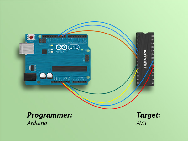
Learn how to use Arduino as ISP to burn bootloader on AVR microcontrollers. Arduino as ISP to burn bootloader on AVR micros with code example
I've loaded ArduinoISP onto the Uno using the Arduino IDE, but now I'd just like to make sure what pins to use for the 6 ISP slots on my mouse
The guide shows this

But nothing for RESET
And then I'd like to just use avrdude to dump/flash the chip, but it's all about flashing bootloader using Arduino IDE
I think I have the right program on the UNO and the right wiring, but when trying to read the flash on the target chip I get this:
❯ avrdude -c avrisp -p m32u2 -U flash:r:g600firmware -v

avrdude: Version 7.0
         Copyright (c) Brian Dean, http://www.bdmicro.com/
         Copyright (c) Joerg Wunsch

         System wide configuration file is "/etc/avrdude.conf"
         User configuration file is "/home/vermoot/.avrduderc"
         User configuration file does not exist or is not a regular file, skipping

         Using Port                    : /dev/ttyS0
         Using Programmer              : avrisp
avrdude: stk500_recv(): programmer is not responding
avrdude: stk500_getsync() attempt 1 of 10: not in sync: resp=0x00
^C
i am trying to find an example that is not just burning the bootloader
another writeup: https://docs.arduino.cc/built-in-examples/arduino-isp/ArduinoISP
merry cave
Ah that's awesome, thank you I'll have a look at that
Hmm
Seems my wiring is correct, and I do have ArduinoISP loaded onto the uno correctly
But in your first link the solution to OP's problem was using this command : avrdude -p m328p -P /dev/ttyACM0 -c avrisp -b 19200 -U flash:w:release.hex
And the only difference between that and mine is specifying the port and baudrate, which had no effect on mine
livid osprey
merry cave
But in your first link the solution to OP's problem was using this command : `av...
Try replacing m328p with m32u2?
Ah, wait, that was the example.
Can you verify the Arduino is connected to /dev/ttyS0?
merry cave
livid osprey
Can you verify the Arduino is connected to `/dev/ttyS0`?
I believe it's connected to /dev/ttyUSB0
Though when I try -P /dev/ttyUSB0 I get this
avrdude: Device signature = 0x1e950f (probably m328p)
avrdude: Expected signature for ATmega32U2 is 1E 95 8A
         Double check chip, or use -F to override this check.

avrdude done.  Thank you.
So I guess that's trying to read the Uno itself, and not the 32u2 through the uno
I've also tried-P /dev/ACM0 which results in the same as above (stk500 etc)
stable forge
i think that you want the 328p as the chip because that's what the uno is, and it's doing a passthrough??
stable forge
avrdude: Device signature = 0x1e950f (probably m328p)
merry cave
Yeah, to me that means that my command targets the wrong port and tries to read the m328p on the UNO, but since I specified -p m32u2 it's giving me this error
stable forge
what does ls /dev/tty* show as connected? You can unplug it and plug it in and compare
that will tell you the port.
stable forge
yah, so if you do this avrdude -p m328p -P /dev/ttyUSB0 -c avrisp -b 19200 -U flash:w:release.hex
what happens
merry cave
But if I understand the process right, I'm not targeting the uno, I'm targeting my m32u2, using the uno as the programmer
stable forge
what sketch is running on the Uno? You loaded some ISP-quelque-chose sketch on it
some pass-through sketch
merry cave
stable forge
what sketch is running on the Uno? You loaded some ISP-quelque-chose sketch on i...
I did yeah, ArduinoISP from the Arduino IDE examples
stable forge
but I think it may still see the Uno as a 328p
merry cave
Is it actually supposed to be passthrough like that though?
Like, I read the uno and I get what's on the m32u2?
stable forge
that's the idea, but maybe the ID part cannot be overriden by the passthrough program. I don't know
merry cave
huh
stable forge
For instance, the example from stackexchange (https://electronics.stackexchange.com/a/205060/101049) specifies m328p even though it's programming at attiny
merry cave
Hmmm alright
stable forge
go ahead and try it, it shouldn't mess up the Uno
livid osprey
Not sure if still relevant, but probably worth looking at: https://forum.arduino.cc/t/what-avrdude-arguments-do-i-need-to-use-the-arduinoisp-programmer/514563
Arduino Forum
Edit: solved. The standard installation of Avrdude doesn't have arduinoisp or arduinoisporg in the avrdude.conf file. Find that file, open it in a text editor, find the programmers section, and add this: programmer id = "arduinoisp"; desc = "Arduino ISP Programmer"; type = "usbtiny"; connection_type = usb; usbvid = 0x2341; ...
merry cave
stable forge
go ahead and try it, it shouldn't mess up the Uno
I'm more afraid about messing up the m32u2, I need to back up what's on it before anything else 😄
livid osprey
Seems avrdude doesn't come with an Arduino ISP configuration by default.
stable forge
oh no
merry cave
So then avrdude -c avrisp -p m328p -P /dev/ttyUSB0 -U flash:r:g600firmware -v -b 19200 should get me the mouse's current firmware into the specified file right?
merry cave
livid osprey
Seems avrdude doesn't come with an Arduino ISP configuration by default.
All of the guides I've seen mention using avrisp for an Arduino as ISP setup
stable forge
I installed avrdude with sudo apt install avrdude, and it knows about avrisp. I did avrdude -c notreal and it listed all the ones it knows
including avrisp
merry cave
yep
livid osprey
Oh, I always thought AVRISP and ArduinoISP were two different things...
Hm.
Yeah, the Arduino IDE has them as two separate items. I thought AVRISP was an Atmel-made device...
stable forge
so the advice in the link about will still be helpful
merry cave
Yeah I'm lost now
OOH
avrdude -c avrisp -p m328p -P /dev/ttyUSB0 -U flash:r:g600firmware -v
that worked, and I've got a file now
Now, how do I know if it's the uno's firmware or actually the G600's firmware 😄
The file is 31.9K
stable forge
merry cave
Now, how do I know if it's the uno's firmware or actually the G600's firmware 😄
do strings on it and you might see interesting stuff
merry cave
Failed to read from DHT sensor!
Humidity:
Temperature:
 *C
 *F
Heat index:
So, definitely the Uno's firmware
stable forge
so you compiled and uploaded the ArduinoISP sketch? I would not expect to see DHT stuff in there
merry cave
I'm pretty sure I did
livid osprey
That does not look like the firmware I'd expect from either device haha
merry cave
(There was also a line saying AVR ISP)
Here's the file I got
Anyway I don't think the passthrough thing worked 😄
stable forge
try to load blink on the board, and see if it works, and then try ArduinoISP again. I don't see any strings in the ArduinoISP sketch. Maybe add a string definition and see whether it shows up in the dump.
merry cave
I'm terrified of overwriting the mouse 😄
stable forge
well, how about disconnecting the mouse and trying the avrdude read again, and see if it works or not
merry cave
Yeah, I disconnected the mouse, loaded blink with a custom string, ran the avrdude command again and yeah, the file I got is indeed the new thing I just loaded
stable forge
also maybe trying the arduinoisp additions to the avrdude config files
yeah, but blink overwrote the passthrough. So load the passthrough sketch again, and then try avrdude again (without mouse connected)
merry cave
stable forge
yeah, but blink overwrote the passthrough. So load the passthrough sketch again,...
Yeah, the result of that is the same as the file I got before
stable forge
i give up for now, got to do other stuff, sorry! we know it's possible, something wrong
merry cave
No worries! I'm off for a bit as well
merry cave
Alright, this guide is pretty relevant to my situation
and :
If your AVR is different then change the option -p m328p to -p ... corresponding to your microcontroller. Most likely you do not have to modifythe other options.
So yeah, I do need to use -p m32u2
 elfin thorn
Hi y'all! I'm running an Adafuit Clue with the Sensor Plotter sketch. How can I display a Greek character in there? Thanks!
merry cave

I've just been told "this is not an uno, it's got a ch340 instead of 16u2 doing serial comms, that may be an issue"
@stable forge @livid osprey thoughts??
merry cave
There also seems to be a whole thing about using a 10uF capacitor between reset and GND that people mention in places, but I'm not sure if it applies to my case (and I don't have any)
north stream
merry cave
I've just been told "this is not an uno, it's got a ch340 instead of 16u2 doing ...
I doubt that's the issue: obviously you have a setup that can talk to the CH340.
merry cave
Cool
north stream
merry cave
There also seems to be a whole thing about using a 10uF capacitor between reset ...
I think the capacitor is between the pin used for the reset signal in the serial comms chip (generally DTR or RTS) and the reset pin on the target MCU: it's used as sort of a differentiator to turn a level into a pulse. However, I don't know if it's needed with arduinoISP, as you could presumably have the Arduino controlling the process generate the pulse directly with an I/O pin (but I don't know that much about arduinoISP, so I don't know if it works that way or not).
livid osprey
Are you still having trouble with this mouse?
merry cave
Yep!
As of now I still haven't been able to communicate with it through the UNO as ISP
merry cave
north stream
I doubt that's the issue: obviously you have a setup that can talk to the CH340...
Are we sure of that though? I can definitely talk to the UNO's m328p and write to it, but that's about it for now
livid osprey
Oh, I believe arduino is a valid programmer option for avrdude. Maybe try that instead of avrisp?
merry cave
Same thing:
avrdude: stk500_recv(): programmer is not responding
avrdude: stk500_getsync() attempt 1 of 10: not in sync: resp=0x00
^C
Hm. Is your UNO loaded with the programmer sketch?
merry cave
I believe so, yes. I've successfully uploaded the ArduinoISP sketch with the IDE
livid osprey
I remember yesterday your firmware might have had some DHT-related stuff in there, which shouldn't exist in the ArduinoISP sketch.
north stream
Note that the programmer sketch has some optional stuff (like USE_OLD_STYLE_WIRING and configuring which pin to use for reset) that may need to be customized for your setup
merry cave
livid osprey
I remember yesterday your firmware might have had some DHT-related stuff in ther...
I've tried the same with additional string definitions to make sure it was on there properly, and it was
merry cave
north stream
Note that the programmer sketch has some optional stuff (like `USE_OLD_STYLE_WIR...
Yes, I did uncomment that as well
livid osprey
I don't think we're that far in yet, the errors suggest the UNO isn't responding to avrdude's requests.
Maybe try reloading it? I do this from time to time, just to make sure...
merry cave
I've done so multiple times already 😅
merry cave
Yep
Here's the sketch I'm loading onto the UNO
Which is just the standard "Examples > ArduinoISP" sketch, with line 81 (USE_OLD_STYLE_WIRING) uncommented
I succesfully load that onto the UNO (I see blinking lights when loading it, and the IDE says success)
The hardware setup is the same as pictured above (I think all of the jumpers are in the right places)
livid osprey
Oh. Can you try again, but this time put some sideways pressure on the mouse-side of the jumper wires as you press the button?
I see they're not soldered, so intermittent contact may be a major issue.
merry cave
I can, but I'm pretty sure they're making solid contact: they're all pressing against each other and their slots, and last time I did a continuity check between the UNO's pins and the mouse's actual chip, everything was contacting just right
Yeah, no, it's the same
Yep, checked again between the UNO's pins and the mouses chip: everything is in contact with what they need
north stream
It looks like the arduino programmer for avrdude supplies the reset pulses on both DTR and RTS, so it should work with most any serial adapter. Basically, I think it uses reset to start the sketch and get its attention then sends packets via the serial link and listens for a reply. That's those stk500 sync messages. If it doesn't get the right reply, either the sketch isn't running, it failed to reset the board, there's a configuration mismatch (such as asynch speed, some run at 56k, some at 115k), there's a wiring problem, or there's a hardware problem.
merry cave
Ok
Hardware problem, I don't think so: the mouse still runs fine when plugged into my computer
Wiring problem, aside from something on the PCB between the ISP pins and the chip that I don't know about, I don't think so either; my setup (with the UNO and the jumpers) seems fine.
But since I've ran successful continuity tests between the UNO's pins and the chip's pins, I don't think so?
Configuration mismatch is very plausible, but at this point I don't know what my options are, then
Maybe I should just try and get my hands on a capacitor and try the setup people are talking about
north stream
I'd check that the reset pin configured in arduinoISP corresponds with the one you have hooked up. I'd also try using the serial monitor to see what (if anything) comes back from arduinoISP when it's manually reset.
There are basically six ISP pins: power, ground, reset, clock, MOSI, MISO
north stream
Note that it differs whether you're using "old style wiring" or not
merry cave
Correct
north stream
It sounds like you're really close and have eliminated most of the possible issues
merry cave
Yes
Which doesn't feel great, since at some point if it's still not working I'll have no idea what to do anymore 😄
I didn't expect this part of my project to be this difficult
merry cave
From someone on the QMK server:
I have used china clone Arduinos as isp flashers and that stupid ch340 chip is definitely not a problem. What is an actual problem is exactly that 10uF capacitor. You absolutely need the capacitor when flashing through ISP Arduino for reset to work correctly but it doesn't have to be 10uF, it can be bigger. I used 100uF that I salvaged from god knows where when flashing 16u2 to different bootloader
And I managed to find one
merry cave
Right then, now with the capacitor on the Uno I have new results...
❯ avrdude -c avrisp -p m32u2 -P /dev/ttyUSB0 -b 19200 -U flash:r:g600firmware

avrdude: AVR device initialized and ready to accept instructions

Reading | ################################################## | 100% 0.02s

avrdude: Device signature = 0x000000 (retrying)

Reading | ################################################## | 100% 0.02s

avrdude: Device signature = 0x000000 (retrying)

Reading | ################################################## | 100% 0.02s

avrdude: Device signature = 0x000000
avrdude: Yikes!  Invalid device signature.
         Double check connections and try again, or use -F to override
         this check.


avrdude done.  Thank you.
it's entirely possible the SPIEN fuse has been turned off, which means you'd need to get the chip off the board and into a parallel programmer to read anything from it
I'm being told
 sacred ivy
General question: Do ya'll put comments on every if statement to tell what they are supposed to do? Just in case you ever need to go back and figure out what a program does? Or do you assume you'll be able to read it and figure it out in a year?
livid osprey
For me personally, I'm pretty terrible with commenting, so I usually only comment high-level functions unless I have very complex logic that's hard to read. For simple if statements, generally I just try to use variables and predefined constants that are easier to read.
pine bramble
sacred ivy
General question: Do ya'll put comments on every if statement to tell what they ...
Only if it's not my usual way of doing things or go against every best practices but still has to be done
otherwise the variables used by the if and decomposition into methods should be self-explanatory
ie //despite what the datasheet says, the PWM for this sensor need to be a 302Hz rather than 400Hz
sacred ivy
Yea, little "gotchas"
so you dont pull your hair out a year down the line when you use the same code 🙂
pine bramble
Also this is a border case and both sides has merits, but if my switch take more than one screen I'd rather split what each does into different methods
Because my brain capacity is 1 page of code for best use of it
sacred ivy
🤡 Yea i havent figured out a good system for when Im using say, main.c and then another c page for tmr0.c.
"This file does this and controls the timer but also Im toggling an LED" 🤡
 lucid minnow
Would it be faster for a raspberry pi to send a message to an arduino based microcontroller using a single pin or using SPI? RPi outputs HIGH on the pin, and MCU (constantly polls OR uses a RISING edge interrupt) and reads the HIGH and runs the conditional code. Would this be faster than SPI? There isn't really an 8 bit message I want to send. I think I should know this. Like in SPI you have to change the ChipSelect pin (so that's the time it would take for one pin write) and then the time required for sending the 8 pulses for the clock and the data line. The button should be faster right?
pine bramble
you do know the rpi is not real-time right ? And might take about 1-15ms to send a message (not guaranteed)
lucid minnow
pine bramble
you do know the rpi is not real-time right ? And might take about 1-15ms to send...
Considering the unknown timing though, which method is still relatively faster 😅 I should know this but I'm so exhausted right now
What about the MCU end? Reacting to a pin interrupt would be faster than SPI read, right?
pine bramble
Problem with a button is that while you are pressing it it may register tons of times at the microscopic level (ie: debouncing). I'd think protocol that require the least overhead might be ideal
but again the arduino is real-time and might have done 15 million thing between the time the rpi get the input to send the message and the time it sends it
so you may want to consider if that is ok for your use because at arduino scale, 15ms is a LONG time
lucid minnow
Nobody is "pressing" a button. The RPI is raising is high or low. Even on SPI, it would just send a boolean message i.e. SPIwrite ("im feeling high"), or SPIwrite("im feeling low")
pseudo stone
@sacred ivy one of the better things I've read about commenting is you should focus on saying why things are the way they are instead of what they are. Whats take about a second to realize from reading code most of the time whereas why a decision was made is something that will almost always be forgotten
Excluding constants if you have some weird constant it needs explaining
Or math in general also should be explained
pine bramble
I'd even explain non-weird constants
you might understand it now, but might not in 6 months
pseudo stone
With python in particular typehints go a long way to making better code as well
pine bramble
even if it's pi. Yeah it's pi, but nobody know the unlimited numbers after the dot, or if even they are unlimited or not. So if you are using not using 3.1416f you might want to explain why you need more precision or less
livid osprey
lucid minnow
Would it be faster for a raspberry pi to send a message to an arduino based micr...
As far as interrupts go, they're usually handled on a separate line to keep the actual ISR itself short and offload the read functionality outside. The response to an interrupt would be fastest, but the communication would usually be handled after.
Single pin communication and SPI have pretty much the same speed for most applications, as they're both functionally similar when it comes to unidirectional data. The advantage to SPI is usually bidirectional data, a synchronous clock for stability and slightly higher speed cap, and a hardware interface on the lower level to handle all the SPI logic. If you were to use software SPI, there could be delays associated with all the extra overhead, but otherwise there shouldn't be a difference.
If you're only trying to communicate a single boolean, I'd definitely use an interrupt-enabled GPIO over SPI. SPI really only makes sense for serial communication, which isn't required to send a single change in a boolean state.
 thorny osprey
I got a Adafruit Feather question: I'm using a propmaker, and I'd like the code to use bluetooth speakers (needing central mode) and control what audio is played through those speakers through the Adafruit App(needing peripheral mode). According to the second question here https://learn.adafruit.com/adafruit-feather-m0-bluefruit-le/faq Adafruit Feather nRF52 Bluefruit LE can do both, but can it both both at once, where I press a button on the phone app, it'll play through the speakers?
I'd like to do a mode where the microcontroller does its own sounds through the speaker, but also a "puppet" mode dictated by the app. Can the Adafruit Feather nRF52 Bluefruit LE do that?

Adafruit Learning System
Twice the Cortex M0 for a powerful BLE portable
stable forge
thorny osprey
I got a Adafruit Feather question: I'm using a propmaker, and I'd like the code ...
I'm not sure if you're asking about sending audio over Bluetooth or not. The answer is that we don't support BLE audio. It's quite new.
CircuitPython has Apple Media control stuff: https://github.com/adafruit/Adafruit_CircuitPython_BLE_Apple_Media, but that is for pause,play, etc on the phone
thorny osprey
stable forge
I'm not sure if you're asking about sending audio over Bluetooth or not. The ans...
Aah, yes, i'm asking for the microcontroller/feather to send audio over bluetooth to a bluetooth speaker
and that the Adafruit phone app can tell the microcontroller to play something over the bluetooth speakers
can a feather that can do classic bluetooth be able to do this?
 river kindle
I have a question about the SSD1306 library. I wanted to use software i2c so I can have multiple displays running. I see the constructor for specifying the mosi and sclk pins, but what are the dc and cs pins? My module only has SDA and SCL lines so I'm not sure what to specify for them in the constructor.
Nevermind. I read the description wrong. I thought it could do software i2c, but it's software SPI.
 brazen falcon
You could use something like a TCA9548A to run multiple i2c displays that are hardwired to the same address
pine bramble
Heyyyy
I wanna learn arduino
How n where to start
brazen falcon
Could start with https://learn.adafruit.com/series/learn-arduino
river kindle
brazen falcon
You could use something like a TCA9548A to run multiple i2c displays that are ha...
That looks like the perfect solution! The other libraries that support multiple screens that I've found don't support using a different font like the adafruit library, so they won't work for my project. Ordered up a breakout board from adafruit to give it a try.
brazen falcon
There's also the LTC4316 which can transparently translate a device to a new address.
livid osprey
river kindle
Nevermind. I read the description wrong. I thought it could do software i2c, but...
Have a look at https://www.arduino.cc/reference/en/libraries/softwire/ maybe?
The Arduino programming language Reference, organized into Functions, Variable and Constant, and Structure keywords.
stable forge
thorny osprey
Aah, yes, i'm asking for the microcontroller/feather to send audio over bluetoot...
ESP32 can do classic Bluetooth, but we don't have experience with that. https://www.google.com/search?q=arduino+esp32+classic+bluetooth will get you some leads
 low verge
Hi. Can someone tell me why VS code always tell me that it doesn’t found the include file in browse.path ? Even when I configured them and files compile without any problems. It annoys me
thorny osprey
stable forge
ESP32 can do classic Bluetooth, but we don't have experience with that. <https:/...
aaah, sounds like classic bluetooth is the way to go then! thanks for the info!
 native dagger
Does a long strip or array of neopixels update faster in arduino than CP for the same MCU?
cedar mountain
native dagger
Does a long strip or array of neopixels update faster in arduino than CP for the...
The actual show() update would generally be the same, since it's mostly limited by the bit rate for the data sent to the Neopixels. But the code to calculate the animation colors in memory ahead of time would run at different speeds, with Python generally being slower.
native dagger
Hmm ok
Thanks that's what I was thinking as well
What if the colors were being read from a file?
Or a list or array?
cedar mountain
There are certainly things you can do to optimize, and depending on the scenario it might not matter (since all you have to do is be able to update the colors in memory faster than they can be pushed out to the pixels, to get "full" frame rate).
There are also ways to hook up multiple strips in parallel to update everything faster.
But of course I often quote Knuth: "Premature optimization is the root of all evil." The first step is to figure out whether it's actually a bottleneck for you at all.
pine bramble
Can you select a active servo with push button so I can control 2 servos independently with 1 potentiometer?
livid osprey
pine bramble
Can you select a active servo with push button so I can control 2 servos indepen...
Certainly, if everything goes through your microcontroller
pine bramble
Yeah I have a arduino uno
Currently I am able to control 1 servo with 1 potentiometer but I have no idea where to start to be able to toggle between 2 servos
livid osprey
If you have two servo objects, you just need a variable to determine which object your potentiometer controls and a means to change the variable with your button.
native dagger
cedar mountain
There are certainly things you can do to optimize, and depending on the scenario...
any links or stuff I can search regarding parallel?
cedar mountain
native dagger
any links or stuff I can search regarding parallel?

GitHub
The FastLED library for colored LED animation on Arduino. Please direct questions/requests for help to the FastLED Reddit community: http://fastled.io/r We'd like to use github "...
native dagger
cedar mountain
https://github.com/FastLED/FastLED/wiki/Parallel-Output
Nice! I'd looked at Octo and was like "Hm 8 pins seems somewhat arbitrary"
north stream
The 8 comes from the transfer size of the DMA engine, I think
north stream
I suspect the choices were 8, 16, or 32 and 8 seemed a reasonable one.
 tawny mural
what ide do most people here use or is arduino-cli + editor/ide of choice the way to go? arduino ide is horrible…
 inland gorge
tawny mural
what ide do most people here use or is arduino-cli + editor/ide of choice the wa...
inland gorge
tawny mural
what ide do most people here use or is arduino-cli + editor/ide of choice the wa...
I generally use the Arduino IDE for compiling / uploading and set its "use external editor" preference. Then I use a standard text editor to actually edit the code: Atom, emacs, vim, etc.
tawny mural
yeah that’s what i’m probably gonna end up doing, thanks @inland gorge
 solemn cliff
I used to use arduino-cli, but I don't use it often and I believe there's a catch where you have to install libraries and board definitions differently with arduino-cli sometimes ? and then there's remembering what the command line options are... so I moved to doing like Todbot
inland gorge
tawny mural
yeah that’s what i’m probably gonna end up doing, thanks <@352910176736772096>
Some people like the PlatformIO integration with Atom or VS Code, but I've found it difficult to match PlatformIO Arduino library & board versions to official releases.
inland gorge
solemn cliff
I used to use arduino-cli, but I don't use it often and I believe there's a catc...
oh yeah for big Arduino projects with lots of compiles I use arduino-cli sometimes too. It's what the IDE uses underneath, from what I gather
lapis monolith
cedar mountain
But of course I often quote Knuth: "Premature optimization is the root of all ev...
Ah, so Knuth didn't change his first name to "Don" and go hide in the desert after all! Good to hear his wisdom still being invoked.
tawny mural
thanks @inland gorge i think i’ll bite the bullet and get acquainted with arduino-cli at some point in the future, for now, emacs+arduino-mode and copy paste into the abomination that is arduino IDE
solemn cliff
don't copy paste, just edit the file with your own editor
tawny mural
well to compile it i’ll copy it from my editor into arduino ide?
solemn cliff
nope, you have "mysketch/mysketch.ino", you open that in the Arduino IDE, and you open it in your editor
you need this setting for the Arduino IDE to read the changes from the external editor

then when you press "compile" and "upload" it does it with whatever changes you made in your other editor
tawny mural
right, wouldn’t i still be able to write the code in my other editor, paste it into arduino ide and then compile it though?
solemn cliff
hmmm you can not paste in "external editor" mode, the idea being that you don't want to edit it from 2 places I assume
but why not just save ? copy-pasting just feels like an additional step to me
I guess to each their workflow !
tawny mural
i will end up getting familiar with arduino-cli and removing arduino ide entirely, it’s really bad imho..
solemn cliff
the hard part for me was figuring out the parameters that match the Tools menu selections
 neat pond
lapis monolith
Ah, so Knuth didn't change his first name to "Don" and go hide in the desert aft...
neat pond
lapis monolith
Ah, so Knuth didn't change his first name to "Don" and go hide in the desert aft...
wow. haven't heard Knuth quoted for a long time .. I may have to dig out one of my copies & look them over. kids nowdays just turn a glazed eye at you when you mention him (yes, i am a retired Programmer/Systems Analyst 😋 ) ..
cedar mountain
neat pond
wow. haven't heard Knuth quoted for a long time .. I may have to dig out one of ...
That does raise an interesting question... is there a comparable guru for the current generation of programmers that I should be paying more attention to?
restive smelt
Hi I'm following the AHRS fusion tutorial on the adafruit website. I Can't figure out what is wrong with my COM readout. This is what my calibration look like after iIwrite then read.

The sensor I'm using:Adafruit LSM6DSOX + LIS3MDL - Precision 9 DoF IMU - STEMMA QT / Qwiic
The board I'm using:Assembled Feather HUZZAH w/ ESP8266 WiFi With Stacking Headers
With a 100 mm cable between the board and sensor
and a Adafruit FeatherWing OLED - 128x64 OLED Add-on For Feather (STEMMA QT /
Qwiic)
The AHRS tutorial: https://learn.adafruit.com/how-to-fuse-motion-sensor-data-into-ahrs-orientation-euler-quaternions

Adafruit Learning System
A basic IMU (Intertial Measurement Unit) generally provides raw sensor data, whereas an AHRS takes this data one step further, converting it into heading or direction in degrees.
 brave roost
Hi, apologies if this is posted in the wrong spot.
I've got me one of those cheap high voltage transformers off of amazon & I want to pulse it @ 10hz for 20ns per pulse
So my questions are:
- Am I going right about this involving a teensy at all? maybe there is a smarter approach to this? My thinking to use it is cause I have it and its fast.
- How might I drive the transformer indirectly while maintaining the rapid response time needed, solid state relay according to my googling works at 1ms delay which would be too slow for the nano second pulses.
north stream
brave roost
Hi, apologies if this is posted in the wrong spot.
I've got me one of those chea...
A) the transformer circuitry probably won't respond anywhere near that fast. B) The Teensy probably can't make a pulse that narrow. C) You'd need a switching transistor and enough circuitry to make it switch that fast. I used to have a job building high voltage high speed pulsers (my fastest one had a 350ps risetime to 2kV), it's harder that it sounds.
brave roost
dang, welp I guess here goes a deep dive into electronics to figure this out
thanks for the input
though another problem in even attempting to make that is lack of high end equipment to verify any speeds
sacred ivy
Question about if statements:
if ((BatteryDone==1)|| (Raw_IFB<=25)&&(Voltage_mode==1))
Would this evaluate how Ive written it? So if BatteryDone=1 OR Raw_IFB less than 25 AND Voltage_mode=1, then do what ever is in the if statement?
I want either condition to evaluate to the next step, so if the Battery is done, do the next thing or if the analog value coming in (Raw_IFB) is less than 25 and its in voltage mode, I also want it to do the next thing
logically, this is what I think it should evaluate to
 north stream
brave roost
though another problem in even attempting to make that is lack of high end equip...
north stream
brave roost
though another problem in even attempting to make that is lack of high end equip...
The gold standard is the Tektronix P6015A high voltage probe, but even that expensive thing only goes to 75MHz (at 20kV). So you'd need an impedance matched system and voltage divider to even check it. I had access to fancy things like that in my job, but I don't work there any more, so I'm using an older (and more affordable) P6013A (12kV, 25MHz).
north stream
sacred ivy
Question about if statements:
`if ((BatteryDone==1)|| (Raw_IFB<=25)&&(Voltage_mo...
I would strongly suggest putting parenthesis around the && part to make it obvious to both the coder and the compiler what the desired behavior is.
if ((BatteryDone==1) || ((Raw_IFB<=25) && (Voltage_mode==1)))
sacred ivy
north stream
I would strongly suggest putting parenthesis around the && part to make it obvio...
thanks 🙂
the nice thing about c is that its universal for the most part 🙂
elfin thorn
Hi y'all! I'm running a sound reactive sketch on the Circuit Playground Classic. It works beautifully, but the original sketch has the rainbow colors. I changed it enough to where I get all blue - but I want all white. I've been changing parameters but nothing seems to get me the white LEDs. Can anyone help? Thanks!
leaden walrus
looks like it should be white
are you seeing a change in color when you change line 149?
else leds[i] = (255, 255, 255); //constrained to yellow color, change CHSV values for rainbow
No... solid blue. Weird, eh?
leaden walrus
are you sure its in sound reactive mode?
elfin thorn
Positive... been testing that all day yesterday and this morning.
Do you think it could be the neopixels themselves?
leaden walrus
could try a simple sketch to just fill them with a color
elfin thorn
I plan on connecting external Neopixels this coming week, but won't have time today.
True... I'll give that a shot. This just seems very strange indeed.
leaden walrus
it does. it's probably something else. the fact that the code change is doing nothing seems odd.
elfin thorn
But, as far as the code, it looks correct, yes? I'm not missing anything.
leaden walrus
yep. nothing obviously wrong with the code.
elfin thorn
Alrighty then... Once I connect the external LEDs, I'll see if it gives me a different result. Thanks so much for your help!
leaden walrus
can try now using the onboard neopixels
elfin thorn
Sure... got to leave here in about 10 minutes though.
Changed to this:
lse leds[i] = (255, 0, 0); but still blue pixels
I think I found it.
I changed the following:
    else leds[i] = (255, 255, 255); ```

But now the LED light up white by default (instead of being off) and when it reacts to sound, turns blue.ohhhh. yep.
elfin thorn
I'll have to do this later... got to go with my wife ... I appreciate your help though!
leaden walrus
else leds[i].setRGB(255, 255, 255);
Trying that now.
Wifey is getting impatient. 😁
BEAUTIFUL!!!!!!!
That worked perfect.... THANK YOU!
leaden walrus
cool. sry. not super familiar with fastLED. didn't see that with a quick scan.
you'll need to make same change here:
if (peak > 0 && peak <= NUM_LEDS-1) leds[peak] = (255, 255, 255);
I'll give that a shot when I get home, but your above change looked perfect.
pine bramble
When someone is impatient after leds that can turn on/turn off 10000 times a second...
 noble oxide
hey all. has anybody had any luck integrating neopixels into the RP2040 Nano Connect WIFI LED example sketch or something similar?
noble oxide
pine bramble
When someone is impatient after leds that can turn on/turn off 10000 times a sec...
Laughed. 😉
 vague kettle
heya! hit a roadblock on my project, hoping for a nudge in the right direction. hope this is the right room. project includes an arduino driving a stepper + servo, need to get some data from the internet using either a pi or esp32, and hopefully control it from my iphone using bluetooth or wifi...
goal is to point at mars, or the space station, etc etc... my "robot" + arduino is working great, now i need to get data to it. ill have the pi or esp32 contact JPL Horizon system using http put + get requests, that interface seems easy enuf... my problem is getting the thing on the internet. i want it to be portable, so i want to either have an app on my phone grab the data, then send it to the esp32/pi... or open up a hotspot on my phone, and have the esp32 grab the data thru that.
making an iphone app seems to be a decent roadblock. ive toyed with MIT App Inventor, and it seems capable, but it seems to require that im at my pc
north stream
Using a Pi, you could send serial data to the Arduino. My usual approach for projects like this is to use something like a Feather or ItsyBitsy with an AirLift board to add WiFi functionality. There is this AirLift board available for use with an Arduino: https://learn.adafruit.com/adafruit-airlift-breakout/arduino

Adafruit Learning System
Give your project an airlift with this WiFi-BLE breakout!
vague kettle
ive talked from pi to arduino over serial before, ive considered that. i could use that to connect to a hotspot on my phone to grab the data. then i could write a webapp for control and serve that up on the pi
total noob at webapps tho. any good recommendations on a starting point?
north stream
That seems workable to me
vague kettle
im new to the esp32 and kinda want to toy with that, but may be too much trouble for this lil project
north stream
The AirLift boards work by having firmware (called "Nina") that has the ESP chip act as an SPI peripheral and you send it commands to do the WiFi communication for you. So it's not super useful for learning about ESP programming in particular, but you do have to learn how to use the AirLift library to talk to it. Since you've already done the learning on communicating with the Pi, that may make more sense for this case.
vague kettle
ty much!
tawny mural
I’m a bit of a beginner with all this embedded/arduino stuff so this might be sort of a dumb question but if i have a sensor on the i2c bus at address 0x77 i can have another sensor using the i2c bus with a different address right?
native dagger
Yup!
tawny mural
with the same pins, SDA/SCL?
native dagger
Yup!
tawny mural
Ok thank you!
native dagger
That's the strength of I2C
tawny mural
fantastic, something else must be the issue then, this soil sensor doesn’t initialize properly
north stream
tawny mural
fantastic, something else must be the issue then, this soil sensor doesn’t initi...
You can run an I2C scanner to see if it's answering up at the expected address
tawny mural
i’ll check that next, got a bit sidetracked wiring up some http requests
restive smelt
Hi I'm trying to follow This tutorial on calibrating a Adafruit LSM6DSOX + LIS3MDL - Precision 9 DoF IMU. I setup Jupyter notebook in Visual Studio Code and I can get the first block to run. I get the Error in the photo when I attempt to run the second block of code. I can't figure out what is wrong. The code remains unchanged aside from the COM port https://learn.adafruit.com/adafruit-sensorlab-gyroscope-calibration/gyro-calibration-with-jupyter Thankyou for the help


Adafruit Learning System
Keep your spinner steady with some basic calibration
pine bramble
I'm trying to burn a bootloaded to an atmega 2560 the problem is that I get "avrdude: Yikes! Invalid device signature.
Double check connections and try again, or use -F to override
this check.
Error while burning bootloader.
" ; then I'm trying to run it without checking the signatures, by running avrdude from cmd, but it's not recognized, even though it is installed
no idea about how to use -F on arduino
north stream
pine bramble
I'm trying to burn a bootloaded to an atmega 2560 the problem is that I get "avr...
Look at the signature bytes it reports. If it's all zeros or all ones (like 0xff ff ff), you have a communication problem. If it's a reasonable looking but different signature (like 58 42 6e instead of 47 21 b1), then it's set up for the wrong CPU type, version, or variant.
pine bramble
north stream
Look at the signature bytes it reports. If it's all zeros or all ones (like 0xf...
in the end I've somewhat solved by using another board to flash the bootloader in the other board
but right now idk, I can load some basic sketch on it, but it won't load heavier stuff, and it's not a memory issue...
north stream
What are the signatures it reports?
pine bramble
solved again thanks
low verge
Hi I want to generate 3 PWM signals for brushless motor control with half bridge drivers. I stuck to how to generate 3 PWM for that. I don’t really know how to control the 3 PWM independently
Anyone can help me?
livid osprey
low verge
Hi I want to generate 3 PWM signals for brushless motor control with half bridge...
Ah, is this 3 PWM for 3 phases of a brushless motor?
livid osprey
What kind of BLDC? How many poles?
low verge
e-bike motor
12 poles
With hall sensor (which I don’t know how to use)
Sorry for bad english. My official language is french
livid osprey
Oh, so a 3-phase BLDC, with half-bridge drivers...
low verge
Yes exactly
livid osprey
low verge
I will use 3 IR2104 along with 6 N-channels Mosfets
livid osprey
Oh, yeah, exactly that. Have a look through that link and see if that code does what you want?
 woeful knot
hello, I dont know how to resolve an error for #include lib
#include errors detected. Please update your includePath.

Im using platformio
lapis monolith
woeful knot
Did you install the Adafruit_SSD1306 library in your Arduino development environment?
 untold ravine
Hi, I have a circuit playground bluefruit and would like to view the sensor data wirelessly onto the bluefruit connect app or on pc. How should I do this without connecting the USB to the pc and read it on the arduino serial monitor?
sacred ivy
I dont use arduino a lot so Im trying to port code over to another processor. In this video he shows his code
https://www.youtube.com/watch?v=k9hibCPbQ08&list=PLGOjlGENB8gXVvR9ke2SgF0XTT1dBWmhv&index=18
8:38. First he defines a char and sets it to null, thats fine
char character ="";
But the next part, I dont understand
String data_from_display="";
Whats the difference between the two? Does "String" convert values? Im trying to find the equivalent function for my microcontroller
I think what 'String' does is make an array of characters. So if I were to do this:
char data_from_display[16]
and
String data_from_display="";
I think they would be the same
north stream
untold ravine
Hi, I have a circuit playground bluefruit and would like to view the sensor data...
That depends on what connection options your PC has. You might be able to use Bluetooth or an asynchronous serial link, or possibly something else.
north stream
sacred ivy
*I* think what 'String' does is make an array of characters. So if I were to do...
There is a difference. If I want a null character, I'll usually specify it explicitly like '\0'. Your line char data_from_display[16] is technically incorrect, as an array of characters is a char * not a char. A String is a whole 'nother thing, that's the C++ abstraction of a string, which contains an array of characters, a length, along with a bunch of methods to do various things like comparing, appending, or modifying the array. The C array (the first one) is compact and efficient, but you have to do everything manually (if you want to compare, you use a function like strcmp(), if you want to add more characters than will fit, you have to reallocate the memory). With the C++ String class, you can compare strings with == and append text and it will reallocate it for you. The penalty is it takes a lot more memory and CPU cycles to operate.
 ionic scaffold
Do you know of a good way to control a 2.4 GHz radio receiver with a feather? I'm trying to control studio lighting with Home assistant
livid osprey
ionic scaffold
Do you know of a good way to control a 2.4 GHz radio receiver with a feather? I...
2.4GHz? Is this Bluetooth, Wifi, or something else entirely?
ionic scaffold
Yeah I'm kinda confused too
Lemme send the products

Buy Genaray Endeavor ML-33K Daylight LED Monolight featuring Extremely High Output: 33,000 lux @ 3 ft, 5600K Color, Measures 16.8 x 9.8 x 7", CRI/TLCI: 97.5/98.5, Dimming: 0 to 100%, Integrated 16-Channel Receiver, Beam Spread: 120 Degrees, Wireless Control w/ Optional Transmitter, Thermostatically Controlled Fan Cooling, Tungsten Conversion Fil...
Trying to control something like this
Their system is this:

Genaray Light Seeker Remote
I wonder if there's a spec sheet out there
I found the user manual and they still just say 2.4 GHz radio signal
They probably don't really want people making their own controllers lol
livid osprey
Something else entirely, huh. Well, it's not impossible to reverse engineer a dedicated system like this, but usually it's not worth the cost. People have used specialized sniffers to scan the transmitted frequencies and record data to decode, but it's not an affordable or trivial task...
ionic scaffold
Yeah haha. I'll have to look for a more friendly one ig
I think it'd be a fun project but probably not worth the time rn
livid osprey
The frequency bands here probably aren't even all that complex, usually it's just 2400MHz +/- some channel modifier, usually in 1MHz intervals. The transmission protocol, on the other hand...
ionic scaffold
yeah that makes sense
I'm no expert on Radio either so it'd be a challenge for sure haha
north stream
Most of those things are FSK or a fairly simple spread spectrum protocol. There's a fairly small number of popular chips in use.
livid osprey
^^ more of an expert than I am, anyhow.
north stream
I'm in the process of building my own 2.4GHz remote control gear, which necessitated learning a good bit about how the existing ones work. A couple of months ago, it was all a mystery to me too.
 crystal yacht
You can integrate home assistant with Adafruitio online. https://learn.adafruit.com/integrating-adafruit-io-with-home-assistant/esphome-setup

Adafruit Learning System
Home Assistant tracks the state of all the devices in your home, so you don't have to, and Adafruit IO can store it all!
Will require an esp32 feather which can emulate some smart home devices if I’m not mistaken. To control lights you’ll need a 110/220v relay.
If you don’t mind running circuit python jon park has a learn guide controlling studio lights with a LORA solution.

A Feather board without ambition is a Feather board without FeatherWings! This is the Power Relay FeatherWing. It gives you power to control, and control over power. Put simply, you can now ...
lapis monolith
crystal yacht
Will require an esp32 feather which can emulate some smart home devices if I’m n...
Is there a way to get devices we make/program control existing wifi/Google Home/Alexa devices?
crystal yacht
Without using Adafruit io? Yes but you’ll need to add esp32 or WiFi capability to your existing device, specifically because the esp32 can emulate a smart device.
lapis monolith
Unrelated question, I'm trying to get some example Arduino code to run on a QTPY M0. Part of my confusion is that the device (SSD1331) has I2C pins that you connect, but everything I see only talks SPI to it. The other thing is, where do I find the list of #defines for the QTPY pins, so I can understand the pin substitutions I'll be making?
crystal yacht
If your asking if an esp32 can trigger other smart devices through your smart home hub I don’t know, beyond my experience. You should search the internet for that answer.
I’m horrible with spi and i2c, someone else would need to jump in.
lapis monolith
crystal yacht
If your asking if an esp32 can trigger other smart devices through your smart ho...
I already have. It seems Google at least is eager for you to make client devices but not things that can give their devices or other client devices commands.
lapis monolith
crystal yacht
I’m horrible with spi and i2c, someone else would need to jump in.
I just need to understand, if I've got code that says #define dc 6, which of the numbers on the pinout does that match, and when I see:
``#include <Adafruit_NeoPixel.h>
// create a pixel strand with 1 pixel on PIN_NEOPIXEL
Adafruit_NeoPixel pixels(1, PIN_NEOPIXEL);``
where are PIN_NEOPIXEL and the things like it defined?
crystal yacht
C:\Users\Username\AppData\Local\Arduino#\packages\adafruit\hardware\YOURBOARDMODEL\version\variants\YOURBOARDVARIATION\variant.cpp worth looking into if you’re on windows
livid osprey
lapis monolith
Unrelated question, I'm trying to get some example Arduino code to run on a QTPY...
According to the datasheet, the SSD1331 does not have an I2C interface. The pins you're referencing are likely labeled in a way that might suggest otherwise, but the serial interface is not a two-wire equivalent. Reference: https://cdn-shop.adafruit.com/datasheets/SSD1331_1.2.pdf
As for the QTPy M0 pin definitions, https://github.com/adafruit/Adafruit-QT-Py-PCB/blob/master/Adafruit QT Py SAMD21 pinout.pdf, or try looking for a pins_arduino.h file in C:\Program Files (x86)\Arduino\hardware\arduino\samd\variants\<your board here>? Path may vary, I don't actually have any SAMD boards installed on my work PC...
lapis monolith
pins_arduino.h in the same place as variant.cpp (C:\Users\username\AppData\Local\Arduino15\packages\adafruit\hardware\samd\1.7.10\variants\qtpy_m0) looks to have the pin #defines I was looking for, thanks.
 gilded swift
Hello, so I am working on porting a logic analyzer Arduino sketch for an ESP8266 to an ESP32-S2 and i am running into some issues. Not compiler wise, just not getting any values from the GPIO_IN_REG which I believe is the same as the GPI implementation in esp8266_peri.h.
I set up my pins:
static const int PIN0 = 4;
static const int PIN1 = 5;
static const int PIN2 = 6;
static const int PIN3 = 7;

static_assert(PIN0 >= 0 && PIN0 < 53, "");
static_assert(PIN1 >= 0 && PIN1 < 53, "");
static_assert(PIN2 >= 0 && PIN2 < 53, "");
static_assert(PIN3 >= 0 && PIN3 < 53, "");
static constexpr uint32_t MASK = (1 << PIN0) | (1 << PIN1) | (1 << PIN2) | (1 << PIN3);

void setup() {
  Serial.begin(baudrate);

  pinMode(PIN0, INPUT_PULLUP);
  pinMode(PIN1, INPUT_PULLUP);
  pinMode(PIN2, INPUT_PULLUP);
  pinMode(PIN3, INPUT_PULLUP);
}```setup my extern method for collecting values from the GPIO_IN_REG:
unsigned long times[N_SAMPLES]; // when did change happen
uint32_t values[N_SAMPLES];     // GPIO_IN_REG value at time

extern void ICACHE_RAM_ATTR collect() {
  times[0] = micros();
  values[0] = GPIO_IN_REG & MASK;
  for (int i = 1; i < N_SAMPLES; ++i) {
    uint32_t value;
    do {
      value = GPIO_IN_REG & MASK;

    } while (value == values[i - 1]);
    times[i] = micros();
    values[i] = value;
  }
}```the esp8266 version has value compaction so I kept that. not sure if I need it with the RAM that the ESP32-S2 has:
int compactValue(uint32_t value) {
  int res = 0;
  if ((value & (1 << PIN0)) != 0) {
    res |= (1 << 0);
  }
  if ((value & (1 << PIN1)) != 0) {
    res |= (1 << 1);
  }
  if ((value & (1 << PIN2)) != 0) {
    res |= (1 << 2);
  }
  if ((value & (1 << PIN3)) != 0) {
    res |= (1 << 3);
  }
  return res;
}```ah wait, I think I found what I may have missed 😛
sacred ivy
north stream
There is a difference. If I want a null character, I'll usually specify it expl...
So I have a bit of a basic question about this: Why are are chars in this instance followed by a pointer? so char*
Is that just a rule of "c"?
cedar mountain
In C, arrays and pointers are generally equivalent, as they are both a variable that points to the first element but can be modified to access subsequent elements too. And C-style strings are arrays of chars, so they're often referenced as a char*.
sacred ivy
Thanks 🙂 Programming isnt my strong suite especially with C.
cedar mountain
Don't worry about it. A lot of people have trouble with C pointers. It's a major stumbling block in learning the language.
sacred ivy
What Im trying to do is eventually get to use these nextion type LCDs with a project I have in mind. They communicate via UART, and thus send out stuff in ASCII. But, Im doing things step by step first. What I fail to do is take notes. I did this once before with a PIC24F 😬 but apparently forgot how it works
I actually went back to old code but I have no clue how the original authors would have come up with it. It does read the UART properly, which is nice.
`void EUSART_Read_Text(char *Output, unsigned int length)
{
unsigned int j;
for(j=0;j<length;j++){
Output[j] = UART1_Read();
}
}
Some ways down:
void main(void)
{ char buf[16];
unsigned int val;
memset(buf,0,16); //set things to 0's
while (1)
{

    EUSART_Read_Text(buf,3); read only 3 bytes of UART
    val = atoi(buf); //convert ascii to integer numbers
}
`
north stream
Heh, mine would have been even more mysterious: ```c
static void
EUSART_Read_Text(
char * Output,
unsigned int length)
{
char * endp;
for (endp = Output + length; Output < endp; ++Output) {
*Output = UART1_Read();
}
}
Once I really understood pointers, I began to have an unhealthy fondness for them.
cedar mountain
Ummm... what? Those are all identical, AFAIK. (Response to now-deleted comment.)
gilded swift
You would think so.. but in C (not C++) I’ve had issues using one vs the other.
cedar mountain
I'd be highly interested in an example, though of course I understand if that's not feasible or too much hassle.
gilded swift
Geeks for geeks has a C lang shell example, I implemented it but ended up having to change where the * was because of compiler errors
It could have easily been a freak very corner case example
I delete my comments as to not cause confusion from things that have happened to me but could have easily been just random errors that shouldn’t have happened
sacred ivy
So what tells the complier if what Im declaring as a variable is a number or a string? Case in point the above example I posted. Im not doing any string manipulation yet, therefore, everything is treated as 8 bit binary numbers, right?
 tardy iron
which particular variable in your example?
sacred ivy
buf
tardy iron
you declared it as char []
sacred ivy
But is it an ascii value or just a regular 8 bit representation?
tardy iron
that's up to you. as far as the compiler is concerned, char is a 8-bit number. whether it's signed or unsigned depends on the compiler (signed for most Arduino platforms, i think?)
cedar mountain
In other words, an ASCII value is exactly just a number... 'A' == 65.
sacred ivy
Gotcha
sacred ivy
If I understand the arduino map() function correctly, as long as I dont have minimums, I can reduce the equation to the following:
assuming mins are just 0. X is our var in and y is output
y=x*(outmax/inmax)
since the result is fractional, using Ints it would be different. If my Max in (x) was 100, and my output was 255 then I would get:
y = (x*255)/100
So if the user wanted to put in 0 to 100%, this scales correctly.
The only big issue is the x*255 product. If x is a big number, you might overflow. I dont think its a problem for unsigned ints though.
cedar mountain
Yep, you've got that right. As you noted, there can be some subtleties with integer overflow or with dividing first instead of multiplying first. Sometimes people will purposefully cast a value to a larger integer type to be safer.
ionic scaffold
I am trying to make a feather esp32 v2 into a peripheral, but I can't get it to respond to my I2C write signals from another board
I'm getting this for the signal being sent, no ack bit and the color of the neo pixel is supposed to be changing after the feather gets the signal but it doesn't, so it's like not responding to the signal at all

 night crest
Hi. I have a Clue that I'm trying to get working with a sketch. I thought I installed all the libraries, but it keeps giving me this error. Attached is the sketch. Thank you.
Arduino: 1.8.19 (Windows 10), Board: "Adafruit CLUE, S140 6.1.1, Level 0 (Release), Serial"
WARNING: library Adafruit_WavePlayer_Library claims to run on samd architecture(s) and may be incompatible with your current board which runs on nrf52 architecture(s).
tricorder:608:20: error: variable or field 'scan_callback' declared void
608 | void scan_callback(ble_gap_evt_adv_report_t* report)
| ^~~~~~~~~~~~~~~~~~~~~~~~
tricorder:608:20: error: 'ble_gap_evt_adv_report_t' was not declared in this scope
tricorder:608:46: error: 'report' was not declared in this scope
608 | void scan_callback(ble_gap_evt_adv_report_t* report)
| ^~~~~~
tricorder:681:26: error: variable or field 'bleuart_rx_callback' declared void
 frigid ridge
so i am trying to work with a sketch that was originally intended for an adafruit feather nRK52840 Sense. it's like no one sells it or has it. micro center near me has an arduino nano 33 ble which as far as i know is fairly similar. i know a few of the pins would need to be adjusted but otherwise it seems like almost a 1 for 1. the code i am working with was meant for the feather. i have all the libraries installed, but get this error:
'PIN_SERIAL1_RX' was not declared in this scope
//buttons, scroller    - d2 pin supposed to be pin #2
//button on the board is connected to pin 7.  TX is pin 0, RX is pin 1 - these are normally used for serial communication

#define BUTTON_1_PIN                PIN_SERIAL1_RX
#define BUTTON_2_PIN PIN_SERIAL1_TX ```that is the line i was told to change, but looking at the pin out pictures the buttons would be on the same labeled pins.
livid osprey
frigid ridge
that is the line i was told to change, but looking at the pin out pictures the b...
PIN_SERIAL1_TX/RX should have the one removed, as the Nano 33 BLE defines them as PIN_SERIAL_TX/RX.
frigid ridge
livid osprey
`PIN_SERIAL1_TX/RX` should have the one removed, as the Nano 33 BLE defines them...
thanks. probably going to have more questions, but the short of it right now is are the boards interchange able for the most part? am i way in over my head? (possibly).
livid osprey
They use the same nrf52840 module, so there should be a way. Without knowing the exact sketch you're trying to convert, I can't speak for how easy the switch is, but the number of pins are comparable so it's highly likely you're on the right track?
frigid ridge
well diagram wise i feel like i am on the right track. i cant stand the light mode that Arduino has because it is difficult to read.
livid osprey
frigid ridge
well diagram wise i feel like i am on the right track. i cant stand the light mo...
Even if they don't make it obvious, open-source applications are pretty easy to modify to your liking haha
frigid ridge
oh my god that is so much better
im used to just adjusting the marlin code for my 3d printers so a lot of it is just changing values. i was hoping the same for this honestly lol. it seems like that may be the case, but i just am not sure what values i should be hunting and changing them to since it isnt as straight forward as i hoped.
this is the original diagram he has for the pin out

here is the notes i made for what am hoping to use. the only thing i didnt add was the power switch because the most i can think to put that on would be where the 3v and the ground would be


GitHub
WIP list of assets that will be used with arduino tricorder - ArduinoTricorder/tricorder_sense.ino at master · lambtor/ArduinoTricorder
that is the git hub for what he made.
so far it seems like the only things i have to change are what the pins are, but some of them just to me seems like a 1 to 1. the hang ups i get are on lines 41 to 51. at least for now.
sacred ivy
ionic scaffold
I'm getting this for the signal being sent, no ack bit and the color of the neo ...
Just a basic trouble shooting question but are your I2C lines pulled up?
livid osprey
frigid ridge
here is the notes i made for what am hoping to use. the only thing i didnt add w...
Yeah, the Nano BLE doesn't expose the enable pin. If you're handy with a soldering iron and comfortable with PCB rework, you might be able to solder something to IC1:17 to turn the 3.3V bus on/off.
frigid ridge
That won't be a problem.
livid osprey
Don't try to turn the board off by shorting 3v3 to ground. That sounds like a bad idea.

 open palm
Hello, I am looking for a way to call one of my 3 integer functions by random
I have these 3 functions defined, but i want to call on 1 of the 3, but have it randomly selected which one is called on.

 rough torrent
There's a random function provided by the Arduino framework
 livid osprey
int randNumber = random(3); //random integer selected from [0, 1, 2]
switch (randNumber) {
  case 1:
    //do something when var equals 1
    halfBuzzer();
    break;
  case 2:
    //do something when var equals 2
    quarterBuzzer();
    break;
  default:
    // if nothing else matches, do the default
    wholeBuzzer();
    // default is optional
    break;
}
There are no other variables. I took the functions you defined in your first screenshot.
Though, on that note, your functions never actually return an integer, which would probably throw an error.
open palm
ohh sorry im slow, If i did do what I was asking it would only be picked randomly each startup not each time it ran.
Thanks so much for your help
ionic scaffold
sacred ivy
Just a basic trouble shooting question but are your I2C lines pulled up?
they should be by the wemos i am using as the controller. I made a forum post now: https://forums.adafruit.com/viewtopic.php?f=57&t=191893
the scope seems to imply it's pulled up i believe
 chilly vigil
Is it possible to use the rfm69 via i2c instead of spi?
livid osprey
chilly vigil
Is it possible to use the rfm69 via i2c instead of spi?
Not without a controller device in between, no.
chilly vigil
Ok thanks
 mortal grove
hello! I'm interested in recreating this solenoid setup (https://www.adafruit.com/product/2776) but controlling two solenoids at the same time with one Trinket, I assume I need two transistors and two diodes, is that the case? also, I'm not quite sure which ones to get, is it these transistors https://www.adafruit.com/product/976 and these diodes https://www.adafruit.com/product/755 ? thanks!
Solenoids are basically electromagnets: they are made of a coil of copper wire with an armature (a slug of metal) in the middle. When the coil is energized, the slug is pulled into the ...

Transistors are powerful little electronic switches, and when our little NPN transistors aren't power enough for your project, we have been known to use these beefy TIP120 Darlington ...

This here is a 10 pack of the classic 1N4001 power blocking diode. These are good for reverse polarity protection (put it between your DC power jack and circuitry to avoid a negative-voltage ...
pine bramble
mortal grove
hello! I'm interested in recreating this solenoid setup (https://www.adafruit.co...
Honestly the big issue is the power supply
Can't power it from the USB, will need to be 7-8V (exact model of the trinket please?)
mortal grove
pine bramble
Can't power it from the USB, will need to be 7-8V (exact model of the trinket pl...
I have a 5V Trinket, but I'm happy to get a different Arduino if there's a better way to go
pine bramble
the diode also as a voltage drop, so I'd go more for 8V
Power conversion isn't a topic I understand a lot but the job of the transistor is to up the 150mA into 1.1A
since the base current is 120mA you won't be able to power two (but there might be some tricks that others know)
the transistor can supposedly go up to 120A apparently 😄
I mean your solenoid will draw what it need, but you have some margin here ...
pine bramble
mortal grove
I have a 5V Trinket, but I'm happy to get a different Arduino if there's a bette...
Just to make it clear, the part I don't like is that imho this has to be provided with 8V but the teensy will regulate it down to 5V afaik
which suggest you'd power the solenoid directly (with says 9V@1A power supply) but then you wouldn't need the transistor
also the diode isn't Schottky diode which limit the options available
pine bramble
mortal grove
I have a 5V Trinket, but I'm happy to get a different Arduino if there's a bette...
I'd suggest you wait for a reply from someone more experience than me, if you can't please check https://core-electronics.com.au/guides/solenoid-control-with-arduino/ to at least connect the diode so nothing get broken

Core Electronics
In this tutorial, we will look at the basics of Solenoids and how they work. Then we will design a small circuit that can drive a Solenoid from the input/output pins on your Arduino board.
We covered a whole bunch of rotational motion concepts when we looked at DC motors and how they are used with Arduino. It’s only fair to give linear motion t...
native dagger
mortal grove
hello! I'm interested in recreating this solenoid setup (https://www.adafruit.co...
Yes those would work well.
There are other options but there's nothing wrong with those, especially if you are comfortable with them
As for a power supply, are you planning on just doing prototyping on a breadboard?
native dagger
mortal grove
I have a 5V Trinket, but I'm happy to get a different Arduino if there's a bette...
This depends on what your goals are besides the solenoids.
mortal grove
native dagger
This depends on what your goals are besides the solenoids.
thanks. the goal is an art piece that would have both solenoids fire very rapidly together for about 15 seconds, then wait till the next person triggers them. so it needs to be semi robust, as it will be a closed and final art piece that needs to reliably and consistently work on its own, but it doesn't need to be over-engineered as it is still a fun personal project
native dagger
Ok!
Well you're in luck with the trinket 5V
You can put enough voltage on the BAT pin to power your solenoids and it will also power the trinket so you can do one power supply
Only possible wrinkle is what happens when you plug in the USB cable but adafruit are smart and probably dealt with that. Ping me tomorrow and I'll look at the schematic. I'm working on an art piece too!
I think protoboard is going to be a good choice for your final project
mortal grove
native dagger
Only possible wrinkle is what happens when you plug in the USB cable but adafrui...
I was checking the trinket product page for info on this and saw a deprecation warning for something around how the usb works. I am not super space constrained, so looking around it appears the "upgrade option" is the ItsyBitsy (https://www.adafruit.com/product/3677)
We recommend this as an upgrade from the Pro Trinket 5V because this has native USB so it will work with all computers, USB serial debugging, and a more reliable bootloader.

What's smaller than a Feather but larger than a Trinket? It's an ItsyBitsy! Small, powerful, Arduino-compatible - this microcontroller board is perfect when you want something very ...
mortal grove
native dagger
You can put enough voltage on the BAT pin to power your solenoids and it will al...
And it looks like the ItsyBitsy has a BAT pin as well! So my guess is I can do the same thing and power two solenoids. Do you know of any reason that wouldn't be the case?
lapis monolith
That is probably the "same architecture" closest upgrade. If you don't have any code that depends on the processor specifically, there's also a Trinket M0. I believe all of Adafruit's M0 and M4 have native USB, though I don't work for them and might be wrong about that.
north stream
mortal grove
And it looks like the ItsyBitsy has a BAT pin as well! So my guess is I can do t...
Yes, that should work well. The M0 option is nice too (different hardware and 3V instead of 5V), but should also be possible to control two solenoids and offers more RAM and flash.
rough torrent
The M4 also allows you to use CircuitPython, which can be more user-friendly
Much more RAM (192K instead of 32K I believe)
And...other stats I don't remember lol
pine bramble
Yeah I just remembered how unwieldy and not like standard C++ arduino can be...
  if (int(timeElapse / 1000) == 1 && (timeElapse % 1000) == 0)
  {
    MESSAGE1();
    return;
}Is there a better way to do this ?
rough torrent
Not sure but I don't think you need (timeElapse % 1000) == 0 as that will be true when int(timeElapse / 1000) == 1 is true
Also, I believe people would typically not use the int function and use casting, which essentially does the same thing: (but don't quote me on it - I've also only experienced C++ with Arduino lol)
int(timeElapse / 1000) == 1 -> (int)(timeElapse / 1000) == 1
pine bramble
well modulo is 1R1 when millis = 1001ms and I want to do this when it's at 1000ms
so that I react on 1R0 instead of 1R1
The left part is / the remainder is %. Right ?
I assume that milis is a float here but could be wrong
rough torrent
millis returns an unsigned long
rough torrent
pine bramble
The left part is / the remainder is %. Right ?
Yes
pine bramble
Ah since it's a long I'll just check for 1000, 4000, 7000 etc then
rough torrent
pine bramble
well modulo is 1R1 when millis = 1001ms and I want to do this when it's at 1000m...
Also, depending on how fast your Arduino is, it might not be fast enough to check exactly at the 1000ms mark.
Like for example it might check at 999ms and next check is at 1001ms
And it would never get called
pine bramble
yeah... thta is probably why I have some issues with later messages
especially since lcd.print and lcd.clear isn't instant
rough torrent
You might want to do something like this?
unsigned long timeElapse = millis();  // NOTE THE USE OF UNSIGNED LONG
if (timeElapse > 7000) {

} else if (timeElapse > 4000) {

} else if (timeElapse > 1000) {

}  // etc
I'll just upload the ino since that is probably going to be easier or hastebin it somewhere
rough torrent
wait backwards fixed
pine bramble
I guess I'll go with the elseif in that case. Don't want to spend too much time on it it's just an LCD test program
to test my 5 LCDs after soldering the female headers on them
rough torrent
Could you just do this? ik delay isn't the best idea as it's obviously blocking but you don't seem to need to do anything else while waiting between the messages
MESSAGE1();
delay(3000);
MESSAGE2();
delay(3000);
// etc...
MESSAGE9();
delay(16000);  // this number was eye balled
while (true) {
  lcd.clear();
  lcd.setCursor(2, 0);
  // lcd.print(String(millis() / 1000) + " seconds");  // using the String lib isn't suggested in a loop
  // try this
  lcd.print(millis() / 1000);
  lcd.print(" seconds");
  // may want to delay so that you can actually read it
  delay(100);
}
edit: fixed syntax error
edit2: update comment on not using string lib
pine bramble
Yeah I can. The messages don't loop but from 40s I still have to protect the LCD so I'd turn off the display for 10 seconds then turn it back on every 10 seconds after 40s
thanks!
rough torrent
I'm trying to get an I2S mic (https://www.adafruit.com/product/3421) working with my Adafruit PyGamer but it doesn't want to compile:
Arduino: 1.8.19 (Windows 10), Board: "Adafruit PyGamer M4 Express (SAMD51), Enabled, 120 MHz (standard), Small (-Os) (standard), 50 MHz (standard), Arduino, Off"

<truncated>

Using board 'adafruit_pygamer_m4' from platform in folder: C:\Users\ckyiu\AppData\Local\Arduino15\packages\adafruit\hardware\samd\1.7.10

Using core 'arduino' from platform in folder: C:\Users\ckyiu\AppData\Local\Arduino15\packages\adafruit\hardware\samd\1.7.10

Detecting libraries used...

<truncated>

Alternatives for I2S.h: [I2S@1.0]

ResolveLibrary(I2S.h)

  -> candidates: [I2S@1.0]

<truncated>

Error while detecting libraries included by C:\Users\ckyiu\AppData\Local\Temp\arduino_build_971788\sketch\InputSerialPlotter.ino.cpp

<truncated>

Error while detecting libraries included by C:\Users\ckyiu\AppData\Local\Arduino15\packages\adafruit\hardware\samd\1.7.10\libraries\I2S\src\I2S.cpp

<truncated>

Generating function prototypes...

<truncated>

In file included from C:\Users\ckyiu\AppData\Local\Arduino15\packages\adafruit\hardware\samd\1.7.10\libraries\I2S\examples\InputSerialPlotter\InputSerialPlotter.ino:20:

C:\Users\ckyiu\AppData\Local\Arduino15\packages\adafruit\hardware\samd\1.7.10\libraries\I2S\src/I2S.h:111:2: error: #error "I2S is not supported on your board!"

  111 | #error "I2S is not supported on your board!"

      |  ^~~~~

Using library I2S at version 1.0 in folder: C:\Users\ckyiu\AppData\Local\Arduino15\packages\adafruit\hardware\samd\1.7.10\libraries\I2S

exit status 1

Error compiling for board Adafruit PyGamer M4 Express (SAMD51).
The PyGamer is a SAMD51 so I believe it has I2S support.

Listen to this good news - we now have a breakout board for a super tiny I2S MEMS microphone. Just like 'classic' electret microphones, MEMS mics can detect sound and convert it to ...
It compiles happy for the Feather M0 board but not for the Feather M4 express:
I've posted the full Arduino logs (they are huge lol) to this forum post: https://forums.adafruit.com/viewtopic.php?f=25&t=191934&p=928543
 marble ice
Hey everyone so I got a PCB with a RP2040 and everything is working fine but it's limited to 125hz polling rate so 8ms of response time . My device is for rythm game so I really need to have it to 1000hz 1ms . Do anyone know how I can do that ? Thank You
cedar mountain
marble ice
Hey everyone so I got a PCB with a RP2040 and everything is working fine but it'...
You'll need to provide some more information. Polling what, using what software?
marble ice
Polling rate (input delay) , my board is just a 2 key keypad using a RP2040 , some one made me a firmware on Arduino using Adafruit and keyboard.h to run it and everything is working perfectly but my device is stuck to 125hz of polling rate so 8ms of delay . Most gaming keyboard are 1000hz polling rate so 1ms . Because my device is for rythm game I really need to make it run at 1000hz polling rate but the guy who made me the firmware doesn't know how to make it run at 1000hz . I've asked a lot of people but nobody seem to know .
pine bramble
is using a firmware like gp2040 an option ?
and how do you know it's 125hz and 8ms of delay?
marble ice
I tried but my board is completely different it's really a simple 2 key keypad so it doesn't work with the gp2040
I tested it with multiple software and website it's pretty hard to really calculate the polling rate of a keyboard but every time it calculated the polling rate of my keyboard correctly and every time my board was calculated at 125hz
pine bramble
so it's the polling rate of the USB, not the SPI right ?
marble ice
I really don't know I think but I'm really a amateur in the technical field
pine bramble
by keyboard is that a normal usb keyboard (like with qwerty etc?)
I'm asking these to clarify what is being polled exactly that you expect at 1khz
and if that is dependent on the rp2040 or not
marble ice
it's an USB C the PCB is really just a small keyboard PCB
it's like a regular keyboard just it only has 2 key instead
pine bramble
a Basic Polling is basically just asking for a reading 1 time per ms 1000 times and really easy to code... that's why it need clarifying
do you know the model of the keyboard pcb / can you take a pic ?
pine bramble
I don't know how to read PCB anyway, but that assumes that the PCB support 1khz polling. I know that cheap keyboards don't... so even if you actually set up the code to do it it might not support it
ie: slow polling and not being able to press 2-3 keys at once is an hallmark of a cheap keyboard
ok might have found something
marble ice
Nah the PCB is working extremely well I'm using it for rythm game so it's really going hard on it with spamming the key at 250 bpm and it's acting better than most of the keyboard i had . I think it's only firmware issue
pine bramble
is your PCB connected to USB_DM or USB_DP pin for the USB?
marble ice
I really don't know is that something I can check on the PCB schematic ?
pine bramble
oh it has the rp2040 on it ?
marble ice
Keyboard.h
pine bramble
can you list all the .h ? It might be easier to figure out how the PCB wants us to do it assuming it's plugged on the full-speed usb pin
if it's not it doesn't seem possible to do 1khz
marble ice
#include <Adafruit_NeoPixel.h>
#include "Keyboard.h"
that's the only h the PCB is using
pine bramble
can you open keyboard.h to know which library it is exactly ?
should say near the top in the comments
marble ice
yea i'm just trying to install everything back . Because I changed computer 2 sec
pine bramble
would be better to just upload keyboard.h unless this is top secret or something
and seems I dont have a cable for my qt py 😢
so sick of this USB cable war
marble ice
how do I upload it (again I'm very sorry I'm really not into technical thing)
pine bramble
plus to the left of a message that you type in discord
marble ice
I feel so dumb I don't understand a thing , I can go in the library manager in Arduino but I don't understand what you want exactly i'm sorry
When I go in the Library and click on the Keyboard is just give me this #include <Keyboard.h>
#include <KeyboardLayout.h>
#include <Keyboard_da_DK.h>
#include <Keyboard_de_DE.h>
#include <Keyboard_es_ES.h>
#include <Keyboard_fr_FR.h>
#include <Keyboard_it_IT.h>
#include <Keyboard_sv_SE.h>
don't know if this what you asked for sorry
pine bramble
the file should be in your documents/arduino/name_of_your_project folder
marble ice
Okay yea I understand
pine bramble
when you include a library in the arduino ide library manager it put a copy in your project folder
that library would have to support changing the polling
marble ice
Okay and do you know a library that support that ?
pine bramble
you can't just use any library, it has to be compatible with the PCB
marble ice
Okay and is there a way I could find a library that work with my PCB and support the polling rate change ?
pine bramble
it would have to be coded, and since you have pushbuttons a high polling rate isn't really useful
they are basically switch and react almost instantly besides the debouncing
and the library you are using is arduino keyboard library
tardy iron
switch bounce on mechanical keyboard switches is on the order of 5ms, so 1kHz (1ms) polling is going to take some work to do reliably, no matter the platform
pine bramble
could try to recode it with tinyusb but since they are pushbuttons I don't think that will be useful
pine bramble
tardy iron
switch bounce on mechanical keyboard switches is on the order of 5ms, so 1kHz (1...
it's not a mechanical keyboard, it's just 2 pushbuttons on a pcb
tardy iron
it's the actual physical switch that has those properties. what kind of pushbuttons are they?
pine bramble

that is the pic of the custom pcb that rocco sent me @tardy iron
5ms imply that this is being correctly debounced (and quickly) which would be a good assumption on a mechanical keyboard from a good brand. But here? Not sure what assumptions would hold
marble ice
Is there any test I can do to know how "good" my PCB is ?
pine bramble
@tardy iron even in arduino's keyboard.cpp HIDSubDescriptor doesn't seem to accept a polling rate
marble ice
Also I found that Library but it doesn't seem to have any mention of polling rate change https://github.com/jpconstantineau/BlueMicro_HID_Arduino_Library#bluemicro_hidsetusbpollinterval2

GitHub
Universal BLE/USB HID Library. Contribute to jpconstantineau/BlueMicro_HID_Arduino_Library development by creating an account on GitHub.
pine bramble
I assume the pushed keys are put in a buffer somehow but I can't see any polling rate in the library
@marble ice tusb.h (tinyusb) support a polling rate but the hardware still has to support it
and if you have another library that mean redo the code
you can't just change keyboard.h to something else
marble ice
Is there a way I can check if my hardware support 1000hz
tardy iron
if you have enough keys (full-sized keyboard) to need a row-column key matrix, you typically have to scan row-column pairs, and that slows things down. with only two buttons, you can just read the port pin values as fast as you want, but you still have to do debouncing
pine bramble
marble ice
Is there a way I can check if my hardware support 1000hz
you'd need to have the pcb files
but I can't really help with that
marble ice
I have everything
pine bramble
so more skilled peoples than me can check if the debouncing is done correctly on the PCB and if it's actually connnected to the full speed pin of the rp2040 on the PCB instead of the low speed one
pine bramble
tardy iron
if you have enough keys (full-sized keyboard) to need a row-column key matrix, y...
That is my verdict, would probably need custom code for this
can't just slap a gp2040 on this or some generic usb HID code
marble ice
If some one know how to create a code like that I'm ok to pay
I really just want this to work at 1000hz
pine bramble
they would need the pcb files that were used to print it too
this is way out of my league personally
I tried because the topic interested me and I could run into a similar issue but I'd have the rp2040 directly and access to all the pins so not the same scenario at all
marble ice
Maybe I can ask the guy who designed the PCB if he connected it to the full speed pin
pine bramble
one would see it from the pcb files possibly
there would be a square that says USB_DM or USB_DP with a line connected to it
marble ice
Honestly I'm like desperate because even the guy who made the PCB and did the code couldn't find a solution but the GP2040 support 1000hz so there gotta be a solution somehow
pine bramble
but the gp2040 is directly using the rp2040 and the pins
which the PCB encased, so not the same thing
do you understand that they sort of removed features from the rp2040 by doing that?
And do you understand what debouncing is ?
marble ice
Nah as I said I'm really out of my league to I'm not even on the same planet I have almost 0 knowledge in that
I'm already happy to have a device that I working very well , but I'm so close to the perfect device
pine bramble
you may actually be very far, so far that it would require changes to the PCB
marble ice
Yea i know that suck
pine bramble
It may seem to you that it's close but that isn't necessarily the case
but I get the feeling, everytime I open a broken electronic I bought at say walmart and I feel like I could reuse some of the components or repair it
but they do everything they can so I can't
marble ice
I have other pcb design with the atmega32 it probably would have been a lot easier but they are out of stock and over priced that's why I ask to change the design and went with the rp2040 but there is so much less support
pine bramble
atmega328p?
marble ice
u4
pine bramble
I see, the one on leonardo
marble ice
If there is some one who maybe able to fix my issue I would pay honestly i'm too deep in my project to back off now
pine bramble
the rp2040 is perfectly capable of doing that but I don't know how much the PCB jailed it
If I had the rp2040 on a board with access to all pins and tinyUSB library it would be pretty simple for me
I'd just connect it to the correct USB pin (full-speed) and use tinyUSB with a single line to put it in 1000hz mode
but I don't know what your PCB did, and that's the gist of the issue
I've come here to ask for help with rp2040 too (but with circuitpython) so we're almost in the same boat :p
marble ice
if only there was some kind of test I could do on the PCB to test it. The only thing I know is that it's working very well on my game
pine bramble
Also trying to find you a keyboard rate tester
Just foujnd out my mouse is only 125hz with such an utlity so going to throw it in the trash 🤣
That explains a lot
that's over 60Hz so...
marble ice
Honestly I don't even think it's that important for me it feel really good to play with but I'm not insane at the game so I can't test the limit of my device
pine bramble
My reaction time is above 70ms anyway personally
so 1khz would be useless for me
I can't click that fast
marble ice
Nobody can lmao
 pine bramble
so 125hz is more than sufficient for me


 pine bramble
ok 😦
pine bramble
guess I'm a boomer 🤣
marble ice
I can't believe it's that hard to lower that number
pine bramble
that's the library you are using: https://www.arduino.cc/reference/en/language/functions/usb/keyboard/
The Arduino programming language Reference, organized into Functions, Variable and Constant, and Structure keywords.
nothing in there to improve the polling rate
marble ice
Again if anyone know how to fix my issue I would gladly pay for a new code
pine bramble
Or else it wouldn't be that hard
marble ice
yea i know i read everything
pine bramble
which mean you need new code, possibly using something like tinyusb
marble ice
You can change polling rate on tiny usb ?
pine bramble
yeah, that is what gp2040 which uses it does
marble ice
oh yea I think it's that TinyUSB_Port_InitDevice() hardware specific (clock, phy) to enable usb hardware then call tud_init(). This API is called as part of TinyUSB_Device_Init() invocation.
pine bramble
But I'm not sure we have the same understanding of polling rate
You seem to think that it's a feature that come with rp2040 or your PCB
and that you just have to enable it
marble ice
Nah I don't know honestly
pine bramble
Polling rate is just how many time a second that the code will try to read the value
marble ice
At first I thought that but know I understand it depend on the way my PCB is designed
pine bramble
It's a code thing
But the hardware has to support it too, ie: the leonardo only refresh values 500 times a second
so it can't do 1000hz no matter how hard you try
marble ice
Yea but the issue now is that I can't find some one to tell me if my PCB is capable of doing it
pine bramble
and the debouncing of the button (ie: filtering when the metal of the switch touch the wire at a microscopic level) also need to take less than 1ms
So there's no question that a library like tinyUSB can do it if the hardware can refresh the signal fast enough
when you say you have pcb files do you mean eagle ?
marble ice
Just need to find some one than can check if my PCB is capable of doing it and then write the correct code
pine bramble
and/or do you have schematic in a jpg/png etc picture ?
marble ice
I have the gerber file , pick and place file , bom , schematic
but it's custom made so I probably can ask the guy any kind of file regarding the pcb and he would be able to give me everything
pine bramble
what format is the schematic ?
marble ice
pine bramble
can you upload it in the channel ?
pine bramble
To everyone benefit

yeah but I meant the channel 😄 not me in the DM.
seems like the USB would be capable of high speed
marble ice
Honestly that's my bad I should have asked the guy before to make it for 1000hz
pine bramble
I guess SW1 and SW2 are the buttons but not sure
pine bramble
at first glance there doesn't seem to be hardware limitations
marble ice
nice
pine bramble
Just would need to change the code for the debouncing in arduino to make sure it can do it in less than an ms
and integrate tinyusb with it
pine bramble
I don't have an rp2040 or I would have tried to help more obviously
marble ice
if you know anyone
pine bramble
since this is relevant to my interest and I'll have to implement a much faster debouncing solution for 24 buttons and 12 switches eventually myself
I'd post your request at https://jobs.adafruit.com/
Find maker jobs in 3D and CAD, Art, Design, Education, Embedded Development, Engineering, Fabrication, Marketing and Communications, and Web Development
this is typically the answer when someone seek to pay someone for work in the discord
marble ice
Oh nice
pine bramble
since it's a custom pcb make sure to include the files you have for it and the arduino code so someone can evaluate how long it would take them
and so that you get what you actually need
pine bramble
rough torrent
I've posted the full Arduino logs (they are huge lol) to this forum post: https:...
bad news at first glance https://github.com/adafruit/ArduinoCore-samd/issues/86
seems the support for i2s on samd51 isn't good
in that particular library
pine bramble
rough torrent
I'm trying to get an I2S mic (https://www.adafruit.com/product/3421) working wit...
let me know when you see this, you could modify a file and it might work from in the library
but I don't have that board so I can't test
rough torrent
pine bramble
bad news at first glance https://github.com/adafruit/ArduinoCore-samd/issues/86
oh no
Thanks for the link though, that's very disappointing cause I just bought the I2S mic and saw that there was I2S input and output for the SAMD51
I will try the Adafruit_ZeroI2S library
pine bramble
you could try changing variant.cpp for your board for the M4 one
I2S would work on the feather M4 but not the pygamer m4 even though it use the same SAMD chip
which is frankly a bit weird
rough torrent
Yea
Plus, the PyGamer is an old product so not much hype around it so not much development around it
pine bramble
I'd personally just copy all the I2S* stuff from https://github.com/adafruit/ArduinoCore-samd/tree/master/variants/feather_m4 to https://github.com/adafruit/ArduinoCore-samd/tree/master/variants/pygamer_m4
locally
it could actually work if both have the same I2S pins (and they should it seems to be the exact same model of SAMD51 and submodel)
rough torrent
Plus the same feather pinout
pine bramble
unless the board decided that they wouldn't do these traces
basically you get the error because variant.h says that #define I2S_INTERFACES_COUNT 0 for your device
and it need to be > 0
rough torrent
I'll try the ZeroI2S library first, and then your suggestions. I'll report back here 👍
rough torrent
pine bramble
basically you get the error because variant.h says that #define I2S_INTERFACES_C...
That's really odd, since the SAMD51 does have I2S
pine bramble
but it also need the pins definition in variant.cpp
so i'd just copy them from the feather m4 before you change library if you are used to it
rough torrent
I'm just writing a test sketch so it doesn't matter
I will eventually switch to PlatformIO for my project anyways
pine bramble
as a side note, and you may or may not already know this, but in most library they need a definition of the pins on the board to work with standard interfaces
And sometimes even if a library seems too old or no support for a particular board sometimes you just need to change a .h or .cpp file inside it to point it to the right pins
that's done a lot in adafruit/arduino code
rough torrent
Yea, very extensible
It's great how they did that :D
Ok, good news so far - there is a read function in the ZeroI2S library, and there are many comments and proprocessor definitions specifically for the SAMD51
pine bramble
Im surprised that my most recent acquisition (esp32-s2) is so capable
and make my uno looks really obsolete (except for the 5V)
last electronic thing Im trying to solve today is figuring out my esp32-s2s actually works
Like I don't even know if I'm A) suppose to solder & use the pins B) use stemma QT C) both
also 900 pages manual
rough torrent
Ok I don't understand I2S very well so the ZeroI2S constructor is confusing me lol
So I've copied the I2S stuff from feather_m4 to pygamer...hope that works
‼️ it compiles
pine bramble
rough torrent
Ok I don't understand I2S very well so the ZeroI2S constructor is confusing me l...
Try https://docs.espressif.com/projects/esp-idf/en/latest/esp32s2/api-reference/peripherals/i2s.html that explains it generally enough without getting too much into ESP32 specifics
rough torrent
Ah, it uploads but it's obviously reading zeros
pine bramble
reading zero? Are the pins plugged to a device you want to transmit/receive sound from/to ?
lapis monolith
pine bramble
Like I don't even know if I'm A) suppose to solder & use the pins B) use stemma ...
Depends on what peripherals you have and what you plan to embed it in, if any. If your esp32 board is a feather, I'd say get the stacking headers because there's lots of featherwings you could add just by stacking. I'd at least put pins in so you could stick it in a breadboard and work with it that way.
pine bramble
just plugging the pins in doesn't usually work for male pins though, because of the gaps between the pins and the contact 1mm away no?
rough torrent
pine bramble
reading zero? Are the pins plugged to a device you want to transmit/receive soun...
Ok so the ZeroI2S example sketch I've made uploads successfully but I'm obviously getting zeros
I've connected it as the guide says, I'll pull out the logic analyzer
pine bramble
I mean that's why I bought my soldering station because just putting my lcd throught the pins on my breadboard didn't do anything
lapis monolith
You would indeed need to solder the pins to the board. But if you regret it later you can cut apart the plastic with your wire cutters and desolder them one pin at a time.
rough torrent
rough torrent
Ok so the ZeroI2S example sketch I've made uploads successfully but I'm obviousl...
Also, this is my test sketch I'm using
/**************************************************************************/
/*!
    @brief perform a blocking read to the I2S peripheral. This function will
   only return once all data has been read.
        @param left pointer to where the left channel data will be written
        @param right pointer to where the right channel data will be written
*/
/**************************************************************************/
void Adafruit_ZeroI2S::read(int32_t *left, int32_t *right)
// more
Am I using references/pointers correctly?
#include <Adafruit_ZeroI2S.h>

Adafruit_ZeroI2S i2s = Adafruit_ZeroI2S();

void setup() {
  Serial.begin(115200);
  while (!Serial) {
    ;
  }

  i2s.begin(I2S_32_BIT, 8000);
  i2s.enableRx();
}

void loop() {
  if (i2s.rxReady()) {
    long lSample;
    long rSample;
    i2s.read(&lSample, &rSample);
    Serial.print(lSample);
    Serial.print(", ");
    Serial.println(rSample);
  }
}
I'd use int32_t for lSample and rSample. But I think you're passing them in right. I wouldn't count on a "long" to be 32 bits anywhere, and if it was, I wouldn't count on it to stay that way anywhere I ported it.
pine bramble
but i2s is to transmit/receive sound from another device? so it wont work if there isn't an i2s peripherical attached to your board ? afaik ?
rough torrent
pine bramble
but i2s is to transmit/receive sound from another device? so it wont work if the...
Oh yes, it is
I do have a I2S mic attached to my PyGamer rn, hopefully correctly lol
Hopefully I still know how to use pulseview 🤣
pine bramble
esp32-s2 😦 😢
rough torrent
ok this is what i have
blue line is approx when i open serial monitor
i get a bunch of clock pulses but that's it 🤔

my multimeter is reporting pwr to the device
‼️ i think i was using the wrong pins...will try those
WOOOOOOOOOO IT WORKS
I was using the wrong pins earlier so that's why I was getting 0s lol
nice

(heres my forum post on it: https://forums.adafruit.com/viewtopic.php?f=25&t=191934&p=928567#p928567)
pine bramble
playing with fire atm (specifically short)
my alligator clips are too close to each other but this is the only way to test if my LCDs works on 3.3V
pine bramble
ok 😦
rough torrent
For some reason my data I'm getting from the microphone is like this:
-1
-1
-1
-1
-1
-1
-1
-1
-117063617
-1
-1
-1
-117063617
-116735937
-117260225
-117161921
-117292993
-117686209
-117702593
-117833665
-117538753
Any ideas why there are so many -1s?
Also say I want to put this onto a WAV file - do I just put this into a WAV file and say it's signed 32-bit data???
cedar mountain
WAV files would generally not be larger than 16-bit, though they may have a 32-bit variant. The data may also be unsigned by convention, with "zero" at 0x8000, though I'm not sure about that.
No idea about the -1's, though it might indicate that data is not yet available or something like that.
rough torrent
Is this the correct way to write a little endian 16bit number to a file?
union Int32Parts{
  int32_t num;
  uint8_t parts[4];
} int32parts;

void writeInt32(File f, uint16_t n) {
  int32parts.num = n;
  for (uint8_t i = 0; i < 4; i ++) {
    f.write(int32parts.parts[i]);
  }
}
writeInt32(my_file, my_number);
(the microcontroller is little endian I think - SAMD51 lol)
 meager fox
Hey y'all, I'm using the GPS Featherwing along with the Feather Sense microcontroller (based on NRF52840) to make a datalogger for when I'm backpacking. I'm going to be logging a bunch of sensor readings to use as a large dataset for my high school math classes next year. Right now I'm just trying to get the GPS working properly with the Adafruit_GPS arduino library. I'm eventually going to be logging the data to an SD card with the SD and RTC featherwing. I'm running into a problem with a while loop breaking before it should. I want to make sure that the program doesn't start writing bad GPS data to the SD card before I actually have a GPS fix, so I have a while loop in the setup() function that is supposed to loop until GPS.fix is established as true. While it's looping, it keeps the onboard Neopixel of the Feather Sense board solid yellow to show it's waiting for a fix. For some reason that has me completely baffled, it breaks out of this while loop even when the flashing fix indicator on the GPS featherwing clearly shows that there isn't a fix. Can you all see what's going on? I've tried everything I can think of, and it seems impossible that the loop would break without GPS.fix being set to true. I am quite new to C/C++ and working with GPS, so I won't be surprised when it's something simple. I'll post the code of the while loop below.
Once it has a fix, it's supposed to break out of the loop and move into the main loop() function, where it would switch the neopixel to green to show it's logging data and has a fix. In the main loop, if it loses the GPS fix, it switches the neopixel to pink to show that a fix was lost. This actually works, and if I make it lose fix by putting it in the microwave (Faraday cage), it switches to pink, and then switches to green once I take it outside and get a fix again. It's really just the while loop in setup() behaving badly.
    unsigned long timeIn = millis();
    while (!GPS.fix)  //this should break once a GPS fix is established.
    {
        if (millis() >= timeIn + 1000) //keeping the invertal to 1 second because the NMEA update is set to 1hz above (not sure if that's best)
        {
            indicator.setPixelColor(0, yellow);  //this is the onboard neopixel. yellow indicates that I'm waiting for initial GPS fix
            indicator.show();

            //in a previous sketch, it seemed like I  had to include a new GPS.read() and parse to make sure that the GPS.fix flag was updated.
            char c = GPS.read();
            if (GPS.newNMEAreceived())
            {
                //The following bit of code seems to update the GPS.fix flag (I think GPS.read() alone isn't enough.)
                //However, I don't know why this works yet.
                //Serial.print(GPS.lastNMEA()); // this also sets the newNMEAreceived() flag to false
                if (!GPS.parse(GPS.lastNMEA())) // this also sets the newNMEAreceived() flag to false
                    return; // we can fail to parse a sentence in which case we should just wait for another
            }

            timeIn = millis(); //reset the timer for the next iteration
        }
    }
Never mind, solved! Got some help, and it was all down to not removing that return statement, which was breaking out of my while loop. Not really sure how I missed that, but it happens.
tardy iron
meager fox
Never mind, solved! Got some help, and it was all down to not removing that retu...
yeah, you probably want continue instead, depending on whether you want to skip resetting timeIn
 opal iris
How can i send entire code via ir sensor to another microcontroller wirelessly?
cedar mountain
opal iris
How can i send entire code via ir sensor to another microcontroller wirelessly?
Can you clarify what you mean by "entire code"? Are you asking about flashing a board over IR?
opal iris
Yes
cedar mountain
That would be possible, but it would require the equivalent of some bootloader code running on the receiving board, which would know how to decode the IR signals (in whatever format the sender chose) and perform the flashing.
opal iris
cedar mountain
That would be possible, but it would require the equivalent of some bootloader c...
Ok
opal iris
cedar mountain
That would be possible, but it would require the equivalent of some bootloader c...
But how can i transfer code from Ir sensors
How to connect those sensors so that i can send the code?
north stream
opal iris
How to connect those sensors so that i can send the code?
This page details just modulating IR with asynchronous data, which might work under good conditions. For more distance and noise immunity, you might need fancier circuitry and modulation schemes. https://www.electronicwings.com/arduino/ir-communication-using-arduino-uno

IR (infrared) communication is a wireless communication technology, used for short distance data/control transmission. It is commonly used in TV remotes, mobile phones, computers, and PDAs etc.
opal iris
north stream
This page details just modulating IR with asynchronous data, which might work un...
Thanks 😊
 obtuse wedge
guys would you list ways of comunicating an ESP with LabView? I mean serial port, http... any others?
I want to send multiple data to LabView with ESP
livid osprey
obtuse wedge
guys would you list ways of comunicating an ESP with LabView? I mean serial port...
SPI would be an option as well? Bit more structured than Serial, but probably more stable bidirectional data.
obtuse wedge
yes yes
Im just gathering info of what is available cause its been long since I used labview
livid osprey
I haven't touched LabVIEW in quite literally a decade myself haha
As far as I remember, LabVIEW should be capable of pretty much every communication interface imaginable, so it's moreso a matter of what fits your application best.
obtuse wedge
livid osprey
As far as I remember, LabVIEW should be capable of pretty much every communicati...
thank you mate
I didnt touch it for 10 years also
north stream
Heh, my first thought was GPIB, so it's apparently been some years for me too.
ionic scaffold
How do I use the serial pins on my esp32 feather?
Serial1 in the Arduino code?
Is there any other setup?
rough torrent
Progress has been made on my I2S mic: I can now mostly reliably sample the mic now and write it to a file on an SD card, just need to get the sampling rate right!!!
rough torrent
Now sampling rate is mostly good too 😄
Problem though: How can I scale a int32_t to a int16_t? I tried using map(sample, -2147483648, 2147483647, -32768, 32767); but I just get this:
-117391360,16384
-117047296,-32768
-118095872,-32768
-118095872,-32768
-117932032,0
-118505472,16384
-117866496,0
-118276096,-16384
-117424128,-16384
-117194752,16384
-117669888,0
-117145600,0
-117587968,16384
-117096448,-16384
-116834304,-16384
-116834304,-16384
(int32_t left, int16_t on right after mapping)
It's definitely not right - is it the compiler getting the types wrong? Cause I tried doing some casting but it didn't work as well
cedar mountain
The easiest way is just foo >> 16 to shift the value by 16 bits, effectively taking the top half of the int32_t.
rough torrent
Thanks
It sounds terrible but I don't expect much from amateur programming lol
Also not using interrupts yet cause I want to keep it simple for now
 pallid sage
terribly efficient
 final wing
Hi everyone, I successfully uploaded a program to an ESP32-based microcontroller using Arduino IDE on my mac through a CH9102F USB to UART bridge, but after working once, all subsequent tries fail with return code 01070000:
```
esptool.py v3.3
Serial port /dev/cu.usbmodem54250287641
Connecting....
Chip is ESP32-D0WD-V3 (revision 3)
Features: WiFi, BT, Dual Core, 240MHz, VRef calibration in efuse, Coding Scheme None
Crystal is 40MHz
MAC: 8c:4b:14:36:9e:1c
Uploading stub...
A fatal error occurred: Failed to write to target RAM (result was 01070000: Operation timed out)
A fatal error occurred: Failed to write to target RAM (result was 01070000: Operation timed out)
Other things I've tried:
- installing USB2UART driver from manufacturer https://github.com/WCHSoftGroup/ch34xser_macos
- connecting IO0 to ground (I didn't use a resistor though, also I'm not familiar with ESP32 so not completely sure how this/programmable mode is supposed to work) https://esp32.com/viewtopic.php?t=26771
- I even installed Wine and got a windows version of arduino IDE working/seeing the USB (roughly https://forum.arduino.cc/t/sharing-using-arduino-on-wine-macos/635001), but then the mac hardware caused pyserial and thus esptool.py to fail, I fixed it in the python file (replacing this line with
pass-- the linked PR addresses a very similar issue https://github.com/espressif/esptool/commit/cb2060c0d768da38c9aa463e315e187a91f761f8#diff-b035aa3701bf24cdb68151b147c0cfe693bbb1b27812a779f13d4255bdff1fc7R58), but couldn't figure out how to correctly update the exe.. not sure windows VM will be much better than this
Would love to know how others would approach this sort of debugging...
final wing
found a cable and confirmed it does just work out of the box with windows... but still would like to know if anyone else develops on mac, how they do it!
gilded swift
final wing
found a cable and confirmed it does just work out of the box with windows... but...
I’ve seen where some people have issues with some of these CHW devices on Mac. I struggled a bit with them with Arduino. Do you have an FTDI USB serial adapter you can try? Or even a CP2102/4 ?
Also, did you try restarting your Mac during this process?
final wing
gilded swift
Also, did you try restarting your Mac during this process?
Will try these and report back!
woeful knot
I ordered arduino nano v3 from aliexpress, and now I cant upload the code from platfromIO
avrdude: stk500_recv(): programmer is not responding
avrdude: stk500_getsync() attempt 1 of 10: not in sync: resp=0x76```I tried with old and new booloader
 gilded swift
Probably has an old bootloader
Not sure if platformio gives you the option to specify the old bootloader
woeful knot
ok this is 168 chip, and I was trying with 328
elfin thorn
Hi y'all! If an Adafruit GFX based Arduino sketch does not call a specific font, does it use a default font? If so, where is it and what is it called? Thanks!
obtuse wedge
Guys I'm using an ESP32 on arduino environment with platformio. I'm using espprog to JTAG debug it. And it feels extremely slow. Do you guys experience the same thing? this is my config:

here it takes almost 5 to 6 seconds per line step!
its not the inteded behavior right? (please tell me its not)
Someone told me platformio needs to fire a python script for every step on this config which on my budget computer maybe lagging. I assume this is correct. Is it?
also no video card 😅
 north stream
elfin thorn
Hi y'all! If an Adafruit GFX based Arduino sketch does not call a specific font,...
north stream
elfin thorn
Hi y'all! If an Adafruit GFX based Arduino sketch does not call a specific font,...
Yes, it does. I think it's something generic like "Standard ASCII 5x7 font". https://github.com/adafruit/Adafruit-GFX-Library/blob/master/glcdfont.c
obtuse wedge
obtuse wedge
Guys I'm using an ESP32 on arduino environment with platformio. I'm using esppro...
@north stream have you experienced this?
north stream
I haven't used most of those things
elfin thorn
Well, I'm at an impass with adding three Greek letters to the default font. I've tried many times in many ways to create my own font, but when I run it through the various converters, they refuse to "see" the Greek letters. I'm utterly baffled.
So, with the default font, glcdfont.c, I want the following Greek letters; Φ, λ, and B (beta). I have run through every scenario to get these in, but to no avail. Can anyone help here? Thanks!
cedar mountain
elfin thorn
So, with the default font, glcdfont.c, I want the following Greek letters; Φ, λ...
My first suggestion would be to try replacing a known character, like "A", with one of the new glyphs, to make sure that your converters and build/testing process is working correctly.
elfin thorn
That's what I'm trying to work out... this is way over my head and my 18yo son is trying to help...
cedar mountain
After that, the next thing to check would be to ensure that the character encoding is matching up between the font and the text you're trying to display, so that the new glyphs are actually at the numerical character code you expect, instead of other code-point.
elfin thorn
/*| 8 4 2 1 8 4 2 1 8 4 2 1 8 4 2 1 |*/
/*| . . . . X X X X X X X X . . . . |*/  0x0f,0x0f,
/*| . . . . . . . X X . . . . . . . |*/  0x01,0x80,
/*| . . . . X X X X X X X X . . . . |*/  0x0f,0x0f,
/*| . . . X . . . X X . . . X . . . |*/  0x11,0x88,
/*| . . X . . . . X X . . . . X . . |*/  0x21,0x0c,
/*| . X . . . . . X X . . . . . X . |*/  0x7f,0xfc,
/*| . X . . . . . X X . . . . . X . |*/  0x7f,0xfc,
/*| . X . . . . . X X . . . . . X . |*/  0x3f,0xf8,
/*| . . X . . . . X X . . . . X . . |*/  0x3f,0xf8,
/*| . . X . . . . X X . . . . X . . |*/  0x1f,0xf0,
/*| . . . X . . . X X . . . X . . . |*/  0x0f,0xe0,
/*| . . . . X X X X X X X X . . . . |*/  0x07,0xc0,
/*| . . . . . . . X X . . . . . . . |*/  0x03,0x80,
/*| . . . . X X X X X X X X . . . . |*/  0x01,0x00,
Φ
I've done down to the 5th line down - but this is sooooooo confusing to me.
cedar mountain
That seems to be much larger than the 5x7 font you're trying to edit?
elfin thorn
I'm using the Learning guide... Just trying to wrap my head around all this.
So. would the 5x7 be 5 columns on each "side" and 7 rows down?
cedar mountain
Yes, though I'm not sure how that's mapped to the bytes off the top of my head.
elfin thorn
I appreciate your help on this... my brain is about to explode. 🤯
 dense stirrup
int led = 4;
int pot = A2;
int reading;
int lastchange;
void setup() {
Serial.begin(9600);
pinMode(led,OUTPUT);
pinMode(pot,INPUT);
}
void loop() {
for (int i = 0 ; i<= 180; i+= 5)
{
analogWrite(led,i);
delay(40);
break;
}
int count = analogRead(pot);
reading = map(count,0,1023,0,255);
analogWrite(led,reading);
Serial.println(reading);
delay(150);
}
dense stirrup
dense stirrup
int led = 4;
int pot = A2;
int reading;
int lastchange;
void setup() {
Serial....
hey guys, I create a control PWM example with for loop Arduino because doesn't work loop, how do five blink repeat LED and break the loop?
leaden walrus
not sure what you're trying to do there
looks like you're wanting to control LED brightness using a pot?
elfin thorn
Ok... baby steps here... I found a drawing on the Adafruit Forums that I think gives me the 5x7...🤷♂️
And this is what I came up with... Is this correct? Thanks!
/*| 8 4 2 1 8 4 2 1 |*/
/*| . . X X X X . .  |*/  3C,
/*| . . X X X X . .  |*/  3C,
/*| . X . X X . X .  |*/  5A,
/*| X . . X X . . X  |*/  99,
/*| . X . X X . X .  |*/  5A,
/*| . . X X X X . .  |*/  3C,
/*| . . X X X X . .  |*/  3C,```
 calm ledge
Hi, anyone having trouble using ESP-IDF with The Adafruit Feather ESP32-S2 board (Product ID: 5000)? I can program it just fine with Arduino but when I tried to flash a "hello-world" project using ESP-IDF, the board wouldnt boot up (no usb devices showing up, had to put it back to DFU mode to reflash)
inland gorge
If your ESP-IDF-based program doesn’t add the USB stack, and implement the drivers, your board won’t be a USB device. When you program in Arduino, it’s doing all that for you, mostly creating a USB serial device that looks like the “Serial” object you use in Arduino
calm ledge
Hmm i'm using the hello-world example from esp-idf github. What do i need to add to make the serial port shows up and route printf to that serial port?
elfin thorn
Assuming I did the above character correctly, I'm baffled by the font file itself, glcfont.c. How do I know what letter is where?
Also, the file is using the 0x00 standard, even though it's defined as 5x7. Am I supposed to add the "0x" to each of my new pixel positions? Also, looking at the O-umlout, for instance, it has way more pixel positions than mine does.
elfin thorn
Well, I replace the A-umlaut with the delta symbol I created:
    0x20,0x10, 0x20,0x10, 0x40,0x08, 0x40,0x08, 0x80,0x04, 0xD0,0x0D, // λ```

But whether I use the λ or the Ä in my sketch, it is not showing the delta symbol. Am I even on the right track here? north stream
elfin thorn
Well, I replace the A-umlaut with the delta symbol I created:
```0xf0, 0x00, 0x...
north stream
elfin thorn
Well, I replace the A-umlaut with the delta symbol I created:
```0xf0, 0x00, 0x...
It looks like you're on the right track, but there's probably some more details to figure out. While I've done similar things (reprogramming characters on displays), I haven't really tried what you're doing so I don't have anything specific to offer.
cedar mountain
elfin thorn
Also, the file is using the 0x00 standard, even though it's defined as 5x7. Am I...
The "0x" prefix on each byte just means that they are hexadecimal numbers, like 0x10 hex = 16 decimal.
It looks like the font encoding uses 5 bytes per character, one per column, so it's kind of stored sideways. The O-umlaut would be the 5 bytes right before that comment:0x3D, 0x42, 0x42, 0x42, 0x3Dwhich if you translate to binary, looks like: 00111101 01000010 01000010 01000010 00111101
elfin thorn
@cedar mountain ... That doesn't make any sense to me... Sorry. I've been following the learning guide on this and it seems even that is missing key pieces of information that I don't even understand.
cedar mountain
The learning guide seems to be written for a different sized font rather than the 5x7 one you're working with.
elfin thorn
I know... That's where it all falls down. I have little idea what I'm doing to begin with, so everything is an uphill battle. Plus, I'm old... That doesn't help. 😁
cedar mountain
So one thing that you might want to start with is just try editing one byte in the file, like changing a number to 0xFF, which should create a vertical line through some character. That'll verify that you know which character is which and that your build and testing process is good.
elfin thorn
That's another issue... How do I tell what character is which? They are all in code with no reference. That's why I chose the umlaut. At least I think that's the one I'm working on...
cedar mountain
I'm not sure offhand, but I'd expect they would generally be in ASCII sequence, 5 bytes at a time. I'm not sure if they start with character code 0 or with like 32 (the space), though, since all the lower ones are generally unprintable anyway.
calm ledge
inland gorge
If your ESP-IDF-based program doesn’t add the USB stack, and implement the drive...
Got it to work. Thanks so much
brazen falcon
elfin thorn
Well, I replace the A-umlaut with the delta symbol I created:
```0xf0, 0x00, 0x...
Isn't that a lambda?
elfin thorn
Oh yeah... Either way though. I don't think Arduino knows
dense stirrup
leaden walrus
looks like you're wanting to control LED brightness using a pot?
Yeah
 hoary tide
hi
I have a nano board and 2 x 12 neo pixel rings i want to rotate opposite of each other can someone point me in the right direction?
im new to code
pine bramble
Hi guys, I'm trying to interface my CPX running arduino with an SSD1306 I2C display, however, when I include CircuitPlayground.begin(); in my code, the program seems to stall.
I'm not sure where, but it looks like it doesn't get into the main loop.
#include <Adafruit_CircuitPlayground.h>
#include <Adafruit_Circuit_Playground.h>
#include <Wire.h> // Wire.h provides I2C support
#include <Adafruit_GFX.h> // Generic graphics library: fonts, lines, effects
#include <Adafruit_SSD1306.h> // Library for the micro OLED display
// -- Create an SSD1306 object called OLED that is connected by I2C
#define OLED_RESET -1 // Reset pin # (or -1 if sharing Arduino reset pin)
#define SCREEN_WIDTH 128 // OLED display width in pixels
#define SCREEN_HEIGHT 64 // OLED display height in pixels
#define I2CADDR 0x3C // I2C address is used in setupOLED()
Adafruit_SSD1306 OLED(SCREEN_WIDTH, SCREEN_HEIGHT, &Wire, OLED_RESET);
float X, Y, Z;
void setup() {
setupOLED(); // So standard set-up work in a reusable function
//Serial.begin(9600);
OLED.clearDisplay();
OLED.setTextSize(1);
OLED.setTextColor(SSD1306_WHITE);
OLED.print(F("OLED is ready"));
OLED.display();
delay(1000);
OLED.clearDisplay();
CircuitPlayground.begin();
}
void loop() {
X = CircuitPlayground.motionX();
Y = CircuitPlayground.motionY();
Z = CircuitPlayground.motionZ();
OLED.clearDisplay();
OLED.setCursor(0,0);
OLED.setTextSize(1);
OLED.print(F("Accel, X: "));
OLED.print(X);
OLED.setCursor(0,12);
OLED.setTextSize(1);
OLED.print(F("Accel, Y: "));
OLED.print(Y);
OLED.setCursor(0,24);
OLED.setTextSize(1);
OLED.print(F("Accel, Z: "));
OLED.print(Z);
OLED.display();
delay(200);
}
// Subroutines
void setupOLED() {
// -- Set up OLED display. Use internal 3.3v supply, and Adafruit trick
// SSD1306_SWITCHCAPVCC = generate display voltage from 3.3V internally
// I2C address is 0x3C for the 128x32 display
if ( !OLED.begin(SSD1306_SWITCHCAPVCC, I2CADDR) ) {
Serial.println(F("SSD1306 allocation failed"));
while (true) ; // Don't proceed, loop forever
}
// -- Show Adafruit splash screen stored in image buffer.
OLED.display();
delay(1000); // Pause to allow user to read the display
// -- Clear the splash screen, set default text mode and display a "ready" message.
OLED.clearDisplay();
OLED.setTextSize(1);
OLED.setTextColor(SSD1306_WHITE);
OLED.print(F("OLED is ready"));
OLED.display();
delay(1000); // Pause to allow user to read the display
}
Does anything look off to you?