#help-with-arduino
1 messages · Page 109 of 1
 north stream
 pine bramble
but on the UNO the pins have specific types I think, only some of them are PWM for instances
and I haven't checked powered requirement yet and if the arduino can handle the whole final thing especially when powered by batteries
north stream
Right, so use the PWM-only pins where you need PWM, and other special function pins (analog inputs, I2C, SPI, UART, interrupt, etc.) where needed and then put the less-picky functions (like LCD control signals) on whatever pins are left. Note that the analog input pins are fully capable of acting as digital I/O as well, so they're available to you if you don't need that many analog inputs.
pine bramble
Thinking of using the digital I/Os for the buttons aftering debouncing since I don't know to know the voltage, just need to know if it was pressed or not
led will be always on as well so I can know the thing is still powered if the lcd/motion sensor have issues or if I'm dressed in black
I mean, "always on'" as in blink it 60 times a second to save power...
The second phase will be the batteries since I use NiCD and so 4*1.2V = 4.8V where arduino is 5V. When fully charged they are probably 5.6V together and the voltage regulator is between 6-7V
So I'm starting to think in the real-world I'll probably have to do something to regulate it...
north stream
I'd probably use a switching regulator, it's an extra module, but it will save power
pine bramble
hmm, I guess until I order one I could use the a 9V battery (came with my kits)
north stream
Yeah, I use those a lot as an easily obtained, compact, portable power source.
pine bramble
Out of curiosity is there actually a way to connect to a stove control board because surely they can monitor a heating element on/off status and temperature ?
Instead of this complicated setup I have to do + having to install it only 2 inches from an heating element
Pretty sure it can't be done and too risky since it's probably all digital. Probably not as simple as just connecting a wire around a pin to get signals from it...
I guess I could tape the sensor directly on the glass of the glass top stove (not on the element of course but like 2 inch from it). Operating temp is -55oC to 125oC (-67oF to 257oF). I'd probably need tape that doesn't melt though. From the wiring of the service manual for the stove it seems it has such a sensor but under the glass to light up a "glasstop hot" led on the control panel
north stream
As far as I can tell, stoves don't have any temperature feedback, they just have various fixed drive levels for each setting
pine bramble
wired schematic of my stove seem to indicate there is some sort of heat-activated switch to turn on the cooktop hot led in the part I have circled in black

it's not a dumb led as far as I can tell since it doesn't immedtaly turn on when I cook something
Seems it's wired to a thermal switch according to the legend to the left of the schematic
After I stop cooking it stays on for a long time, 20 mins to an hour so doesn't seem to be a dumb thermal rise/lower switch either
north stream
Yes, that turns out the "hot surface" indicator, but doesn't appear to have anything to do with regulating the element temperatures
pine bramble
what I meant is that if it would have said the model of the chip I could have found it and found the operating temperature so i'd have my answer
 blazing crane
Ok, so. Everything was going great. Now it isn't. The setup used to be a Pi connected over 2 usb ports to 2 Arduinos, with a 50ft USB over CAT6 connecting to a game controller. Now, due to some limitations, the Pi is on the side with the controller and that 50ft cable is interfacing with the Arduino (very small USB hub to connect both of the devices)...
All of the sudden, it's having trouble getting the data to the devices. The USB over CAT6 is only USB 1.x but there's no way I'm even sending close to 1Mb/s...
 tough snow
Is the USB hub powered?
blazing crane
I'm sending via the uinstd.h write(2) command, which is returning a value less than the length passed in.
I tried the hacky fix of removing kernel limits using setrlimit to make the hard and soft limits of RLIMIT_FSIZE RLIM_INFINITY
No, it's all powered over the USB/CAT6. The motors the Arduinos are driving are powered with a separate 12v supply
pine bramble
(surprised this is even possible I thought level shifters were needed...)
blazing crane
I will say, when we plugged one end of the 50ft cable into a USB2.0 port, it wasn't supplying enough power to turn the Arduinos on, but plugging into a 3.0 port turned em on
If need be I can use jumpers on the Arduino's hats to power them from the 12v if you think that will help. The hub can't be powered externally tho
pine bramble
so potentially you are using 2 usb 3.0 ports 900mA each, and the pi 3 can draw 800mA total. Doubt a 4 is much more.. Right ?
blazing crane
Yeah, it's a single USB3.0 on a Pi 4b, and the hub is on the side with the Arduinos
I'll try jumpers and see if that fixes my USB issue
blazing crane
Ok, so it litterally took an hour to install the 2 jumpers (long story), testing now
...and they aren't even showing up in /dev anymore
blazing crane
Progress! Somehow it fried the USB hub. Getting a new one
pine bramble
I've seen in some threads that usb hub have a capacity and can't really do 2 arduinos
and even then if you ever add a shield or something that use a lot of power it will also break
blazing crane
I'm powering the Arduinos through a jumper now... All usb really needs to do is the serial comms
 boreal trench
hello, just a quick question. I cannot find my serial port for a certain file suddenly. What reason can possibily be? I've tried another file and the port can be found successfully.
Never mind. Just fixed haha
 boreal atlas
re-posting in here from projects because im not sure what would be best:
Hey all, im about to do my first ever arduino project. Im trying to control LED lights for a constume. The lights are w2812b ecos from amazon and I want to use an ItsyBitsy 5v with the lipo backpack. Will the 5v model work for this or should I get the 3v and use the vhi port?
adding on to the above. The main reason im having issues is the 5v says that on battery power the max output is only 150mA, while on the 3v version the vhi max output is 500mA which going by the logic of bigger is better means that I would be able to run more LEDs off of the 3v board
 lost kraken
How many leds are you using?
also, you can run them off of 2 different batteries, and use the signal from the itsybitsy (albeit pulled down, and make sure to connect the grounds to keep the voltages relative to each other)
boreal atlas
lost kraken
also, you can run them off of 2 different batteries, and use the signal from the...
im planning on using probably about 100 LEDs throughout the costume but not all ran at the same time, and mainly reds so not a ton of power draw. The basis is from Kamui Cosplay's video on how she does it
north stream
boreal atlas
re-posting in here from projects because im not sure what would be best:
Hey al...
I would suggest just powering the LEDs directly from the LiPo and not running their power through the Itsy. The Itsy would still control them but wouldn't impose any current limit.
boreal atlas
north stream
I would suggest just powering the LEDs directly from the LiPo and not running th...
How would I go about that? My first assumption is there are two long connections on the back that were used in the video I am using as reference, but those connections are not on the pin out diagram
These two connectors
 north stream
Those are for an optional battery connector. You can use those, or the "BAT" pin (either on the Itsy or on the Backpack).
boreal atlas
So to be clear, I can power LEDs with those two strips?
and is there a way to tell which is positive and negative?
north stream
You can, but it may be better to power them directly from the backpack instead of routing the power through those additional connections. As for polarity, it should match the connector on the backpack.
 fathom rose
and is there a way to tell which is
pine bramble
Hi all!
So I am trying to find some way of making a "thunder" effect with rgbw strips, i can find it for rgb but not rgbw
Any thought/help is appreciated.
Thanks!
 livid osprey
pine bramble
Hi all!
So I am trying to find some way of making a "thunder" effect with rgbw ...
livid osprey
pine bramble
Hi all!
So I am trying to find some way of making a "thunder" effect with rgbw ...
You can opt to use the RGB effect as-is on your RGBW strips with very slight code modification. The W channel is just an additional dimension if you choose to enhance the original effect.
pine bramble
livid osprey
You can opt to use the RGB effect as-is on your RGBW strips with very slight cod...
Thanks for your reply, I am aware, and currently using that, I just got the rgbw cause I was planning on using the white for the "Thunder"
^not tryna sound rude btw
livid osprey
Ah, so you wanted more design feedback than technical feedback, I presume?
I guess that would be dependent on the visual effect you are aiming for. What are you using now?
pine bramble
livid osprey
Ah, so you wanted more design feedback than technical feedback, I presume?
Ye i guess, I have found some scripts (See below) and They do exactly what I want, however they do not use the White LED ( atleast i do not think) and so it isn't as "Nice"
//  Original by: Daniel Wilson, 2014
//  Modified by: Andrew Tuline 2015

#include "FastLED.h"

#define NUM_LEDS      30
#define LED_DT        12
#define LED_CK        11
#define COLOR_ORDER   GRB
#define CHIPSET       WS2812
#define FREQUENCY     50                // controls the interval between strikes
#define FLASHES       8                 // the upper limit of flashes per strike
#define BRIGHTNESS    255

CRGB leds[NUM_LEDS];

unsigned int dimmer = 1;

uint8_t ledstart;
uint8_t ledlen;

void setup() {
  delay(1000);                           // allows reprogramming if accidently blowing power w/leds
  LEDS.addLeds<CHIPSET, LED_DT, COLOR_ORDER>(leds, NUM_LEDS);  // Use this for WS2812
//  LEDS.addLeds<CHIPSET, LED_DT, LED_CK, COLOR_ORDER>(leds, NUM_LEDS);  // Use this for WS2801 or APA102
  FastLED.setBrightness(BRIGHTNESS);
} // setup()


void loop() {
  ledstart = random8(NUM_LEDS);           // Determine starting location of flash
  ledlen = random8(NUM_LEDS-ledstart);    // Determine length of flash (not to go beyond NUM_LEDS-1)
  for (int flashCounter = 0; flashCounter < random8(3,FLASHES); flashCounter++) {
    if(flashCounter == 0) dimmer = 5;     // the brightness of the leader is scaled down by a factor of 5
    else dimmer = random8(1,3);           // return strokes are brighter than the leader
    fill_solid(leds+ledstart,ledlen,CHSV(255, 0, 255/dimmer));
    FastLED.show();                       // Show a section of LED's
    delay(random8(4,10));                 // each flash only lasts 4-10 milliseconds
    fill_solid(leds+ledstart,ledlen,CHSV(255,0,0));   // Clear the section of LED's
    FastLED.show();
    if (flashCounter == 0) delay (150);   // longer delay until next flash after the leader
    delay(50+random8(100));               // shorter delay between strokes
  } // for()
  delay(random8(FREQUENCY)*100);          // delay between strikes
} // loop()
/* wledlightning - Non-blocking lightning.
 *
 * Originally from WLED by unknown author possibly AirCoookie.
 *
 * Translated to FastLED by: Andrew Tuline
 *
 * Date: March, 2021
 *
 * This non-blocking routine lets you make an LED strip look like a 1D cloud of lightning.
 *
 *
 */

#include <FastLED.h>

#define LED_DT 12                                             // Data pin to connect to the strip.
#define COLOR_ORDER GRB                                       // It's GRB for WS2812 and BGR for APA102.
#define LED_TYPE WS2812                                       // Using APA102, WS2812, WS2801. Don't forget to change LEDS.addLeds.
#define NUM_LEDS 30                                           // Number of LED's.

uint8_t max_bright = 255;                                      // Overall brightness definition. It can be changed on the fly.

struct CRGB leds[NUM_LEDS];                                   // Initialize our LED array.

uint8_t speedy = 192;                                         // Low value = greater delay, up to 255 for no delay.
uint8_t intensity = 192;                                      // Higher value = more flashes per strike.


void setup() {
  Serial.begin(115200);
  delay(1000);
  LEDS.addLeds<LED_TYPE, LED_DT, COLOR_ORDER>(leds, NUM_LEDS);
  FastLED.setBrightness(max_bright);
} // setup()
void loop() {
  wledlightning();
  FastLED.show();
} // loop()


void wledlightning(){

  uint16_t ledstart = random16(NUM_LEDS);                     // Determine starting location of flash.
  uint16_t ledlen = 1 + random16(NUM_LEDS - ledstart);        // Determine length of flash.
  uint8_t bri = 255/random8(1, 3);                            // Brightness.
  static long step;

  static uint16_t segDelay;                                   // Delay between strikes (was SEGMENT.aux0).
  static uint16_t numFlash = 0;                               // Flash stepper (was SEGMENT.aux1).

  if (numFlash == 0)                                          // Initialize the leader flash.
  {
    numFlash = random8(4, 4 + intensity/20);                  // Number of flashes.
    numFlash *= 2;
    bri = 52;                                                 // Leader has lower brightness.
    segDelay = 200;                                           // 200ms delay after leader.
  }

  fill_solid(leds,NUM_LEDS,0);                                // Fill the led's with black

  if (numFlash > 3 && !(numFlash & 0x01))                     // Flash on even number > 2.
  {
    for (int i = ledstart; i < ledstart + ledlen; i++)
    {
      leds[i] = CRGB::Gray;                                   // Fill ledstart to ledstart+ledlen with gray.
    }
    numFlash--;
    step = millis();
  } else {
    if (millis() - step > segDelay)
    {
      numFlash--;
      if (numFlash < 2) numFlash = 0;
      segDelay = (50 + random8(100));                               // Delay between flashes.
      if (numFlash == 2) segDelay = (random8(255 - speedy) * 100);  // Delay between strikes.
      step = millis();
    }
  }
} // wledlightning()
@livid osprey had to split up last script into two cause of discord
But i have found them, and they work great, just want it to be in white instead of the "Blue"
livid osprey
pine bramble
Ye i guess, I have found some scripts (See below) and They do exactly what I wan...
Ah, FastLED is not something I've worked as much with, but I recall it lacking native support for RGBW, last I checked. Not sure if it ever got added, but there are all sorts of unofficial modifications people have made to get it to work.
That being said, it seems that the colors used in these scripts are all fixed, so working in the white should be a matter of 1) finding an RGBW workaround for FastLED and 2) defining the single color to include a White component.
Sorry I can't help too much more with the specifics, but if you still need anything else, hopefully someone else can provide more.
pine bramble
Yeee. I’ll see into some of the other options but ye it doesn’t natively support it sadly
None of the"Hacks" seem to be working
pine bramble
Hi all,
Any packages for RGBW strip : SK6812 ?
Thanks!
livid osprey
Well, it might take a bit more effort to convert the scripts, but if you can switch from FastLED to Adafruit_Neopixel, you should have a much easier time using the RGBW neopixels.
pine bramble
livid osprey
Well, it might take a bit more effort to convert the scripts, but if you can swi...
Ye i was looking at that, but i couldn't see how to actually, I have managed to with another script, but couldn't adjust brightness so ye
Library I was using is https://github.com/Electry/Arduino_SK6812
GitHub
Arduino library for SK6812 based RGBW (4-channel) LEDs - GitHub - Electry/Arduino_SK6812: Arduino library for SK6812 based RGBW (4-channel) LEDs
I mean i guess i can with the r,g,b,w levels but still ye
 elder hare
anyone who can help me with OTA? i seem to have a problem where OTA will not run when FastLED is running! if i comment out "Fastleds .show()" OTA will run fine
FastLED hates to run on Core 0 so i run it on Core 1 and it does not matter where OTA runs if it is 0 or 1 so long as "Fastleds .show()" is commented out it works :S
 pliant cave
Hello. I’m having trouble. I’m new to arduino and am trying a project with a servo, 1602A and a adafruit Feather adalogger M0. I can’t seem to get the LCD to display my print. I’m certain I have the SLA and SCD connected to the right pins. It’s just perhaps I’m calling the I2C address on the wrong pin.
 north stream
pliant cave
Hello. I’m having trouble. I’m new to arduino and am trying a project with a ser...
north stream
pliant cave
Hello. I’m having trouble. I’m new to arduino and am trying a project with a ser...
You can try running an I2C scanner (https://playground.arduino.cc/Main/I2cScanner/) to see if any peripherals answer up. You may need to add pull-up resistors on SCL and SDA if your display doesn't include them.
pine bramble
Seems like I have an obsolete 1602 LCD without the luxury of an IC cable 😦
north stream
It's not hard to drive the LCDs directly, but if you want I2C control, a PCF8574 chip will do the job
pine bramble
north stream
It's not hard to drive the LCDs directly, but if you want I2C control, a PCF8574...
It is mostly that it uses 6 gpio pins and that might make some simple sensor project difficult with the limited amount on an uno. Also less elegant when fritzing because wires will cross. I'd rather optimize for low power use in the finished product than be forced to try to snake around wires correctly
And since it's something I'd like to use in every simple sensor box it's a prime suspect for something I can get 10-20. Best option would probably be to get them with stemma QT connector
north stream
This one's cheap enough, but uses a different connector: https://protosupplies.com/product/lcd-i2c-interface-adapter/

LCD I2C interface adapter can be added to a 16x2 or 20x4 character LCD display with a standard parallel interface to make it I2C compatible.
AdaFruit product 292 is a different approach and offers both I2C and SPI
Product 781 lets you control a LCD with USB
 gentle meteor
Still wondering how I am to fix up my Absolute mouse mode for the library
north stream
gentle meteor
Still wondering how I am to fix up my Absolute mouse mode for the library
How does that work, does the driver just report that it's sending absolute values, or do you need to configure a different device type, or send different data or what?
pliant cave
north stream
You can try running an I2C scanner (https://playground.arduino.cc/Main/I2cScanne...
Yes! I found that the address for is is 0x27
 slender trout
hi all! I'm doing a bunch of research to scope out whether or not this is possible, but would love a quick sanity check (apologies if this is the wrong channel)
I'm looking at using the RP2040 PIO to do some video effects with VGA. So it'd be input over PIO to three adcs, get a pixel buffer, run some operations on that, then out to VGA. There's alot of incredible stuff out there about VGA output, but not input. I'm unsure if there's enough resources to pull this off.
north stream
Those would have to be some fast ADCs. I've seen such things where some dedicated circuitry deals with the signals and the CPU just tells it what to do, I don't know if there's enough PIO bandwidth for 3 color channels, but it sounds like a cool project.
slender trout
datasheet says pio bandwidth is 360Mb/s
maybe more if overclocked?
im hopeful thats enough
 cedar mountain
slender trout
hi all! I'm doing a bunch of research to scope out whether or not this is possib...
cedar mountain
slender trout
hi all! I'm doing a bunch of research to scope out whether or not this is possib...
The "pixel buffer" part might be problematic, as the RP2040 has only 264kB of RAM, which isn't enough for even 8-bit color at VGA resolutions. So you'd need to generally be in a mode of processing partial frames in real time as they are input and output.
slender trout
gotcha and the flash is too slow here then to be useful?
maybe I just use two rp2040s, split the frame in half
tho that sounds painful
cedar mountain
slender trout
gotcha and the flash is too slow here then to be useful?
Correct. Flash reading is generally fast, but writing would be too slow to be feasible.
 turbid pike
Hey I’m trying to modify the pixel dust animation code using a 64x64 led matrix attached with matrix portal m4 to display a shape in the middle similar to the adafruit logo, is there any reference material to how the one on the videos were done?
pine bramble
Hi all,
Looking for a library to control the SK6812 RGBW strips from an arduino,
I am using this: https://github.com/Electry/Arduino_SK6812
However it lacks the brightness control and some other features I need,
I also would like it to work on the ESP 8266 or similar as I plan to link it all together 🙂
Thanks!
north stream
pine bramble
Hi all,
Looking for a library to control the SK6812 RGBW strips from an arduino...
I think the FastLED library supports those strips, and may work with the 8266.
pine bramble
north stream
I think the FastLED library supports those strips, and may work with the 8266.
Nah it doesn't, Everyone keeps saying that, I mean it works with the RGB but not with the RGBW (Main reason I got the strips)

GitHub
Nowadays 4 chips ( Red, Green, Blue, White) LEDs are becoming so popular in lighting applications that RGBW leds support is a must. RGB leds are unable to light up your room with warm, nice looking...
^When i say everyone keeps saying that, not trynna sound d&ckish, just that all say that, yet I wasn't able to find it
 forest rampart
Hello, I have a question about the LCD Shield. How do I change the I2C Bus? With the BNO05 I just had to write &Wire1 in the constructor, but this doesnt work here. Thanks
 north stream
pine bramble
^When i say everyone keeps saying that, not trynna sound d&ckish, just that all ...
north stream
pine bramble
^When i say everyone keeps saying that, not trynna sound d&ckish, just that all ...
Apparently there's a hack for that: https://www.partsnotincluded.com/fastled-rgbw-neopixels-sk6812/

Someone has shown me a way to control RGBW NeoPixels (SK6812 chipset) using the FastLED library and a small additional header file.
north stream
forest rampart
Hello, I have a question about the LCD Shield. How do I change the I2C Bus? With...
It appears as if that library doesn't include the ability to use a non-default I2C bus.
pine bramble
north stream
Apparently there's a hack for that: https://www.partsnotincluded.com/fastled-rg...
Could not get it to work
 leaden walrus
forest rampart
Hello, I have a question about the LCD Shield. How do I change the I2C Bus? With...
leaden walrus
forest rampart
Hello, I have a question about the LCD Shield. How do I change the I2C Bus? With...
What board are you using? Being a shield form factor, the I2C should end up being the default Wire.
forest rampart
leaden walrus
What board are you using? Being a shield form factor, the I2C should end up bein...
Im using a Teensy 4.1 and planned to connect that I2C bus. I cant use the first standard one 😦
 leaden walrus
forest rampart
Im using a Teensy 4.1 and planned to connect that I2C bus. I cant use the first ...
leaden walrus
forest rampart
Im using a Teensy 4.1 and planned to connect that I2C bus. I cant use the first ...
what's preventing use of the standard I2C pins?
pine bramble
teensy is a kind of arduino ?
leaden walrus
pine bramble
teensy is a kind of arduino ?
arduino is just one of the programming options
@forest rampart wouldn't be too hard to edit the library source code to make the change. the code uses a #def of WIRE. so can just force that to be whatever.
change here:
https://github.com/adafruit/Adafruit-RGB-LCD-Shield-Library/blob/da00ab4a6cd5fdbd60dac3b93ec8d4a9c99b98ab/Adafruit_RGBLCDShield.cpp#L32-L36
and here:
https://github.com/adafruit/Adafruit-RGB-LCD-Shield-Library/blob/da00ab4a6cd5fdbd60dac3b93ec8d4a9c99b98ab/utility/Adafruit_MCP23017.cpp#L21-L25
can replace those lines with:
#define WIRE Wire1
Thanks for clarifying, I wasn't sure if the channel was specific to arduino brand boards or AVR-compatible boards
leaden walrus
it's an Arduino thing. but not an AVR only/specific thing.
other (non AVR) boards provide Wire, Wire1, etc. as well
pine bramble
AVR for me means boards that can be coded on with the arduino IDE. Not 100% sure if it's the right word for that
As I often see description on boards like AVR and/or CircuitPython so I though AVR mean coding it in C in arduino IDE
leaden walrus
that's where arduino started (atmega328), but there are now many non-AVR arduino cores
ARM, ESP, etc.
cedar mountain
(AVR is a specific series of microcontroller chips made by Microchip.)
pine bramble
Speaking of which, looked on google, but I can't find how an arduino zero compare with a mega 2560
What always irritated me with arduino are 1) the very low amount of program space (60% of my irritation) 2) the low amount of memory (30%) 3) the lack of native USB HID (10%)
The best upgrades are found would be grand central m4 and teensybit 4.1. What do you think ?
leaden walrus
def worth playing with a non-AVR board
pine bramble
I mostly do projects with a lot of GPIO because I like to combine different sensors and LCD to make things reliable
My stove monitoring project has a motion sensor for instance to not burn-in the letters in the LCD, and stemma QT connectivity would be nice too and/or direct connectivity to a PI with built-in level shifters
leaden walrus
"lots of GPIO" is subjective. but if form factors like the UNO or the Feather don't provide enough, then Grand Central or a Teensy are good options.
 solemn cliff
you can add a stemma QT cable, or this is a breadboard/breakout version of the female connector that avoids having to surface mount: https://www.adafruit.com/product/4527
forest rampart
leaden walrus
<@793397625361268756> wouldn't be too hard to edit the library source code to ma...
Thank you so much for the answer. It works now, you saved my project. 👍
north stream
pine bramble
teensy is a kind of arduino ?
You can program Teensy boards with the Arduino IDE using Teensyduino.
gentle meteor
north stream
How does that work, does the driver just report that it's sending absolute value...
Not too certain, just an article on Arduino's forum said I could make it Absolute
(Sorry it took so long to respond, the Wifi and Cell service went down in my home town yesterday)
 rotund siren
After a few years on not buying Arduino boards I'm just now realizing that the latest official Arduino boards are no long distributed by places like adafruit or sparkfun. Did something change in the years between say the uno and then MKR etc?
pine bramble
rotund siren
After a few years on not buying Arduino boards I'm just now realizing that the l...
arduino hasn't released new products for a while and other boards have caught up
which shouldn't be that surprising to you if you ever used them with most of them having tiny program space, low mhz cpu from the 1980s and low memory from the 1980s
I mean compare the specs and price of teensy 4.1 and grand central m4 compared to the "latest" arduinos from 2012/2015
also afaik there are no pure arduino that support stemma qt/qwic
And I mean that is just my opinion, and hopefully someone correct me if I'm wrong the on the facts/specs
And I mean I think that was the whole point of arduino openness and the project from the start. Democratize chips, MCU etc to the masses and I think they succeeded at starting it and now different organizations are sustaining it
also along the years chinese clones really improved as well, some of them are almost as good as the pure boards
I think arduino made a big contribution to improving humanity and I hope they are remembered in history for it
 sinful saffron
Anyone able to help me with an external library for an Arduino Z-Uno. I've tried a very similar NeoPixel sketch on an Arduino Uno that works perfectly but the equivalent for the custom Z-Uno doesn't quite work https://z-uno.z-wave.me/examples/neopixel/ . When running the same pixels.setPixelColor() method, it shows the colors across two pixels rather than the defined one (along with some other irregularities)
north stream
I've seen behaviour like that when running code for RGBW pixels when connected to RGB pixels. CPU clock frequency differences can also cause similar effects.
sinful saffron
the physical NeoPixels they mention that the example sketch references to also be of tri color RGB
it seems like they require a slightly altered NeoPixel library to function so that the Z-Wave isn't interrupted
north stream
That would make sense
 ivory ridge
are most board firmware unformatted 8bit/32bit binary blobs? Like for pc motherboards or phone socs, do they have an equivalent of an arduino controlling the boot process
cedar mountain
ivory ridge
are most board firmware unformatted 8bit/32bit binary blobs? Like for pc motherb...
No, the main CPU typically runs its own bootloader code.
blazing crane
The USB Native on the Due is Micro B, correct?
Hold on, it might be a micro AB
Ok, I think this'll work for USBhost: https://www.amazon.com/dp/B00LN3LQKQ

Are you still bothered by the complicated traditional data transform methods? With this OTG cable,just connect your micro usb phone from male micro usb port and add the driver to female usb port,then you can send the files directly on your phone or tablets easily as a host. Allows you to connect ...
 ionic fractal
Hi, I really need help.
I got the Adafruit Hallowing M0 but for my design I can’t have the “Adafruit Industries Startup screen” I need the eye to start the eye directly. Can someone help me? I been trying to read on the website or find a how to youtube video with no luck. Thank you

 leaden walrus
you can build from source:
https://learn.adafruit.com/adafruit-hallowing-m4/source-libraries-and-settings
 spark drum
Are there NeoPixel-like LEDS that can be run at 3.3V without needing any boosters or level shifters?
 stable forge
spark drum
Are there NeoPixel-like LEDS that can be run at 3.3V without needing any booster...
stable forge
spark drum
Are there NeoPixel-like LEDS that can be run at 3.3V without needing any booster...
We run NeoPixels all the time at 3.3V. For instance the ones on the Circuit Playground Express are run at 3.3V, and the status NeoPixels on our boards are powered with 3.3V
are you asking if the data line can be 3.3V while the power line is 5v?
One trick is to run the first NeoPixel at 4.3V. Then it is basically a level shifter: https://hackaday.com/2017/01/20/cheating-at-5v-ws2812-control-to-use-a-3-3v-data-line/
spark drum
stable forge
We run NeoPixels all the time at 3.3V. For instance the ones on the Circuit Play...
Pretty much my PCB runs strictly at 3.3V
Both the power and data line are 3.3V
stable forge
so if you power supply / regulator can supply the current needed by the NeoPixels, there's no issue. Is this a long string of NeoPixels or just one or a few?
spark drum
stable forge
so if you power supply / regulator can supply the current needed by the NeoPixel...
A singular NeoPixel is being ran
From what I understand, NeoPixels and similar can have issues when not running at 5V logic
stable forge
then no problem, most of our boards do this already
the problems stem from running the NeoPixel at 5V, but using a 3.3V swing on the data input
it will not be as bright at 3.3V, but it's plenty bright
spark drum
How does the current draw differ
spark drum
It's for mode indication
Pretty much, I have a button on my board, that depending on how long it is held for changes the mode of the mcu
It can turn it on, off, and pair
stable forge
so you may not want to run it at max brightness anyway, it might be too bright
are you using a 5050 or a smaller one?
spark drum
I am actually not using a direct NeoPixel, but a clone that Sparkfun carries

The PI22TAT5R5G5B-2427 is a mouthful, but it's also an addressable RGB LED in a very small 2.4x2.7mm package. This four pin IC uses standard 5V/GND/DI/DO
stable forge
should be fine: we use these on many boards with limited space: https://www.adafruit.com/product/4492

Make your own smart LED arrangement with the same integrated LED that is used in our NeoPixel strip and pixels. This tiny 1515 (1.5mm x 1.5mm) RGB LED is designed to be surface-mount ...

These incredibly small surface-mount LEDs are an easy way to add a lot of very tiny (but bright!) colorful dots to your project. They are just mind-bogglingly small - 2mm square. ...
pine bramble
m4 grand central express adafruit says it doesn't have an header kit for it
so what header kit should I buy for it or headers on says mouser/digikey?
Seems to be a great way for me to do my 1st ever soldering 🧯 🚒
stable forge

Female header is like the duct tape of electronics. Its great for connecting things together, soldering to perf-boards, sockets for wires or break-away header, etc. We go through these guys ...
you can cut these to fit: you pull out one pin and cut at that point with diagonal cutters or similar, then do a little sanding or trimming with the cutters
for the 2x side, you could use two of the above together, or use https://www.adafruit.com/product/1544

Socket (female) header is like the duct tape of electronics. Its great for connecting things together, soldering to perf-boards or PCBs to allow 22AWG wire or male header to connect, etc. We ...
pine bramble
thanks a lot
stable forge
pine bramble
thanks a lot
https://learn.adafruit.com/how-to-solder-headers will be helpful
 vernal hawk
Hey guys! Need help with platform.io! This is my question below:-
 spark drum
stable forge
We run NeoPixels all the time at 3.3V. For instance the ones on the Circuit Play...
spark drum
stable forge
We run NeoPixels all the time at 3.3V. For instance the ones on the Circuit Play...
Looking at the circuit for the Circuit Playground Express, why don't all the Neopixels have a cap? Does only one need them?
elder hare
as i understand it Hash.h should be in the #include <Arduino.h> but for some reason platformIO gives me an error when trying to include #include <Hash.h> why? :S
 gilded swift
vernal hawk
Hey guys! Need help with platform.io! This is my question below:-
gilded swift
vernal hawk
Hey guys! Need help with platform.io! This is my question below:-
You could fork platform IO and make the changes to use locally and just use your platform IO fork
 crystal frigate
Hey all,
I recently finished an interactive toy project but I am looking to streamline some of the parts and processes. The toy plays sound effects, has buttons, and has an NFC reader. right now I'm using an RP2040 as the main board, but I'm wondering if I can get away with using a slightly cheaper/smaller board that has just enough power to do what I need it to?
gilded swift
crystal frigate
Hey all,
I recently finished an interactive toy project but I am looking to str...
Which RP2040 board?
gilded swift
Gotcha, if you’re looking for cheaper, switching to the Pico would be a very safe option
$4-5 vs $19.95?
crystal frigate
Yes. Unfortunatley the Pico doesnt have a tonne of storage space, I'l holding lots of MP3 files as sound effects.
Although if i crunched the numbers it could probably hold it all in there.
gilded swift
Gotcha, consider using an sd card?
crystal frigate
also a good idea. that, or the SPI SD card connector.
gilded swift
Right, or Adafruit sells sd card compatible breakouts that have a flash chip on them
crystal frigate
That was what i was referring to haha. forgot the name
gilded swift

This breakout is for a fascinating chip - it looks like an SPI Flash storage chip (like the GD25Q16) but its really an SD card, in an SMT chip format. What that means is that you wire up ...
This one ☝️
crystal frigate
My next challenge is the NFC reader. i was using the Seeed studiogrove NFC but it has a small antenna and doesnt read properly.
gilded swift
Adafruit also has an nfc board that might work
crystal frigate
the adafruit PN532 breakout was awesome but it is a bit too big. I would love to detach the antenna from the main board but I dont know if its possible
gilded swift
Well, could probably make one that’s smaller
crystal frigate
You think so?
gilded swift
Yeah. Seems reasonable
crystal frigate
sounds daunting.
gilded swift
It’s just a matter of having the right size antenna
crystal frigate
true
gilded swift
But there is great literature on nfc antenna design
gilded swift
Not really, great chance to expand your skills
crystal frigate
What software would you recommend?
gilded swift
KiCAD is a great place to start for open source
crystal frigate
Sweet!
 pliant aurora
is there an arduino sketch to use the Adafruit VL53L4CD Time of Flight Distance with the Adafruit FeatherWing OLED - 128x64 OLEDAdafruit FeatherWing OLED - 128x64 OLED thank you
north stream
pliant aurora
is there an arduino sketch to use the Adafruit VL53L4CD Time of Flight Distance ...
I don't know of one offhand that uses that particular combination, but in general you can take example sketches for each of them and combine them.
pliant aurora
north stream
I don't know of one offhand that uses that particular combination, but in genera...
That’s what I will do thank you
 terse lava
Combining their example sketches is quite easy! 🙂
The oled is very easy to manage with just display.print and display.display
 simple apex
Has anyone tried using the VL53L4CX? I have been trying to get the VL53L4CX_Sat_HelloWorld example sketch to work but the code seems to stall waiting for new data or an updated status and I don't get any readings from the sensor.
 hidden bay
can I have the datasheet of this product or not ? https://www.adafruit.com/product/4542#technical-details

A strain gauge is a type of electronic sensor used to measure force or strain (big surprise there). They are made of an insulating flexible backing with a metallic foil ...
north stream
hidden bay
can I have the datasheet of this product or not ? https://www.adafruit.com/produ...
I would guess it's the same as this one, but I can't promise anything: https://cdn.sparkfun.com/datasheets/Sensors/ForceFlex/TAL220M4M5Update.pdf
hidden bay
thanks
leaden walrus
simple apex
Has anyone tried using the VL53L4CX? I have been trying to get the VL53L4CX_Sat...
i've run that example without any issues. what main board are you using? how is the VL53L4CX connected?
blazing crane
Alright, Imma just throw the general idea of the problem out now in case anyone has an idea (trust me I'll try to be specific in my help request as soon as I get a better idea of what's going wrong)
I have an Arduino Due and I want to connect a Dualshock4 controller via USB to its native USB host port. I know that I will have to manually parse the HID data, but we'll get there when we get there.
What's happened so far
I have verified that USB hosting works by connecting a keyboard & mouse (separately).
I have found some code someone used to connect a different gamepad (post #5 on this link: https://forum.arduino.cc/t/resolved-connecting-an-usb-joystick-to-arduino-due-using-native-usb-port/597018/4)
That code compiled, uploaded, and I received Program started on my serial monitor. Unfortunately, none of the inputs on the controller appeared to do anything.
I am currently skimming the source code of both the Due USBhost library and the code from the link above. I'll post something here if I find anything interesting in the code.
The issue?
Well, I can't read the controller data. Normally I would just assume the code in the link above is parsing the HID for this specific controller wrong, and I'd try to parse it myself.
Only reason I don't immediately jump to that conclusion is because none of the lights on the controller turn on.
Normally, if I plug the controller in via USB (to a computer, of course), the blue light comes on. Yet when I attach it to my Arduino, nothing appears to happen.
Any ideas on how I can fix this?
livid osprey
blazing crane
Alright, Imma just throw the general idea of the problem out now in case anyone ...
If the lights aren't coming on, my first hypothesis would be a power issue. If you have a multimeter or a USB power meter, it might be beneficial to compare the current draw of the Dualshock to that of the keyboard or mouse. From a quick google search, https://github.com/superjamie/lazyweb/wiki/Game-Controller-USB-Power-Database shows a Dualshock controller drawing 500mA, and other sources mentioning it can draw 800mA from a wall charger. If your Arduino Due is also powered by USB, your device could be going over the USB current limit of 500mA. If you have an external power supply for your Due, I'd advise you to test if that helps your project.

GitHub
Random scraps of my knowledge. Contribute to superjamie/lazyweb development by creating an account on GitHub.
blazing crane
livid osprey
If the lights aren't coming on, my first hypothesis would be a power issue. If y...
I'm powering the Arduino w/ the barrel jack for this very reason (I think the cable is 9v 1a???, it came with my Mega 2560 a while back)
blazing crane
livid osprey
If the lights aren't coming on, my first hypothesis would be a power issue. If y...
Ok, just got the HID data of the controller:
https://www.toptal.com/developers/hastebin/eyequjocej.c
Hastebin is a free web-based pastebin service for storing and sharing text and code snippets with anyone. Get started now.
simple apex
leaden walrus
i've run that example without any issues. what main board are you using? how is ...
I am using the Huzzah32 Feather V2
leaden walrus
simple apex
I am using the Huzzah32 Feather V2
ok. let's work it forums. just to keep things in one place.
simple apex
leaden walrus
ok. let's work it forums. just to keep things in one place.
Sounds good
 knotty rover
I'm having a lot of trouble getting ESP32Servo playing nice with my QT py ESP32 s2 I have multiple wroom based esp32's and have successfully ran the sweep example from them. the servo does not function though on the QT py with the same example. I'm powering the servo from the 5v pin on the qt py, and its plugged in over usb, so it gets power from the port. I had seen some bugs open on the s2 upstream about pwm, but they're from a year ago, and appear to of been resolved. I've already pulled updated esp32 libraries from upstream. Any ideas?
knotty rover
it looks like this library fixed the bug: https://github.com/khoih-prog/ESP32_New_ISR_Servo

GitHub
This library enables you to use 1 Hardware Timer on an ESP32, ESP32_S2, ESP32_C3-based board to control up to 16 or more servo motors. Tested OK with ESP32 core v2.0.3 now - GitHub - khoih-prog/ESP...
the library manager version doesn't fix it, but the one on get works as expected
crystal frigate
Hey all, I'm developing a toy for market and it uses RFID tech. As it turns out, the chip I have been using before, the PN532 is definitely not suitable for market as it's chip price is way too high. Would anyone be able to recommend some alternatives?
livid osprey
crystal frigate
Hey all, I'm developing a toy for market and it uses RFID tech. As it turns out,...
Wonder why https://www.st.com/en/nfc/st25r95.html hasn't been made into a breakout board yet...

STMicroelectronics
ST25R95 - Near field communication transceiver, ST25R95-VMD5T, STMicroelectronics
crystal frigate
Unfortunatley I am a novice designer and have no idea to impliment that if it doesnt have a pre-existing breakout board lmao
I mean, it doesnt seem too too difficult. the pinout looks okay, but I assume you wouldnt just directly pull the lines right to the arduino
livid osprey
What NFC functions do you need? Read/Write/Emulate?
crystal frigate
Just Read and Write
Maybe even just read
Yeah just read should be good
NXP Semicon NXP Semicon PN5321A3HN/C106,51 US$5.2945
LCSC electronic components online RF & Radio RF Chips
- leaded datasheet+inventory and pricing
Lol, all good. these one's should work lmao
 rigid oxide
Hiya.. been banging around from site to site trying to figure this one out.. updating an Arduino (using nano as an example here) without using the IDE or command line tools.. like a stand alone updater.. plug it in, launch the program and click Update Firmware.. something simple that a non-tech could do… anyone run across something that might help?
livid osprey
rigid oxide
Hiya.. been banging around from site to site trying to figure this one out.. upd...
Not sure what exactly the application is here, so I’ll just toss some random ideas out there.
If this is for a production line, you can approach this in many ways, from a batch file that automatically runs the console commands for avrdude, to a full- on custom programming jig using an arduino as isp to load up software much like how adafruit programs and tests boards.
A consumer-facing updater is a little harder, but if one can make a batch file to upload code, one can roll the batch file and software image into some sort of standalone executable if necessary…
rigid oxide
Just an app that takes the exported binary file from the arduino ide and uploads it to the attached device. something i could send to my mother to double click on and run without sending source code, installing IDE, etc.
livid osprey
Oh, for your mother. That’s interesting. In the case of my mother, I’m used to having remote access to my moms pc for tech support, because trying to explain anything is a pain haha
Um, can’t say I’ve ever used such a thing before, but maybe this could be the answer? https://www.hobbytronics.co.uk/arduino-xloader
Uploading Arduino HEX files with XLoader
rigid oxide
well that's just an example... I built a self-playing "haunted organ" as a halloween prop.. some arduino, some raspbery pi, some DMX... well, someone really liked it and bought it, but he's not a techie by any stretch of the imagination. I'll need to send at least one more firmware update for the arduino to finish off the web interface, but getting him to do anything more than plug the usb cable in and run the update program is highly unlikely to happen... especially with one part of the project using NRLF radios 😄
rigid oxide
livid osprey
Um, can’t say I’ve ever used such a thing before, but maybe this could be the an...
ooooooh... yes, i think this is the thing I've been looking for!!! ❤️
i'm off to do some reading up on xloader.. thank you, and 'night everyone. 🙂
 real cairn
Can you use arduino to power Neopixel? Also, will you be able to use arduino to connect to BlueFruit connect le app (or other application) to change lights?
 rough torrent
I think you got an answer in #help-with-circuitpython but yes - you can power some (like 5) before running out of juice. You can use the Arduino Framework plus a BlueFruit if you want to use the BlueFruit connect app
 slim jackal
rough torrent
I think you got an answer in <#537365702651150357> but yes - you can power _some...
slim jackal
rough torrent
I think you got an answer in <#537365702651150357> but yes - you can power _some...
You don’t have to use a bluefruit to use the app. You just need to define the service and characteristics properly and the app will work. There was one issue I ran into where i could use colorpicker to set neopixel leds on a non-bluefruit board but the neopixel sub-menu would not load. Somehow the app can detect if its a neopixel board and i haven’t dug further into it
 tardy zealot
Having trouble with the Feather M4 CAN units. I connected two of them together and using the example code here, I cannot get them to talk to one another. Is it supposed to say "Starting CAN failed" by default? https://learn.adafruit.com/adafruit-feather-m4-can-express/arduino-can-examples


I have it wired like so except with a Higo connector.
 grave badge
would it be fairly simple to make an EC circuit and probe to measure the conducitivity of soil?
north stream
grave badge
would it be fairly simple to make an EC circuit and probe to measure the conduci...
Yes, there are a few approaches (capacitive, resistive, etc.) and they aren't very complicated unless you're looking for particular accuracy. Here's one writeup of a capacitive approach: https://github.com/gkasprow/Sensor-Box/issues/13

GitHub
Some day the water distribution failed - one of the tubes slipped off the filter terminal and plants were not watered for a few days. Another time, I shut down the main water valve by chance and le...
grave badge
also alternatively can i use a multimeter
north stream
Yes, you could do both that way (ohms scale for resistive, capacitor scale for capacitive). The resistive/DC approach can be more susceptible to corrosion in long term use, but either is fine for occasional use (which I'm guessing is the case if you're using a multimeter)
This video offers lots of detail on a bunch of approaches (including schematics and operational descriptions of several commercially available inexpensive ones): https://www.youtube.com/watch?v=udmJyncDvw0
sinful saffron
not sure why I'm getting 588 as an output for this code:
byte temp = 5;
  dword addr = 0x800;
  EEPROM.write(addr, temp);

  byte value = EEPROM.read(addr);
  Serial.print(value, DEC);

  byte temp2 = 8;
  dword addr2 = 0x801;
  EEPROM.write(addr2, temp2);

  value = EEPROM.read(addr2);
  Serial.print(value, DEC);

  value = EEPROM.read(addr);
  Serial.print(value, DEC);
EEPROM.write operates on a single byte.
It writes a single byte to an address. Read also takes a single byte
sinful saffron
Think I got it
cedar mountain
sinful saffron
Think I got it
Just out of curiosity, what was going on?
sinful saffron
the address 0x800 and 0x801 somehow were messing up, just used an integer EEPROM.write(1, temp); and so on
 inland gorge
Somewhat confusingly (but more portably) the Arduino EEPROM class takes an "index" rather than an address, with the highest index given by EEPROM.length(). So you can iterate over all available EEPROM with something like:
for (int i = 0 ; i < EEPROM.length() ; i++) {
  Serial.println( EEPROM.read(i), DEC );
}
Trying to figure out what's causing my ZUno to not work with another set of NeoPixels. I had a set of 4 NeoPixels hooked up locally (5v supply, GND and 3.3v with a 470ohm resistor for the data pin) which worked perfectly. I then installed it in it's permanent location to another set of NeoPixels. These pixels are using a supply voltage of around 5.4v (checked the chip and it says that 5.5v is the limit) but using the ZUno will not change the strip. I have a USB cable hardwired to the same PSU (with a resistor to drop the voltage down a bit to safer levels for the ZUno). Is 3.3v not enough to set the logic since it's using a higher base voltage or do you think it's a grounding issue? I would think that the ground going through the USB would be fine but am unsure
 barren sundial
I am building another goggles project using a Trinket MO instead of the original Trinket. I had added a BLE (as uart) to the original design to control the patterns/colors with a phone. The Trinket had SoftwareSerial , which I used to turn one of teh pins into a CTS for the BLE uart device. To handle flow control on TX from BLE -> Trinket. The Trinket MO does not seem to come with the SoftwareSerial lib, gives an error SoftwareSerial.h not found.
Is there a way to install the SoftwareSerial lib for the Trinket MO or am I just out of luck, since it has TX/RX but no CTS.
inland gorge
sinful saffron
Trying to figure out what's causing my ZUno to not work with another set of NeoP...
It really depends on the NeoPixel/WS2812 LED strip. Some will accept 3.3V logic, some won't (usually older strips). As a quick work-around & test, if you can spare an LED off an existing strip, stick it in your system as the first LED, with your problem strip hooked up after it. The known-working LED will see the good data and "restore" it to 5V signaling for the subsequent LEDs
sinful saffron
I think I just got it, put a 47ohm resistor instead of the 470ohm. The spec sheet calls for a 33ohm
barren sundial
barren sundial
I am building another goggles project using a Trinket MO instead of the original...
Did some googling.. Looks like I can use the HW RX pin and the irq handler to check for any input from the BLE device.
north stream
sinful saffron
Trying to figure out what's causing my ZUno to not work with another set of NeoP...
The voltage specified for the data signal is at least 0.7 times the supply voltage. For a 5V supply, that's 3.5V, so 3.3V isn't guaranteed to work, but it often does for many chips. For a 5.4V supply, that rises to 3.78, so 3.3V is even more marginal.
sinful saffron
Thanks, I’m just glad it’s working (for now lol)
barren sundial
On Trinket MO to use the Serial port (HW), do you just have to call Serial.begin(9600); in setup()? I would assume you have to tell it what pins? But maybe not..
barren sundial
Is the Serial.begin() on Trinket MO mapped to the SerialUSB?
stable forge
barren sundial
Is the Serial.begin() on Trinket MO mapped to the SerialUSB?
yes, it goes to Serial USB. For hw serial, use Serial1. See https://learn.adafruit.com/adafruit-trinket-m0-circuitpython-arduino/pinouts#unique-pad-capabilities-2910532-5 for pins
barren sundial
yeah I just found that out.. Also the BLE I am using needs CTS to ground in order to send out data. Hopefully this is the last rabbit hole ..
prob gonna put back in the i/o pin I was using on the old trinket for CTS..
So much more room in Trinket MO than Trinket..
90%+ vs 4%LOL
barren sundial
Yeah it is working with the Trinket MO. Would Adafruit like the source for this. It is different slightly than the original source you have on your website for the goggles kit??
stable forge
barren sundial
Yeah it is working with the Trinket MO. Would Adafruit like the source for thi...
You could post the new code in the forums, https://forums.adafruit.com. This is an old project -- more recent projects have their code in a GitHub repo: https://github.com/adafruit/Adafruit_Learning_System_Guides
barren sundial
i have a git humb account bu tif I post there it just shows up as the arduiono project cannot browse code
stable forge
barren sundial
i have a git humb account bu tif I post there it just shows up as the arduiono p...
right, the code in that guide is not in Github
barren sundial
I could cut n paste it into a GitHub repo...
pine bramble
Just learned that the makers lab in my city that are hosted by school will be closed school breaks (ie: all summer) 😦
which basically mean that electronics will be a de facto seasonal thing for me
barren sundial
Can I just clone and create a new dir for the goggles and then submit a PR for it?
Also if you would add a SPST switch to the kit, I have added code to use this switch to display more than 1 option on the goggles. You drill a hole in the side of the goggles to mount it and push the button to switch displays. I have 5 currently in the code. Plan to add more as this was all that would fit in the older trinket code space.
 bronze aurora
pine bramble
Just learned that the makers lab in my city that are hosted by school will be cl...
bronze aurora
pine bramble
Just learned that the makers lab in my city that are hosted by school will be cl...
How awful closing down a makers lab in the summer? You'd think there'd be plenty of kids on break who would be using it!
terse lava
General arduino programming concept question, say you have 4 different sensors that poll data. You want to save out this data when a user presses a button. Is it better to have the sensors polling in advance, or only poll when the button is pressed? Basically, how do you think about compartmentalizing which things to keep running, versus which to only run when prompted?
pine bramble
bronze aurora
How awful closing down a makers lab in the summer? You'd think there'd be plent...
Yeah, but they have constraints and the rent would be much more expensive because they would need the school would have to hire union janitors and security just for the fablab, insurance etc...
It's kinda a limitation of it being in a high school and having low rent because they use school equipment and the school use the volunteer to prepare labs etc (ie: give-give model when something is hosted by a school)
There is another one in an old factory but they mostly are a big things makers space and their electronics lab seems minimal
north stream
terse lava
General arduino programming concept question, say you have 4 different sensors t...
That's pretty much down to personal preference and what the use cases are like. I'll usually poll the sensors continuously and save the data on a button press, but that's not required or best or anything, that's just how I like to do it.
pine bramble
But they are open 12h a day 345 days a year
and they are building a metal workshop/forge atm so i'll go take a look as well
I might need their wood lab for my future joystick project
terse lava
north stream
That's pretty much down to personal preference and what the use cases are like. ...
Is there any downside to constantly updating values, aside from power consumption?
pine bramble
and usually in my city non-profits maker spaces don't overlap because of financing. So there are not really alternatives to the electronics one unless I do a full term at university in electric engineering so...
north stream
It depends on where you're updating them. If it's in RAM, no problems at all. If it's in flash or EEPROM, you could have wearout issues.
terse lava
thank you!
pine bramble
but that is fine I mean not much I can do and I can't really spend more on electronics for a while so I'll use the summer for studying and losing weight
Im very tempted to buy solidworks as well since designing parts and assembling them would solve the most problems in my projects (besides solving the chip shortage which I can't do because I'm not a mutant with superpowers)
north stream
It looks like you need to install the AdafruitGFX library.
pine bramble
probably need to add library a, and madbodger beat me to it 🤣
north stream
Instructions here: https://learn.adafruit.com/adafruit-gfx-graphics-library
 pine bramble
but basically arduino C/C++ isn't like normal C/C++ with the std library included
Most includes you need to add a library or board reference with options in the menus
north stream
Yes, but the Library Manager makes it fairly straightforward.
 supple turret
Multiple libraries in $path
*duplicate ?
Resolve the duplication, I'd assume..
Need someone better qualified with the IDE for that one, to be on the safe side.
north stream
I suspect the real error is above those duplicate library warnings.
 tired barn
You have two lines where you're including softwareserial.h, as well.
barren sundial
terse lava
General arduino programming concept question, say you have 4 different sensors t...
Depends on how often the sensors update their data. Along with how critical is the button push to updating the data. When you push the button does it need "real time" data for just whatever the last reading was, even if that was 2 minutes ago. Bottom line what you are asking is dependent on the system (sensors) and the client (button).
 wind drift
Not sure if this is the right place to ask:
I got a small display from a chinese manufacturer. Including a development board. It uses a STM32F103C8T6.
The display in question seems to be this one (but without this breakout board)
https://github.com/sparkfun/Sparkfun_RGB_OLED_64x64_Arduino_Library
I tried selecting this board (see image)
And one of the example sketches (see image)
But when I hit compile I get this error (see image)


GitHub
A fully featured Arduino library to support the RGB OLED 64x64 Display Breakout using the SSD1357 driver IC. Direct access to display RAM, drawing functions for pixels, lines, rectangles, and circl...
any ideas what I could do/try?
north stream
wind drift
any ideas what I could do/try?
That looks like a bug in the SparkFun library itself, where it contains a subroutine that's declared to return a value, and it has a return statement with no value. To fix it, you'd have to dig into the subroutine to figure out what to return there and supply that.
wind drift
For refernce the supplier gave my a program called "FlyMcu" which is able to program the board using a .hex file
@north stream I tried it with the arduino uno selected and it does not show any errors
north stream
That's odd. It could be conditional compilation (different code is built for different CPUs), or perhaps one compiler is more picky than another.
wind drift
Okay seems I fixed that error by downloading the newer version from github. (In previously installed the version directly from the arduino search function)
But other problem is that it does not seem I can program the board with the arduino IDE somehow
north stream
In the screenshot above, you have "AVRISP mkII" selected, which is almost certainly wrong for an STM CPU.
 tardy zephyr
So far I havent had any success at all pulling any data off of this 24LC16B flash ROM. I've used the i2c discovery example and it shows the device at addresses 0x50 through -0x57, but no matter how I try accessing the flash, I always end up with a file full of 0xFF. I have previously adjusted my clock timing on my Pro Micro to run at 8Mhz and 3.3v. I've noticed that I have to use different baud rate to connect to serial than what's configured in serial as well - Could that be a related issue?
cedar mountain
tardy zephyr
So far I havent had any success at all pulling any data off of this 24LC16B flas...
If the baud rates are different, it probably means that something in the clock configuration isn't quite consistent, like the Pro Micro is running at 8MHz but the serial library thinks it is still at 16MHz for controlling the baud rate. But that probably shouldn't matter much for I2C, since the chip is controlling the transfer rate... if the EEPROM is responding to the address, then it's likely okay with whatever the I2C bit rate is.
Have you read out all 8 memory blocks? It's possible that the device is just using one of them for simplicity if it doesn't need to store much data, and leaving the other blocks uninitialized.
tardy zephyr
I performed 8 dumps, one for each page. I had to refresh and dump separately because I can't figure how to code 8 iterations
cedar mountain
Any chance that it's normal that the EEPROM is empty? Like the device only uses it for logging data as it runs, but it's factory-fresh and therefore uninitialized?
tardy zephyr
the garage door opener was made in 2018 and has been in service for 4 years.
i guess there's always a chance that it's verifiable empty, but I'm still not certain. maybe I can dig in my parts bin for another i2c flash.
cedar mountain
I presume it would be using the EEPROM just for changing the code with a different remote, so it's probably not a lot of data.
tardy zephyr
it's only a 16Kbit flash, so yes, not a lot of capacity either. I wonder though, why include flash if you don't need to use even half? surely there are smaller/cheaper devices they could have included if it wasn't needed
I've been meaning to get some programming tools anyway. let me see if beaglebone is available now
cedar mountain
Agreed, it does seem like overkill for a door opener.
north stream
tardy zephyr
it's only a 16Kbit flash, so yes, not a lot of capacity either. I wonder though,...
Sometimes there's a price minimum at some small size, where the smaller sizes are in so little demand they're more expensive. I've seen devices that use a 16kb chip to store 1 byte.
tardy zephyr
@north stream you make a good point.
I'm gonna a try again with a different tool. Meanwhile I have a 88MW300 firmware to explore. I can't freaking WAIT for my Bus Pirate to show up.
pine bramble
north stream
Sometimes there's a price minimum at some small size, where the smaller sizes ar...
aka, why store the byte on a flip-flop when you can storee it on an eeprom 20x the price 🤣
north stream
Or magnetic core for 2000x the price
Core memory, however, doesn't wear out like flash or EEPROM. And this 32-bit Arduino compatible one is only US$40 https://www.tindie.com/products/kilpelaj/core-memory-shield-for-arduino/

Tindie
A retro 32-bit memory for Arduino using ferrite cores.
livid osprey
So I'm running the following code on a Raspberry Pi Pico to try to get acceleration data for a vibration test, and the ADXL343 is supposedly able to get to 3200Hz. However, I'm not entirely sure what the limiting factor is here that keeps me from dumping that data to serial at a rate higher than around 750Hz. I bumped the baud rate up from 115200 to 250k and 11M, with no difference. Is there anything in the Adafruit or SPI libraries that could be limiting the data to 800Hz, or simply slowing down the code to not be able to return data fast enough?
#include <SPI.h>
#include <Adafruit_Sensor.h>
#include <Adafruit_ADXL343.h>

#define ADXL343_SCK 2
#define ADXL343_MISO 4
#define ADXL343_MOSI 3
#define ADXL343_CS 5

Adafruit_ADXL343 accel = Adafruit_ADXL343(ADXL343_SCK, ADXL343_MISO, ADXL343_MOSI, ADXL343_CS, 12345);
//Adafruit_ADXL343 accel = Adafruit_ADXL343(12345);


void setup() {
  // put your setup code here, to run once:
  Serial.begin(11000000);
  while (!Serial);
  Serial.println("Accelerometer Test"); Serial.println("");

  /* Initialise the sensor */
  if(!accel.begin())
  {
    /* There was a problem detecting the ADXL343 ... check your connections */
    Serial.println("Ooops, no ADXL343 detected ... Check your wiring!");
    while(1);
  }

  /* Set the range to whatever is appropriate for your project */
  accel.setRange(ADXL343_RANGE_16_G);
  // accel.setRange(ADXL343_RANGE_8_G);
  // accel.setRange(ADXL343_RANGE_4_G);
  // accel.setRange(ADXL343_RANGE_2_G);

  accel.setDataRate(ADXL343_DATARATE_3200_HZ);
  Serial.println("Press any key to start.");
  while(!Serial.available()) {}
  Serial.read();

  /* Display some basic information on this sensor */
  accel.printSensorDetails();
  Serial.println("");
}

void loop(void)
{
  /* Get a new sensor event */
  sensors_event_t event;
  accel.getEvent(&event);

  /* Display the results (acceleration is measured in m/s^2) */
  Serial.print(micros()); Serial.print(", ");
  Serial.print(event.acceleration.x); Serial.print(", ");
  Serial.print(event.acceleration.y); Serial.print(", ");
  Serial.print(event.acceleration.z); Serial.println(" ");
}
Oh, also it's wired for SPI. Do the setDataRate() and setRange() functions work over SPI? I can't seem to change the range, now that I'm testing other things...
leaden walrus
you'll generally want to avoid having any serial outputs in the data acquisition loop for realizing high data rates
livid osprey
leaden walrus
you'll generally want to avoid having *any* serial outputs in the data acquisiti...
Is it a baud rate limitation, or something at the low-level of Serial.print?
Never mind, definitely not a baud rate limitation. Do you know of a faster way to log data? I don't think writing to a file would be faster, and I'm not sure how best to store large chunks of the data in memory and spitting it all out together....
stable forge
livid osprey
Never mind, definitely not a baud rate limitation. Do you know of a faster way t...
If you run the ADXL flat out and just count a few thousand readings and then get the elapsed time, is it reaching 3200 Hz?
livid osprey
stable forge
If you run the ADXL flat out and just count a few thousand readings and then get...
Not sure, I’ll have to check tomorrow when I’m back in the office.
leaden walrus
reading fast in general is tricky for various reasons
this seems to come up a lot with sensors
set to some fast rate from data sheet, read in loop, not see expected fastness.
in addition to things like having serial output in the loop, must consider the basic rate of comms with the sensor (i2c/spi)
also, syncing the read with data complete becomes trickier, since simple polling methods typically no longer work, as they slow things down as well
cedar mountain
A lot of modern sensors have built-in FIFOs to mitigate some of those issues, so the MCU can bulk-read values in one transaction.
Yeah, the ADXL343 has a 32-sample FIFO.
north stream
High speed data gathering ends up like writing video games: you end up trying to wring every bit of performance out of the hardware.
 stone patio
Anyone here tried a teensy 2.0 on windows 11?
I cannot get it to even show up as any device. HID or Serial
Device manager doesn't even refresh when I plug it in
 tawny mural
https://www.adafruit.com/product/275 anyone know if this works with an arduino mini?

By popular demand! We now have the plates from the ARDX available separately. Acrylic plate is engraved and cut here at the Adafruit factory. There are mounting holes for your Arduino and a ...
 sacred ivy
I feel like I should know this, but when doing an SPI transfer, is the MSB first coming into the SDI pin? I am trying to understand the MAX6675 code I wrote. It works but I want to understand why
north stream
sacred ivy
I feel like I should know this, but when doing an SPI transfer, is the MSB first...
Not only does SPI have 4 different modes for various signal polarities, but it supports both bit orders. Note the setBitOrder() function in the SPI library: https://www.arduino.cc/reference/en/language/functions/communication/spi/
The Arduino programming language Reference, organized into Functions, Variable and Constant, and Structure keywords.
Hmm, it seems to be deprecated now in favor of the SPISettings approach that configures both polarity and bit order.
 timid stirrup
how do i set up arduino ide to support adafruit samd boards? the board info files arent on the board manager
wind drift
I sort of got my display to work now. But I am having trouble understanding how to upload an image to it
GitHub
A fully featured Arduino library to support the RGB OLED 64x64 Display Breakout using the SSD1357 driver IC. Direct access to display RAM, drawing functions for pixels, lines, rectangles, and circl...
This is the example sketch I use
If you want to make your own images to upload with this program use these steps:
1 - resize the image you want so that it will fit on the screen (64x64 is good, but smaller sizes will work too). Here's a link: http://resizeimage.net/
2 - convert the image to an array of data to send. Here's a good tool https://littlevgl.com/image-to-c-array
Download with no transparency as a C array. You will see 3 blocks of text - each one is a different color depth. For this
display you need the middle block. Delete all other text leaving only what looks like the insides of an array.
If you want to streamline the process add 'l' followed by the startx and starty locations and width and height in hex
to the beginninng of the file
3 - Then send that file over the serial connection
Crop, resize images in JPEG|PNG|GIF format to the exact pixels or proportion you specified, compress them to reduce the file sizes, making it easy to use them as your desktop wallpaper, Facebook cover photo, Twitter profile photo, avatar icons, etc.
I have the file downloaded
But how do I send the file?
timid stirrup
timid stirrup
how do i set up arduino ide to support adafruit samd boards? the board info file...
nvm, i found the solution
 formal onyx
I'm still trying to get my custom arduino board to work 😦 best I can tell the atmega16u2 is working (loopback test runs successfully, flashes successfully) and the atmega328p is working (if I put in an atmega328p with a program uplaoded to it on another arduino board, it runs successfully on the custom board) but I cannot upload a sketch successfully. RX flashes a few times, then once every few seconds, then I get a timeout error. I'm measuring the RX signal at the atmega328p so it is reaching but TX is never on. any ideas?
crystal frigate
Hey all, I've always had issues with hooking up an amp to my FeatherRp2040 (and a speaker) it always craps out, and always requires a restart. Whats the most fool-proof way to integrate a speaker for an interactive toy?
livid osprey
Well, the most common issue with amps is power; if you're using USB for power, I'd look into using an external supply for your amplifier.
crystal frigate
It's usually a battery. my current design runs a 3v line through a voltage booster to 5, and then to the amp.
livid osprey
What booster and amplifier are you using? Is your booster rated for the current your project needs?
pine bramble
talking of voltage boosting I just realized that for brushed motors an ESC is basically a relay/voltage converter
Just have to figure how they make the motor go backwards now (I guess they are inverting the direction like AC?)
livid osprey
The simplest direction control for a brushed motor driver would be an H-Bridge to reverse the direction of current.
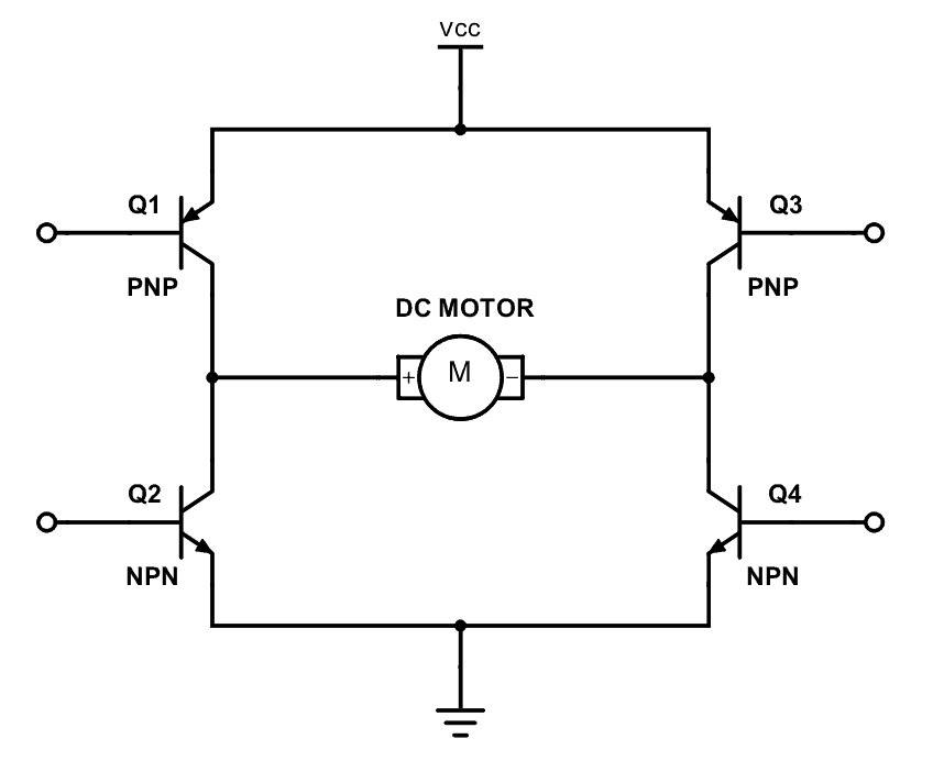
Build Electronic Circuits
An H-bridge is a simple circuit that lets you control a DC motor to go backward or forward. Learn how it works with this simple guide.
 proud sage
hello! I'd like to use the full TinyUSB library (USB host mode) on RP2040, while still staying in Arduino for an Airlift ESP32 support. Would including that library be as simple as #includeing it in my sketch?
or do I have to do extra stuff to include external c/c++ libs
livid osprey
proud sage
hello! I'd like to use the full TinyUSB library (USB host mode) on RP2040, while...
Before I answer that, CircuitPython also supports Airlift ESP32 with ESP32SPI. https://learn.adafruit.com/adafruit-airlift-breakout/circuitpython-wifi

Adafruit Learning System
Give your project an airlift with this WiFi-BLE breakout!
proud sage
yeah, but TinyUSB is also device only in CircuitPython, and including a c library there would mean building cirpy and making my own python library
pine bramble
livid osprey
https://www.build-electronic-circuits.com/h-bridge/
I'm interested in a 1800W brushed motor (~200A at 8ish volt) and couldn't find an arduino/pi h-bridge for that (ie: typical motor on an hobby r/c truck)
livid osprey
But assuming it is compatible, which I don't know offhand, it should just be a matter of using the preprocessor directive #include <TinyUSB.h>.
proud sage
alright, thanks! Time to just try it out then
livid osprey
There also exists https://github.com/sekigon-gonnoc/Pico-PIO-USB for USB Host support.
GitHub
USB host/device implementation using PIO of raspberry pi pico (RP2040). - GitHub - sekigon-gonnoc/Pico-PIO-USB: USB host/device implementation using PIO of raspberry pi pico (RP2040).
pine bramble
The max I could find was 30A and they are 100$ vs an ESC that can do that (but is proprietary and seem top be no way to use it with an arduino and they don't say anything about how to arm it/program it) for 10$
livid osprey
200A.
Yeah, most consumer electronics are NOT rated for currents that high.
I have no idea where that number is coming from, since usually motors rated for 1800W are running something along the lines of 48V 40A...
livid osprey
pine bramble
The max I could find was 30A and they are 100$ vs an ESC that can do that (but i...
Where do you see an 8V 1800W motor?
pine bramble
livid osprey
Where do you see an 8V 1800W motor?
https://www.spektrumrc.com/Products/Default.aspx?ProdID=SPMXSE1150 says 150A (950A Max Burst) 11.1 - 22.2V
There are one motor in RC trucks that use this, 150A * 11.1 ~ 1500W.
Motors are rated in kV and I don't see a stall amp anywhere so I assume they can reach 150ish A at max throttle.
Finally the Drive Motor Sizing Tool from Robotshop says that to carry 20kg on a 20o incline or 40mph speed
I'll need to put up up to 1100W.
this is one with actuall specs: https://hobbyking.com/en_us/turnigy-trackstar-2100kv-1-8th-sensored-brushless-motor.html?queryID=3906e21b231a922638b29566f09feb80&objectID=47138&indexName=hbk_live_products_analytics 2100W

Hobbyking
Turnigy TrackStar 1/8th Sensored Brushless Motor 2100KV
Max voltage: 15V (4S) Max Current: 140A
livid osprey
Oh, I thought you actually meant brushed motor
pine bramble
So I'm trying to make sense of all of this vs what the calculator says
Yeah brushed motors, ie: brushed versions of the motor above
If I can't use the ESC it's pointless considering BLCD motors triphase and the fact than a complex ESC is necessary for them
so with brushed I can skip the ESC and make it myself
livid osprey
Yeah, these brushless motors are basically for actual vehicles. Using an Arduino to control this is not something a tiny L293 motor driver can handle.
You basically need really large discrete circuits with a lot of heat dissipation to manage that much current.
pine bramble
?? no they are used in 1 cubic foot 1:12 r/c ?
1 cubic foot is the size of the robot I'd like to do. I'm not making a tesla-like car
But the above doesn't make sense mathematically
livid osprey
Ok not a Tesla, but an outdoor RC vehicle.
livid osprey
I guess you can make an H-bridge with four relays....?
pine bramble
It seems it's like impossible to connect the r/c world and DIY electronicss world together
livid osprey
Just make sure your contacts won't fuse at the currents you're driving...
pine bramble
I mean even @north stream had problems with his ESC
livid osprey
Impossible, no, just extremely difficult.
pine bramble
So for a newbie like me, with all of them being closed-source/closed-tech, they don't even say how to arm them at all I don't see how I could even use a commercial ESC/receiver
livid osprey
Not generally recommended, either.
Closed source ESCs are often more of a safety thing than they are a top-secret-tech thing. Improper modification of an ESC could lead to disastrous consequences, so it's not generally recommended.
pine bramble
I'm not trying to modify it I jusst need to be able to override the throttle to 0% PWM instead of 100% PWM if the sensors see something close
And autonomous navigation (waypoints)
I mean the classical robotics stuff. With an arduino handle the lower-tech stuf and a pi for the high-bandwidth stuff (lidar/camera)
Maybe I should discuss it in projects or general-tech ?
livid osprey
Or robotics.
pine bramble
there's almost no activity on robotics...
might as well enter a clothes store and ask there...
north stream
pine bramble
It seems it's like impossible to connect the r/c world and DIY electronicss worl...
That's exactly what I've been working on. My transmitter uses a Teensy to read the controls and generate the PPM data stream, which it hands off to the transmitter module. My receiver has a M0 that gets the encoded data as a 115kbps asynch data stream, decodes that into channel data, then generates PWM to control the servos and ESC, as well as running lights and sound on command.
north stream
livid osprey
Impossible, no, just extremely difficult.
See above, it wasn't that difficult once I figured out which modules I wanted to use for the RF link and how to work with their data formats.
pine bramble
which ESC/receiver/motor/transmitter exactly ?
I was able to find some ESC that works with 250ms/1000ms/1500ms/2000ms beeps. Traxxas and Arrma seems to be completely closed (not even manuals)
It seems if I went takima/hobbyking at least I get the timings of the beeps and they sorta like normal PWM (0 to 90 = backward 91 to 99 = neutral 100 to 200 = forward throttle)
I was surprised that almost all of them only use 1 motor and pinion gear to drive all wheel.. That was a bit disappointing
north stream
Transmitter: Lemon RX LMT0002 (DSMP DIY module). Receiver: Lemon RX LM0019N or LM0037. Motor and ESC are whatever the ones are that came in my R/C truck.
pine bramble
I thought the ESC independently drove 4 wheels and 2 independent steering
north stream
Note that is a Traxxas truck, but uses completely standard R/C PWM signalling.
pine bramble
Do you understand my fear of not being able to figure it out and being stuck with a 500$ esc and motors ? 😦
north stream
This truck just has a single motor that drives all 4 wheels via some differentials. However, you could do the same thing with 4 ESCs and 4 motors if you liked.
pine bramble
You seems to be the only one here that ever talk about ESC...
north stream
I imagine there are some R/C Discords out there, but I haven't looked for them.
pine bramble
what is your r/c truck ? Just what brand...
north stream
Traxxas Stampede VXL
pine bramble
I finally got the structural with the gobilda aluminum channels/etc figured. Just neded to figure the motors, but I can't seem to find ones powerful enough for 20kg / 40mph / 1m/s^2 outside the r/c world...
while in the r/c world that seems standards on 1:12 offroad trucks
yeah traxxas supposedly arm between 57 and 60, 1 beep on each...
but nothing in the manuals about that
north stream
Those are some grunty motors. My truck can manage 60MPH, but probably doesn't weigh more than 2kg.
The hard part for me was figuring out how to simulate the Lemon RX binding protocol.
pine bramble
mine wouldn't either it's just to be able to experiment with crane/claw/shovel later and carry a small load or rocks/sand/etc
ie: 2ish kg empty mass, 20kg max. Of course at 20kg I understand it would be much less fast (but can't even find stall amperage of the traxxas motors...)
north stream
There are motors out there with specs like that and really detailed data sheets. However, those motors are $$$$ robotics units.
pine bramble
for the receiver/transmitter is there a particular reason you didn't go with what came with the truck or fully open spec/code/documentation like OpenTX transmister and HeliBL receiver ?
yeah the best robot I found even if money wasn't an issue use a spring/reinforced kraton as a base (which has a 2.2 kw motor) and 1:5 scale
north stream
There's also this beast: https://www.allelectronics.com/item/dcm-2460/24-vdc-brushless-motor-600-watt/1.html

All Electronics Corp.
MAC-BMC P/N 12570-3. Powerful brushless motor with built-in 30A motor speed controller. Designed for electric scooters. Great low-end torque. Requires 5K Ohm potentiometer or Hall-effect throttle to interface with speed control. Great motor for battlebots, hobbyists and experimenters.• No-load Specs: 2480 RPM @ 24.6 VDC, 3A 100 kV•...
The built-in ESC is a very nice bonus
And the built-in electronic brake is super useful for a panic switch, collision detector, etc.
pine bramble
that seems interesting except for the low kV, seems like it will be a big battery eater
whereas if I have says 4800 kV I can play with the gear to gain carrying capacity at the expense of the speed
I bookmarked it anyway. From what I understand brushed don't even really need an ESC. Only brushless because off hall sensors etc
north stream
It is brushless. I bought one, I really like it. Smooth, quiet, and powerful.
Note that brushless motors don't necessarily need hall sensors, most of the cheaper ones are sensorless, and need a smarter ESC that can derive the position data from the back EMF of the coils instead.
pine bramble
what is the need of an ESC then? Serve as a relay to got those hundreds of amps ? User safety (wheels going off while user is programming the ESC / electrical safety) ?
oh ya forgot to mention the reason the new traxxas ESC / transmietters don't have docs is because you bind them by pressing a button on both at around the same time
I'm going to visit an R/C store this weekend and see if they have some ideas of some that would be more open because I've been trying to figure out that part for the last 6 months...
north stream
A brushless motor still needs an ESC, hooking one up to a power supply without one won't result in much of anything useful happening.
I only needed to figure out the binding protocol because I wanted to save size, weight, power, and (most of all) money by using a satellite receiver without the main receiver it normally connects to. After doing some research and experimentation, I was able to do that with an ordinary microcontroller.
pine bramble
I wouldn't mind getting an r/c and using everything in it. It' just that I don't see how I'll be able to do anything not knowing the frequency, crypt algorithm / protocol of the transmietter/receiver. I know it should be PWM. But the lack of documentation from some maker seems to suggest it's going to be something like AES-256
and since I need to get between the transmitter and receiver (or between the receiver and ESC) and between the ESC and motors they might also be on proprietary protocols/encrypted too
some of them have digital servos...
north stream
I pretty much treat the RF protocol as a black box. However, most of them are fairly similar (there are only 4 popular chips in use for the current 2.4GHz units). I probed my transmitter to see how it works, it basically has two chips, one is a microcontroller that accepts the PPM data and converts it into a digital data stream, which it hands off to the RF chip to transmit to the receiver. The receiver simply demodulates it and delivers the data stream.
If I wanted to, I could probably unsolder the data link in the transmitter and just send it asynch serial data directly and skip the PPM step entirely.
pine bramble
I see, so since they use one of 4 chips they all use about the same protocols ?
north stream
So it would seem, but I haven't investigated closely.
For what it's worth, I took apart my Traxxas receiver and found it's using a CC2640 chip for the RF section.
The CC2640 and relatives (Traxxas, FrSky, Futaba) seem to use Bluetooth. The A7105 (FlySky, Hubsan) uses FSK/GFSK. The CYRF6936 (DS, Walkera) uses DSSS and GFSK. The nRF24L01 (HiSky, Syma, Assan, most Chinese R/C models) uses GFSK. The CC2511 (Pololu Wixel) is an interesting oddball with an 8051 core and 2-FSK/GFSK/MSK protocols. That last one could be appealing if you want a fully open solution and don't mind programming in 8051 code (sdcc is available if you want to program it in C)
pine bramble
north stream
The CC2640 and relatives (Traxxas, FrSky, Futaba) seem to use Bluetooth. The A7...
I'll take a look at this information and will ask around IRL as well.
 misty gale
Hello there, i'm developing a board with Adafruit_PN532 NFC reader, but can't find any good documentations
Its there any?
crystal frigate
livid osprey
What booster and amplifier are you using? Is your booster rated for the current ...

Adafruit Learning System
Add digital-quality audio with a class D amplifier for easy sound!
I'm thinking of switching my current off-brand one to something like this.
my goal is to produce something ready for market.
crystal frigate
alright yall. judge my schematic making skills LOL
 cedar mountain
crystal frigate
alright yall. judge my schematic making skills LOL
cedar mountain
crystal frigate
alright yall. judge my schematic making skills LOL
I won't critique the aesthetics, but the one thing that looks genuinely wrong or confusing is how the top gray horizontal line is going through all the MX pins... it's not clear which one(s) it is connected to.
crystal frigate
Ah. I can see how that would be confusing. It is supposed to be ground
pine bramble
Is this something that can be figured out without docs ?

I'm just a bit confused about the wifi (is it an access point or do I need to configure it somehow with an ssid / password throught arduino code to connect to something) ? And B) one analog_read only, so I guess max 1 IC2 sensor and 1 normal analog sensor ?
This is the cheapest semi-modular/arduino compatible/wifi MCU I could find so that I can hopefully I can order 12 to 16 for my home iot sensor boxes cloud around my home
C) I'm kinda confuse by twice the number of required headers, do they want peoples to have extra or ?
wind drift
question - I am trying to display an image on a color display.
I use this site to convert the image to a c array. But the colors come out weird.
north stream
pine bramble
I'm just a bit confused about the wifi (is it an access point or do I need to co...
I believe it can be configured either way, as an access point, or to join an existing network.
north stream
pine bramble
C) I'm kinda confuse by twice the number of required headers, do they want peopl...
It apparently comes with three sets of headers, male ones, female ones, and "stacking" (both male and female), so you can attach whichever set meets your needs.
stable forge
pine bramble
Is this something that can be figured out without docs ?
ESP8266 is kind of obsolete. The analog pin is 0-1v. Some GPIO pins are used for special purposes. See https://learn.adafruit.com/adafruit-huzzah-esp8266-breakout/pinouts for example. TLS doesn't work very well because there's no helper encryption hardware. I think I2C is done by bit-bang. You would be better off with at least an ESP32 (plain ESP32 module) breakout instead.
The ESP32-C3 is kind of the lowest-cost replacement. It also has limitations, and it's very early in its development cycle.
cedar mountain
wind drift
question - I am trying to display an image on a color display.
I use this site ...
Sounds like there's a mismatch in the color format, like RGB order versus BGR order, or different number of bits allocated to each color.
 ionic scaffold
Does anyone here know of a good way to use I2C to communicate between two feather boards? I'm planning a project and wondering if it's already something that's implemented
livid osprey
ionic scaffold
Does anyone here know of a good way to use I2C to communicate between two feathe...
https://www.instructables.com/I2C-between-Arduinos/ shows a similar example setup with two Arduinos instead of Feathers. Same concept should apply.
ionic scaffold
Ok cool I'll check it out ty
elder hare
so i have a matrix display 64x64 and i got it go from
Left to Right
Right to Left
Top to bottom
Bottom to Top
with this code
        if ( PatternDirection == LEFT || PatternDirection == RIGHT )
        {
            for (int i = 0; i < scanLineSize; i++)
            {
                for (int y = 0; y < VPANEL_W; y++)
                {
                    int pi = PatternPosition + i - scanLineSize;
                    effects.leds[XY(pi, y)] = currCollor;
                }
            }
        }

        if ( PatternDirection == TOP || PatternDirection == BOTTOM )
        {
            for (int i = 0; i < VPANEL_H; i++)
            {
                for (int y = 0; y < scanLineSize; y++)
                {
                    int pi = PatternPosition + y - scanLineSize;
                    effects.leds[XY(i, pi)] = currCollor;
                }
            }
        }
but im having a hard time to make it go from
TopLeft to BottomRight
TopRight to BottomLeft
how would i do that?
 native dagger
Can the same adafruit board address more WS2811s in arduino than CP?
cedar mountain
I'd expect so, since more RAM would be available.
stable forge
native dagger
Can the same adafruit board address more WS2811s in arduino than CP?
well, there might be more RAM for the buffers that are needed
but how many are we talking about?
and which board?
native dagger
Unsure of both. I was hoping for a qt py board. Maybe 400 split across 4 separate pwm lines and power lines
stable forge
that should really be fine with CircuitPython. I'd suggest an RP2040 so you have plenty of programming elbow room
stable forge
you may want level shifters, or you could use the trick of powering the very first neopixel at a lower voltage and have it do the level shifting
native dagger
I'd be doing a board so level shifting wouldn't be an issue.
 pallid grail
@leaden walrus Hello, are you around?
Your yellow idle moon says no, but half the time you simply haven't touched Discord in a bit, so I figured I would try.
I'll ping Limor. 🙂
leaden walrus
@pallid grail yo. back.
pallid grail
@leaden walrus Ok maybe you know. Limor's busy it seems, as usual. I am doing the guide for the QT Py ESP32-Pico. It comes with 8MB of flash. For CP, there's a chunk set aside for firmware, and separate chunk for filesystem. Does Arduino do or need anything like that? Or is it simply available space?
leaden walrus
just available space, in general
only other thing would be a bootloader
there's no filesystem, unless explicitly done via sketch
pallid grail
I'm not sure it has one. JP couldn't get to one when he was trying, while forgetting that it doesn't run CP.
Ok.
 obtuse wedge
Guys I have this n-mosfet here. https://br.mouser.com/datasheet/2/427/sira18adp-1761556.pdf I thought it would work fine on 3v3 but its only giving me heat. Why?
https://tinyurl.com/22y3u4h5 this is the circuit I'm using it. Its driven by 3v3 and its driving a 10ohm load on 24V
I thought that with 3.3Vgs the Rds(on) would be super high like 20mOhm and with a current of 2A the mosfet would dissipate 0.115W max
 crystal frigate
So I'm working on a toy project for mass manufacturing, and it has these "bumper" buttons on the front. Right now they are cherry mx switches but I need a solution to mount them 90 degrees onto my board
The main board lays flat in the base, but the buttons need to be held up 90 degrees. While I could get away with just simple wires, this is a kids toy so I would prefer that they were directly mounted onto the board
 pine bramble
stable forge
ESP8266 is kind of obsolete. The analog pin is 0-1v. Some GPIO pins are used for...
pine bramble
stable forge
ESP8266 is kind of obsolete. The analog pin is 0-1v. Some GPIO pins are used for...
eh well gotta save costs somewhere a feather with oled cost me 40$ with shipping and duty each. Where with an oled thist cost less than 15$
i mean these are for volume purchase to have a couple of 1-2$ sensors always on
pine bramble
stable forge
that should really be fine with CircuitPython. I'd suggest an RP2040 so you have...
Maker of the board (LOLIN D1 mini) says the analog pin is 3.3V. Is it possible the adafruit version is 1.0V ?
"Hardware Design The input voltage range is 0 to 1.0 V when TOUT is connected to external circuit." sigh
6th purchase order out of the window. I guess I'll get some lego mindstorms and be done with electronics...
I guess that's why they have a super simple chip like the DHT11 on a breakout...
north stream
obtuse wedge
Guys I have this n-mosfet here. https://br.mouser.com/datasheet/2/427/sira18adp-...
This graph in the data sheet tells the tale. The on-resistance doesn't start to get low until you get to a gate voltage of over 4 volts. 3.3V will leave it in a moderately high resistance state.
 pine bramble
Bah I give up
north stream
You can make a voltage divider out of two resistors to convert a higher voltage signal to a 0-1V range.
pine bramble
Apparently in 2022 with the parts and chips shortage and Canada being isolated from reasonable price from shipping it seems I have to use 100$ texas instruments MCU (that always seems to be in stock even thought they are from the 1980 and are much less capable than rev1 of arduino)
north stream
Free shipping can be had in Canada. I like some of the more recent TI MCUs.
obtuse wedge
north stream
This graph in the data sheet tells the tale. The on-resistance doesn't start to...
yes man, thank you very much I've see it too.... unfortunately it wont be possible without a gate driver or circuit.
north stream
obtuse wedge
yes man, thank you very much I've see it too.... unfortunately it wont be possib...
Or a transistor that conducts better at 3.3V on the gate
 quartz river
If I have a light flickering at over 100 times per second, will a generic photoresistor be able to accurately detect that flickering, and transmit that data to an Arduino. Like, if I had an Arduino Mega connected to it, would the Arduino be accurate enough to be able to do something every time it went on/off?
(it came in a generic Arduino kit, so I don't know the model of the photoresistor)
north stream
Ordinary cadmium sulfide photocells are fairly slow-responding and may not work well, but a photodiode or phototransistor should manage easily. If you want to read it as analog, I think the ADC bandwidth is sufficient but I'm not sure. If you just wanted a digital pulse, you could have an interrupt driven routine to do something (but it would have to be something brief and simple)
The cadmium sulfide ones look like this: https://www.adafruit.com/product/161

CdS cells are little light sensors. As the squiggly face is exposed to more light, the resistance goes down. When it's light, the resistance is about ~1KΩ, when dark it goes up to ...
quartz river
I have a phototransistor, but it only has two connectors. Here is more or less what it looks like (I'm re-using some Snap Circuits parts)
 quartz river
north stream
Ordinary cadmium sulfide photocells are fairly slow-responding and may not work ...
quartz river
north stream
Ordinary cadmium sulfide photocells are fairly slow-responding and may not work ...
Would this one work...?
inland gorge
quartz river
I have a phototransistor, but it only has two connectors. Here is more or less w...
Yes, phototransistors are very good at fast signal detection. They're what's in your TV's IR remote receiver picking up your TV remote's 38kHz "flickering" IR LED
quartz river
inland gorge
Yes, phototransistors are very good at fast signal detection. They're what's in ...
Do “normal” ones exist that just detect regular light from an LED as opposed to IR…?
inland gorge
Even IR phototransistors detect normal light a good amount, but yes they do exist. But the IR ones are really common
quartz river
inland gorge
Even IR phototransistors detect normal light a good amount, but yes they do exis...
I can try an IR if you think it will work
inland gorge
quartz river
I can try an IR if you think it will work
Yeah give it a go. Also most lights put out a little IR too
quartz river
inland gorge
Yeah give it a go. Also most lights put out a little IR too
I have a blue LED that I intend to use
Will IR go over a fiber optic cable? Or only regular light…?
inland gorge
quartz river
I have a blue LED that I intend to use
ah well that might not work. LEDs are very single color and blue is far away from infra-red
quartz river
If IR can go over fiber, I could sacrifice a remote
inland gorge
quartz river
Will IR go over a fiber optic cable? Or only regular light…?
yes, most IR is close to visible light, so things like fiber optics and mirrors work just like normal light
(there's "far IR" that is basically heat radiation, but things like LEDs and phototransistors don't do far IR)
quartz river
inland gorge
yes, most IR is close to visible light, so things like fiber optics and mirrors ...
I’ll try that. The cable is from Snap Circuits but mu goal is to get 1KB/s over a DIY fiber optic system with two Arduinos. A photoresistor works but is way too slow
 inland gorge
neat!
your idea should totally work and you can probably prototype it with the LED & phototransistor next to each other, not even hooked up to the fiber (this eliminates the fiber attachment challenge so you can verify your circuits works)
quartz river
inland gorge
your idea should totally work and you can probably prototype it with the LED & p...
I’ll try that. I’ll take an LED from an IR remote and try a phototransistor and see how far I can get, but I can try it without the cable. I’ll probably DIY some fiber connector of some sort that nicely connects to an LED or phototransistor
north stream
quartz river
I’ll try that. I’ll take an LED from an IR remote and try a phototransistor and ...
One easy way is to use soft tubing (like silicone) or heat shrink to hold them together.
livid osprey
crystal frigate
So I'm working on a toy project for mass manufacturing, and it has these "bumper...
Usually, buttons like https://www.digikey.com/en/ptm/e/e-switch/right-angle-and-edge-mount-switches are used for this kind of application, but there really isn't a Cherry MX equivalent. Best I could think of would be to connect a small daughterboard with a combination of vertical and right angle connectors to mount your keyswitch.
This presentation will explain the difference between a right angle switch from an edge mount switch along with advantages to both.
livid osprey
pine bramble
"Hardware Design The input voltage range is 0 to 1.0 V when TOUT is connected to...
The Analog input is 0-1V on the chip itself, but the module has a voltage divider that extends it to 3.3V.
 pine bramble
livid osprey
The Analog input is 0-1V on the chip itself, but the module has a voltage divide...
pine bramble
livid osprey
The Analog input is 0-1V on the chip itself, but the module has a voltage divide...
module mean the rest of the board ?
livid osprey
The LOLIN D1 mini board, yes.
Well, to be precise, it actually seems to go up to 3.2V, unless you add an additional 10k resistor in series.
pine bramble
The 2 things I'm not sure about are: 1) if I use an analog sensor that is from 0 to 3.3V will it works correctly ? 2) If the sensor operating voltage is says 2.8V to 6V will it burn the pin ? Assuming it's not a mosfet if I don't send it over 3.3V I don't see why I should get more than 3.3V back ? 3) It has a voltage step-down from 5V to 24V I think. Which seems to mean I have to use 5xAA but I can't use 3/4x AA (I have 1.2V NiCd and alkaline 9V in stock)
livid osprey
pine bramble
The 2 things I'm not sure about are: 1) if I use an analog sensor that is from 0...
- You may need to add a 10k resistor to clean up the top end of the sensor range, but there shouldn't be an issue.
- If operating voltage refers to the power supply range, you should be fine if you power it with 3.3V. I would need to see the datasheet to determine if the other outputs are regulated, but there shouldn't be any issues using it.
pine bramble
What about 3? I'm looking at the battery holders atm. Arduino kinda have the same "dead-zone" between 5 and 7V
above 7V is fine but now between 5 and 7V, this ones seems to have a deadzone between 3.3 and 5 too...
livid osprey
Again, not sure how the power is regulated, unless you provide a datasheet (or at least a part number)
Most step-down converters are marketed for a single voltage, but realistically can handle at least a small range of voltage.
pine bramble
This is the part on whih I can hardly find any information, there is a big warning to not exceed 3.3V. But some revisions come with a 5V/1A adapter. Apparently at these prices (4$ for a MCU) it doesn't come with a datasheet really
since it supports USB Type-C it's pretty much a given that 5V is fine
But batteries don't have a static voltage
and this isn't of much use to me if I have to plug them into outlets with a 5V power supply
livid osprey
OH, I thought you were talking about the sensor...
The LDO from VBUS is rated to a maximum of 6.5V, so anything from 4.3-6.5V should work in theory.
That should be happy with 3-5 AA, depending on battery chemistry.
pine bramble
Hum question 1) is resolved for me. 3) was about the power supply for the board on which the MCU is. 2) was about if the sensor operate at 2.8 to 4V and possible return 4V analog for some values it can senses. Since there are no mosfets in analog sensors afaik they should be limited to 3.3V even if they read higher
livid osprey
Dunno where you see a 24V/5V step-down...
and that would depend on the sensor. Some chips do have internal regulation, others just output 0-VCC.
Again, no part number, no help haha
pine bramble
adafruit used to sell some of these chips a long time ago.
the 24V thing was because there was a dc power supply shield for it.(https://www.wemos.cc/en/latest/d1_mini_shield/dc_power.html) and one for lithium battery (Charging Voltage: max: 10V, recommend: 5V
Charging Current: max: 1A Lithium Battery voltage: 3.3-4.2V Boost Power Supply: 5V(max: 1A))
Sorry for the confusion
pine bramble
livid osprey
Again, no part number, no help haha
Since the docs is schematic I thought that was even better than datasheets but I guess not...
livid osprey
Wait, that was for the sensor output
pine bramble
Is there a problem with me asking 3 questions and giving them numbers ? Or do you want me to go question by question ?
livid osprey
Nonono, the problem isn't the numbers, its about you having two separate subjects and not establishing which part the question is related to haha
If all of the questions are focused on the Wemos D1 mini, I apologize for misunderstanding
pine bramble
They aren't two separate subjects thought, I don't want to blow the board out by powering it with too much voltage or having a sensor sends up too high voltage as measurement
Yeah they are all focused on the wemos d1 mini with the esp-8266EX
livid osprey
The range of analog input is adjustable by means of adding extra resistance to your ADC pin in series. The Voltage divider onboard is 220k/100k, but if you need to raise that limit you can add more resistance to the A0 pin
Does the sensor return 4V readings?
pine bramble
I have 31 sensors, I'm just hoping it works with all of them including the ones that operates from 2.4V to 6V and could return 6V if according to what they sense it correspond to 6V in the specs of the sensor
I mean if the analog sensor datasheet says when it see blue it sends out 6V that will probably blow the board is what I assume in a nutshell
Even thought I only send 3.3V to it
livid osprey
Can you send me the sensor datasheet/part number?
pine bramble
Was just a generic question about sensors when one have a 3.3V board. I guess I'll find a specific one then and asks again...
livid osprey
Most analog output sensors have a fixed, semi-continuous range. Anything dealing with multidimensional sensing usually uses either multiple analog channels or some form of digital interface.
quartz river
north stream
One easy way is to use soft tubing (like silicone) or heat shrink to hold them t...
I can try that. I was considering something like the one for optical audio, albeit quite a bit simpler
pine bramble
and got that d1 mini kit, hopefully a few things works and I can use the rest as solder practice...
 tranquil shell
I get lots of python errors when trying to use the adafruit extensions to arduino for nrf52840 ble express
is ths the right place to ask for help ?
it's not circuitpython or anything on the nrf52840, it's the build environment
solemn cliff
tranquil shell
I get lots of python errors when trying to use the adafruit extensions to arduin...
can you tell us more ? what version ? what OS ? what error, etc ?
tranquil shell
Sorry, was trying to avoid flooding with irrelevant details if I'd got the wrong place
linux mint, arduino 1.18, adafruit nrf52 1.3.0
it compiles an example Ok but fails when downloading. I will capture the load error in a moment (I've changed a fw thigs trying to make it work)
attempts to fix it from suggestions on the web broke pip3
solemn cliff
a random guess would be that there's a tool in the NRF toolchain that requires python, and you might either have python 2 installed or not have python made to call python3 or something like that
but that all depends on what the error is
tranquil shell
I have pythin 2.7 and two versions of pythoin3 installed but you are roughly correct. My experience of python is that it always breaks unless you develop locally
solemn cliff
python virtual environments can be a saver, but also hard to juggle
stable forge
tranquil shell
I have pythin 2.7 and two versions of pythoin3 installed but you are roughly cor...
This is you, I think: https://github.com/adafruit/Adafruit_nRF52_nrfutil/issues/17
how old is your linux mint?
python 3.5 is quite old
tranquil shell
so I understand, but installations like adafruits never use them
stable forge
what is the system version of python on your computer?
tranquil shell
2.7 and 3.5 i think. it;s mint 18.3
stable forge
that was end of life in April 2021
If you can get Pyton 3.7 or later installed in a venv or whatever, that would help a lot.
tranquil shell
yeah but it's reliable :)
i doi have 3.7 installed. i could probably get it invoked
but maybe uts time to update mint. I just did a debian update on another machine and found it no loner supported my video card :(
the differnces between early python 3 and recent ones seem to be just as bad as the 2.7 - 3 debacle
stable forge
well, we use convenient features of more recent pythons
tranquil shell
yes. that's unfortunate. it causes an update mill.
There was good advice in older days for writing portable code in Henry Spencer's 10 commandmanets
I understand how it all happens. But then you et something like adafruits tools that make assumptions that aren't valid.
if it requires 3.7 it should check for that and say so, not just collapse in a stack dump
so, basically, I need to update mint or I;m in a world of pain ?
stable forge
I think pip warned you to update, did it require you to update?
tranquil shell
no, but it also didn't tell me of the consequences
stable forge
that's pip's issue. Try rolling pip back and maybe it will all work
tranquil shell
It was too broken to roll back. I had to delete ~/.local
stable forge
the pip you updated to uses f-strings
stable forge
well, it's that the new pip you upgraded to uses them; it's not that adafruit-nrfutil uses them
tranquil shell
after performing the update, pip was so broken it couldn't even report the version
stable forge
you still have the system version of pip, though?
tranquil shell
yes
stable forge
so I think you could start over here, and I think adafruit-nrfutil will be ok. It deliberately doesn't require a bunch of new stuff. Just ignore pip's plaintive recommendations to upgrad
tranquil shell
right.
yes your right that the link is me. I just about recovered the pip situation and came looking for other help befoe I fell down too deep a rabbithole
obtuse wedge
guys most common smd package for power mosfet?
tranquil shell
@stable forge so pip3 is working and installing adafruit-nrfutil ran without errors.
it was the original problem I had, but now there is a different error
stable forge
obtuse wedge
guys most common smd package for power mosfet?
suggest you ask in #help-with-hw-design
tranquil shell
Traceback (most recent call last):
File "/usr/local/bin/adafruit-nrfutil", line 7, in <module>
from nordicsemi.main import cli
File "/usr/local/lib/python3.5/dist-packages/nordicsemi/main.py", line 32, in <module>
import click
File "/usr/local/lib/python3.5/dist-packages/click/init.py", line 7, in <module>
from .core import Argument as Argument
File "/usr/local/lib/python3.5/dist-packages/click/core.py", line 83
f"{hint}. Command {base_command.name!r} is set to chain and"
^
SyntaxError: invalid syntax
exit status 1
Error compiling for board Adafruit Feather nRF52840 Express.
obtuse wedge
stable forge
suggest you ask in <#656770973852237844>
sorry of course
stable forge
np
tranquil shell
which again looks like an f-string
stable forge
that is in click, so maybe something is wrong with click's version requirements, or maybe reinstall it back a bit
tranquil shell
what does click do ?
stable forge
command-line argument parsing
modern equivalent of optargs getargs, etc
f-strings were introduced in python 3.6
can you easily create a venv for python 3.7 or later?
tranquil shell
not easily but maybe after some reading
stable forge
do pip list and see what version of click you have
tranquil shell
man venv
No manual entry for venv
stable forge
virtualenv then
tranquil shell
nah, i think it's just they didnt write a manpage
also it wasnt installed on this machine
stable forge
is some later version of python available for your version of mint?
you can install it with apt; it won't replace the system one
tranquil shell
yes, i have a 3.7 installled but it has to be invoked specifically
stable forge
do python3.7 -m venv venv3.7, which will create a venv in the venv3.7 directory
tranquil shell
ok did that
stable forge
then do source venv3.7/bin/activate, and presto, you are inside the venv, with python3.7 as the default
python3 --version should confirm
then you can pip3 install merrily in there. Note that you have to do source; it changes paths, etc.
tranquil shell
click is 5.1 and 8.1.3
stable forge
in the python 3.5 world or the venv?
tranquil shell
5.1 in the default 2.7, 8.1.3 in pip3 and in the venv
source venv3.7/bin/activate
(venv3.7) adrian@angua ~ $ pip3 install click
Collecting click
Using cached click-8.1.3-py3-none-any.whl (96 kB)
Collecting importlib-metadata; python_version < "3.8"
Using cached importlib_metadata-4.11.4-py3-none-any.whl (18 kB)
Collecting zipp>=0.5
Using cached zipp-3.8.0-py3-none-any.whl (5.4 kB)
Collecting typing-extensions>=3.6.4; python_version < "3.8"
Using cached typing_extensions-4.2.0-py3-none-any.whl (24 kB)
Installing collected packages: zipp, typing-extensions, importlib-metadata, click
Successfully installed click-8.1.3 importlib-metadata-4.11.4 typing-extensions-4.2.0 zipp-3.8.0
stable forge
so now you can install adafruit-nrfutil in the 3.7 venv and should be able to use it
I think something is messed up in the 3.5 world: you should not have click 8.1.3 there, I think
tranquil shell
but that should be ok. 8.1.3 just doesn't work with 3.5
stable forge
but it seems like it got installed in your default 3.5 world
I think you said that?
https://pypi.org/project/click/ says 8.1.3 requires >= 3.7
tranquil shell
seems to be yeah. may have been detritus from me on some previous attempt to fix something
stable forge
anyway, the 3.7 world is nice and fresh and should work
tranquil shell
so i've done the pip upgrade there too, and the adafruit-nrfutil install. presumably I have toi run arduino inside it too ?
tranquil shell
OK so it got a bit further
error list dooesnt fit in discord
but it wants me to upgrade the bootloader and something else
ive seen instructions about the bootloader. may be able to do that.
downloader has replaced bootloader after i put it in dfu mode
but that bricked it. no more /dev/ttyACM0
i can get it to show a uf2 though
not sure if that helps
can#'t i use arduino's nrf52840 support ? This seems a bit beta
If I build and load blink, it succeeds (except it doesn't blink .. possibly needs a different port pin)
but asciitable (for a simple virtual uart) doesn't build
Upgrading target on /dev/ttyACM0 with DFU package /tmp/arduino_build_614570/Blink.ino.zip. Flow control is disabled, Single bank, Touch disabled
########################################
Activating new firmware
Device programmed.
asciitable :
/home/adrian/.arduino15/packages/adafruit/tools/arm-none-eabi-gcc/9-2019q4/bin/../lib/gcc/arm-none-eabi/9.2.1/../../../../arm-none-eabi/bin/ld: sketch/ASCIITable.ino.cpp.o: in function setup': /home/adrian/Apps/Arduino/arduino-1.8.19/examples/04.Communication/ASCIITable/ASCIITable.ino:24: undefined reference to Adafruit_USBD_CDC::begin(unsigned long)'
/home/adrian/.arduino15/packages/adafruit/tools/arm-none-eabi-gcc/9-2019q4/bin/../lib/gcc/arm-none-eabi/9.2.1/../../../../arm-none-eabi/bin/ld: /home/adrian/Apps/Arduino/arduino-1.8.19/examples/04.Communication/ASCIITable/ASCIITable.ino:25: undefined reference to Adafruit_USBD_CDC::operator bool()' /home/adrian/.arduino15/packages/adafruit/tools/arm-none-eabi-gcc/9-2019q4/bin/../lib/gcc/arm-none-eabi/9.2.1/../../../../arm-none-eabi/bin/ld: /home/adrian/Apps/Arduino/arduino-1.8.19/examples/04.Communication/ASCIITable/ASCIITable.ino:30: undefined reference to Serial'
/home/adrian/.arduino15/packages/adafruit/tools/arm-none-eabi-gcc/9-2019q4/bin/../lib/gcc/arm-none-eabi/9.2.1/../../../../arm-none-eabi/bin/ld: sketch/ASCIITable.ino.cpp.o: in function loop': /home/adrian/Apps/Arduino/arduino-1.8.19/examples/04.Communication/ASCIITable/ASCIITable.ino:43: undefined reference to Adafruit_USBD_CDC::write(unsigned char)'
/home/adrian/.arduino15/packages/adafruit/tools/arm-none-eabi-gcc/9-2019q4/bin/../lib/gcc/arm-none-eabi/9.2.1/../../../../arm-none-eabi/bin/ld: /home/adrian/Apps/Arduino/arduino-1.8.19/examples/04.Communication/ASCIITable/ASCIITable.ino:71: undefined reference to `Serial'
collect2: error: ld returned 1 exit status
exit status 1
Error compiling for board Adafruit Feather nRF52840 Express.
 sudden vine
Just picked up a pyPortal. I realize it's designed to run python but I'd also like to figure out how to run Arduino code on this thing. I found this test called PyPortal_ArduinoSelfTest.ino which is encouraging. I just can't seem to find out which board definition to use for compilation 😳 .
sudden vine
wowza i only had loaded the "Arduino SAMD" boards and my brain overlooked that. thank you!!
stable forge
@tranquil shell there should have been a UF2 bootloader on the board already. It's a superset of the Arduino bootloader. Not sure why you wanted to upgrade the bootloader.
sudden vine
@leaden walrus THX .... that compiles, uploads, and demo works! my mind just blanked on that part (probably because it wasn't necessary to get rolling with the default python demos)
leaden walrus
np. it's confusing. since there are two BSPs to install.
doesn't help that Arduino and Adafruit look similar
pine bramble
Arduifruit 🍏
leaden walrus
not the first time this has happened
sudden vine
Let the fun begin!! Might have another question soon about the default shipped board not working with WPA2 (wifi) only WPA (less secure) but I think I can figure that out.
tranquil shell
@stable forge it was the BSP that wanted to upgrade the bootloader. I think there are some notes about it in the 52840 section on adafruit website.
If there's something there I can probably fix it. Ive got a Segger at home but not with me atm
It did this and then various other problems that I think were just becuse the serial port was gone.
Sketch uses 21248 bytes (2%) of program storage space. Maximum is 815104 bytes.
Global variables use 3100 bytes (1%) of dynamic memory, leaving 234468 bytes for local variables. Maximum is 237568 bytes.
Upgrading target on /dev/ttyACM0 with DFU package /tmp/arduino_build_614570/Blink.ino.zip. Flow control is disabled, Single bank, Touch disabled
Failed to upgrade target. Error is: Serial port could not be opened on /dev/ttyACM0. Reason: [Errno 16] could not open port /dev/ttyACM0: [Errno 16] Device or resource busy: '/dev/ttyACM0'
Traceback (most recent call last):
File "/home/adrian/venv3.7/lib/python3.7/site-packages/serial/serialposix.py", line 322, in open
self.fd = os.open(self.portstr, os.O_RDWR | os.O_NOCTTY | os.O_NONBLOCK)
OSError: [Errno 16] Device or resource busy: '/dev/ttyACM0'
During handling of the above exception, another exception occurred:
Discord objects to more than 2k posted. Nit sure it's worth cutting multiple bits in.
north stream
quartz river
I can try that. I was considering something like the one for optical audio, albe...
This article may give you some ideas: https://makezine.com/projects/how-to-connect-optical-fibers-to-leds-and-sensors/

Skip the store-bought couplings and make these easy DIY fiber optic hookups.
crystal frigate
livid osprey
Usually, buttons like https://www.digikey.com/en/ptm/e/e-switch/right-angle-and-...
That's probably a good idea. I'll have to run it by my enginner guy
gentle meteor
How can I find out how much to move my mouse with the mouse library for each button push?
quartz river
north stream
This article may give you some ideas: https://makezine.com/projects/how-to-conn...
I like that design. I also found these which are simaler https://www.robotshop.com/uk/replacement-fiber-optic-cable-holder-black-snap-circuits.html
north stream
Good find, and cheaper than actual Toslink assemblies, which aren't too expensive, but they're still several bucks apiece.
quartz river
north stream
Good find, and cheaper than actual Toslink assemblies, which aren't too expensiv...
Yeah… those are from Snap Circuits, but I was considering taking like a cedar block, cutting it to be maybe 1” by 1cm by 1cm and drilling a small hole for the fiber in one end and a bigger hole for an led in the other end
north stream
Sounds workable to me.
native dagger
What's the simplest, in terms of external components and pins (I need 3 GPIO) MCU that will run arduino? Doesn't even need usb, a programmer is OK
I need to monitor an input and change two outputs based on it, and do debouncing.
Attiny?
stable forge
native dagger
Attiny?
I think that would be the simplest. https://github.com/SpenceKonde/ATTinyCore
supports many of them
native dagger
A qt py would work but...it's pretty overkill
stable forge
classic trinket is attiny
stable forge
there are other boards with attiny, people do try to make them really small
north stream
As small as possible might be an ATtiny10, which is available in a miniscule package (I think a 6-pin SOT-23)
stable forge
we are using ATTiny817 for things due to not being able to get SAMD09 easily. Breakout board: https://learn.adafruit.com/adafruit-attiny817-seesaw Too big for you, but easily applicable to other Attiny
north stream
 native dagger
Is the 10 really limited? I think a pile of old laundry could do the calculations I need but still
stable forge
https://forum.arduino.cc/t/attiny10-on-the-arduino-ide-solved/579604/7 ... not really "solved"
north stream
It works, but I don't think there's support for it in Arduino. Ben Heck has a bunch of videos about it.
north stream
More like straight C. With only 32B of RAM, there's not a lot of room for fanciness.
Still, it's a powerhouse compared to a PIC12
native dagger
Yeah I might want more than that
Given the attiny85 is fairly smol, I can probably just use that
The 10 is cute tho
pine bramble
and about to buy 4x adafruit esp-32-s2 qt py, just need to solve the mix of stemma QT cables...
also got 2 ToF sensors from 25mm to 6000mm
north stream
Support for the tiny85 is pretty solid, and it works well. I still build those classic Trinkets into things.
 pine bramble
is that extruded aluminum ??
 pine bramble
still no grand central m4 though 😦 😢
maybe I should consider a headerless teensy 4.1 or a beagle...
north stream
I also like the Grand Central. I may use one to control a pinball machine (need lots of I/O for that trick)
pine bramble
they had 129 the other day on mouser with free shipping 😦
oh well, spent a lot, should be good for a while and have enough esp32-s2 for 4 sensor box
so there is that
 dense ridge
I've been out of the arduino game a while... on my matrixportal, my sketch isn't loading on board reboot. It only loads if I upload in the IDE every time. Am I missing something obvious?
 restive smelt
Hi I'm looking to re-create the demonstration video for the VEML7700 Lux Sensor. I've ordered all of the products used but I can't find a guide or tutorial to make it work. Thanks in advance
product link: https://www.adafruit.com/product/4162

Vishay has a lot of light sensors out there, and this is a nice simple lux sensor that's easy to add to any microcontoller. Most light sensors just give you a number for brighter/darker ...

One of our star Feathers is the Adafruit HUZZAH32 ESP32 Feather - with the fabulous ESP32 WROOM module on there, it makes quick work of WiFi and Bluetooth projects that take advantage of ...
A Feather board without ambition is a Feather board without FeatherWings! This is the FeatherWing 128x64 OLED: it adds a gorgeous 128x64 monochrome OLED plus 3 user buttons ...
dense ridge
dense ridge
I've been out of the arduino game a while... on my matrixportal, my sketch isn't...
ahh nevermind, I left a serial loop in the code... good times
wind drift
Any ideas how I can fix this weird color issue on this display?
(Image converted to c-array)
 livid osprey
wind drift
Any ideas how I can fix this weird color issue on this display?
(Image converted...
livid osprey
wind drift
Any ideas how I can fix this weird color issue on this display?
(Image converted...
It looks like your conversion tool has the wrong color order for your framebuffer. What converter are you using?
Actually, what code are you using? Is it possible to switch the blue and red color bits?
wind drift
GitHub
A fully featured Arduino library to support the RGB OLED 64x64 Display Breakout using the SSD1357 driver IC. Direct access to display RAM, drawing functions for pixels, lines, rectangles, and circl...
I use the bitmap example in the examples folder
And this converter
livid osprey
wind drift
https://github.com/sparkfun/SparkFun_RGB_OLED_64x64_Arduino_Library
And you have established that the display is, in fact, using an SSD1357 chip?
wind drift
I am not exactly sure but the datasheet states a SSD1357 chip
It's a chinese display
The example images on the sparkfun github look fine though
with correct colors
GitHub
A fully featured Arduino library to support the RGB OLED 64x64 Display Breakout using the SSD1357 driver IC. Direct access to display RAM, drawing functions for pixels, lines, rectangles, and circl...
like this one for example
wind drift
I tried both I believe but I will try again in an hour or so
pine bramble
when you convert an image to C that imply you need to use the code of the converter to put it back to an image before sending ut off to the LCD
wind drift
Little endian


Big endian


any ideas what I could do to invert the red and blue values?
obtuse wedge
wind drift
any ideas what I could do to invert the red and blue values?
are you sure your image is converted to a correct color format?
can you display any image correctly?
wind drift
I am using this converter https://lvgl.io/tools/imageconverter
It's the only one I got to work
The images that display correctly are from the examples
But they are also a c array
pine bramble
yes that tool says you need to convert back the C code to an actual image
using their library
did you?
wind drift
I did not. How exactly would I convert it back? It seems to only export to c and binary
pine bramble
https://www.arduino.cc/reference/en/libraries/lvgl/ you'll have to include it in the arduino library manager and find out how to convert the C code back to an image
The Arduino programming language Reference, organized into Functions, Variable and Constant, and Structure keywords.
Generally a C-code image doesn't exist it has to be converted back by whatever tool let you put it in C first
you'll probably have to convert it for the LCD library as well, never used liquidcrystal so not sure it can
I'm not sure you wanted to convert it to C code though especially when you didn't know you had to convert it back
Could have used base64 for instance if you wanted to keep the image static in code
wind drift
The sparkfun bitmap example says I should paste the c code
When I copy paste the c code from the galaxy example it works fine with correct colors
When I copy paste a custom image it has the wrong colors
livid osprey
wind drift
any ideas what I could do to invert the red and blue values?
Oh that’s not a color order issue, it looks like the pixels are offset slightly. Is it possible that your bytearray has an extra (or missing) byte somewhere?
wind drift
I just copy paste the whole block
formal onyx
I have a custom arduino board that I designed that I've been trying to debug for a few weeks now, I've just noticed that while flashing the atmega16u2 on an official uno using FLIP, the rx and tx lights flash during the flash. But on my custom board, they do not. Despite this, it passes verification and it passes the loopback test so it seems to be flashing correctly? I'd ignore it but im having issues uploading sketches so something must be wrong. When uploading sketches, RX lights up but never TX (so i know the LEDs aren't simply broken) im pretty stuck on this, any ideas? 😦
north stream
formal onyx
I have a custom arduino board that I designed that I've been trying to debug for...
Maybe use a second board to monitor the traffic on the RX and TX leads and see if it looks correct.
terse lava
I'm trying to make a function that checks if a distance sensor is going too close or too far out of a desired value at different levels. Struggling to understand a more streamlined way to say something along the lines of; if value goes out of range by 5, 10, or 15%, do varying things. My goal is to make beeps with a buzzer that increase in count as the current distance goes too close or too far. Here is what I am trying, not sure if this is efficient for this idea:
void checksafeDistance(void) {
  // Less than 5%, beep once. 10%, twice. 15%, 3 times. beep(frequency, amt of beeps)
  if (avgDistance < (0.95 * safeDistance)) {
    Serial.print("5 percent off!");
    EasyBuzzer.beep(400, 1);
  }
  else if ( avgDistance < (0.9 * safeDistance)) {
    Serial.print("10 percent off!");
    EasyBuzzer.beep(400, 2);
  }
  else if (avgDistance < (0.85 * safeDistance)) {
    Serial.print("15 percent off!");
    EasyBuzzer.beep(400, 3);
  }
  // Greater than 5%, beep once. 10%, twice. 15%, 3 times.
  if (avgDistance > (1.05 * safeDistance)) {
    Serial.print("5 percent off!");
    EasyBuzzer.beep(400, 1);
  }
  else if ( avgDistance > (1.1 * safeDistance)) {
    Serial.print("10 percent off!");
    EasyBuzzer.beep(400, 2);
  }
  else if (avgDistance > (1.15 * safeDistance)) {
    Serial.print("15 percent off!");
    EasyBuzzer.beep(400, 3);
  }
  EasyBuzzer.stopBeep();
}
You can precompute some stuff to do over/under together, along with the scaling:
float diff = abs(avgDistance - safeDistance) / safeDistance;

if (diff > 0.15) // 15% off
if (diff > 0.10) // 10% off
That would be so much easier haha
thank you! still struggling with implementing basic mathematics
north stream
We've all been there
terse lava
I really appreciate your help!
Is there any reason you wouldn't want the larger/smaller checks to be else if?
north stream
else if would probably be clearer, yes
pine bramble
terse lava
I'm trying to make a function that checks if a distance sensor is going too clos...
??? If the distance is 0.7 * safedistance wont it go in the first if and same if the distance is above 1.2 * safedistance ? shouldn't you invert the orders of your ifs ?
Or even better make an array of floats and check the range in it ?
north stream
You could make an array of structs that hold the distance ratios and beep parameters and iterate through it in a loop.
pine bramble
also noticed that you didn't use >= and <= is that because you know distance will never be equal to say 1.15 since that number can't be used by a computer because of the limits of the representation of IEEE floating point numbers or it's just a coincidence ?
terse lava
Haha pure coincidence but I will gladly use that tidbit in the future. Could I just do
if (diff > 0.10 && diff < 0.15)```wait that is the wrong scenario
north stream
You could do that too, but I'll usually start with the larger ones, then jump out
If you're curious about the array of structs idea, it would look a little like this:
struct distbeep {
    float    dist;
    int    beeptype;
};

struct distbeep alerts[] = {
    { 0.15, 3 },
    { 0.10, 2 },
    { 0.05, 1 },
    { 0, 0 }
};

void checkSafeDistance(void) {
    float diff = abs(avgDistance - safeDistance) / safeDistance;
    struct distbeep *    ap;

    for (ap = alerts; ap->dist != 0; ++ap) {
        if (diff > ap->dist) {
            Serial.Print(int(ap->dist * 100));
            Serial.print(" percent off!");
            EasyBuzzer.beep(400, ap->beeptype);
            break;
        }
    }

    EasyBuzzer.stopBeep();
}
an && isn't necessary just invert your ifs or do a range in a array
for the tidbit I said, just something to keep in mind with floats

to be able to use = on a float the number has to be a direct sum of numbers in the forms of 1 / 2^x
so 0.75 is fine because it's (1 / 2^1) +( 1 / 2^2) but 0.1 isn't
north stream
Since it's comparison instead of equality, float roundoff errors aren't much of a problem here
pine bramble
I would have done distbeep like this 0.95f 1.0f, 1, 400 0.90f, 0.95f, 2, 400 personnaly but eh
yeah just telling them so they don't spend hours searching when they have a straight == 0.1f in an if 😄
terse lava
it is appreciated!
pine bramble
terse lava
Haha pure coincidence but I will gladly use that tidbit in the future. Could I j...
better to use 0.95f instead of 0.95 too so your compiler doesn't have to figure what kind of float you meant
bad habit to not use f generally as it can cause issues with other compilers
Just to clarify what we said about the IFs

since you already have 3 beeps you could vary the 400 after that as well
ie: chirping faster or slower
at this point using an array with a range and the 400 and number of beeps will be easier to scale up
terse lava
400 is just the frequency, but thank you for breaking that down!
Not a fan of 2k+ Hz piezo beeps
pine bramble
I know but you can vary it along with the chirping speed for more range
rather than have more beep
terse lava
Ah, true
pine bramble
Honestly after 3 beep Ill probably throw a shoes at the device. My device have the annoying habit of beeping when the power goes out and it drive me mad 🤣
especially when my 2 smoke alarms do it at the same time in a crazy cacophony
terse lava
haha, that's why I'm trying to keep it minimal! the device will be used in direct sunlight, so relying on reading values / warning on screen is difficult. hence optional buzzing sound
pine bramble
yeah I get you, you know about adafruit.io right ?
If the board is wifi/internet capable along with your cellphone as an AP you could just send the value to an adafruit.io dashboard instead if you wanted
terse lava
just using the m0 adalogger, trying to keep footprint low. the whole device with multiple sensors will need mounted on a spare camera hotshoe
being a beginner in this area, trying to limit the amount of features on the initial build. wifi / gps would be the further iterations if I can make it that far!
wind drift
Hm I am still stuck with my display color problem somehow. (Red / Blue seems to be switched)
I tried a few other converters but none of them seem to give any results.
Only https://lvgl.io/tools/imageconverter
Shows the image correctly but with wrong colors.
pine bramble
wind drift
Hm I am still stuck with my display color problem somehow. (Red / Blue seems to ...
reading the comments it seems the online converter has completely changed vs that old sparkfun library and someone would have to write the code of a converter for you
specifically that part: "ou will see 3 blocks of text - each one is a different color depth. For this display you need the middle block. Delete all other text leaving only what looks like the insides of an array.
If you want to streamline the process add 'l' followed by the startx and starty locations and width and height in hex"
The fact is that the website tool that went along that sparkfun library are no longer accessible
I don't see much other ways out of this for you than trying to find another library and changing the code
also is your oled monochrome or not ?
and there is 20 or so formats on that tool, did you try more than one ?
And did you try writing values yourself maybe in a 8x8 array?
Would you mind installing the correct libraries and actually using LVGL ??? https://github.com/datasith/Ai_Ardulib_SSD1306/blob/master/examples/DrawLogo/DrawLogo.ino
you'll have to adjust the 1024 for the actual pixels of your oled
 forest sun
Hello, new to the Discord. Came here hoping to get some guidance on rookie issues I am experiencing with programming Arduino C++ projects. Is this a good channel for those sort of questions?
native dagger
This is exactly the right spot, welcome
forest sun
Perfect! I picked up a Freenove ESP32 starter kit. Going through the basics, everything is going smooth. Then I started going off script. Started looking at libraries to play audio via a PROGMEM (as I have no SD card, and don't want to worry about Bluetooth just yet).
Found some great resources, libraries, and snippets that seem to work great, but everytime I try a new one, I get some odd compile issues, Like I am missing some key libraries maybe?
Is there a recommended set of external references/libraries I should install?
pine bramble
no just the one that are required in #include
you can't really have a custom "standard library" that would automatically be used by all projects. That would also waste space when the sketch is run by the board because .h files have to be included in the version on the board
it would be easier if you could link a specific progmem library that you mentionned
forest sun
Makes sense. Just thought is was odd with these sort of issue occuring with each sample code I find. So thought maybe there was a setup step I was missing.
Certainly. I am trying to recreate the issue to show the errors as well.
pine bramble
yes it is a setup step you are missing, the library manager https://docs.arduino.cc/software/ide-v1/tutorials/installing-libraries

Learn how to install additional libraries in the Arduino IDE 1.
You might have to add your board throught a board URL as well if tools->get board info doesn't show the correct name
forest sun
I am trying to use th XT_DAC_Audio library.https://www.xtronical.com/the-dacaudio-library-download-and-installation/
And am getting and error for several library based items (variables/methods?) items like
Error: 'RTC_IO_PAD_DAC2_REG' was not declared in this scope SET_PERI_REG_MASK(RTC_IO_PAD_DAC2_REG, RTC_IO_PDAC2_XPD_DAC | RTC_IO_PDAC2_DAC_XPD_FORCE)
Finally we have got to a point where we are going to install and use the DACAudio library. This page will contain the latest version of the software and past versions (except the first two initial releases). It will download as a zip file and to install just follow this [...]
pine bramble
another common issue is that peoples have cheap usb-c / usb cables that have no data wires in it and can't connect to their board
forest sun
I loaded it via the zip file loader, but those errors feel like framework variables/methods are missing that I failed to install.
forest sun
pine bramble
another common issue is that peoples have cheap usb-c / usb cables that have no ...
I did struggle through that a bit as well. Did finally get a blinking LED to work.
pine bramble
which specific example cause error ?
Did you open the library files directly or you used sketch->include library->add zip library ?
forest sun
Maybe I am going down a bad path in general then. I essentially am trying to make an ammo counter for an Aliens Pulse Rifle. I failed to find any starting code for it yet, but I thought it was easy enough.
Got the 7 Segment working, and a button and speaker hooked up, just need to play an audio file of the gun sound on button press. Any recommended examples I could work from?
I used the Sketch->include library->add zip library
pine bramble
forest sun
I used the Sketch->include library->add zip library
there probably won't be specific example for something custom like this. You'll need to debounce your button (search google for what debouncing a push button mean)
forest sun
Thanks. Will check it out
pine bramble
You'll probably want to put the button on it's own GPIO so you know when it's pressed and control that the sound doesn't play again when the button is pressed again and the sound is still playing
forest sun
GPIO?
pine bramble
deboucing in a nutshell is basically that the button will touch the metal several times when you are pressing it
try googling esp32 gpio, gpio is something very important to know as well as the pinouts of your esp32
forest sun
Will do thanks.
pine bramble
Generally you have to use the right "protocol" for a pin to do things, like PWM, SPI, I2C etc....
I think you have a few things to learn before you can do the gun thing (as do most of us)
I'll get 4x esp32-s2 in a few days so I can't help much atm. I'm lacking a lot of parts
but if you ask questions it's important to be as precise as possible on the parts name/model and to read the manual/datasheet when you can. Some things require safety resistors or pull-up resistors and you can't skip on that
forest sun
Thanks for the advice. I am sure as I get more into the weeds of the project the more questions I will have.
forest sun
pine bramble
but if you ask questions it's important to be as precise as possible on the part...
Just want to thank your help today and let you know I did get my issue resolved and have a rough draft of the Ammo Counter working with sound. Thanks again.
pine bramble
no problem, been asking questions for years here glad to contribute back 🙂
 waxen hawk
Hi, could someone help understand this table for command definitions. I am not sure what the byte # mean. Is that where we supposed to write the commands? Where would be the right place to put the command for canbus with a 8 byte datafield?
 cedar mountain
waxen hawk
Hi, could someone help understand this table for command definitions. I am not s...
cedar mountain
waxen hawk
Hi, could someone help understand this table for command definitions. I am not s...
The table itself doesn't seem to provide enough information to really know what it means. Can you link to the datasheet? There's probably some more context afterwards to help interpret it.
waxen hawk
yeah thanks sure. Let me try to find it
 glass idol
Hello all!
I just ordered and Arduino for a project I'm building --> a smart ring in which 1) you can pay from, 2) open your home/office, 3) store in your ID, and more! All in one ring!

Is any one here working on something similar?
😁 💍💍
north stream
glass idol
Sounds like NFC/RFID functionality. Do you know which protocol(s) you plan to implement?
 nova comet
Does adafruit carry any radar distance sensors? my objective is to find a radar sensor that I can use to develop software for making a 3d mesh of a smoky room
i am aware of the resolution disadvantages with radar
cedar mountain
nova comet
Does adafruit carry any radar distance sensors? my objective is to find a radar ...
You might look at TI's 60/77GHz chipsets. They do have eval boards available.
Have you also considered sonar? Toposens has some interesting "imaging" ultrasound sensors.
nova comet
in the past i havent loved using ultrasonics but i could definitely give it a look, im sure there are some higher quality sensors than what ive used in the past
thanks!
nova comet
cedar mountain
You might look at TI's 60/77GHz chipsets. They do have eval boards available.
could u link me?
cedar mountain
nova comet
could u link me?
nova comet
thank u
sacred ivy
Friendly reminder: I dont know if arduino will catch this but my complier (XC8) didnt. Lets take a look at my mess up
Take this code for example:
Current_Mode while running is 0. Voltage_mode is also 0, therefore, this loop should not run.
if ((Current_Mode==1) && (Voltage_mode==0));{ //turn on current mode. This will be replaced with the proper code BLUELED_Toggle(); //down below for constant current mode __delay_ms(500); };
But the LED toggles.
Do you see it? I'll post the working code:
if ((Current_Mode==1) && (Voltage_mode==0)){ //turn on current mode. This will be replaced with the proper code BLUELED_Toggle(); //down below for constant current mode __delay_ms(500); };
Its very VERY slight
Theres a semicolon that the complier didnt pick up on. Its after the last ) placed before the { where my comment is. Watch your semicolon placement!
 lapis monolith
That's totally legal code (though obviously not what you want) since there's no else that would fail to match up to the if.
I do always put { } on my ifs and elses because you avoid issues that way. I've never put a ; where you did but if I start doing that, I'm going to start always putting elses to make that error not compile.
cedar mountain
It looks like the -Wempty-body option to gcc will catch this sort of thing, at least.
pine bramble
huh how do you even use a 48ghz flip-flop IC when the max clock is around 9ghz ....
cedar mountain
pine bramble
huh how do you even use a 48ghz flip-flop IC when the max clock is around 9ghz ....
What kind of crazy chips are you dealing with?
pine bramble
cedar mountain
What kind of crazy chips are you dealing with?
not "dealing with" was just innocently looking for some cheap IC with many flip flop on it to experiment with my UNO. Then saw that the specs range went to values in several dozen of Ghz
And I'm a bit confused because I tought one needed a X Mhz clock to handle a X Mbits bandwidth or X Mhz chip
It was also apparently 400$
cedar mountain
Yeah, it looks like this can deal with up to a 43GHz clock. Neat.
pine bramble
but do such clocks actually exist? The guiness world record is 8.9ghz or so
cedar mountain
I think you're thinking of CPU clocks, but individual clock signals can go faster than a whole CPU can.
pine bramble
I've seen some space chips before like an ADC that have a bandwidth around 60gbps so I'm assuming they do some kind of trick to run it on normal 3-4ghz chip?
yeah but I mean the cpu/mcu still has to process those bits and/or put them in memory to be able to read them no??
cedar mountain
Yes, though usually you'd have a "serdes" (serializer-deserializer) interface which translates, say, 32 bits at 60Gbps into whole-word chunks for higher-level processing to deal with at ~2GHz.
Or even more bits handled in parallel on things like memory interfaces and GPUs.
pine bramble
so this is meant to be feed to another chip that will implement such thing so at the end you can still get the data etc?
cedar mountain
I'm not entirely sure what this chip is intended for, but yeah, probably some sort of building block used in making high-speed interfaces.
For data processing, you often will want many bits at once at slower rates, but for sending down a cable or a fiber, they have to go just a few at a time as fast as possible.
pine bramble
In my case the best candidate seems to be "CD4044BE IC QUAD NAND R/S LATCH 16-DIP
Texas Instruments 2,081 In Stock 1 : $0.97000 Tube 4000B Tube Active S-R Latch 1:1 Tri-State 3V ~ 18V 4 50ns 6.8mA, 6.8mA -55°C ~ 125°C Through Hole 16-DIP (0.300", 7.62mm) 16-PDIP" that doesn't even have a clock speed...
cedar mountain
It looks like most of the propagation delays at 5V are in the 100ns range, so they will probably be comfortable at a few MHz, but not much more than that.
 hushed frigate
I have been having issues with the adafruit ultimate gps with usb
https://www.adafruit.com/product/4279#tutorials
I tried both the sample programs provided by https://github.com/adafruit/Adafruit_GPS and the windows application that can be found here: https://learn.adafruit.com/adafruit-ultimate-gps/downloads
The gps module does not seem to be reporting back any data for either method. However, it does appear that the windows application did find a port to connect to but i was able to get no data back.
My testing was done using an Arduino Uno and without the battery that appears to be for just settings retention after power down.
I would appreciate any advice on how to resolve these issues and please ping me if you reply.

GitHub
An interrupt-based GPS library for no-parsing-required use - GitHub - adafruit/Adafruit_GPS: An interrupt-based GPS library for no-parsing-required use

Adafruit Learning System
One GPS to rule them all and in the darkness find them!

The Ultimate GPS module you know and love has a glow-up to let it be easily used with any computer, not just microcontrollers! With the built-in USB-to-Serial converter, you can now ...
cedar mountain
hushed frigate
I have been having issues with the adafruit ultimate gps with usb
https://www.ad...
So I'm a little confused at the use of an Arduino. This appears to be a USB-only device, so there shouldn't necessarily be an obvious way to hook it up to an Uno. How did you attempt that?
Do the LEDs blink when hooked up to a PC?
hushed frigate
using the pins on the upper left side it can be used with an arduino
cedar mountain
Can you expand upon that? Are you using some funky TinyUSB library to bit-bang a host interface?
hushed frigate
I am using the Adafruit_GPS library that is linked above
cedar mountain
That uses a UART serial connection, not USB at first glance.
hushed frigate
cedar mountain
Do the LEDs blink when hooked up to a PC?
yes, they blink in both cases
and after a while it slows down the speed that it blinks at
and this is the FIX led that is blinking
cedar mountain
But not TX?
hushed frigate
not when connected to the computer, testing the arduino again
cedar mountain
Hang on, before you do that, can you clarify what pins you are connecting on the Arduino? I'm worried you may have damaged things in hooking those together.
hushed frigate
5v, ground, and the pins that i have set as RX and TX
cedar mountain
Okay, that definitely would not work out of the box. USB D+ and D- signals are not the same as UART TX and RX. You probably should concentrate on getting the PC side working, since using this with an Arduino will be more problematic.
hushed frigate
okay, i am now not even able to detect the port which it was doing before

and i have tested it with more than one cable
cedar mountain
It's possible that the pins were damaged in hooking it to the Arduino. The voltage range would have been unexpected for them.
hushed frigate
It says that it should take a 5v input
so unless im misunderstanding something here im not sure how it could
cedar mountain
The USB data pins operate on different ranges than the 5V USB power. They use differential signaling to achieve higher speeds.
hushed frigate
 cedar mountain
Yes, that's for a GPS board with a UART serial interface. The product you linked has a USB interface instead.
hushed frigate
its on this website
https://learn.adafruit.com/adafruit-ultimate-gps/arduino-wiring
Adafruit Learning System
One GPS to rule them all and in the darkness find them!
cedar mountain
I think that has the wrong picture linked. Have a look at the Overview page in that guide. It's for the Ultimate GPS breakout board, not the USB board.
hushed frigate
seems to be showing both on the same website
cedar mountain
Yes, a lot of the info applies to both, but not the Arduino wiring part.
That's titled "Breakout Arduino Wiring" specifically.
hushed frigate
hmm, well that is very annoying, where would you recommend i go from here?
cedar mountain
Depends on what you want to do. If you want to use GPS with an Arduino, you'd want to get a different module with a UART-style connection. If the PC USB connection is more what you wanted, you might need to buy another of the same model if this one is damaged. (Before you do that I'd try it in a different PC if possible, just in case.)
hushed frigate
okay, well that is worth a try but i am looking for something to connect to an arduino
cedar mountain
Then the breakout board is probably what you want.
hushed frigate
well shoot, this will be the 3rd gps im purchasing and im guessing this one cant be returned